1
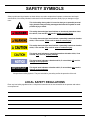
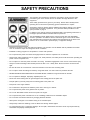
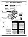
HP18289M
HYDRAULIC DIESEL
POWER UNIT
WARNING
To avoid serious injury or death
Read the Manual
Wear Eye
Protection
SAFETY, OPERATION AND MAINTENANCE
SERVICE MANUAL
Wear Ear
Protection
Wear Dust Mask
47351
Copyright © 2003, The Stanley Works
OPS/SVCE USA
62216 1/2004 Ver 2
Stanley Hydraulic Tools
3810 SE Naef Road
Milwaukie OR 97267-5698
503-659-5660
FAX 503-652-1780
www.stanley-hydraulic-tools.com
TABLE OF CONTENTS
Safety Symbols ........................................................................................ 4
Safety Precautions ................................................................................... 5
Tool Stickers & Tags ................................................................................. 6
Hydraulic Hose Requirements .................................................................. 7
HTMA Requirements ................................................................................ 8
Operation ................................................................................................. 9
Routine Maintenance .............................................................................. 13
Testing & Troubleshooting ....................................................................... 14
Specifications ......................................................................................... 16
Accessories ........................................................................................... 16
Service ................................................................................................... 17
Testing ................................................................................................... 20
Parts Lists .............................................................................................. 21
Parts Drawings ....................................................................................... 21
Engine & Blower Parts (Fig. 1A) ...................................................... 21
Frame Parts (Fig. 2A) ...................................................................... 22
Hose Basket (Fig. 3A) ..................................................................... 23
Hydraulic Tank Parts (Fig. 4A) ......................................................... 24
Dash Panel & Valve Assembly(Fig. 5A) ............................................ 25
Hose, Fittings & Clamps (Fig. 6A) ................................................... 26
Wiring Diagram (Fig. 7A) .................................................................. 27
Warranty ................................................................................................ 28
SERVICING THE STANLEY POWER UNIT: This manual contains safety, operation, and routine maintenance instructions. Stanley Hydraulic Tools recommends that servicing of hydraulic tools, other than
routine maintenance, must be performed by an authorized and certified dealer. Please read the following warning.
SERIOUS INJURY OR DEATH COULD RESULT FROM THE IMPROPER REPAIR OR SERVICE OF THIS TOOL.
REPAIRS AND / OR SERVICE TO THIS TOOL MUST ONLY BE
DONE BY AN AUTHORIZED AND CERTIFIED DEALER.
For the nearest authorized and certified dealer, call Stanley Hydraulic Tools at the number listed on the
back of this manual and ask for a Customer Service Representative.
3
SAFETY SYMBOLS
Safety symbols and signal words, as shown below, are used to emphasize all operator, maintenance and repair
actions which, if not strictly followed, could result in a life-threatening situation, bodily injury or damage to equipment.
This is the safety alert symbol. It is used to alert you to potential personal
injury hazards. Obey all safety messages that follow this symbol to avoid
possible injury or death.
This safety alert and signal word indicate an imminently hazardous situation which, if not avoided, will result in death or serious injury.
This safety alert and signal word indicate a potentially hazardous situation
which, if not avoided, could result in death or serious injury.
This safety alert and signal word indicate a potentially hazardous situation
which, if not avoided, may result in minor or moderate injury.
This signal word indicates a potentially hazardous situation which, if not
avoided, may result in property damage.
This signal word indicates a situation which, if not avoided, will result in
damage to the equipment.
IMPORTANT
This signal word indicates a situation which, if not avoided, may result in
damage to the equipment.
Always observe safety symbols. They are included for your safety and for the protection of the tool.
LOCAL SAFETY REGULATIONS
Enter any local safety regulations here. Keep these instructions in an area accessible to the operator and maintenance personnel.
4
SAFETY PRECAUTIONS
Tool operators and maintenance personnel must always comply with the safety
precautions given in this manual and on the stickers and tags attached to the
equipment.
To avoid serious injury or death
These safety precautions are given for your safety. Review them carefully before
operating the tool and before performing general maintenance or repairs.
Supervising personnel should develop additional precautions relating to the specific
work area and local safety regulations. If so, place the added precautions in the
space provided on page 4.
Read the Manual
Wear Eye
Protection
In addition to this manual, read and understand safety and operating instructions in
the Engine Operation Manual furnished with the power unit.
The HP18289M Hydraulic Diesel Power Unit will provide safe and dependable
service if operated in accordance with the instructions given in this manual. Read
and understand this manual and any stickers and tags attached to the Power Unit.
Failure to do so could result in personal injury or equipment damage.
Wear Ear
Protection
Wear Dust Mask
47351
• Operator must start in a work area without bystanders. The operator must be familiar with all prohibited work areas
such as excessive slopes and dangerous terrain conditions.
• Establish a training program for all operators to ensure safe operation.
• Do not operate the power unit unless thoroughly trained or under the supervision of an instructor.
• Always wear safety equipment such as goggles, ear, head protection, and safety shoes at all times when operating the
power unit and a hydraulic tool.
• Do not inspect or clean the power unit while it is running. Accidental engagement of the unit can cause serious injury.
• Always us hoses and fittings rated at 2500 psi/172 bar with a 4 to 1 safety factor. Be sure all hose connections are
tight.
• Be sure all hoses are connected for correct flow direction to and from the tool being used.
• Do not inspect hoses and fittings for leaks by using bare hands. “Pin-hole” leaks can penetrate the skin.
• NEVER OPERATE THE POWER UNIT IN A CLOSED SPACE. Inhalation of engine exhaust can be fatal.
• Do not operate a damaged, improperly adjusted power unit.
• Never wear loose clothing that can get entangled in the working parts of the power unit.
• Keep all parts of your body away from the working parts of the power unit.
• Keep clear of hot engine exhaust.
• Do not add fuel to the power unit while the power unit is running or is still hot.
• Do not operate the power unit if gasoline odor is present.
• Do not use flammable solvents around the power unit engine.
• Do not operate the power unit within 3.3 ft/1 m of buildings, obstructions or flammable objects.
• Do not reverse tool rotation direction by changing fluid flow direction.
• Allow power unit engine to cool before storing in an enclosed space.
• Always keep critical tool markings, such as lables and warning stickers legible.
• To avoid personal injury or equipment damage, all tool repair, maintenance and service must only be performed by
authorized and properly trained personnel.
5
TOOL STICKERS & TAGS
CAUTION
CERTAIN PARTS OF
THE POWER UNIT
WILL BE HOT.
AVOID CONTACT WITH
THOSE PARTS TO
PREVENT INJURY.
28047
HOT PARTS DECAL
(located on dash panel)
DANGER
OPERATE UNIT ONLY IN A
WELL VENTILATED AREA.
ENGINES PRODUCE CARBON
MONOXIDE WHICH IS AN
ODORLESS DEADLY POISON.
15875
SAFETY TAG (shown below)
(Do not remove until read)
28046
CARBON MONOXIDE DECAL
(located on dash panel)
DIESEL FUEL ONLY
32331
DIESEL FUEL ONLY DECAL
(located on fuel tank)
SERIAL NO. LOCATION
(At top of dash panel)
HYDRAULIC
FLUID
35686
HYDRAULIC FLUID DECAL
(located on hydraulic tank filter block)
OFF
ON
HYDRAULIC
VALVE
CHECK HYDRAULIC FLUID LEEL
WITH ENGINE AT IDLE. ADD FLUID
WHEN ENGINE IS OFF.
28988
EXHAUST FUMES STICKER
BATTERY CHARGE TAG
(Do not remove until read)
D A N G E R
1. FAILURE TO USE HYDRAULIC HOSE LABELED AND CERTIFIED AS NON-CONDUCTIVE WHEN USING HYDRAULIC TOOLS ON OR NEAR ELECTRICAL LINES MAY RESULT IN DEATH OR SERIOUS INJURY.
D DO NOT LIFT OR CARRY TOOL BY THE HOSES. DO
NOT ABUSE HOSE. DO NOT USE KINKED, TORN OR
DAMAGED HOSE.
BEFORE USING HOSE LABELED AND CERTIFIED AS
NON-CONDUCTIVE ON OR NEAR ELECTRIC LINES BE
SURE THE HOSE IS MAINTAINED AS NON-CONDUCTIVE.
THE HOSE SHOULD BE REGULARLY TESTED FOR ELECTRIC CURRENT LEAKAGE IN ACCORDANCE WITH
YOUR SAFETY DEPARTMENT INSTRUCTIONS.
3. MAKE SURE HYDRAULIC HOSES ARE PROPERLY CONNECTED TO THE TOOL BEFORE PRESSURING SYSTEM.
SYSTEM PRESSURE HOSE MUST ALWAYS BE CONNECTED TO TOOL "IN" PORT. SYSTEM RETURN HOSE
MUST ALWAYS BE CONNECTED TO TOOL "OUT" PORT.
REVERSING CONNECTIONS MAY CAUSE REVERSE
TOOL OPERATION WHICH CAN RESULT IN SEVERE PERSONAL INJURY.
2. A HYDRAULIC LEAK OR BURST MAY CAUSE OIL INJECTION INTO THE BODY OR CAUSE OTHER SEVERE PERSONAL INJURY.
A DO NOT EXCEED SPECIFIED FLOW AND PRESSURE
FOR THIS TOOL. EXCESS FLOW OR PRESSURE MAY CAUSE
A LEAK OR BURST.
B DO NOT EXCEED RATED WORKING PRESSURE OF HYDRAULIC HOSE USED WITH THIS TOOL. EXCESS PRESSURE MAYCAUSE A LEAK OR BURST.
51297
CHECK HYDRAULIC FLUID DECAL
(located on dash panel)
The safety tag at right is
attached to the power unit
when shipped from the
factory. Read and understand the safety instructions listed on this tag
before removal. We
suggest you retain this tag
and attach it to the tool
when not in use.
D A N G E R
D A N G E R
C CHECK TOOL HOSE COUPLERS AND CONNECTORS
DAILY FOR LEAKS. DO NOT FEEL FOR LEAKS WITH YOUR
HANDS. CONTACT WITH A LEAK MAY RESULT IN SEVERE
PERSONAL INJURY.
4. DO NOT CONNECT OPEN-CENTER TOOLS TO CLOSEDCENTER HYDRAULIC SYSTEMS. THIS MAY RESULT IN
LOSS OF OTHER HYDRAULIC FUNCTIONS POWERED
BY THE SAME SYSTEM AND/OR SEVERE PERSONAL INJURY.
5. BYSTANDERS MAY BE INJURED IN YOUR WORK AREA.
KEEP BYSTANDERS CLEAR OF YOUR WORK AREA.
6. WEAR HEARING, EYE, FOOT, HAND AND HEAD PROTECTION.
7. TO AVOID PERSONAL INJURY OR EQUIPMENT DAMAGE,
ALL TOOL REPAIR MAINTENANCE AND SERVICE MUST
ONLY BE PERFORMED BY AUTHORIZED AND PROPERLY
TRAINED PERSONNEL.
I M P O R TA N T
I M P O R TA N T
READ OPERATION MANUAL AND
SAFETY INSTRUCTIONS FOR THIS
TOOL BEFORE USING IT.
READ OPERATION MANUAL AND
SAFETY INSTRUCTIONS FOR THIS
TOOL BEFORE USING IT.
USE ONLY PARTS AND REPAIR
PROCEDURES APPROVED BY
STANLEY AND DESCRIBED IN THE
OPERATION MANUAL.
USE ONLY PARTS AND REPAIR
PROCEDURES APPROVED BY
STANLEY AND DESCRIBED IN THE
OPERATION MANUAL.
TAG TO BE REMOVED ONLY BY
TOOL OPERATOR.
15875
SEE OTHER SIDE
TAG TO BE REMOVED ONLY BY
TOOL OPERATOR.
15875
SAFETY TAG (shown smaller then actual size)
6
HYDRAULIC HOSE REQUIREMENTS
HOSE TYPES
Hydraulic hose types authorized for use with Stanley Hydraulic Tools are as follows:
! Certified non-conductive
" Wire-braided (conductive)
$ Fabric-braided (not certified or labeled non-conductive)
Hose ! listed above is the only hose authorized for use near electrical conductors.
Hoses " and $ listed above are conductive and must never be used near electrical conductors.
HOSE SAFETY TAGS
To help ensure your safety, the following DANGER tags are attached to all hose purchased from Stanley Hydraulic
Tools. DO NOT REMOVE THESE TAGS.
If the information on a tag is illegible because of wear or damage, replace the tag immediately. A new tag may be
obtained from your Stanley Distributor.
D A N G E R
D A N G E R
1 FAILURE TO USE HYDRAULIC HOSE LABELED AND CERTIFIED AS NON-CONDUCTIVE WHEN
USING HYDRAULIC TOOLS ON OR NEAR ELECTRIC LINES MAYRESULT IN DEATH OR SERIOUS
INJURY.
FOR PROPER AND SAFE OPERATION MAKE SURE THAT YOU HAVE BEEN PROPERLY TRAINED IN
CORRECT PROCEDURES REQUIRED FOR WORK ON OR AROUND ELECTRIC LINES.
3. DO NOT EXCEED HOSE WORKING PRESSURE OR ABUSE HOSE. IMPROPER USE OR HANDLING
OF HOSE COULD RESULT IN BURST OR OTHER HOSE FAILURE. KEEP HOSE AS FAR AWAY AS
POSSIBLE FROM BODY AND DO NOT PERMIT DIRECT CONTACT DURING USE. CONTACT AT THE
BURST CAN CAUSE BODILY INJECTION AND SEVERE PERSONAL INJURY.
4. HANDLE AND ROUTE HOSE CAREFULLY TO AVOID KINKING, ABRASION, CUTTING, OR CONTACT
WITH HIGH TEMPERATURE SURFACES. DO NOT USE IF KINKED. DO NOT USE HOSE TO PULL OR
LIFT TOOLS, POWER UNITS, ETC.
2. BEFORE USING HYDRAULIC HOSE LABELED AND CERTIFIED AS NON-CONDUCTIVE ON OR
NEAR ELECTRIC LINES. WIPE THE ENTIRE LENGTH OF THE HOSE AND FITTING WITH A CLEAN
DRY ABSORBENT CLOTH TO REMOVE DIRT AND MOSISTURE AND TEST HOSE FOR MAXIMUM
ALLOWABLE CURRENT LEAKAGE IN ACCORDANCE WITH SAFETY DEPARTMENT
INSTRUCTIONS.
5. CHECK ENTIRE HOSE FOR CUTS CRACKS LEAKS ABRASIONS, BULGES, OR DAMAGE TO
COUPLINGS IF ANY OF THESE CONDITIONS EXIST, REPLACE THE HOSE IMMEDIATELY. NEVER
USE TAPE OR ANY DEVICE TO ATTEMPT TO MEND THE HOSE.
6. AFTER EACH USE STORE IN A CLEAN DRY AREA.
SEE OTHER SIDE
SEE OTHER SIDE
SIDE 1
3
D O N O T R E M O V E T H I S TA G
D O N O T R E M O V E T H I S TA G
THE TAG SHOWN BELOW IS ATTACHED TO "CERTIFIED NON-CONDUCTIVE" HOSE
SIDE 2
(shown smaller than actual size)
D A N G E R
D A N G E R
1 DO NOT USE THIS HYDRAULIC HOSE ON OR NEAR ELECTRIC LINES. THIS HOSE IS NOT
LABELED OR CERTIFIED AS NON-CONDUCTIVE. USING THIS HOSE ON OR NEAR ELECTRICAL
LINES MAY RESULT IN DEATH OR SERIOUS INJURY.
5. CHECK ENTIRE HOSE FOR CUTS CRACKS LEAKS ABRASIONS, BULGES, OR DAMAGE TO
COUPLINGS IF ANY OF THESE CONDITIONS EXIST, REPLACE THE HOSE IMMEDIATELY. NEVER
USE TAPE OR ANY DEVICE TO ATTEMPT TO MEND THE HOSE.
2. FOR PROPER AND SAFE OPERATION MAKE SURE THAT YOU HAVE BEEN PROPERLY TRAINED IN
CORRECT PROCEDURES REQUIRED FOR WORK ON OR AROUND ELECTRIC LINES.
6. AFTER EACH USE STORE IN A CLEAN DRY AREA.
3. DO NOT EXCEED HOSE WORKING PRESSURE OR ABUSE HOSE. IMPROPER USE OR HANDLING
OF HOSE COULD RESULT IN BURST OR OTHER HOSE FAILURE. KEEP HOSE AS FAR AWAY AS
POSSIBLE FROM BODY AND DO NOT PERMIT DIRECT CONTACT DURING USE. CONTACT AT
THE BURST CAN CAUSE BODILY INJECTION AND SEVERE PERSONAL INJURY.
4. HANDLE AND ROUTE HOSE CAREFULLY TO AVOID KINKING, CUTTING, OR CONTACT WITH
HIGH TEMPERATURE SURFACES. DO NOT USE IF KINKED. DO NOT USE HOSE TO PULL OR LIFT
TOOLS, POWER UNITS, ETC.
D O N O T R E M O V E T H I S TA G
D O N O T R E M O V E T H I S TA G
THE TAG SHOWN BELOW IS ATTACHED TO "CONDUCTIVE" HOSE.
SEE OTHER SIDE
SEE OTHER SIDE
SIDE 1
SIDE 2
(shown smaller than actual size)
HOSE PRESSURE RATING
The rated working pressure of the hydraulic hose must be equal to or higher than the relief valve setting on the
hydraulic system.
7
HTMA REQUIREMENTS
TOOL CATEGORY
HYDRAULIC SYSTEM
REQUIREMENTS
TYPE 1
TYPEII
TYPEIII
TYPE RR
TOOL OPERATING PRESSURE
(at the power supply outlet)
4-6 gpm
(15-23 lpm)
2000 psi
(138 bar)
7-9 gpm
(26-34 lpm)
2000 psi
(138 bar)
11-13 gpm
(42-49 lpm)
2000 psi
(138 bar)
9-10.5 gpm
(34-40 lpm)
2000 psi
(138 bar)
SYSTEM RELIEF VALVE SETTING
(at the power supply outlet)
2100-2250 psi
(145-155 bar)
2100-2250 psi
(145-155 bar)
2100-2250 psi
(145-155 bar)
2200-2300 psi
(152-159 bar)
MAXIMUM BACK PRESSURE
(at tool end of the return hose)
250 psi
(17 bar)
250 psi
(17 bar)
250 psi
(17 bar)
250 psi
(17 bar)
Measured at a max. fluid viscosity of:
(at min. operating temperature)
400 ssu*
400 ssu*
400 ssu*
400 ssu*
(82 centistokes) (82 centistokes) (82 centistokes) (82 centistokes)
TEMPERATURE
Sufficient heat rejection capacity
to limit max. fluid temperature to:
(at max. expected ambient temperature)
140° F
(60° C)
140° F
(60° C)
140° F
(60° C)
140° F
(60° C)
Min. cooling capacity
at a temperature difference of
between ambient and fluid temps
3 hp
(2.24 kW)
40° F
(22° C)
5 hp
(3.73 kW)
40° F
(22° C)
7 hp
(4.47 kW)
40° F
(22° C)
6 hp
(5.22 kW)
40° F
(22° C)
FILTER
25 microns
Min. full-flow filtration
30 gpm
Sized for flow of at least:
(114 lpm)
(For cold temp. startup and max. dirt-holding capacity)
25 microns
30 gpm
(114 lpm)
25 microns
30 gpm
(114 lpm)
25 microns
30 gpm
(114 lpm)
HYDRAULIC FLUID
Petroleum based
(premium grade, anti-wear, non-conductive)
VISCOSITY
(at min. and max. operating temps)
100-400 ssu*
100-400 ssu*
(20-82 centistokes)
FLOW RATE
NOTE:
Do not operate the tool at oil temperatures above 140° F (60° C). Operation at higher temperatures can cause operator
discomfort at the tool.
100-400 ssu*
100-400 ssu*
NOTE:
When choosing hydraulic fluid, the expected oil temperature extremes that will be experienced in service determine the
most suitable temperature viscosity characteristics. Hydraulic fluids with a viscosity index over 140 will meet the requirements over a wide range of operating temperatures.
*SSU = Saybolt Seconds Universal
NOTE:
These are general hydraulic system requirements. See tool Specification page for tool specific requirements.
8
OPERATION
PREPARATION FOR USE
VISCOSITY (FLUID THICKNESS)
U.S.
Do not operate the power unit until you have read the
engine operating and maintenance instructions manual
furnished with the unit.
METRIC
50°F 450 SSU Maximum
100°F 130-200 SSU
140°F 85 SSU Minimum
1. ENGINE CRANKCASE OIL LEVEL
10°C 95 C.S.
38°C 27-42 C.S.
60°C 16.5 C.S. Min
Pour Point -10°F/-23°C Minimum (for cold startup)
Always check the oil level before starting the engine. Make
sure the oil level is at the FULL MARK on the dipstick. Do
not overfill. Use diesel engine lube-oil to MIL-L-2104D with
S.3 (MIL-L-45199B) detergent grade.
Viscosity Index (ASTM D-2220) 140 Minimum
Demulsibility (ASTM D-1401) 30 Minutes Maximum
IMPOR
TANT
IMPORT
Flash Point (ASTM D-92) 340°F/171°C Minimum
The engine oil sump must never be
overfilled. Overfilling can cause the
engine to overheat and cause
crankshaft seal damage.
Oxidation (ASTM D-943) 1000 Hours Minimum
Rust Inhibition (ASTM D-665 A & B) Pass
Pump Wear Test (ASTM D-2882) 60 mg Maximum
The following fluids work well over a wide temperature
range at startup. Allow moisture to settle out and resist
biological growth that may occur in cool operating
hydraulic circuits. These fluids are recommended by
Stanley Hydraulic Tools. Other fluids that meet or
exceed the specifications of these fluids may also be
used.
2. ENGINE FUEL LEVEL
Check the fuel level. If low, fill with DF-1 or DF-2 diesel
fuel (A.S.T.M. D975-66T No. 1 or 2 dark).
WARNING
Chevron AW-MV-32
Exxon "Univis" J-26
Mobil D.T.E. 13
Gulf "Harmony" AW-HVI-150-32
Shell "Tellus" T-32
Texaco "Rando" HD-AZ
Union "Unax" AW-WR-32
Terresolve EnviroLogic 132
Shut the engine off before attempting to
add fuel to the fuel tank. Do not remove
the fuel cap while the engine is running.
Do not add fuel to the tank while the
engine is hot. Do not fill the fuel tank to a
point of overflowing.
3. HYDRAULIC FLUID
4. HYDRAULIC CONNECTIONS
Check the dip stick in the hydraulic fluid reservoir for the
proper fiuid level. Proper fluid level is indicated when the
center section of the dipstick shows oil. If the center
section of the dipstick does not show add hydraulic fluid.
Facing the panel control valve, the far right-hand male
quick disconnect fitting is the pressure (FLUID OUT)
fitting. The left-hand female quick disconnect fitting is
the return (FLUID IN) fitting.
NOTE:
Do not over fill the hydraulic tank. Oil will rise and leak
from the tank breather.
The recommended hose length is 25 ft/8 m with a 1/2
inch/12.7 mm inside diameter. The hoses must have a
working pressure rating of at least 2500 psi/175 bar.
Each hose end must have male thread ends compatible with H.T.M.A. (HYDRAULIC TOOL MANUFAC-
Use fluids meeting the following specifications.
9
OPERATION
TURERS ASSOCIATION) quick disconnect fittings
(NPT type threads). (See Figure 1.)
CONTROL PANEL
Longer hoses may be used when necessary, but can
effect the operation of the engine automatic throttle
due to fluid resistance in the hose. If small diameter or
long hoses are used, or if restrictive fittings are connected to the supply and return ports, the pressure
required to push the fluid through the system and back
to the hydraulic tank will be higher. If the pressure is
too high, this will cause the engine RPM to remain at
full load if "AUTO" is selected on the automatic throttle.
Also see "HYDRAULIC HOSE REQUIREMENTS"
earlier in this manual.
PRESSURE
RETURN
H.T.M.A. 1/2 INCH
FEMALE QUICK
DISCONNECT COUPLER
H.T.M.A. 1/2 INCH MALE
QUICK DISCONNECT
COUPLER
QUICK DISCONNECT COUPLERS
1/2 INCH MALE PIPE
HOSE END
H.T.M.A. approved quick disconnect couplings are
installed to hydraulic hoses so that the direction of oil
flow is always from the male to the female quick
disconnect as shown in figure 1. Quick disconnect
couplings and hose fittings are selected so that additional fittings such as reducer or adapter fittings are not
required.
1/2 INCH I.D. HOSE, 25 FT
LONG WITH 2500 PSI/
172 BAR RATING AND
4 TO 1 SAFETY FACTOR
P/N 31848
50 ft HOSE & COUPLER
ASSEMBLY
If adapter fittings are used, they must be approved
steel hydraulic fittings meeting a minimum operating
pressure rating of 2500 psi/172 bar. Do not use
galvanized pipe fittings or black pipe fittings.
PRESSURE
RETURN
Use thread tape or pipe joint compound when installing
quick disconnect couplings to hose or tool fittings.
Follow the instructions furnished with the selected
thread sealant. DO NOT OVERTIGHTEN THE
FITTINGS.
1/2 INCH MALE PIPE
HOSE END
H.T.M.A. 1/2 INCH
FEMALE QUICK
DISCONNECT COUPLER
5. BATTERY
The supplied 12 Volt DC no maintenance dry cell
battery is fully charged.
H.T.M.A. 1/2 INCH MALE
QUICK DISCONNECT
COUPLER
The battery is air transportable and is suitable for cold
weather applications. Make sure the battery cables are
tight and charging circuit functions are operating
properly.
ADAPTER, 3/8 INCH MALE
PIPE x -8 SAE O-RING
RETURN
NOTICE
PRESSURE
Do not charge the battery with a standard
automotive battery charger. This type of
charger produces a charging amperage
higher than 2 amps. Charging the battery at
higher than 2 amps will damage the battery.
TOOL
Figure 1. Hydraulic Connections
10
OPERATION
4. Push the hydraulic tool circuit control lever to the "ON"
position (right) (see Figure 4).
STARTUP
SEE "CONTROL PANEL" - FIGURE 2
1. Before starting the engine, assure the hydraulic circuit
control lever is in the "TOOL OFF" position (left) and the
throttle cable is fully depressed.
OIL PRESSURE LIGHT
A problem with the engine oil lubricating system exists if
the oil pressure light remains on after the engine has
started. Shutdown the engine and then have the lubricating
system serviced by a qualified technician.
COLD WEATHER STARTUP
1. Before starting the engine, assure the hydraulic circuit
control lever is in the "TOOL OFF" position (left) and the
throttle cable is fully depressed.
2. Press and hold the glow plug switch for 10-15 seconds.
Release the glow plug button and turn the start switch to the
third start position to crank the engine.
NOTE:
Hydraulic fluids are thicker in cold weather. It is
recommended that the engine be ran at low idle long
enough to bring the fluid temperature up to a minimum of 50°F/ 10°C or until the top of the hydraulic
filter feels warm.
Figre 2. Control Panel
2. Turn the three-position starter switch clockwise until the
engine begins to crank. When the engine starts, release the
switch. The switch will default to the "ON" (2nd) position as
shown in Figure 3.
Glow Plug
Button
Battery
Oil
Pressure Charge
Light
Light
3. When the engine is warmed up, pull the throttle cable to
the full open position and lock it into place. This will
provide the proper rpm to obtain 8 gpm required to power
the hydraulic tools.
4. Push the hydraulic tool circuit control lever to the "ON"
position (right) (see Figure 4).
OFF
"ON"
2nd Position
"START"
3rd Position
Starter
Switch
Figure 3. Engine Control Panel
3. When the engine is warmed up, pull the throttle cable to
the full open position and lock it into place. This will
provide the proper rpm to obtain 8 gpm / 30 lpm required
to power the hydraulic tools.
Figure 4. Control Panel to "ON" Position
11
OPERATION
power unit weighs 384 lbs. Using the extracted handle
bars to lift the power unit will cause damage.
TOOL OPERATION
STORAGE
1. With the control lever at the "ON" position.
2. Activate the tool. The automatic throttle will increase
engine speed to permit proper tool operation. When the
tool is deactivated, the automatic throttle allows the
engine to return to idle.
• Clean the unit thoroughly before storage. Do not use
water pressure.
NOTE:
If the tools and tool hoses are cold, it is recommended
to allow hydraulic fluid to circulate through the tool
hoses until warm before using the tools.
• If the unit will be stored for a prolonged period (over 30
days, up to 6 months), replace the fuel filter then add
diesel fuel additive to the fuel tank to prevent the fuel from
gumming. Be sure to follow the instructions provided with
the fuel additive. Run engine for a short period to circulate
the additive.
• Always store the unit in a clean and dry facility.
SHUTDOWN
• Check hydraulic reservoir for water. If water is found,
change the oil and circulate it through the tool hose and
tool. (See "HYDRAULIC SYSTEM MAINTENANCE"
earlier in this section).
1. Place the circuit control lever in the "OFF" position.
2. Push the throttle control completely in. Allow the
engine to idle for approximately one minute and then
switch the starter switch to the "OFF" position.
• Disconnect tool hoses.
3. Pull the engine "STOP" knob.
NOTE:
The starter switch must be turned to the "OFF" position.
Failure to do so will cause battery failure.
USING THE HANDLE BARS
The power unit is equipped with retractable handle bars so
it can easily be moved at the job site.
NO
TICE
NOTICE
DO NOT lift the power unit with the handle bars
extracted.
1. To use the handle bars, pull each handle bar straight out.
Twist the bars until locking mechanism engages. The power
unit may now be pushed about in a wheel-barrow manner.
2. To retract the handle bars, disengage the locking mechanism, then push the bars inward
NOTE:
Use the correct number of personel to lift or hoist the
HP18289M Power Unit to and from the trailer. The
12
ROUTINE MAINTENANCE
ENGINE MAINTENANCE
Follow the maintenance schedule and general maintenance instructions in the engine maintenance and operation manual furnished with the power unit. Normal maintenance includes:
• Inspect the air filter daily. Clean foam air cleaner every 3
months or 50 hours at a minimum.
• Keep air out of the hydraulic lines. Hydraulic system
overheating and foam at the hydraulic tank breather
indicates air is present in the lines. Keep all suction line
fittings and clamps tight.
• Hydraulic system wear is noted by increased heat during
tool operation, reduced tool performance and eventual
system breakdown.
• Replace dry air filter every 200 hours of operation.
• Operate with the fluid temperature at 50° - 140°F / 10° 60°C for improved seal and hose life, and maximum
efficiency.
• Replace fuel filter every 100 hours of operation.
FILLING THE RESERVOIR
• Replace spark plugs every 300 hours or every year.
1. Make sure the engine is stopped before opening the
filler cap. Fill slowly with the recommended fluid as listed
in the "Operation" section of this manual.
• Change engine oil after first 50 hours of operation, then
after every 200 hours of operation. If engine has been
operating under heavy load or in high ambient temperature, moist or dusty conditions then change the oil every 25
hours of operation.
• Change oil filter when engine oil is changed.
• Check oil level daily.
• Remove dirt and debris from engine with a cloth or brush
daily. Do not use water spray.
• Clean air cooling system every 100 hours of operation.
2. Add fluid as needed.
3. Secure the filler cap before restarting the engine.
REMOVING CONDENSED MOISTURE FROM
HYDRAULIC FLUID
Condensation is a frequent problem with cool hydraulic
circuits. This condition occurs in moist or cold climates.
When warm air in the hydraulic tank draws moisture from
the cooler air outside, water accumulates in the tank.
HYDRAULIC SYSTEM
MAINTENANCE
1. To remove water from the hydraulic system, use the
"PRESSURE" hose without the quick-disconnect coupler
attached. Start the engine and let it run at the idle speed.
Pump the fluid into a clean 5 gal./20 ltr container.
• Check hydraulic fluid level daily. Add fluid per specifications in this manual. (See "HYDRAULIC FLUID" under the
section titled "OPERATING INSTRUCTIONS".
2. Turn the engine "OFF" as soon as the hydraulic tank
(reservoir) is empty. DO NOT operate the engine with an
empty hydraulic tank as pump damage may occur.
• Each day, check hydraulic lines and fittings for leaks,
kinks, etc. Do not use your hand to perform this check.
3. Allow the fluid to sit long enough for the water to settle to
the bottom of the container. Slowly pour the fluid back into
the hydraulic tank, avoiding the water at the bottom of the
container.
• Change the hydraulic filter element every 200 hours of
operation. Change more often if cold, moist or dusty conditions exist.
• Check oil cooler for debris. Remove debris with air
pressure.
• Make sure the suction hose (from the hydraulic tank to the
inlet manifold) is clamped securely. This reduces the risk of
pump cavitation. All pump fittings should be tight.
13
TESTING & TROUBLESHOOTING
GENERAL
Tests and adjustments should be performed periodically to
ensure the power unit is operating at maximum efficiency.
Stanley Circuit Tester (Part Number 04182) is recommended. This tester can be used to isolate problems in
both the engine and hydraulic system prior to any power
unit disassembly.
a. Access to the relief valve can be gained through the top of
the power unit between the dash panel and top grille. If more
room is required, remove the dash panel. Use a open end or
box end wrench to remove the cap on the relief valve.
b. Use an Allen wrench to adjust the relief valve. Turn
clockwise to raise the pressure and counterclockwise to
reduce the pressure.
TESTING THE HYDRAULIC CIRCUIT
The following tests can be performed to ensure that the
hydraulic pump is supplying the correct flow and pressure
and that the system relief valve is operating properly.
c. Replace the cap and test for 2100-2200 psi/148-155 bar
as described above.
d. Repeat the above test with the hoses and tester
connected to the other circuit.
During these tests, make sure the engine is warm
and operating smoothly. If test results are not as specified,
refer to the troubleshooting table given in this section for
possible causes.
TESTING THE 8 GPM CIRCUIT
To test the circuit, proceed as follows:
1. Set the Circuit Control Lever to the "OFF" position.
2. Connect the Stanley Circuit Tester across two hose ends
(where the tool would normally be connected).
3. Fully open the tester restrictor valve (counter clockwise).
4. Start the engine and allow it to run until warm.
5. Pull the engine throttle control completely "OUT" so that
the engine is running at full RPM.
6. Move the Circuit Control Lever to the "ON" position.
7. With the engine at high speed, the test flow gauge should
read at least 8 gpm / 30 lpm.
8. Slowly turn the restrictor valve clockwise while watching
the pressure gauge. The flow rate should stay at
8-9 gpm / 30-34 Ipm as the pressure gauge reaches 21002200 psi / 148-155 bar.
9. At 2100-2200 psi/148-155 bar the relief valve should
begin to open. The pressure at which the relief valve just
begins to open is commonly referred to as the "cracking
pressure". At the "cracking pressure", the flow rate should
start to drop because the relief valve is allowing fluid to
bypass to the hydraulic reservoir. The "cracking pressure" is
preset at the factory and if it is not within the above range,
the relief valve must be reset as follows:
14
TROUBLESHOOTING
PROBLEM
Engine will not run.
Fluid blowing out of fluid
reservoir vent.
Hydraulic tool won't operate.
CAUSE
REMEDY
Battery not connected.
Attach battery cables, check wires.
Weak battery.
Test battery, charge or replace.
No fuel.
Add Fuel.
Fuel filter plugged.
Replace fuel filter.
Defective pump seal.
Replace pump seal.
Hydraulic tank overfilled.
Correct the fluid level.
Control lever setting incorrect. Set control lever to "TOOL ON".
Incorrect hose connection to
tool.
Make sure the tool hose goes
from pressure fitting to tool
and back to the return fitting.
Fluid always flows from the male to
female fittings.
Quick disconnect fittings
defective.
Detach from hose, connect set
together and check for free flow.
Hydraulic fluid level low.
Check for correct fluid level. Fill
using the recommended fluid.
Pump coupling defective.
Check coupling between pump and
blower. The coupler should slide only
..03-.06 in./.80-1.60 mm inches
between blower and pump.
Relief valve stuck open.
Adjust or replace valve.
Incorrect throttle setting
Pull throttle completely out so that
engine runs at full rpm.
15
SPECIFICATIONS
Engine: .................................................................................................... Duetz Ruggerini MD191, 2 cylinder, diesel, 19 hp
Engine Lube System: .................................................................................................................................... Pressure Lube
Capacity .................................................................................................................. 8 gpm @ 2000 psi / 30 lpm @ 138 bar
Length: ......................................................................................................................................................... 35.5 in. / 90 cm
Width: .............................................................................................................................................................. 24 in: / 61 cm
Height: (with hose basket) ....................................................................................................................... 39.5 in. / 100.3 cm
Weight (Wet): .................................................................................................................................. 384 lbs / 174 kg
Fuel Tank Capacity: ...................................................................................................................................... 4.2 gal. / 15 ltr
Estimated Gas Consumption Per Hour ............................................................................................................ 1.3 gal / 4 ltr
Hydraulic Reservor Capacity: ......................................................................................................................... 2.7 gal. / 11 ltr
Relief Valve "crack" setting ...................................................................................................................... 2150 psi / 148 bar
Full relief setting ....................................................................................................................................... 2500 psi / 172 bar
or
D
EHTMA Category ................................................. "C" (20 lpm @ 138 bar) or "D" (30 lpm @ 138 bar)
Sound Pressure Level @ 1 meter ............................................................................................................................. 100 dBA
Sound Power Level ......................................................................................................................................... 111 dBA (LWA)
Vibration Level ..................................................................................................................................................................N/A
ACCESSORIES
50 ft Dual Hydraulic Hose, 1/2 in. I.D.,Wire Braid with Couplers ................................................................................ 31848
25 ft Dual Hydraulic Hose, 1/2 in. I.D.,Wire Braid with Couplers ................................................................................ 31972
Flush-Face Coupler Set, 1/2 in. NPT, NSN 4730-01-479-0555 ................................................................................... 24070
Bruning Flush-Face Coupler Set, 1/2 in. NPT ............................................................................................................. 03974
Flow and Pressure Tester ............................................................................................................................................ 04182
Adaptor, 1/2 in. SAE to 3/8 in. Male Pipe .................................................................................................................... 00936
Bushing, 1/2 in. to 3/4 in. ............................................................................................................................................ 02151
Hex Nipple, 1/2 in. Male Pipe ...................................................................................................................................... 04192
Hex Nipple, 3/8 in. Male Pipe ...................................................................................................................................... 03044
MAAS TOOLS NSN'S
Military Pavement Breaker (Stanley # Br6713016) ................................................................................. 3820-012-421-440
Military Hammer Drill (Stanley # HD45110D) .......................................................................................... 5130-01-178-6338
MAAS Post Driver (Stanley # PD48142) ................................................................................................. 1710-01-468-8021
MAAS Post Puller (Stanley # PP10100A) ............................................................................................... 1710-01-468-8024
Hydraulic Power Unit (Gasoline Powered) (Stanley # HP18299M) ......................................................... 4320-01-450-3557
Hydraulic Power Unit (Diesel Powered) (Stanley # HP18289M) ............................................................. 1730-01-342-2183
50 ft Dual Hose Assembly, includes Couplers (Stanley # 31848) ........................................................... 4720-01-361-5033
17
SERVICE INSTRUCTIONS
GENERAL
Using the fittings or the wood dowels, plug one end of each
of the short hoses.
Service instructions in this section are limited to parts and
components other than the engine and hydraulic pump.
Other major components should be serviced by representatives of the respective manufacturers as follows:
c. Thoroughly clean the exterior of the connections of the
fuel supply line (12, fig 6A) and the fuel return line (10, fig 6A)
where they are connected to the fuel tank. Disconnect one
fuel line at a time, quickly plugging the fuel line and the
tank port with the wood dowels or fittings and the short
hose lengths to minimize spillage. Wipe up any spillage
using appropriate disposal methods.
ENGINE
Duetz Ruggerini, 19 hp
Model: MD191
Model HP18289M: The fuel tank must be removed in
order to remove the engine.
The engine should be serviced only by Ruggerini Certified
Dealers. It is recommended to contact Deutz Corporation
for the nearest authorized Ruggerini representative at
1-770-564-7100.
a. Disconnect the hoses (13 & 14, fig 6A) and plug them with
a plug fittings or wood dowels.
HYDRAULIC PUMP
b. Remove the 3 capscrews (23, fig 2A) that secure the
tank to the frame. Remove the fuel tank.
4. Remove the air cleaner cover and air cleaner.
5. Remove the top grille (8, fig 2 or 47, fig 2A).
ENGINE REMOVAL
6. Remove the fasteners that retain the cooler mounts (6 &
10, fig 1 & fig 1A) and the cooler brace (12, fig 1 and fig
1A) and remove the mounts and brace. The switch box (7,
fig 1) and wiring will be loose after this procedure and can
then be removed with the engine.
Most engine servicing can be performed without removing
the engine. Consult with your Ruggerini Dealer regarding
engine repairs.
1. Remove both battery connections. Remove the battery
strap or battery hold down. Remove the battery.
7. Tie the oil cooler (8, fig 1 and fig 1A) to the frame rails of
the frame (55, fig 2 or 39 fig 2A) so that it will not interfere
with removal of the engine.
2. Remove the wheels by first removing one retaining ring,
slide one washer and wheel off of the axle, then pull the
other wheel and axle out of the axle brackets.
8. Disconnect the two wires leading to the hour meter.
FUEL LINES AND FUEL TANK
9. Disconnect the throttle cable (6, fig 2 or fig 2A) at the
engine.
3. Follow the applicable instructions below to disconnect
engine fuel lines.
10. Using an Allen wrench, loosen the setscrews on the
coupling assy (27 & 28, fig 2 or 16, fig 2A).
Model HP18289M: The hoses at the fuel tank must be
disconnected. Obtain the following materials for plugging the
fuel tank ports and the fuel hoses.
11. Unscrew and remove the nuts (37, fig 2 or 35, fig 2A)
and capscrews (20, fig 1 & fig 1A) and washers.
12. Slide the engine forward being careful not to entangle
the electrical wiring and not to damage other components.
a. Two short lengths (2 to 3 inches) of fuel hose one with 1/
4 inch inside diameter and one with 1/8 inch inside diameter.
13. Remove the coupling sleeve (28, fig 2 or 17, fig 2A).
b. Four plug fittings or wood dowels to plug one end of
each of the short hoses and also the ends of the hoses
disconnected from the fuel tank.
14. Slide the engine out the fuel tank side of the frame.
17
SERVICE
TO REINSTALL ENGINE
OIL COOLER
1. Reverse the above procedures to reinstall the engine.
1. Remove the top grille (8, fig 2 or 47, fig 2A).
2. Install the capscrews (20, fig 1 & fig 1A) so that one
washer (21, fig 1A or 36 fig 1) is installed next to the head of
the capscrew, one washer is installed between the engine
mounting bracket and the frame and one washer is installed
between the nut (37, fig 2 or 35, fig 2A) and the frame.
Tighten the capscrews and nuts to 20 ft. lb torque.
2. Remove the hoses (3 & 9, fig 6 or 6A).
3. Remove the fasteners that retain the cooler mounts (6 &
10, fig 1 or 1A) and the cooler brace (12, fig 1 or 1A) and
remove the mounts and brace. The switch box (7, fig 1)
and wiring will be loose after this procedure.
3. After installing the engine, adjust the coupling sleeve as
follows:
4. Lift the cooler out.
a. Move the coupling flange forward or backwards on the
engine drive shaft until the drive shaft is recessed into the
coupling flange bore .435 inches. Tighten the setscrews.
RE-ASSEMBLY
1. Reverse the above procedure to reinstall the cooler.
b. Adjust the coupling flange on the pump until the coupling
sleeve has 1/32-1/16 inch end play.
HYDRAULIC PUMP
1. First remove the hydraulic fluid from the tank by either
pumping it out with a portable drill pump or draining it into
a container.
BLOWER HUB, BLOWER WHEEL,
INLET RING, & BLOWER HOUSING
1. Remove the engine as described earlier in this section.
2. Remove the grille (19, fig 2 or 5, fig 2A).
2. To remove the blower wheel, remove the five screws
(31, fig 1 or fig 1A) around the housing inlet ring (30, fig 1
or 1A) and remove the ring.
3. Disconnect the pressure hoses and inlet manifold at the
pump.
3. Remove the 2 capscrews (21, fig 2 or 10, fig 2A) and
then remove the pump.
3. Remove the blower wheel (26, fig 1 or 24, fig 1A) with the
blower hub (it may be required to remove the three hub
screws and use them as jack screws in the adjacent holes)
(25, fig 1 or 1A) by loosening the set screws on the coupler
flange (28, fig 1 or 1A).
RE-ASSEMBLY
1. Reverse the above procedure to reinstall the pump and
observe the following step.
4. Remove the four capscrews (14, fig 1 or 1A) holding the
blower housing (16, fig 1 or 1A) to the engine. Remove the
housing.
a. Insure the coupling sleeve is installed correctly (see
REINSTALL ENGINE).
RE-ASSEMBLY
FUEL TANK
1. Reverse the above procedure to reinstall the above
components and observe the following added procedures.
1. If the fuel tank contains fuel, take extreme precautions
to remove the fuel into approved containers. Do not
attempt to service the fuel tank in unventilated areas or in
areas containing electric or natural gas appliances which
may start-up unexpectantly or in shop areas where grinding
or welding is present, all of which can ignite the fuel vapors.
a. Install capscrews which hold the blower housing to the
engine using Loctite™ 242.
b. Install capscrews which hold the blower wheel to the
blower hub using Loctite™ 680 and torque to 80-100 lb. in.
18
SERVICE
2. Follow step 3 under "ENGINE REMOVAL" to disconnect
and plug the fuel lines.
removed by first removing the capscrews (15, fig 2 or 3, fig
2A and 27, fig 5A). Then remove the capscrews (19, fig 5A)
holding the valve to the dash panel.
To remove the tank, first remove the 3 capscrews (23, fig 2A)
and tank support (37, fig 2A) at the top of the fuel tank only.
Slide the tank out.
VALVE SPOOL
RE-ASSEMBLY
1. Reverse the above procedures to reinstall the fuel tank.
HYDRAULIC TANK
1. First remove the hydraulic fluid from the tank by either
pumping it out with a portable drill pump or draining it into
a container.
2. Remove the grille (19, fig. 2 or 5, fig 2A) by removing
the 4 capscrews (9, fig. 2 or 3, fig 2A).
3. Remove the hoses (6 & 9, fig 6 or 6A) by loosening the
hose clamps.
4. The hydraulic tank can now be removed by removing
the 2 capscrews (32, fig. 2 or 23, fig 2A) and the tank
support tab (29, fig 2 or 26, fig 2A).
1. To remove the valve spool, remove the retaining rings (6,
fig 5A) and pull the valve spool out of the valve body.
2. Inspect the finish of the valve spool and bores of the
valve block. If scored or scratched, replace the part(s).
RELIEF VALVES
DESCRIPTION: The relief valves allow oil to by-pass to
the reservoir when the system pressure reaches a pre-set
value. The relief valves are set to by-pass at a "cracking"
pressure of 2100-2200 psi/148-155 bar.
While adjustments can be made to the relief settings (see
TESTING and TROUBLESHOOTING), the parts of the
relief valves are not serviceable.
RE-ASSEMBLY
1. Reverse the above procedure to reinstall the above
components.
5. On model HP18289M, the filter assembly (5, fig 4A) is
removed by first removing the capscrews (8 fig 4A). Hold the
grip plate in place with your fingers to prevent it from falling
into the tank. For the model HP20271A, the filter assembly
is removed by first removing the breather and the dipstick
bolt (12, fig 4A).
RE-ASSEMBLY
1. Reinstall the components and complete assembly to the
frame by reversing the above procedures.
DASH PANEL & VALVE ASSY
1. If it is necessary to remove the valve assembly, the
battery must first be removed in order to gain access to the
hose fittings and wiring located on the back of the panel.
2. After the hoses are removed, the valve assembly may be
19
TESTING
GENERAL
TESTING & SETTING THE RELIEF
VALVE
Tests and adjustments should be performed
periodically to ensure the power unit is operating at
maximum efficiency. A hydraulic circuit tester is recommended for use in isolating problems in both the engine
and hydraulic system prior to any power unit disassembly.
The relief valve is set to "crack" open at approximately
2100-2300 psi/145-158 bar and should be fully open at
2500 psi/172 bar. These settings are tested as follows:
1. Set the circuit control lever to the OFF position.
TESTING THE HYDRAULIC CIRCUIT
2. Connect the circuit tester across the tool hose ends.
The following tests can be performed to ensure that the
hydraulic pump is supplying the correct flow and pressure
and that the system relief valve is operating properly.
During these tests, make sure the engine is warm
and operating smoothly. If test results are not as specified,
refer to the troubleshooting table given in this section for
possible causes. Also, refer to the section on service
instructions for repair or replacement of defective parts.
3. Fully open the tester restrictor valve.
4. Start the engine and allow it to run until warm.
5. Set the engine Throttle Control to the FULL OPEN
position.
6. Place the circuit control lever to the ON position.
TESTING H.T.M.A. (Hydraulic Tool Manufacturers
Association) TYPE II CIRCUITS.
7. Slowly close the restrictor valve while watching the
pressure gauge. When the gauge reaches 2000 psi,
continue to close the restrictor and watch closely for a
small drop in pressure. This small drop in pressure should
occur between 2100-2300 psi/145-158 bar and indicates
the pressure at which the relief valve "cracks" open.
Continue to close the restrictor. The pressure should not
exceed 2500 psi/172 bar when the restrictor is fully closed.
If the above settings are incorrect, the relief valve requires
adjustment or replacement as follows:
An H.T.M.A. Type II Circuit is a circuit that produces 8
gpm/30 lpm at 2000 psi/138 bar. When the throttle actuator is set in the full open position, the power unit produces 8
gpm/30 lpm at 2000 psi/138 bar.
1. Set the circuit control lever to the OFF position.
2. Connect the circuit tester across the tool hose ends.
a. Remove the top grille.
3. Fully open the tester restrictor valve.
b. Remove the capscrews holding the dash panel in place
and tilt the dash panel forward to gain access to the relief
valve.
4. Start the engine and allow it to run until warm.
5. Set the engine Throttle Control to the full open position.
c. Remove the cap to the relief valve and note the screw
slot. The relief valve is adjusted by turning the screw
clockwise to increase pressure or counter-clockwise to
decrease pressure. Adjust the relief valve until a cracking
pressure of approximately 2100-2300 psi/145-158 bar is
achieved and then repeat the test.
6. Place the circuit control lever to the ON position. With
the engine at high speed, the test flow gauge should read
8-9 gpm/30-34 lpm.
7. Slowly close the restrictor valve while watching the
pressure gauge. The flow rate should begin at 8 gpm/30 Ipm
and will drop slightly as the pressure gauge rises. At a
pressure of 2000 psi/138 bar the flow rate should read 8
gpm/30 lpm. If it does not, the throttle governor may require
adjustment. If a pressure of 2000 psi/138 bar cannot be
obtained, the relief valve may require adjustment.
d. If "cracking" pressure between 2100-2300 psi/145-158
bar cannot be achieved, and/or if a maximum pressure of
2500 psi/172 bar cannot be achieved, replace the relief
valve and repeat the test.
Test the relief valve according to the instructions located
later in this manual.
20
FIGURE 1A
ENGINE & BLOWER PARTS
ITEM
1
P/N
-----
QTY
1
2
3
370508
-----
3
2
4
5
6
7
8
9
10
11
12
13
14
15
16
31241
03031
40053
56670
40078
----40054
----56637
08668
02474
02477
07783
7
11
1
1
1
-1
-1
10
4
8
1
DESCRIPTION
Filter Bracket (Supplied
with Item 19)
Capscrew
Capscrew (Supplied
with Item 19)
Capscrew
Lock Washer
Cooler Mount
Fuel Filter Bracket
Oil Cooler
NO ITEM
Cooler Mount
NO ITEM
Cooler Brace
Sheet Metal Screw
Capscrew
Washer
Blower Housing
ITEM
17
18
19
20
21
22
23
24
25
26
27
28
29
30
31
32
21
P/N QTY
21681
4
07818
1
56641
1
14876
4
04585
22
32232
4
38878
1
56640
1
38877
1
39057
1
----4
21687
08669
56691
08667
03906
1
1
1
5
9
DESCRIPTION
Spacer
Square Key
Engine, Ruggerini MD191
Capscrew
Washer (also used in Fig 2)
Capscrew
Spacer
Blower Wheel
Blower Hub
QD Bushing
Capscrew (Supplied with
Item 26)
Coupling Assy
Inlet Ring Gasket
Inlet Ring
Tapping Screw
ESNA Nut (also used in Fig 2)
FIGURE 2A
FRAME PARTS
ITEM
P/N
QTY
1
2
3
4
5
6
7
8
9
10
11
12
13
14
15
16
56634 1
08080 2
21319 11
04539 9
60802 1
21715 1
29133 1
01298 6
56672 1
02116 2
01459 2
04321 1
05967 1
04134 1
----- 1
21687 1
17
18
19
----58650
59139
1
1
1
DESCRIPTION
Stop Cable
Handle Grip
Capscrew
Washer
Grille Assy
Throttle Cable
Warning Sticker
Lockwasher
Plug
Capscrew
Lock Washer
Elbow, 90°
Elbow, 90°
Hydraulic Pump
Key (Included with pump)
Coupling Assy
(Incl items 17)
Part of Item 16
Hydraulic Tank
Battery Hold Down
ITEM
20
21
22
23
24
25
26
27
28
29
30
31
32
P/N
QTY
59136 1
10499 1
21713 2
31241 5
04539 4
56671 2
56644 1
03031 10
04416 3
21319 1
00719 12
----- -03906 9
33 31699 2
34 370513 6
35 04353 12
36 04585 22
22
DESCRIPTION
ITEM
Battery
37
Battery Pad
38
Vibration Mount
39
Capscrew
40
Washer
41
Capscrew
42
Tank Support
43
Washer
44
Capscrew
45
Capscrew
46
Locknut
47
NO ITEM
48
ESNA Nut
49
(also used in Fig 1) 50
Carry Handle
51
Capscrew
52
Locknut
53
Washer
(also used in Fig 1)
P/N
QTY
56645
59137
56619
56676
56633
21318
31240
56635
56636
----27759
35686
04585
00147
26831
21714
60773
1
1
1
2
2
2
2
1
1
-1
1
2
2
4
2
6
DESCRIPTION
Tank Support
Axle
Frame Weldment
Handle Tube
Wheel, Foam Filled
Washer
Retaining Ring
Fuel Tank
Fuel Tank Cap
Supplied with Item 44
Top Grille
Decal, Hyd. Fluid
Washer
Nut
Washer
Bumper
Grommet
FIGURE 3A
HOSE BASKET
ITEM
1
2
3
P/N
10939
16251
00719
QTY
1
6
6
23
DESCRIPTION
Hose Basket
Capscrew
Nut (also used in Fig 2)
FIGURE 4A
HYDRAULIC TANK PARTS
ITEM
1
2
3
4
5
6
7
8
9
10
11
12
13
14
15
16
17
18
19
20
P/N
QTY
52754
52774
52775
01202
40408
40080
58487
26070
40364
43688
58650
40133
52782
52773
52772
04306
58486
03044
58460
58489
04889
01258
1
1
1
1
1
1
1
1
1
1
1
1
1
1
1
1
1
1
1
1
1
1
DESCRIPTION
Hydraulic Tank Kit
Lid
Spring
O-Ring
Filter Element
Filter Assy (Incl items 1-5 & 11-13)
Filter Bowl
Breather Vent
Elbow, 45°
Capscrew
Tank
Grip Plate
Gasket
Dipstick Bolt
Dipstick
Hose
Filter Head
Nipple
Coupling
Plastic Washer
Hose Clamp
O-Ring
SERVICE KIT P/N 43592
03652
1
1
1
1
1
1
Lid
O-Ring
Filter Receptacle
O-Ring
Breather Element
Breather Cover
24
FIGURE 5A
DASH PANEL & VALVE ASSEMBLY
ITEM
1
2
3
4
5
6
7
8
9
10
11
12
13
14
15
16
17
18
19
20
21
22
P/N
QTY
DESCRIPTION
ITEM
25633
24061
08425
20606
07745
07820
00147
24291
02633
21698
24060
07793
07754
01212
21693
27931
01298
07792
01539
2
2
1
1
1
1
1
1
1
1
1
1
2
1
1
2
1
2
6
1
1
Swivel Fitting
Male Coupler Body, 1/2 in.
Dash Panel (Incl item 12)
Hour Meter
Spool Washer
Retaining Ring
Nut
Control Rod
On/Off Knob
Incl. with Item 14
Incl. with Item 14
Control Panel Decal
Femal Coupler Body
No Item
Steel Ball
Spring
Pipe Plug
Control Valve Stop
Capscrew
Lockwasher
Elbow Fitting, 45°
Elbow Fitting
23
24
25
26
27
28
29
30
31
32
33
34
35
36
37
38
39
25
P/N
07745
05551
01459
07753
07771
06988
06989
07781
05043
00955
04868
01403
07794
00140
QTY
1
1
3
1
1
1
1
1
2
1
1
1
2
1
1
1
1
DESCRIPTION
Spool Stop Washer
Capscrew
Lockwasher
Bar
Valve Spool
Backup Ring
O-Ring
Valve Block
Relief Valve
Pipe Plug
Elbow Fitting, 90°
Incl. with Item 4
Incl. with Item 4
Incl. with Item 4
O-Ring
Backup Ring
Quad Ring
FIGURE 6A
HOSES, FITTINGS & CLAMPS
1
2
3
2
11
10
4
5
11
12
4
5
6
7
8
9
2
1
ITEM
P/N
QTY
1
2
3
4
5
6
7
8
9
10
11
12
07821
04889
35220
34654
21690
11179
07747
07749
04306
56696
04317
04308
2
4
1
1
2
4
1
1
1
2
4
1
DESCRIPTION
90° Elbow
Hose Clamp
Hose, Cooler Supply
Hose Assy
Hose, Suction
Hose Clamp
Sleeve, Suction
Tube, Suction
Hose, Cooler Return
Hose, Fuel Return
Hose Clamp
Hose, Fuel Supply
26
2
FIGURE 7A
WIRING DIAGRAM
ITEM
P/N
QTY
1
2
3
4
5
6
59143
23683
08724
60930
21775
59141
1
1
1
1
1
1
DESCRIPTION
Wire Assy, Black
Wire Assy, Green
Wire Assy, Black
Circuit Breaker
Glow Plug Switch
Wire Assy, White
27
WARRANTY
Stanley Hydraulic Tools (hereinafter called “Stanley”), subject to the exceptions contained below, warrants new hydraulic tools for a period of one year from the date of sale
to the first retail purchaser, or for a period of 2 years from the shipping date from Stanley, whichever period expires first, to be free of defects in material and/or
workmanship at the time of delivery, and will, at its option, repair or replace any tool or part of a tool, or new part, which is found upon examination by a Stanley authorized
service outlet or by Stanley’s factory in Milwaukie, Oregon to be DEFECTIVE IN MATERIAL AND/OR WORKMANSHIP.
EXCEPTIONS FROM WARRANTY
NEW PARTS: New parts which are obtained individually are warranted, subject to the exceptions herein, to be free of defects in material and/or workmanship at the time of
delivery and for a period of 6 months after the date of first usage. Seals and diaphragms are warranted to be free of defects in material and/or workmanship at the time of
delivery and for a period of 6 months after the date of first usage or 2 years after the date of delivery, whichever period expires first. Warranty for new parts is limited to
replacement of defective parts only. Labor is not covered.
FREIGHT COSTS: Freight costs to return parts to Stanley, if requested by Stanley for the purpose of evaluating a warranty claim for warranty credit, are covered under
this policy if the claimed part or parts are approved for warranty credit. Freight costs for any part or parts which are not approved for warranty credit will be the responsibility of the individual.
SEALS & DIAPHRAGMS: Seals and diaphragms installed in new tools are warranted to be free of defects in material and/or workmanship for a period of 6 months after the
date of first usage, or for a period of 2 years from the shipping date from Stanley, whichever period expires first.
CUTTING ACCESSORIES: Cutting accessories such as breaker tool bits are warranted to be free of defects in material and or workmanship at the time of delivery only.
ITEMS PRODUCED BY OTHER MANUFACTURERS: Components which are not manufactured by Stanley and are warranted by their respective manufacturers.
a. Costs incurred to remove a Stanley manufactured component in order to service an item manufactured by other manufacturers.
ALTERATIONS & MODIFICATIONS: Alterations or modifications to any tool or part. All obligations under this warranty shall be terminated if the new tool or part is altered or
modified in any way.
NORMAL WEAR: any failure or performance deficiency attributable to normal wear and tear such as tool bushings, retaining pins, wear plates, bumpers, retaining rings and
plugs, rubber bushings, recoil springs, etc.
INCIDENTAL/CONSEQUENTIAL DAMAGES: To the fullest extent permitted by applicable law, in no event will STANLEY be liable for any incidental, consequential or
special damages and/or expenses.
FREIGHT DAMAGE: Damage caused by improper storage or freight handling.
LOSS TIME: Loss of operating time to the user while the tool(s) is out of service.
IMPROPER OPERATION: Any failure or performance deficiency attributable to a failure to follow the guidelines and/or procedures as outlined in the tool’s operation and
maintenance manual.
MAINTENANCE: Any failure or performance deficiency attributable to not maintaining the tool(s) in good operating condition as outlined in the Operation and Maintenance
Manual.
HYDRAULIC PRESSURE & FLOW, HEAT, TYPE OF FLUID: Any failure or performance deficiency attributable to excess hydraulic pressure, excess hydraulic backpressure, excess hydraulic flow, excessive heat, or incorrect hydraulic fluid.
REPAIRS OR ALTERATIONS: Any failure or performance deficiency attributable to repairs by anyone which in Stanley’s sole judgement caused or contributed to the failure
or deficiency.
MIS-APPLICATION: Any failure or performance deficiency attributable to mis-application. “Mis-application” is defined as usage of products for which they were not
originally intended or usage of products in such a matter which exposes them to abuse or accident, without first obtaining the written consent of Stanley. PERMISSION TO
APPLY ANY PRODUCT FOR WHICH IT WAS NOT ORIGINALLY INTENDED CAN ONLY BE OBTAINED FROM STANLEY ENGINEERING.
WARRANTY REGISTRATION: STANLEY ASSUMES NO LIABILITY FOR WARRANTY CLAIMS SUBMITTED FOR WHICH NO TOOL REGISTRATION IS ON RECORD. In
the event a warranty claim is submitted and no tool registration is on record, no warranty credit will be issued without first receiving documentation which proves the sale of
the tool or the tools’ first date of usage. The term “DOCUMENTATION” as used in this paragraph is defined as a bill of sale, or letter of intent from the first retail customer.
A WARRANTY REGISTRATION FORM THAT IS NOT ALSO ON RECORD WITH STANLEY WILL NOT BE ACCEPTED AS “DOCUMENTATION”.
NO ADDITIONAL WARRANTIES OR REPRESENTATIONS
This limited warranty and the obligation of Stanley thereunder is in lieu of all other warranties, expressed or implied including merchantability or fitness for a particular
purpose except for that provided herein. There is no other warranty. This warranty gives the purchaser specific legal rights and other rights may be available
which might vary depending upon applicable law.
28
Stanely Hydraulic Tools
3810 SE Naef Road
Milwaukie, Oregon
503-659-5660 / Fax 503-652-1780
www.stanley-hydraulic-tools.com