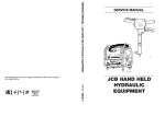
1
TA54
HYDRAULIC
TAMPER
WARNING
To avoid serious injury or death
Read the Manual
Wear Eye
Protection
SAFETY, OPERATION AND MAINTENANCE
SERVICE MANUAL
Wear Ear
Protection
Wear Dust Mask
47351
Copyright © 2003, The Stanley Works
OPS/SVCE USA
16826 12/2003 Ver 2
Stanley Hydraulic Tools
3810 SE Naef Road
Milwaukie OR 97267-5698
503-659-5660
FAX 503-652-1780
www.stanley-hydraulic-tools.com
TABLE OF CONTENTS
Safety Symbols and Precautions ..................................................................... 4, 5
Tool Stickers and Tags ........................................................................................ 6
Hydraulic Hose Requirements ........................................................................... 7
HTMA Requirements ........................................................................................... 8
Operation ............................................................................................................. 9
Equipment Protection and Care ........................................................................ 10
Troubleshooting ................................................................................................. 11
Specifications .................................................................................................... 13
Accessories ....................................................................................................... 13
Service Tools ..................................................................................................... 13
Service ............................................................................................................... 14
Parts Illustration ................................................................................................. 18
Parts List ............................................................................................................ 19
Warranty ............................................................................................................. 20
SERVICING THE STANLEY TAMPER: This manual contains safety, operation, and routine maintenance
instructions. Stanley Hydraulic Tools recommends that servicing of hydraulic tools, other than routine
maintenance, must be performed by an authorized and certified dealer. Please read the following
warning.
WARNING
SERIOUS INJURY OR DEATH COULD RESULT FROM THE IMPROPER REPAIR OR SERVICE OF THIS TOOL.
REPAIRS AND / OR SERVICE TO THIS TOOL MUST ONLY BE
DONE BY AN AUTHORIZED AND CERTIFIED DEALER.
For the nearest authorized and certified dealer, call Stanley Hydraulic Tools at one of the numbers listed
on the back of this manual and ask for a Customer Service Representative.
3
SAFETY SYMBOLS
Safety symbols and signal words, as shown below, are used to emphasize all operator, maintenance and repair
actions which, if not strictly followed, could result in a life-threatening situation, bodily injury or damage to equipment.
This is the safety alert symbol. It is used to alert you to potential personal
injury hazards. Obey all safety messages that follow this symbol to avoid
possible injury or death.
DANGER
This safety alert and signal word indicate an imminently hazardous situation which, if not avoided, will result in death or serious injury.
WARNING
This safety alert and signal word indicate a potentially hazardous situation
which, if not avoided, could result in death or serious injury.
CAUTION
This safety alert and signal word indicate a potentially hazardous situation
which, if not avoided, may result in minor or moderate injury.
This signal word indicates a potentially hazardous situation which, if not
avoided, may result in property damage.
NOTICE
This signal word indicates a situation which, if not avoided, will result in
damage to the equipment.
IMPORTANT
This signal word indicates a situation which, if not avoided, may result in
damage to the equipment.
Always observe safety symbols. They are included for your safety and for the protection of the tool.
LOCAL SAFETY REGULATIONS
Enter any local safety regulations here. Keep these instructions in an area accessible to the operator and maintenance personnel.
4
SAFETY PRECAUTIONS
Tool operators and maintenance personnel must always comply with the safety
precautions given in this manual and on the stickers and tags attached to the tool
and hose.
To avoid serious injury or death
These safety precautions are given for your safety. Review them carefully before
operating the tool and before performing general maintenance or repairs.
Read the Manual
Wear Ear
Protection
Supervising personnel should develop additional precautions relating to the specific
work area and local safety regulations. If so, place the added precautions in the
space provided on page 4.
Wear Eye
Protection
The TA54 Hydraulic Tamper will provide safe and dependable service if operated in
accordance with the instructions given in this manual. Read and understand this
manual and any stickers and tags attached to the tool and hoses before operation.
Failure to do so could result in personal injury or equipment damage.
Wear Dust Mask
47351
• Operator must start in a work area without bystanders. The operator must be familiar with all prohibited work areas such
as excessive slopes and dangerous terrain conditions.
• Establish a training program for all operators to ensure safe operation.
• Do not operate the tool unless thoroughly trained or under the supervision of an instructor.
• Always wear safety equipment such as goggles, ear, head protection, and safety shoes at all times when operating the
tool. Never wear loose clothing that can get entangled in the working parts of the tool.
• Do not inspect or clean the tool while the hydraulic power source is connected. Accidental engagement of the tool can
cause serious injury.
• Supply hoses must have a minimum working pressure rating of 2500 psi/175 bar.
• Be sure all hose connections are tight.
• The hydraulic circuit control valve must be in the "OFF" position when coupling or uncoupling the tool. Wipe all couplers
clean before connecting. Use only lint-free cloths. Failure to do so may result in damage to the quick couplers and
cause overheating of the hydraulic system.
• Do not operate the tool at oil temperatures above 140°F/60°C. Operation at higher oil temperatures can cause operator
discomfort and may damage the tool.
• Do not operate a damaged, improperly adjusted, or incompletely assembled tool.
• Know the location of buried or covered services before starting your work.
• To avoid personal injury or equipment damage, all tool repair, maintenance and service must only be performed by
authorized and properly trained personnel.
• Do not exceed the rated limits of the tool or use the tool for applications beyond its design capacity.
• Always keep critical tool markings, such as lables and warning stickers legible.
• Always replace parts with replacement parts recommended by Stanley Hydraulic Tools.
• Without the use of of non-conductive accessories, this tool is not for use near energized lines. Failure to comply with
this warning could result in serious personal injury.
• Do not overreach. Maintain proper footing and balanace at all times.
• Use care when handling the tamper. Do not carry the tool by the hoses.
5
TOOL STICKERS & TAGS
05152
03783
GPM Decal
Stanley Hydraulic Tools
3810 SE Naef Road
Milwaukie, OR 97267 USA
Model No.
TA54
14908
05152
Stanley Logo Decal
3-9 GPM / 11-34 LPM
DO NOT EXCEED 2000 PSI / 140 BAR
DO NOT EXCEED SPECIFIED FLOW OR PRESSURE
USE CLOSED-CENTER TOOL ON CLOSED-CENTER
SYSTEM. USE OPEN-CENTER TOOL ON OPEN-CENTER
SYSTEM. CORRECTLY CONNECT HOSES TO TOOL “IN”
AND “OUT” PORTS. IMPROPER HANDLING, USE OR OTHER
MAINTENANCE OF TOOL COULD RESULT IN A LEAK, BURST
OR OTHER TOOL FAILURE. CONTACT AT A LEAK OR BURST
CAN CAUSE OIL INJECTION INTO THE BODY. FAILURE TO
OBSERVE THESE PRECAUTIONS CAN RESULT IN SERIOUS
PERSONAL INJURY.
14908
Name Tag
03783
D A N G E R
1. FAILURE TO USE HYDRAULIC HOSE LABELED AND CERTIFIED
AS NON-CONDUCTIVE WHEN USING HYDRAULIC TOOLS ON
OR NEAR ELECTRICAL LINES MAY RESULT IN DEATH OR SERIOUS INJURY.
BEFORE USING HOSE LABELED AND CERTIFIED AS NON-CONDUCTIVE ON OR NEAR ELECTRIC LINES BE SURE THE HOSE IS
MAINTAINED AS NON-CONDUCTIVE. THE HOSE SHOULD BE
REGULARLY TESTED FOR ELECTRIC CURRENT LEAKAGE IN
ACCORDANCE WITH YOUR SAFETY DEPARTMENT INSTRUCTIONS.
2. A HYDRAULIC LEAK OR BURST MAY CAUSE OIL INJECTION
INTO THE BODY OR CAUSE OTHER SEVERE PERSONAL INJURY.
A
DO NOT EXCEED SPECIFIED FLOW AND PRESSURE FOR
THIS TOOL. EXCESS FLOW OR PRESSURE MAY CAUSE A
LEAK OR BURST.
B
DO NOT EXCEED RATED WORKING PRESSURE OF HYDRAU
LIC HOSE USED WITH THIS TOOL. EXCESS PRESSURE MAY
CAUSE A LEAK OR BURST.
C CHECK TOOL HOSE COUPLERS AND CONNECTORS DAILY
FOR LEAKS. DO NOT FEEL FOR LEAKS WITH YOUR HANDS.
CONTACT WITH A LEAK MAY RESULT IN SEVERE PERSONAL
INJURY.
The safety tag (p/n 15875)
at right is attached to the
tool when shipped from the
factory. Read and understand the safety instructions listed on this tag
before removal. We
suggest you retain this tag
and attach it to the tool
when not in use.
D A N G E R
D DO NOT LIFT OR CARRY TOOL BY THE HOSES. DO NOT
ABUSE HOSE. DO NOT USE KINKED, TORN OR DAMAGED
HOSE.
3. MAKE SURE HYDRAULIC HOSES ARE PROPERLY CONNECTED
TO THE TOOL BEFORE PRESSURING SYSTEM. SYSTEM PRESSURE HOSE MUST ALWAYS BE CONNECTED TO TOOL "IN" PORT.
SYSTEM RETURN HOSE MUST ALWAYS BE CONNECTED TO TOOL
"OUT" PORT. REVERSING CONNECTIONS MAY CAUSE REVERSE
TOOL OPERATION WHICH CAN RESULT IN SEVERE PERSONAL
INJURY.
4. DO NOT CONNECT OPEN-CENTER TOOLS TO CLOSED-CENTER
HYDRAULIC SYSTEMS. THIS MAY RESULT IN LOSS OF OTHER
HYDRAULIC FUNCTIONS POWERED BY THE SAME SYSTEM AND/
OR SEVERE PERSONAL INJURY.
5. BYSTANDERS MAY BE INJURED IN YOUR WORK AREA. KEEP BYSTANDERS CLEAR OF YOUR WORK AREA.
6. WEAR HEARING, EYE, FOOT, HAND AND HEAD PROTECTION.
7. TO AVOID PERSONAL INJURY OR EQUIPMENT DAMAGE, ALL TOOL
REPAIR MAINTENANCE AND SERVICE MUST ONLY BE PERFORMED BY AUTHORIZED AND PROPERLY TRAINED PERSONNEL.
I M P O R TA N T
I M P O R TA N T
READ OPERATION MANUAL AND
SAFETY INSTRUCTIONS FOR THIS
TOOL BEFORE USING IT.
READ OPERATION MANUAL AND
SAFETY INSTRUCTIONS FOR THIS
TOOL BEFORE USING IT.
USE ONLY PARTS AND REPAIR
PROCEDURES APPROVED BY
STANLEY AND DESCRIBED IN THE OPERATION
MANUAL.
USE ONLY PARTS AND REPAIR
PROCEDURES APPROVED BY
STANLEY AND DESCRIBED IN THE OPERATION
MANUAL.
TAG TO BE REMOVED ONLY BY
TOOL OPERATOR.
TAG TO BE REMOVED ONLY BY
TOOL OPERATOR.
SEE OTHER SIDE
SEE OTHER SIDE
SAFETY TAG P/N 15875 (shown smaller then actual size)
6
HYDRAULIC HOSE REQUIREMENTS
HOSE TYPES
Hydraulic hose types authorized for use with Stanley Hydraulic Tools are as follows:
! Certified non-conductive
" Wire-braided (conductive)
$ Fabric-braided (not certified or labeled non-conductive)
Hose ! listed above is the only hose authorized for use near electrical conductors.
Hoses " and $ listed above are conductive and must never be used near electrical conductors.
HOSE SAFETY TAGS
To help ensure your safety, the following DANGER tags are attached to all hose purchased from Stanley Hydraulic
Tools. DO NOT REMOVE THESE TAGS.
If the information on a tag is illegible because of wear or damage, replace the tag immediately. A new tag may be
obtained from your Stanley Distributor.
D A N G E R
D A N G E R
1 FAILURE TO USE HYDRAULIC HOSE LABELED AND CERTIFIED AS NON-CONDUCTIVE WHEN
USING HYDRAULIC TOOLS ON OR NEAR ELECTRIC LINES MAYRESULT IN DEATH OR SERIOUS
INJURY.
FOR PROPER AND SAFE OPERATION MAKE SURE THAT YOU HAVE BEEN PROPERLY TRAINED IN
CORRECT PROCEDURES REQUIRED FOR WORK ON OR AROUND ELECTRIC LINES.
3. DO NOT EXCEED HOSE WORKING PRESSURE OR ABUSE HOSE. IMPROPER USE OR HANDLING
OF HOSE COULD RESULT IN BURST OR OTHER HOSE FAILURE. KEEP HOSE AS FAR AWAY AS
POSSIBLE FROM BODY AND DO NOT PERMIT DIRECT CONTACT DURING USE. CONTACT AT THE
BURST CAN CAUSE BODILY INJECTION AND SEVERE PERSONAL INJURY.
4. HANDLE AND ROUTE HOSE CAREFULLY TO AVOID KINKING, ABRASION, CUTTING, OR CONTACT
WITH HIGH TEMPERATURE SURFACES. DO NOT USE IF KINKED. DO NOT USE HOSE TO PULL OR
LIFT TOOLS, POWER UNITS, ETC.
2. BEFORE USING HYDRAULIC HOSE LABELED AND CERTIFIED AS NON-CONDUCTIVE ON OR
NEAR ELECTRIC LINES. WIPE THE ENTIRE LENGTH OF THE HOSE AND FITTING WITH A CLEAN
DRY ABSORBENT CLOTH TO REMOVE DIRT AND MOSISTURE AND TEST HOSE FOR MAXIMUM
ALLOWABLE CURRENT LEAKAGE IN ACCORDANCE WITH SAFETY DEPARTMENT
INSTRUCTIONS.
5. CHECK ENTIRE HOSE FOR CUTS CRACKS LEAKS ABRASIONS, BULGES, OR DAMAGE TO
COUPLINGS IF ANY OF THESE CONDITIONS EXIST, REPLACE THE HOSE IMMEDIATELY. NEVER
USE TAPE OR ANY DEVICE TO ATTEMPT TO MEND THE HOSE.
6. AFTER EACH USE STORE IN A CLEAN DRY AREA.
SEE OTHER SIDE
SEE OTHER SIDE
SIDE 1
3
D O N O T R E M O V E T H I S TA G
D O N O T R E M O V E T H I S TA G
THE TAG SHOWN BELOW IS ATTACHED TO "CERTIFIED NON-CONDUCTIVE" HOSE
SIDE 2
(shown smaller than actual size)
D A N G E R
D A N G E R
1 DO NOT USE THIS HYDRAULIC HOSE ON OR NEAR ELECTRIC LINES. THIS HOSE IS NOT
LABELED OR CERTIFIED AS NON-CONDUCTIVE. USING THIS HOSE ON OR NEAR ELECTRICAL
LINES MAY RESULT IN DEATH OR SERIOUS INJURY.
5. CHECK ENTIRE HOSE FOR CUTS CRACKS LEAKS ABRASIONS, BULGES, OR DAMAGE TO
COUPLINGS IF ANY OF THESE CONDITIONS EXIST, REPLACE THE HOSE IMMEDIATELY. NEVER
USE TAPE OR ANY DEVICE TO ATTEMPT TO MEND THE HOSE.
2. FOR PROPER AND SAFE OPERATION MAKE SURE THAT YOU HAVE BEEN PROPERLY TRAINED IN
CORRECT PROCEDURES REQUIRED FOR WORK ON OR AROUND ELECTRIC LINES.
6. AFTER EACH USE STORE IN A CLEAN DRY AREA.
3. DO NOT EXCEED HOSE WORKING PRESSURE OR ABUSE HOSE. IMPROPER USE OR HANDLING
OF HOSE COULD RESULT IN BURST OR OTHER HOSE FAILURE. KEEP HOSE AS FAR AWAY AS
POSSIBLE FROM BODY AND DO NOT PERMIT DIRECT CONTACT DURING USE. CONTACT AT
THE BURST CAN CAUSE BODILY INJECTION AND SEVERE PERSONAL INJURY.
4. HANDLE AND ROUTE HOSE CAREFULLY TO AVOID KINKING, CUTTING, OR CONTACT WITH
HIGH TEMPERATURE SURFACES. DO NOT USE IF KINKED. DO NOT USE HOSE TO PULL OR LIFT
TOOLS, POWER UNITS, ETC.
D O N O T R E M O V E T H I S TA G
D O N O T R E M O V E T H I S TA G
THE TAG SHOWN BELOW IS ATTACHED TO "CONDUCTIVE" HOSE.
SEE OTHER SIDE
SEE OTHER SIDE
SIDE 1
SIDE 2
(shown smaller than actual size)
HOSE PRESSURE RATING
The rated working pressure of the hydraulic hose must be equal to or higher than the relief valve setting on the
hydraulic system.
7
HTMA REQUIREMENTS
Tool Category
Hydraulic System
Requirements
20Lpm at 138bar
BHTMA CATEGORY
30Lpm at 138bar
BHTMA CATEGORY
Type I
Type II
40Lpm at 138bar
EHTMA CATEGORY
Type III
4-6gpm
7-9gpm
10.5-11.6 gpm
11-13 gpm
(at the power supply outlet)
2000 psi
2000 psi
2000 psi
2000 psi
System relief valve setting
2100-2250 psi
Flow rate
Tool Operating Pressure
(at the power supply outlet)
Maximum back pressure
(at tool end of the return hose)
(15-23 lpm)
(26-34 lpm)
(138 bar)
(138 bar)
2100-2250 psi
(145-155 bar)
200 psi
Measured at a max. fluid viscosity of: 400 ssu*
(138 bar)
2100-2250 psi
(42-49 lpm)
(138 bar)
2100-2250 psi
(145-155 bar)
(145-155 bar)
(145-155 bar)
200 psi
200 psi
200 psi
(14 bar)
(14 bar)
(36-44 lpm)
(14 bar)
(14 bar)
(at min. operating temperature)
(82 centistokes)
(82 centistokes)
400 ssu*
400 ssu*
400 ssu*
Temperature
Sufficient heat rejection capacity
to limit max. fluid temperature to:
140° F (60° C)
140° F (60° C)
140° F (60° C)
140° F (60° C)
Min. cooling capacity
at a temperature difference of
between ambient and fluid temps
3 hp (2.24 kW)
40° F (22° C)
5 hp (3.73 kW)
40° F (22° C)
6 hp (4.47 kW)
40° F (22° C)
7 hp (5.22 kW)
40° F (22° C)
25 microns
18 gpm (68 lpm)
25 microns
25 microns
25 microns
30 gpm (114 lpm) 35 gpm (132 lpm) 40 gpm (151 lpm)
100-400 ssu*
100-400 ssu*
(82 centistokes)
(82 centistokes)
(at max. expected ambient temperature)
NOTE: Do not operate the tool at oil
° F (60° C). Operation
temperatures above 140
at higher temperatures can cause operator
discomfort at the tool.
Filter
Min. full-flow filtration
Sized for flow of at least:
(For cold temp. startup and max. dirt-holding
capacity)
Hydraulic fluid
Petroleum based
(premium grade, anti-wear, non-conductive)
Viscosity
(at min. and max. operating temps)
(20-82 centistokes)
NOTE: When choosing hydraulic fluid, the
expected oil temperature extremes that will be
experienced in service determine the
most suitable temperature viscosity
characteristics. Hydraulic fluids with a viscosity
index over 140 will meet the requirements over
a wide range of operating temperatures.
(20-82 centistokes)
100-400 ssu*
(20-82 centistokes)
100-400 ssu*
(20-82 centistokes)
NOTE: These are general hydraulic system requirements. See tool Specification page for tool
specific requirements.
8
OPERATION
PREOPERATION PROCEDURES
NOTE:
Partially depressing the trigger allows the tool
to operate at a slow speed, making it easy to
start the tamper on the surface to compacted.
PREPARATION FOR INITIAL USE
The tool, as shipped, has no special unpacking or assembly
requirements prior to usage. Inspection to assure the tool
was not damaged in shipping and does not contain packing
debris is all that is required.
4. Guide the tamper using both hands. One on the On/Off
valve trigger and the other at the tapered section at the end
of the handle tube.
5. When back-filling a deep hole, compact (tamp) the backfill after a maximum of 6 inches/15 cm of material is added to
the hole. This will ensure maximum compaction of the filled
hole and minimize any setting that may occur.
CHECK HYDRAULIC POWER SOURCE
1. Using a calibrated flowmeter and pressure gauge, check
that the hydraulic power source develops a flow of 3-9 gpm/
11-34 lpm at 1000-2000 psi/70-140 bar.
COLD WEATHER OPERATION
2. Make certain the hydraulic power source is equipped with
a relief valve set to open at 2250 psi/155 bar maximum.
If the tool is to be used during cold weather, preheat the
hydraulic fluid at low engine speed. When using the normally recommended fluids, fluid temperature should be at or
above 50° F/10° C (400 ssu/82 centistokes) before use.
3. Check that the hydraulic circuit matches the tool for opencenter (OC) operation.
CHECK TOOL
STORAGE
1. Make sure all tool accessories are correctly installed.
Failure to install tool accessories properly can result in
damage to the tool or personal injury.
1. Disconnect the tool from the hydraulic power source.
2. Remove the tool bit and spray the chuck area with WD40™ inside and out.
2. There should be no signs of leaks.
3. Wipe clean and store in a clean, dry place.
3. The tool should be clean, with all fittings and fasteners
tight.
CHECK TRIGGER MECHANISM
1. Check that the trigger operates smoothly and is free to
travel between the "ON" and "OFF" positions.
OPERATING PROCEDURES
1. Observe all safety precautions.
2. Place the tamper on the surface to be compacted.
3. Squeeze the trigger to start the tamper.
WARNING
The tamper will rise quickly when first turned on. Do
not stand over or place any part of your body on top
of the tamper. Wear safety shoes.
9
EQUIPMENT PROTECTION & CARE
NOTICE
In addition to the Safety
Precautions in this manual,
observe the following for
equipment protection and
care.
• Make sure all couplers are wiped clean before connection.
• The hydraulic circuit control valve must be in the “OFF” position when coupling or uncoupling
hydraulic tools. Failure to do so may result in damage to the quick couples and cause overheating
of the hydraulic system.
• Always store the tool in a clean dry space, safe from damage or pilferage.
• Make sure the circuit PRESSURE hose (with male quick disconnect) is connected to the “IN” port.
The circuit RETURN hose (with female quick disconnect) is connected to the opposite port. Do not
reverse circuit flow. This can cause damage to internal seals.
• Always replace hoses, couplings and other parts with replacement parts recommended by Stanley
Hydraulic Tools. Supply hoses must have a minimum working pressure rating of 2500 psi/172 bar.
• Do not exceed the rated flow (see Specifications) in this manual for correct flow rate and
model number. Rapid failure of the internal seals may result.
• Always keep critical tool markings, such as warning stickers and tags legible.
• Tool repair should be performed by experienced personnel only.
• Make certain that the recommended relief valves are installed in the pressure side of the system.
• Do not use the tool for applications for which it was not intended.
10
TROUBLESHOOTING
Tool does not run.
Tool does not compact
effectively.
Tool operates slow.
Power unit not functioning.
Check power unit for proper flow
and pressure 3-9gpm/11-34 lpm
at 1000-2000 psi/70-140 bar.
Couplers or hoses blocked.
Remove restriction.
Presssure and return line hoses
reversed at ports.
Be sure hoses are connected to
their proper ports.
Mechanical failure.
Have inspected and repaired by
authorized dealer.
Backpressure too high.
Check hydraulic system for
excessive backpressure over
250 psi/17 bar measure at the end
of the tool operating hoses.
Power unit not functioning.
Check power unit for proper flow
and pressure 7-9gpm/26-34 lpm,
1500 psi/103 bar.
Couplers or hose blocked.
Remove restriction.
Backpressure too high.
Check hydraulic system for
excessive backpressure over
250 psi/17 bar measure at the end
of the tool operating hoses.
Fluid too hot
(above 140°F / 60°C)
Fluid too cold
(below 60°F / 15.5°C)
Provide cooler to maintain proper
oil temperature. Bypass cooler
to warm up oil, or provide cooler
to maintain proper temperature.
Tamper shoe too large for soil
conditions.
Use smaller shoe for backfilling operations (p/n 01849).
Low oil flow from power unit.
Check power source for proper
flow.
High backpressure.
Check hydraulic system for
excessive backpressure and
correct as required.
Couplers or hoses blocked.
Remove restrictions.
Fluid too hot
(above 140°F / 60°C)
Fluid too cold
(below 60°F / 15.5°C)
Provide cooler to maintain proper
oil temperature. Bypass cooler
to warm up oil, or provide cooler
to maintain proper temperature.
11
TROUBLESHOOTING
Tamper gets hot.
Hot oil going through tool
Check power unit. Be sure flow
rate is not too high causing
excess oil to go through the
relief valve. Provide cooler to
maintain proper oil temperature
(100-130°F/38-54°C). Eliminate
flow control devices. Do Not
Exceed Recommended Flow.
Oil leakage on pison rod
Lower piston seal failure.
Replace seal and wiper, piston
and nose as required.
Oil leakage around trigger.
Valve spool seal failure.
Replace seals.
Oil leakage around spool end
caps.
O-Ring failure.
Replace O-Rings.
Piston extends but does not
retract (reciprocate).
Presure and return reversed.
Correct the proper flow direction
at power unit or tool.
Tool not assembled correctly.
Review service instructions for
proper assembly or contact an
authorized Stanley Hydraulic
Tools distributor.
Also check the following:
1. Flow sleeve lined up correctly
with locating pin.
2. Oil tubes reveresed at On/Off
valve.
3. Front sleeve in correctly.
4. Thrust bridge washer in correctly.
Backpressure too high
12
Check hydraulic system for
excessive backpressure over
250 psi/17 bar measure at the end
of the tool operating hoses.
SPECIFICATIONS
RTANTIMPORTANT
Oil Flow Range .......................................................................................................................................... 3-9 gpm/11-34 lpm
Pressure Range ............................................................................................................................. 1000-2000 psi/70-140 Bar
Length ................................................................................................................................................................... See Below
Weight ............................................................................................................................................................. 25 lbs/11.3 kg
Porting ......................................................................................................... 1/2 in. SAE O-Ring Port or 3/8 Pipe Hose Ends
Couplers ..................................................................................................... HTMA/EHTMA Flush Face Type Male & Female
System Type .................................................................................................................................... HTMA Type I and Type II
Handle Length
3 Foot
System Type
No Valve
Valve in Handle
66 inches/167 cm
Mid-Valve
55 inches/139 cm
O.C./C.C.
O.C./C.C.
O.C
ACCESSORIES
Description
Part No.
Kidney Shoe .............................................................................................................................................................. 00833
Round Shoe, 6-inch Diameter ..................................................................................................................................... 00840
Rectangular Shoe ....................................................................................................................................................... 01070
Square Shoe, 8-inch x 8-inch ..................................................................................................................................... 01081
Square Shoe, 6-inch x 6-inch ..................................................................................................................................... 08252
8 Ft Hose (2 required) ................................................................................................................................................ 35784
45° Elbow -8 SAE Male x -8 JIC Male .......................................................................................................................350000
In-Line Valve Assembly O.C./C.C. .............................................................................................................................. 38632
SERVICE TOOLS
Tamper Sleeve Tool ..................................................................................................................................................... 01120
Sleeve Installation Wrench ......................................................................................................................................... 01949
O-Ring Tool Kit ........................................................................................................................................................... 04337
13
SERVICE
Pull the valve body away from the handle assembly.
PRIOR TO DISASSEMBLY
Clean exterior of tool.
Obtain Seal Kit, (Part Number 02030), for no-valve models, or
(Part Number 02032), for valve-in-handle models, so you can
replace all seals exposed during disassembly. Note orientation of seals before removing them. Install new seals in the
same way.
NOTE:
Refer to Parts List Illustration for location of parts.
TO REMOVE THE HANDLE
ASSEMBLY
1. Place the tamper in a vise with soft jaws, clamping on the
large flat faces of block and tube assembly with the handle
assembly to the right and the trigger on the valve-in-handle
models in the up position.
2. No-valve Models.
a. Remove the four oval head capscrews securing the hose
guides to the handle and remove the guides.
b. Remove the four 5/16-18 x 1-1/4 inch/32 mm long
capscrews and washers securing the handle tube to the
lower assembly and separate assemblies.
c. On all models, remove the four 5/16-18 x 1-1/4 inch/32 cm
long capscrews and washers securing the handle assembly
to the lower assembly and slide the handle off over the tubes
or hoses.
d. Remove the oil tubes or hoses and fittings as required.
TO DISASSEMBLE THE VALVE
ASSEMBLY
1. On mid-valve models, remove the button head machine
screw from the end of the on-off spool. Drive the 5/32 x 1
inch/4 mm x 25 mm roll pin from valve body assembly and
pull the valve spool with the trigger attached out of the spool
bore. Drive out the 1/8 x 7/8 inch/3 mm x 22 mm roll pin to
remove the spool from the trigger. Slide the spring off of the
spool.
Carefully remove the a-rings from the valve spool bore using
o-ring service tools.
2. On end-valve models, drive the two 5/32 inch/4 mm
diameter roll pins out of the trigger. Then remove the trigger,
spring and valve spool from the valve body.
Carefully remove the a-rings from the valve spool bore before
using o-ring service tools.
TO DISASSEMBLE THE LOWER
ASSEMBLY (VIEW A)
c. Remove the hose assembly from two fittings on the lower
assembly and pull hose out of the handle assembly.
3. Valve-in-handle Models.
a. On mid-valve models, remove the four flat head screws
securing the valve body to the handle tube and pull the valve
body away from the handle assembly.
On mid-valve models remove the eight capscrews securing
the upper handle tube to the valve body and hose guides.
Slide the upper handle tube off to access the upper hose
assemblies.
b. On end-valve models, place a wrench across the flat
portion of the on-off valve body, slide the protective cover off
of the retaining nut and loosen the nut with a 2-1/8 inch
wrench.
1. Remove the 7/16-20 x 1-1/2 inch/38 mm long capscrew
and lockwasher securing the tamper shoe to the piston. Tap
on the top of the tamper shoe with a soft face hammer to
remove it from the piston taper.
If the tamper shoe is not removed easily as above, thread the
retaining screw three fourths of the way in and tap on its
head with a hammer while pulling on the shoe.
2. Loosen the jam nut and unscrew the nose from the block
and tube assembly.
3. Remove the rod wiper and felt washer from the lower end
of the nose.
4. Remove the rod seal from the nose by first removing the
retaining ring.
14
SERVICE
5. Remove the cushion and two o-rings from the opposite
end of the nose. Always install new seals and o-rings during
assembly.
NOTE:
The spool should move freely in its bore without
binding.
6. Pull the piston from the block and tube assembly. The
front sleeve and thrust bridge washer can be removed with
the piston.
2. Place the block and tube assembly in a bench vise with
soft jaws and clamp on the large flat faces of the block.
7. Remove the back sleeve and oil tube from the block and
tube assembly by using service tool, (Part Number 01120),
or a length of 3/8-16 Redi-Bolt threaded into the end of the oil
tube.
3. If the flow sleeve is still in position on the roll pin in the
bottom of the block and tube assembly bore, proceed to step
(6). If the flow sleeve has shifted position or has been
removed, it must be repositioned using service tool, (Part
Number 01949), Sleeve Installation Wrench.
NOTE:
Remove the flow sleeve by placing a hooked tool into
the 5/16-inch holes in the lower end of the sleeve. Be
careful not to damage the bore.
4. Insert the flow sleeve into the block and tube assembly
slotted end first. Note position of the doweling hole in the end
of the flow sleeve and the pin in the bottom of the block and
tube bore. Align these features as the flow sleeve is inserted.
8. Remove the reversing spool by removing the two end
caps.
5. Place the projection on the end of service tool, (Part
Number 01949), Sleeve Installation Wrench in the slot on the
end of the face of the flow sleeve. Push the flow sleeve into
place, rotating back and forth as required to align the pin,
until the groove in the installation wrench is flush with the
end of the block and tube assembly.
NOTE:
The insert pressed into the block and tube assembly for
the forward/reverse spool is not serviceable. It should
be tight in its bore with the slot on either end perpendicular to the block and tube center line.
IMPORTANT
TAMPER REASSEMBLY
Do not force the flow sleeve into place or attempt
further assembly without the flow sleeve in the
proper position.
PRIOR TO REASSEMBLY
Clean all parts with a degreasing solvent.
6. Insert the oil tube (small end first) into the counterbored
end of the back sleeve. Loosely thread, (Part Number
01120), Tamper Sleeve Tool into the oil tube thread. Place a
new o-ring into the groove on the end face of the oil tube and
retained with grease. Replace the two oil control seals in the
grooves of the back sleeve (grooves with multiple holes).
Inspect all parts for obvious wear and damage.
Ensure that all seals exposed during disassembly are
replaced. Refer to the parts list at the back of this manual for
the applicable repair and seal kit.
7. Slide this entire assembly into the flow sleeve, and remove
the Tamper Sleeve Tool by pushing firmly as you rotate it
counterclockwise.
Apply clean grease or o-ring lubricant to all parts during
reassembly.
Refer to the parts list at the back of this manual for parts
location.
8. Insert the piston (tapered end first) into large end of the
front sleeve. (The four grooves on the front sleeve 0.0. are
towards the large end of the piston.)
REASSEMBLY
Insert this assembly into the flow sleeve using your fingers to
push the front sleeve into place. (The hollow end of Part
Number 01120 Tamper Sleeve Tool may be used to push the
front sleeve into place.)
LOWER ASSEMBLY
1. Install one of the end caps (with o-ring) on the block and
tube assembly, then install the reversing spool. Install the
remaining end cap and o-ring. Tighten the end caps securely.
15
SERVICE
9. Install the bridge, washer (beveled side out) over the piston
and against the front sleeve and flow sleeve faces.
e. Depress the trigger and place a small drop of #242 Loctite
on the thread of the button head machine screw and tighten
securely into the valve spool.
10. Replace the seals in the nose as follows:
IMPORTANT
IMPORTANT
a. Press the rod seal (lip side in) into the lower end of the
nose. Make sure the seal is positioned against the inner
shoulder of the nose.
Do not allow Loctite on the outside diameter of the
valve spool.
b. Install the seal washer in the nose. Push it firmly against
the rod seal.
c. Secure the rod seal and seal washer in place by installing
the spirolox retaining ring.
2. Valve-in-handle Tampers.
a. Replace the o-rings within the spool bore.
d. Install the felt washer in the nose, then install the rod
wiper (lip side out). The edge of the wiper must be flush with
the end of the nose.
b. Insert the valve spool assembly (small end first) through
the valve body, from the side opposite the trigger.
e. Install the 1/8 x 1 inch/3 mm x 25 mm 1.0. o-ring and
cushion, chamfered/notched side out, into the counter-bore
on the threaded end.
c. Place the valve spring on the valve spool projecting
through the trigger side, followed by the trigger.
f. Install the 1/16 x 1-3/4 inch/1.5 mm x 44.5 mm I.D. o-ring
in the outside groove of the nose.
d. Align the trigger with the corresponding holes in the valve
body using a 1/8 inch or 5/32 inch/3 mm or 4 mm diameter
punch, and drive the 5/32 inch/4 mm diameter roll pins into
place.
11. Install the nose, as assembled above, over the piston and
screw into the block and tube assembly and tighten securely.
HANDLE ASSEMBLY, OIL TUBES
AND VALVE ASSEMBLY
12. Replace the jam nut and tighten securely.
13. Install the tamper shoe on the piston rod and secure with
the 7/16-20 x 1-1/2 inch/38 mm long capscrew.
1. No-Valve Tampers.
a. Insert the hose assembly through the tube end of the
handle assembly, female fittings first.
VALVE ASSEMBLY
1. Mid-valve Tampers.
a. Replace the o-rings within the spool bore.
b. Attach the hose assembly to the fittings on the block and
tube assembly, attaching the hose painted red to the port
marked “IN”.
b. Attach the valve spool to the trigger using a 1/8 x 7/8 inch/
3 mm x 22 mm roll pin.
c. Attach the handle assembly to the block and tube assembly with four 5/16-18 x 1-1/4 inch/32 mm long capscrews and
washer.
c. Place the valve spring over the valve spool and lubricate its
O.D.
d. Install hose guides and secure with the four oval head
screws.
d. Push the valve spool through the trigger side of the valve
body bore, and secure the trigger to the valve body with a 5/
32 inch diameter x 1 inch/4 mm x 25 mm roll pin through the
trigger pivot.
2. Mid-valve Tampers.
a. Insert plain ends of oil tubes into the tube fittings on the
block and tube assembly and secure.
16
SERVICE
b. Install the handle assembly over the oil tubes and secure
to the block and tube assembly with four 5/16-18 x 1-1/4
inch/32 mm long capscrews and lockwashers.
c. Place rubber tube retainer over the oil tubes. Make sure
the tubes are not twisted.
d. Install new a-rings in the oil tube ports of the valve body.
e. Insert the valve assembly into the handle assembly
making sure the oil tubes slide into the valve body ports.
NOTE:
The oil tube port opposite the trigger should connect
the tube marked “IN” at the block and tube assembly.
f. Secure the valve assembly to handle assembly with the
two 1/4-20 and two 5/16-18 flat head screws using #242
Loctite to secure the threads.
3. Valve-in-handle Tamper.
a. Insert the plain ends of the oil tubes into the tube fittings
on the block and tube assembly.
b. Install the handle assembly over the oil tubes and secure
to the block and tube assembly with four 5/16-18 x 1-1/4
inch/32 mm long capscrews and lockwashers.
c. Install new a-rings in the oil tube ports of the body.
d. Push the on-off valve assembly over the oil tubes until
mating with the handle tube flare.
NOTE:
The pressure oil tube is located on the side opposite
the trigger and should correspond to the “IN” port on
the block and tube assembly.
e. Apply #242 Loctite to the valve body threads. Place a
wrench across the flat area of the valve body and tighten the
tube nut to 200 Ib ft/270 Nm with a 2-1/8 inch wrench.
Slide the plastic cover in place over the tube nut.
IMPORTANT
Do not allow the valve body to rotate relative to the
tamper lower assembly. This will avoid twisting the
oil tubes inside the handle assembly.
17
PARTS ILLUSTRATION
18
PARTS LIST
ITEM
QTY PART NO.
1
2
3
4
5
6
7
8
9
10
11
12
13
14
15
16
17
18
19
20
21
22
23
24
25
26
27
28
29
30
31
32
33
34
35
36
37
38
39
1
1
1
1
1
1
1
1
1
1
1
1
1
1
1
1
1
1
2
1
1
1
1
1
1
1
2
1
2
2
1
1
1
2
2
2
1
2
2
40
41
42
43
44
45
46
47
1
2
1
4
4
1
2
2
48
49
1
1
01038
00823
00834
01262
14883
01795
14891
14884
04902
08434
15016
00833
00825
00845
01036
00940
00806
14886
29690
00927
01037
04525
00114
04097
04480
04897
07627
14908
350000
00175
35036
05152
07737
35784
07738
01003
38631
13568
13567
38632
38629
00936
24069
00144
00145
00819
06533
14882
14885
34684
03783
DESCRIPTION
Thrust Bridge Washer
Cushion
O-ring
O-ring
Nose
Jam Nut
Seal
Seal Washer
Retaining Ring, Spirolox
Felt Washer
Rod Wiper
Shoe
Lockwasher
Capscrew
Flow Sleeve
O-ring
Oil Tube
Piston
Oil Control Seal
Back Sleeve
Front Sleeve
Trigger (model TA54103 only)
Roll Pin (model TA54103 only)
Spring (model TA54103 only)
Valve Spool (model TA54103 only)
Valve Body Assy (model TA54103 only)
O-ring
Name Tag
45° Elbow (model TA54603A only)
O-ring
Hose Block (models TA54603 & TA54603A only)
Sticker, Stanley Logo
Handle Assy (incl Jam Nut)
Hose Assy (models TA54603A only)
Oil Tube
Button (model TA54603A only)
Valve Spool (model TA54603A only)
Back-up Ring (model TA54603A only)
O-Ring (model TA54603A only)
In-line Valve Assy (incl items 36-40) (model TA54603A only)
Valve Body Assy (model TA54603A only)
Adapter (modelsTA54603A only)
Coupler Set (model TA54603A only)
Capscrew
Lockwasher
Reversing Spool
O-ring
End Cap
Lower Tamper Assy (Incld items 1-11, 15-21, & 46-48)
Block & Valve Spool Housing
Sticker, GPM
19
Seal Kit Part No. 02030
No Valve Model
Seal Kit Part No. 02032
Valve In Handle Model
ITEM
NO.
3
4
7
10
11
16
19
27
30
46
PART
NO. QTY DESCRIPTION
07245
01262
14891
08434
15016
00940
29690
07627
00175
06533
1
1
1
1
1
1
2
2
2
2
Rod Seal
O-Ring
Seal
Felt Washer
Rod Wiper
O-Ring
Oil Control Seal
O-Ring
O-Ring
O-Ring
WARRANTY
Stanley Hydraulic Tools (hereinafter called “Stanley”), subject to the exceptions contained below, warrants new hydraulic tools for a period of one year from the date of sale
to the first retail purchaser, or for a period of 2 years from the shipping date from Stanley, whichever period expires first, to be free of defects in material and/or
workmanship at the time of delivery, and will, at its option, repair or replace any tool or part of a tool, or new part, which is found upon examination by a Stanley authorized
service outlet or by Stanley’s factory in Milwaukie, Oregon to be DEFECTIVE IN MATERIAL AND/OR WORKMANSHIP.
EXCEPTIONS FROM WARRANTY
NEW PARTS: New parts which are obtained individually are warranted, subject to the exceptions herein, to be free of defects in material and/or workmanship at the time of
delivery and for a period of 6 months after the date of first usage. Seals and diaphragms are warranted to be free of defects in material and/or workmanship at the time of
delivery and for a period of 6 months after the date of first usage or 2 years after the date of delivery, whichever period expires first. Warranty for new parts is limited to
replacement of defective parts only. Labor is not covered.
FREIGHT COSTS: Freight costs to return parts to Stanley, if requested by Stanley for the purpose of evaluating a warranty claim for warranty credit, are covered under
this policy if the claimed part or parts are approved for warranty credit. Freight costs for any part or parts which are not approved for warranty credit will be the responsibility of the individual.
SEALS & DIAPHRAGMS: Seals and diaphragms installed in new tools are warranted to be free of defects in material and/or workmanship for a period of 6 months after the
date of first usage, or for a period of 2 years from the shipping date from Stanley, whichever period expires first.
CUTTING ACCESSORIES: Cutting accessories such as breaker tool bits are warranted to be free of defects in material and or workmanship at the time of delivery only.
ITEMS PRODUCED BY OTHER MANUFACTURERS: Components which are not manufactured by Stanley and are warranted by their respective manufacturers.
a. Costs incurred to remove a Stanley manufactured component in order to service an item manufactured by other manufacturers.
ALTERATIONS & MODIFICATIONS: Alterations or modifications to any tool or part. All obligations under this warranty shall be terminated if the new tool or part is altered or
modified in any way.
NORMAL WEAR: any failure or performance deficiency attributable to normal wear and tear such as tool bushings, retaining pins, wear plates, bumpers, retaining rings and
plugs, rubber bushings, recoil springs, etc.
INCIDENTAL/CONSEQUENTIAL DAMAGES: To the fullest extent permitted by applicable law, in no event will STANLEY be liable for any incidental, consequential or
special damages and/or expenses.
FREIGHT DAMAGE: Damage caused by improper storage or freight handling.
LOSS TIME: Loss of operating time to the user while the tool(s) is out of service.
IMPROPER OPERATION: Any failure or performance deficiency attributable to a failure to follow the guidelines and/or procedures as outlined in the tool’s operation and
maintenance manual.
MAINTENANCE: Any failure or performance deficiency attributable to not maintaining the tool(s) in good operating condition as outlined in the Operation and Maintenance
Manual.
HYDRAULIC PRESSURE & FLOW, HEAT, TYPE OF FLUID: Any failure or performance deficiency attributable to excess hydraulic pressure, excess hydraulic backpressure, excess hydraulic flow, excessive heat, or incorrect hydraulic fluid.
REPAIRS OR ALTERATIONS: Any failure or performance deficiency attributable to repairs by anyone which in Stanley’s sole judgement caused or contributed to the failure
or deficiency.
MIS-APPLICATION: Any failure or performance deficiency attributable to mis-application. “Mis-application” is defined as usage of products for which they were not
originally intended or usage of products in such a matter which exposes them to abuse or accident, without first obtaining the written consent of Stanley. PERMISSION TO
APPLY ANY PRODUCT FOR WHICH IT WAS NOT ORIGINALLY INTENDED CAN ONLY BE OBTAINED FROM STANLEY ENGINEERING.
WARRANTY REGISTRATION: STANLEY ASSUMES NO LIABILITY FOR WARRANTY CLAIMS SUBMITTED FOR WHICH NO TOOL REGISTRATION IS ON RECORD. In
the event a warranty claim is submitted and no tool registration is on record, no warranty credit will be issued without first receiving documentation which proves the sale of
the tool or the tools’ first date of usage. The term “DOCUMENTATION” as used in this paragraph is defined as a bill of sale, or letter of intent from the first retail customer.
A WARRANTY REGISTRATION FORM THAT IS NOT ALSO ON RECORD WITH STANLEY WILL NOT BE ACCEPTED AS “DOCUMENTATION”.
NO ADDITIONAL WARRANTIES OR REPRESENTATIONS
This limited warranty and the obligation of Stanley thereunder is in lieu of all other warranties, expressed or implied including merchantability or fitness for a particular
purpose except for that provided herein. There is no other warranty. This warranty gives the purchaser specific legal rights and other rights may be available
which might vary depending upon applicable law.
20
Stanely Hydraulic Tools
3810 SE Naef Road
Milwaukie, Oregon
503-659-5660 / Fax 503-652-1780
www.stanley-hydraulic-tools.com