1
System A - 100
doepfer
6/12/24/48 dB Low Pass A-108
1. Introduction
Audio Level
Audio
In
A-108
VCF 8
CV 1
CV 2
CV 2
Freq.
CV 3
Res.
CV 3
Feedb.
BP
6dB 12dB 24dB 48dB
LP LP LP LP
Module A-108 is a completely new, unique voltagecontrolled low pass/band pass filter based on the
well-known transistor ladder (Moog ladder).
The module has internally an 8 stage low pass filter
with different slopes available: 6, 12, 18, 24, 30, 36, 42
and 48 dB per octave. In the factory the outputs with 6,
12, 24 and 48 dB are connected to the four low pass
sockets at the front panel. In addition it features an
band pass output (i.e. band pass with transistor ladder).
The module has manual controls for frequency and
resonance available. Resonance can be adjusted
right up to self-oscillation, in which case the filter will
behave like a sine wave oscillator. Three CV inputs
for frequency control are available. Two of them are
eqipped with attenuators.
The A-108 features an external feedback input that
enables the insertion of additional modules into the
feedback path.
The audio input is very sensitive so that distortion
is possible even with normal A-100 levels.
1
A-108 6/12/24/48 dB Low Pass
System A - 100
Controls:
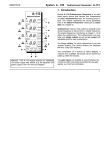
2. VCF 8 - Overview
A-108
VCF 8
1 Freq. :
Manual frequency control
2 CV 2 :
Attenuator for frequency control
voltage at input § / CV2
3 CV 3 :
Attenuator for frequency control
voltage at input § / CV3
6/12/24/48 dB Lowpass
Ouputs
BP
CV 1
Freq.
0
6db LP
CV 2
0
0
0
48db LP Feedb.
➍ ➌
2
Audio
Level
4 Audio Level : Attenuator for audio input !
5 Emph. :
➂
➃
! Audio In :
➄
Audio input to the filter
" BP, 6 db LP ... 48 db LP : Filter outputs
§ CV 1:
Control voltage input for frequency
control, approx. 1V/Oct.
§ CV 2:
Control voltage input for frequency
control, level controlled by 2
§ CV 3:
Control voltage input for frequency
control, level controlled by 3
$ Feedb. :
external feedback input for resonance (audio input)
10
10
Resonance control
In / Outputs:
10
Emph.
0
➊
➁
10
CV 3
➋
➀
10
CV 2
12db LP CV 3
Audio
24db LP In
doepfer
System A - 100
doepfer
3. Controls
Out
6/12/24/48 dB Low Pass A-108
Freq.
Out
1 Freq.
Emph.
Control 1 is used to adjust the filter frequency manually, i.e. the middle frequency fM for the band pass
resp. the cut-off frequency fC for the low pass (see
fig. 1).
Emph.
H The actual filter frequency results from the sum
of the manual control 1 and the external control
inputs CV1 ... CV3.
2 CV 2
Freq.
•
3 CV 3
For voltage control or modulation of the cut-off frequency the CV inputs § can be used. The controls 2
and 3 act as attenuators for the inputs CV2 and CV3
to adjust the control voltage level.
4 Audio Level
This attenuator is used to control the amount of signal
entering the filter audio input !. If the filter’s output
distorts, turn this control down, unless you deliberately
want the distorted sound as a special effect. The filter
audio input is very sensitive so that distortion is possible even with normal A-100 levels. Distortion appears
about from position 5 with normal A-100 audio levels.
fM
Fig. 1:
Freq.
f C Freq.
Frequency response of band and low pass
5 Emph.
Control 3 is used to adjust the filter’s resonance (or
emphasis) - the parameter which emphasises the frequencies around the cut-off point fC. For the band pass
this control changes the bandwidth (see Fig.1-4).
Close to its maximum setting, the filter becomes so
resonant that it goes into self-oscillation, and starts
behaving like a sine wave. You can take advantage
of this effect, and use the VCF as an additional sine
oscillator. Self oscillation will break off at high distortion
levels as the internal feedback signal is drown out by
the distorted audio signal. This feature may intentionally be used to create new sounds. If you want to use
the filter as a sine wave oscillator no audio signal
should be fed in (or control 4 to zero).
3
A-108 6/12/24/48 dB Low Pass
System A - 100
Fig. 2
doepfer
Fig. 4
Fig. 2: Filter response curves (minimal resonance)
Fig. 3
Fig. 3: Filter response curves (middle resonance)
Fig. 4: Filter response curves (high resonance)
For all figures:
a:
b:
c:
d:
e:
4
Band pass
48 dB Low pass
24 dB Low pass
12 dB Low pass
6 dB Low pass
System A - 100
doepfer
6/12/24/48 dB Low Pass A-108
This is the filter’s audio input socket. Patch in the
output from any sound source (eg. VCO, noise generator, subharmonic oscillator, sampler, mixer output).
If you patch one or more modulation sources (e.g.
LFO, ADSR, Random, S&H, Theremin, Ribbon, MIDIto-CV) to these inputs, the cut-off frequency of the
filter will be modulated by the sum of the control
voltages: i.e., the sound color changes according to
the sum of the control voltages put out by the modulators.
" BP
P If you use the VCF as a sine wave oscillator, it
4. In / Outputs
! Audio In
•
6db LP
•
...
•
48db LP
The sockets " are the filter outputs with the filter
types band pass (BP) as well as 6, 12, 24 and 48 dB
low pass (LP).
H You may change the factory settings of the
cut-off slopes (6, 12, 24, 48 db) for the four low
pass outputs (see chapter 6 for details).
§ CV 1 • CV 2 • CV 3
The sockets CV1, CV2 and CV3 are control voltage
inputs to control the filter frequency. Input CV1 has
no attenuator and works approximately to the 1V/
octave standard (not as exactly as the VCOs). Inputs
CV2 and CV3 are equipped with the attenuators 2 and
3 so that the sensitivity of these inputs can be adjusted. With attenuators set to 10 (fully clockwise) the
sensitivity for CV2 and CV3 is about 0.5V/octave.
is recommended to connect the pitch CV to
socket CV1 as this input works approximately
to the 1V/octave standard. Do the same if you
want the filter’s cut-off frequency to track exactly with the pitch of a note.
$ Feedb.
Module A-108 has available an external audio input
for resonance. This socket is normalled, i.e it is
connected to the 48 dB low pass output unless another
signal is patched into this socket. Different modules
can be inserted into the feedback loop (see chapter 5
for examples). E.g. inserting a VCA enables voltage
controlled resonance. It is also possible to feed back
other filter outputs than the 48 dB low pass to obtain
another resonance behaviour.
5
A-108 6/12/24/48 dB Low Pass
System A - 100
5. User Examples
The filter’s cut-off frequency can be modulated in
various ways: e.g. ADSR (A-140, A-141, A-142), LFO
(A-145, A-146, A-147), Sample & Hold (A-148), Random (A-118), Joy-Stick (A-174), Theremin (A-178),
Ribbon (A-198) or via MIDI (A-190/A-191). Many of
these examples can be found in the manuals of the
other filters of the A-100 system.
One special feature of the A-108 is the external
feedback input. This enables the insertion of any
audio processing module into the feedback path. Inserting a VCA leads to voltage controlled resonance.
In this case the control voltage of the VCA works as
voltage control input for the filter’s resonance. Other
modules that are suitable for insertion are e.g. phaser
(A-125), frequency shifter (A-126), waveform processor/distortion (A-116, A-136) or even other filters.
Another example is a filter with voltage controlled
cut-off slope in combination with the voltage controlled mixer A-135 and the morphing controller A-144.
Fig. 5 shows the corresponding patch.
The four low pass outputs (6/12/24/48 dB) of the A-108
are connected to the four audio inputs of the voltage
controlled mixer A-135.
6
doepfer
The levels of the four mixer paths are controlled by the
control voltages coming from the morphing controller
A-144. The audio output signal of the filter with voltage
controlled cut-off slope is available at the output of the
voltage controlled mixer A-135.
The control voltage that is used to control the cut-off
slope is connected to the control voltage input of the
morphing controller A-144. That way it is possible to
sweep the cut-off slope from 6 ... 48dB (fig. 5, 2) with
the control voltage applied to the CV input of the
A-144. In the example the voltage is generated by a
joy stick (A-174) and called “character modulation”. Of
course any other control voltage (e.g. LFO, ADSR,
MIDI-to-CV, Theremin, Random) could be used to
control the “character”, i.e. the cut-off slope. For more
examples please refer to the A-144 user’s manual.
The patch in fig. 5 has these control inputs available:
• Char. Mod.
filter cut-off slope
• Freq. Mod. 1
filter frequency 1 (e.g. ADSR)
• Freq. Mod. 2
filter frequency 2 (e.g. LFO)
If the 48dB low pass output of the A-108 is connected
to the feedback input of the A-108 through a VCA even
the resonance is voltage controlled (= control voltage
of the VCA).
System A - 100
doepfer
A-144
A-135
MC
VC-Mixer
CV Out
Char.
Mod.
1
ext.
CV 1
Audio In
6/12/24/48 dB Low Pass A-108
A-108
VCF 8
Audio Level
Audio
In
1
6dB
LP
2
ext.
CV 2
2
12dB
LP
CV 2
3
ext.
CV 3
3
24dB
LP
CV 3
4
ext.
CV 4
4
48dB
LP
Feedb.
CV
ext.
CV
CV 2
CV 3
Freq.
Mod. 1
Freq.
Mod. 2
Audio Out
VC
Joystick
Audio
Out
1
t
2
100 Hz
1 kHz
10 kHz
Fig. 5: Low pass filter with voltage controlled cut-off slope
7
A-108 6/12/24/48 dB Low Pass
System A - 100
doepfer
6. Changing the assignment of the
four low pass outputs
ment of the filter stages to the outputs. One pair of
jumpers is responsible for each of the filter stages. The
factory setting of the jumpers is marked black.
Only 4 output stages are available as this seems to be
sufficient from our experience. In the factory the 4
outputs are connected to the filter stages with 6, 12, 24
and 48 dB cut-off slope. This is a well-considered
compromise as these outputs generate audible different sounds. E.g. the audible difference between the
48dB and 42dB or between 42dB and 36dB is very
little. So it would make not much sense to have 30, 36,
42 and 48 dB available instead of 6, 12, 24 and 48 dB.
These are the possible jumper settings (the factory
settings are printed bold):
But if desired any of the 8 filter stages can be connected to one of the 4 outputs. By changing the internal
connections (jumpers or wires) each filter stage is
available - but only four at a time. Even a multi-way
switch could be used but from our results the factory
setting (6/12/24/48dB) is the best combination for musical applications.
The factory settings can be changed if the corresponding jumpers on the pc board are removed and rearranged for the desired new output combination.
On the pc board 4 double row pin headers are available (see picture on next page). The positions of the
jumpers on these pin headers determine the assign8
• Output 1: only 6 dB possible
• Output 2: 12 dB or 18 dB
• Output 3: 24 dB or 30 dB or 36 dB
• Output 4: 42 dB or 48 dB
In principle each filter stage can be connected to one
of the four output stages but this would require additional wiring and cannot be carried out by changing the
jumper settings only (e.g. 18 dB to output 3). All
combinations not listed above have to be made with
wires two by two instead of the jumpers. The upper
row of the pin headers are the 8 filter stage outputs in
pairs. The lower row of the pin headers lead to the
inputs of the 4 output stages in pairs whereby the pins
below 6 db belong to out 1, the pins below 12 and 18
to out 2, the pins below 24, 30 and 36 to out 3 and the
pins below 42 and 48 to out 4. For details please refer
to the A-100 service manual (additional charge).
System A - 100
doepfer
6 | 12 dB
output 1
output 2
18 | 24 dB
6/12/24/48 dB Low Pass A-108
30 | 36 dB
output 3
42 | 48 dB
output 4
9
A-108 6/12/24/48 dB Low Pass
System A - 100
doepfer
6. Patch-Sheet
The following diagrams of the module can help you
recall your own Patches. They’re designed so that a
complete 19” rack of modules will fit onto an A4 sheet
of paper.
A-108
Ouputs
BP
CV 1
6db LP
CV 2
Freq.
0
Photocopy this page, and cut out the pictures of this
and your other modules. You can then stick them onto
another piece of paper, and create a diagram of your
own system.
Make multiple copies of your composite diagram, and
use them for remembering good patches and set-ups.
0
12db LP CV 3
24db LP
Audio
In
0
0
10
• Draw in patchleads with colored pens.
• Draw or write control settings in the little
white circles.
CV 1
6db LP
CV 2
Audio
Level
0
24db LP
Audio
In
10
CV 2
12db LP CV 3
10
10
Freq.
0
10
Emph.
0
Ouputs
BP
10
CV 3
VCF 8
6/12/24/48 dB Lowpass
10
CV 2
48db LP Feedb.
P
A-108
VCF 8
6/12/24/48 dB Lowpass
10
CV 3
0
10
0
10
48db LP Feedb.
Audio
Level
Emph.
0
10