1
System A - 100
doepfer
Subharmonic Generator A-113
1. Introduction
A-113
Subharmonic Generator
1
Up
8.8.
Down
2
Up
8.8.
Down
3
8.8.
Level
Out 1
Level
Out 2
Level
Down
Out 3
Store
4
Level
Up
Up
8.8.
Down
Out 4
Preset
Freq. Foot Foot Mix
Ctr. 1 Ctr. 2 Out
In
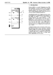
Attention ! The A-113 module requires an additional
+5V power supply with 100mA (e.g. the separate +5V
power supply or the +5V low-cost adapter)
Module A-113 (Subharmonic Generator) is an additional sound source that derives four independend
so-called Subharmonics from an incoming pulse signal. The module represents the sound generation
core of the Mixtur-Trautonium introduced by Oskar
Sala (ref. chapter 6).
Subharmonic means in this context a sawtooth wave
whose frequency is derived from a master frequency.
The master frequency is divided by an integer 1...24 to
obtain the subharmonic. The subharmonics are available as 4 single outputs as well as mix output with
adjustable level for each subharmonic.
The integer divisor for each subharmonic is set with
up/down buttons. The current divisors are displayed
with four 2-digit LED displays.
The combination of 4 divisors is called mixture. 4
mixtures form a preset. 50 presets can be stored and
called up within the module.
Two gate inputs are available to switch between the
4 mixtures within one preset (controlled by any gate
signals, e.g. from foot controllers).
1
A-113 Subharmonic Generator
System A - 100
2. Basic principles
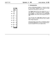
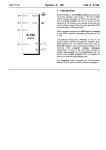
The Subharmonic Generator A-113 contains four times the following elements (see fig. 1)
• digital frequency divider (rectangle outputs) with
2-digit display and up/down buttons for divisor adjustment
• rectangle/sawtooth converter (with single output)
• attenuator controlling the amount (i.e. the amplitude) of the subharmonic in the mix output
The incoming signal (preferably the rectangle ouput of
a VCO) is fed into the four frequency dividers. The
frequencies of the rectangle signals generated by the
frequency dividers are determined by the current divisors (1...24).
The rectangle outputs are converted to sawtooth waveforms by means of the rectangle/sawtooth converters.
Fig. 1: Basic layout of the A-113
2
doepfer
System A - 100
doepfer
Subharmonics
The subharmonics result from integer division of
the frequency of the input signal.
The table in fig. 2 shows the frequencies and corresponding tone pitches of the resulting subharmonics
5
derived from an input signal with the tone pitch C (i.e.
523,2 Hz).
Divisor Freq. [Hz]
Subharmonic Generator A-113
It becomes apparent that the subharmonics are equivalent to the tones of the minor chord scale.
By way of contrast the harmonics are equivalent to
the tones of the major chord scale. Harmonics are
integer multiples of the basic frequency (see fig. 3).
The undertone series (i.e. subharmonics) are the
mirror image of the overtone series (i.e. harmonics).
Factor Freq. [Hz]
Note
Note
1
523,2
C5
1
65,4
C2
2
261,6
C4
2
130,8
C3
3
174,6
F3
3
196,0
G3
4
130,8
C3
4
261,6
C4
5
103,8
As2
5
329,6
E4
6
87,3
F2
6
392,0
G4
7
73,4
D2
7
466,1
B4
8
65,4
C2
8
523,2
C5
Fig. 2: Subharmonics of a signal with tone pitch C
5
Fig. 3:
Harmonics of a signal with tone pitch C
2
3
A-113 Subharmonic Generator
System A - 100
H The term "subharmonic" is not quite correct as
the A-113 outputs are sawtooth waveforms in
contrast to the sine waves used in the harmonics theory. A sawtooth wave has a marked
harmonic spectrum with odd and even overtones in contrast to the sine wave which is a
“pure” wave without overtones. For details concerning harmonic contents of different waveforms please refer to the A-110 or A-111
manual
(VCO´s).
We wanted to use the same terms as Oscar
Sala in his Mixtur Trautonium and this is why
we call the outputs of the A-113 subharmonics
though they are sawtooth outputs.
Mixture
The combination of four subharmonics is called a
mixture. Four different mixtures ("00", "01", "10" und
"11") are available but only one mixture is active at a
time. The original Mixtur-Trautonium had only three
mixtures available but due to the binary structure of the
A-113 we introduced 4 mixtures.
The active mixture is selected by the current state of
the two gate control inputs. In the original MixturTrautonium 2 foot switches mounted left and right of
4
doepfer
the volume foot controller are used to switch between
the 3 mixtures.
Preset
A preset consists of 4 mixtures with 4 divisors each
(see fig. 4). 50 presets can be stored and called up
within the A-113 module. The original MixturTrautonium had no presets available. Each mixture
had to be changed manually.
T1
T1
T1
T1
divisor
T2
T2
T2
T2
(display)
T3
T3
T3
T3
T4
T4
T4
T4
mixture
"00" "01" "10" "11"
Fig. 4: Structure of a preset
System A - 100
doepfer
Controls:
2. Overview
➃
➂
➁
➀
A-113
1 Display :
2 Up :
SHG
Subharmonic Generator
8.8.
8.8.
8.8.
8.8.
Subharmonic Generator A-113
Divisor
Level
Single
Out
0
10
Single
Out
Level
0
10
Single
Out
Level
Store
0
Single
Out
4
0
In / Outputs:
➌
" Foot Ctr. 1 :
10
Level
Preset
➋
Foot Ctr.
In 2
3
Divisor
5 Preset :
6 Store :
Foot Ctr.
In 1
2
Divisor
➊
In
1
Divisor
➍
3 Down :
4 Level :
10
! In :
§ Foot Ctr. 2 :
Mix Out
➎
% Mix Out :
$ Single Out :
displays the current divisor
button to increase the divisor
data
same to decrease
output level control (mix output)
preset selection button
preset store button
common audio input
(rectangle input)
gate input 1 to switch between the mixtures
gate input 2 to switch between the mixtures
audio mix output
audio single output
➅
➄
5
A-113 Subharmonic Generator
System A - 100
3. Controls
1 Display
This is the 2-digit LED display that shows the current
value of the divisor.
In addition the decimal points of the displays are
used to display the current mixture (see fig. 5):
• no decimal point is on: mixture "00"
doepfer
1
1
1
1
2
2
2
2
3
3
3
3
4
4
4
4
Fig. 5:
Display of mixtures by means of decimal
points (from left to right: "00", "01", "10", "11")
• both decimal points are on: mixture "11"
H
Before you adjust the divisors be sure that
you have selected the right mixture!
The mixture selected depends upon the states of the
two gate inputs $ und % (see chapter 4).
The Up/Down buttons of frequency divider 4 are
used for preset selection instead of divisor adjstment
if the preset button 5 is operated simultaneously.
• right decimal points are on: mixture "01"
• left decimal points are on: mixture "10"
2 Up
•
3 Down
The Up button 2 resp. the Down button 3 are used to
adjust the divisor (range 01 to 24 ) for the corresponding frequency divider.
6
4 Level
The attenuators 4 control the amount of the
respective subharmonic present at the mix output
%.
System A - 100
doepfer
5 Preset
While button 5 is operated one reaches the preset
mode (see chapter 2 concerning the term preset). In
this state the displays of the third and fourth frequency
divider show “Pr" resp. the number of the preset
currently selected (e.g. “45", see fig. 6a):
1
1
2
2
(a)
3
4
Fig. 6:
(b)
3
4
(a): display of the current preset
(b): store preset with new preset number
To select a new preset the up/down buttons 2 and 3
of the fourth frequency divider are used while the
preset button 5 is operated until the desired preset
number appears in the fourth display.
As soon as the preset button 5 is released the module
returns to the normal mode. The displays show the
divisors of the new preset and the divisors can be
adjusted with the corresponding up/dow buttons.
Subharmonic Generator A-113
6 Store
The store button 6 is used to store presets. The
following steps are required to store a new preset:
D Operate the preset button 5 and keep this button
pressed down (see fig. 6a).
D The up/down buttons 2 and 3 are used to select
the preset number in which the current preset will
be stored (preset button 5 remains operated).
D Pressing the store button 6 (preset button 5 still
remains operated) causes the storage of the current preset into the preset number selected. In the
upper displays appears "St" and "or" as confirmation of the storage process (see fig. 6b).
H
Pay attention not to select a preset number that already contains preset data you
may need in the future. Any former preset
data in the selected preset number are
deleted!
As soon as both buttons preset 5 and store 6 are
released the module returns to the normal mode. The
displays show the divisors and the divisors can be
adjusted with the corresponding up/dow buttons.
7
A-113 Subharmonic Generator
System A - 100
4. In / Outputs
The mixture is displayed with the decimal points (see
chapter 3, fig. 5).
! In
Socket ! is the subharmonic generator’s audio input.
Connect up the signal you wish to use as master
frequency signal (normally the rectangle output of a
VCO).
" Foot Ctr. In 1
•
§ Foot Ctr. In 2
The gate inputs " and § are used to select the
mixture. Any gate type signals may be used (e.g. Foot
Controller, Sequencer gate outputs, MIDI interface)
(see fig. 7).
Foot Ctr.
In 1
Foot Ctr.
In 2
Mixture
0
0
"00"
0
1
"01"
1
0
"10"
1
1
"11"
Fig.
8
7:
doepfer
Display example
Selecting mixtures with gate signals
(0: gate = low or no gate signal applied,
1: gate = high)
$ Single Out
Sockets " outputs the single subharmonic of the
respective frequency divider. The attenuators 4 do not
affect the level at these sockets.
% Mix Out
At output § the mix of the 4 subharmonics adjusted
with the 4 attenuators 4 is available.
doepfer
System A - 100
5. User Examples
Simulation of a Mixtur-Trautonium
The Trautonium is an electronic musical instrument
invented by Friedrich Trautwein in the thirties in Berlin,
Germany, with enhancements made by Oskar Sala in
the fifties which led to the well known MixturTrautonium. The Trautonium can be divided into two
logical sub-units: the control unit and the sound generation unit.
A detailed description of the Mixtur-Trautonium and
the realization with the A-100 modular system can be
found on our web site www.doepfer.com.
The replica of the Trautonium sound generation with
the A-100 presents itself as the A-113 contains all the
basic sound source elements of the Trautonium. The
Trautonium Format Filter A-104 completes the sound
generation as it is a copy of the lowpass/bandpass
arrangement of the Mixtur Trautonium. Only a few
A-100 standard modules (VCO, VCA, LFO, ADSR)
have to be added to obtain the typical Trautonium
sound.
Subharmonic Generator A-113
A-113 as a complex sound source
A-113 in combination with a VCO makes available a
very complex and powerful sound source for a lot of
sound experiments. The four subharmonics generated
by the A-113 contain strong harmonic spectra with
even and odd harmonics. They represent ideal basic
sound sources to be modified with separate sound
processing modules.
Fig. 9 shows an example. "XYZ" represents any sound
processing combination of modules: e.g. VCF, VCA,
Phaser, Distortion, Ring Modulator, Vocoder, Frequency Shifter, Spring Reverb and so on with controlling modules like ADSR, LFO, Random, S&H, Theremin, Light-controlled CV, Joy Stick, MIDI interface and
so on. The controlling modules may be triggered or
synchronized (e.g. with a keyboard or sequencer controlled gate) or free running.
Fig. 8 shows the schematic construction of the Trautonium sound generation using A-100 modules.
9
A-113 Subharmonic Generator
System A - 100
Fig. 8 :
10
doepfer
Schematic construction of the MixturTrautonium sound generation
(part 2 see next page)
doepfer
System A - 100
Subharmonic Generator A-113
11
A-113 Subharmonic Generator
A -113
VC- Mixer
XYZ
Audio
In 1
V CO
MOD
ext . CV
In 1
A udio
Out
VCA
VCA
MOD
4
Trig
Fig. 9: A-113 as a complex sound source
12
doepfer
A -135
SHG
Single
Out 1
System A - 100
Trig
MOD
Tr ig
Mix
doepfer
System A - 100
Subharmonic Generator A-113
7. Patch-Sheet
The following diagrams of the module can help you
recall your own Patches. They’re designed so that a
complete 19” rack of modules will fit onto an A4 sheet
of paper.
Photocopy this page, and cut out the pictures of this
and your other modules. You can then stick them
onto another piece of paper, and create a diagram of
your own system.
Make multiple copies of your composite diagram, and
use them for remembering good patches and set-ups.
P
• Draw in patchleads with colored pens.
• Draw or write control settings in the little
white circles.
A-113
SHG
Subharmonic Generator
Divisor
8.8.
8.8.
8.8.
8.8.
Divisor
Level
Single
Out
In
1
0
Divisor
10
Level
Single
Out
Foot Ctr.
In 1
Single
Out
Foot Ctr.
In 2
2
0
Divisor
10
Level
Store
3
0
Divisor
10
Single
Out
Level
Preset
Mix Out
4
0
10
13
A-113 Subharmonic Generator
14
System A - 100
doepfer