1
CONFIGURATION GUIDE
,%!$
&2
PP +J
55
6S
3):%
(2
[
(&*
3$'6
,%!$
#(!2'%
3):%
!.!,9:%
3(/#+
%.%2'9
3%,%#4
!,!23530%.$
(&*
2%#/2$%2
$%&)"
-/.)4/2
&2
/&&
0!#%2
3DUDP
:DYH
,'
35--!29
#(!2'%2/.
$ODUPV
/HDG
0!#%2
/54054
M!
0!#%2
2!4%
PPM
#/$%
-!2+%2
2%,%!3%
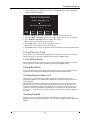
9650-0201-01 Rev YB
January 2007
An issue or revision date for this manual is shown on the front cover.
If more than three years have elapsed since this date, contact ZOLL Medical Corporation to determine if additional
product information updates are available.
ZOLL, M Series, and stat•padz are registered trademarks of ZOLL Medical Corporation. PowerCharger, PD, Connect
Alarm, ZOLL Data Control Software, Smart Alarms, Speed Pack, Preconnect and “Advancing Resuscitation. Today.”
are trademarks of ZOLL Medical Corporation.
All other trademarks and registered trademarks are property of their respective owners.
Copyright 2007 by ZOLL Medical Corporation. All rights reserved.
Table of Contents
INTRODUCTION .............................................................................................................................1
CONFIGURING THE UNIT ............................................................................................................1
SELECT LANGUAGE ....................................................................................................................2
MAIN CONFIGURATION MENU ...................................................................................................3
PRINT CONFIG .............................................................................................................................3
RESTORE DEFAULTS ...................................................................................................................3
READ FROM CARD .....................................................................................................................4
CHANGE CONFIG ........................................................................................................................4
CONFIGURATION SETTINGS ......................................................................................................5
NOTCH FILTER ............................................................................................................................5
ALLOW CARD ERASE .................................................................................................................5
DISPLAY ELAPSED TIME .............................................................................................................5
VOICE MARKERS ENABLED ........................................................................................................5
SET REPORT RESTART DELAYS ..................................................................................................6
PRINT 12 LEAD 4X3 ....................................................................................................................6
AUTO SELF-TEST TIMEOUT PERIOD ...........................................................................................6
ASYNC SOFTKEY IN PACE MODE ...............................................................................................6
CODE MARKERS .........................................................................................................................6
DEVICE IDENTIFIER ....................................................................................................................8
MANUAL MODE PASSCODE (ADVANCED AED MODELS) ..........................................................8
CONFIGURATION MODE PASSCODE ............................................................................................9
ENERGY LEVEL: SHOCK 1, 2, 3 ..................................................................................................9
AUTO ANALYZE ..........................................................................................................................9
STACKED SHOCKS ......................................................................................................................9
DISPLAY DO CPR MESSAGE ....................................................................................................10
CPR MESSAGE AFTER SHOCK .................................................................................................10
CPR MESSAGE AFTER NO SHOCK ADVISED ............................................................................10
CHECK PULSE ...........................................................................................................................10
RESTART ANALYSIS AFTER CPR .............................................................................................11
DURATION OF CPR INTERVAL .................................................................................................11
“CHECK PATIENT” PROMPT .................................................................................................11
DISPLAY ECG IN SEMI-AUTO MODE .......................................................................................11
STORE TO CARD IN AUTO MONITOR MODE (AED MODELS) ...................................................11
AUTO CHARGE IN ADVISORY MODE ........................................................................................11
ENABLE VOICE IN ADVISORY MODE .......................................................................................11
ECG WAVEFORM TO CARD IN ADVISORY MODE ....................................................................11
AUDIO DATA RECORDING TO CARD IN ADVISORY MODE .......................................................11
DISPLAY HEART RATE IN SEMI-AUTO MODE ..........................................................................12
DISPLAY LEAD ON POWER-UP .................................................................................................12
FREQUENCY RESPONSE ............................................................................................................12
ENABLE 12-LEAD IN SEMI-AUTO MODE (AED WITH 12-LEAD) .............................................12
QRS VOLUME ON POWER-UP ..................................................................................................12
PACE RATE SETTING ON POWER-UP ........................................................................................12
ENABLE PACER DETECTION .....................................................................................................12
GAIN ON POWER-UP ................................................................................................................12
RETAIN SYNC AFTER DEFIB ....................................................................................................12
AUTO GENERATE STRIPS ..........................................................................................................12
PRINT 3 LEADS WHEN LEADS SEL ...........................................................................................13
i
M SERIES CONFIGURATION GUIDE
REPORT MEMORY CARD ERRORS ............................................................................................13
AUTO ANALYZE ON POWER UP (AED SEMI-AUTOMATIC MODE) ..........................................13
EXTRA CPR INTERVAL BEFORE 1ST ANALYSIS .......................................................................13
DURATION OF EXTRA CPR INTERVAL .....................................................................................13
AUTO TRANSMIT AFTER 12 LEAD ............................................................................................13
FAX/COMMUNICATION PHONE NUMBERS ................................................................................13
12 LEAD ANALYSIS ..................................................................................................................15
12 LEAD PRINTOUT ..................................................................................................................15
PRINT 12 LEAD MEASUREMENTS .............................................................................................15
12 LEAD FAX FORMAT .............................................................................................................16
PRINT 2 COPIES 12 LEAD .........................................................................................................16
SET LEAD GROUPS ...................................................................................................................16
12 LEAD FREQ RESPONSE ........................................................................................................16
LEAD GROUP DEFAULT ............................................................................................................17
PRINT 12 LEAD INTERPRETATION ............................................................................................17
DEFIB DEFAULT TO PADS .........................................................................................................17
CELL PHONE TYPE ....................................................................................................................17
ETCO2 OPTIONS .......................................................................................................................17
ENABLE LEADS OFF .................................................................................................................17
NIBP UNITS ..............................................................................................................................18
NIBP AUTO INTERVAL DEFAULT .............................................................................................18
TRIGGER NIBP MEAS ON BP ALARM ......................................................................................18
TRIGGER NIBP MEAS ON HR ALARM .....................................................................................18
NIBP FIRST INFLATE PRESSURE DEFAULT ..............................................................................18
BASIC AUTO ENERGY ESCALATION .........................................................................................18
MUSE SITE AND LOCATION .....................................................................................................18
12 LEAD SECS PER LEAD .........................................................................................................19
12 LEAD PRINT SPEED ..............................................................................................................19
UPLOAD BAUD RATE ................................................................................................................19
TRENDING REPORT ZOOM LEVEL ............................................................................................19
TRENDING ENABLED ................................................................................................................19
AED DEFIB READY HOLD TIME (AED SEMI-AUTOMATIC MODE) .........................................20
BATTERY TYPE USED ...............................................................................................................20
ALARM LIMITS AT POWER UP ..................................................................................................21
ALARMS ACTIVE AT POWER UP ...............................................................................................21
LOW BATTERY TONE ................................................................................................................21
CLOCK SYNCHRONIZATION ......................................................................................................21
DAYLIGHT SAVINGS .................................................................................................................22
CARD CAPACITY MESSAGE ENABLED ......................................................................................22
ERASE CARD PROMPT AT PWR OFF .........................................................................................22
REMOVE CARD PROMPT AT PWR OFF ......................................................................................23
SYNC DEFIB EXCLUDED ...........................................................................................................23
PTCA SETTINGS .......................................................................................................................23
ENABLE DATA RELAY ..............................................................................................................23
CONFIGURATION OPTION TABLES ........................................................................................25
GENERAL ..................................................................................................................................25
ADVISORY AND SEMI-AUTOMATIC MODES ..............................................................................27
MANUAL MODE ........................................................................................................................28
ETCO2 OPTION ........................................................................................................................29
NIBP OPTION ...........................................................................................................................29
PTCA SETTINGS OPTION ..........................................................................................................29
ii
Introduction
The M Series is designed with several user selectable features that allow operators to configure
the device according to their protocols and local requirements. This manual describes the
configuration options and how to change them. This manual also lists the configurable features,
options and default settings. Some features are available to manual mode operators only.
The default settings shown below are for North American units only. To print the current
configuration of your unit, while the unit is in the configuration mode, press the Print Config
softkey.
CAUTION
The following features are not currently implement on the M Series products: Voice Markers
and Auto Self-Test. Refer to the “Configuration Option Tables” section for specific features that
are not currently implemented.
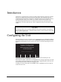
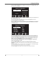
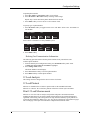
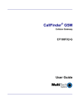
Configuring the Unit
After the unit has been off for 10 seconds or more, simultaneously press and hold the rightmost
and leftmost softkeys. Turn the selector switch to MONITOR or ON while holding the buttons
depressed for approximately four (4) seconds. After four (4) seconds the following screen will
appear.
6\VWHP&RQILJXUDWLRQ
(QWHU&RQILJXUDWLRQ3DVVFRGH
RU3RZHU2IIWR([LW
""""""""
'HOHWH
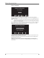
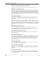
Users entering System Configuration for the first time must enter the default pass code
(00000000) for System Configuration to continue.
Press the 0 (zero) softkey. This will move the highlight to the next digit. Repeatedly press the 0
(zero) softkey until all eight digits have been entered. The Configuration Pass code screen will
then automatically advance to the Select Language menu.
To change one of the entered digits use the Delete softkey to highlight the incorrect digit and
reenter the correct code.
1
M SERIES CONFIGURATION GUIDE
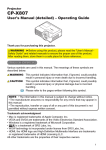
Select Language
6\VWHP&RQILJXUDWLRQ
6HOHFW/DQJXDJH
(1*/,6+
)5$1&$,6
3UHY
9DOXH
1H[W
9DOXH
(QWHU
([LW
&RQILJ
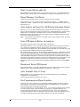
The first configurable option displayed after entering the correct pass code, is the Select
Language menu. Press the Prev Value and Next Value softkeys to move the highlight from one
language to the other.
Note: Some M Series units include software that allows the device to operate in either of two
languages. If the languages displayed do not meet your needs contact ZOLL Technical
Service for a language upgrade.
Press the Enter softkey to select the highlighted language and move to the Main Configuration
menu. All subsequent configuration menus will be in the selected language. Press the Exit
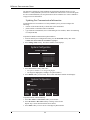
Config softkey to display the following three choices:
6\VWHP&RQILJXUDWLRQ
6DYH&KDQJHVDQG([LW
'LVFDUG&KDQJHVDQG([LW
5HWXUQWR0DLQ0HQX
3UHY
,WHP
1H[W
,WHP
(QWHU
Press the Prev Item or Next Item softkey to scroll the highlight to the desired function. Press
the Enter softkey to activate the selected function.
If the Return to Main Menu is selected, the unit will then display the Select Language menu
described in the previous section.
Caution: Print out the summary report before changing languages. If a summary report
containing Code Marker events is printed after changing languages, the Code Marker events
will not match.
2
Configuring the Unit
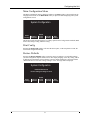
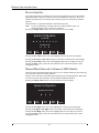
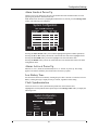
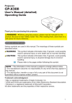
Main Configuration Menu
The Main Configuration menu is displayed whenever the Enter softkey is depressed from the
Language Select menu or the Main Menu softkey is depressed while displaying other system
configuration screens.
6\VWHP&RQILJXUDWLRQ
3ULQW
&RQILJ
5HVWRUH
'HIDXOWV
5HDG
)URP
&DUG
&KDQJH
&RQILJ
([LW
&RQILJ
This menu provides the following five (5) softkey options: Print Config, Restore Defaults, Read
From Card, Change Config, and Exit Config.
Print Config
Pressing the Print Config softkey will cause the unit to print, via the strip chart recorder, the
current unit configuration settings.
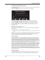
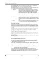
Restore Defaults
Pressing the Restore Defaults softkey causes the unit to reconfigure it to its default settings.
(See the Configuration Options Table section). The display language is the only setting, which
if different from the default, will not change. Once the default settings have been restored the
“Defaults Restored” and “Press Change Config to View” messages will be displayed.
6\VWHP&RQILJXUDWLRQ
'HIDXOWV5HVWRUHG
3UHVV&KDQJH&RQILJWR9LHZ
3ULQW
&RQILJ
5HVWRUH
'HIDXOWV
5HDG
)URP
&DUG
&KDQJH
&RQILJ
3
([LW
&RQILJ
M SERIES CONFIGURATION GUIDE
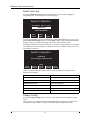
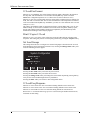
Read From Card
Pressing the Read From Card softkey prompts the user to choose either a language or
configuration card. The following screen will be displayed.
6\VWHP&RQILJXUDWLRQ
5HDG:KLFK7\SHRI&DUG"
/$1*8$*(
&21),*85$7,21
3UHY
9DOXH
(QWHU
1H[W
9DOXH
To move the highlighted area from LANGUAGE to CONFIGURATION and vice versa, press
the Prev Item and Next Item softkeys. Press the Enter softkey to begin reading and storing the
language settings or configuration settings from the user installed memory card.
If a language card has been read and loaded, the “Card Read” message displays. If a configuration card has been read and loaded, the “Card Read” and “Press Change Config to View” messages display (see below):
6\VWHP&RQILJXUDWLRQ
&DUG5HDG
3UHVV&KDQJH&RQILJWR9LHZ
3ULQW
&RQILJ
5HVWRUH
'HIDXOWV
5HDG
)URP
&DUG
&KDQJH
&RQILJ
([LW
&RQILJ
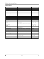
If there is an error reading the memory card, one of the following error messages will be
displayed on the monitor.
EROR MESSAGE
DEFINITION
CARD READ FAILED
No response from card reader
BAD CARD
Cannot read from card
WRONG CARD TYPE
Card is the wrong type
CONFIG DATA NOT COMPATIBLE
Internal software is unable to read card data
NO CARD INSERTED
Card is not installed in PCMCIA slot
CARD EMPTY
No data on card
Change Config
Pressing the Change Config softkey causes the unit to display the first configuration option
menu.
There are three user configurable features contained within each option menu. (Refer to the
“Configuration Option Tables” section for all available options and default settings).
4
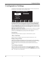
Configuration Settings
Configuration Settings
A description of each configurable feature is displayed in the left column of the option menu
and that feature’s current setting is shown in the right column.
6\VWHP&RQILJXUDWLRQ
127&+
),/7(5
+]
$//2:
&$5'(5$6(
',63/$<
(/$36('7,0(
&KDQJH
9DOXH
3UHY
,WHP
1H[W
,WHP
0DLQ
0HQX
([LW
&RQILJ
Pressing the Change Value softkey allows you to sequence through the available settings for
the highlighted feature. When the desired setting is displayed, pressing the Next Item softkey
will enter the selection and move the highlight to the next feature. Pressing the Prev Item
softkey will enter the selected setting and move the highlight to the previously selected feature.
Pressing the Main Menu softkey will cause the unit to return to the Main Configuration menu
(See Main Configuration Menu Section). Pressing the Exit Config softkey will cause the unit to
display the “Save Changes and Exit” screen.
NEXT MENU is displayed on the screen when other option menus are available. Press the Next
Item softkey until the new menu is displayed.
PREV MENU is displayed on the screen when other previously displayed option menus are
available. Press the Prev Item softkey until the previous menu is displayed.
Notch Filter
Sets the ECG Notch Filter frequency for proper AC mains interference rejection.
Allow Card Erase
Allows the user to erase PCMCIA data cards on the M Series unit when set to “Yes”.
Display Elapsed Time
Allows the user to display the elapsed time since the unit was turned on, when enabled. The
elapsed time will continue to be counted for up to 10 seconds after power down. This will give
the operator adequate time to change the battery without resetting the elapsed timer.
Elapsed time will be reset to zero (0:00) whenever the unit has been off for more than 10
seconds.
Voice Markers Enabled
When voice markers are enabled, the unit will record five seconds of audio data in internal
memory immediately following each depression of the CODE MARKER button. This audio
recording along with a time stamp can be played back when the SUMMARY button is pressed.
Note: This option is not yet implemented.
5
M SERIES CONFIGURATION GUIDE
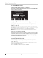
Set Report Restart Delays
Allows review of, or changes to the length of time the device must be turned off before it erases
all data stored in either summary report memory or trend memory.
With Set Report Restart Delays highlighted and Set/Review selected, press the Change Value
softkey. The following screen displays:
6\VWHP&RQILJXUDWLRQ
5(67$57'(/$<7,0(6
6800$5<5(3257
5(67$57'(/$<
0,1
75(1'5(3257
5(67$57'(/$<
0,1
&KDQJH
9DOXH
3UHY
,WHP
1H[W
,WHP
(QWHU
Pressing the Change Value softkey will scroll the highlight through the available delay times.
Pressing the Prev Item and Next Item softkeys will scroll the highlight to the next or previous
restart delay feature.
Pressing the Enter softkey will cause the unit to return to the main configuration menu.
Print 12 Lead 4x3
Determines how many copies of a 12-lead 4x3 report will print after pressing and holding the
RECORDER button for three seconds. When set to “1 Copy” or “2 Copies” one or two copies
of the 12-lead 4x3 report will print. When set to “None”, pressing and holding the
RECORDER button will cause a one or three lead DIAG BANDWIDTH ECG strip to be
printed.
Auto Self-Test Timeout Period
Allows the user to set the time between tests or disable the automatic tests. The unit is capable
of automatically running a self-test at seven to thirty day intervals. If the unit is off, plugged in,
and the test connector is attached to the Multi-Function cable, the unit will test the battery
status, charge and discharge the defibrillator, measure the amplitude and timing of the pacing
waveform, and measure the impedance of the test port.
Note: This option is not yet implemented.
Async Softkey in Pace Mode
Sets the unit to display the Async Pacing On/Off softkey when the unit is in pace mode.
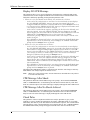
Code Markers
Allows review of or changes to the preconfigured list of Code Markers available for use in
PACER, MONITOR, and DEFIB modes.
Note: MONITOR Code Markers are not used in AED Models.
6
Configuration Settings
With Code Markers highlighted and Config/Review selected, press the Change Value softkey.
The following screen displays:
6\VWHP&RQILJXUDWLRQ
'(),%
&KDQJH5HYLHZ
&2'(0$5.(56
&KDQJH5HYLHZ
021,725
&KDQJH
9DOXH
3UHY
,WHP
&KDQJH5HYLHZ
1H[W
,WHP
(QWHU
5HWXUQ
Pressing the Change Value softkey will change the highlighted setting from Change/Review to
Set to Defaults and vice versa.
Pressing the Prev Item and Next Item softkeys will scroll the highlight to the next or
previously highlighted code markers feature.
Pressing the Enter softkey when the Change/Review option is highlighted for one of the code
markers features causes the following screen to be displayed (this example shows the Defib
Code Markers screen).
6\VWHP&RQILJXUDWLRQ
'HILE0DUNHUV0DUNHU/LVW
,WHP&35
&35
,WHP,QWXEDWH
(3,
,WHP(3,
$WURS
,WHP/,'2
'23$
,WHP%5(7
,VRSURW
,WHP%EORFN
%LFDUE
,WHP$0,2
$VSLULQ
,WHP0DJ6XOI
2[\JHQ
&KDQJH
9DOXH
3UHY
,WHP
1H[W
,WHP
'HOHWHWR
(QG
5HWXUQ
Pressing the Change Value softkey will highlight the first clinical action in the Marker List
column and change the softkeys so that a new clinical action may be entered (shown below).
Pressing the Prev Marker and Next Marker softkeys scroll the highlight through the entire
Marker List. Press the Enter Marker softkey to replace the highlighted item in the Defib
markers column with the highlighted clinical action in the Marker List.
Pressing the Prev Item or Next Item softkeys will scroll the highlight to a different item
number in the Defib Markers column.
Pressing the Delete to End softkey will delete all configured Defib markers from the
highlighted item number to the end of the list. The user can then enter new clinical actions for
each item.
Pressing the Return softkey will return the unit to the Change/Review Code Markers display
where the user can choose Defib, Monitor or Pace Code Markers.
Pressing the Return softkey again causes the unit to return to the previous menu.
7
M SERIES CONFIGURATION GUIDE
Device Identifier
Sets an eleven-digit device identifier code. This code is divided into two sub codes (Site ID,
eight alphanumeric characters, and Device ID, three alphanumeric characters). The device
identifier is printed on the 12-lead strip chart, summary report, fax and Catalyst™ MUSE®
printouts.
Catalyst MUSE is a registered trademark of GE Medical Systems.
Note: If you are transmitting 12-lead ECG data to a Catalyst MUSE system, it is
recommended that you set up the device identifier.
Pressing the Change Value softkey causes the following screen to display:
6\VWHP&RQILJXUDWLRQ
6HW6LWH,'
6HW'HYLFH,'
3UHY
/HWWHU
,QF
/HWWHU
1H[W
/HWWHU
'HF
/HWWHU
(QWHU
Pressing the Prev Letter softkey moves the highlight left to the previous entered digit.
Pressing the Inc Letter or Dec Letter softkeys increments or decrements the selected digit.
Pressing the Next Letter softkey moves the highlight right to the next digit to be entered.
Pressing the Enter softkey selects the values that have been entered and returns to main
configuration menu.
Manual Mode Passcode (Advanced AED Models)
Allows the three-digit Manual Mode Passcode to be set or changed. Each digit entered can only
be set between 0 (zero) and 3 (three) inclusive.
Entering “000” as the pass code disables password protection of the Manual Mode. When “000”
is selected, no password is required to enter the Manual Defibrillation Mode.
Pressing the Change Value softkey causes the following screen to display:
6\VWHP&RQILJXUDWLRQ
6HW0DQXDO3DVVFRGH
3UHY
'LJLW
,QF
'LJLW
1H[W
'LJLW
'HF
'LJLW
(QWHU
Pressing the Prev Digit softkey moves the highlight left to the previous entered digit.
Pressing the Inc Digit or Dec Digit softkeys increments or decrements the selected digit.
Pressing the Next Digit softkey moves the highlight right to the next digit to be entered.
Pressing the Enter softkey selects the values that have been entered and returns to main
configuration menu.
8
Configuration Settings
Configuration Mode Passcode
Sets an eight digit Configuration Passcode. Each digit entered can only be set between 0 (zero)
and 3 (three) inclusive.
Pressing the Change Value softkey causes the following screen to display:
6\VWHP&RQILJXUDWLRQ
6HW&RQILJXUDWLRQ3DVVFRGH
3UHY
'LJLW
,QF
'LJLW
1H[W
'LJLW
'HF
'LJLW
(QWHU
Pressing the Prev Digit softkey moves the highlight left to the previous entered digit.
Pressing the Inc Digit or Dec Digit softkeys increments or decrements the selected digit.
Pressing the Next Digit softkey moves the highlight right to the next digit to be entered.
Pressing the Enter softkey selects the values that have been entered and returns to main
configuration menu.
Energy Level: Shock 1, 2, 3
Selects the energy levels used for the 1st, 2nd, and 3rd consecutive shocks that the defibrillator
delivers when:
In semi-automatic or advisory mode and using pads
• Ιn manual mode, using external paddles or pads, with Basic Auto Energy Escalation set
to “Yes”
•
Energy level 1 is the energy level the unit defaults to when the power is turned on with external
paddles or pads connected. For more information about the Basic Auto Energy Escalation
setting, see the “Basic Auto Energy Escalation” section of this manual.
Auto Analyze
This parameter allows you to specify whether the unit automatically repeats ECG rhythm
analyses after the delivery of shocks in the AED and Advisory modes and works in conjunction
with the Stacked Shocks parameter described next. Enabling this parameter also enables the
occurrence of post-shock CPR intervals. When set to No, which is the Manual mode default, the
unit does not perform foreground analysis automatically (with the exception of the first analysis
on power-up in Auto-Defib mode, if the unit is configured to analyze on power-up.)
When set to Yes, and the Stacked Shocks option is set to 3, the unit automatically analyzes the
patient’s ECG rhythm after the first and second shocks in each three-shock sequence. Following
delivery of the final shock, the unit stops automatic re-analysis and either displays a “CHECK
PULSE” prompt, or immediately begins a CPR interval, depending on additional parameter
settings. This function operates only when the Auto Charge in Advisory Mode is set to Yes.
When set to Semi-Auto Only, the unit functions as described above only when it is in AED
Semi-Auto mode. If the unit is changed to Manual mode From AED Semi-Auto mode, the unit
terminates any automatic analysis/re-analysis sequencing. If the Analyze button is pressed, the
unit analyzes only once.
Stacked Shocks
This parameter specifies the number of stacked shocks that must be administered prior to the
activation of a CPR interval and works in conjunction with the Auto Analyze parameter.
9
M SERIES CONFIGURATION GUIDE
Display DO CPR Message
This parameter allows you to specify whether the unit displays the configured CPR prompt
(described below) for the configured CPR time interval after each set of stacked shocks. The
unit behaves differently depending on this particular parameter value.
When set to No (the Manual mode default), the unit behaves as follows:
– At the end of any analysis with an outcome of no shock advised, the unit displays
the “NO SHOCK ADVISED” message. The unit then remains idle for the
configured CPR interval duration. After the CPR interval, if the Analyze button has
not been pressed, the “PRESS ANALYZE” message is displayed and remains until
a new analysis is started or the mode is changed.
– At the end of a stacked shock sequence (assuming the final shock is delivered) and
when the optional 10 second “CHECK PULSE” message disappears, the CPR
interval begins. The unit remains idle for the duration of the CPR interval. After the
CPR interval, if the Analyze button has not been pressed, the “PRESS
ANALYZE” prompt is displayed and remains until a new analysis is started or the
mode is changed.
– If the defibrillator disarms itself after it was charged (because the Defib Ready time
elapsed before a shock was delivered), the unit displays the “PRESS ANALYZE”
prompt until the Analyze button is pressed.
• When set to Yes, the unit behaves as follows:
– At the end of any analysis with an outcome of no shock advised, the unit displays
the “NO SHOCK ADVISED” message for 10 seconds, after which the message is
cleared and the configured CPR prompt is displayed for the duration of the CPR
interval. After the CPR interval, the “PRESS ANALYZE” prompt is displayed until
a new analysis is started or a mode change occurs. You can start a new analysis
during the CPR interval by pressing the Analyze button.
– At the end of a stacked shock sequence (assuming the final shock is delivered) and
when the optional 10 second “CHECK PULSE” message disappears, the CPR
interval begins. The configured CPR prompt is displayed for the duration of the
CPR interval. After the CPR interval, the CPR prompt is cleared and a new analysis
starts automatically.
– If the defibrillator disarms itself after it was charged (because the Defib Ready time
elapsed before a shock was delivered), the unit displays the “PRESS ANALYZE”
prompt until the Analyze button is pressed.
•
The Display DO CPR Message feature is operational only when the Auto Charge in Advisory
Mode and the Auto Analyze options are both set to Yes.
Note: When set to “Only in Semi-Auto,” the unit functions as described above only when it
is in AED semi-auto mode.
CPR Message After Shock
This parameter determines which CPR message/voice prompt, “IF NO PULSE, PERFORM
CPR,” or “PERFORM CPR,” is issued during the CPR interval after the delivery of the final
shock in a stacked sequence. The selected message is displayed through the entire CPR interval.
CPR Message After No Shock Advised
This parameter determines which CPR message/voice prompt, “IF NO PULSE, PERFORM
CPR,” or “PERFORM CPR,” is issued during the CPR interval after a No Shock Advised
analysis result. The selected message is displayed through the entire CPR interval.
Check Pulse
This parameter works in conjunction with the Auto Analyze parameter to give you the
capability to specify whether the unit displays the prompt “CHECK PULSE” for 10 seconds
immediately after delivery of the final shock in a stacked shock sequence, after each No Shock
Advised analysis result, or both. During this 10-second time interval, The “CHECK PATIENT”
and “PRESS ANALYZE” prompts are suppressed on M Series units in semi-auto mode,
10
Configuration Settings
although background analysis is active. After “CHECK PULSE” clears, the CPR interval
begins.
Restart Analysis After CPR
When this parameter is set to Yes (default), the analysis starts automatically after the CPR
interval following each shock. Analyses do not automatically restart after a CPR interval
following No Shock Advised results. When this parameter is set to No, the PRESS ANALYZE
message is displayed, but the analysis does not restart.
Duration of CPR Interval
This parameter allows you to specify the duration of the CPR interval (1, 1.5, 2, 2.5, 3, 3.5, or 4
minutes) as described in the Display DO CPR Message parameter.
“CHECK PATIENT” Prompt
Changes the display message and the voice prompt issued when a shockable rhythm has been
detected by background ECG analysis and Heart Rate Alarms are enabled, or the unit is
operating in Semi-Automatic mode.
Display ECG in Semi-Auto Mode
Sets the unit to display or not display the patient’s ECG trace on the monitor while in
semiautomatic mode.
Store to Card in Auto Monitor Mode (AED models)
Sets the unit to store patient’s ECG trace and voice data automatically to the PCMCIA card
when:
• ECG leads are attached to the patient
MFE pads are not connected
• M Series unit is on
•
If disabled, the M Series unit will not record any data to the PCMCIA card unless MFE pads are
connected to the patient.
Auto Charge in Advisory Mode
When enabled and a shockable rhythm is detected after pressing the ANALYZE button, the
unit will automatically charge the defibrillator to the pre-configured or user selected energy
setting.
Enable Voice In Advisory Mode
Enables or disables voice prompts when operating in Advisory or Manual operating modes. If
enabled, the voice prompts will sound at the appropriate time when in Advisory mode or
Manual mode.
ECG Waveform to Card in Advisory Mode
Sets the unit to record the ECG waveform continuously to the PCMCIA card while in advisory
mode.
Audio Data Recording to Card in Advisory Mode
Sets the unit to record audio data continuously to the PCMCIA card while in advisory mode.
11
M SERIES CONFIGURATION GUIDE
Display Heart Rate in Semi-Auto Mode
Sets the unit to display the patient heart rate on the monitor while in semiautomatic mode.
Display Lead on Power-Up
Allows the user to select any one of the following Leads to be displayed on power-up: Paddles/
Pads, I, II, or III. When the unit powers up in semi-automatic mode, the option is ignored. The
unit will power up in Lead II, and switch leads automatically between leads II and MFE for
Auto Monitor and Auto Defib modes, respectively. When the unit enters Manual Mode (Manual
Mode override sequence is completed), the lead switches to the setting specified in the “Display
Lead on Power Up” option.
Frequency Response
Selects the ECG filter bandwidth to be used during ECG monitoring. The frequency of the
device can be set to either help reduce noise, help with the diagnostic response, or set as a
default response.
Enable 12-Lead in Semi-Auto Mode (AED with 12-Lead)
If set to “Yes,” 12-lead analyses, transmissions and print-outs are available in semi-automatic
(AED) Auto Monitor mode (ECG leads on the patient with MFE Pads disconnected), depending
on other configuration option settings. If set to “No,” 12-lead functions are available in Manual
Mode only.
QRS Volume on Power-Up
Turns the default QRS beeper volume to midrange or off following power up of the unit.
If set to “Off in Semi-Auto Mode,” the QRS beeper volume turns off in semi-auto mode. If the
unit is changed to manual mode, the beeper volume sets to midrange.
Pace Rate Setting on Power-Up
Sets the default pace rate of the M Series unit on power-up, between 30 ppm and 102 ppm
(increments of 4 ppm).
Enable Pacer Detection
Allows you to specify whether the unit should detect pacemaker signals from a patient with an
implantable pacemaker and indicate those signals on the display. When set to Yes, a pacemaker
marker is displayed on the ECG trace whenever the unit detects implanted pacer stimuli.
You can override this setting during normal operations. This parameter simply indicates the
default setting at power-on.
Gain On Power-Up
Sets the default SIZE of the displayed ECG signal (AGC, 0.5 cm/mV, 1 cm/mV, 1.5 cm/mV,
and 2 cm/mV) when the device is powered-up.
Retain SYNC after Defib
Sets the unit to remain in SYNC mode after a synchronized cardioversion shock. The unit will
remain in SYNC mode until the SYNC button is pressed again or the unit is switched out of
Defib mode.
Auto Generate Strips
Sets the strip chart recorder to automatically begin printing after a defibrillator discharge or
whenever alarms are triggered while in manual mode. (Unit must be equipped with the optional
strip chart recorder feature.)
12
Configuration Settings
Print 3 Leads When Leads Sel
When enabled, the strip chart recorder will automatically print three (3) simultaneous leads of
the patient ECG when Leads are selected and a five (5) lead or 12-lead ECG cable is in use.
Report Memory Card Errors
Allows the user to disable memory card error messages and voice prompts.
If this option is set to “No”, the unit suppresses all error messages (i.e., “INSERT CARD”,
“REPLACE CARD”, “CARD FULL”, and “CARD LOW < n MINUTES”) related to the use of
the memory card.
Auto Analyze on Power Up (AED Semi-Automatic Mode)
When set to “Yes”, the unit will automatically begin an ECG rhythm analysis as soon as the
device is turned on and pads are properly connected. An “ANALYZING ECG” message will be
displayed for 5 seconds and a “STAND CLEAR” message is displayed and announced
indicating the start of the analysis. If the Auto Analyze option is enabled, the analysis will be
the first of a stacked shock sequence.
Note: The unit must be turned off for 10 seconds or more for the analysis to auto -start when
the device is turned on.
Extra CPR Interval Before 1st Analysis
This parameter pertains only to Auto Defib mode in AED units.
When this parameter is set to No (default), and the unit detects a pad connection upon poweron, it displays the “PRESS ANALYZE” prompt. If the unit is powered on with no pads
connected, the unit displays the “ATTACH PADS” prompt until pads are connected. Once pads
are connected, the “PRESS ANALYZE” prompt is displayed.
When this parameter is set to Yes, the unit displays alternating prompts “CHECK PULSE” and
“IF NO PULSE, PERFORM CPR” for the configured Extra CPR Interval at power-on. At the
end of the CPR period, if the unit does not detect a pads connection, it displays the prompt
“ATTACH PADS” until pads are connected. If a pads connection is detected, and the system is
configured to Auto Analyze On Power Up, the unit automatically starts an ECG analysis. If the
unit is not configured to Auto Analyze On Power Up, it displays the prompt “PRESS
ANALYZE.” You can start an ECG analysis during the CPR interval by pressing the Analyze
button.
Duration of Extra CPR Interval
This parameter allows you to specify the duration of the extra CPR interval (see previous entry).
It has no effect if “Extra CPR Interval Before 1st Analysis” is set to “No.”
Auto Transmit After 12 Lead
When enabled, the unit will automatically enter the transmission setup screen following
completion of a 12-lead analysis.
To fax using 2x6 format, this must be set to “Yes.”
Fax/Communication Phone Numbers
Allows the user to pre-configure up to 24 locations and phone numbers and delete obsolete
phone numbers. The M Series uses the phone numbers to transmit data to a fax machine or
Catalyst MUSE system following 12-lead analysis.
If you are transmitting to a Catalyst MUSE system, you can configure multiple phone numbers
to access the same system. This will enable you to quickly try alternate numbers if you
encounter difficulty transmitting to the Catalyst MUSE system. The system administrator
provides these numbers when you initially set up access to the system. See Appendix B of the
12-Lead ECG Monitoring insert (part number 9650-0215-01) for more information.
13
M SERIES CONFIGURATION GUIDE
You must also configure the Catalyst MUSE site and location identifiers before you can
transmit to a Catalyst MUSE system. See the “MUSE Site and Location” section of this guide.
It is also recommended that you set up the M Series device identifier. See “Device Identifier”
on page 8 for more information.
Updating Fax/Communication Information
To transmit data to a fax machine or a Catalyst MUSE system, you must configure the
following:
• location of the medical facility to which data will be transmitted
• phone number to which data will be transmitted
• type of data to be transmitted (“Fax” if transmitting to a fax machine; “Data” if transmitting
to Catalyst MUSE)
To update fax/MUSE communications phone numbers:
1. From the main System Configuration menu, press the Next Item softkey until “FAX/
COMMUNICATION PHONE NUMBERS” highlights.
2. Press Change Value softkey. The Phone Numbers menu displays:
6\VWHP&RQILJXUDWLRQ
3+21(180%(56
0HWUR+RVSLWDO
3UHY
1H[W
BBBBBBBBBBBBBBBBB
BBBBBBBBBBBBBBBBB
BBBBBBBBBBBBBBBBB
BBBBBBBBBBBBBBBBB
BBBBBBBBBBBBBBBBB
BBBBBBBBBBBBBBBBB
BBBBBBBBBBBBBBBBB
'HWDLOV
'HOHWH
5HWXUQ
3. Press Next or Prev softkey until either:
• The phone number to be changed highlights
• An empty line highlights (if adding a new phone number)
4. Press Details softkey to select field. The Location and Phone Number menu displays:
6\VWHP&RQILJXUDWLRQ
/RFDWLRQ
3KRQH1XPEHU
BBBBBBBBBBBBBBBBBBBBBBBBBBB
)D[RU'DWD")D[
3UHY
/HWWHU
,QF
/HWWHU
1H[W
/HWWHU
'HF
/HWWHU
(QWHU
To update location of medical facility:
1. Press Prev Letter or Next Letter softkey to select letter.
2. Press Inc Letter or Dec Letter softkey to change value of letter.
Repeat steps 1 and 2 until location has been entered.
3. Press Enter softkey to move cursor to first digit of phone number.
14
Configuration Settings
To update phone number:
1. Press Prev Letter or Next Letter softkey to select digit.
2. Press Inc Letter or Dec Letter softkey to change value of digit.
Repeat steps 1 and 2 until entire phone number has been entered.
3. Press Enter softkey to move cursor to “Fax or Data?” field.
To specify type of phone number:
1. Press Inc Letter softkey to toggle between “Fax” and “Data.” Select “Fax” to transmit to a
fax machine.
)D[RU'DWD")D[
3UHY
/HWWHU
,QF
/HWWHU
1H[W
/HWWHU
'HF
/HWWHU
(QWHU
Select “Data” to transmit to a Catalyst MUSE system.
)D[RU'DWD"'DWD
3UHY
/HWWHU
,QF
/HWWHU
1H[W
/HWWHU
'HF
/HWWHU
(QWHU
2. Press Enter softkey.
Deleting Fax/Communication Information
The following procedure deletes obsolete phone numbers from your M Series unit.
To delete phone numbers:
1. From the main System Configuration menu, press Next Item softkey until “FAX/
COMMUNICATION PHONE NUMBERS” highlights.
2. Press Change Value softkey.
The Phone Numbers menu displays.
3. Press Next or Prev softkey to scroll to phone number.
4. Press Delete softkey to delete phone number.
12 Lead Analysis
This setting cannot be changed in the current version of software.
12 Lead Printout
When set to “Standard” the 12-lead 4x3 printout will use the standard lead format.
When set to “Cabrera” the 12-lead 4x3 printout will use the Cabrera-style lead format.
Print 12 Lead Measurements
When set to “Yes” the 12SL™ Analysis will produce and print a measurements matrix
including measurements for each lead. Global measurements will be produced and printed
regardless of this setting. This setting affects the strip chart and summary report printouts as
well as the fax transmission. When set to “Yes” any faxed 12-lead report will contain two pages.
The second page of the report will contain the computed measurements matrix.
15
M SERIES CONFIGURATION GUIDE
12 Lead Fax Format
When set to “4x3 Standard” the 12-lead format on the fax output is identical to the format on
the strip chart, with the addition of a 10-second Lead II rhythm strip. (If the 12 LEAD
PRINTOUT configuration option is set to “Cabrera” the fax will be Cabrera as well.)
When set to “2x6” the 12-lead format on the fax output will be configured for two columns of 6
leads, each with 5 seconds of data. The fax will not contain the 12SL interpretative statements
or the 10-second Lead II rhythm strip. In addition, you must set “Auto Transmit After 12 Lead
Analysis” to “Yes.”
The setting “4x3 Median Compl” is supported in software versions higher than 17.00. If “4x3
Median Compl” is selected, the 12-lead ECG waveforms on the strip chart, summary report,
and fax will contain a single median complex beat computed by the GE Medical Systems
Information Technologies 12SL analysis program.
Print 2 Copies 12 Lead
When set to “Yes”, two copies of the 12-lead 4x3 report and 12SL analysis will print on the
strip chart. This setting only affects 12-lead reports generated by pressing the Acquire softkey.
Set Lead Groups
This setting allows the user to configure two custom lead groups as described in the 12-Lead
ECG Monitoring insert (part number 9650-0215-01). Pressing the Change Value softkey will
cause the following screen to appear:
6\VWHP&RQILJXUDWLRQ
&XVWRP*URXS
,,,,,D9)
&XVWRP*URXS
,,,,,9
3UHY
/HDG
1H[W
/HDG
&KDQJH
/HDG
(QWHU
Pressing the Prev Lead softkey will select the previous lead.
Pressing the Next Lead softkey will select the next lead.
Pressing the Change Lead softkey will change the selected lead. Repeatedly pressing this key
will cycle the selected lead through all twelve possibilities.
Pressing the Enter softkey will return to main configuration menu.
12 Lead Freq Response
When set to “0.05-150 Hz 4x3” the 12-Lead Filter Setting defaults to 0.05-150 Hz 4x3.
When set to “0.05-150 Hz Cont.” the 12-Lead Filter Setting defaults to 0.05-150 Hz Cont.
When set to “0.05-40 Hz 4x3” the 12-Lead Filter Setting defaults to 0.05-40 Hz 4x3.
Refer to the 12- Lead ECG Monitoring Operator’s Guide insert (part number 9650-0215-01)
for details on each setting.
16
Configuration Settings
Lead Group Default
When set to “Standard” the 12-Lead Group Setting defaults to Standard.
When set to “Custom Group 1” the 12-Lead Group Setting defaults to the setting defined under
Custom Group 1.
When set to “Custom Group 2” the 12-Lead Group Setting defaults to the setting defined under
Custom Group 2.
Refer to the 12- Lead ECG Monitoring Operator’s Guide insert (part number 9650-0215-01) for
details on each setting.
Print 12 Lead Interpretation
When set to “Yes” the 12SL interpretative statements will print following the acquisition of a
12-lead ECG. This setting affects the strip chart and summary report printouts as well as the fax
transmission.
Defib Default to Pads
When set to “Yes” switching the unit to DEFIB mode will set the active lead to Pads/Paddles
regardless of the configuration setting for “Display Lead on Power-Up.”
Cell Phone Type
This setting controls the active cellular phone profile for PCMCIA modem cards. It has no
effect on landline functionality. Pressing the Change Value softkey selects different phone
makes.
Select the phone make corresponding to your target cellular phone. For additional information
on cellular phone compatibility contact The Supply Net, Inc. at www.thesupplynet.com or
(800) 826-0279.
EtCO2 Options
Pressing Set/Review causes a submenu to display, which allows review of or changes to the
following capnography options:
• Default EtCO2 Units:
Sets EtCO2 units to mmHg, kPa, or %
• Displayed Zoom Level:
Sets the default scale setting for the displayed capnographic
waveform in the EtCO2 units selected above. Does not
affect the printed waveform or the waveform data stored on
the data card.
• Default EtCO2 Comp Setting: Sets the default compensation for CO2 to None, O2, N2O, or
O2+N2O.
• EtCO2 Average on Power Up Sets the time period over which the EtCO2 values are
averaged to: 1 breath, 10 seconds (default), or 20 seconds.
Enable Leads Off
When set to “Yes” and ECG leads do not have proper contact with the patient or the cable is not
properly attached to the M Series unit, the ECG LEADS OFF message displays and a dashed
line displays in place of the ECG waveform. Yes is the default setting.
When set to “No” and ECG leads do not have proper contact with the patient or the cable is not
properly attached to the M Series unit, the POOR LEAD CONTACT message and the ECG
waveform display.
Caution: Use care when interpreting ECG waveforms when the POOR LEAD CONTACT
message displays, because the ECG waveform may include a significant amount of artifact.
Whenever possible, reattach the leads before interpreting the waveform.
Note: When using 12 Lead or Pacer mode, the M Series unit functions as if this
configuration were set to “Yes.”
17
M SERIES CONFIGURATION GUIDE
NIBP Units
Sets the NIBP unit of measurement to mmHg or kPa.
NIBP Auto Interval Default
Sets the default for the amount of time between automatic measurements.
Trigger NIBP Meas on BP Alarm
When set to “Yes,” the M Series unit initiates a single additional blood pressure measurement
when any of the NIBP alarms trigger.
Trigger NIBP Meas on HR Alarm
When set to “Yes,” the M Series unit initiates a single blood pressure measurement when heart
rate/pulse rate alarm triggers.
NIBP First Inflate Pressure Default
Sets the default NIBP cuff inflation pressure (the pressure up to which the NIBP cuff inflates at
the beginning of each measurement).
Basic Auto Energy Escalation
When set to Yes, the unit automatically increments the defibrillation energy to the levels
specified in Energy Level: Shock 1, 2, 3 after each of the first two shocks and displays the
message “ENERGY INCREMENTED,” when both of the following are true:
• The defibrillator is in Manual mode
• The defibrillator has external paddles or pads attached
Manually changing the energy level outside the pre-programmed sequence and delivering a
shock disables this function until the unit is turned off for more than 10 seconds, then turned
back on.
This option increments the energy level regardless of Shock Advisory activation or status. It
does not work with internal handles.
For more information about the energy level settings, see the “Energy Level: Shock 1, 2, 3”
section of this manual.
MUSE Site and Location
Sets the Catalyst MUSE site and location identifiers needed to transmit 12-lead ECG data to a
Catalyst MUSE system. The medical facility’s Catalyst MUSE system administrator provides
these numbers when you initially set up access to the system. The Catalyst MUSE site has a
value between 01 and 32, and the location has a value between 001 and 600.
Note: You must also configure the Catalyst MUSE communications phone number. See the
“Fax/Communication Phone Numbers” section of this guide.
To set the Catalyst MUSE site and location:
18
Configuration Settings
1. From the main System Configuration menu, press Next Item softkey until “MUSE SITE
AND LOCATION” highlights.
6\VWHP&RQILJXUDWLRQ
6HW6LWH9DOLG5DQJH
6HW/RFDWLRQ9DOLG5DQJH
3UHY
'LJLW
,QF
'LJLW
1H[W
'LJLW
'HF
'LJLW
(QWHU
2. Press the Change Value softkey to display the MUSE Site and Location menu:
3. Press Prev Digit or Next Digit softkey to select digit and move to previous or next digit.
4. Press Inc Digit or Dec Digit softkey to change value of digit.
Repeat steps 3 and 4 until site has been entered.
5. Press Enter softkey to move cursor to first digit of location.
Repeat steps 3 and 4 until location has been entered.
6. Press Enter softkey to accept site and location values and return to main configuration menu.
12 Lead Secs Per Lead
Sets the number of seconds of ECG data printed for each lead on the 12-lead 4x3 strip. This
setting only affects 12-lead reports generated by pressing the Acquire softkey.
12 Lead Print Speed
Sets the print speed of the 12-lead 4x3 reports to either 25mm/second or 50mm/second. This
setting only affects 12-lead reports generated by pressing the Acquire softkey.
Upload Baud Rate
Sets the upload transmission rate to 9600 bps, 38400 bps, or 115200 bps. This option is only
applicable to units equipped with Bluetooth or RS-232 communications hardware.
Trending Report Zoom Level
Sets the power up resolution for the displayed trend report. Trend data values for all
physiological parameters are simultaneously sampled by the M Series and stored in memory
once each minute.
When displaying this data in tabular format on the M Series screen, however, the user can
choose to view all or only a subset of the stored trend data. The factory default zoom level
causes all one-minute data samples to be displayed when viewing the trend table. If lower
resolution is desired, this configuration option can be set to display only the samples taken
every 5, 10, 15, 30, or 60 minutes. All data samples are printed on the strip chart regardless of
this setting.
Trending Enabled
When set to “Yes”, the M Series unit will print and display trend reports as long as the
appropriate hardware is installed. Defaults to “No” for units not equipped with the appropriate
hardware.
19
M SERIES CONFIGURATION GUIDE
AED Defib Ready Hold Time (AED Semi-Automatic
Mode)
Sets the number of seconds the unit sounds a charge ready tone, indicating that the defibrillator
is charged and ready to use. The charge ready tone stops when you discharge the defibrillator or
when the hold time for the charge ready tone has elapsed. You can set the hold time for the
charge ready tone to 15 seconds or 60 seconds. The default is 15 seconds.
Battery Type Used
Allows the user to select between the PD 4410 battery (default) and the newer XL battery. To
maximize battery life, it is important that the setting reflect the actual battery in use. Each
battery type has a different threshold for “low battery” and “shutdown”, and has a different
Amp-hour rating.
WARNINGS:
If an XL battery is installed in an M Series, the user must ensure that the “BATTERY TYPE
USED” is set to “XL Battery.” Otherwise, the M Series may abnormally terminate battery
charging prior to completion when charging a depleted or nearly depleted XL battery. If
battery charging is abnormally terminated, the M Series battery will toggle the “CHARGER
ON” light between amber and green, and, when M Series power is applied, it will display the
message “BATT. OVERCHARGE” on the screen for approximately 30 seconds.
Note that if battery charging is abnormally terminated because the “BATTERY TYPE USED”
has been incorrectly set to “PD 4410”, the XL battery can still be charged to completion by
cycling M Series power from “off” to “on” and then back to “off” to clear this condition.
Incorrectly setting “BATTERY TYPE USED” to “PD 4410” when an XL battery is installed
will cause the “LOW BATTERY” warning message to be displayed on the M Series screen
prematurely.
Incorrectly setting the selection to “XL battery” when a PD 4410 battery is installed will
inappropriately delay issuance of the “LOW BATTERY” warning and severely limit the
number of defibrillation shocks which can be delivered between the onset of the “LOW
BATTERY” warning message and the M Series shutdown.
20
Configuration Settings
Alarm Limits at Power Up
Allows review of, or changes to, the power-up default alarm state and alarm limits for each
physiological parameter installed in the unit.
With Alarm Limits At Power Up highlighted and Set/Review selected, press the Change Value
softkey. The following screen displays:
6\VWHP&RQILJXUDWLRQ
6(7$/$50'()$8/76
3DUDPHWHU
(&*+5
6<672/,&
',$672/,&
0($1
6S2
5(635$7(
(W&2
6HOHFW
3DUDP
,QF
!
6WDWH
(1$%/(
(1$%/(
(1$%/(
(1$%/(
(1$%/(
(1$%/(
(1$%/(
/RZ +LJK
1H[W
)LHOG
'HF
5HWXUQ
Pressing the Select Param softkey will scroll the highlight through the available parameters.
Pressing the Inc or Dec softkeys increments or decrements the value in the highlighted field.
Pressing the Next Field softkey moves the highlight to the next field in the table.
Pressing the Return softkey selects the values that have been entered and returns to the main
configuration menu.
Alarms Active at Power Up
When set to “Yes”, alarms are automatically active, or “armed”, at power up. The setting
applies to all alarms enabled by the Alarm Limits At Power Up option.
Low Battery Tone
Sets the interval between Low Battery warning beeps to either 1 minute or 5 minutes. The Low
Battery warning message is displayed once per minute, regardless of this setting.
Clock Synchronization
Allows the user to set clock synchronization parameters on the M Series unit.
Highlight the Clock Synchronization option and press the Change Value softkey to display the
following screen:
6\VWHP&RQILJXUDWLRQ
&ORFN6\QFKURQL]DWLRQ
&KDQJH
9DOXH
7LPH=RQH
(67(DVWHUQ
'LDO
/RFDWLRQ
&RORUDGR
'LDO3UHIL[
BBBBBBBB
3UHY
,WHP
5HWXUQ
1H[W
,WHP
21
M SERIES CONFIGURATION GUIDE
Press the Change Value softkey to scroll through the available values for each parameter.
Press the Next Item softkey to move to the next parameter in the table.
Press the Return softkey to save the values entered and return to the main configuration menu.
You can set the values for the following Clock Synchronization options:
• Time Zone:
Selects the time zone in which the M Series will be used. Choices
include: Azores, Middle Atlantic, S. America Eastern, AST Atlantic,
EST Eastern, CST Central, MST Mountain, PST Pacific, AKST
Alaska, HST Hawaiian, Samoa, Dateline, GMT Greenwich, CET
Central Europe, EET Eastern Europe, MSK Moscow, Arabian,
Afghanistan, West Asia, Central Asia, Southeast Asia, AWST
Australian West, Korean, ACST Australian Cent, AEST Australian
East, Central Pacific, or New Zealand
• Dial Location:
Sets the National Institute of Science and Technology (NIST) dialing
location to either Hawaii or Colorado. This is the location called by
the M Series to obtain accurate time information for setting its internal
clock.
• Prefix:
Affixes up to eight user selectable digits or special characters (+, &, !,
*, or comma) to the start of the dialing location phone number.
Daylight Savings
When set to “Yes” and the user dials the selected NIST location, the unit will automatically
adjust the time for Daylight Savings based on the assumption that in North America Daylight
Savings Time starts on the second Sunday of March at 1:59:59 AM (setting the time ahead by
one hour) and ends on the first Sunday of November at 1:59:59 AM (setting the time back by
one hour).
To enable this option, you must select a time zone within North America (for example, EST,
CST, MST, PST, or AKST). Otherwise, the unit disables the Daylight Savings option.
Card Capacity Message Enabled
When set to “Yes” and data recording is enabled with a data card present, the M Series will
display “CARD LOW” messages when the remaining storage capacity of the card reaches 30,
15, and 5 minutes.
To enable this option, the “Report Memory Card Errors” option must be set to “Yes”; otherwise,
the option is ignored.
Erase Card Prompt at Pwr Off
Sets the M Series unit to allow the user to erase the data card at power-off if the card contains
only self test, and optionally, synchronized cardioversion data. To enable this option, the
“Allow Card Erase” option must be set to “Yes”.
If set to “Yes”, the unit will display the message “Erase Card -- Yes/No?” when the user turns
the Selector Switch to the OFF position and the following criteria are met:
1. A data card is installed in the M Series unit.
2. The unit has NOT performed a defibrillation, other than a self test, since power-up.
Note:The M Series unit can also be configured to display the “Erase Card -- Yes/No?”
prompt if the card contains only synchronized cardioversion data. See the “Sync
Defib Excluded” option for more information.
3. The unit has NOT delivered a pacing current greater than 25 mA since power-up.
If the user selects “Yes” at the prompt within 15 seconds, the card will be erased and the unit
will subsequently shut off. If the user selects “No”, or 15 seconds is exceeded without a
response, the unit will shut off without erasing the card.
22
Configuration Settings
Remove Card Prompt at Pwr Off
Sets the M Series unit to prompt the user to remove the data card at power-off if the card
contains any information other than self test, and optionally, synchronized cardioversion data.
If set to “Yes”, the unit will display the message “Remove Card” when the user turns the
Selector Switch to the OFF position and the following criteria are met:
1. A data card is installed in the M Series unit.
2. The unit HAS performed a defibrillation, other than a self test, since power-up.
Note:The M Series unit can be configured NOT to display the “Remove Card” prompt if the
card contains only synchronized cardioversion data. See the “Sync Defib Excluded”
option for more information.
3. The unit HAS delivered a pacing current greater than 25 mA since power-up.
When this option is enabled, the “Remove Card” message will be displayed for 10 seconds,
then the M Series unit will shut off.
Sync Defib Excluded
Allows the exclusion of synchronized cardioversion from the criterion of a defibrillation event,
for the purposes of the “Erase Card Prompt at Pwr Off” and “Remove Card Prompt at Pwr Off”
configuration settings.
When set to “Yes”, if the M Series unit has only discharged self test or synchronized
cardioversion defibrillations and has not delivered pacing current greater than 25 mA, the unit
displays the “Erase Card -- Yes/No” prompt at power-off (if so configured). Otherwise, the unit
displays the “Remove Card” prompt at power-off (if so configured).
PTCA Settings
Allows review of, or changes to Percutaneous Transluminal Coronary Angioplasty (PTCA)
settings if the M Series includes the 12-Lead Reperfusion Algorithm option.
With PTCA Settings highlighted and Set/Review selected, press the Change Value softkey to
set the following parameters:
• Message Enabled: Determines whether or not the M Series unit prints a PTCA message
(if appropriate).
• Threshold:
Sets the threshold, in mV, for issuing the PTCA message. Only
available if the Message Enabled option is set to “Yes”.
Enable Data Relay
Sets the M Series unit to include “DATA RELAY” in the pre-configured locations on the
12 Lead transmission setup screen. To enable this option, the “Auto Transmit After 12 Lead”
option must be set to “Yes”; otherwise, this option is ignored.
23
M SERIES CONFIGURATION GUIDE
24
Configuration Option Tables
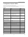
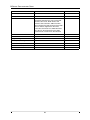
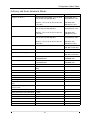
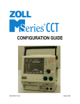
Configuration Option Tables
The following tables list the M Series option and their possible values.
An asterisk (“*”) refers to features that are currently not implemented on the M Series products. These features will
only operate in accordance with their pre-configured default settings (listed below).
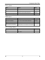
General
Feature
Options
Default
Selected Language
English, Other
English
Notch Filter (ECG)
50, 60 Hz
60 Hz
Allow Card Erase
Yes/No
Yes
Display Elapsed Time
Yes/No
AED: Yes
Manual Advisory: No
* Voice Markers Enabled
Yes/No
No
Set Report Restart Delays
Set/Review
Set/Review
Summary Report Restart Delay
5, 15, 30, 90 minutes, 1.5 days
15 minutes
Trend Report Restart Delay
5, 15, 30, 90 minutes, 1.5 days
15 minutes
Print 12 Lead 4x3
None, 1 Copy, 2 Copies
None
* Auto Self-Test TIme-out Period
No Test, 7, 8, 9, 10, 11, 12, 13, 14, 15, 16, 17,
18, 19, 20, 21, 22, 23, 24, 25, 26, 27, 28, 29,
30 days
No test
Async Softkey in Pace Mode
Yes/No
Yes
Code Markers
(Defib Code Markers, Monitor Code
Markers, Pace Code Markers)
Config/Review
Config/Review
Device Identifier
0 through 9, A through Z, blank, and “_” inclusive
for each digit
00000000
Manual Mode Passcode
0 through 3 inclusive, for each digit
000
Configuration Mode Passcode
0 through 3 inclusive, for each digit
00000000
Display Lead on Power-Up
Paddles/Pads, I, II, or III
Paddles/Pads
Frequency Response
0.5 - 21 Hz, 0.5 - 27 Hz, 1 - 21 Hz
0.5 - 21 Hz
QRS Volume on Power-Up
Midrange, OFF
Midrange
Pace Rate Setting on Power-Up
30 through 102 ppm (increments of 4 ppm)
70 ppm
Enable Pacer Detection
Yes/No
Yes
Gain on Power-Up (ECG)
AGC, 0.5 cm/mV, 1 cm/mV, 1.5 cm/mV, 2 cm/
mV
AGC
Report Memory Card Errors
Yes/No
Yes
Enable Leads Off
Yes/No
Yes
Upload Baud Rate
9600 bps, 38400 bps, 115200 bps
38400 bps
Trending Report Zoom Level
All, 5 min., 10 min., 15 min., 30 min., 60 min.
All
Trending Enabled
Yes/No
Yes
Battery Type Used
PD 4410, XL Battery
PD 4410
Alarm Limits at Power-Up
Set/Review
Set/Review
Alarms Active at Power-Up
Yes/No
No
25
000
M SERIES CONFIGURATION GUIDE
Feature
Options
Default
Low Battery Tone
1, 5 minutes
1 minute
Clock Synchronization
Set/Review
Set/Review
Time Zone
Azores, Middle Atlantic, S. America Eastern,
AST Atlantic, EST Eastern, CST Central, MST
Mountain, PST Pacific, AKST Alaska, HST
Hawaiian, Samoa, Dateline, GMT Greenwich,
CET Central Europe, EET Eastern Europe, MSK
Moscow, Arabian, Afghanistan, West Asia,
Central Asia, Southeast Asia, AWST Australian
West, Korean, ACST Australian Cent, AEST
Australian East, Central Pacific, New Zealand
EST Eastern
Dial Location
Hawaii, Colorado
Colorado
Dial Prefix
8 digits
(none)
Daylight Savings
Yes/No
No
Card Capacity Message Enabled
Yes/No
No
Erase Card Prompt at Pwr Off
Yes/No
No
Remove Card Prompt at Pwr Off
Yes/No
No
Sync Defib Excluded
Yes/No
No
26
Configuration Option Tables
Advisory and Semi-Automatic Modes
Feature
Options
Default
Energy Level: Shock 1
Damped Sine Wave (DSW): 1-10, 15, 20, 30,
50, 75, 100, 150, 200, 300, 360 J
Manual DSW: 200 J
Manual Biphasic: 120 J
Biphasic: 1-10, 15, 20, 30, 50, 75, 100, 120,
150, 200 J
AED DSW: 200 J
AED Biphasic: 120 J
Damped Sine Wave (DSW): 1-10, 15, 20, 30,
50, 75, 100, 150, 200, 300, 360 J
Manual DSW: 300 J
Manual Biphasic: 150 J
Biphasic: 1-10, 15, 20, 30, 50, 75, 100, 120,
150, 200 J
AED DSW: 200 J
AED Biphasic: 120 J
Damped Sine Wave (DSW): 1-10, 15, 20, 30,
50, 75, 100, 150, 200, 300, 360 J
Manual DSW: 360 J
Manual Biphasic: 200 J
Biphasic: 1-10, 15, 20, 30, 50, 75, 100, 120,
150, 200 J
AED DSW: 360 J
AED Biphasic: 200 J
Yes, No, Only in Semi-Auto
Manual: No
AED: Only in Semi-Auto
Stacked Shocks
1, 3
3
Display “DO CPR” Message
Yes, No, Only in Semi-Auto
Manual: No
AED: Only in Semi-Auto
CPR Message After Shock
“IF NO PULSE, PERFORM CPR;”
“PERFORM CPR”
“IF NO PULSE,
PERFORM CPR”
CPR Message After No Shock Advised
“IF NO PULSE, PERFORM CPR;”
“PERFORM CPR”
“IF NO PULSE,
PERFORM CPR”
Duration of CPR Interval
1, 1.5, 2, 2.5, 3, 3.5 or 4 minutes
1 minute
Check Pulse
Yes, No, After Shock Only, After No Shock
Only
Yes
Restart Analysis After CPR
Yes, No
Yes
“CHECK PATIENT” Prompt
“CHECK PATIENT,” “PRESS ANALYZE”
“CHECK PATIENT”
Display ECG in Semi-Auto Mode
Yes/No
Yes
Store to Card in Auto Monitor Mode
Yes/No
Yes
Energy Level: Shock 2
Energy Level: Shock 3
Auto Analyze
Auto Charge in Advisory Mode
Yes/No
Yes
ECG Waveform to Card in Advisory
Mode
Yes/No
No
Audio Data Recording to Card in
Advisory mode
Yes/No
No
Enable Voice in Advisory Mode
Yes/No
No
Display Heart Rate in Semi-Auto Mode
Yes/No
No
Auto-Analyze on Power Up
Yes/No
No
Extra CPR Interval Before 1st Analysis
Yes/No
No
Duration of Extra CPR Interval
1, 1.5, 2, 2.5, 3, 3.5, or 4 minutes
1 minute
Enable 12-Lead in Semi-Auto Mode
Yes/No
Yes
AED Defib Ready Hold Time
15 seconds, 60 seconds
15 seconds
27
M SERIES CONFIGURATION GUIDE
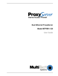
Manual Mode
Feature
Options
Default
Auto Generate Strips
Yes/No
Yes
Retain SYNC after Defib
Yes/No
No
Print 3 Leads When Leads Sel.
Yes/No
No
Auto Transmit After 12 Lead
Yes/No
No
Enable Data Relay
Yes/No
No
Fax/Communication Phone Numbers
Set/Review
Set/Review
12 Lead Analysis
Current 10 sec
Current 10 sec
12 Lead Printout
Standard/Cabrera
Standard
Print 12 Lead Measurements
Yes/No
No
12 Lead Fax Format
4x3 Standard, 4x3 Median Compl, 2x6
4x3 Standard
Print 2 Copies 12 Ld Analysis
Yes/No
No
Set Lead Groups
Set/Review
Set/Review
Custom Group 1
(3 leads)
For each lead:
I, II, III, aVR, aVL, aVF, V1, V2, V3, V4,V5,V6
Custom Group 2
(3 leads)
Custom Group 1:
II
III
aVF
Custom Group 2:
II
III
V1
12 Lead Freq Response
0.05 - 150 Hz 4x3, 0.05 - 150 Hz Cont.,
0.05 - 40 Hz 4x3
0.05 - 150 Hz 4x3
Lead Group Default
Standard, Custom Group 1, Custom Group 2
Standard
Print 12 Lead Interpretation
Yes/No
Yes
Defib Default to Pads
Yes/No
No
Cell Phone Type
Motorola, Nokia, NEC, OKI, Sony, Ericsson
Motorola
Basic Auto Energy Escalation
Yes/No
No
MUSE Site and Location
Site: 01 - 32
Location: 001 - 600
Site: 01
Location: 001
12 Lead Secs Per Lead
2.5, 5.0, 7.5, 10.0 seconds
2.5 seconds
12 Lead Print Speed
25 mm/sec, 50 mm/sec
25 mm/sec
28
Configuration Option Tables
EtCO2 Option
Feature
Options
Default
EtCO2 Options
Set/Review
Set/Review
Default EtCO2 Units
mmHg, kPa, %
mmHg
Displayed Zoom Level
(in mmHg): 0-12.5, 0-25, 0-50, 0-75, 0-100
(in kPa): 0-1.7, 0-3.3, 0-6.6, 0-10.0, 0-13.3
0-50 mmHg
0-6.6 kPa
Default EtCO2 Comp Setting
None, O2, N2O, O2 & N2O
None
EtCO2 Average On Power Up
1 breath, 10 seconds, or 20 seconds
10 seconds
Feature
Options
Default
NIBP Units
mmHg, kPa
mmHg
NIBP Auto Interval Default
2.5, 5, 10, 15, 20, 30, 45, 60, 90, 120 minutes
30 minutes
NIBP Option
Trigger NIBP Meas on BP Alarm
Yes/No
Yes
Trigger NIBP Meas on HR Alarm
Yes/No
No
NIBP First Inflate Pressure Default
(in mmHg): 120, 140, 160, 180, 200, 220, 240, 260
(in kPa): 16.0, 18.7, 21.3, 24.0, 26.7, 29.3, 32.0, 34.7
160 mmHg
Feature
Options
Default
Message Enabled
Yes/No
Yes
Threshold
(in mV): 0.8, 0.9, 1.0, 1.1, 1.2, 1.3, 1.4, 1.5, 1.6, 1.7,
1.8, 1.9, 2.0
1.5 mV
PTCA Settings Option
29
M SERIES CONFIGURATION GUIDE
30