1
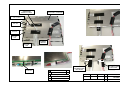
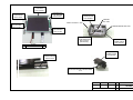
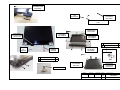
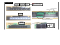
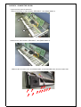
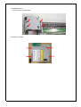
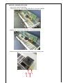
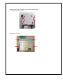
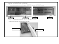
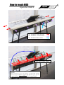
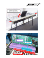
Service Man
anual
OASYS 76 / OASYS 88
Part2 Appendix
CONTENTS
(APPENDIX)
PARTS DIAGRAMS
LCD
: Page 2 - 4
PAD
: Page 5
Joystick
: Page 6
Vector Joystick : Page 7
How to change OASYS 76 CD-RW unit : Page 8 - 9
How to change OASYS 88 CD-RW unit : Page 10 - 11
CAUTION : OASYS FRONTPANEL SHIELD FORM: 12
Using the OASYS Internal Calibration Application: 13
How to reach HDD: Page14-24
5th Edition
Issued date : Oct.12, 2006
Issued by : KORG INC.
500540026600
SHILED FORM
65TS15-1.5 L=30mm
500313006200
TOUCH PANEL LCD MSA2021
ALUMINUM TAPE
(NOT A PART)
●
200046362421
KLM-2492
A26
A5
●
A26
A5
200046362417
KLM-2425
A26
A5
A26
A5
A26
500545050940
FFC HNS3463
67.3mm
500475003420
HARNESS
HNS-3420
500545050910
FFC HNS3460
74.7mm
A5
5mm
5mm
A5
A5
A5
200046362417
KLM-2425
500550022700
LCD CABLE COVER
1 KOC-F41209
SCREW
●
PLAX B ZMC 2×5
500550022800
LCD CABLE COVER
2 KOC-F41210
2
Ready-Made TAPE
DRAWN
A26
TAPE W=26mm
TAMURA
A5
TAPE W= 5mm
CHECKED
APPROVED
MODEL
TITLE
KORG INC.
NO.
X−2100/2160
LCD UNIT 1
3
500641041937
LCD TRAY
KOC-C20430
500630042300
LCD SPACER
KOC-F41237
500630042300
LCD SPACER
KOC-F41237
500646099500
HINGE GUIDE
KOC-E40639
GREASE
RG-103R
INSIDE GREASE RG-103R
500630042300
LCD SPACER
KOC-F41237
INSIDE GREASE RG-103R
500630042300
LCD SPACER
KOC-F41237
500641041933
GUIDE RESEPTOR
KOC-C41406
(BACK SIDE)
500641041932
HINGE ANGLE
KOC-C41405
SCREW
FE B BZMC 3*6
4
500646099700
HINGE COVER
KOC-E40638
500500035900
HINGE CUSHION
KOC-F41208
A5
HEXAGON SOCKET HEAD SCREW
4*10
DRAWN
CHECKED
TAMURA
APPROVED
MODEL
TITLE
KORG INC.
NO.
X−2100/2160
LCD UNIT 2
4
500641041951
LCD FRAME A ASSY
KOC-H30290
500646099600
CAP
KOC-E40641
500641041947
LCD FRAME D
KOC-C30684
DOUBLE-COATED ADHESIVE
TAPE
500641041927
KORG PLATE 5
KOC-C41155-5
500641041946
LCD FRAME C
KOC-C30683-2
500550022700
LCD CABLE COVER
1 KOC-F41209
500641041945
LCD FRAME B
KOC-C30683-1
SCREW
SH0308BNI(AZUMA)3*8
500545050910
FFC
HNS-3460
4
500641041947
LCD FRAME D
KOC-C30684
500475003420
HARNESS
HNS-3420
A5
SCREW
SH0308BNI(AZUMA)3*8
4
500500035800
LCD CUSHION
KOC-F41216
500500035800
LCD CUSHION
KOC-F41216
LOCTITE 242
DRAWN
CHECKED
TAMURA
APPROVED
MODEL
TITLE
KORG INC.
NO.
X−2100/2160
LCD UNIT 3
5
PAD related parts
500646097700
PAD FRAME
KOC-E30371-1
500646097500
PAD BUTTON
KOC-E40623
50052500200
0
FERRITE
(NOTE) It is actually a magnet but
it is wrongly listed as FERRITE
CORE
tear along perforation
KLM-2417-91/2505-63
500646097600
PAD CUSSION
KOC-E30375
200046362421
PCB ASSY KLM-2421/22/92/2651
LED(pre-installed)
200046362417
PCB ASSY
KLM-2417-91/2505-
CLOSEUP
LED(pre-installed)
X-2160 JSPanel ASSY
X-2100 JSPanel ASSY
500641041944
X-2100 EMI ANGLE JS KOC-C41410
KLM-2555(a part of
200046362417 PCB
ASSY KLM-241791/2505 63)
KLM-2555(a part of
200046362417 PCB ASSY
KLM-2417-91/2505-63)
500475003438
HARNESS HNS-3438
500475003432
HARNESS HNS-3432
500641041905
X-2100 JS SUPPORT R
KOC-C30662
500641041904
X-2100 JS SUPPORT L
KOC-C30660
C
500641041944
X-2100 EMI ANGLE JS KOC-C41410
500475003450
HARNESS HNS-3450
2100 JoystickASSY
500641041906
X-2160 JS SUPPORT
R KOC-C30661
500641041904
X-2100 JS SUPPORT
L KOC-C30660
C
2100 JoystickASSY
500475002197
HARNESS HNS-2197
BOARD IN
500475002197
HARNESS HNS-2197
BOARD IN
A5
500641041258
X-311/312 FSR
KLM-2556(a part of 200046362417 PCB METAL KOC-C41000
ASSY KLM-2417-91/2505-63)
C
Screw
Qty.
BT B BZMC 3x8
16
CoatingClip CS-6
1
500646064700
X-311BK CONTROL
KNOB ASSY
C
500415005000
KX-2100 SENSER (BLACK)
REVISAL
MARK
REVISAL REASON
REVISAL DATE
REVISAL BY APPROVED
500641041258
X-311/312 FSR
METAL KOC-C41000
KLM-2556(a part of 200046362417
PCB ASSY KLM-2417-91/2505-63)
500540027500
GASKET E02S080070ET-110
L=110
DRAWN
CHECKED
Screw
Qty.
BT B BZMC 3x8
16
CoatingClip CS-6
1
APPROVED
田村
武田
2005/5/27
2005/5/31
KORG.INC
500475003432
HARNESS
HNS-3432
MODEL
TITLE
NO.
X−2100/2160
JSパネル加工図
KOE−F32028
6
VN BZMC 9
500641041908
X-2100 VR PLATE KOC-C41378
VN BZMC 9
500641041908
X-2100 VR PLATE KOC-C41378
2
1
KLM-2304
VJS ASSY
500646096600
X-2100 JS GUIDE 1
KOC-E40619
KLM-2305
VJS ASSY
500641041954
X-2100 JS PIN
KOC-C41418
500641041907
X-2100 JS GUIDE
2 KOC-C41379
500550023000
X-2100 JS MASK
KOC-F41056
4
3
1
500646096500
X-2100 JS SHAFT
KOC-E40618
②
500646096700
X-2100 JS BOX
KOC-E30367
500641041953
X-2100 JS LEVER
KOC-C41417
A5
3
Screw
Qty.
BT B BZMC 3x8
4
4
OASYS76 : CHANGE THE CD-RW
1.Open the front panel of OASYS76.
Remove the screw of ①OP COVER, ②EMI ANGLE 1 and ③EMI ANGLE 2.
1
2
3
2.Remove the ①OP COVER, ②EMI ANGLE 1 and ③EMI ANGLE 2 .
3.Remove the 12 screws of the JOYSTICK-PANEL and KEYBOARD ASSY from the bottom side.
KEYBOARD ASSY.
and remove the CD-RW UNIT.
5.Change the CD-RW.
OASYS88 : CHANGE THE CD-RW
1.Open the front panel of OASYS88.
Remove the screw of ①OP COVER, ②EMI ANGLE 1 and ③EMI ANGLE 2.
1
2
3
2.Remove the ①OP COVER, ②EMI ANGLE 1 and ③EMI ANGLE 2 .
3.Remove 4 screws of the JOYSTICK-PANEL-ASSY from the bottom side.
4.Remove the cables , Remove the JOYSTICK-PANEL-ASSY.
and remove the CD-RW UNIT.
5.Change the CD-RW.
CAUTION : OASYS FRONTPANEL SHIELD FORM
The shield form is pasted to the front panel. (OASYS76 :4 pieces , OASYS88 :5 pieces)
shield form
shield form
shield form
Please do not peel off the shield form when you insert the corner panel.
Troubre occurs when the shield form falls in the PCB.
FRONT PANEL
CORNER PANEL
shield form
Using the OASYS Internal Calibration Application
BE VERY CAREFUL!
5. Press the INC/DEC key to browse through the test
categories (the name is shown on the top of the
screen).
DO NOT TOUCH ANY BUTTONS OR CONTROLS
OTHER THAN THE ONES NOTED BELOW.
You will step through “Switch & LED,” “LCD,” and
then “A/D Converter.”
TOUCH ONLY ONE CONTROLLER AT A TIME. DO
NOT MOVE MULTIPLE KNOBS OR FADERS.
6. Stop when you see the “A/D Converter” category.
Important precautions
Dismissing error messages
At any point, if you move a different controller from
the one that the application expects, an error message
will appear. If this occurs, simply dismiss the error
message by touching the screen, and then continue.
When is calibration necessary?
Each OASYS is calibrated before leaving the factory,
using this hidden, internal application. The resulting
calibration data is stored on the internal hard disk.
In general, it should not be necessary to re-calibrate,
unless:
• controls have drifted over time (possible, but is not
expected to be an issue), or
• the OASYS hard drive has been formatted.
Formatting the OASYS hard drive erases the stored
calibration data. Without this, physical controls may
still operate correctly–but to ensure the best
performance, it will be necessary to re-calibrate.
This is one of the reasons that Korg recommends
against formatting unless it is absolutely necessary.
Calibrating the physical controls
1. Turn on the unit, wait for the Combi screen to
appear.
2. Press and hold the following four buttons, in the
specified order, so that at the end all four buttons
are held down: EXIT, 2, ENTER, and FUNCTION.
(Other orders will work, but one in particular - starting
with ENTER + 2 - brings up a dialog box first, and
appears to put the system in a slightly strange state.)
7. Press the front-panel ENTER button. You'll enter
the “Ribbon Controller” section.
8. Press your finger along the full width of the
ribbon, from left to right. “OK” will appear on the
screen.
9. After seeing 3 OKs in all, lift up your finger, and
press ENTER. At this point, the calibration data
for the ribbon is updated.
For all of the controllers below (except the rotary
encoder), follow the same procedure: move the
controller to its extreme max and min positions until
the display shows OK for all values, and then press
ENTER to proceed to the next section.
You can also use the FF>> and <<REW buttons to
move back and forth between the tests. If you find that
you are unable to get an OK message for a particular
test, use FF>> and <<REW to exit and re-enter the test,
and try it again.
10.Joystick: move up and down, left to right.
11.Vector Joystick: move all around, in a circle.
12.Knobs, faders, and value slider: move each one to
its max and min positions.
13.Rotary encoder (value dial): this test is slightly
different. Rotate the encoder clockwise to exactly
+30, and then counter-clockwise to exactly -30.
14.Tempo knob: move to max and min positions.
After the Tempo knob section, the tests proceed
automatically to the foot switch/pedal section. If you
do not have all three foot switches/pedals connected,
you can complete the calibration simply by turning off
the power.
Calibration data is stored after each test
3. Wait for a few seconds, until some strange text
appears on the screen, over-writing the main
display. (For those who are curious, these are
Linux command-line messages.) You can release
the buttons at this point.
The calibration data is stored each time you press
ENTER after completing an individual test. If you only
need to calibrate the Ribbon, Joystick, and Vector
Joystick, for instance, you can simply turn off the
power after pressing ENTER at the end of the Vector
Joystick test.
Wait about 10 more seconds. At the end of this time,
the test application appears.
Aftertouch calibration (76-note only)
The calibration application includes a S/PDIF I/O test,
and at startup it automatically checks to see if a
S/PDIF cable is connected. If not, the screen will
display a prompt: “Connect S/PDIF Cable.” For
calibrating the physical controls, it’s completely
unnecessary to have S/PDIF connected–but you’ll
need to dismiss the message before proceeding:
For 76-note keyboards only, aftertouch calibration is in
the “Key & AfterT” section. Calibration for the 88-key
is completely different, and not accessible via this
application.
Document version history
4. Touch anywhere on the screen to clear the Connect
S/PDIF Cable message.
1.0: Initial version
Note the text “Fan Control” at the top of the screen.
This shows the current test section.
1.2: Added “When is calibration necessary?” section
1.1: Added step to clear Connect S/PDIF message
How to reach HDD
Open
Open the OASYS
Drawn by H.Kudou
Page 1/5
Aug 21, 2006
(1) Remove 4 side screws.
(2) Remove 7 rear screws.
(3) Remove Rear cover.
Open the Corner Panel.
[Note]
With a little support of pulling up the LCD will be
a great help to Open/Close the Corner Panel.
Open
(1)
(2)
Page 2/5
Remove 5 screws.
Close the Corner Panel.
[Note]
Pulling up the LCD is effective
when closing the Corner Panel,
Open
(1) Tighten up 2 screws.
(2) Open the Front Panel.
PCB Cover
OP Cover
2100 EMI Angle-2
Page 3/5
Open
(1)
(2)
(3)
Page 4/5
Remove 2 screws from OP cover.
Remove OP cover.
Remove 4 screws from PCB cover.
Flip “2100 EMI Angle-2”.
Open
Remove PCB Cover.
HDD is here.
Page 5/5
HDD
Fixed with 4 screws.
How to reach HDD
Close
Close the OASYS
Page 1/5
Be careful!
Insert to set PCB Cover.
Check
Flip back “2100 EMI Angle-2”.
Close
Check if the PCB Cover has correctly been set.
PCB Cover must be set under the Corner Panel.
NG
(1) Keep pushing PCB Cover toward the rear,
tighten up 4 screws to PCB Cover
(2) Set OP Cover.
(3) Tighten up 2 screws to OP Cover tenderly.
OK
Page 2/5
Close
Check if the Harness has correctly been tied up.
Check
Close the Front Panel.
Page 3/5
Close
(1) Remove 2 side screws.
(2) Open Corner Panel.
(1) Tighten up 5 screws.
(2) Close the Corner Panel.
Page 4/5
Close
(1) Set Rear cover.
(2) Tighten up 7 rear screws.
(3) Tighten up 4 side screws.
Page 5/5