1
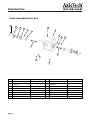
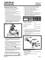
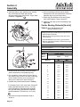
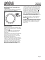
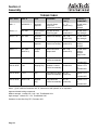
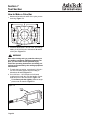
Carrier Box Assembly
Ensemble de carter de nej-de-pont
Maintenance Manual MM5.3
Manuel de maintenance MM5.3
Models / Mòdeles
A4 3200E 2033 293
A4 3200E 2033 292
Issued 6-04
Edité Mai 04
Service Notes
Before You Begin
This manual provides instructions for AxleTech
International’s Carrier Box Assembly. Before you
begin procedures:
1. Read and understand all instructions
and procedures before you begin to service
components.
2. Read and observe all Caution and Warning safety
alerts that precede instructions or procedures you
will perform. These alerts help to avoid damage to
components, serious personal injury, or both.
3. Follow your company’s maintenance and service,
installation, and diagnostics guidelines.
4. Use special tools when required to help avoid
serious personal injury and damage to
components.
Safety Alerts, Torque Symbol
and Notes
!
!
WARNING
CAUTION
A Warning alerts you to an
instruction or procedure that
you must follow exactly to
avoid serious personal
injury.
A Caution alerts you to
an instruction or procedure
that you must follow
exactly to avoid damage
to components.
The torque symbol alerts
you to tighten fasteners to
a specified torque value.
NOTE:
A Note provides information
or suggestions that help
you correctly service a
component.
The instructions contained in this Field Maintenance
Manual are intended for use by skilled and
experienced mechanics knowledgeable in the
installation, repair and replacement of AxleTech
Carrier Box Assembly. Installation, maintenance and
replacement of AxleTech Carrier Box Assembly
require a high degree of skill and experience. The
consequences of improper installation, maintenance
or replacement are grave and can result in vehicle
drive failure and possible injury to or death of persons.
AxleTech does not authorize anyone other than highly
skilled and experienced individuals to attempt to utilize
the instructions contained in this Manual for the
installation, maintenance or replacement of AxleTech
Carrier Box Assembly and AxleTech shall have no
liability of any kind for damages arising out of (or in
connection with) any other use of the information
contained in this Manual.
Additional Publications
For AxleTech service manuals, please contact:
1-877-877-9717 or visit our website at
www.axletech.com.
How To Order
Order items from AxleTech International.
Phone orders are also accepted by calling AxleTech
International’s Customer Service Center at
877-547-3907 or send a fax to 866-547-3987.
For ArvinMeritor brake manuals, please contact their
Customer Service Center at 1-800-535-5560 or visit
their website at www.arvinmeritor.com.
Asbestos and Non-Asbestos Fibers
!
ASBESTOS FIBERS WARNING
!
NON-ASBESTOS FIBERS WARNING
The following procedures for servicing brakes are recommended to
reduce exposure to asbestos fiber dust, a cancer and lung disease
hazard. Material Safety Data Sheets are available from AxleTech.
The following procedures for servicing brakes are recommended to
reduce exposure to non-asbestos fiber dust, a potential cancer and lung
disease hazard. Material Safety Data Sheets are available from Meritor.
Hazard Summary
Hazard Summary
Because some brake linings contain asbestos, workers who service brakes must
understand the potential hazards of asbestos and precautions for reducing risks.
Exposure to airborne asbestos dust can cause serious and possibly fatal diseases,
including asbestosis (a chronic lung disease) and cancer, principally lung cancer
and mesothelioma (a cancer of the lining of the chest or abdominal cavities). Some
studies show that the risk of lung cancer among persons who smoke and who are
exposed to asbestos is much greater than the risk for non-smokers. Symptoms of
these diseases may not become apparent for 15, 20 or more years after the first
exposure to asbestos.
Accordingly, workers must use caution to avoid creating and breathing dust when
servicing brakes. Specific recommended work practices for reducing exposure to
asbestos dust follow. Consult your employer for more details.
Most recently manufactured brake linings do not contain asbestos fibers. These
brake linings may contain one or more of a variety of ingredients, including glass
fibers, mineral wool, aramid fibers, ceramic fibers and silica that can present
health risks if inhaled. Scientists disagree on the extent of the risks from
exposure to these substances. Nonetheless, exposure to silica dust can cause
silicosis, a non-cancerous lung disease. Silicosis gradually reduces lung
capacity and efficiency and can result in serious breathing difficulty. Some
scientists believe other types of non-asbestos fibers, when inhaled, can cause
similar diseases of the lung. In addition, silica dust and ceramic fiber dust are
known to the State of California to cause lung cancer. U.S. and international
agencies have also determined that dust from mineral wool, ceramic fibers and
silica are potential causes of cancer.
Accordingly, workers must use caution to avoid creating and breathing dust
when servicing brakes. Specific recommended work practices for reducing
exposure to non-asbestos dust follow. Consult your employer for more details.
Recommended Work Practices
1. Separate Work Areas. Whenever feasible, service brakes in a separate area
away from other operations to reduce risks to unprotected persons. OSHA has set
a maximum allowable level of exposure for asbestos of 0.1 f/cc as an 8-hour timeweighted average and 1.0 f/cc averaged over a 30-minute period. Scientists
disagree, however, to what extent adherence to the maximum allowable exposure
levels will eliminate the risk of disease that can result from inhaling asbestos dust.
OSHA requires that the following sign be posted at the entrance to areas where
exposures exceed either of the maximum allowable levels:
DANGER: ASBESTOS
CANCER AND LUNG DISEASE HAZARD
AUTHORIZED PERSONNEL ONLY
RESPIRATORS AND PROTECTIVE CLOTHING
ARE REQUIRED IN THIS AREA
2. Respiratory Protection. Wear a respirator equipped with a high-efficiency
(HEPA) filter approved by NIOSH or MSHA for use with asbestos at all times when
servicing brakes, beginning with the removal of the wheels.
3. Procedures for Servicing Brakes.
a. Enclose the brake assembly within a negative pressure enclosure. The
enclosure should be equipped with a HEPA vacuum and worker arm sleeves.
With the enclosure in place, use the HEPA vacuum to loosen and vacuum
residue from the brake parts.
b. As an alternative procedure, use a catch basin with water and a biodegradable,
non-phosphate, water-based detergent to wash the brake drum or rotor and
other brake parts. The solution should be applied with low pressure to prevent
dust from becoming airborne. Allow the solution to flow between the brake
drum and the brake support or the brake rotor and caliper. The wheel hub and
brake assembly components should be thoroughly wetted to suppress dust
before the brake shoes or brake pads are removed. Wipe the brake parts clean
with a cloth.
c. If an enclosed vacuum system or brake washing equipment is not available,
employers may adopt their own written procedures for servicing brakes,
provided that the exposure levels associated with the employer’s procedures
do not exceed the levels associated with the enclosed vacuum system or brake
washing equipment. Consult OSHA regulations for more details.
d. Wear a respirator equipped with a HEPA filter approved by NIOSH or MSHA for
use with asbestos when grinding or machining brake linings. In addition, do
such work in an area with a local exhaust ventilation system equipped with a
HEPA filter.
e. NEVER use compressed air by itself, dry brushing, or a vacuum not equipped
with a HEPA filter when cleaning brake parts or assemblies. NEVER use
carcinogenic solvents, flammable solvents, or solvents that can damage brake
components as wetting agents.
4. Cleaning Work Areas. Clean work areas with a vacuum equipped with a HEPA
filter or by wet wiping. NEVER use compressed air or dry sweeping to clean work
areas. When you empty vacuum cleaners and handle used rags, wear a respirator
equipped with a HEPA filter approved by NIOSH or MSHA for use with asbestos.
When you replace a HEPA filter, wet the filter with a fine mist of water and dispose
of the used filter with care.
5. Worker Clean-Up. After servicing brakes, wash your hands before you eat,
drink or smoke. Shower after work. Do not wear work clothes home. Use a vacuum
equipped with a HEPA filter to vacuum work clothes after they are worn. Launder
them separately. Do not shake or use compressed air to remove dust from work
clothes.
6. Waste Disposal. Dispose of discarded linings, used rags, cloths and HEPA
filters with care, such as in sealed plastic bags. Consult applicable EPA, state and
local regulations on waste disposal.
Regulatory Guidance
References to OSHA, NIOSH, MSHA, and EPA, which are regulatory agencies in
the United States, are made to provide further guidance to employers and workers
employed within the United States. Employers and workers employed outside of
the United States should consult the regulations that apply to them for further
guidance.
Recommended Work Practices
1. Separate Work Areas. Whenever feasible, service brakes in a separate area
away from other operations to reduce risks to unprotected persons.
2. Respiratory Protection. OSHA has set a maximum allowable level of
exposure for silica of 0.1 mg/m3 as an 8-hour time-weighted average. Some
manufacturers of non-asbestos brake linings recommend that exposures to
other ingredients found in non-asbestos brake linings be kept below 1.0 f/cc as
an 8-hour time-weighted average. Scientists disagree, however, to what extent
adherence to these maximum allowable exposure levels will eliminate the risk of
disease that can result from inhaling non-asbestos dust.
Therefore, wear respiratory protection at all times during brake servicing,
beginning with the removal of the wheels. Wear a respirator equipped with a
high-efficiency (HEPA) filter approved by NIOSH or MSHA, if the exposures
levels may exceed OSHA or manufacturer’s recommended maximum levels.
Even when exposures are expected to be within the maximum allowable levels,
wearing such a respirator at all times during brake servicing will help minimize
exposure.
3. Procedures for Servicing Brakes.
a. Enclose the brake assembly within a negative pressure enclosure. The
enclosure should be equipped with a HEPA vacuum and worker arm sleeves.
With the enclosure in place, use the HEPA vacuum to loosen and vacuum
residue from the brake parts.
b. As an alternative procedure, use a catch basin with water and a
biodegradable, non-phosphate, water-based detergent to wash the brake
drum or rotor and other brake parts. The solution should be applied with low
pressure to prevent dust from becoming airborne. Allow the solution to flow
between the brake drum and the brake support or the brake rotor and caliper.
The wheel hub and brake assembly components should be thoroughly wetted
to suppress dust before the brake shoes or brake pads are removed. Wipe
the brake parts clean with a cloth.
c. If an enclosed vacuum system or brake washing equipment is not available,
carefully clean the brake parts in the open air. Wet the parts with a solution
applied with a pump-spray bottle that creates a fine mist. Use a solution
containing water, and, if available, a biodegradable, non-phosphate, waterbased detergent. The wheel hub and brake assembly components should be
thoroughly wetted to suppress dust before the brake shoes or brake pads are
removed. Wipe the brake parts clean with a cloth.
d. Wear a respirator equipped with a HEPA filter approved by NIOSH or MSHA
when grinding or machining brake linings. In addition, do such work in an area
with a local exhaust ventilation system equipped with a HEPA filter.
e. NEVER use compressed air by itself, dry brushing, or a vacuum not equipped
with a HEPA filter when cleaning brake parts or assemblies. NEVER use
carcinogenic solvents, flammable solvents, or solvents that can damage brake
components as wetting agents.
4. Cleaning Work Areas. Clean work areas with a vacuum equipped with a
HEPA filter or by wet wiping. NEVER use compressed air or dry sweeping to
clean work areas. When you empty vacuum cleaners and handle used rags,
wear a respirator equipped with a HEPA filter approved by NIOSH or MSHA, to
minimize exposure. When you replace a HEPA filter, wet the filter with a fine mist
of water and dispose of the used filter with care.
5. Worker Clean-Up. After servicing brakes, wash your hands before you eat,
drink or smoke. Shower after work. Do not wear work clothes home. Use a
vacuum equipped with a HEPA filter to vacuum work clothes after they are worn.
Launder them separately. Do not shake or use compressed air to remove dust
from work clothes.
6. Waste Disposal. Dispose of discarded linings, used rags, cloths and HEPA
filters with care, such as in sealed plastic bags. Consult applicable EPA, state
and local regulations on waste disposal.
Regulatory Guidance
References to OSHA, NIOSH, MSHA, and EPA, which are regulatory agencies
in the United States, are made to provide further guidance to employers and
workers employed within the United States. Employers and workers employed
outside of the United States should consult the regulations that apply to them for
further guidance.
Table of Contents
Exploded Views
Center Assembly-Carrier Box..........................................................................................................................2
Carrier Assembly.............................................................................................................................................3
Section 1: Introduction
Identification ....................................................................................................................................................4
Descriptions.....................................................................................................................................................4
Section 2: Disassembly
Carrier Assembly Box......................................................................................................................................4
Disassembly From Vehicle..............................................................................................................................5
Carrier Box Assembly Disassembly ................................................................................................................5
Removal of The Carrier Assembly From The Carrier Box Assembly..............................................................5
Carrier Disassembly Procedures ....................................................................................................................6
Disassembly of the Differential Cases ............................................................................................................8
Carrier Box Final Disassembly........................................................................................................................8
Section 3: Prepare Parts for Assembly
Clean Ground or Polished Parts .....................................................................................................................9
Clean Parts With A Rough Finish....................................................................................................................9
Clean The Carrier Box Housing ......................................................................................................................9
Drying Cleaned Parts ......................................................................................................................................9
Preventing Corrosion ......................................................................................................................................9
Inspecting Parts ..............................................................................................................................................9
Cleaning The Breather ....................................................................................................................................9
Tapered Roller Bearings................................................................................................................................10
Pinions And Gears.........................................................................................................................................11
Main Differential Assembly ............................................................................................................................11
Output Shafts.................................................................................................................................................11
Repair Or Replace Parts ...............................................................................................................................11
Welding Repair ..............................................................................................................................................11
Removing Dri-Loc Fasteners.........................................................................................................................11
Installing Fasteners With Pre-Applied Adhesive ...........................................................................................12
Installing Original Or Used Fasteners ...........................................................................................................12
Apply Liquid Gasket Material ........................................................................................................................12
Flush Lube From The Carrier Box ................................................................................................................13
Gearset Information (Drive Pinion And Ring Gear Marks)............................................................................13
Section 4: Assembly
Assembling the Pinion Bearing Cage ...........................................................................................................14
Assembling the Differential Case ..................................................................................................................14
Installing the Drive Pinion .............................................................................................................................15
Installing the Differential Case Assembly......................................................................................................15
Carrier Bearing Preloads...............................................................................................................................16
Installing Carrier Assembly Into Carrier Box .................................................................................................17
Torque Table..................................................................................................................................................18
Section 5: Adjustments
Checking the Ring Gear Backface Runout ...................................................................................................19
Adjusting the Gearset Backlash....................................................................................................................19
Adjusting Tooth Contact Pattern of the Gearset ...........................................................................................20
Section 6: Lubrication
Magnet Drain Plug ........................................................................................................................................23
Breather.........................................................................................................................................................23
Seals .............................................................................................................................................................23
Oil Level ........................................................................................................................................................23
Carrier Oil Box Recommendations ...............................................................................................................23
Approved Oil Listings ....................................................................................................................................23
Approved Grease Recommendations for Carrier Box Assembly..................................................................23
Section 7: Tool Section
How to Make a Yoke Bar ..............................................................................................................................24
Exploded View
Center Assembly-Carrier Box
11
10
9
8
1
7
16
6
12
13
14
5
4
2
3
15
Item
Description
1
HSG Assy-Carrier Box
2
3
4
5
Quantity
Item
Description
9
Washer-Flat
12
10
Yoke-Output
2
Capscrew
12
11
Locknut
2
Shaft-Output L.H.
1
12
Lock
2
Shaft-Output R.H.
1
13
Capscrew
4
6
Bearing-Ball
2
14
Plug-Fill Level
1
7
O-Ring
2
15
Plug/Drain Magnetic
1
8
Cage-Output
2
16
Breather Assy
1
Page 2
Seal
Quantity
1
2
Exploded View
Carrier Assembly
27
24
25
26
22
21
23
1
19
2
18
3
17
4
20
5
16
6
7
8
9
10
15
11
14
12
13
Item
Description
1
Diff.-Carr & Cap Assy
2
3
Quantity
Item
Description
Quantity
1
15
Lock
1
Cup-Bearing
1
16
Cotter
2
Bearing Cone
1
17
Ring-Brg Adj, Fin
2
4
Shim .012 inch
As Required
18
Cup-Bearing
2
5
Shim .008 inch
As Required
19
Cone-Bearing Assy
2
6
Pinion-Spiral Bevel
1
20
Capscrew
16
7
Bearing Cone-Outer
1
21
Case Assy Diff
1
8
Cup-Bearing
1
22
Washer-Side Gear Thrust
2
9
O-Ring
1
23
Side Gear-Diff
2
10
Cage Assy-Input
1
24
Washer-Pinion Thrust
4
11
Seal Assy
1
25
Pinion-Diff
4
12
Yoke Input
1
26
Spider-Diff
1
13
Locknut
1
27
Gear Assy-Spiral Bevel
1
14
Capscrew
2
Page 3
Section 1
Description
Carrier Box Service Manual
Figure 1.1
Identification:
CARRIER BOX ASSEMBLY
IDENTIFICATION
TAG LOCATION
To determine the exact axle model and specification,
refer to the identification tag located on the carrier box
assembly as shown in Figure 1.1.
Description:
AxleTech International carrier box assembly incorporates a single reduction spiral bevel gearing carrier
assembly mounted in a carrier box housing for remote
drive axle assembly. Figure 1.2.
AxleTech
The AxleTech carrier box assembly permit the output
shafts to carry torsional and axial loads.
MODEL
A43200E2033292
CUST No.
• Power is transmitted by the Spiral Bevel gear set in
the carrier to the output shafts.
SERIAL No.
RATIO
2.92:1.0
DATE
• The power is then transmitted into associated
Chaincases with planetary hub reductions for
final vehicle drive.
Figure 1.2
CROSS-SECTION OF CARRIER BOX ASSEMBLY
Spiral Bevel Gear
Carrier Box
Ball Bearing
Output Seal
Output Shaft
Output Yoke
Lock Nut
Output Yoke
O-Ring
Output Ball Bearing Cage
Shims
Input Seal
Pinion Cage
Input Yoke
Spiral Bevel Pinion
Page 4
Section 2
Disassembly
Disassembly From Vehicle:
!
WARNING
To prevent serious eye injury, always wear
safe eye protection when you perform vehicle
maintenance or service.
Park the vehicle on a level surface. Block the
wheels to prevent the vehicle from moving.
Support the vehicle with safety stands. Do not
work under a vehicle supported only by jacks.
Jacks can slip and fall over. Serious personal
injury and damage to components can result.
OEM service instructions should be followed
when servicing these components under the
vehicle.
NOTE: Any pre-cleaning on vehicle to remove
dirt/grease or corrosive material should be per vehicle manufacturer recommendations. Care should be
taken to cover the carrier box breather to limit additional contamination during pre-cleaning process.
1. Remove the drain plug (3/4"-14) to drain the
lubricant into a suitable container. Note amount
of metal on the magnetic drain plug and clean
drain plug.
2. Discard the drained lubricant in an environmentally responsible manner, according to state
and/or (EPA) recommendations.
3. Disconnect the vehicle propshaft from the carrier
box input yoke and both output yoke prop shafts
from each chain case assembly input yoke per
vehicle manufacturer recommendations.
Care should be taken so personal injury
does not occur.
4. Support the carrier box assembly for safe
removal from the vehicle chassis frame.
5. Remove the carrier box assembly from the
vehicle per vehicle manufacturer recommended
procedures and place on adequate work bench
to prepare for disassembly.
Carrier Box Assembly Disassembly:
Initial disassembly required for carrier assembly
removal for inspection or service requires the
removal of the (2) output shafts assemblies. Each
output shaft assembly may be removed as a total
subassembly.
1. To remove each output shaft assembly, remove
the (2) M6x1.0 capscrews and lock tab located
above the output yokes on the carrier box
assembly.
2. Unscrew counter clockwise the output ball
bearing cage that retains the shaft assembly on
each assembly.
3. Remove as a sub-assembly the output yoke,
yoke lock nut, bearing cage, output shaft, ball
bearing, and O-ring and set on the work bench.
NOTE: The lock nut was assembled with a thread
lock applied to the M24x1.5 nut threads.
4. To remove the yoke lock nut, set the assembly in
a vise to restrain the yoke ears. Use wrench to
loosen lock nut. An optional method to remove
the yoke lock nut is to use a yoke bar. This
procedure and yoke bar tool description is
shown in the tool section of this manual.
5. Remove the yoke from the shaft assembly.
6. Remove the bearing cage, oil seal, O-ring from
the output shaft assembly and set aside for later
cleaning, inspection and reassembly.
!
WARNING
Observe all warnings and cautions provided by
the press manufacturer to avoid damage to
components and serious personal injury.
NOTE: Care should be taken not to press on the
ball bearing outer journal as damage to bearing
could occur.
7. Remove the ball bearing from the output shaft
by placing these components vertically in a
hydraulic press and use a suitable tube cylinder
of correct diameter to touch the inner bearing
race only to allow the bearing to be pressed off
the output shaft. Prior to actually pressing the
bearing, recommend a suitable container be
placed below the area where the output shaft
will be pressed out of the ball bearing and the
container have some soft impact material so the
shaft is not damaged when pressed thru the ball
bearing and personal injury does not occur.
Place these components on the workbench for
later cleaning, inspection, and reassembly.
Removal Of The Carrier Assembly From
The Carrier Box Assembly:
NOTE: These capscrews have thread compound
applied to the threads during production assembly.
1. Loosen and remove the (12) M12X1.25
capscrews with washers from the carrier
assembly to carrier box mounting pattern.
!
WARNING
Take care when using lifting devices. When
you use a lifting strap, inspect the strap for
damage before you use it. Do not use a lifting
strap to shock load or drop load a component.
Serious personal injury and damage to
components can result.
Page 5
Section 2
Disassembly
2. Attach the lifting strap and lifting device to the
carrier input yoke in a safe method to apply
tension to the strap. See Figure 2.1.
Figure 2.2
Figure 2.1
Figure 2.3
3. Use (2) M12x1.25 capscrews in the threaded
holes at top and bottom or carrier to loosen
and separate the carrier assembly from the
carrier box.
4. Remove the carrier assembly from the carrier
box assembly and place safely and secure in
either a carrier stand or on the workbench so the
carrier will not fall and cause personal injury or
component damage.
Carrier Disassembly Procedure:
Should the carrier upon inspection require
disassembly, please follow the following steps after
the carrier is securely retained for safe disassembly
so no personal injury can occur. A carrier stand that
will permit the carrier assembly is recommended as
the carrier assembly must be rotated to teardown
and built from both top and bottom access areas of
the assembly.
!
Figure 2.4
WARNING
To prevent serious eye injury, always wear safe
eye protection when you perform vehicle
maintenance or service.
1. Use a small lb-in torque wrench at input yoke or
else attach a spring scale to the yoke and rotate
the yoke by pulling on the spring scale. Observe
and record the total preload measurement value
indicated on the spring scale. Figure 2.2.
2. Measure and record the ring gear backface
runout Figure 2.3 and the gearset backlash
Figure 2.4 values.
3. Using a snap ring pliers, remove the snap ring
from the carrier input yoke (if used).
Page 6
NOTE: exploded view shows item #13 as a lock nut
which is available on later carrier designs. Early
production design uses a snap ring and washer to
retain the input pinion yoke.
Section 2
Disassembly
The input pinion lock nut can be removed using the
same (2) options as the output shaft lock nut in item
#4 (Page 5) of the carrier box disassembly instructions above. When a lock nut is fitted, thread compound has been used on pinion nut threads during
production assembly.
9. Remove the adjusting ring and bearing cup from
the bearing cap side. Figure 2.5.
Figure 2.5
1. Remove the carrier input yoke.
2. Remove the oil seal from the input cage
assembly and discard.
3. Remove the (2) capscrews (M6X1.0) and lock
plate from the carrier input bearing cage that
retain input bearing cage in carrier assembly.
4. Remove the bearing cage O-ring and taper
bearing cup by un-screwing in a counter
clockwise direction.
5. Remove the spiral bevel pinion with (2) bearing
cones and shims as an assembly. The pinion
bearings should be removed by using a hydraulic
press with a similar procedure as item #7 (Page
5) in removing the ball bearing from the output
shafts above. A suitable bearing puller must also
be used behind the cone to remove the bearing
cones. The puller must fit correctly under the
inner face of the cone to avoid damage to the
cone. Measure, record and save for later
re-assembly any shims removed from behind
inner bearing cone assembly on the spiral
bevel pinion.
10. Tilt the differential case and ring gear assembly
slightly toward the bearing cage saddle. Carefully
remove the differential case and ring gear assembly and set on the work bench.
Figure 2.6.
Figure 2.6
6. Rotate the carrier assembly over for the ring
gear facing upwards.
7. Remove the cotter pin that lock the ring gear
bearing adjusting ring and loosen the
adjusting rings.
8. Remove the differential bearing cap bolts and
cap from the carrier assembly.
11. To remove the inner bearing cup from the carrier
housing and the outer bearing cup from the pinion
bearing cage. Use a press and sleeve or a small
drift and brass hammer to remove the bearing
cup. Do not damage the ring journals when you
remove the bearing cup.
Page 7
Section 2
Disassembly
Disassembly of the Differential
Cases:
Continued disassembly of the differential nest components should that be required is done as follows:
1. Make alignment marks from the ring gear to the
case halves. Figure 2.7.
Figure 2.7
2. Remove the capscrews that retain the (2) differential case halves and remove the components
inside the assembly. These components include
the differential spider, (4) planet pinions and
washers, (2) side gears and washers.
Figure 2.8.
Figure 2.8
Page 8
!
WARNING
Use a rawhide or brass mallet for assembly and
disassembly procedures. Do not hit steel parts
with a steel hammer. Pieces of a part can break
off and cause serious personal injury.
3. Inspect the spiral bevel ring gear for damage. If
removal of the ring gear is required; separate the
ring gear from the differential case half with a
brass hammer.
Section 3
Prepare Parts for Assembly
Clean Ground or Polished Parts
!
WARNING
To prevent serious eye injury, always wear
safe eye protection when you perform vehicle
maintenance or service.
Solvent cleaners can be flammable, poisonous
and cause burns. Examples of solvent cleaners
are carbon tetrachloride, emulsion-type cleaners
and petroleum-based cleaners. To avoid serious
personal injury when you use solvent cleaners,
you must carefully follow the manufacturer’s
product instructions and these procedures:
• Wear safe eye protection.
• Wear clothing that protects your skin.
• Work in a well-ventilated area.
• Do not use gasoline or solvents that contain
gasoline. Gasoline can explode.
• You must use hot solution tanks or alkaline
solutions correctly. Follow the manufacturer’s
instructions carefully.
•
Use a cleaning solvent, kerosene or diesel fuel, to
clean ground or polished parts or surfaces.
NEVER USE GASOLINE.
•
Remove gasket material from parts. Take care not
to damage ground surfaces.
•
DO NOT clean ground or polished parts in a hot
solution tank, water, steam or alkaline solution.
Dry Cleaned Parts
• Dry the parts immediately after cleaning and
washing.
• Dry the parts with soft clean paper or rags.
!
CAUTION
Damage to bearing can be caused if dried by
rotating with compressed air.
• Except for bearings, parts can be dried with
compressed air.
Preventing Corrosion
• Apply a light lubricant to cleaned and dried parts
that are not damaged and are to be assembled.
• Apply a special material that prevents corrosion
to all surfaces. If parts are to be stored, wrap the
parts in special paper that prevents corrosion.
Inspecting Parts
It is very important to inspect all parts carefully
and completely before the carrier and carrier box
assembly is assembled. Check all parts for wear
and replace damaged parts. Replacement of
damaged or worn parts will prevent breakdown
of assembly later.
Cleaning the Breather
1. Remove the breather from the carrier box
assembly.
Clean Parts with a Rough Finish
2. Clean the breather. If the breather remains dirty
after you clean it, replace the breather.
• Parts with a rough finish can be cleaned with
cleaning solvent or in a hot solution tank with a
weak alkaline solution.
3. Apply compressed air to the breather. If the
compressed air does not pass through the
breather after cleaning, replace the breather.
• Parts must remain in hot solution tanks until
completely cleaned and heated.
4. Install the breather in the carrier box housing.
• Parts must be washed with water until the alkaline
solution is removed.
Clean The Carrier Box Housing
• The carrier box assembly can be steam cleaned
on the outside to remove dirt, grease or external
contamination.
• Before the carrier box assembly is steam cleaned,
close or put a cover over the breather on top of the
carrier box assembly
NOTE: Do not direct steam cleaning spray directly
at the carrier input or output yokes & seal assemblies
during the initial cleaning as could attempt to
push external dirt into the carrier box assembly
components.
• Remove all metallic particles from the magnetic
drain plug.
Page 9
Section 3
Prepare Parts for Assembly
Tapered Roller Bearings
Inspect the cup, cone, rollers and cage of all
tapered roller bearings in the assembly. If any of
the following conditions exist, replace the bearing:
• The centers of the large diameter end of the
rollers are worn level with or below the surface.
• The centers of the large diameter end of the
rollers are worn to a sharp edge. Figure 3.3.
• Damage on rollers and on surfaces of the cup and
cone inner race that touch the rollers. Figure 3.4.
Figure 3.3
• The centers of the large diameter end of the
rollers are worn to a sharp edge. Figure 3.1.
Figure 3.1
WORN RADIUS
WEAR MARKS
WORN SURFACE
• A visible roller groove in the cup or cone inner
race surfaces. The groove can be seen at the
small or large diameter end of both parts.
Figure 3.2.
Figure 3.2
CRACK
WEAR GROOVES
• Deep cracks or breaks in the cup, cone inner
race or roller surfaces.
Page 10
• A visible roller groove is worn in the cup or cone
inner race surfaces. You can see the groove at
the small or large diameter ends of both parts.
Figure 3.4.
Figure 3.4
ETCHING AND
PITTING
Section 3
Prepare Parts for Assembly
Pinions and Gears
!
CAUTION
Spiral bevel pinion and gear are machined in a
matched set. When a pinion or ring gear of a set
needs to be replaced, both the gear and pinion
must be replaced at the same time.
1. Inspect the bevel drive pinions and ring gears
for wear and damage. Gears that are worn or
damaged must be replaced.
2. Verify the condition of the bearing cone seats
and spline on the pinion shaft.
Main Differential Assembly
!
CAUTION
Always replace thrust washers, differential
side gears and pinion gears in full matched
sets. A higher stress on original parts and early
failure of the entire assembly will result if a new
part is used in combination with parts that are
older or worn.
Inspect the main differential assembly. Parts that are
damaged must be replaced. Inspect the following
parts for wear or stress. Figure 3.5.
• Inside surfaces of both case halves.
• Both surfaces of all thrust washers.
• Trunnion ends of the spider cross or differential
pinion shaft.
• Teeth, splines and thrust surface of differential
Output Shafts
Inspect output shafts for wear and cracks on the
shaft body or in the splines. Replace output shaft, if
required. These shafts may be serviced individually
as required.
Repair or Replace Parts
Replace the worn or damaged parts of an carrier box
assembly. The following are some examples to check
for repair and possible replacement:
• Replace any fastener if corners of the head are
worn.
• Replace washers if damaged.
• Replace oil seals or grease seals at the time of
carrier box repair.
• Clean parts and apply new liquid gasket material
where required when the carrier box is assembled.
• Remove nicks, marks and burrs from parts having
machined or ground surfaces. Use a fine file, India
stone, emery cloth or crocus cloth for this purpose.
!
CAUTION
Thread must be without damage and clean so
that accurate adjustment and correct torque
values can be applied to fasteners and parts.
• Clean and repair the threads of fasteners and
holes. Use a die or tap of the correct size or a fine
file for this purpose.
• Refer to “Torque Table” in Section 4, when
tightening all fasteners.
side gears.
• Teeth, bore and thrust surface of differential
pinions.
Figure 3.5
Welding Repair
The carrier box assembly housing material is Not
suitable for welding repair. Do not attempt to repair
weld this carrier box assembly.
Removing Dri-Loc Fasteners
If it is difficult to remove fasteners from components,
the strength of Dri-Loc, adhesive or Loctite 277
can be decreased by heating. Refer to the following
procedure.
!
CAUTION
Do not exceed 177° C (350° F) maximum. Heating
must be done slowly to prevent thermal stresses
in the other components.
1. Heat the fastener for three to five seconds only.
Try to loosen the fastener with a wrench. Do not
use an impact wrench to loosen the fastener or hit
the fastener with a hammer.
2. Repeat Step 1 until you remove the fastener.
Page 11
Section 3
Prepare Parts for Assembly
Installing Fasteners With
Pre-Applied Adhesive, AxleTech
Liquid Adhesive, Loctite Liquid
Adhesive or Equivalent
Installing New Fasteners With
Pre-Applied Adhesive Patches
1. Clean the oil and dirt from threaded holes. Use a
wire brush.
!
CAUTION
Do not apply adhesives or sealant on new fasteners with pre-applied adhesive patches or
inside closed threaded holes. If other adhesives
or sealants are used, the new adhesive will not
function correctly.
2. Assemble the parts using the new pre-applied
adhesives fasteners.
NOTE: There is no drying time required for fasteners
with pre-applied adhesive.
3. Refer to “Torque Table” in Section 4 and tighten
the fasteners to the specified torque.
Installing Original or Used Fasteners
Using Thread Compounds During
Assembly: Three Bond 1305 and
1334, Loctite 241, 242, 243, 271 and
273 or Equivalent
!
WARNING
Take care when you use adhesives, thread
locking compounds or any sealants to avoid
serious personal injury. Follow the manufacturer’s
instructions to prevent irritations to the eyes
and skin.
1. Clean the oil and dirt and old adhesive for all
threads and threaded holes. Use a wire brush.
2. Refer to “Torque Table” to select correct
thread compounds.
3. Apply four or five drops of liquid adhesive inside
each threaded hole.
!
CAUTION
Do not apply adhesive directly to the fastener
threads in blind holes. Air pressure will build up
and push the adhesive out and away from mating surfaces as the fastener is installed.
4. Refer to “Torque Table” in Section 4 and tighten
the fasteners to the specified torque.
Page 12
Apply Liquid Gasket Material
!
WARNING
!
WARNING
Take care when you use adhesives, thread
locking compounds or any sealants to avoid
serious personal injury. Follow the manufacturer’s
instructions to prevent irritations to the eyes
and skin.
Take care when you use silicone gasket
materials to avoid serious personal injury.
Follow the manufacturer’s instructions to
prevent irritation to the eyes and skin.
AxleTech recommends the following liquid gasket
materials:
• Three Bond Liquid Gasket No. TB 1216 (Grey)
• Loctite Ultra Grey Adhesive/Sealant #18581
• From AxleTech: Ten-ounce tubes,
Part No. 2297-F-7052
1. Remove all the old gasket material from both
surfaces.
2. Clean the surfaces where the silicone gasket
material will be applied. Remove all the oil,
grease, dirt and moisture without damaging the
mating surfaces.
3. Dry both surfaces.
!
CAUTION
The amount of silicone gasket material applied
must not exceed 3 mm (0.125-inch) diameter
bead. Too much gasket material can block
lubrication passages and result in damage
to the components.
4. Apply 3 mm (0.125-inch) maximum diameter continuous bead of the silicone material at the carrier pilot
diameter. Keep bead far away from bolt holes to
prevent sealant from getting in between mating
threads during bolt installation. This could significantly reduce the effectiveness of the thread locking
compound. Figure 3.6.
5. Assemble the components immediately to permit
the silicone gasket material to compress evenly
between parts. Tighten the fasteners to the specified
torque. Refer to the “Torque Table” in Section 4 of
this manual.
6. Wait 20 minutes before filling the assembly with
lubricant.
Section 3
Prepare Parts for Assembly
Figure 3.6
Figure 3.7
Flush Lube From the Carrier Box
2. Tooth Combination Number
The carrier box assembly contains its own oil.
1. Remove the magnetic oil drain plug and clean all
debris from the magnet before re-assembly in the
carrier box housing.
2. The oil fill plug is not magnetic.
3. Flush all lubricant from the entire carrier box
housing, before you re-assemble the carrier box
assembly.
Gearset Information (Drive Pinion
and Ring Gear Marks)
Read the following before installing a new gearset in
the carrier. Always inspect the gearset for correct
marks to make sure the gears are a matched set.
The locations of the gearset marks are shown in
Figure 3.7.
1. Part Number
a. Examples of gearset part numbers
• Conventional ring gear, 881151002
• Conventional drive pinion, 881101002E
b. Location on Drive Pinion: Shaft end.
c. Location on Ring Gear: Front face or outer
diameter.
a. Example of a tooth combination number:12-35
NOTE: An 12-35 gearset has an 12-tooth drive
pinion and a 35-tooth ring gear.
b. Location on Drive Pinion: Shaft end.
c. Location on Ring Gear: Front face or outer
diameter.
3. Gearset Match Code
AxleTech drive pinions and ring gears are available
as matched sets. Both gears of a set have a
match code.
a. Example of gearset match code: M29.
NOTE: A gearset match code has any combination
of a number or letter, and number.
b. Location on Drive Pinion: End of gear head.
c. Location on Ring Gear: Front face or outer
diameter.
4. Pinion Cone Variation Number
NOTE: The pinion cone variation number is not used
when checking for a matched gearset. The number
is used when you adjust the depth of the pinion in
the carrier.
a. Examples - Pinion cone variation numbers:
• PC+3
• +2
• +0.01 mm
• PC-5
• -1
• -0.02 mm
b. Location on Gearset: End of pinion gear head
or outer diameter of ring gear.
Page 13
Section 4
Assembly
Assembling the Pinion
Bearing Cage
!
4. Install the following components in the ring gear
case half.
• Spider (4-pinion differential nests) Figure 4.1.
• Differential pinions and washers
WARNING
To prevent serious eye injury, always wear safe
eye protection when you perform vehicle
maintenance or service.
Figure 4.1
Observe all warnings and cautions provided by
the press manufacturer to avoid damage to
components and serious personal injury.
1. Place the bearing cage in a press.
2. Support the bearing cage with metal
or wood blocks.
3. Press the bearing cup into bore of the carrier
housing or bearing cage until the cup is flat
against bottom of bore. Use the correct size
sleeve to install cup.
4. Press the outer bearing cone onto the shaft of the
drive pinion until the cone is flat against the gear
head. Use a correct size sleeve against the
bearing inner race.
5. Install and center the required selective shim
pack on the pinion spigot.
6. Press the inner bearing cone onto the drive pinion
until the cone is flat against the gear head.
If you install a new bevel gearset:
5. Install the other differential case half on top of the
case half you assembled in Step 4, matching
spider legs to half-round slots.
6. Install the ring gear on the case half. Align the
reference marks made during disassembly. If
necessary, heat the ring gear to 140°C (284°F)
maximum to aid assembly. Figure 4.2.
Figure 4.2
7. Set axial position of drive pinion by installing a
selective shim pack between pinion and inner
bearing cone. Combine basic shims according to
the table below. Shim pack thickness is correct if
gearset tooth contact pattern comes out good.
Refer to Section 5.
Shim Pack Thickness (mm) 0.2 0.3 0.4 0.5 0.6
Number of
0.2-thick
1
-
2
1
-
Basic shims
0.3-thick
-
1
-
1
2
Assembling the Differential Case
1. Apply the specified lubricant to all parts of
differential case assembly before installation.
2. Press the bearing cones on both differential case
halves.
3. Install the thrust washer and side gear in each
case half. Insert washer tab in one of the
lubrication openings of the case.
7. Install the differential case to ring gear capscrews.
Apply thread compound and alternately tighten.
Refer to the “Torque Table” in Section 4.
8. Use a 0.025 mm (0.001-inch) thick feeler gauge to
measure the gear bore to differential case pilot
clearance. Feeler should not go in more than
three places, and arc length should not exceed
25 mm (1-inch) in each place.
9. Use a feeler gauge to measure the gear backface
to differential case flange clearance. The clearance must not exceed 0.08 mm (0.003-inch).
Page 14
Section 4
Assembly
Installing the Drive Pinion
1. Apply the specified lubricant to the pinion
bearings and cups. Refer to Section 5.
2. Insert pinion into carrier housing.
3. Versions with oil seal only: Install pinion oil
seal flush with face of pinion cage.
4. Apply lubricant to O.D. of pinion bearing cage,
and O-ring if there is one.
5. Set pinion bearing preload by threading cage
into carrier housing and verifying that cage lock
plate matches one of the four possible positions.
6. Use a small lb-in torque wrench at input yoke or
else attach a spring scale to the U-joint yoke or
clamping device. Rotate the drive pinion by
pulling the spring scale. Observe the scale
movement. Figure 4.3.
Figure 4.3
12. Slide U-joint yoke onto pinion spline. Install
washer and snap ring with the beveled edge
facing out. Do not install shims yet.
13. Measure axial endplay of U-joint yoke, which
should fall within the 0.05-0.56 mm
(0.002-0.022-inch) range.
14. Calculate shim pack thickness by adding 0.15 mm
(0.006-inch) to endplay and rounding down to the
nearest 0.10 mm (0.004-inch). Combine basic
shims. Refer to the table below.
Shim Pack Thickness (mm) 0.2 0.3 0.4 0.5 0.6
Number of
0.2-thick
1
-
2
1
-
Basic shims 0.3-thick
-
1
-
1
2
Example of shim selection:
measured axial endplay
= 0.42
ideal shim pack thickness
= 0.42 + 0.15 = 0.57
rounding down
= 0.5
from table
=(1 x 0.2-thick shim)
+ (1 x 0.3-thick shim)
15. Disassemble snap ring and washer.
16. Install shim pack, washer and snap ring with the
beveled edge facing out. Washer contacts snap
ring, and not U-joint yoke.
17. Lightly tap yoke against carrier housing to help
seat the snap ring.
Figure 4.4
7. If the preload measurement does not equal 520 lb-in (5.8-23 kgf.cm): Adjust the preload
by rotating the drive pinion bearing cage as
necessary.
8. Record the pinion bearing preload measurement.
Refer to the measurement when you set the
differential case bearing preload.
9. Hold the pinion cage lock plate with bolts. Apply
thread compound and tighten. Refer to the
“Torque Table” in Section 4.
10. Apply RTV sealant inside yoke counterbore at
bearing end of yoke spline. Then assemble yoke
onto shaft spline and wipe excess RTV off of
yoke’s surface where washer and locknut will
assemble on threaded shaft.
11. Apply thread compound on flanged locknut
threads hold yoke with yoke bar and torque yoke
locknut per “Torque Table” in section 4.
The remaining steps are for versions with U-joint
yoke that uses snap ring, washer and shims.
Figure 4.4.
Installing the Differential
Case Assembly
1. Apply the specified lubricant to the differential case
bearings and cups.
2. Install the differential case in the carrier.
Figure 4.5.
Page 15
Section 4
Assembly
3. Install the bearing cups, adjusting rings, bearing
cap, and bearing cap bolts. Apply thread
compound and tighten. Refer to the “Torque Table”
in Section 4. Figure 4.6.
Figure 4.5
8. If the total bearing preload or bevel gearset
backlash does not meet specification, rotate the
adjusting rings to get the target values.
9. Check ring gear backface runout and gearset
tooth contact pattern. Refer to Section 5.
10. Install the cotter pins to lock the adjusting rings.
Figure 4.6.
Carrier Bearing Preloads [lb-inch]
Table A: Carrier Total (Differential Case)
Bearing Preload (inch units)
Setting the Bearing Preload (As Rolling Torque At Pinion)
• Assemble pinion assembly
• Measure pinion bearing preload; locate value under
“Pinion Bearing.”
• Assemble differential case and ring gear assembly.
• Measure total bearing preload; it must be within range
under “Total Bearing.”
Figure 4.6
Specified Rolling Torques [lb-in]
Pinion bearing preload:
5.0
Differential bearing preload:
10.0
20
25.0
Note: 1 lb-in = 0.113 N.m = 1.114 kgf.cm
Bevel
Gearset
Ratio:
Carrier Ratios
14x41 Teeth 12x35 Teeth
2.929
2.917
Pinion
Bearing
Total Bearing
Min
Max
5
8.4
13.6
6
9.4
14.6
7
10.4
15.6
8
11.4
16.6
9
12.4
17.6
5. Use a small lb-in torque wrench at input yoke or
else attach a spring scale to the yoke or clamping
device. Rotate the drive pinion by pulling the
spring scale. Observe the scale movement.
10
13.4
18.6
11
14.4
19.6
12
15.4
20.6
6. Compare the preload measurement to Table A.
13
16.4
21.6
14
17.4
22.6
15
18.4
23.6
16
19.4
24.6
17
20.4
25.6
18
21.4
26.6
19
22.4
27.6
20
23.4
28.6
4. Set differential case bearing preload and Bevel
gearset backlash by turning adjusting rings.
For example, for the 2.917 carrier ratio, if the pinion
bearing preload measured 10 lb-in (1.13 N•m)
before installing the differential case assembly,
then the total bearing preload after installation
should be between 13.4-18.6 lb-in (1.5-2.1 N•m).
7. Check the bevel gearset backlash. Refer to
Section 5.
Page 16
Section 4
Assembly
Installing Carrier Assembly Into
Carrier Box
1. Apply Liquid Gasket Material to carrier assembly
housing on the pilot diameter. Figure 4.7.
Figure 4.7
8. Install cage locks in one of four possible positions
in cage lugs at threaded mounting holes by minimizing cage rotation to align locks with threaded holes.
Hold cage lock with bolts; apply thread compound
and tighten per “Torque Table” in Section 4.
9. Install yoke on output shafts by applying RTV
sealant inside ounter bore at bearing end of yoke
spline. Then assemble yoke onto shaft spline and
wipe excess RTV off of yoke’s surface where washer
and locknut will assemble on threaded shaft.
10. Apply Loctite to M24 X 1.5 Nut threads (not to
shaft threads) and tighten per “Torque Table” in
Section 4.
11. Apply sealant to magnetic drain plug, fill plug and
shipping plug (for breather plug position) and thread
drain plug into its hole. Fill with oil to fill level plug
(approximately 7 liters). Install fill level plug and
breather plug.
2. Insert carrier assembly into Carrier Box (Item #1)
aligning the screw holes.
3. Install (carrier/housing) bolts and washers; apply
thread lock compound and tighten per “Torque Table”
in Section 4.
4. Lubricate output shafts’ O.D. and Ball Bearings
and press (on inner races) ball bearings onto
output shafts.
5. Lubricate carrier box’s output bores and assemble
output shafts into carrier box until they engage
differential side gears and press (on outer races)
ball bearings into carrier box bores.
6. Install oil seals into bearing cages flush with face
of cages. “Air” side should be visible after installation.
7. Lubricate threads, O-ring grooves and ends of
bearing cages. Lubricate O-rings, install O-rings in
grooves and turn output bearing cages clockwise
into carrier box threaded bores until cages bottom
solidly against outer race of ball bearings.
Page 17
Section 4
Assembly
TORQUE TABLE
SIZE / SPEC
PART #
TYPE
LOCATION
TORQUE
[ N.m ]
THREAD[1]
COMPOUND
M6 x 1
MS-206012-1
hex-head
capscrew
Pinion & Output
cage lock/
Carrier box housing
11 - 15
(mean=13.0)
Thread locker Medium
strength
M10 x 1.0
14X-1501
12-point-head
capscrew
Diff case-to-case/
Bevel ring gear
72 - 97
(mean=84.5)
Thread locker High strength
M12 x 1.25
10X-1543
hex-head
capscrew
Carrier box housing
130 - 160
(mean=145)
Thread locker High strength
M14 x 2
MS-214065-1
hex-head
capscrew
Diff case brg cap/
Carrier box housing
190 - 230
(mean=210)
Thread locker Medium
strength
M24 x 1.5
40X-1099
(088178-3)
Flanged
locknut
Yoke nut/Pinion &
Output shaft
400 - 540
(mean=470)
Thread locker Medium
strength
Apply to Nut
3/8-18 NPSF
A-1199-P-1394
Vent Plug
Plug-vent ‘Breather’/
Carrier box assembly
28 Minimum
Sealant - RTV
or
Permatex #51
3/8-18 NPSF
P-26
Shipping Plug
Breather Location/
Carrier box assembly
28 Minimum
Sealant - RTV
or
Permatex #51
3/4-14 NPSF
P-212
Plug
Plug-lube fill or level/ 48 - 68
Carrier box assembly (mean=58)
Sealant - RTV
or
Permatex #51
3/4-14 NPSF
1850-T-150
Magnetic
Plug
Plug-lube drain/
Carrier box assembly
Sealant - RTV
or
Permatex #51
48 - 68
(mean=58)
Notes - [1] Oil is AGCO Permantran 821 XL transmission and hydraulic oil or equivalent.
Approved thread locking compounds
Medium strength : Loctite# 241 / 242 / 243, ThreeBond# 1334
High strength : Loctite# 271 / 273, ThreeBond# 1305
Sealants: Loctite Ultra Grey RTV, Permatex # 51
Page 18
Section 5
Adjustments
Checking the Ring Gear Backface
Runout
Runout Specification: 0.20 mm (0.008-inch)
maximum
1. Attach a dial indicator on the mounting flange of
the carrier.
2. Adjust the dial indicator so that the plunger or
pointer is against the back surface of the ring
gear.
3. Set the dial indicator to zero (0).
4. Rotate the ring gear and read the dial indicator.
The runout must not exceed 0.20 mm
(0.008-inch). Figure 5.1.
Figure 5.1
If runout exceeds specifications, remove the differential and ring gear assembly from the carrier. Refer to
“Carrier Disassembly Procedures” and “Disassembly
of Differential Cases” in Section 2.
5. Check the differential parts, including the carrier,
for problems that may cause the ring gear runout
to exceed specifications. Repair or replace parts.
6. Re-install the differential and ring gear into the
carrier. Refer to “Assembling the Differential Case”
in Section 4 of this manual.
7. Repeat the preload adjustment of the differential
bearings.
Adjusting the Gearset Backlash
Backlash specification: 0.13-0.18 mm
(0.005-0.007-inch)
If the old gearset is installed, adjust the backlash to
the setting that was measured before the carrier was
disassembled.
If a new gearset is installed, adjust the backlash to
the correct specification for new gearsets.
1. Attach a dial indicator on the mounting flange of
the carrier. Figure 5.2.
2. Adjust the dial indicator so that the plunger or
pointer is against the tooth surface, near the heel
end of the gear tooth. Set the indicator dial to
zero (0). Figure 5.2.
Figure 5.2
3. Hold the drive pinion in position.
4. Read the dial indicator, while rotating the ring
gear a small amount in both directions, against the
drive pinion teeth.
Note: When you adjust backlash, move the ring
gear ONLY. DO NOT move the drive pinion.
5. If the backlash reading is within specification,
continue checking tooth contact patterns.
Otherwise, adjust backlash. Refer to Step 6,
and check, following Steps 1-4.
Page 19
Section 5
Adjustments
Note: Backlash is increased by moving the ring gear
away from the drive pinion. Backlash is decreased
by moving the ring gear toward the drive pinion.
Refer to Figure 5.3 and Figure 5.4.
6. Loosen one bearing adjusting ring one notch, then
tighten the opposite ring the same amount. Refer
to Figure 5.3 and Figure 5.4.
Adjusting Tooth Contact Pattern of
the Gearset
Always check tooth contact pattern on the drive side
of the gear teeth. Figure 5.5.
1. Apply marking compound to approximately 12
teeth of the ring gear. Figure 5.6.
Figure 5.3
Figure 5.5
Figure 5.4
Figure 5.6
Page 20
Section 5
Adjustments
2. Rotate ring gear forward and backward so that the
12 marked teeth go past the drive pinion six times
to get a good contact pattern.
Figure 5.9
3. Compare the contact patterns to Figure 5.7,
Figure 5.8 and Figure 5.9.
Figure 5.7
In new gearsets, a good contact pattern is toward the
toe of the tooth, and centered between the top and
bottom of the tooth. Figure 5.7.
In used gearsets, a good contact pattern fills approximately the full length of the tooth. The top of the pattern is near the top of the tooth. The location should
match the wear pattern on the tooth. Figure 5.10.
Figure 5.8
If the contact patterns require adjustment along the
width of tooth (top/bottom), follow Steps 4-5.
If the contact patterns require adjustment along the
length of tooth (toe/heel), follow Steps 6-7.
Figure 5.10
Page 21
Section 5
Adjustments
4. High Pattern: A high contact pattern indicates that
the pinion was installed too shallow into the carrier. Figure 5.8.
To correct, move the pinion toward the ring gear by
decreasing the shim pack between pinion spigot and
inner bearing cone. Refer to “Assembling the Pinion
Bearing Cage” in Section 4. Figure 5.11.
Figure 5.11
To correct, move the pinion away from the ring gear
by increasing the shim pack between pinion spigot
and inner bearing cone. Refer to “Assembling the
Pinion Bearing Cage” in Section 4. Figure 5.12.
Page 22
Figure 5.13
Move pattern toward toe
Move pattern toward bottom
5. Low Pattern: A low contact pattern indicates that
the pinion was installed too deep into the carrier.
Figure 5.9.
Figure 5.12
6. Heel Pattern: Decrease the gearset backlash (within specified range) to move contact pattern toward
toe and away from heel. Refer to “Adjusting the
Gearset Backlash” in this section. Figure 5.13.
Move pattern toward top
7. Toe Pattern: Increase the gearset backlash (within
specified range) to move contact pattern toward
heel and away from toe. Refer to “Adjusting the
Gearset Backlash” in this section. Figure 5.14.
Figure 5.14
Move pattern toward heel
Section 6
Lubrication
Magnet Drain Plug
Specific oils other than those listed should have
approval prior.
NOTE: Inspect the magnetic drain plug each time the
oil is changed. Use the correct part. Pipe plugs will
leak if used as a drain plug.
The magnetic drain plug can be reused if, after
cleaning, the plug has a minimum pick-up capacity of
20 ounces (0.57 kg) of low carbon steel.
Breather
!
CAUTION
Cover the breather when steam cleaning the
carrier box housing to prevent water from
entering the carrier box and contaminating
the oil. Damage to components will result.
Breathers release pressure and vacuum
condensation to help maximize oil and
component life.
Seals
!
CAUTION
Always use the correct tools and procedures
when replacing seals to prevent incorrect
installation and leaking seals.
Seals keep lubrication in and dirt out of a component.
When they are worn or damaged, seals leak and
produce damaging low lubricant levels that will
damage components.
Oil Level
Check and Adjust:
NOTE: Separate fill and drain plugs are located on
the carrier box assembly.
Correct procedure to check oil level in the carrier
box assembly:
1. Park the vehicle on a level surface. Place blocks
in front and back of the rear axle wheels to keep
the vehicle from moving.
2. Clean the area around the fill plug. Remove the
plug from the carrier box housing assembly. The
oil level must be level with the bottom of the fill
plug hole.
• If the oil flows from the hole when you loosen
the plug: the oil level is high. Drain the oil to
the correct level.
NOTE: Follow the vehicle manufacturer’s
recommendation of disposal of the oil drained from
the carrier box assembly to assure disposal is in an
environmentally friendly procedure.
NOTE: Oil level too high may cause damage to
the seals and other components. It is essential
the correct oil level be maintained for component
damage not to occur.
• If the oil level is below the bottom of the fill
plug: Add the specified oil according to the
following procedure:
Fill the carrier box assembly with the specified
oil through the fill plug hole. Wait a few minutes
to allow the oil to flow through the entire carrier
box assembly. Check the oil level and fill to the
correct level, if necessary.
NOTE: Too low an oil level could cause component
damage as proper lubrication may not be available
to protect against component damage.
3. Install and tighten the fill plug to the correct torque
specification.
Carrier Box Oil Recommendations
Off-Highway Operation Intervals*
Recommended
Initial Oil Change
Check
Oil Level
Petroleum
Oil Change
50 Operating hrs.
200 Operating hrs.
Typical 1,000 hrs. or
once a year, whichever
comes first*
* The interval depends on the individual operating
conditions, speeds, and loads. Severe operating or
prolonged use of corrosive materials may require
more frequent intervals.
Approved Oil Listings
AGCO Permatran 821XL Transmission and Hydraulic
Oil (10W30) or equivalent Mobil 424.
Specific oils other than those listed should have
approval prior use in this assembly as damage may
occur to components in carrier box assembly.
Approved Grease
Recommendations for Carrier Box
Assembly
Grease: Multipurpose Grease (1)
Specification: Per ArvinMeritor grease specification
O-617-A (NLGI Grade 1) for Lithium 12 Hydroxy
Stearate or Lithium Complex.
(1) AxleTech recognizes that industry trends are
moving towards selection and usage of synthetic
based greases in vehicle maintenance. However,
some seals are known to expand when in contact
with synthetic grease. The original assembly has
been done with above recommended grease used
and recommendation is to continue with similar
grease in service.
Page 23
Section 7
Tool Section
How to Make a Yoke Bar
1. Measure dimensions A and B of the yoke you are
servicing. Figure 7.1.
Figure 7.1
2. Calculate dimensions C and D of the yoke bar by
adding 0.125-0.250-inch to dimensions A and B
of the yoke. Figure 7.2.
!
WARNING
Wear safe clothing and eye protection when you
use welding equipment. Welding equipment can
burn you and cause serious personal injury.
Follow the operating instructions and safety procedures recommended by the welding equipment
manufacturer.
3. To make the box section, cut and weld 1.0-inch x
2.0-inch mild steel square stock according to
dimensions C and D. Figure 7.2.
4. Cut a 4.0-foot x 1.25-inch piece of mild steel
round stock to make the yoke bar handle. Center
weld this piece to the box section. Figure 7.2.
• To increase yoke bar rigidity: Weld two angle
pieces onto the handle. Figure 7.2.
Figure 7.2
Page 24
Suite 400
3001 West Big Beaver Road
Troy, Michigan 48084
U.S.A.
Toll Free: 877-877-9717
Non-Toll Free: 248-816-5401
Fax: 248-435-1990
Website: www.axletech.com
AxleTech International France
4, Rue Jean Servanton
Boite Postale 656
42042 Saint Etienne Cédex 1
France
(33) 477.92.88.00
Fax: (33) 477.92.88.93
MMXX
Issued 06-04
© Copyright AxleTech International
Printed in the USA
AxleTech do Brasil Sistemas Automotivos Ltda.
Avendia Joao Batista, 830
Centro-Osasco-SP
06097095 Brasil
Phone: +55 11 36846641
Fax: +55 11 36846859