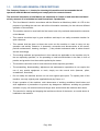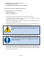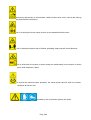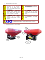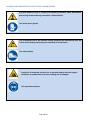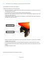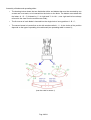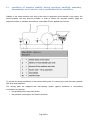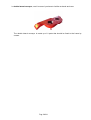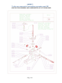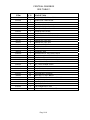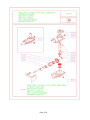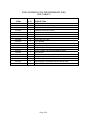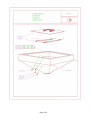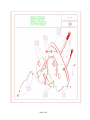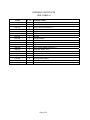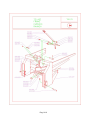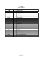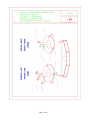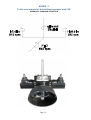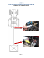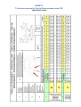
1
USER MANUAL referred to Double-disk fertilizer spreader model RE Issue n.1 dated 06/12/2010 Draft in accordance with the Directive on Machinery 2006 / 42 / CE by COSMO s.r.l. Costruzione di macchine agricole Via Laghi di Avigliana, 117 12022 Busca (CN) Pag. 1/54 CONTENTS 1.1.SCOPE AND GENERAL PRESCRIPTIONS 3 1.2. EC DECLARATION OF CONFORMITY 8 2. REFERENCES 9 3. DEFINITIONS 9 4. APPLICATION 10 5. RESPONSIBILITY 11 6. DESCRIPTION OF THE MACHINE 12 6.1 General description of the machine, and instructions and explanations necessary to understand how the machine operates 12 6.2 Machine drawings and diagrams necessary to understand its operation 17 6.3 Instructions for the machine commissioning and storage 19 6.4 Instructions for assembly, coupling and disassembly 21 6.5 Description and explanations necessary to operate and adjust the machine and to check its proper operation 30 6.6 description of workstations/areas that can be used by operators 39 6.7 description of adjustment and maintenance operations that must be carried out by the operator, as well as preventive maintenance and instructions to carry out adjustment and maintenance operations in safety conditions 41 6.8 warnings concerning the way to operate the machine and possible events that may occur, based on experience 43 6.9 conditions of machine stability during operation, handling, assembly, disassembly, out-ofservice, test or predictable failure conditions 44 6.10 instructions to carry out the transportation, handling and storage operations in safety conditions, indicating the machine and its element mass, in case they are transported separately 45 6.11 Operating mode to be complied with in case of failure or accident, in order to carry out any operation on the machine in safety conditions 48 6.12 notice on emission of noise and vibrations and instructions for installation and assembly aimed at reducing noise and vibrations 50 6.13 basic characteristics of accessories to be mounted on the machine 51 6.14 specifications of approved spare parts 54 Pag. 2/54 1.1. SCOPE AND GENERAL PRESCRIPTIONS The Company Cosmo s.r.l. thanks for choosing this machine and recommends that all operators read this Manual carefully and comply with the contents thereof. The technical information of this Manual are ownership of Cosmo srl and must be considered strictly reserved. It is forbidden text and illustration’s reproduction. • This User Manual is draft in accordance with the Directive on Machinery 2006 / 42 / CE for the purpose of providing the end user with all the information necessary for the safe and efficient operation of the machine. • The machine cannot be used until the final users have fully read and understood the contents of this Manual. This manual should be kept in good conditions and kept in an easily accessible location for • quick reference. This manual shall be given to those who must use the machine or need to carry out any • operation and activity related to it (assembly, connection and disconnection of the tractor, periodic maintenance, cleaning, transport ...); they should understand what is written therein and act accordingly. • The working methods and precautions in this manual are applicable to the machine only for the use expressly specified, i.e. the spreading of solid mineral fertilizer in the field, in form of powder and granules from the machine pulled by the tractor. • The machine cannot be used for uses other than those expressly provided. • The assembling, disassembling, adjustment and maintenance operations do not require the use of any special equipment or tools; simply use the normal tools (hammer, pliers, screwdrivers, wrenches). • Do not modify the machine and do not use non-original spare parts. To replace parts of the machine, use only original parts supplied directly by Cosmo s.r.l. • Proper operation of the machine, strict observance of working conditions listed below and strict application of precautions to prevent any dangerous situations, avoiding any possible accident or injury, will ensure better and longer work and minimize the machine down-times. The controls for starting and stopping the machine are those of the tractor; no control device is • installed on the machine. Pag. 3/54 The Company Cosmo s.r.l. is not liable in case of: • Disregard of prescriptions above • Non-application of instructions contained in this manual The machine is covered of a current warranty directive. The Company Cosmo s.r.l. considers a priority: • People safety and health • Protection of the environment • All the necessary solutions have been taken to ensure what is stated, namely: - The machine has all the necessary protective equipment to ensure the operator’s safety against the risks related to the machine operation, - The machine is designed to ensure compliance with the operator’s safety against the risk of physical, chemical and ergonomic nature. All operations described in this manual that can expose the operator to residual risks for his health and safety are marked with a warning about the presence of a risk: • This symbol, combined with words describing the same risk, is used in this manual to call attention to the safe and proper operation of the machine. Thus, it is necessary to comply with all prevention and protection measures associated to it: • This symbol, combined with words describing the same risk, is used in this manual to call attention on the obligation with which the operator shall comply. The machine is provided with stickers bearing the information on the risk, compulsory use of protective equipment, proper use of the machine: these labels should be kept always readable by regular cleaning and should be replaced if damaged. The meaning of safety signs applied to the machine is described below: • Pag. 4/54 before any intervention on the machine, switch off the tractor motor, remove the start-up key and read the instructions. risk of crushing due to the tractor motion: do not stand behind the tractor. risk of material projection due to fertilizer spreading: keep yourself at safe distance. risk of strike due to live parts in motion: keep your hands away from live parts in motion (drive shaft, distributor, disks). to ensure the machine proper operation, the tractor power take-off shall turn counterclockwise at 540 rev./min. mandatory use of protection gloves and shoes. Pag. 5/54 Safety signage on the machine • 2. ATTENTION! - RISK of gripping and dragging. Do not stay close to the moving parts. ATTENTION! Before any intervention on the machine, switch off the tractor motor, remove the start-up key and read the instructions. 1. ATTENTION! - RISK of crushing due to the tractor motion: do not stand behind the tractor. 4. ATTENTION! To ensure the machine proper operation, the tractor power take-off shall turn counter-clockwise at 540 RPM. 3. 6. ATTENTION! - Do not approach your arms/legs to the moving parts. 5. ATTENTION! - RISK of material projection due to fertilizer spreading: keep yourself at safe distance. 7. ATTENTION! Mandatory use of protection gloves and shoes. Decals positions as you can see above • 4 7 5 6 1-2-3 Pag. 6/54 To ensure environmental protection, only materials not containing hazardous substances have been used for the construction of the machine; it is equipped with devices and accessories that enable: To spread the exact amount of fertilizer required through accurate adjustment and distribution systems. It is essential to comply with prescriptions and instructions contained in this manual, in order to ensure the operator’s safety and health and the protection of the environment. In case of you do not understand the user manual do not hesitate to contact your seller or our factory to get any information concerning it. Our primary target is the satisfaction of the customer and that’s why we are glad to get any suggestions to improve the manual. Probably some machine details that you can see in the pictures are different compared to your machine, but this was indispensable to make the most possible clarity of the details. Pag. 7/54 1.2. EC DECLARATION OF CONFORMITY EC Declaration of Conformity According to the Directive on Machinery 2006 42 CE and following emendations The Company COSMO s.r.l., with head offices in Via Laghi di Avigliana 117, 12022 Busca (CN), Italy, manufacturer of machines for agriculture, declares, under its own responsibility, that the machine called: Double-disk fertilizer spreader model RE (800-1000) constructed in the year indicated in the machine identification plate, is in compliance with the requirements: • Directive 2006 42 CE and following emendations, and the requirements of the following EC Directives: • UNI EN ISO 13857/2008: safety distance, so that upper and lower limbs do not reach any dangerous area, • UNI EN ISO 4254-1/2006: safety of machines for agriculture, • EN 14017/2008: safety of solid fertilizer spreaders. • UNI EN 13739-1/2003 Machines for agriculture – Gravity and centrifugal spreaders for solid fertilizer – Protection of the environment – Requirements. This machine is designed to be connected to a tractor, in compliance with the requirements of the directive on machinery. Busca, 11/12/2009 The Manufacturer Pag. 8/54 2. REFERENCES • Directive on machinery 2006 / 42 / CE. (D. Lgs 17/2010). • Technical documents of the double-disk fertilizer spreader, model RE. • UNI EN ISO 4254-1 / June 2006: safety of machines for agriculture (part 1 : general requirements). • EN 14017 / December 2008: safety of solid fertilizer spreaders. • UNI EN 13739-1 Machines for agriculture – Gravity and centrifugal spreaders for solid fertilizer – Protection of the environment – Requirements. • UNI EN 13857 / may 2008: safety distance to avoid any contact between the arms/legs with dangerous zone. 3. DEFINITIONS For the purpose of annex I, point 1.1.1 of the Directive on Machinery 2006 / 42 / CE: A. ‘hazard’ means a potential source of injury or damage to health; B. ‘danger zone’ means any zone within and/or around machinery in which a person is subject to a risk to his health or safety; C. ‘exposed person’ means any person wholly or partially in a danger zone; D. ‘operator’ means the person or persons installing, operating, adjusting, maintaining, cleaning, repairing or moving machinery; E. ‘risk’ means a combination of the probability and the degree of an injury or damage to health that can arise in a hazardous situation; F. ‘guard’ means a part of the machinery used specifically to provide protection by means of a physical barrier; G. ‘protective device’ means a device (other than a guard) which reduces the risk, either alone or in conjunction with a guard; H. ‘intended use’ means the use of machinery in accordance with the information provided in the instructions for use; I. ‘reasonably foreseeable misuse’ means the use of machinery in a way not intended in the instructions for use, but which may result from readily predictable human behaviour. Pag. 9/54 4. APPLICATION This manual shall be applied to the following machine: • Name: double-disk fertilizer spreader. • Model: RE Type a: called RE 800 Type b: called RE 1000 • Size of the machine, when assembled (length x width x height): 130 x 150 x (100 - 110) cm Type a: height 100 cm Type b: height 110 cm • Weight when empty: Type a: weight when empty 180 kg Type b: weight when empty 190 kg • Capacity of fertilizer load: Type a: load capacity 800 kg Type b: load capacity 1000 kg • Weight at full load (i.e. weight when empty + fertilizer load capacity): Type a: weight at full load 980 kg Type b: weight at full load 1190 kg • Maximum spreading distance: 18 m • Driving: - through drive shaft connected to the power of the tractor (counter-clockwise and rotation speed 540 rpm) - Hydraulic with connection to the tractor system. • coupling system to the tractor, by 3 points. • Minimum requirements of the tractor: • - Power: 80 kw, - Lift load capacity: 1500 kg, Temperature interval of machine operation: - 5 ÷ +40 °C. Pag. 10/54 • On the machine are riveted the plate mentioning: - CE mark - model, - serial number, - year of construction. • Plate position on the machine 5. RESPONSIBILITY • Company’s name: COSMO s.r.l. • Business: manufacturing of machines for agriculture • Address: Via Laghi di Avigliana 117, 12022 Busca (CN), Italy • VAT no.: 01969400041. Pag. 11/54 6. DESCRIPTION OF THE MACHINE General description of the machine, and instructions and explanations necessary to understand how the machine operates 6.1 The fertilizer spreader with centrifugal distribution is a machine for agriculture that spreads in the field solid mineral fertilizer in granular and powder form. It is pulled by and coupled to the tractor by three points. The fertilizer spreader consists of: • A bearing chassis; • One hopper designed to contain the product to be spread; • Distribution components, driving and adjustment components. In the front side, the machine is equipped of a coupling structure with three coupling points to the tractor. The hopper in metal sheet has a truncated conical shape. Pag. 12/54 In its lower part is located the distribution unit, consisting of: • One stirrer, designed to shred any possible agglomerate of fertilizer; • One dispenser of the quantity of fertilizer to be used; • One distributor – spreader system, of double-disk type. Pag. 13/54 The fertilizer contained in the hopper goes through the dispenser and, due to gravity, falls on the distributor – spreader system. The dispenser is equipped with hydraulic control to open and close. The amplitude of the dispenser opening is manually, adjusted with a lever whose position is fixed on a knob. The distributor-spreader system consists of two horizontal disks with rotational motion; on their upper surface is a series of straight radial fins designed to distribute the product by means of centrifugal force. Pag. 14/54 The mobile part motion is given by the tractor: • Mechanically, through the power take-off and the driving shaft connected to the previous one, for the rotation of the stirrer and distributor-spreader; • Through an hydraulic system for the dispensing unit closing. Pag. 15/54 Safety devices are provided to avoid any contact with live parts in motion and to prevent any projection of material outside the working area, in detail: the agitator into the hopper is protected by a grid; • The protection grid is fixed to the frame by means of 4 cotter pins. The disassembly is necessary just for the replacement of the agitator or for the cleaning of the internal part of the hopper. • The driving system is protected by fixed protections; • The distribution rotary disks are protected by a fixed shaped bar; • In the front (tractor side) a fixed protection prevents any projection of material outside the working area. Pag. 16/54 Machine drawings and diagrams necessary to understand its operation 6.2 5 1 3 2 6 7 4 1. hopper 2. chassis and coupling points to the tractor 3. opening and distribution unit 4. rotary spreading disks and blades 5. opening grid (of the agitator into the hopper) 6. fixed rear protection (of spreading disks) 7. fixed front protection (protection towards the tractor driver) Pag. 17/54 All the machine accessible components: • Do not have sharp, wrinkled or pointed surface, • Are not made of materials hazardous for people health and the environment (metal materials, plastics, nylon, paints), • The component list and drawings are in annex 1 and 2; in detail, the following drawings are illustrated: - hopper - chassis and coupling and lifting points - main reduction gear - side reduction gear - opening and distribution unit - spreading disks and vanes. The accessible movable parts exposing the operator to the risk of being entangled, strike and projection of material (fertilizer) are protected as follows: • rotary spreading disks are equipped with fixed protections; • The agitator into the hopper is equipped with a protection. Such protection consists of a grid (as the fertilizer should go through it anyway) which is hinged to the hopper; • The drive shaft must be protected by means of telescopic tubes; in any working condition telescopic tubes must overlap at least 1/2 of their length in the position of maximum elongation, and overlap at least 1/3 of their length in any working condition. The machine is equipped with coupling points for the locking device used to prevent the rotation of the drive shaft protection; • The reduction gears, drive shafts and chains are equipped with fixed protections that can be disassembled with specific tools; • One front fixed protection is provided for the tractor driver against any fertilizer projection. Moreover: • The drawings and lists of components and spare parts are in annex 1; • The kinematic diagram from the tractor to the rotary disks is in annex 2; • The kinematic diagram from the tractor to the rotary disks is in annex 3; • The kinematic diagram from the tractor to the rotary disks is in annex 4; • Spreading tables, including parameters (type of fertilizer, spreading width, tractor speed…), are detailed in annex 5; • Assembly instructions are detailed in annex 6. Pag. 18/54 Instructions for the machine commissioning and storage 6.3 In transportation, storage and use of fertilizers, users must behave in accordance with the instructions contained in the product label and in particular the content of the risk phrases and safety advices. You need to lift the machine by means of a tractor with lifting capacity at least of 300 kg. The machine must be carried as follows: • empty the hopper • put tha machine on a pallet with capacity at least of 300 kg • fastening the machine to the pallet by means of straps • before lifting it check the fastening stability • lift the pallet by means of a tractor provided with forks and lifting capacity at least of 300 kg. It is not expected to carry the machine disassembled. Keep the machine in a preserved place from weather conditions in order to avoid any damages. Before to stop the machine for a long time you should do: • wash carefully the machine and the internal parts of the hopper (because the fertilizer is corrosive and that’s why can damage the machine); • make a general check of the machine to verify any possible damage and scraping of the paint. • verify that all decals are intact and in the original position otherwise you must replace them; • lubricate all automotive parts; • If is it possible keep the machine in a covered place. Pag. 19/54 HAZARDS AND PREVENTION AND PROTECTION MEASURES Cuts and abrasions due to contact and handling of blades, disks, distributors and driving elements during connection, disconnection. Use shear-proof gloves. Fall of material; fall of the machine during coupling and decoupling from the tractor and handling caused by the instability of the machine. Use safety shoes. Projection of materials and jets due to product loading into the hopper. Inhalation of powder due to product loading into the hopper Use protection glasses. Pag. 20/54 Instructions for assembly, coupling and disassembly 6.4 The assembling instructions are in annex 6. Connect the machine to the tractor as follows: • place the machine on a pallet about 20 cm high for easy coupling to the tractor (this will also help handling the unit itself); • go backwards with the tractor near the lower machine coupling points; • anchor the lower coupling points of the tractor to those of the machine through the pins and secure them with safety pins; • simply couple the upper coupling point of the machine to the third point of the tractor through the pin and secure with safety pins; hitch and upper pin hitch and lower pin • raise the machine a few centimetres and stop the lower lifting bars to prevent any potential oscillations during the work; • disconnect the power take-off and stop the engine and activate the parking brake of the tractor; • connect the drive shaft to the spreader reduction gear shaft and then to the power take-off of the tractor; • connect the hydraulic system. Disconnect the machine from the tractor as follows Pag. 21/54 • Place the machine on the ground (on a compact and levelled ground), checking the stability on the supporting points; place the machine on a pallet about 20 cm high for easy handling and following coupling to the tractor; • close the fertilizer outputs; • disconnect the power take-off; • switch the motor off and activate the parking brake of the tractor; • disconnect the hydraulic system; • disconnect the drive shaft from the tractor power take-off and then from the spreader reduction gear shaft; • disconnect the upper pin and the two lower pins of couplings and move the tractor forward. Pag. 22/54 Assembly of blades and spreading disks: • The drawing below shows the two distribution disks and blades that must be mounted by two screws and a nut each, to be inserted into the holes on the disks. The blades are marked with the letters A - B - C (followed by "r" for right and "l" for left -; note: right and left are always referred to the view from the machine rear side); • The first screw of each blade is inserted into the single hole of every position A - B - C; • The second screw is inserted into a slot with notches called 1 - 2 - 3; the choice of the position depends on the type of spreading to be achieved (see spreading table in annex 5); (see the code in annex 1) Pag. 23/54 Each spreading disk is connected to the machine driving motion by a support pin with fixing knob to be tightened by hand accurately. • Support pin Fixing knob The disassembly of the disks, operation necessary to allow thorough cleaning of the hopper, • should be carried out by reversing the assembly sequence or by unscrewing the fixing knob and removing the disks. Pag. 24/54 The driving motion is given from the tractor power take-off through the drive shaft, as follows: Before using the drive shaft, see the user and maintenance manual thereto. If the drive shaft supplied with the machine is not used, check that the machine and the tractor hoods overlap • the drive shaft protection at least for the rate provided by law. For proper operation of the machine use only shafts with CE marking; • Use only drive shafts with integral protections; • Grease periodically the drive shaft following the instructions supplied by the shaft manufacturer (see Use and Maintenance manual of the drive shaft); Comply with the drive shaft assembly direction, as specified by the manufacturer and shown • on the outer protection; • Hook the anti-rotation chains after making sure that the connection between the drive shaft and the reduction gear is perfect; • In case of you need to cut the PTO Shaft follow the indications of PTO Manual; • Hydraulic circuit: opening and closing of the fertilizer output from the hopper is achieved with an hydraulic device. There are two single-acting jacks placed under the hopper, which are controlled directly by the tractor. The spreader must be connected to the tractor with a high pressure pipe type R1T ¼" equipped with a rapid half-coupling suitable for the tractor. Therefore, it is essential that the hydraulics of the tractor is fitted with a single-acting auxiliary distributor. The hydraulic circuit diagram is in annex 3. Pag. 25/54 HAZARDS, PREVENTION AND PROTECTION MEASURES POWER TAKE-OFF: check that the rotation direction is counter-clockwise and the speed adjustment of the tractor power take-off is set to 540 rpm, as the machine is designed for this speed. Fall of material; fall of the machine during coupling and decoupling from the tractor and handling caused by the instability of the machine. Use safety shoes. Comply with instructions above. Cuts and abrasions due to contact and handling of blades, disks, distributors and driving elements during connection, disconnection. Use shear-proof gloves. Risk of tripping over and fall due to presence of obstacles on the ground and slippery floor. Use safety shoes. Pag. 26/54 Risk of being run down due to tractor movement and entrapment between the machine and the tractor. Compression and crushing due to the tractor lifting device motion. The connection between the tractor three points and the machine when the tractor is in operation must be carried out without people standing in the area between the tractor and the machine. Any maintenance, adjustment and cleaning operation must be carried out with the machine lowered to the ground (in stable conditions), the tractor engine off, power take-off disconnected, parking brake on, start-up key removed from the panel. Risk of being entangled due to presence of the drive shaft connecting the tractor – machine in operation. Use only cloths without parts that can be entangled. Any maintenance, adjustment and cleaning operation must be carried out with the machine lowered to the ground (in stable conditions), the tractor engine off, power take-off disconnected, parking brake on, start-up key removed from the panel. Muscle and bone injury due to product loading in the hopper and during machine coupling and decoupling. Materials heavier than 20 kg shall be lifted through specific devices or support of other people. Pag. 27/54 Shock due to presence of rotary spreading disks and their possible detachment due to incorrect assembly. Any maintenance, adjustment and cleaning operation must be carried out with the machine lowered to the ground (in stable conditions), the tractor engine off, power take-off disconnected, parking brake on, start-up key removed from the panel. The spreading disks must be assembled in accordance with instructions contained in point 6.4. Before start-up, check the proper spreading disk assembly. Shock due to hydraulic pipe disconnection. Projection of oil under pressure. Use anti-shear gloves. Periodically check the proper hydraulic pipe connection. Use protection goggles. Pag. 28/54 Impact due to obstacles present in the tractor and machine area. Caution: obstacles are present. Use safety shoes. Pag. 29/54 Description and explanations necessary to operate and adjust the machine and to check its proper operation 6.5 Before every start-up, check the following safety devices: • Guards of the drive shaft, • Guards of the hopper stirrer, • Fixed guards (of rotary disks, against projection of material towards the tractor, of the drive elements), Fixing knob of rotary spreading disks. • The manual loading of the hopper is carried out when the machine is lowered so that the height, measured from the top of the hopper to the ground or to any platform, does not exceed 1250 mm. The height of the machine is shown in the diagram in annex 4. Do not load the hopper over the edge to avoid the loss of fertilizer during the work and travel. Proper hopper filling: the fertilizer does not exceed the hopper edge. Improper hopper filling: the fertilizer exceeds the hopper edge. Any assembly mistake can be avoided by using only original parts provided by Cosmo s.r.l. (see annex 1) and by complying with the instructions contained in this manual. Pag. 30/54 Adjustment of fertilizer spreading: • Adjustment and total fertilizer output opening; the output control system is independent for each disk. There is a plate (Fig. A) on which there are two levers: one on the right and one the left. The levers are used to adjust the amount of fertilizer to be spread. After checking on the spreading chart (see Annex 5) the number to be adjusted, move the levers and lock them on the number indicating the desired amount. When the levers are as shown in picture A, the fertilizer output is wide open. Contrary, when the levers are as shown in picture B, the fertilizer output is closed. • Adjustment and fertilizer output opening only on one side (left or right): if the fertilizer must be spread only on one side, just set the levers so that only one of them makes the opening (fig. C). With the machine rear side in front of you, open the left levers to spread from the left-hand side and vice-versa. PIC. A PIC. B PIC. C Pag. 31/54 The spreading chart is in annex 5. Hydraulic opening group: The machine is provided with hydraulic cylinder that operate the opening of the distribution system. The hydraulic cylinder is “to simple effect” type (the distribution opening is due to the oil presence). • Dosage adjustment: • To make an adjustment of the dosage (fertilizer q.ty per hectare) there is a split system: the right spreading disc is provided with an adjustment system, separate from the left one. To obtain the adjustment of the dosage you have to move the adjusting slot lever for each disc. Each adjusting slot is provided with a measuring scale with 19 dosage positions. The 0 position means “shut” (pic. A below); to raise the spreading move gradually the lever toward the external side. The 18 position means “max”. The presence of two separate controls allow to spread in a different way on the right side and on the left one (pic. B below). To move the lever you have to screw the adjusting knob off, set the lever in a desired position and screw the knob again. PIC. A PIC. B PIC. C Pag. 32/54 Adjusting the spreading width: the spreader can be adjusted so that it can spread to different widths and with different types • of fertilizers. To make this possible you have to operate on the rpm of the PTO and on the vanes position. The machine is delivered and set to spread to 18 meters. • In order to achieve a good result, first run with the machine spreading only from one side, thus disabling one spreading disk. The spreading will be completed with further runs. • For the next steps you have to use the discs both; • If the spreading area remained is less than 18 meters you have to adjusting one disc in order to spread in a right way and do not spread in the closer area. Pag. 33/54 It is important care in regard to set up the right spreading width in order to avoid to trespass the spreading area, in so far you can find rivers, streets, other cultivations or habitations. Fill the hopper up and prepare the spreading as follows: • set the hydraulic opening lever in shut position; • switch the tractor engine off, disconnect the pto, set the handbrake on and remove the start-up key from the panel. • adjust the dosage by means of the levers by the discs; • adjust the spreading width changing the vanes position or size; • fill up the hopper with the fertilizer; • switch on the engine of the tractor and connect the pto; • set the hydraulic opening lever in working position (open). Pag. 34/54 Field distribution: • place the tractor at the beginning of the field (1). The distance from the border has to be the same of the spreading ray R; • move along the field perimeter keeping the R distance from the border as long as you arrive in the position 2. in this position you have to be at the R distance from the position 1; • go along till the position 3; • make a 180°-turn, place the tractor in position 4 a t the R distance from the position 3 and go along till the position 5; • do the same system as long as you have spread the all area of the field (positions 6 and 7). Spreading variables: • the quantity of fertilizer spread depends on the tractor speed, the spreading area, fertilizer type and humidity, weather conditions and from the adjusting machine; • keep the tractor speed constant for the all working time; • preserve the fertilizer in a way to keep unaltered its features. Pag. 35/54 HAZARDS, PREVENTION AND PROTECTION MEASURES Risk of fall from above and being run down due to presence of people on board the machines or within the working area. Use safety shoes. Do the loading with the machine in a bent down position. Fall of material during assembly, disassembly. Use safety shoes. Do the loading with the machine in a bent down position. Do not arrange the containeirs in unstable position. Cuts and abrasions due to contact and handling of blades, disks, distributors and driving elements during adjustment operations. Use shear-proof gloves. Pag. 36/54 Risk of tripping over and fall due to presence of obstacles on the ground and slippery floor. Use safety shoes. Risk of being run down due to tractor movement and entrapment between the machine and the tractor. Compression and crushing due to the tractor lifting device motion. Any adjustment operation must be carried out with the machine lowered to the ground (in stable conditions), the tractor engine off, power take-off disconnected, parking brake on, start-up key removed from the panel. Compression and crushing (being entangled) due to contact with the stirrer rotating inside the hopper. Any adjustment operation must be carried out with the tractor engine off, power take-off disconnected, parking brake on, start-up key removed from the panel. Check that the grid is closed. Pag. 37/54 Projection of materials and jets due to product loading into the hopper. Inhalation of powder due to product loading into the hopper. Use protection goggles. Use powder-proof mask. Muscle and bone injury due to product loading in the hopper and during machine coupling and decoupling. Materials heavier than 20 kg shall be lifted through specific devices or support of other people. Pag. 38/54 description of workstations/areas that can be used by operators 6.6 The workstation is the tractor driving station, where the following controls are available: • Tractor start-up, • Power take-off, • Hydraulic system. The machine is not equipped with stop and switch-off controls; the following fertilizer spreading adjustments are available: adjustment of fertilizer quantity to be spread. • The controls are of self-retained type (against uncontrolled or accidental movement). In case of unexpected power cut-off, the spreading stops without creating any type of hazard. The machine is designed to be used by only one operator who, during operation, has to remain in the control workstation on the tractor. The risk of projection exists within the spreading area, i.e. in the 18 m-radius half-circle behind the tractor. Pag. 39/54 HAZARDS, PREVENTION AND PROTECTION MEASURES Projection of materials and jets due to product spreading. Any intervention within the spreading area must be carried out with the tractor engine off, power take-off disconnected, start-up key removed from the panel. Check that the machine front guard is in place. All people within the spreading area must wear protection goggle. Risk of fall from above and being run down due to presence of people on board the machines or within the working area. Risk of being run down due to tractor movement and entrapment between the machine and the tractor. Check that no people are on board the machines or within the working area. Pag. 40/54 description of adjustment and maintenance operations that must be carried out by the operator, as well as preventive maintenance and instructions to carry out adjustment and maintenance operations in safety conditions 6.7 Any maintenance, adjustment and cleaning operation must be carried out with the machine lowered to the ground (in stable conditions), the tractor engine off, power take-off disconnected, parking brake on, start-up key removed from the panel. Before every use and after 8 hours of real operation, grease the driving unit. It is recommended to clean the greasing points from mud and other residual materials before injecting the grease. Grease points (shown below) using lubrication grease EP1. Lower view of opening plate. Pag. 41/54 HAZARDS, PREVENTION AND PROTECTION MEASURES Shock due to presence of rotary spreading disks. Any maintenance, adjustment and cleaning operation must be carried out with the machine lowered to the ground (in stable conditions), the tractor engine off, power take-off disconnected, parking brake on, start-up key removed from the panel. Cuts and abrasions due to contact and handling of blades, disks, distributors and driving elements during maintenance operations. Use shear-proof gloves. Compression and crushing (being entangled) due to contact with the stirrer rotating inside the hopper. Compression and crushing due to presence of motion distribution chains and pinions. Any adjustment operation must be carried out with the tractor engine off, power take-off disconnected, parking brake on, start-up key removed from the panel. Pag. 42/54 warnings concerning the way to operate the machine and possible events that may occur, based on experience 6.8 Never operate this machine if you are tired, sick or under the influence of medication, alcohol or other substance able to affect your attention and reflexes. Do not carry any passenger on board the tractor and the machine. The machine can be connected to a tractor with the following minimum requirements: • 80-kw power, • Load capacity of the lifting device of 1500 kg, The machine shall be connected to a tractor only by the 3 coupling points. During the work activities no person is allowed to stand within the spreading area. Before connecting the machine, ensure that this tractor is in good conditions and the brakes are working properly, especially when working on slopes. In case of failure, the operator must immediately stop the machine and check the problem and adopt any necessary measure. It is recommended to use the machine when the weather permits, as follows: • No rain and strong wind, • Ambient temperature range between - 5 ÷ +40 °C. Do not load the hopper over the edge to avoid the loss of fertilizer during the work and travel. Any assembly mistake can be avoided by using only original parts provided by Cosmo s.r.l. (see annex 1) and by complying with the instructions contained in this manual. Main inconvenients to avoid during fertilizer spreading: • spreading discs not in parallel with the ground; • different distribution parameters from the data indicated on the annex 5 or not kept constant during the working time; • distribution and spreading group damaged, fatigued or not properly cleaned; • wet fertilizer, not uniform or congealed. Pag. 43/54 conditions of machine stability during operation, handling, assembly, disassembly, out-of-service, test or predictable failure conditions 6.9 Stability of the tractor-machine unit: due to the mass of equipment and materials in the hopper, the tractor-spreader unit may become unstable. In order to ensure the complete stability, apply the expression below, to calculate the minimum front ballast Z to be applied to the tractor: To prevent any lateral oscillations of the machine during work it is necessary to lock the lower hydraulic lifter arms with stabilizers. The moving parts are equipped with self-retaining system (against accidental or uncontrolled movements) in particular: • the spreading discs have fixing knobs; • the hydraulic system pipes are fixed to the frame. Pag. 44/54 instructions to carry out the transportation, handling and storage operations in safety conditions, indicating the machine and its element mass, in case they are transported separately 6.10 In the transportation, storage and use of fertilizers, users must behave in accordance with the instructions contained in the product label and in particular the content of the risk phrases and safety advice. The machine is not designed to be transported broken down into its parts. Before any transportation of the machine, it is necessary to: • Disconnect the power take-off, • Completely empty the hopper, • Check that all parts are securely fixed. To lift the machine, use a lifting device with lifting capacity not lower than 300 Kg. The machine must be carried as follows: • empty the hopper • put it on a pallet with capacity at least of 300 kg • fastening the machine to the pallet by means of straps • before lifting the machine check the fastening stability • lift the pallet by means of a tractor provided with forks and lifting capacity at least of 300 kg. For any intervention of assembling, disassembling and replacement make sure to locate the machine on the ground and in a stability condition, with the power take off disconnected, the tractor engine switched off, the handbrake on and the start-up key removed from the panel. The assembling instructions are in the annex 6. To disassembling the machine follow the instructions in backward. Pag. 45/54 HAZARDS, PREVENTION AND PROTECTION MEASURES Cuts and abrasions due to contact and handling of blades, disks, distributors and driving elements during assembly, disassembly. Use shear-proof gloves. Fall of material during assembly, disassembly. Use safety shoes. Assembly the machine when lowered to the ground. Do not place materials in unstable position. Muscle and bone injury due to product machine handling. Materials heavier than 20 kg shall be lifted through specific devices or support of other people. Pag. 46/54 Fall of people from above, due to the operator’s position during assembly, disassembly. Use safety shoes. Carry out all operations when the machine is lowered. Risk of being entangled due to rotary drive shaft connecting the tractor – machine. Compression and crushing (entangling) due to contact wit the stirrer rotating inside the hopper. Compression and crushing due to presence of motion distribution chains and pinions. Any reset operation must be carried out with the tractor engine off, power take-off disconnected, parking brake on, start-up key removed from the panel. Pag. 47/54 Operating mode to be complied with in case of failure or accident, in order to carry out any operation on the machine in safety conditions 6.11 Any maintenance, adjustment and cleaning operation must be carried out with the machine lowered to the ground (in stable conditions), the tractor engine off, power take-off disconnected, parking brake on, start-up key removed from the panel. Machine start-up and stop controls are those of the pulling tractor; the machine is not equipped with controls. While removing solid parts of fertilizer, the machine must be disconnected from the tractor. For this operation, use the specific tools. In case of failure or improper operation, the operator must immediately stop the machine and check the problem and adopt any necessary measure. HAZARDS, PREVENTION AND PROTECTION MEASURES Risk of being entangled due to rotary drive shaft connecting the tractor – machine. Compression and crushing (being entangled) due to contact with the stirrer rotating inside the hopper. Compression and crushing due to presence of motion distribution chains and pinions. Any reset operation must be carried out with the tractor engine off, power take-off disconnected, parking brake on, start-up key removed from the panel. Pag. 48/54 Cuts and abrasions due to contact and handling of blades, disks, distributors and driving elements during reset operations. Use shear-proof gloves. Pag. 49/54 notice on emission of noise and vibrations and instructions for installation and assembly aimed at reducing noise and vibrations 6.12 The level of noise measured in the proximity of the workstation does not exceed 70 dB(A); therefore, the use of individual protection is not required while operating the machine. The machine does not generate any significant vibration. Pag. 50/54 basic characteristics of accessories to be mounted on the machine 6.13 The operating mode and precautions contained in this manual can be applied to the machine only for the intended and expressed use: spreading of granular fertilizer in the field by a machine pulled by a tractor. • Below is a list of accessories that can be used, together with a description of their assembly and operation. Any assembly and disassembly operation must be carried out with the machine lowered to the ground (in stable conditions), the tractor engine off, power take-off disconnected, parking brake on, start-up key removed from the panel. a. Rear signalling lamps; 2 position lights, direction indicators and -stop- signalling lamps to be mounted on the machine rear side through a bracket screwed in the frame holes. The lights should be connected to the tractor electric equipment. Before any road transportation, check the following: • Disconnect the power take-off, • Empty the hopper, • Check the correct coupling to the tractor in the 3 points, • Check that all the parts are fastened safely, • Mount the lights and signals required by the road regulations: - position lights, - direction indicators, - -stop- signalling lamps, - reflectors, - copy of the tractor registration plate. With reference to road circulation, note that: • it is prohibited to carry people on board the tractor or the machine, • it is prohibited to carry any material with the machine and pull any other vehicle, • it is mandatory to comply with the road regulations on agriculture tractors. Suggestions for proper use and maintenance of the lights: • before any use, check their proper operations • clean them after use. Pag. 51/54 b. double lateral conveyor; use it in case of you have to fertilize orchards and rows. The double lateral conveyor is made up of 2 parts that should be fixed to the frame by screws. Pag. 52/54 HAZARDS, PREVENTION AND PROTECTION MEASURES Crushing during the hopper cover opening and closing. Use shear-proof gloves. Periodically check the proper connection of pipes. Do not put your hands in the tarpaulin opening and closing device. Shock due to presence of rotary spreading disks. Any assembly, disassembly, maintenance and cleaning operation must be carried out with the machine lowered to the ground (in stable conditions), the tractor engine off, power take-off disconnected, parking brake on, start-up key removed from the panel. Cuts and abrasions due to contact and handling of blades, disks, distributors and driving elements during connection, disconnection. Use shear-proof gloves. Pag. 53/54 specifications of approved spare parts 6.14 For the machine spare parts (see annex 1), the Customer shall use only original parts and request them directly to Cosmo s.r.l. Any part replacement must be carried out with the machine lowered to the ground (in stable conditions), the tractor engine off, power take-off disconnected, parking brake on, start-up key removed from the panel. Pag. 54/54 ANNEX 1 To the user manual of the fertilizer spreader mod. RE COSTRUCTION DRAWINGS AND COMPONENTS LIST OF THE MACHINE: Pag. 1/12 CENTRAL GEARBOX SEE TABLE 1 ITEM 322.021 Q.TY 1 DESCRIPTION ASSEMBLED CENTRAL GEARBOX 323.028 1 UPPER SHAFT AGITATOR 326.003 5 KEY 8X7X20 309.001 2 OIL SEAL 35X52X7 310.002 6 BEARING 25X52X15 (6205) 306.007 1 GREASE NIPPLE M6 304.026 1 ALUMINIUM FLANGE 316.007 1 TOOTHED CROWN Z32 301.052 1 SELF-LOCKING NUT PN 5 25X1,5 316.005 2 PINION Z16 313.011 3 SPRING PIN 7435 E25 313.017 4 SPRING PIN 7437 I52 309.002 2 OUL SEAL 25X52X7 323.027 1 CENTRAL SHAFT 314.013 1 INTERNAL BOX 314.014 1 EXTERNAL BOX 300.200 300.201 1 1 SENSOR CAP OF OIL LEVEL 14X1.5 ALUMINIUM GASKET 14X18X1,5 323.002 1 INPUT SHAFT 303.052 4 FLAT WASHER 6292 10X20 ST.S 300.104 4 HEX. HEAD SCREW 10X30 UNI5739 ST.S 300.003 2 HEX. HEAD SCREW 10X25 301.053 2 SELF-LOCK. NUT M10 303.015 4 WASHER 10X20 300.040 12 SCREW 8X20 UNI5933 303.007 12 WASHER 8X17 UNI6592 301.001 12 HIGH SELF-L. NUT M8 ZB 300.026 2 HEX. HEAD SCREW 6X16 UNI5739 ZB 304.053 1 RUBBER RING 620.009 301.013 1 1 GASKET COVER RING HIGH SELF-L. NUT M10 619.033 619.034 1 1 PTB LOWER AGITATOR PTB LOWER AGITATOR PLATE Pag. 2/12 Pag. 3/12 SIDE GEARBOX FOR DISASSEMBLED DISK SEE TABLE 2 ITEM Q.TY DESCRIPTION 322.020 1 LATERAL GEARBOX RE 316.006 1 PINION Z19 310.001 2 BEARING 25X52X15 (6205 2RS) 310.002 1 BEARING 25X52X15 (6205) 329.011 1 SPACER 313.011 2 SPLIT RING 7435 E25 326.003 1 KEY 8X7X20 301.009 8 SELF-LOCK. NUT M6 304.002 1 DUST GUARD 306.010 1 GREASE NIPPLE 90° M8X1,25 300.026 8 HEX. HEAD SCREW 6X16 314.002 1 UPPER SHELL 323.023 1 OUTPUT SHAFT OF DISASSEMBLED DISK 326.004 1 KEY 6X6X20 316.004 1 PINION Z13 310.003 1 BEARING 20X52X15 (6304) 314.001 1 LOWER SHELL 300.014 6 GALVANIZED CYLINDRED HEAD SCREW 8X16 301.012 6 GALVANIZED NUT M8 Pag. 4/12 Pag. 5/12 HOPPER mod. RE SEE TABLE 3 ITEM Q.TY DESCRIPTION 609.061 1 HOPPER RE 800 609.060 1 HOPPER RE 1000 300.096 8 SCREW 10X25 ST.S 303.053 8 WASHER 10X30 ST.S 303.059 4 WASHER 12X36 ST.S 301.067 8 NUT M10 ST.S 304.052 2 RUBBER CAP DIAMETER: 14 MM 606.176 2 SUPPORT BAR INTO THE HOPPER 305.010 4 HAIR COTTER PIN FOR GRID 642.017 1 PROTECTION GRID Pag. 6/12 Pag. 7/12 OPENING UNIT/PLATE SEE TABLE 4 ITEM Q.TY DESCRIPTION 300.088 4 HEX. HEAD SCREW 8X25 ST.S 303.056 8 WASHER 8X16 ST.S 301.079 4 SELF-LOCK. NUT M8 ST.S 606.173 1 PLATE ST.S 606.172 2 LEVERS ST.S 606.175 1 OPENING DISC ST.S 606.174 1 SPACER 602.126 1 OPENING ROD 305.010 1 COTTER PIN R 332.004 1 OPENING ROD FORK 332.006 1 FORK CLIP 300.089 2 HEX. HEAD SCREW 10X25 ST.S 303.052 4 WASHER 10X20 ST.S 301.068 2 SELF-LOCK. NUT M10 ST.S 304.008 2 GRIP 25X5 302.002 2 KNOB 8X25 616.004 2 ADJUSTING INDEX 306.010 2 GREASE NIPPLE 90° 8X1,25 303.013 2 WASHER 8X24 Pag. 8/12 Pag. 9/12 FRAME SEE TABLE 5 ITEM Q.TY DESCRIPTION 620.129 1 FRAME RE 300.023 2 SCREW 10X20 303.008 4 WASHER 12X24 301.010 2 NUT M10 604.012 1 SHORT LEVER 329.010 1 NYLON SPACER 300.024 3 HEX. HEAD SCREW 12X35 UNI5739 303.047 4 WASHER 12X36 301.061 2 SELF-LOCK. NUT M12 616.004 300.097 1 1 INDEX SCREW 8X20 UNI5732 303.007 3 WASHER 8X17 302.005 1 KNOB 304.014 604.013 1 1 GRIP 30X10 LONG LEVER 300.029 2 HEX. HEAD SCREW 8X20 301.012 2 NUT M8 633.020 1 UPPER LIFTING PIN 25X144 302.007 2 CLICK PIN 633.022 2 LOWER LIFTING PIN 22-28 307.001 2 SPRING COTTER PIN 300.006 2 HEX. HEAD SCREW 12X60 303.008 2 WASHER 12X24 Pag. 10/12 Pag. 11/12 DISTRIBUTION DISKS SEE TABLE 6 ITEM Q.TY DESCRIPTION 610.060 1 ST.S. DISTRIBUTION DISK W/BUSH 610.061 1 ST.S. DISTRIBUTION DISK W/BUSH 610.062 1 ST.S. DISTRIBUTION DISK W/VANES 610.063 1 ST.S. DISTRIBUTION DISK W/VANES 300.107 12 SCREW 8X16 ST.S 301.064 12 NUT M8 ST.S 303.056 6 WASHER 8X16 ST.S 302.001 2 GROOVED HANDLE D.60 M10X20 601.040 1 LEFT ST.S VANE 601.042 2 LEFT ST.S BENT VANE 601.041 1 RIGHT ST.S VANE 601.043 2 RIGHT ST.S BENT VANE Pag. 12/12 ANNEX 2 To the user manual of the fertilizer spreader mod. RE KINEMATIC DIAGRAM OF MOTION Pag. 1/1 ANNEX 3 To the user manual of the fertilizer spreader mod. RE DIAGRAM OF THE HYDRAULIC CIRCUIT Pag. 1/1 ANNEX 5 To the user manual of the fertilizer spreader mod. RE SPREADING TABLE Pag. 1/1