1
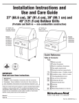
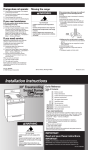
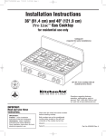
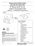
KAC-32
TECHNICAL EDUCATION
OUTDOOR
GAS GRILL
Models: KFGR270LSS, KFGR274LSS,
KFGR292LSS, KFGR364LSS,
KBGN274LSS, KBGN292LSS,
KBGN364LSS
JOB AID 4317333
FORWARD
This KitchenAid Job Aid, “Outdoor Gas Grill,” (Part No. 4317333), provides the technician with
information on the operation and service of the Outdoor Gas Grill. It is to be used as a training Job
Aid and Service Manual. For specific information on the model being serviced, refer to the “Use
and Care Guide” provided with the grill.
GOALS AND OBJECTIVES
The goal of this Job Aid is to provide detailed information that will enable the service technician to
properly diagnose malfunctions and repair the KitchenAid Outdoor Gas Grill.
The objectives of this Job Aid are to:
• Successfully perform necessary repairs.
• Successfully return the grill to its proper operational status.
WHIRLPOOL CORPORATION assumes no responsibility for any repairs made
on our products by anyone other than Authorized Service Technicians.
Copyright © 2003, Whirlpool Corporation, Benton Harbor, MI 49022
- ii -
TABLE OF CONTENTS
Page
GENERAL ............................................................................................................................... 1-1
Safety First ....................................................................................................................... 1-1
KitchenAid Model & Serial Number Designations ............................................................ 1-3
Model & Serial Number Label Location ........................................................................... 1-4
Specifications ................................................................................................................... 1-5
Warranty .......................................................................................................................... 1-8
INSTALLATION INFORMATION ........................................................................................... 2-1
Location Requirements .................................................................................................... 2-1
Important Safety Instructions ........................................................................................... 2-2
Product Dimensions ......................................................................................................... 2-4
Gas Supply Requirements ............................................................................................... 2-6
Rotisserie Electrical Requirements .................................................................................. 2-8
Converting To Natural Or L.P. Gas .................................................................................. 2-9
PRODUCT OPERATION ........................................................................................................ 3-1
Features ........................................................................................................................... 3-1
Lighting The Grill .............................................................................................................. 3-3
COMPONENT ACCESS ......................................................................................................... 4-1
Component Locations ...................................................................................................... 4-1
Removing The Control Panel, Spark Module, And Ignition Switch .................................. 4-2
Removing The Infrared Burner Ignitor & Thermocouple .................................................. 4-4
Removing The Infrared Burner ........................................................................................ 4-6
Removing A Burner, Burner Ignitor, Baso Gas Valve,
And Burner Gas Valve .................................................................................................. 4-8
Removing The Smoker Burner And Gas Valve ............................................................. 4-11
Removing The 9-Volt Battery ......................................................................................... 4-13
Removing A Cabinet Door ............................................................................................. 4-14
- iii -
— NOTES —
- iv -
GENERAL
SAFETY FIRST
Your safety and the safety of others is very important.
We have provided many important safety messages in this Job Aid and on the appliance.
Always read and obey all safety messages.
This is the safety alert symbol.
This symbol alerts you to hazards that can kill or hurt you and others.
All safety messages will follow the safety alert symbol and either the word
“DANGER” or “WARNING.” These words mean:
You can be killed or seriously injured if you don’t
immediately follow instructions.
WARNING
You can be killed or seriously injured if you don’t
follow instructions.
All safety messages will tell you what the potential hazard is, tell you how to reduce the
chance of injury, and tell you what can happen if the instructions are not followed.
WARNING
WARNING
Electrical Shock Hazard
Plug into a grounded 3-prong outlet.
Do not remove ground prong.
Do not use an adapter.
Do not use an extension cord.
Failure to follow these instructions can
result in death, fire, or electrical shock.
Explosion Hazard
Do not store fuel tank in a garage or
indoors.
Do not store grill with fuel tank in a
garage or indoors.
Failure to follow these instructions can
result in death, explosion, or fire.
1-1
WARNING
The California Safe Drinking Water and
Toxic Enforcement Act requires the Governor of California to publish a list of substances known to the State of California to
cause cancer, birth defects, or other reproductive harm, and requires businesses to
warn of potential exposure to such substances.
WARNING: This product contains a
chemical known to the State of California
to cause cancer, birth defects, or other
reproductive harm.
This appliance can cause low-level exposure to some of the substances listed, including benzene, crystalline silica, carbon
monoxide, toluene, and soot.
Burn Hazard
Do not remove the smoker box when
the grill is hot.
Doing so can result in burns.
1-2
KITCHENAID MODEL & SERIAL NUMBER DESIGNATIONS
MODEL NUMBER
MODEL NUMBER
INTERNATIONAL SALES IND.
OR MARKETING CHANNEL
IF PRESENT
K
FG
R
BRAND
KITCHENAID
PRODUCT IDENTIFICATION
FG = FREESTANDING GRILL
BG = BUILT-IN GRILL
MERCHANDISING SCHEME
R = L.P. GAS (CONVERTIBLE)
N = NATURAL GAS (CONVERTIBLE)
CAPACITY / SIZE / SERIES / CONFIGURATION
1ST POSITION
2 = 2 BURNERS / DIRECT COOKING
3 = 3 BURNERS / DIRECT & INDIRECT COOKING
4 = 4 BURNERS / DIRECT & INDIRECT COOKING
2ND POSITION
7 = 27″
6 = 36″
9 = 39″
8 = 48″
FEATURES
0 = BASE MODEL
2 = INTEGRATED ROTISSERIE & INTEGRATED SIDE BURNER
4 = INTEGRATED ROTISSERIE & FULL GRILLING SURFACE
YEAR OF INTRODUCTION
L = 2002
COLOR CODE
SS = STAINLESS STEEL
ENGINEERING CHANGE (NUMERIC)
SERIAL NUMBER
SERIAL NUMBER
X
L M
04
DIVISION RESPONSIBILITY
X = OXFORD, MS
MANUFACTURING SOURCE
L = LYNX
YEAR OF PRODUCTION
M = 2002, P = 2003
WEEK OF PRODUCTION
04 = 4th WEEK
PRODUCT SEQUENCE NUMBER
1-3
54321
27
4
L
SS
0
MODEL & SERIAL NUMBER LABEL LOCATION
The Model/Serial Number label location is shown below. NOTE: The label is located behind the
control panel. You must remove the smoker tray to read the label.
Model & Serial Number Location
(Located Behind The Control Panel)
1-4
SPECIFICATIONS
Model Number
Size
Description
Features
KFGR270LSS
27"
Portable (FS)
KFGR274LSS
27"
Portable (FS)
KFGR292LSS
39"
Portable (FS)
Stainless Steel / 2 piece grill rack - welded
3/8" rod. Bar grates. Grill rods are thick,
heavy and closely spaced
Stainless Steel / 2 piece grill rack - welded
3/8" rod. Bar grates. Grill rods are thick,
heavy and closely spaced
Stainless Steel / 2 piece grill rack - welded
3/8" rod. Bar grates. Grill rods are thick,
heavy and closely spaced
Storage cabinet
Yes - with divider in SS for preventing
storage of a second LP tank
Yes - with divider in SS for preventing
storage of a second LP tank
Yes - with divider in SS for preventing
storage of a second LP tank
SS Cart with locking wheels
Yes - 2 locking commercial type casters,
2 commercial type casters without lock
Yes - 2 locking commercial type casters,
2 commercial type casters without lock
Yes - 2 locking commercial type casters,
2 commercial type casters without lock
Burner cover - hood wrap
SS double wall design from front to
back- Sides single wall - Hood has side
brackets, one on each side, to hold hood
in place when open.
SS double wall design from front to
back- Sides single wall - Hood has side
brackets, one on each side, to hold hood
in place when open.
SS double wall design from front to
back- Sides single wall - Hood has side
brackets, one on each side, to hold hood
in place when open.
SS - KA Design - with insulator
on each end
SS - KA Design - with insulator
on each end
SS - KA Design - with insulator
on each end
Clean-out tray
Removable SS drip tray with "C"
guide and dimples/bumps
Removable SS drip tray with "C"
guide and dimples/bumps
Removable SS drip tray with "C"
guide and dimples/bumps
Fuel conversion
Yes, all units convertibles.
Yes, all units convertibles.
Yes, all units convertibles.
Fold down removable SS side shelves
Fold down removable SS side shelves
Fold down removable SS side shelves
Yes - Holding shelf inside the
cabinet doors, one on each door
Yes - Holding shelf inside the
cabinet doors, one on each door
Yes - Holding shelf inside the
cabinet doors, one on each door
2 SS Burners double U-shaped
22.5K BTU each burner
2 SS Burners double U-shaped
22.5K BTU each burner
2 SS Burners double U-shaped
22.5K BTU each burner
Yes, SS - Slope - Grease drains forward Long pins hold sear plates in place.
Yes, SS - Slope - Grease drains forward Long pins hold sear plates in place.
Yes, SS - Slope - Grease drains forward Long pins hold sear plates in place.
Infrared rotisserie back burner
No
SS -ceramic infrared burners- 14.5K BTU
infrared rotisserie back burners
SS -ceramic infrared burners- 14.5K BTU
infrared rotisserie back burners
Heavy Duty Rotisserie with Motor
and Spit (20 pounds turkey) Motor sealed - Cord and switch
approved for outdoor use.
No
Yes
Yes
Grates
Hood handle
Side preparation shelves
Storage Bin
Performance
Burners
V-shaped sear plates for
distributing heat
Smoker chamber/Burner - Smoker
drawer is a box in a box
Grilling surface area
Ignition
Dimensions/Specifications
Exterior Dimensions (grill opening)
Overall Length (in)
Overall Width (in)
Overall Height (in)
Cutout Dimensions
Cutout Height (in)
Cutout Width (in)
Cutout Length (in)
Net Weight (lbs)
Shipping Weight (lbs)
3000 BTU/HR gas-powered repositioned below burner
3000 BTU/HR gas-powered repositioned below burner
444 Sq. In.
444 Sq. In.
3000 BTU/HR gas-powered repositioned below burner
444 Sq. In.
Electric ignition - Battery operated Battery tray SS look.
Electric ignition - Battery operated Battery tray SS look.
Electric ignition - Battery operated Battery tray SS look.
27
26
48
27
26
48
39
26
49
NA
NA
NA
225
258
NA
NA
NA
225
258
NA
NA
NA
285
314
Miscellaneous
Warranty
Full
Limited
Yes
Yes
Yes
1 year
1 year
1 year
5 years
5 years
5 years
Lifetime
Lifetime
Lifetime
LP (convertible)
LP (convertible)
LP (convertible)
Kick toe plate around grill that
allows access to the locking wheels
Yes
Yes
Yes
LP tank
Yes
Yes
Yes
Stainless steel burners
Liquid Propane , Natural Gas
1-5
Model Number
Size
Description
Features
KFGR364LSS
36"
Portable (FS)
KBGN274LSS
27"
Built-In
Grates
Stainless Steel / 2 piece grill rack welded 3/8" rod. Bar grates. Grill rods
are thick, heavy and closely spaced
Stainless Steel / 2 piece grill rack - welded
3/8" rod. Bar grates. Grill rods are thick,
heavy and closely spaced
Storage cabinet
Yes - with divider in SS for preventing
storage of a second LP tank
No
Yes - 2 locking commercial type casters, 2
commercial type casters without lock
No
SS double wall design from front to
back- Sides single wall - Hood has side
brackets, one on each side, to hold hood
in place when open.
SS double wall design from front to
back- Sides single wall - Hood has side
brackets, one on each side, to hold hood
in place when open.
SS Cart with locking wheels
Burner cover - hood wrap
Hood handle
Clean-out tray
Fuel conversion
Side preparation shelves
Storage Bin
SS - KA Design - with insulator
on each end
Removable SS drip tray with "C"
guide and dimples/bumps
Yes, all units convertibles.
Fold down removable SS side shelves
Yes - Holding shelf inside the cabinet
doors, one on each door
SS - KA Design - with insulator on each end
Removable SS drip tray with "C"
guide and dimples/bumps
Yes, all units convertibles.
No
No
Performance
Burners
V-shaped sear plates for
distributing heat
Infrared rotisserie back burner
Heavy Duty Rotisserie with Motor
and Spit (20 pounds turkey) Motor sealed - Cord and switch
approved for outdoor use.
Smoker chamber/Burner Smoker drawer is a box in a box
Grilling surface area
Ignition
Dimensions/Specifications
Exterior Dimensions (grill opening)
Overall Length (in)
Overall Width (in)
Overall Height (in)
Cutout Dimensions
Cutout Height (in)
Cutout Width (in)
Cutout Length (in)
Net Weight (lbs)
Shipping Weight (lbs)
3 SS Burners double U-shaped
22.5K BTU each burner
2 SS Burners double U-shaped
22.5K BTU each burner
Yes, SS - Slope - Grease drains forward Long pins hold sear plates in place.
Yes, SS - Slope - Grease drains forward Long pins hold sear plates in place.
SS -ceramic infrared burners14.5K BTU infrared
rotisserie back burners
SS -ceramic infrared burners- 14.5K
BTU infrared rotisserie back burners
Yes
3000 BTU/HR gas-powered repositioned below burner
611 Sq. In.
Electric ignition - Battery operated Battery tray SS look.
Yes
3000 BTU/HR gas-powered repositioned below burner
444 Sq. In
Electric ignition - Battery operated Battery tray SS look.
36
26
48
27
26
24 5/8
NA
NA
NA
336
365
10 5/8
22 1/2
26 1/4
170
189
Warranty
Full
Limited
Stainless steel burners
Liquid Propane , Natural Gas
Yes
1 year
5 years
Lifetime
LP (convertible)
Yes
1 year
5 years
Lifetime
NG (Convertible)
Kick toe plate around grill that allows
access to the locking wheels
Yes
No
Yes
No
Miscellaneous
LP tank
1-6
Model Number
Size
Description
Features
Grates
Storage cabinet
SS Cart with locking wheels
Burner cover - hood wrap
Hood handle
KBGN292LSS
39"
Built-In
KBGN364LSS
36"
Built-In
Stainless Steel / 2 piece grill rack - welded
3/8" rod. Bar grates. Grill rods are thick,
heavy and closely spaced
Stainless Steel / 2 piece grill rack - welded
3/8" rod. Bar grates. Grill rods are thick,
heavy and closely spaced
No
No
No
No
SS double wall design from front to
back- Sides single wall - Hood has side
brackets one on each side, to hold hood
in place when open.
SS double wall design from front to backSides single wall - Hood has side brackets, one
on each side, to hold hood in place when open.
SS - KA Design - with insulator on each end
SS - KA Design - with insulator on each end
Clean-out tray
Removable SS drip tray with "C"
guide and dimples/bumps
Removable SS drip tray with "C"
guide and dimples/bumps
Fuel conversion
Yes, all units convertibles.
Yes, all units convertibles.
Side preparation shelves
No
No
Storage Bin
No
No
2 SS Burners double U-shaped
22.5K BTU each burner
3 SS double U-shaped
22.5K BTU burners
V-shaped sear plates for
distributing heat
Yes, SS - Slope - Grease drains forward Long pins hold sear plates in place.
Yes, SS - Slope - Grease drains forward Long pins hold sear plates in place.
Infrared rotisserie back burner
SS -ceramic infrared burners- 14.5K BTU
infrared rotisserie back burners
SS -ceramic infrared burners- 14.5K
BTU infrared rotisserie back burners
Yes
Yes
Performance
Burners
Heavy Duty Rotisserie with Motor
and Spit (20 pounds turkey) Motor sealed - Cord and switch
approved for outdoor use.
Smoker chamber/Burner - Smoker
drawer is a box in a box
Grilling surface area
Ignition
Dimensions/Specifications
Exterior Dimensions (grill opening)
Overall Length (in)
Overall Width (in)
Overall Heigth (in)
Cutout Dimensions
Cutout Height (in)
Cutout Width (in)
Cutout Length (in)
Net Weight (lbs)
Shipping Weight (lbs)
3000 BTU/HR gas-powered repositioned below burner
444 Sq. In.
Electric ignition - Battery operated Battery tray SS look.
3000 BTU/HR gas-powered repositioned below burner
610.5
Electric ignition - Battery operated Battery tray SS look.
39
26
24 5/8
36
26
24 5/8
10 5/8
22 1/2
38
190
213
10 5/8
22 1/2
35 1/4
230
248
Warranty
Full
Limited
Stainless steel burners
Liquid Propane , Natural Gas
Yes
1 year
5 years
Lifetime
NG (Convertible)
Yes
1 year
5 years
Lifetime
NG (Convertible)
Kick toe plate around grill that allows
access to the locking wheels
No
No
LP tank
No
No
Miscellaneous
1-7
WARRANTY
LENGTH OF WARRANTY
KITCHENAID WILL PAY FOR:
FULL ONE YEAR WARRANTY
From Date of Purchase
Replacement parts and repair labor to correct defects in materials or
workmanship. Service must be provided by a KitchenAid designated
service company.
LIMITED WARRANTY
2nd through 5th Year
Replacement parts for components if defective in materials or
workmanship.
LIFETIME WARRANTY
Replacement parts for the stainless steel burners for rust-through
resulting from defective materials or workmanship. Service must
be provided by a KitchenAid designated service company.
KITCHENAID WILL NOT PAY FOR:
A. Service calls to:
1. Correct the installation of the grill.
2. Instruct you how to use the grill.
3. Replace house fuses or correct house wiring or plumbing.
B. Repairs when grill is used in other than normal, single family household use.
C. Damage resulting from accident, alteration, misuse, abuse, fire, floods, acts of God, improper installation,
or installation not in accordance with local electrical and plumbing codes, or the use of products not
approved by KitchenAid or KitchenAid Canada.
D. Pickup and delivery. Your grill is designed to be repaired in the home.
E. Any labor costs during the limited warranty period.
F. Replacement parts or repair labor costs for units operated outside the United States and Canada.
G. Repairs to parts or systems caused by unauthorized modifications made to the grill.
KITCHENAID AND KITCHENAID CANADA DO NOT ASSUME ANY RESPONSIBILITY FOR INCIDENTAL OR CONSEQUENTIAL DAMAGES.
Some states do not allow the exclusion or limitation of incidental or consequential damages, so this
exclusion or limitation may not apply to you. This warranty gives you specific legal rights and you may
also have other rights which may vary from state-to-state, or province-to-province.
Outside the United States and Canada, this warranty does not apply. Contact your authorized
KitchenAid dealer to determine if another warranty applies.
If you need service, first see the “Troubleshooting” section in the Use and Care Guide. Additional help
can be found by checking the “Assistance or Service” section, or by calling our Customer Interaction
Center at: 1-800-422-1230, from anywhere in the U.S.A., and 1-800-807-6777, from anywhere in
Canada.
1-8
INSTALLATION INFORMATION
LOCATION REQUIREMENTS
Select a location that provides minimum exposure to wind and traffic paths. The location
should be away from strong draft areas.
Do not obstruct flow of combustion and ventilation air.
WARNING
WARNING
Explosion Hazard
Do not store fuel tank in a garage or
indoors.
Do not store grill with fuel tank in a
garage or indoors.
Failure to follow these instructions can
result in death, explosion, or fire.
Fire Hazard
Do not install this grill on or near
combustible materials.
Doing so can result in death or fire.
WARNING
If you plan to use a combustible enclosure,
return this grill, and replace it with the model
that is manufactured for use in a combustible
enclosure.
Clearance to combustible construction for
built-in (non-combustible construction) and
portable grills
A minimum of 12″ (30.5 cm) must be maintained between the grill hood, sides and back
and any combustible construction. A 12″ (30.5
cm) minimum clearance must also be maintained below the cooking surface and any
combustible construction.
Rotisserie
If your model is equipped with a rotisserie, 6″
(15.2 cm) minimum clearance on each end is
needed for the motor and skewer.
A grounded, 3-prong outlet located to the left of
the grill is required (see “Rotisserie Electrical
Requirements” on page 2-8).
Fire Hazard
Do not use grill near combustible
materials.
Do not store combustible materials
near grill.
Doing so can result in death or fire.
2-1
IMPORTANT SAFETY INSTRUCTIONS
8.
Inspect the gas cylinder supply hose before each use of the grill. If the hose shows
excessive abrasion or wear, or is cut, it
MUST be replaced before using the grill.
Contact your dealer and use only replacement hoses specified for use with the grill.
9. Visually check the burner flames. They
should be blue. Slight yellow tipping is
normal for L.P. gas.
10. Check and clean burner/venturi tube for
insects and insect nest. A clogged tube
can lead to fire under the grill.
11. The L.P. gas supply cylinder to be used
must be:
• Constructed and marked in accordance
with the Specification for L.P. Gas Cylinders of the U.S. Department of Transportation (DOT) or the National Standard of Canada, CAN/CSA-B339, Cylinders, Spheres, and Tubes for Transportation of Dangerous Goods, and
Commission.
• Provided with a listed overfilling prevention device.
• Provided with a cylinder connection device compatible with the connection for
outdoor grill appliances.
FOR YOUR SAFETY
If you smell gas:
1. Shut off gas to the appliance.
2. Extinguish any open flame.
3. Open lid.
4. If odor continues, immediately call
your gas supplier or your fire
department.
FOR YOUR SAFETY
1. Do not store or use gasoline or other
flammable vapors and liquids in the
vicinity of this or any other appliance.
2. An L.P. cylinder not connected for
use shall not be stored in the vicinity
of this or any other appliance.
1.
2.
3.
4.
5.
6.
7.
Do not install portable or built-in grills in or
on a recreational vehicle, portable trailer,
boat or in any other moving installation.
Always maintain minimum clearances from
combustible construction, see “Location
requirements” section.
The outdoor cooking gas appliance shall
not be located under overhead combustible construction.
This outdoor cooking gas appliance shall
be used only outdoors and shall not be
used in a building, garage, or any other
enclosed area.
Keep any electrical supply cord and fuel
supply hose away from any heated surfaces.
Keep outdoor cooking and appliance area
clear and free from combustible materials,
gasoline and other flammable vapors and
liquids.
Do not obstruct the flow of combustion and
ventilation air. Keep the ventilation openings of the cylinder enclosure free and
clear from debris.
12. Always check connections for leaks each
time you connect and disconnect the L.P.
gas supply cylinder.
13. When the outdoor cooking gas appliance
is not in use, the gas must be turned off at
the supply cylinder.
14. Storage of an outdoor gas grill appliance
indoors is permissible only if the cylinder is
disconnected and removed from the outdoor gas grill.
15. Cylinders must be stored outdoors and
out of the reach of children and must not
be stored in a building, garage, or any
other enclosed area.
2-2
IMPORTANT: This grill is manufactured for
outdoor use only.
For grills that are to be used at elevations
above 2000 feet, orifice conversion is required (see “Gas Supply Requirements”
on page 2-6).
It is the responsibility of the installer to comply
with the minimum installation clearances specified on the model/serial rating plate. The model/
serial rating plate can be found on the heat
shield behind control panel, close to smoker
box.
16. The pressure regulator and hose assembly supplied with the outdoor gas grill must
be used. Replacement pressure regulator
and hose assembly part number listed in
the “lnstallation Instructions.”
17. The cylinder supply system must be arranged for proper vapor withdrawal.
18. Gas cylinder must include a collar to protect the cylinder valve.
WARNING: If the information in this
manual is not followed exactly, a fire
causing death or serious injury may
occur.
Copies of the standards listed may be obtained
from:
National Fire Protection Association
One Batterymarch Park
Quincy, Massachusetts 02269
If the following information is not followed
exactly, a fire causing death or serious injury
may occur.
• Do not store a spare L.P. gas cylinder
under or near this grill.
• Never fill the cylinder beyond 80 percent
full.
CSA International
8501 East Pleasant Valley Rd.
Cleveland, Ohio 44131-5575
2-3
PRODUCT DIMENSIONS
PORTABLE & BUILT-IN MODELS
A minimum of 12″ (30.5 cm) must be maintained between the grill hood, sides and back,
and any combustible construction. A 12″ (30.5
cm) minimum clearance must also be maintained below the cooking surface and any
combustible construction.
Clearance to combustible construction for
built-in (non-combustible construction) and
portable grills:
12″
(30.5 cm)
27″ (68.6 cm)
OR
36″ (91.4 cm)
12″
(30.5 cm)
Side Tray*
Side Tray*
* Not All Models Have Side Trays
26″
(66.0 cm)
25-1/2″
(64.8 cm)
23″
(58.4 cm)
11-1/8″
(28.3 cm)
34″
(86.4 cm)
24-5/8″
(62.5 cm)
36″
(91.4 cm)
Portable
Models
1/2″
Male NPT
Locking Front
Casters
2-4
3-5/8″
(9.2 cm)
BUILT-IN INSTALLATION
(NON-COMBUSTIBLE ENCLOSURE)
WARNING
Enclosure and clearance dimensions that
are shown must be used. Given dimensions
provide required clearances.
The installation of this grill must conform with
the current standards CSA-Z21.58a-1998*, or
with local codes.
For installations in a non-combustible enclosure, the grill drops into the opening and is
supported by its side flanges. Do not use a
bottom support.
Fire Hazard
Do not install this grill on or near
combustible materials.
Doing so can result in death or fire.
Copies of the standards listed may be obtained
from:
* CSA International
8501 East Pleasant Valley Rd.
Cleveland, Ohio 44131-5575
12″ (30.5 cm)
Minimum To
Any Accessory
A
2-1/4″
(5.7 cm)
22″
(57.2 cm)
6″ (15.2 cm)
Minimum Clearance
For Rotisserie
Gas Line
Location At
Rear Of Grill
7-3/8″
(18.7 cm)
2″ (5.1 cm)
Minimum To
Open Hood
35-1/2″
(90.2 cm)
10-7/8″
(27.0 cm)
B
Optional Custom
Access Doors
1-1/8″
(2.9 cm)
19″
(48.3 cm)
Counter or Support Surfaces
Must Be Level
Non-Combustible Enclosure Installations
Grill Size
27″ (68.6 cm)
36″ (91.4 cm)
2-5
A
26″ (66.7 cm)
35″ (89.5 cm)
B
25-1/4″ (64.1 cm)
34-1/4″ (87.0 cm)
GAS SUPPLY REQUIREMENTS
Observe all governing codes and ordinances. IMPORTANT: Grill must be connected to a regulated gas supply.
• Input ratings shown on the model/serial rating plate are for elevations up to
2,000 feet (610 m). For elevations
above 2,000 feet (610 m), ratings are
reduced at a rate of 4% for each 1,000
feet (305 m) above sea level. Orifice
conversion is required.
• Refer to the model/serial rating plate for
information on the type of gas that can
be used. If this information does not
agree with the type of gas available,
check with your local gas supplier.
PORTABLE GRILLS
L.P. Gas
This grill is equipped for use with an L.P. gas
fuel tank. It is design-certified by CSA International for local L.P. gas supply, or for Natural
gas with appropriate conversion.
L.P. Gas From A Local L.P. Gas Supply
IMPORTANT: The gas installation must conform with local codes, or in the absence of local
codes, with the National Fuel Gas Code, ANSI
Z223.1/NFPA 54. The qualified L.P. gas technician shall provide the L.P. gas supply to the
selected grill location in accordance with the
National Fuel Gas Code, NFPA 54, and local
codes.
No attempt shall be made to convert the
grill from the gas specified on the model/
serial rating plate for use with a different gas type without consulting the serving gas supplier. The conversion kits
specified must be used.
Natural Gas Conversion
Conversion must be made by a qualified
gas technician. The qualified natural gas technician shall provide the natural gas supply to
the selected grill location in accordance with
the National Fuel Gas Code NFPA 54, and
local codes. For conversion to Natural gas, the
Natural gas conversion kit must be used.
IMPORTANT: The gas installation must conform with local codes, or in the absence of local
codes, with the National Fuel Gas Code, ANSI
Z223.1/NFPA 54.
To convert to Natural gas, the Natural Gas
Conversion Kit #4396311 must be used. Instructions are included with the kit.
L.P. Gas:
Operating pressure: 11 inches (27.9 cm)
W.C.
Supply pressure: 11 to 14 inches (27.9 to
35.5 cm) W.C.
LINE PRESSURE TESTING
Testing Above 1/2 psi (3.5 kPa) Or
14 Inches (35.5 cm) W.C. (Gauge)
The grill and its individual shutoff valve must be
disconnected from the gas supply piping system during any pressure testing of that system
at test pressures greater than 1/2 psig
(3.5 kPa).
Testing Below 1/2 psi (3.5 kPa) Or
14 Inches (35.5 cm) W.C. (Gauge) Or Lower
The grill must be isolated from the gas supply
piping system by closing its individual manual
shutoff valve during any pressure testing of the
gas supply piping system at test pressures
equal to or less than 1/2 psig (3.5 kPa).
Natural Gas:
Set pressure: 4 inches (10.2 cm) W.C.
Supply pressure: 7-14 inches (17.8 cm to
35.5 cm) W.C. maximum.
2-6
BUILT-IN GRILLS (NONCOMBUSTIBLE CONSTRUCTION)
L.P. Gas Conversion From
A Local L.P. Gas Supply
Conversion must be made by a qualified
gas technician. The qualified natural gas technician shall provide the L.P. gas supply to the
selected grill location in accordance with the
National Fuel Gas Code NFPA 54, and local
codes. To convert to L.P. gas, the L.P. Gas
Conversion Kit #4396312 must be used. Follow the instructions included with the kit.
Natural Gas:
Built-in grill models are equipped for use with
Natural gas. They are design-certified by CSA
International for L.P. (propane or butane) gases
with appropriate conversion.
Built-in models are set for natural gas use and
have a pressure regulator with 1/2″ female
pipe threads.
The supply line shall be equipped with an
approved shutoff valve. This valve should be
located in the same area as the grill and should
be in a location that allows ease of opening and
closing. Do not block access to the shutoff
valve. The valve is for turning on or shutting off
gas to the appliance.
L.P. Gas Conversion Using
An L.P. Fuel Tank
To convert to L.P. gas, the L.P. Gas Conversion Kit #4396312 must be used. Follow the
instructions included with the kit.
An L.P. gas cylinder, not larger than 20 pounds,
must be purchased separately.
Natural Gas:
Set pressure: 4 inches (10.2 cm) W.C.
Supply pressure: 7-14 inches (17.8 cm to
35.5 cm) W.C. maximum.
Shutoff Valve
“Open” Position
To Grill
L.P. Gas:
Operating pressure: 11 inches (27.9 cm)
W.C.
Supply pressure: 11 to 14 inches (27.9 to
35.5 cm) W.C.
Gas Supply
Line
2-7
ROTISSERIE ELECTRICAL REQUIREMENTS
Recommended Ground Method
A grounded 3-prong outdoor outlet grounded
in accordance with the National Electrical Code
ANSI/NFPA 70**, or Canadian Electrical Code
(C22.1*)—and local codes and ordinances.
WARNING
3-Prong Polarized GroundType Outdoor Outlet
Electrical Shock Hazard
Plug into a grounded 3-prong outlet.
Do not remove ground prong.
Do not use an adapter.
Do not use an extension cord.
Failure to follow these instructions can
result in death, fire, or electrical shock.
3-Prong
Ground Plug
Power
Supply Cord
Ground
Prong
Copies of the standards listed above may be
obtained from:
If codes permit and a separate ground wire
is used, it is recommended that a qualified
electrician determine that the ground path
is adequate.
Check with a qualified electrician if you are
not sure whether the grill is properly
grounded.
Do not ground to a gas pipe.
A 120-volt, 60 Hz, AC-only, 15-ampere, electrical supply is required.
* CSA International
8501 East Pleasant Valley Rd.
Cleveland, Ohio 44131-5575
** National Fire Protection Association
One Batterymarch Park
Quincy, Massachusetts 02269
2-8
CONVERTING TO NATURAL OR L.P. GAS
NATURAL GAS ORIFICES
Gas conversion must be done by a qualified
installer.
The Natural Gas Conversion Kit orifices are as
follows:
(2) #50 (Infrared Burners)
(4) #44 (Grill Burners)
(2) #66 (Smoker Burners)
(1) Convertible Regulator Assembly
(4″ Natural & 10″ L.P.)
WARNING
CONVERTING THE GRILL
Fire Hazard
Shut off gas supply line valve.
Make all conversions before turning
gas supply valve back on.
Failure to follow these instructions
could result in explosion, fire or other
injury.
To convert the grill for use with either Natural or
L.P. gas, perform the following steps.
1.
2.
The gas grill can be converted for use with
either natural or L.P. (Liquid Petroleum) gas.
To convert the grill, you will have to change the
orifices at the following locations:
Turn off and disconnect the gas supply
going to the grill.
To convert the infrared burner:
a) Remove the screw from the rear access panel and remove the panel.
Rear Access Panel
(1) Infrared Burner
(3) Main Burners
(1) Smoker Burner
Screw
In addition to changing the orifices, you will
have to install the correct gas pressure regulator. There is a separate regulator assembly for
use with each type of gas.
L.P. GAS ORIFICES
The L.P. Conversion Kit orifices are as follows:
(2) #57 (Infrared Burners)
(4) #55 (Grill Burners)
(2) #77 (Smoker Burners)
(1) Brass Elbow 3/8″ Flare Fitting To 1/2″
NPT
(1) L.P. Hose & Regulator Assembly
Continued on the next page.
2-9
b) Remove the infrared burner orifice and
replace it with the proper conversion
orifice (#50/NAT or #57/L.P.).
4.
To convert the smoker burner:
a) Remove the grill burners from the grill
(see step 2 on page 4-8 for the procedure).
b) Remove the two screws from the
smoker burner bracket.
Smoker Burner
In Bracket Slot
Infrared Burner Orifice
3.
Smoker Ports
Facing Up
To convert the grill burners:
a) Remove the grill burners from the grill
(see step 2 on page 4-8 for the procedure).
b) Use a 1/2″ deep socket, and remove
the grill burner gas valve orifices. Replace the orifices with the proper conversion orifices (#44/NAT or #55/L.P.).
Smoker Burner
Bracket & Screws
Front View From
Burner Box
Grill Orifice
c) Pull the smoker burner off the gas valve
orifice.
d) Use a 1/2″ deep socket, and remove
the orifice from the smoker burner gas
line. Replace the orifice with the proper
conversion orifice (#66/NAT or #77/L.P.).
Grill Burner Gas Valve
Orifice
Smoker Burner Orifice
Grill Gas Valve Shown With Front Panel Removed
2-10
Smoker Burner
5.
To replace the gas regulator:
a) Remove the four screws from the rear
panel and remove the panel.
Screw (1 of 4)
Rear Panel
b) Disconnect the regulator from the gas
supply.
e) For L.P. To Natural Gas Only:
- Remove the brass elbow from the
manifold.
- Connect the natural gas regulator to
the manifold. Use a pipe thread sealant that is certified for use with Natural gas.
f) For Natural To L.P. Gas Only:
- Mount the brass elbow from the kit to
the manifold. Use a pipe thread sealant that is certified for use with L.P.
gas.
- Connect the L.P. gas regulator to the
brass elbow on the end of the manifold. Use a pipe thread sealant that
is certified for use with L.P. gas.
Brass Elbow
(L.P. Gas Only)
Manifold
Regulator Connector
c) Disconnect the regulator hose from the
brass elbow (if installed) on the grill
manifold.
d) Remove the screw from the hose clamp
and remove the clamp from the hose.
Regulator Hose Clamp W/Screw
Continued on the next page.
2-11
GAS HOOKUP & LEAK CHECK
1.
2.
3.
4.
For Natural Gas: Connect a certified 1/2″
gas supply pipe to the inlet side of the
regulator from a natural gas supply, according to local codes requirements. Use
a pipe thread sealant that is certified for
use with natural gas at connections, where
required.
For L.P. Gas: Connect the regulator hose
connector to a full 20# L.P. tank, and
hand-tighten it.
Turn on the gas supply to the grill.
Test all of the connections by brushing on
an approved noncorrosive leak-detection
solution. Bubbles will indicate a leak. Correct any leaks found.
ADJUSTING THE AIR SHUTTERS
1.
2.
3.
4.
5.
Light the grill using information in “Lighting
The Grill” on page 3-3.
Observe the flame to determine which
burners need adjustment, and how the
flame is acting.
Turn off the valve and wait until the grill
and burners are cool.
Remove the grill grates and sear plates.
Remove the burner and loosen the air
shutter adjustment screw.
a) If the flame is yellow (not enough air),
turn the air shutter counterclockwise.
b) If the flame is noisy, or lifts away from
the burner (too much air), turn the air
shutter clockwise.
Adjustment should be from 1/8″ to 1/4″.
7.
8.
9.
LOW FLAME ADJUSTMENT
If the flame goes out on the “LO” setting, the low
flame setting must be adjusted.
1. Turn off the valve and wait until the grill
and burners are cool.
2. Remove the grill grates and sear plates.
3. Light the grill using the information in “Lighting The Grill” on page 3-3.
4. Turn the burner to its lowest setting and
remove the knob.
5. Hold the valve stem with pliers and insert
a thin flat-blade screwdriver into the shaft.
Valve Stem
6.
Watch the flame and slowly turn the screwdriver counterclockwise.
7. Adjust the flame to a minimum stable
flame.
8. Replace the control knob and turn off the
burner.
9. Repeat Steps 3 through 8 for each burner,
if needed.
10. Replace the sear plates and grates after
the burners have cooled.
Air Shutter Screw
6.
Replace the burner sear plates and grates.
Ignite the burners and check the flames.
Repeat Steps 1 through 8, if needed. Only
adjust the burners that need adjustment.
Tighten the air shutter adjustment screw.
2-12
FINAL ASSEMBLY
1.
2.
3.
4.
Allow the burners to cool.
Replace the burner cover, sear plates,
grates, smoker tray, and access cover.
The grill nameplate is located behind the
front panel. Remove the knobs and the
screws that hold on the front panel to
locate the nameplate. For a Natural Gas
Conversion, check the box next to “Natural Gas” or the box next to “LP Gas” for L.P.
Conversion.
5.
2-13
In the last page of the owners manual,
write the type of conversion you performed.
Also record the conversion date and the
technician/company that performed the
conversion.
On the grill is a red label where you should
also mark the type of conversion you performed.
— NOTES —
2-14
PRODUCT OPERATION
FEATURES
Infrared (IR)
Burner
Fold-Away Shelf
Ignition Switch
Removable
Grease Tray
9-Volt Battery
Compartment
Smoker Tray
Large Storage
Area
Heavy Duty
Locking Casters
Typical Carted Model Shown
Not All Features Are Available On All Models
3-1
Direct Or Indirect Cooking—Sear food directly over the heat source, or indirectly cook
the food by utilizing reflected heat. As the heat
rises, it reflects off the lid and the inside surfaces, and slowly cooks the food evenly on all
sides.
Stainless Steel Construction—The outdoor
grill is constructed of welded stainless steel.
Carted Or Built-In Models—The grill is fully
assembled for immediate use, and is available
in portable, or built-in models. Portable models
are supplied with a 20 lb. L.P. tank. Built-in
models are set up for use with natural gas. All
models are easily converted for use with natural or L.P. gas.
Smoke Flavoring—Every grill features a gas
powered smoker drawer. Use mesquite,
hickory, black walnut, or orange chips to create
a variety of flavor enhancements.
Evenness Of Cooking—Specially-designed
stainless steel sear plates assist with heat
distribution throughout the grill, to minimize
flare-ups, and eliminate hot spots. Stainless
steel main burners, each rated at 22,500 BTUs,
allow for just the right amount of heat for
exceptional cooking.
Rotisserie Cooking—Prepare perfect roast
chicken and tenderloin slowly and evenly with
the Stainless Steel & Ceramic Infrared Burner.
Ignition System—The ignition system is powered by a 9-volt battery and solid state ignition
module.
Insect Guards—The main burners are provided with insect guards (screen) over the air
shutters that prevent insects from blocking the
burners.
3-2
LIGHTING THE GRILL
PREPARE THE GAS SUPPLY
1.
2.
IMPORTANT: Light only one burner at a time.
1. Do not lean over the burners. Push in and
turn to “LITE” the control knob for the
burner you wish to use.
2. Push in the burner ignitor button. You will
hear the “snapping” sound of the spark.
Keep the burner ignitor button pushed in
until the burner lights. Make sure the burner
is lit. Repeat for each of the other burners,
as needed.
IMPORTANT: If the burner does not light immediately, turn the burner knob to “OFF,” and
wait 5 minutes before relighting.
Open the hood completely. Do not light the
burners with the hood closed.
Make sure that the control knobs are OFF.
The grease tray must be in place and
pushed all the way to the back.
Grease Tray
MANUALLY LIGHTING
THE GRILL BURNERS
3.
Turn the gas supply on.
• For portable grills using an L.P./ propane gas cylinder, slowly open the cylinder valve; do not “snap” open.
NOTE: If the flow limiting device does
activate, the grill may not light. If the grill
does light, the flames will be low, and will
not heat properly. Turn the cylinder valve
and all control knobs OFF, and wait 30
seconds. After shutting off the cylinder,
very slowly open the cylinder valve, and
wait 5 seconds before lighting.
• For grills using a gas supply source
other than an L.P. gas cylinder, turn the
shutoff valve to the “open” position from
the front of gas supply line.
1.
Remove the manual lighting extension
from inside the grease tray.
2.
3.
4.
Attach a match to the clip.
Strike the match to light it.
Carefully guide the lit match between the
grill grate and one of the slots in the sear
plate.
5.
Push in and turn the burner knob to “LITE”
for the burner closest to the lit match. The
burner will light immediately.
Repeat steps 2 through 5 for each main
burner.
Replace the manual lighting extension
inside the grease tray.
LIGHTING THE GRILL BURNERS
Red Button
Grill Burner Knob
Smoker Tray
Burner Ignitor Button
6.
IR Burner Knob
Smoker Burner Knob
Grill Burner Knob
7.
Battery Compartment
Continued on the next page.
3-3
IMPORTANT: If the burner does not light immediately, turn the burner knob to “OFF” and
wait 5 minutes before relighting.
If any burners do not light after attempting to
manually light them, contact the KitchenAid
Assistance Center.
2.
3.
4.
Attach a match to the clip.
Strike the match to light it.
Carefully hold the lit match close to the
infrared burner.
5.
Push in and turn the infrared burner control knob to”LITE”.
LIGHTING THE INFRARED (IR)
ROTISSERIE BURNER
1.
Push in and turn the rotisserie burner knob
to “LlTE.”
2. At the same time, push in both the red
button, (left hand side), and the burner
igniter button (right hand side). You will
hear a “snapping” sound.
3. When the infrared burner lights, release
the burner igniter button, but continue
pressing the red button for another 5 to 10
seconds.
IMPORTANT: If the rotisserie burner does not
light immediately, turn the burner knob to “OFF,”
and wait 5 minutes before relighting.
6.
Push in the red button above the infrared
burner control knob. The burner will light
immediately. Hold this button in for 5 to 10
seconds.
7. Repeat steps 3 through 6 for each infrared
burner (the number of infrared burners
varies by model).
8. Replace the manual lighting extension
inside the drip tray.
IMPORTANT: If the infrared burner does not
light immediately, turn the infrared burner control knob to “OFF,” and wait 5 minutes before
relighting.
MANUALLY LIGHTING THE
INFRARED (IR) ROTISSERIE
BURNER
1.
Remove the manual lighting extension
from inside the grease tray.
3-4
MANUALLY LIGHTING THE
SMOKER BURNER
5.
Carefully guide the lit match into the smoker
chamber area where the tray was removed.
WARNING
Burn Hazard
Do not remove the smoker box when
the grill is hot.
Doing so can result in burns.
1.
2.
Remove the smoker tray.
Remove the manual lighting extension
from inside the grease tray.
3.
4.
Attach a match to the clip.
Strike the match to light it.
6.
Push in and turn the knob for the smoker
burner to “LITE.” The burner will light immediately.
7. Replace the smoker tray.
8. Repeat steps 1 through 6 for each smoker
burner (the number of smoker burners
varies by model).
9. Replace the manual lighting extension
inside the grease tray.
IMPORTANT: If the smoker burner does not
light immediately, turn the burner knob to “OFF,”
and wait 5 minutes before relighting.
Always allow the box to cool before removing
or cleaning it.
3-5
— NOTES —
3-6
COMPONENT ACCESS
This section instructs you on how to service each component inside the Outdoor Gas Grill. The grill
components and their locations are shown below.
COMPONENT LOCATIONS (TYPICAL)
Infrared Burner Ignitor &
Thermocouple
Infrared Burner
Smoker Burner
Baso Gas
Valve
Spark Module
Burner
Smoker Burner
Gas Line Connector
Smoker Burner
Gas Valve
Burner Ignitor
Burner Gas Valve
4-1
9-Volt Battery
Ignition Switch
REMOVING THE CONTROL PANEL,
SPARK MODULE, AND IGNITION SWITCH
1.
2.
5.
Turn off and disconnect the gas supply
going to the grill.
Pull the knobs off the gas valves.
Smoker Tray
Knobs & Bezels
To remove the control panel:
a) If you are replacing the control panel,
not just removing it, remove the two
screws from each of the bezels and
remove the bezels.
Bezel Screw
(1 of 2)
Grease Tray
3.
Ignition Switch
Pull out and remove the smoker tray.
b) Remove the two bottom outside screws
from the control panel, then lower the
control panel and tip it forward. Provide
a padded surface to avoid damage to
the finished surface, and rest the panel
on the support.
Smoker Tray
4.
Pull out and remove the grease tray.
Grease
Tray
Control Panel
Screw (1 of 2)
Spark Module
4-2
Spark Module Screws
Control Panel
6.
To remove a spark module:
a) Loosen (do not remove) the two spark
module screws (see the photo in step
5b on page 4-2).
b) Remove the cover from the spark module.
c) Remove the strip of insulation.
7.
To remove the ignition switch:
a) Remove the bezel nut from the control
panel and remove the switch.
Spark Module Cover
Bezel Nut
Insulation Strip
Ignition Switch
b) Disconnect the two wires from the terminals.
d) Disconnect the wires and battery connector from the terminals. NOTE: The
wire connectors are different sizes to
prevent miswiring. The two larger wire
connectors are for the ignition switch,
and the smaller wire connectors are for
the ignitors. The ignitor connectors may
be connected to any of the smaller
terminals.
Battery Connector
Ignition Switch
Ignitor Wires (4)
2 Ignition Switch Wires
4-3
Wires
REMOVING THE INFRARED BURNER IGNITOR
& THERMOCOUPLE
1.
Turn off and disconnect the gas supply
going to the grill.
c) Remove the screws from the rear panel
and remove the panel.
Infrared Burner Ignitor & Thermocouple
Screw (1 of 4)
Rear Panel
d) Remove the screw from the infrared
burner ignitor & thermocouple cover
and remove the cover.
2.
To remove the infrared burner ignitor:
a) Remove the control panel and the spark
module (see pages 4-2 and 4-3 for the
procedures).
b) Disconnect the infrared burner ignitor
wire from the spark module terminal
and cut the wire tie holding it to the
manifold.
Cut Wire Tie
Infrared Burner Ignitor Wire
IR Burner Ignitor & Thermocouple Cover Screw
e) Remove the screw from the infrared
burner ignitor bracket and remove the
ignitor from the unit.
IR Burner Ignitor Screw
4-4
3.
To remove the thermocouple:
a) Remove the control panel (see page
4-2 for the procedure).
b) Unscrew the thermocouple connector
from the baso gas valve.
Baso Gas Valve
c) Remove the rear panel and the infrared
burner ignitor & thermocouple cover
(see steps 2c and 2d on page 4-4).
d) Push the thermocouple out of its holding clip.
e) Pull the sensor tube through the two
access holes at the rear of the unit, and
remove the thermocouple.
Thermocouple Connector
Thermocouple & Clip
Access Holes
4-5
REMOVING THE INFRARED BURNER
1.
2.
3.
Turn off and disconnect the gas supply
going to the grill.
Remove the infrared burner ignitor from
the grill (see step 2 on page 4-4 for the
procedure).
Disconnect the top 5/8″ gas line fitting
going to the infrared burner.
4.
Remove the screw from the rear access
panel and remove the panel.
Rear Access Panel
Screw
Disconnect Gas
Line Here
Rear Of Unit
5.
Disconnect the gas line fitting from the
infrared burner.
Infrared Burner
Gas Line Fitting
Rear Of Unit
4-6
6.
Push the thermocouple out of its holding
clip and position it in the access opening.
7.
8.
Thermocouple Out Of Clip
Remove the burner grates and griddle, if
installed.
Remove the three screws from the front of
the infrared burner panel, then pull the
front of the panel forward, and remove the
burner panel from the unit.
Infrared Burner Panel
Access Opening
3 Panel Screws
REASSEMBLY NOTE: Turn on the gas to the
grill, and test all of the connections by brushing
on an approved noncorrosive leak-detection
solution. Bubbles will indicate a leak. Correct
any leaks found.
4-7
REMOVING A BURNER, BURNER IGNITOR,
BASO GAS VALVE, AND BURNER GAS VALVE
1.
2.
Turn off and disconnect the gas supply
going to the grill.
To remove a burner:
a) Remove the grates, the griddle (if installed), and the sear plates.
b) Lift the rear of the burner, pull the air
shutter off the gas valve orifice, and
remove the burner.
Grates
Sear Plates
Burner
Air Shutter With
Insect Guard
4-8
3.
To remove a burner ignitor:
a) Remove the grates, the griddle (if installed), and the sear plates.
b) Remove the control panel and the spark
module (see pages 4-2 and 4-3 for the
procedures).
c) Remove the two 5/8″ hex nuts from the
front cover, pull the top of the cover
forward, and remove it.
d) Remove the screw from the ignitor
bracket and collector box. NOTE: Hold
the collector box while removing the
screw since the screw secures both the
ignitor and the collector box.
Collector Box
5/8″ Nuts
Bracket &
Collector
Box Screw
Front Cover
Bracket &
Collector Box
Screw
Burner Ignitor
e) Disconnect the burner ignitor wire connector from the spark module.
Ignitor Wires
Continued on the next page.
4-9
4.
To remove the baso gas valve:
a) Remove the control panel (see page
4-2 for the procedure).
b) Remove the thermocouple and gas line
connectors from the baso gas valve.
c) Unscrew the baso gas valve from the
manifold and remove it. NOTE: The two
valves are replaced as an assembly.
5.
Gas Line & Thermocouple Connectors
Baso Gas Valve
To remove a burner gas valve:
a) Remove the control panel (see page
4-2 for the procedure).
b) Remove the two 5/8″ hex nuts from the
front cover and remove the cover (see
step 3c on page 4-9).
c) Remove the burner air shutter from the
gas valve orifice (see step 2b on page
4-8 for the procedure).
d) Unscrew the burner gas valve from the
manifold and remove the valve.
REASSEMBLY NOTES:
• When you replace a gas valve, use an
appropriate thread sealant that is approved
for use with L.P. gas.
• Turn on the gas to the grill, and test all of the
connections by brushing on an approved
noncorrosive leak-detection solution.
Bubbles will indicate a leak. Correct any
leaks found.
Burner Gas Valve
Manifold
REASSEMBLY NOTES:
• When you replace a gas valve, use an
appropriate thread sealant that is approved
for use with L.P. gas.
• Turn on the gas to the grill, and test all of the
connections by brushing on an approved
noncorrosive leak-detection solution.
Bubbles will indicate a leak. Correct any
leaks found.
4-10
Manifold
REMOVING THE SMOKER BURNER AND GAS VALVE
c) Remove the two screws from the rear
burner rail and move the rail to the rear
of the burner box.
WARNING
Screw
Screw
Rear Burner Rail
Burn Hazard
Do not remove the smoker box when
the grill is hot.
Doing so can result in burns.
1.
2.
Turn off and disconnect the gas supply
going to the grill.
To remove the smoker burner:
a) Remove the grates, the griddle (if installed), the sear plates, and the burners from the grill (see page 4-8).
b) Remove the two screws from the burner
bracket and remove the bracket from
the end of the smoker burner.
d) Pull the smoker burner off the gas valve
orifice.
e) To remove the smoker burner orifice,
unscrew it from the gas valve.
Smoker Burner Orifice
Smoker Burner
Smoker Burner
In Bracket Slot
Continued on the next page.
Smoker Ports
Facing Up
Smoker Burner
Bracket & Screws
(1 of 2)
4-11
f) Remove the slotted end of the smoker
burner from the opening in the rear
burner rail.
c) Remove the flex gas line connector
from the smoker burner gas valve.
d) Unscrew the smoker burner gas valve
from the manifold.
Smoker Burner
Gas Valve
Slotted End Of Smoker Burner
Manifold
Flex Gas Line Connector
REASSEMBLY NOTE: Make sure to position
the smoker burner with the ports facing up
when you reinstall it in the bracket.
e) To replace the flex line between the
smoker burner gas valve and the
smoker burner, disconnect the line from
the 90° elbow at the burner.
Smoker Burner
90° Elbow
Smoker Burner
In Bracket Slot
Smoker Ports
Facing Up
3 . To remove the smoker burner gas valve:
a) Remove the control panel (see page
4-2 for the procedure).
b) Remove the front cover (see step 3c on
page 4-9 for the procedure).
Flex Gas Line Connector
REASSEMBLY NOTES:
• When you replace a gas valve, use an
appropriate thread sealant that is approved
for use with L.P. gas.
• Turn on the gas to the grill, and test all of the
connections by brushing on an approved
noncorrosive leak-detection solution.
Bubbles will indicate a leak. Correct any
leaks found.
4-12
REMOVING THE 9-VOLT BATTERY
1.
To remove the 9-volt battery:
a) Pull the battery holder cover out at the
bottom to release the magnetic seal.
b) Pull the battery holder out of the control
panel.
c) Remove the battery from the holder
and unclip the connector from the battery terminals.
Battery Holder Cover
Battery & Connector
4-13
REMOVING A CABINET DOOR
1.
2.
To remove the cabinet door, open the
door.
Lift the door straight up, and unhook the
hinge pins from the hinge hangers.
Lift Door
Straight Up
4-14
PRODUCT SPECIFICATIONS
AND
WARRANTY INFORMATION SOURCES
IN THE UNITED STATES:
FOR PRODUCT SPECIFICATIONS AND WARRANTY INFORMATION CALL:
FOR WHIRLPOOL PRODUCTS: 1-800-253-1301
FOR KITCHENAID PRODUCTS: 1-800-422-1230
FOR ROPER PRODUCTS:
1-800-447-6737
FOR TECHNICAL ASSISTANCE WHILE AT THE CUSTOMER’S HOME CALL:
THE TECHNICAL ASSISTANCE LINE: 1-800-253-2870
HAVE YOUR STORE NUMBER READY TO IDENTIFY YOU AS AN
AUTHORIZED SERVICER
FOR LITERATURE ORDERS:
PHONE: 1-800-851-4605
IN CANADA:
FOR PRODUCT SPECIFICATIONS AND WARRANTY INFORMATION CALL:
1-800-461-5681
FOR TECHNICAL ASSISTANCE WHILE AT THE CUSTOMER’S HOME CALL:
THE TECHNICAL ASSISTANCE LINE: 1-800-488-4791
HAVE YOUR STORE NUMBER READY TO IDENTIFY YOU AS AN
AUTHORIZED SERVICER