1
Setting the Standard With the
World's Most Valued Grinders.
ACCU-Pro
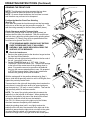
MODEL 670
SEMI-AUTOMATIC
BEDKNIFE GRINDER
This book consists of two manuals:
The OPERATORS MANUAL which contains all the
information on operating and doing routine daily
maintenance on this equipment.
The ASSEMBLY and SERVICE MANUAL which is
used by the maintainence department to install the
equipment and to do all maintenance except routine
daily maintenance.
1
2
ACCU-Pro
MODEL 670
SEMI-AUTOMATIC
BEDKNIFE GRINDER
OPERATORS
MANUAL
WARNING
You must thoroughly read and understand this manual
before operating the equipment, paying particular attention
to the Warning & Safety instructions.
3
6707953 (3-98)
SAFETY INSTRUCTIONS
Safety Awareness Symbols are inserted into this
manual to alert you to possible Safety Hazards.
Whenever you see these symbols, follow their
instructions.
The Warning Symbol identifies special instructions
or procedures which, if not correctly followed, could
result in personal injury.
The Caution Symbol identifies special instructions
or procedures which, if not strictly observed, could
result in damage to or destruction of equipment.
1. KEEP GUARDS IN PLACE and in working
order.
12. DON'T OVERREACH. Keep proper footing and
balance at all times.
2. REMOVE WRENCHES AND OTHER TOOLS.
13. MAINTAIN GRINDER WITH CARE.
Follow
instructions in the Assembly and Service Manual
for lubrication and preventive maintenance.
3. KEEP WORK AREA CLEAN.
4. DON'T USE IN DANGEROUS ENVIRONMENT.
Don't use Grinder in damp or wet locations, or
expose it to rain. Keep work area well lighted.
5. KEEP ALL VISITORS AWAY. All visitors
should be kept a safe distance from work area.
6. MAKE WORK AREA CHILD-PROOF with
padlocks or master switches.
14. DISCONNECT POWER BEFORE SERVICING.
15. REDUCE THE RISK OF UNINTENTIONAL
STARTING. Make sure all switches are OFF
before plugging in the Grinder.
16. USE RECOMMENDED ACCESSORIES. Consult
the manual for recommended accessories. Using
improper accessories may cause risk of personal
injury.
7. DON'T FORCE THE GRINDER. It will do the job
17. CHECK DAMAGED PARTS. A guard or other
better and safer if used as specified in this
part that is damaged or will not perform its intended
manual.
function should be properly repaired or replaced.
8. USE THE RIGHT TOOL. Don't force the Grinder
18. KNOW YOUR EQUIPMENT. Read this manual
or an attachment to do a job for which it was not
carefully. Learn its application and limitations as
designed.
well as specific potential hazards.
9. WEAR PROPER APPAREL. Wear no loose
19. KEEP ALL SAFETY DECALS CLEAN AND
clothing, gloves, neckties, or jewelry which may
LEGIBLE. If safety decals become damaged or
get caught in moving parts. Nonslip footwear is
illegible for any reason, replace immediately. Refer
recommended. Wear protective hair covering to
to replacement parts illustrations in Service Manual
contain long hair.
for the proper location and part numbers of safety
decals.
10. ALWAYS USE SAFETY GLASSES.
20. DO NOT OPERATE THE GRINDER WHEN UNDER
11. SECURE YOUR WORK. Make certain that the
THE INFLUENCE OF DRUGS, ALCOHOL, OR
bedbar and bedknife is securely fastened with the
MEDICATION.
electromagnets provided before operating.
4
SAFETY INSTRUCTIONS
IMPROPER USE OF GRINDING WHEEL MAY CAUSE
BREAKAGE AND SERIOUS INJURY.
Grinding is a safe operation if the few basic rules listed below are followed.
These rules are based on material contained in the ANSI B7.1 Safety Code for
"Use, Care and Protection of Abrasive Wheels". For your safety, we suggest
you benefit from the experience of others and carefully follow these rules.
DON'T
DO
1. DON'T use a cracked wheel or one that
HAS BEEN DROPPED or has become
damaged.
1. DO always HANDLE AND STORE wheels in
a CAREFUL manner.
2. DO VISUALLY INSPECT all wheels before
mounting for possible damage.
2. DON'T FORCE a wheel onto the machine
OR ALTER the size of the mounting hole.
If wheel won't fit the machine, get one that
will.
3. DO CHECK MACHINE SPEED against the
established maximum safe operating speed
marked on wheel.
3. DON'T ever EXCEED MAXIMUM
OPERATING SPEED established for the
wheel.
4. DO CHECK MOUNTING FLANGES for equal
and correct diameter.
5. DO USE MOUNTING BLOTTERS when
supplied with wheels.
4. DON'T use mounting flanges on which the
bearing surfaces ARE NOT CLEAN, FLAT
AND FREE OF BURNS.
6. DO be sure WORK REST is properly
adjusted.
5. DON'T TIGHTEN the mounting nut
EXCESSIVELY.
7. DO always USE A SAFETY GUARD
COVERING at least one-half of the grinding
wheel.
6. DON'T grind on the SIDE OF THE
WHEEL (see Safety Code B7.2 for
exception).
8. DO allow NEWLY MOUNTED WHEELS to
run at operating speed, with guard in place,
for at least one minute before grinding.
7. DON'T start the machine until the WHEEL
GUARD IS IN PLACE.
8. DON'T JAM work into the wheel.
9. DO always WEAR SAFETY GLASSES or
some type of eye protection when grinding.
9. DON'T STAND DIRECTLY IN FRONT of a
grinding wheel whenever a grinder is
started.
10. DO TURN OFF COOLANT before stopping
to avoid creating an out-of-balance condition.
10. DON'T FORCE GRINDING so that motor
slows noticeably or work gets hot.
AVOID INHALATION OF DUST generated by grinding and cutting operations.
Exposure to dust may cause respiratory ailments. Use approved NIOSH or
MSHA respirators, safety glasses or face shields, and protective clothing.
Provide adequate ventilation to eliminate dust, or to maintain dust level
below the Threshold Limit Value for nuisance dust as classified by OSHA.
5
Setting the Standard With the World's Most Valued Grinders.
We ar
e committed to:
are
Providing superior customer support, training,
and service.
Manufacturing the highest quality products at an
unequaled value.
Setting the industry standard by investing in
technological product innovation.
Manufacturing products specifically designed to
maintain original equipment manufacturers'
specifications.
Interacting with and supporting all original
equipment manufacturers.
6
This machine is intended for grinding the bedknife from a reel type
mowing unit ONLY. Any use other than this may cause personal injury and void
the warranty.
To assure the quality and safety of your machine and to maintain the
warranty, you MUST use original equipment manufactures replacement
parts and have any repair work done by a qualified professional.
ALL operators of this equipment must be thoroughly trained BEFORE
operating the equipment.
Do not use compressed air to clean grinding dust from the machine. This
dust can cause personal injury as well as damage to the grinder. Machine is for
indoor use only. Do not powerwash machine.
Low Voltage Relay
The grinder is equipped with a low voltage relay which is factory preset at 100
VAC. If the power supply line does not deliver 100 VAC power under load, the
relay will open and trip out the starter. If this occurs, your power supply line is
inadequate and must be correct before proceeding further with the grinder.
ADJUSTMENT OF THE LOW VOLTAGE RELAY MAY CAUSE
ELECTRICAL COMPONENT FAILURE. ADJUSTMENT OF THE LOW
VOLTAGE RELAY WILL VOID ALL ELECTRICAL COMPONENT
WARRANTY.
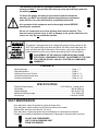
CONTENTS
Safety Warnings ........................................................................................... Page 3 - 7
Daily Maintenance ........................................................................................ Page 6
Getting to Know your Grinder ....................................................................... Page 8 - 11
General Operating Instructions .................................................................... Page 12 - 17
Operating Instructions .................................................................................. Page 18 - 25
SPECIFICATIONS
Electrical Requirements ...................................................... 115V 50/60 Hz, 15-amp circuit
Net Weight ................................................................................................. 780 lbs [354 kg]
Shipping Weight ......................................................................................... 920 lbs [417 kg]
Maximum Grinding Length ......................................................................... 34 in. [863 mm]
Sound Level ................................................................................................Less than 75 Dba
DAILY MAINTENANCE
On a daily basis, clean the grinder by wiping all areas down.
On a daily basis, check coolant tray fluid level and filter sock content.
Replace filter sock when full (about 6" [15 cm"]).
On a daily basis, inspect the grinder for loose fasteners or components and tighten.
Contact your company's Maintenance Department if damaged or defective parts are found.
DO NOT USE COMPRESSED
AIR TO CLEAN GRINDING DUST
FROM THE GRINDER.
7
OPERATING INSTRUCTIONS
PLEASE TAKE SPECIAL NOTE OF THE FOLLOWING WARNING DECALS
LOCATED ON THE ACCU-PRO BEDKNIFE GRINDER.
Symbols to "Read
operators manual", "wear
safety glasses" and
"disconnect power before
servicing".
Symbol for keep visitors
a safe distance away
from grinder and the
symbol for sharp object
which will cause serious
injury.
Symbol for hot surface
which could cause
burns.
Symbol identifying a
panel, cover, or area as
having live electrical
components within.
Symbol for caution relating to RPM
of the motor and minimum safe
rated RPM of the grinding wheel.
--WARNING-FOR YOUR OWN SAFETY READ
ASSEMBLY AND OPERATING MANUAL
BEFORE OPERATING.
1. Always use safety glasses and ear protection.
2. Do not wear gloves, neckties, loose clothing,
etc.
3. This machine operates with a large amount of
hot sparks. Do not operate near flammables.
4. Stay clear of grinding wheel contact area when
grinding. Always stay clear of all rotating and
moving parts.
5. Insure adequate dust control before operation.
6. Only properly trained personnel should operate
the machine. Keep all visitors a safe distance
from the machine.
7. Be certain that the cutting unit is securely
fastened with the clamps and handles provided
before operating.
8. Do not ever exceed maximum operating speed
marked on the grinding wheel. (Read grinding
wheel safety section in your manual before grinding).
9. Disconnect your machine from the main power
source before performing any adjustments,
mechanical servicing or electrical servicing.
10. When machine is in automatic cycle, do not
leave the work area without turning off power.
11. Keep all guards in place and in good repair.
12. Before operating, inspect the machine for loose
damaged, or missing parts. If found, repair or
replace. Remove all tools from operating area.
8
SEE PAGE 3
FOR GRINDING
WHEEL SAFETY.
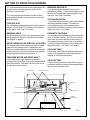
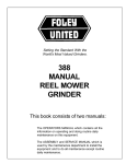
GETTING TO KNOW YOUR GRINDER
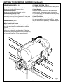
Fig. 1 shows the major areas of the Grinder which will
be referred to in the operating instructions in the
remainder of this manual.
BEDKNIFE SUPPORTS
Two electromagnets assemblies support the
bedknife for grinding. A fixed electromagnet on the
left end, and an adjustable electromagnet on the
right end. See Page 9 for details.
The next few pages show details of some of those
areas and point out the various controls you will use
when operating.
TOOLING ROTATION
The control box contains the electrical controls for the
Grinder. START and STOP switches are located on
the top panel. See Page 7 for details.
To grind the top face and front face of the bedknife
the tooling assembly rotates. This rotation is
accomplished through an electromechanical
actuator with calibrated stop pins to set the correct
angle. See Page 11 for details.
GRINDING HEAD
PROXIMITY SWITCHES
The grinding head consists of the grinding wheel and
safety guard, and the motor which drives the wheel.
See Page 8 for details.
Two movable switches determine the left and right
limits of carriage traverse. An LED on the switch
lights when the switch actuator on the bottom of
the carriage gets close to the head of the switch
(touching the switch head with a steel object will
trigger the switch). See Page 11 for details.
CONTROL BOX
DRIVE CARRIAGE AND VERTICAL ADJUSTER
The carriage and vertical adjuster provide a movable
support for the grinding head. A handwheel (see
Page 8 for details) adjusts the grinding wheel position
forward and back. An eccentric cam and lock adjusts
the grinding wheel position up and down.
COOLANT TANK
A tank which sets under the Grinder holds liquid
coolant to be sprayed onto the bedknife during
grinding, to minimize heat buildup.
TRAVERSE MOTOR AND DRIVE SHAFT
A drive shaft with a linear actuator traverses the
carriage from side to side, to move the grinding wheel
along the bedknife. The shaft is driven by a motor at
the right end of the machine.
GRINDING HEAD
COOLANT TRAY
A large tray along the back of the Grinder serves
as a splash guard and collects the splashed liquid
for return to the Coolant Tank.
BEDKNIFE SUPPORTS
CONTROL BOX
DRIVE CARRIAGE
TRAVERSE MOTOR
PROXIMITY SWITCHES
STANDBY
POWER SUPPLY
COOLANT TRAY
COOLANT TANK
9
FIG. 1
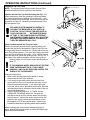
GETTING TO KNOW YOUR GRINDER (Continued)
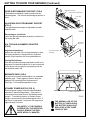
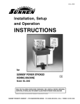
CONTROL PANEL (FIG. 2)
TRAVERSE FT./MIN KNOB
Controls the travel speed of the carriage and grinding head,
from 0 - 35 feet [0 - 10.7 meters] per minute.
TRAVERSE KNOB
ELECTROMAGNET
TOOLING POSITION
START Button (Green)
Acts as a reset button after STOP has been pressed. The
grinding motor switch must be in the off position or the guard
door must be closed or the start button will not reset.
IF THE TRAVERSE SWITCH OR THE
COOLANT PUMP SWITCH ARE IN THE
ON POSITION, THEIR FUNCTIONS
WILL IMMEDIATELY START WHEN
START IS PRESSED.
STOP
CARRIAGE TRAVERSE
START
COOLANT PUMP
GRINDING WHEEL
STOP Button (Red)
Shuts down power to the Grinder with the exception of
the electromagnets.
CARRIAGE TRAVERSE Switch (ON/OFF)
Controls electrical power to the motor which turns the drive
shaft to traverse the carriage.
GRINDING WHEEL Switch (ON/OFF)
Controls electrical power to the grinding head motor. This
switch is tied into the door interlock. This switch will
function only when the door is closed.
COOLANT PUMP Switch (ON/OFF)
Controls electrical power to the flood coolant system.
FOR SAFETY, WHENEVER
STOP IS PRESSED TO SHUT
DOWN THE MACHINE, SHUT
OFF ALL SWITCHES, EXCEPT
FOR THE ELECTROMAGNET
SWITCH. YOU CAN THEN
PRESS START TO START THE
GRINDER.
ELECTROMAGNET SWITCH and LIGHT (ON/OFF)
Controls electrical power to the electromagnets for holding
the bedknife and bedbar.
This switch is independent from the start and stop
switches and is powered through the standby power
supply. Green light indicates power to magnets is on.
TOOLING POSITION SWITCH (MOMENTARY)
Controls DC electrical power to the tooling rotation
actuator. Pushing up causes the tooling to rotate up to the
preset top face stop. Pushing down causes the tooling to
rotate to the preset front face stop.
The START and STOP buttons control the main power to
the Grinder, except the electromagnets which are
independently powered. Use the other switches to
control the separate operating functions. To start the
grinding operation: With all switches OFF and the guard
door closed, press the START button. Turn the
GRINDING WHEEL switch ON. Turn the COOLANT PUMP
and CARRIAGE TRAVERSE switches ON.
10
FIG. 2
ALWAYS TURN THE GRINDING
WHEEL ON FIRST, TO AVOID A
VOLTAGE DROP TO THE
REVERSING CIRCUIT OF THE
CARRIAGE TRAVERSE.
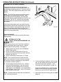
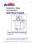
GETTING TO KNOW YOUR GRINDER (Continued)
DRIVE CARRIAGE (FIG. 3)
COOLANT SYSTEM (FIG. 3)
See Page 14 for more information about the system.
Vertical Eccentric Adjustment and Lock
Moves the grinding head up and down.
Horizontal Handwheel
Moves the grinding head infeed in and out.
Horizontal Adjustment Scale
Calibrated in .002 in [.05mm] increments, so you can
accurately move the grinding wheel in for each pass
across the face of the bedknife.
GRINDING HEAD (FIG. 3)
Coolant Nozzle
Directs a stream of coolant onto the bedknife and
grinding wheel, if the coolant system is turned on.
For precise aiming, the nozzle and connecting tubing
are completely flexible.
Coolant Flow Valve
Controls the volume of coolant flowing to the nozzle.
Use only enough flow to cool the bedknife. Excess
flow will cause excess splashing - and won't improve
performance.
Wheel Guard Lock Screws
A T-knob holds the guard in position. Loosen it to
pivot the guard when the guard interferes with the
bedbar.
Diamond Wheel Dresser
Allows you to dress the grinding wheel. Cleaning
and dressing the grinding wheel improves the quality
of the grind. See Page 13 for more information.
Fig. 3
11
GETTING TO KNOW YOUR GRINDER (Continued)
FIXED ELECTROMAGNET
FIXED ELECTROMAGNET SUPPORT (FIG.4)
The bedknife and bedbar is held in position by two
electromagnets. The left side electromagnet position is
fixed.
ADJUSTABLE ELECTROMAGNET
LOCK KNOB
ADJUSTABLE ELECTROMAGNET SUPPORT
(FIG. 4)
The right side electromagnet is adjustable to match
bedknife width.
BEDKNIFE GAGE
FIG. 4
Electromagnet Lock Knob
Locks the right electromagnet assembly in position on
the tooling bar slide.
ZEROING DIAL
INDICATOR
R.H. TOOLING ALIGNMENT ADJUSTER
(FIG 5)
Adjustment Handwheel
Adjusts the right side of the tooling assembly to allow
the tooling assembly to be adjusted out of parallel
position to get maximum life from used bedknives.
TOOLING ADJUSTMENT
HANDWHEEL
Zeroing Dial Indicator
After the right side adjustment has been moved out of
alignment to maximize bedknife life, it can be returned
to the factory set zero position by adjusting until the
dial indicator reads .500.
FIG. 5
BEDKNIFE GAGE (FIG.4)
On the outside of each electromagnet is a retractable
bedknife gage. These gages are used to align the
bedknife to the grinding wheel carriage travel.
See Page 17 for detailed explanation of use.
STANDBY POWER SUPPLY (FIG. 6)
Electromagnetic energy holds the bedknife/bedbar
assembly in place during grinding. If the power is
interrupted at an outside source, the bedknife would
release. To avoid this situation, a Standby Power
Supply is connected into the electromagnet circuit. If
the power is interrupted, it will power the magnets for
approximately 5 minutes.
STANDBY POWER SUPPLY
FIG. 6
THE NORMAL LIFE OF THE
BATTERY IS THREE YEARS.
THE BATTERY SHOULD BE
REPLACED AFTER THREE
YEARS OF USE.
FOR SAFETY, IF THE POWER IS
INTERRUPTED, THE OPERATOR
SHOULD REMOVE THE BEDKNIFE WITHIN 3-5 MINUTES.
12
GENERAL OPERATING INFORMATION
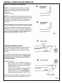
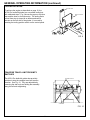
WHEN TO SHARPEN THE BEDKNIFE
NOTE: To fully sharpen a reel mower, you need to
grind the reel blades (using a Reel Grinder) and reshape the cutting edge of the bedknife (using the
ACCU-Pro
Bedknife Grinder).
NOTE: New bedknives should be ground before being
put into use. New bedknives deform and move to match
the shape of the bedbar at the time of installation and
therefore must be ground to a straight surface after
installation.
When the grass is not being cut cleanly, or the cut ends
of the grass appear torn or ragged, the edges of the reel
blade and bedknife have become rounded and need
sharpening. See FIG. 7A. The purpose of sharpening
is to restore the sharp edges to the reel and bedknife as
well as to return the mowing unit to the manufacturers
recommended configuration. See FIG. 7B.
O
BEDKNIFE GRINDING ANGLES
The bedknife has two faces that normally need to be
ground - the top face and the front face (on some
models, the front face may be curved and not need
grinding.)
The proper grinding angles for the two faces will vary,
depending on the reel manufacturer. Always follow
the manufacturer's recommended specifications
for bedknife angles.
Typically, however:
* There will be a +8 to -10 degrees clearance
angle ground on the top face. It will usually be
measured relative to the bedknife mounting
surface. See FIG. 8-A.
* There will be a 0-30 degrees clearance angle
ground on the front face. It will usually be
measured relative to a line perpendicular to
the bedknife mounting surface. See FIG. 8-B.
O
How to obtain these angles is discussed in more detail
in the operating instructions, beginning on Page 16.
13
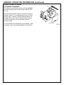
GENERAL OPERATING INFORMATION (continued)
TOOLING ROTATION
TOP FACE STOP
To achieve the angles as described on page 10, the
ACCU-Pro bedknife grinder has a movable tooling bar
with calibrated stops. Fig. 9 shows the upper or top face
stop and the lower or front face stop. The tooling bar is
moved from stop to stop with an electromechanical
actuator on the left side of the grinder. It is moved by
pressing the tooling position switch on the control panel.
FRONT FACE STOP
FIG. 9
TRAVERSE TRAVEL LIMIT PROXIMITY
SWITCHES
The ACCU-Pro bedknife grinder has proximity
switches to stop the carriage travel and reverse
direction. See Fig. 10. They are adjustable by
loosening the star knob and sliding the assembly
along the rail and retightening.
PROXIMITY SWITCH
STAR KNOB
FIG. 10
14
GENERAL OPERATING INFORMATION (Continued)
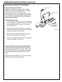
MOUNTING A GRINDING WHEEL
To replace the grinding wheel: See FIG. 11.
1. Turn the GRINDING WHEEL switch OFF.
2. Unscrew the mounting flange that holds the
grinding wheel, using a 3/4" open-end wrench.
3. Remove the old wheel and install the new one.
4. Screw on the flange finger tight, then tighten
approximately 1/8 turn further with the wrench.
It will self-tighten when the motor is turned on.
IF THE WHEEL FLANGE IS
OVERTIGHTENED, THE GRINDING
WHEEL MAY CRACK AND FLY
APART.
FIG. 11
5. After you install a new or different wheel, it is
recommended that you dress it before grinding.
Dressing trues the grinding surface of the wheel and
removes the hard glaze sometimes remaining from
the manufacturing process. This dressing properly
prepares the wheel for grinding. See Page 13.
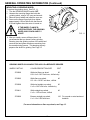
GRINDING WHEELS AVAILABLE FOR ACCU-Pro BEDKNIFE GRINDER
WHEEL PART NO.
COLOR/DESCRIPTION/SIZE
GRIT
3700060
White/red flare-cup wheel
60
6/3-1/4 x 2 0.627 inch bore, vitrified ruby
3700062
White flare-cup wheel,
6/ 3-1/4 x 2 0.627 inch bore, vitrified
3700268
White/red straight-cup wheel,
60
6 x 2 x 0.627 inch bore, vitrified ruby
3700411
White straight-cup wheel,
6 x 2 x 1.25 inch bore, vitrified
46
3700696
Borazon straight-cup wheel,
6 x 1-1/2 x 0.625 inch bore
120
46
For normal or extra hardened
bedknife.
,For more information on flare-cup wheels, see Page 15.
15
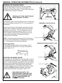
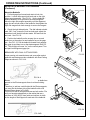
GENERAL OPERATING INFORMATION (Continued)
DRESSING THE GRINDING WHEEL
Dress the grinding wheel whenever there is any glazing
("glazing" is the buildup of stone dust, grinding grit, and
coolant on the face of the wheel). For best results, also dress
the wheel before making the final grind.
REFER ALSO TO THE "SAFETY RULES
WHEN GRINDING" ON PAGE 3.
FIG. 12
For dressing, always move the grinding head to the right hand
side of the machine as shown in FIG. 12, so you are clear of
the bedknife.
DRESSER IN LOCKED POSITION
With the wheel turning, lift the dresser movement arm off its
holder, push it forward and swing the dresser around to the
grinding face of the wheel. Turn the adjuster ring until the
diamond point just touches the wheel. See FIG. 13 or 14.
When completed, rotate handle clockwise against the lock
bracket before pulling back and replace the dresser
movement arm in the holder.
NOTE: Excessive dressing will shorten the life of the wheel
and may cause the diamond to be dislodged from the dresser
tip. To little dressing will inhibit proper grinding.
Replacing the Wheel
A new vitrified grinding wheel is 2" [51 mm] deep. When
it wears down to a depth of 0.75" [19 mm], it should be replaced. See FIG. 15.
DRESSER
DRESSER MOVEMENT ARM
LOCK BRACKET
FIG. 13
DRESSER UNLOCKED & READY TO USE
[19mm]
FIG. 15
ADJUSTMENT RING
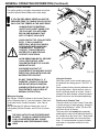
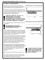
ROTATING THE WHEEL GUARD
Some bedknives and bedbars have mounting ears so close to
the bedknife top face that there is no clearance for the wheel
guard. For these applications, generally a flared cup grinding
wheel should be used and the grinding wheel guard can be
loosened and rotated so the clearance area of the guard
allows the bedknife to be ground without interference. When
completed, ALWAYS reposition the guard to its normal
position with the clearance notch down. See FIG. 16
FOR OPERATOR SAFETY, THE
GRINDING WHEEL GUARD MUST BE
USED WITH THE CLEARANCE AREA
UP ONLY WHEN REQUIRED FOR
BEDBAR CLEARANCE.
16
FIG. 14
WHEEL GUARD LOCK KNOB
FIG. 16
GENERAL OPERATING INFORMATION (Continued)
USING FLOOD COOLANT
For quality grinding, we highly recommend using flood
coolant to prevent heat buildup on the knife edge.
IF YOU DO DRY-GRIND, NEVER ALLOW THE
BEDKNIFE EDGE TO CHANGE COLOR OR YOU
MAY LOSE THE TEMPER IN THE KNIFE EDGE.
ALWAYS READ THE MATERIAL
SAFETY DATA SHEET (MSDS) FOR
THE COOLANT YOU ARE USING.
BELOW ARE WARNINGS THAT
APPLY TO MOST COOLANTS.
FIG. 17
AVOID CONTACT OF COOLANT WITH
EYES: IT WILL CAUSE EYE
IRRITATION. WEAR FACE SHIELD
OR GOGGLES WHEN HANDLING
CONCENTRATE. IN CASE OF
CONTACT, FLUSH EYES WITH
WATER FOR 15 MINUTES AND
CONTACT A PHYSICIAN.
AVOID BREATHING MISTS. PROVIDE
LOCAL VENTILATION. KEEP
CONCENTRATED BOTTLE CLOSED
WHEN NOT IN USE.
CONTINUED CONTACT OF
CONCENTRATE ON SKIN MAY CAUSE
IRRITATION. WASH WITH SOAP AND
WATER AFTER CONTACT.
DO NOT TAKE INTERNALLY. IF
INGESTED, CONSULT PHYSICIAN
AND DO NOT INDUCE VOMITING.
(HAZARD POTENTIAL APPLIES TO
CONCENTRATE, AND IS LESS AT
NORMAL USE DILUTION.)
Mixing the Coolant
Mix Part No. 3708620 Coolant in the Coolant Tank, at a
ratio of 50 parts water to 1 part concentrate. Refer also
to the label on the Coolant container. If the Tank is
empty,
this will take about 6 gallons of water and 1 pint of
concentrate [24 liters of water, and 0.5 liter of concentrate].
THE COOLANT RATIO AS SPECIFIED MUST
BE USED. TO HIGH A CONCENTRATION OR
LOW A CONCENTRATION WILL CAUSE
CORROSION AND PERFORMANCE PROBLEMS.
17
FIG. 18
Using the Coolant
Direct the nozzle so the coolant sprays onto
the bedknife face being ground. See FIG. 17
or 18.
Some coolant will then also be deflected onto
the grinding wheel. Adjust the flow valve so
there is a steady stream of coolant. Avoid a
stronger flow than needed, excessive coolant
doesn't cool more, and increases splattering.
Fluid Level in Coolant Tank
Check the fluid level in the Coolant Tank daily
to avoid running out while grinding. Keep the
coolant level between 1" and 4" [25 and 100
mm] from the top of the tray.
The pump inlet must always be completely
submerged in water. Never add plain water to
the coolant when the level is low. Always add
water and concentrate in the correct proportions. It is recommended to pre-mix coolant
and water in a separate container for this
purpose.
GENERAL OPERATING INFORMATION (Continued)
USING A FLARE CUP WHEEL
FOR ADDED CLEARANCE
The shape of some bed bars requires using an optional
flare-cup grinding wheel to clear the end supports. See
FIG. 19.
Flare-cup wheels can be ordered in several 6" [150 mm]
diameter versions. For most applications, the 6" vitrified
wheel is used. However, if the end mounting flanges of
the bedknife are more than 2" [50 mm] high or near the
front face of the knife, you may need the optional 6"
flared cup wheel.
For Part Numbers and descriptions of all available grinding wheels, refer to the Grinding Wheels list on Page 12.
18
FLARED-CUP WHEEL
FIG. 19
OPERATING INSTRUCTIONS (Continued)
MOUNTING A BEDKNIFE FOR GRINDING
Inspect and Clean the Bedknife
Inspect the bedknife for damage (cracks, warping,
bushing wear, excessive bedknife wear). Replace or
repair if necessary, see the mowing unit
manufacturer's manual. Thoroughly clean the bedknife, especially on the bottom where the electromagnets will attach. It is recommended to thoroughly
wire brush these areas.
TOP FACE STOP PIN
FRONT FACE STOP PIN
Set the Bedknife Angles
1. From the Mowing Unit manual or from the Mowing
Unit manufacturer, determine what the correct top
face angle and front face angle is for your bed
knife. See Page 10.
2. Move the tooling Rotation Actuator so the tooling
bar stop is at midpoint between the front face stop
and the top face stop. See Fig. 20.
FIG. 20
3. Move the Tooling Rotation stop pin for the front
face to the correct angle. See Fig. 20.
4. Move the Tooling Rotation stop pin for the top face
to the correct angle. See Fig. 20.
Prepare the Machine for Mounting the Bedknife
Pivot the tooling assembly to the horizontal position
(Front face grinding position). Traverse it all the way
to the right, then crank the carriage back (away from
the electromagnets) to gain clearance for the bedknife.
Always wipe any grindings, dirt, etc. from the electromagnets before mounting the bedknife.
19
OPERATING INSTRUCTIONS (Continued)
MOUNTING A BEDKNIFE FOR GRINDING
(Continued)
MAGNET LOCK KNOB
Mount the Bedknife
1. Pull both gage tips forward and rotate to lock into
position. Loosen the magnet lock knob and on the right
side magnet assembly. See FIG. 21. Set the bedknife /
bedbar assembly to be ground on the electromagnets.
Move the right side magnet assembly until the alignment
gage tips are at both ends of the bedknife, then tighten the
right side magnet lock knob enough to secure the magnet.
2. Check the right side adjuster. The dial indicator should
read .500. If not, loosen the lock tee knob and, adjust the
handwheel until the dial indicator reads .500 and lock the
tee knob. See FIG. 22.
3. Position the bedknife so the unworn tips on a used
bedknives or the ends of a new bedknife are on the gage
tips. See FIG. 23 Pull the bedknife forward firmly against
the gage tip and then turn on the electromagnets. See FIG.
24. The red light will come "on" on the control panel. Turn
and park both alignment gage tips.
GAGE TIP
FIG. 21
LOCK KNOB
BEDKNIVES WITH DUAL CUTTING EDGES
Some mowing unit manufacturers and some after market
bedknife manufacturers make a bedknife with Dual Cutting
Edges as shown in FIG. 24 A.
FIG. 22
FIG. 24 A
Because of the two radiused surfaces that these bedknives
present to the Electromagnets there is minimal holding
force.
Therefore, to achieve a solid hold with the Electromagnets,
you must file the bottom side of the bedknife with a flat
bastard file as shown in Fig 24 B.
You must file with a uniform stroke across both radius: File
until you have developed flats on the radius that are a
minimum of 3/32(.09) [2.3mm] wide and uniform in width
for the length of the magnet on each end of the bedknife.
FIG. 23
FIG. 24
FIG. 24 B
20
OPERATING INSTRUCTIONS (Continued)
ALIGNING TO A WORN BEDKNIFE
This alignment method is different than the alignment
GRINDING WHEEL AT LEFT END OF BEDKNIFE
detailed on page 17 in that in this alignment you are aligning
the worn bedknife faces to the grinding head traverse.
The reason for using this method is that some bedknives are
worn unevenly primarily due to the reel adjustments. To get
the maximum life from these bed knives and remove the least
stock, you may want to grind them using the
established surfaces as the alignment.
SOME REEL ASSEMBLIES, ESPECIALLY ON
GREENS MOWERS, HAVE A MINIMAL
ADJUSTMENT RANGE. BE SURE THE
MISALIGNMENT YOU USE IS WITHIN THE RANGE
OF THE REEL ASSEMBLY SO YOU CAN ACHIEVE
PROPER REEL TO BEDKNIFE ADJUSTMENT.
FIG. 25
GRINDING WHEEL AT RIGHT END OF BEDKNIFE
This is accomplished by touching the grinding wheel to the
worn bedknife.
THE BEDKNIFE MAY SLIDE ON THE
ELECTROMAGNETS IF YOU INFEED THE
GRINDING WHEEL EXCESSIVELY.
With the bedknife / bedbar mounted per procedure on page
17 and in the front face grinding position. Move the grinding
head to the left end of the bedknife. Now adjust the carriage
infeed handwheel until the wheel just touches the bedknife
inside the unworn end nib. See FIG. 25.
FIG. 26
Next, move the grinding head to the right end of the bedknife.
Now without moving the grinding head infeed, loosen the lock
tee knob and adjust the tooling bar right side adjuster until
the grinding wheel just touches the bedknife inside the
unworn end nib. See FIG. 26. Because when you adjust the
right side, the left side also moves a small amount, you
should go to the left and right sides several times to verify
that you just contact the knife at both ends.
Now lock the lock tee knob on the right side adjuster and
check the dial indicator. The dial indicator reading difference
from .500 is the amount you have adjusted the grind out of
correct alignment. Make certain that this setting is within
the range of adjustment of your mowing unit. (If not, a
compromise offset will be
required.)
Grind the front face per the instructions on Page 19 and
20.
Then, rotate the tooling bar to the Top Face position and
repeat the above procedure to offset the Top Face. Grind
the top face per the instructions on Page 21-24.
21
YOU MUST RETURN THE TOOLING
ASSEMBLY RIGHT SIDE ADJUSTER
BACK TO THE .500 POSITION FOR
THE NEXT BEDKNIFE OR YOU WILL
GRIND IT INCORRECTLY
OPERATING INSTRUCTIONS (Continued)
GRINDING THE FRONT FACE
TOP FACE STOP PIN
NOTE: The following instructions presume that you have
already studied all previous sections of this manual.
NOTE: On some mower bedknives, the front face is curved
and therefore may not have to be sharpened.
FRONT FACE STOP PIN
Position the Head for Front-Face Grinding
(See Fig. 27)
If you have not preset the front face angle and top face angle
stops, do so at this time per the procedure on page 16.
Rotate the tooling assembly to the front face position (down).
Check Clearances and Set Traverse Limits
Position the grinding head so that the grinding wheel just
touches the front face of the bedknife. With the vertical cam
and lock lever, adjust the grinding head so the grinding wheel
rim extends 1/2" [12mm] or as much as possible above the
front face to be ground. See FIG. 28.
FIG. 27
IF THE GRINDING WHEEL RIM DOES NOT EXTEND
OVER THE BEDKNIFE FACE, IT WILL WEAR
UNEVENLY AND CAUSE GROOVES ACROSS THE
SURFACE OF THE BEDKNIFE.
Check for interference:
1. Back out the grinding head so the wheel no longer touches
the front face of the bedknife.
2. Slide the left and right proximity switches to the far ends of
the rail. Leave their knobs loose.
3. Set the TRAVERSE knob at 4 - 5 FT./MIN. Set the
CARRIAGE TRAVERSE switch ON. Traverse the carriage
to the left until the contact area of the grinding wheel is
about 1" beyond the area to be ground on the bedknife,
then turn the traverse potentiometer to zero. Be prepared
to STOP the traverse earlier if there is any interference
between the grinding wheel and the bedbar.
FIG. 28
With the carriage still in the position determined in Step 3
above, slide the left proximity switch in until its LED lights, then
tighten the proximity bracket knob.
Traverse back to the right until the grinding wheel reaches the
point where it covers the entire area to be ground and goes
past that point by 1" [25 mm] or more if possible. Then set the
right proximity switch in the same manner.
FIG. 29
NOTE: The area of the grinding wheel which contacts the
bedknife is on the left side of the wheel. When grinding the
left end of the bedknife, the area of the wheel which doesn't
contact the bedknife will still be over the bedknife.
See FIG. 29. When you go to the right end of the Grinder,
the wheel traverses completely off the bedknife.
Infeed the grinding wheel until it very lightly touches the
bedknife on the left side. Now traverse to the right end of the
bedknife to assure that the right side is not closer to the grinding wheel. Back the wheel out if necessary until you can
traverse full length with a very light touch at the closest point.
22
OPERATING INSTRUCTIONS (Continued)
GRINDING THE FRONT FACE (Continued)
Grind the Bedknife
When you are satisfied with the grinder head travel, begin
ing:
grind-
REFER TO THE
"SAFETY RULES WHEN GRINDING"
ON PAGE 3.
NOTE: During the grinding process, watch the spark pattern for
the full length of grind, the sparks should look equal for the full
length of grind.
1. With the guard door closed, set the GRINDING WHEEL
switch at ON.
2. Set the COOLANT PUMP switch at ON, and check that the
nozzle is directing coolant onto the bedknife. See FIG. 17.
3. Set the TRAVERSE knob at about 12 FT/MIN.
NOTE: If an excessive amount of metal stock will have to be
removed on one end of the bedknife, recheck your setup first and
then the straightness of the bedknife. If it is bowed or twisted,
replace it.
4. Set the carriage traverse switch ON. With the horizontal
infeed handwheel crank the grinding head in (clockwise) until
the wheel is removing metal lightly from the bedknife. It is
recommended to take off about .002 to .003" [.05 to .075 mm]
per pass.
NOTE: The horizontal adjustment dial is calibrated in
.002" [.05 mm] increments.
5. Continue grinding the bedknife in this manner until you are
satisfied with the front face grind. Dress the wheel when
necessary. (see "Dressing the Grinding Wheel" on Page 13)
6. Dress the wheel before the final spark out grind. For spark
out procedure, see the top of page 23.
By partially grinding both surfaces, the top face and the front face,
as shown in FIG. 30, you will resharpen a used bedknife with the
least metal removal. FIG. 30 also shows how much stock would
be removed if you ground the top face surface until sharp. Partially grinding both surfaces is the preferred method for life utilization of the bedknife.
SHUT OFF THE COOLANT PUMP SWITCH
BEFORE YOU SHUT OFF THE GRINDING
WHEEL, TO ALLOW THE WHEEL TO SPIN DRY.
IF THE WHEEL RETAINS TOO MUCH COOLANT,
IT WILL BE UNBALANCED WHEN YOU AGAIN
TURN ON THE GRINDING MOTOR.
23
FIG. 30
OPERATING INSTRUCTIONS (Continued)
GRINDING THE TOP FACE
NOTE: The following instructions presume that you have
already studied all previous sections of this manual.
TOP FACE STOP PIN
Position the Head for Top-Face Grinding (See Fig. 31 )
When rotating from front face grinding to top face grinding,
the grinding head must be backed out two full turns. If you
have not preset the top face angle, do so at this time per the
procedure on Page 16. Rotate the tooling assembly to the
top face position (up).
BECAUSE ELECTROMAGNETIC ENERGY IS
HOLDING THE BEDKNIFE IN THIS VERTICAL
POSITION. DO NOT LEAVE THE BED KNIFE IN
THIS POSITION FOR
EXTENDED PERIODS
OF TIME. IF THE POWER WOULD INTERRUPT,
THE STANDBY POWER SUPPLY WILL HOLD THE
BEDKNIFE FOR APPROXIMATELY 10 MINUTES,
THEN THE BEDKNIFE WILL FALL.
FIG. 31
Check Clearances and Set Traverse Limits
Position the grinding head so that the grinding wheel just
touches the top face of the bedknife. Check to see if the rim
of the grinding wheel is extended 1/2" [50mm] above the top
face of the grinding wheel. If you have previously ground the
front face it most often will be correct. If not, with the vertical
cam and lock lever, adjust the grinding head. See Fig. 32. If
the shape of the bedbar interferes with the wheel guard or
grinding wheel you will need to make adjustments per
page 15.
IF THE GRINDING WHEEL RIM DOES NOT EXTEND
OVER THE BEDKNIFE FACE, IT WILL WEAR
UNEVENLY AND CAUSE GROOVES ACROSS THE
SURFACE OF THE BEDKNIFE.
Check for interference:
1. Back out the grinding head so the wheel no longer
touches the top face of the bedknife.
2. If you have just ground the front face the travel limit
should still be correct, but you should still verify no inter
ferences as described below. If you did not grind the
front face, follow the full procedure listed below. Slide the
left and right proximity switches to the far ends of the rail.
Leave their knobs loose.
3. Set the TRAVERSE knob at 4 - 5 FT/MIN. Set the
CARRIAGE TRAVERSE switch ON. Traverse the
carriage to the left until the contact area of the grinding
wheel is about 1" beyond the area to be ground on the
bedknife, then turn the traverse potentiometer to zero.
Be prepared to STOP the traverse earlier if there is any
interference between the grinding wheel and the bedbar.
With the carriage still in the position determined in Step 3
above, slide the left proximity switch in until its LED lights, then
tighten the proximity bracket.
24
FIG. 32
OPERATING INSTRUCTIONS (Continued)
GRINDING THE TOP FACE (Continued)
Traverse back to the right until the grinding wheel
reaches the point where it covers the entire area to be
ground and goes past that point by 1" [25 mm] or more if
possible. Then set the right proximity switch in the same
manner.
NOTE: The area of the grinding wheel which contacts
the bedknife is on the left side of the wheel. When
grinding the left end of the bedknife, the area of the
wheel which doesn't contact the bedknife will still be over
the bedknife. See FIG. 33. When you go to the right
end of the Grinder, the wheel traverses completely off
the bedknife.
Infeed the grinding wheel until it very lightly touches
the bedknife on the left side. Now traverse to the right
end of the bedknife to assure that the right side is not
closer to the grinding wheel. Back the wheel out if
necessary until you can traverse full length with a very
light touch at the closest point.
FIG. 33
Grind the Bedknife
When you are satisfied with the grinding head travel,
begin grinding:
REFER ALSO TO THE
"SAFETY RULES WHEN GRINDING" ON
PAGE 3.
NOTE: At this point you won't know the condition of
the grinding wheel after the previous job. Always
dress the wheel before grinding. See Page 12.
1. With the guard door closed, set the GRINDING
WHEEL switch at ON.
2. Set the COOLANT PUMP switch at ON, and
check that the nozzle is directing coolant onto the
bedknife. See FIG. 18.
3. Set the TRAVERSE knob at about 12 FT/MIN.
NOTE: If an excessive amount of metal stock will
have to be removed on one end, recheck your setup
first and then check the straightness of the bedknife.
If it is bowed or twisted, replace it.
5. Continue grinding the bedknife in this manner
until you are satisfied with the top face grind.
Dress the wheel when necessary. (See
"Dressing the Grinding Wheel" on page 13).
4. Set the carriage traverse switch at on. With the
horizontal infeed handwheel, crank the head in
(clockwise) until the grinding wheel is removing
metal lightly from the bedknife. It is recommended
to take off about .002 to .003" [.05 to .075 mm] per
pass during the rough grind.
During the grinding process, watch the spark
pattern for the full length of grind, the sparks
should look equal for the full length of grind.
NOTE: The horizontal adjustment dial is calibrated in
.002" [.05 mm] increments.
6. Dress the wheel before making the final spark
out grind.
25
OPERATING INSTRUCTIONS (Continued)
GRINDING THE TOP FACE (Continued)
On the spark out passes, crank the grinding head in (clockwise) only about .001" [.025 mm] and then let the grinding
wheel spark out. For sparking out, always traverse the
grinding head 10 - 20 passes without cranking the grinding
head in further. To get the finest top-face grind, set the
TRAVERSE knob at slow speed (about 5 FT/MIN) for this
final grinding sparkout. This process improves the surface
finish of the grind and improves the grind quality.
NOTE: What you are looking for is a "near sparkout" about a 99% reduction in grinding spark from a normal
grind. Don't
continue sparking out until you have no
sparks, because this could be an extremely long time.
SHUT OFF THE COOLANT PUMP
SWITCH BEFORE YOU SHUT OFF THE
GRINDING WHEEL, TO ALLOW THE
WHEEL TO SPIN DRY. IF THE WHEEL
RETAINS TOO MUCH COOLANT, IT WILL
BE UNBALANCED WHEN YOU AGAIN
TURN ON THE GRINDING MOTOR.
If after grinding, when the bedknife / bedbar assembly is
installed in the mowing unit and it does not appear to be
ground straight, the right side adjuster on the tooling bar
should be verified to be perfectly straight to the grinding
head traverse rails.
To verify, use the optional Magnetic Base Dial Indicator
(Part no. 6100501). Set the top face angle pin at 0 degrees and rotate the tooling assembly to the top face grind
position. Install the magnet base on the top of the motor
with the arm extended so the dial indicator touches the
electromagnet face. See Fig. 34. Disengage the traverse
actuator with the release lever. Slide the grinding head
from magnet to magnet. The dial indicator on the magnetic
base should read zero (No change from magnet to magnet). If it does not, loosen the right side tooling bar adjuster
lock tee knob and then adjust the right side adjuster handwheel until you get zero / zero across the two magnets.
When this is achieved, relock the tee knob. Now, adjust
the machine dial indicator which is mounted to the right
side tooling adjuster so it reads .500. This is done by
loosening the setscrew that holds the dial indicator, repositioning the indicator and retightening the setscrew. Bedknives ground with this setting, (The same as the factory
original setting.) should be correct.
REMOVING THE BEDKNIFE
Remove the bedknife by rotating the tooling assembly to
the front face grinding position (down). Grasp the bedknife
and turn off the electromagnet. If the next bedknife to be
ground is the same type and size as the previous, simply
mount it and proceed.
26
FIG. 34