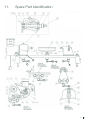
1
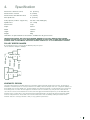
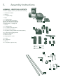
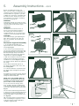
DML36SH-MKII
Swivel Head Lathe
Instruction
Manual
IMPORTANT
For your safety read
instructions carefully before
assembling this product.
Save this manual for
future reference.
Woodworking Machines & Accessories
Record Power Ltd
Unit B, Adelphi Way
Staveley S43 3LS
Telephone: 0870 770 1777
Facsimile: 0870 770 1888
Email: [email protected]
http://www.recordpower.co.uk
Contents
Terms & Conditions Of Usage
Introduction
page 3
1.
Health & Safety Guidance
page 4
2.
Additional Safety Instructions For Woodturning
page 5
3.
Record Power Guarantee
page 6
EU Declaration of Conformity
page 26
User Manual
Consumable spare
parts quick find
4.
Specification
page 7
5.
Assembly Instructions
page 8
6.
Connection Of The Electricity Supply
page 15
7.
Wiring Information
page 15
8.
Control Identification & Function
page 16
9.
Lathe Operation
page 17
10.
Maintenance
page 21
11.
Spare Part Identification
page 23
12.
Genuine Record Power Accessories
page 25
Part Description
Part Number
10” Toolrest
Handwheel
Bearing – 6202ZZ
Bearing – 6204ZZ
Main spindle
Poly V-belt, 4 rib
Tool rest base (Banjo)
M8 Ratchet handle - Toolrest
Tailstock locking handle
Pry bar #
Dog point knob
Banjo locking handle
M12 x 80mm Cup Sq neck bolt
M12 Nut
ZCF - CLO/J
ZBA
ZABD
ZABE
ZBQ
ZBO - CLO/I
ZBE
CLRC
BOBT
ZCA
CLKB
BOBT/DML
CKCB
ZABM
# Not illustrated in parts diagram
Introduction
Dear Customer,
Thank you for investing in a RECORD POWER® WOODTURNING LATHE, which has been designed to give you years of satisfying
service.
A complete list of accessories to enhance your enjoyment of woodturning is included at the back of this manual.
Please do not forget to fill in and return your guarantee card, this will assist us in providing you with prompt and appropriate after
sales service. (This does not affect your statutory rights).
PURPOSE OF THIS MANUAL
This manual serves to give details of Specification, Health & Safety, Installation & Assembly, it does not serve to teach you the art
and skill of Woodturning. This is best done by either attending a course run by a skilled woodturner, obtaining one of the many
publications on the subject and by viewing our website (www.recordpower.co.uk) where you can find various woodturning tuition
articles and projects. Please ensure you have sufficient basic skill before using this machine. We also run free courses at our training
school near junction 30 of the M1. For details, please call 0870 7701777.
RECORD POWER AND THE ENVIRONMENT
Considerations of environmental issues are an integral part of the design, production and other associated aspects of this product,
and all reasonable environmentally friendly options have been adopted throughout.
Users are advised to consider environmental issues associated with the use of this product, particularly when considering workpiece
material. Confirmation of sourcing from well-managed forests is advisable whenever practically possible.
WASTE ELECTRICAL AND ELECTRONIC EQUIPMENT (WEEE) REGULATIONS
The WEEE regulations aim to encourage reuse, recycling and recovery of electrical and electronic waste. The document outlining the
WEEE guidelines is available at http://www.dti.gov.uk/sustainability/weee.
2
3
1.
Health & Safety Guidance
READ ALL THE INSTRUCTIONS IN THIS MANUAL
CAREFULLY BEFORE ASSEMBLY, INSTALLATION AND USE
OF THIS PRODUCT.
KEEP THESE INSTRUCTIONS IN A SAFE PLACE FOR
FUTURE REFERENCE.
WARNING: When using electric tools, basic safety precautions
should always be followed to reduce the risk of fire, electric
shock and personal injury.
SAFE OPERATION
1. Eye Protection
The operation of any machinery or power tool can result in
foreign objects being thrown into your eyes, which can result
in severe eye damage. Always wear safety glasses or other
suitable eye protection. Wear safety glasses at all times when
using the machine. Everyday glasses only have impact resistant
lenses. They are not safety glasses which give additional lateral
protection. We also advise that ear protectors are worn to avoid
damage to hearing.
2. Keep work area clear.
Cluttered areas and benches invite accidents and injuries.
3. Consider work area environment.
Do not expose the machine to rain or damp conditions.
• Keep the work area well lit.
• Do not use the machine in the presence of flammable
liquids or gases.
4. Guard against electric shock.
Avoid body contact with earthed or grounded surfaces.
5. Keep other persons away (and pets).
Do not let persons, especially children, not involved in the work,
touch the machine, or extension cord (if used) and keep visitors
away from the work area.
6. Store idle tools.
When not in use, tools should be stored in a dry locked- up
place, out of reach of children.
7. Do not force the machine.
It will do the job better and work more safely if operated at the
speed at which it was intended.
8. Use the right tool.
• Do not force small tools to do the job of a heavy-duty tool.
• Do not use tools for purposes not intended.
9. Dress properly.
• Non-slip footwear is recommended.
• Do not wear loose clothing, neckties or jewellery; they can be
caught in the moving parts.
• Roll up long sleeves above the elbow.
• Wear protective hair covering to contain long hair.
10. Use protective equipment
• Use safety glasses. (See note 1. above)
• Use face or dust shield if cutting operation creates dust.
11. Connect dust extraction equipment.
Use dust extraction whenever possible. Dust not only damages
and shortens the life of a machine but is also a serious health
risk.
12. Do not abuse the cord.
Never yank the cord to disconnect it from the socket. Keep the
cord away from heat, oil and sharp edges.
13. Secure work.
Ensure that your work piece is properly fixed before starting to
turn.
14. Do not overreach.
Keep proper footing and balance at all times.
15. Maintain tools with care.
• Follow instructions for lubrication and changing accessories.
• Inspect electric cords periodically and, if damaged, have them
repaired by an authorised service facility.
• Inspect extension cords (if used) periodically and replace if
damaged. Always use proper size extension cord.
16. Disconnect Machine.
When not in use, before making adjustments and servicing etc,
disconnect the machine from the power supply.
17. Never leave machine running unattended.
Turn power off, do not leave machine until it comes to a
complete stop.
18. Remove adjusting keys and wrenches.
If you using a chucking system ENSURE chuck key is removed
from chuck before switching the machine ‘ON’, any adjusting
wrenches should also be removed from the machine.
19. Avoid unintentional starting.
- Ensure the switch is in the “OFF” position before turning on
the power from the main electricity supply.
20. Out-door Extension Leads.
Your lathe should not be used outdoors.
21. Stay alert.
Watch what you are doing, use common sense and do not use
the lathe when you are tired.
22. Check for damaged parts.
• Before use of the machine, it should be carefully checked to
determine that it will operate properly and perform its intended
function.
• Check for alignment of moving parts, binding of moving parts,
breakage of parts, mounting and any other conditions that may
affect its operation.
• A guard or other part that is damaged should be properly
repaired or replaced by an authorised service centre unless
otherwise indicated in this instruction manual.
- Have defective switches replaced by an authorised service
centre.
• Do not use the machine if the switch does not turn on and off.
23. Warning!
• The use of any accessory or attachment, other than one
recommended in this instruction manual, or recommended by
Record Power may present a risk of personal injury.
24. Have your machine repaired by a qualified person.
• This electrical unit complies with the relevant safety rules.
Only qualified persons using original spare parts should carry
out repairs. Failure to do this may result in considerable danger
to the user.
Maintenance and Servicing
This unit requires very little maintenance. This handbook gives
clear instructions on installation, set up and operation.
Read these instructions carefully. Remember always to switch
off and unplug from the main electricity supply before carrying
out any setting up or maintenance operations.
Should you need advice the on repair or maintenance of this
product, our Customer Service Department ON 0870 770 1777
and they would be happy to assist you.
2.
Additional Safety Instructions
For Woodturning
SAFETY IS A COMBINATION OF OPERATOR
COMMON SENSE AND ALERTNESS AT ALL
TIMES WHEN THE LATHE IS BEING USED.
WARNING: For your own safety, do not attempt to operate
your lathe until it is completely assembled and installed
according to the instructions and you have sought adequate
training.
SAFE OPERATION
1. The Lathe should be bolted down to a stand or workbench
for stability.
2. Before attaching the workpiece to the faceplate always
“rough-out” to as “true round” as possible. This will minimise
vibration whilst turning.
3. Always rough out “out of round” workpieces at slow speed.
Running the lathe too fast could cause the workpiece to be
thrown from the lathe or the turning tool to be jerked from your
hands.
4. Always rotate the workpiece by hand before starting the
lathe. If the workpiece strikes the tool rest, it could be split and
thrown from the lathe.
5. Do not allow the turning tool to “bite” into the workpiece,
which could result in splitting or ejection of the workpiece from
the lathe. Always position the tool rest at the correct height so
that the tool cutting edge is on or above the workpiece centre.
6. Do not apply the turning tool to the workpiece below the
centre line of the lathe.
7. When using a faceplate always ensure the workpiece is well
secured.
8. Avoid awkward hand positions, where a sudden slip could
cause your hand to move into the workpiece.
9. Remove all loose knots and bark before attaching the
workpiece.
10. If turning tools are stored near the lathe, hang them on the
wall near the tailstock end of lathe. Do not lay them on a bench
so that you reach over the revolving workpiece to select them.
18. DO NOT perform any operations when hand holding the
workpiece.
19. DO NOT mount a reamer, milling cutter, wire wheel, buffing
wheel, drill bit or any other tool to the headstock spindle.
20. ALWAYS ensure that the turning tool is in contact with the
tool rest before commencing the cut.
21. When the tool rest base unit is not in use (as when sanding),
it should be moved away from the headstock, and the tool rest
removed.
22. It is normal for the motor to run hot. Therefore care should
be taken to avoid touching the motor, particularly when
changing the belt position on the stepped pulleys.
23. Warning Labels – It is important that labels bearing Health
& Safety Warnings are not removed or painted over. New labels
are available from Customer Services.
24. Mechanical Safety – The security of all clamps, guards and
work holding devices should be checked before switching on.
25. Wood Dust – The fine particles of dust produced in sanding
operations can be a long-term health hazard. Some woods
give off irritant dust that may cause a burning sensation. We
therefore strongly recommend the use of a dust collector on
your lathe and a suitable dust mask / visor. Our Customer
Services Department will be happy to advise you on the correct
unit for your needs.
26. This machine falls under the scope of the ‘Health & Safety
at Work etc. Act 1974’, and the ‘Provision & Use of Work
Equipment Regulations 1998’. We recommend that you study
and follow these regulations. Further guidance can be found
in the Safe Use of Woodworking Machinery code of practice
booklet (L114) published by Health & Safety Executive. This can
be found at http://www.hse.gov.uk/pubns/wis15.pdf
For further help on any of the above matters please contact our
Customer Services Department at :Tel: 0870 770 1777 Fax: 0870 770 1888
WARNING: Do not allow familiarity (gained from frequent use of
your machine) to cause complacency. Always remember that a
careless fraction of a second is sufficient to inflict severe injury.
11. Keep firm hold and control of the turning tool at all times.
Use extreme caution when knots and voids are exposed. The
turning tool could grab and be thrown, or dig into the workpiece
and break it apart.
12. Find and read the WARNING label incorporated within the
Machine Label mounted on the lathe motor.
13. Finish all hand sanding BEFORE removing the workpiece
from the lathe. Do not exceed the speed used for the last
cutting operation.
14. DO NOT remount a faceplate-turned workpiece to the
faceplate unless you are deliberately turning eccentric work.
You cannot remount faceplate turned work and have it run true,
as the timber will have expanded or contracted.
15. DO NOT remount between-centres turning if the original
centres have been altered or removed, unless you are
deliberately turning eccentric work. Set to the lowest speed
when remounting a between-centres turning.
16. Use extra caution when mounting a between-centres
or spindle turning to a faceplate, or a faceplate turning to
between-centres, for subsequent operations. ENSURE the lathe
is set at the lowest speed before switching ON.
17. DO NOT mount a workpiece that contains excessive splits,
shakes, or loose knots to a faceplate or between centres.
4
5
3.
Record Power Guarantee
1. INTRODUCTION
1.1 We supply machinery through a network of dealers and
authorised distributors and you should be aware that your
contract of sale is with the retailer from whom you purchased
this product.
1.2 If you are not satisfied with this product you should in the
first instance approach the retailer from whom you purchased it.
1.3 Customers have statutory rights to protect them and
information on this can be found at the Citizens Advice Bureau
or on such web-sites as that operated by the DTI (http://www.
dti.gov.uk)
1.4 Returning your guarantee card will speed up the claims
procedure and can be very helpful as a proof of purchase
should the initial receipt be mislaid or damaged. We recommend
that this is returned as close to your original purchase date as
possible.
1.5 Correct installation, set-up, adjustment and routine
maintenance of the machine are the responsibility of the enduser and problems arising from incorrect set-up, adjustment or
maintenance are not covered by the terms of this guarantee.
However support is available in the first instance from the
retailer who supplied you and free technical support is available
from Record Power on 0870 7701777 during office hours
and from an extensive knowledge base on our website www.
recordpower.co.uk. We also recommend those users who have
not had suitable training in safe use of machinery to seek such
training locally before using or attempting to set up and adjust
any machinery (please contact your retailer for recommendations
in your local area).
2. GUARANTEE
2.1 In addition to the above Record Power guarantees that for
a period of 5 years from the date of purchase the components
of this product will be free from defects caused by faulty
construction or manufacture.
2.2 During this period Record Power will repair or replace free
of charge any parts which are proved to be faulty in accordance
with paragraph 2.1 above provided that:
2.2.1 You follow the claims procedure set out below;
2.2.2 We are given a reasonable opportunity after receiving
notice of the claim of examining the product.
2.2.3 If asked to do so by us you return the product to Record
Power's premises or other approved premises such as those of
the supplying dealer, for the examination to take place.
2.2.4 The fault in question is not caused by continuous
industrial use, accidental damage, fair wear and tear,
wilful damage, negligence on your part, incorrect electrical
connection, un-approved modification, abnormal working
conditions, failure to follow our instructions, misuse, or alteration
or repair of the product without our approval.
2.2.5 This product has been purchased by you and not used for
hire purposes;
2.2.6 This Guarantee extends to the cost of carriage incurred
by you returning the product to Record Power as long as it
is demonstrated that the defect falls within the terms of this
Guarantee and you follow the claims procedure as outlined
below;
3. CLAIMS PROCEDURE
3.1 In the first instance please contact the retailer who supplied
the product to you. In our experience many initial problems with
machines that are thought to be due to faulty parts are actually
solved by correct setting up or adjustment of the machines.
A good dealer should be able to resolve the majority of these
issues much more quickly than processing a claim under the
guarantee.
3.2 If the dealer who supplied the product to you has been
unable to satisfy your query, any claim made under this
Guarantee should be made directly to Record Power at the
address set out at the foot of this Guarantee. The claim itself
should be made in a letter setting out the date and place of
purchase, and giving a brief explanation of the problem which
has led to the claim. This letter should then be sent with proof of
the purchase date (preferably a receipt) to Record Power. If you
include a phone number or email address this will help to speed
up your claim.
3.3 PLEASE NOTE that it is essential that the letter of claim
reaches the address below on the last day of this Guarantee at
the latest. Late claims will not be considered.
3.4 We will contact you once we have received your initial
written claim. If it is necessary to return the item, in most cases
but subject always to clause 2.2.5, we will arrange for collection
or will provide freepost information to enable return depending
on the weight and size of the product concerned. If the product
is to be returned to us, we will agree with you in advance a
Returns Number, to speed tracking of the claim and ensure the
most appropriate method of return to you is used.
4. NOTICE
This Guarantee applies to all goods purchased from an
authorised retailer of Record Power within the United Kingdom
of Great Britain and Northern Ireland. This Guarantee does not
confer any rights other than those expressly set out above and
does not cover any claims for consequential loss or damage.
This Guarantee is offered as an extra benefit and does not affect
your statutory rights as a consumer. Additional written copies of
this Guarantee can be obtained by writing to the address below.
Please include a stamped and self addressed envelope for each
copy of the Guarantee requested.
Record Power Ltd
Unit B, Adelphi Way
Ireland Industrial Estate
Staveley, Chesterfield
S43 3LS
4.
Specification
Max distance between centres
36” (914mm))
Max bowl Dia. over bed
9” (229mm)
Max bowl Dia. with DML-BR* fitted
12” (305mm)
Max spindle Dia.
6” (152mm)
Pulley Speeds (smallest - largest Dia.)
450, 950, 1500, 2000 (rpm)
Spindle Nose
3/4” x 16tpi
Motor Power:
1/3hp
Depth:
305mm
Width:
1295mm
Height:
298mm
Weight :
40kg
*DML-BR is an optional bowl rest attachment, available from all good stockists
HEADSTOCK SPINDLE AND TAILSTOCK BARREL BORED TO SUIT NO.1 MORSE TAPER SHANK.
SPINDLE FLATTED TO SUIT 9/16" WHITWORTH WRENCH TO FACILITATE FITTING AND RELEASE OF
SPINDLE NOSE ATTACHMENTS SUPPLIED. SPINDLE THREAD 3/4" X 16 TPI WHITWORTH THREAD.
PULLEY SPEED RANGES
By changing the belt on to each of the five different pulleys the speed
can be varied from 450rpm to 2000rpm.
2000rpm
1500rpm
950rpm
450rpm
Motor Pulley
Spindle Pulley
KINEMATIC DESIGN
Throughout this manual you will find references to kinematics and the kinematic design of this product. The principle of
kinematics is that three points of contact provide the most stability. The best example of this is to compare the stability of a
three legged stool and four legged stool. The three legged stool utilises the kinematic concept and will never rock because
it has three points of contact. The four legged stool however is far more unstable, only a tiny amount of distortion will
cause the stool to become unstable and move. Record Power apply the kinematic design theory to the DML36SH lathe,
wherever there is a critical piece of the structure being assembled kinematics are employed giving unsurpassed stability
and rock solid performance. Please take care to follow all instructions when assembling, making sure that all critical
kinematic areas are correctly positioned so that you enjoy optimum performance.
6
7
5.
Assembly Instructions
ASSEMBLY – IDENTIFYING CONTENTS
Inside the shipping container you will find the following:
1. Headstock & Saddle
2. Tailstock
3. 3 x Square Straps
4. Banjo
5. 2 x End Brackets
6. 2 x Wooden Bench Mounting
Washers (Not Required on DML24S
legstand, for use when mounting to
a wooden bench) - see page 10
1.
7. Toolrest
3.
8. 2 x Angle Straps
2.
9. 2 x Long Bolts (threaded bar)
4.
10. Ratchet Handle (Toolrest)
11. Long Stem Locking Handle & M12 Bolt (Toolrest)
12. 2 x Short Stem Locking Handle
(Headstock & Tailstock)
13. Tailstock Centre
14. Two prong drive centre
15. Pry Bar
5.
7.
16. 2 x Allen keys
6.
17. Spanner
18. 2 x Bed Bars (separate box)
8.
9.
10.
12.
11.
14.
13.
17.
15.
18.
16.
5.
Assembly Instructions
Before assembling and using your
lathe, you must have a sturdy bench or
stand for it. We recommend the Record
Power® DML24S Legstand. If you wish
to build your own bench, remember that
the lathe is heavy. The bench must not
move during use. For bench mounting
instructions see page 10.
- cont.
Fig.5.4B
Fig.5.1
WARNING
Inadequate strength of the bench could
result in failure of the bench, which could
cause the lathe to fall. Serious injury
could occur.
WARNING
The lathe must not shift or move. If
there is movement when the lathe is
not running, this movement will be
exaggerated when in use. Serious injury
could occur and work quality will suffer.
CAUTION
To avoid back injury, get help lifting the
lathe. Bend your knees, lift with your
legs, not your back. The headstock is
very heavy.
End Bracket
Wedge
Fig.5.5
Fig.5.2
Nut
Angle strap
Washer
Second End
Bracket (or
DML-BR
Bowl
Bracket)
Bed bars & legstand assembly
1. To assemble the bed bars and
legstand take one of the end brackets
and wedge Fig.5.1.
2. Unscrew the nut and washer from
one end of a long bolt and feed the long
bolt through the holes in the wedge, end
bracket and angle strap. Ensure that
the wedge is the correct way around in
relation to the end bracket Fig.5.2.
3. With the end bracket laid on the floor,
feed two of the stand legs up into the
end bracket as shown Fig.5.3. Replace
the washer and nut, but do not tighten at
this stage.
Nut
Wedge
Fig.5.3
Fig.5.6A
Ensure that the kinematic points on
the angle strap oppose this on the end
bracket Fig.5.4A.
4. Locate the bed bars in position under
the angle straps and tighten in position
Fig.5.4B.
Assemble the second set of legs with the
remaining end bracket, angle strap and
wedge as instructed above.
NOTE: If the optional DML-BR bowl
bracket is to be fitted use this in the
assembly procedure at this point in
place of the second end bracket.
Fig.5.4A
Opposing
Kinematic
Raised Points
5. Lay the second set of legs on the
floor. Hold the already assembled end
of the bed bars/legstand above the legs
on the floor and lower them into position
Fig.5.5.
The end of the bed bars/legstand which
is aloft must now be supported whilst the
end resting on the floor is tightened. It
may be advisable to seek assistance for
this Fig.5.6A.
NB: It may be useful to seek assistance
when assembling the legstand as some
of the procedures may be difficult to
complete single handed.
Recess
Kinematic
Raised Area
Second End Bracket (or
DML-BR Bowl Bracket)
8
9
5.
Assembly Instructions
7. Return the assembled legstand to
its upright position. It maybe useful at
this point to make sure that the legs
are all aligned correctly and adjust if
necessary. The bottoms of the legs are
angled slighlty to provide a solid base.
During assembly it is possible for the
legs to become twisted. To align the legs
slacken off the nut and twist the legs so
the angle on the bottom of the leg lies
flat on the floor Fig.5.6B
This alignment of the legs and bed
bars is crucial to the success of the
lathe assembly. Misalignment could
cause the headstock and tailstock to
be at an angle in relation to the bed
bars.
- cont.
Fig.5.6B
Fig.5.7B
Opposing
Kinematic
Raised Points
Recess
Kinematic
Raised Area
Fig.5.7A
Bed bars & Bench mounting
assembly: Fig 5.7
1. Position the end brackets roughly in
position at both ends of the bench.
NOTE: If the optional DML-BR bowl
bracket is to be fitted use this in the
assembly procedure at this point in
place of the headstock end bracket.
Mark out where to drill the holes
2. Place the bed bars on the end
brackets and space them accordingly
3. When you are satisfied that the end
brackets are in the correct position you
mark out where the holes will be drilled
to bolt the lathe to the bench Fig.5.7A.
4. Ensuring that the surrounding area is
clear, drill the holes using either a 1/2” or
13mm drill bit.
Fig.5.7B
Angle Strap
Nut & Washer
Tailstock End Bracket
Bed Bars
Drilled Hole in Bench
5. The end brackets and bed bars can
now be repositioned to align with the pre
drilled holes.
6. Place the square straps on each
end of the assembly ensuring that the
kinematic locations oppose each other
Fig.5.7B i.e. the raised area on the angle
strap opposes the recess on the end
bracket.
7. Pass the 12mm threaded bar through
the angle strap, end bracket and bench.
Place the washer and nut on to the top
of the bar and wind down approximately
four threads.
8. Do this on both end brackets.
9. Now fit the cast iron bench washer to
the exposed piece of threaded bar on the
underside of the bench and secure with
the second nut. Before fully tightening,
ensure that the bars are aligned straight
and supported by the end brackets.
Also double check to make sure that the
kinematic points are correctly positioned
i.e. recess opposing raised area.
10. Tighten both of the nuts on each
assembly against each other to secure
the end brackets.
Long Bolt (threaded bar)
Cast Iron Washer
Nut
Headstock End Bracket
(or DML-BR Bowl Bracket)
Bench
5.
Assembly Instructions
Attaching the tailstock
- cont.
Fig.5.10
Fig.5.8
1. Place the tailstock onto the bed bars
at the right hand end of the assembly
Fig. 5.8 (shown in reverse angle).
2. From behind, introduce the square
strap and tailstock locking handle
underneath the bed bars, ensuring that
the recess is to the front of the lathe
opposing the raised area on the tailstock.
Fig. 5.9.
3. Ensure hex nut is up against the roll
pin inside the tailstock and wind the
locking handle up into the nut until the
tailstock is firmly in place Fig. 5.10. You
may find it easier to use a spanner to
keep the nut in place whilst winding up
the lock handle.
4. Now take the tailstock centre and
place it into the barrel of the tailstock
Fig. 5.11.
Left
Right
Fig.5.9
Fig.5.11
Tailstock Centre
10
11
5.
Assembly Instructions
Banjo & Toolrest Assembly
Fig.5.12
1. Place the banjo onto the bedbars
where it will sit. Split the long stem
locking handle and bolt placing the
threaded bolt through the banjo. Now
offer the angle strap to the underside
of the bedbars and tighten the locking
handle onto the bolt Fig.5.12.
- cont.
Fig.5.13
Long stem locking
handle
2. Insert the toolrest into the banjo
and tighten the toolrest ratchet handle
Fig.5.13.
TIP
To improve comfort and fully tighten the
toolrest locking handle in all applications
of woodturning; rotate the coach bolt
into one of four different positions
through 360º. Every time a different
face on the nut is registered against the
registration face on the banjo, the handle
will lock in a different position. Fig. 5.14.
The diagram shows the approximate
position of where the handle will lock
when the corresponding hex nut face is
registered.
This principal also applies to both of the
Tailstock and headstock locking handles.
Every time a different face on the nut
is registered against the pin the handle
will lock in a different position. This is
necessary when sliding the headstock
and tailstock to the end of the bed bars
in order to prevent the locking handle
from fouling on the end bracket.
Fig.5.14
�
�
�
�
�
�
�
Locking Handle In
Position 1; Note Face
1 On The Hex Nut Is
Registered.
Registration face on the banjo
Coach Bolt
�
Numbers are for illustrative purposes only, actual components are not numbered.
5.
Assembly Instructions
Headstock
- cont.
Fig.5.15
Fig.5.20
1. Place the saddle on the bed bars
Fig.5.15.
1. Remove the cover plate from the
headstock using the Allen key Fig.5.16.
2. When fitting the remaining locking
handle and square strap ensure that
recess part of the square strap is on the
same side as the white indication line on
the saddle Fig.5.17. Carefully lower the
headstock onto the saddle, it is advisable
to angle the headstock assembly so the
motor rests on the bed bars, this will
bear most of the weight Fig.5.18.
Fig.5.16
Fig.5.21
3. Now feed the locking handle through
the saddle and headstock, fasten the
hex nut on to the locking handle which is
showing inside the headstock Fig.5.18.
Ensure the nut seats against the roll pin
on the inside of the headstock Fig.5.19.
Caution: This component is very heavy
and will not be stable on the bed bars
until the nut and bolt are fastened.
Assistance should be sought.
4. Tighten the locking bar into the nut
securing the headstock assembly Fig.
5.20.
Fig.5.17
Drive belt
Indication line
Fig.5.22
5. Rotate the thread protector by hand
and inspect the drive belt on the pulleys
ensuring that it runs true Fig.5.21. If it
doesn’t, slacken the grubscrews, slide
the stepped pulley along the motor shaft
until the correct position is achieved and
the belt is aligned straight.
6. Now tighten the dog grub screw which
has been inserted previously. Then take
the second grub screw and tighten this in
on top of the dog grub screw locking the
position of the motor pulley Fig.5.22.
Thread
Protector
Recess
Fig.5.18
Fastening the nut on
the locking handle
7. Finally replace the headstock cover
plate and secure this with the Allen bolt.
TIP
The assembly of the lathe is now
complete. (Fig.5.23 and Fig.5.24 - next
page)
The pulleys lock onto the shafts using
two grub screws.
Locking handle
Fig.5.19
Motor resting
on bedbars
A knurled base grub screw
which locates into the
dog grub screw.
Then the dog grub screw
locates into the groove
on the shaft.
Nut up against
roll pin.
12
13
5.
Fig.5.23
Fig.5.24
Assembly Instructions
- cont.
6.
Connection of the Electricity Supply
Once the machine has been correctly assembled and set up the electricity supply can be connected.
The machine can only be connected to a single phase supply. Before connecting the electrical supply ensure that it is the correct
voltage, phase and frequency, and that it has sufficient capacity for the machine. The relevant information can be found on the
rating plate located on the rear of the machine.
Machines supplied for use in the UK are fitted with a BS1363 plug fitted with a 13 amp fuse. Ensure that you use the appropriate
plug for use in other countries. If the plug fitted to the machine is changed for any reason, the wires in the mains lead are coloured
in accordance with the following code:
Green and yellow:
Blue:
Brown:
Earth
Neutral
Live
As the colours of the wires in the mains lead may not correspond with the coloured markings identifying the terminals on your plug,
proceed as follows:
The wire coloured green and yellow must be connected to the terminal marked ‘E’ or by the earth symbol ~ or coloured green; or
green and yellow.
The wire coloured blue must be connected to the terminal marked ‘N’ coloured black.
The wire coloured brown must be connected to the terminal marked ‘L’ or coloured red.
IT IS IMPORTANT THAT THE MACHINE IS EFFECTIVELY EARTHED.
If in doubt about the connection of the electrical supply consult a qualified electrician.
7.
Wiring Information
Replacing Power Supply Cable
Replacement of the power supply cable should only be done by a qualified electrician.
WARNING
To avoid electrocution or fire, any maintenance or repair to electrical system should be
done only by qualified electricians using genuine replacement parts.
14
15
8.
Control Identification & Function
Fig.8.1
TAILSTOCK LOCK
CONTROL
FUNCTION
OPERATION / COMMENT
Tool rest
Supports turning tool
Position as per lathe safety instructions (section 2, part 5)
2 Prong centre
Holds and drives workpiece for spindle turning
Provides driving force from motor. Firm contact is required.
Cup centre
Supports free end for spindle turning
Provides support for end of spindle which is not driven.
Headstock lock
Locks headstock to bed bars. Allows headstock to
slide along bed bars and swivel.
Turn handle clockwise to lock. Firmly lock before
mounting work.
Toolrest lock
Locks toolrest post into base
Turn clockwise to lock.
Toolrest base lock
Locks toolrest base to bed bars
Turn clockwise to lock
Tailstock lock
Locks tailstock to bed bars
Turn right to lock. Position tailstock along bed bars before
locking
Motor plate clamp
Locks motor when belt is tight.
Loosen to adjust belt for selected speeds. Tighten when belt
is properly positioned.
Tailstock handwheel
Moves tailstock centre into workpiece
Rotate clockwise to move back centre towards workpiece.
Tailstock centre lock
Locks tailstock centre
Turn clockwise to lock after positioning back centre with
handwheel.
9.
Lathe Operation
WARNING: For your own safety, turn OFF and remove plug from power source before making any adjustments.
Fig.8.1
TAILSTOCK LOCK
1. Ensure that the grub screws in the two pulleys are fully
tightened. It is advisable that these should be checked
periodically, (two grub screws per pulley). Remove outer grub
screw before tightening fully the inner dog grub screw then replace outer grub screw to lock in position.
2. Adjustment of the tailstock along the lathe bed rails is
obtained by slackening the tailstock locking handle Fig 8.1
and moving the tailstock to the desired position, then lock
firmly. When working between centres, the tailstock centre is
positioned in the workpiece by means of the tailstock hand
wheel. The barrel is then locked in position by the tailstock
centre lock Fig 8.1.
3. Adjustment of the toolrest base on the lathe bed rails is
achieved by slackening the Toolrest base lock Fig 8.1 under
the toolrest banjo Fig 8.1 and moving it to the desired position,
then locking firmly.
4. Adjustment of the toolrest is obtained by slackening the
toolrest lock 8.1 in the nearside of the toolrest banjo and
moving the toolrest to the desired position, then locking firmly.
5. Always ensure that the adjustments mentioned above have
been followed by firm clamping before starting the lathe and
always turn the workpiece by hand to ensure it will not foul on
any part of the lathe.
16
17
9.
Lathe Operation
- cont.
CAUTION!
Before carrying out any adjustments or maintenance ensure
that the machine is isolated and disconnected from the
electricity supply.
SPEED SELECTION
Speed (RPM) controls the quality and safety of the work. Too
slow and the finish will not be smooth. Too fast and the work
may be out of balance. It will virbate and could even work loose
causing damage or even risking severe injury. Follow these steps
to obtain the correct speed.
WARNING: Excessive speeds can cause the workpiece to break
apart, throwing pieces in all directions. Always use the lowest
speed that produces acceptable results. Any item that cannot
be turned over the bed bars – MUST be turned using the lower
speed range.
1. Remove the tool rest from the lathe.
2. Trim work before turning the lathe ON. Mount work on the
lathe and spin it by hand. Imbalance is the result of one side
being heavier than the other. Trim excess with a saw, sander,
chisel or other means.
WARNING: Unbalanced workpieces can be thrown off the lathe
at high speed. You can be seriously injured if hit by flying pieces.
Always wear a face shield or suitable protection and ensure
work is mounted securely. Start with a slow speed at first and
build up to optimum speed.
3. Set spindle speed to lowest speed and replace headstock
cover if necessary, before turning the lathe ON.
4. Stand to the side of the workpiece when turning the lathe ON.
So that if the work does fly off, you will not be in it’s path.
If, after letting the workpiece rotate at the slower speed, you
are satisfied that it rotates safely, stop the machine, replace the
toolrest and begin to rough out the work piece.
5. Adjust to a higher speed only after roughing out is complete
and the work is balanced.
PULLEY SPEED RANGES
By changing the belt on to each of the five different pulleys the speed can be varied
from 450rpm to 2000rpm.
2000rpm
1500rpm
950rpm
450rpm
Motor Pulley
Spindle Pulley
9.
Lathe Operation
CHANGING THE BELT
SPEED
- cont.
Fig.9.1
Fig.9.6
1. Turn the lathe OFF and disconnect
from power source.
Headstock Cover
2. Remove headstock cover. Fig.9.1.
3. Unlock motor plate using the tension
lever. Fig.9.1
4. Lift motor to loosen belt.
5. While supporting the weight of the
motor with one hand, move the belt to
the desired pulley position Fig.9.2. Turn
the spindle by hand to assure the belt is
seated on both pulleys.
Tension lever
Fig.9.2
Fig.9.7
6. Lower motor to tighten the belt.
7. Rotate pulleys by hand to seat the belt
on pulleys Fig.9.3.
8. Replace the headstock cover.
9. Reconnect the power plug to the
power source. Turn the lathe on and
check the spindle. If not turning at the
desired speed, repeat steps above,
starting with step 1.
WARNING: Do not operate the lathe
without the headstock cover locked in
place. Loose items, clothing or hands
may enter the opening and become
entangled in rotating parts. Serious injury
could occur.
Fig.9.3
CHANGING THE
HEADSTOCK FITMENT
To change the headstock fitment:
1. Hold the spindle inside on the
headstock to stop it from turning, either
by hand or with the spanner held on the
wrench flat Fig.9.4.
Fig.9.4
2. Loosen the thread protector Fig.9.5.
use bar for extra leverage if required.
3. The drive centre can then be removed.
CHANGING THE TAILSTOCK
FITMENT
To change the tailstock fitment:
Fig.9.5
1. Take the bar and insert it into the
tailstock barrel Fig.9.6.
2. Tap the bar with a mallet and the
centre will eject from the tailstock
Fig.9.7.
Thread protector
18
19
10.
Maintenance
Fig. 10.0
Cross Section of Spindle
& Bearing Assembly
Large
Washer
Top
Grub
Screw
Bottom
Grub
Screw
Spindle
Allen
Bolt
Thread
protector
Back
bearing
CAUTION!
Fig.10.1A
Wrench flat (to aid
removal of accessories
from spindle nose)
Fig.10.1B
Fig.10.4
Before carrying out any adjustments
or maintenance ensure that the
machine is isolated and disconnected
from the electricity supply.
Back
bearing
PROCEDURE FOR
REPLACING BELT &
BEARINGS
Please note as well as the tools
supplied with the product you will
also need a wooden or nylon mallet to
carry out this procedure.
Bolt & Washer
Fig.10.5
Fig.10.2
1. Remove headstock cover plate Fig.
10.1A. and thread protector Fig. 10.1B.
Tension
lever
2. Release belt tension lever Fig. 10.2.
3. Supporting the motor with one hand
Remove the drive belt from the motor
pulley Fig. 10.3. Lower the motor and
tighten the tension lever.
4. Unscrew the Allen bolt and remove
this with the washer from the end of the
spindle Fig. 10.4.
5. Remove the top grub screw from the
spindle pulley. Loosen the bottom dog
grub screw a few turns so that the pulley
will slide freely along the full length of the
spindle inside the headstock. Fig. 10.5.
End of spindle
Fig.10.3
10.
Maintenance
6. Taking a suitable drift such as a brass
rod or piece of timber and a mallet
drive the spindle from the back bearing
through the headstock. Fig.10.6A. If you
are not replacing the bearings take care
not to damage the bearing itself, ensure
you only strike the spindle. The white
circle Fig.10.6B. indicates the division
between the spindle and bearing.
- cont.
Fig.10.6A
Fig.10.10A
Note: Ensure you only strike the edge of
spindle taking care not to damage the
threaded part in the centre Fig.10.6C.
Spindle & back
bearing
7. The spindle should appear from the
main headstock casting Fig.10.7.
Note: If you are only changing the drive
belt there should now be a sufficient gap
to do so. When you have placed the new
belt on the spindle pulley proceed to
step 13.
Fig.10.6B
8. Remove the spindle from the
headstock and take out the pulley.
Spindle
9. Using a suitable brass rod or piece of
timber knock out the back bearing using
a mallet Fig. 10.8. This back bearing
should now be removed.
Fig.10.6C
Bearing
Fig.10.10B
Fig.10.7
10. Now that the back bearing has been
removed, pass a piece of timer or brass
rod through from the other direction and
knock out the front bearing Fig. 10.9.
Fig.10.11
11. The new front and back bearings can
now be fitted.
12. Offer the bearings into position and
knock them back into place until they
seat against the circlip Fig.10.10A.
Repeat this process to fit the back
bearing Fig.10.10B.
Fig.10.8
13. Screw the thread protector back on
to the spindle. It is now ready to be fitted
in the headstock.
Fig.10.9
20
21
10.
Maintenance
6. Taking a suitable drift such as a brass
rod or piece of timber and a mallet
drive the spindle from the back bearing
through the headstock Fig.10.6A. If you
are not replacing the bearings take care
not to damage the bearing itself, ensure
you only stirke the spindle. The white
circle Fig.10.6B indicates the division
between the spindle and bearing.
Note: Ensure you only strike the edge of
the spindle taking care not to damage
the threaded part on the centre Fig.10.6.
7. The spindle should appear from the
main headstock casting Fig.10.7.
Note: If you are only changing the drive
belt there should now be a sufficient gap
to do so. When you have placed the new
belt on the spindle pulley proceed to
step 13.
8. Remove the spindle from the
headstock and take out the pulley.
9. Using a suitable brass rod or piece of
timber knock out the back bearing using
a mallet Fig. 10.8. This back bearing
should now be removed.
10. Now that the back bearing has been
removed, pass a piece of timer or brass
rod through from the other direction and
knock out the front bearing Fig. 10.9.
- cont.
17. If not already done the drive belt
should now be placed on the motor
pulley and the spindle pulley adjusted so
as to line up with the motor pulley, finally
tighten the two grub screws into the
spindle pulley Fig.10.14.
18. Re-tension belt by applying slight
downward pressure on motor then
tighten the tension lever. With the belt
in position and the headstock cover
replaced the machine should be run for a
little time to enable the belt to bed in.
19. Position the spindle pulley so as to
line up with the motor pulley Fig.10.15.
If you have any problems fitting a
new belt or bearing please call our
customer services department on 0870
7701777 who will be happy to advise
you through the procedure.
Spindle Pulley
13. Screw the thread protector back on
to the spindle. It is now ready to be fitted
in the headstock.
16. Replace the Allen bolt and large
washer into the back of the headstock.
Do not over tighten this, the bolt should
only be turned until finger tight Fig.
10.13, then apply a 1/4 of turn with an
Allen key.
Motor Pulley
Fig.10.12
12. Offer the bearings into position and
knock them back into place until they
seat against the circlip Fig.10.10A.
Repeat this process to fit the back
bearing Fig.10.10B.
15. While the spindle and bearing is
being knocked into place, one hand
must be used to keep rotating the
spindle a 1/4 turn at every strike of the
mallet Fig.10.12. This ensures that the
spindle seats correctly in the bearings.
You will feel the spindle seat against the
headstock and there will be a dull thud
as the mallet strikes the thread protector.
This stage is now complete.
Fig.10.15
Pulleys aligned
Ensure that all tools and other items
are clear of the machine and that the
headstock cover is firmly locked in
position before starting the lathe.
11. The new front and back bearings can
now be fitted.
14. Slide the spindle back into the
headstock and into the pulley. Ensure
that the drive belt is fitted around the
spindle pulley Fig.10.11.
Fig.10.14
Fig.10.13
11.
Spare Part Identification
18
45
28
28
22
23
11.
Spare Part Identification
ITEM
No.
PART
No.
DESCRIPTION
1
2
3
4
5
6
7
8
9
10
11
ZBD
ZBH
ZAES
CKSM
CKMM
ZBQ
ZCP
ZBW
ZPN
ZBR
BOPM
12
13
14
15
17
18
19
20
21
22
23
24
25
26
27
28
29
30
31
32
33
34
35
36
37
38
39
40
41
42
43
44
45
46
ZBA
CKHS
ZBC
ZBE
ZBJ
CKSS
ZCF
ZPI
CKBT
ZABD
ZABE
ZBS
ZCA
ZBO
CLKB
BOBT
CLRC
ZABI
ZABK
ZABL
ZABM
CLRG
ZABO
ZABP
ZABR
ZABS
ZABT
BOAF
ZAEW
ZACJ
ZADA
CKPS
BOBT-DML
CKCB
End bracket
Angle strap
Washer – M12 large
Spindle pulley – 4 speed
Motor pulley – 4 speed
Main spindle
Thread protector
Toolrest stem
90º Back centre
Tailstock barrel
Motor Plate,
Switch, Cable & Plug (U.K.)
For replacement for other than U.K. please specify
Handwheel
Headstock
Tailstock
Tool rest base
Belt guard
Saddle
10” Toolrest
5/8” 2 Prong centre
Bed bar
Bearing – 6202ZZ
Bearing – 6204ZZ
Motor plate pivot
Pry bar #
Poly V-belt, 4 rib
M6 Dog point knob
Locking Handle M12 Male
M8 Ratchet handle - Toolrest
M10 x 35mm Threaded bar
M6 x 18mm Socket head cap screw
M6 x 8mm Socket grub screw
Nut – M12
M10 Ratchet handle
Washer – M12
Washer – M10
M6 x 10mm dog point grub screw
Bellville washer
M6 x 20mm Sellock pin
M12 x 210mm Threaded bar
Washer – M6
3mm Hexagonal wrench #
5mm Hexagonal wrench #
Square strap
Locking Handle M12 Female
M12 x 80mm Cup Square
# Denotes not illustrated in parts diagram
- cont.
QTY
2
2
2
1
1
1
1
1
1
1
1
1
1
1
1
1
1
1
1
2
1
1
1
1
1
1
2
1
1
6
3
5
1
7
1
1
1
3
2
4
1
1
2
1
1
12.
Genuine Record Power Accessories
Approved Accessories & Spares Available In The Record Power Range of Woodturning Products.
PART NO.
DESCRIPTION
PART NO.
DESCRIPTION
GENERAL FITMENTS
CH
CH
CH
CH
CH
CH
CH
CH
CH
CH
CH
CH
CH
CH
CH
CH
CH
CH
CH
CH
CH
Skew Chisel: 1”
Skew Chisel: 11/4”
Square End Chisel: 3/4”
Square End Chisel: 1”
Parting Tool: 1/8”
Parting and Beading Tool: 3/8”
Deep Bowl Gouge: 1/2”
Deep Bowl Gouge: 1/4”
Domed Scraper: 1/2”
Domed Scraper: 3/4”
Domed Scraper: 1”
Straight Scraper
Full Round Scraper
Domed Scraper
Half Round Left Hand Scraper
Half Round Right Hand Scraper
Skew Left Hand Scraper
Skew Right Hand Scraper
Oval Skew Chisel: 3/4”
Oval Skew Chisel: 1”
Oval Skew Chisel: 11/4”
RPLB 24-48
CL3B
DML24S
DMLBR
CWA180
CLO/H
CLO/J
CL0/K
Lathe Bench for CL lathes
Bowl Turning Rest for CL lathes
Leg Stand for DML Lathes
Bowl Turning rest for DML lathes
Tubular Tool Rest for Use With DML-BR
17” Tool Rest
10” Tool Rest
5” Tool Rest
CWA190
CWA191
CWA200
RPSO-100
RPSO-250
CWA195
CONSUMABLES
Friction Polish - White ‘Speedaneez’
Friction Polish - Standard ‘Speedaneez’
Carnuba Wax
Spindle Oil – (100ml)
Spindle Oil – (250ml)
Silicone Spray
RP3500
RP4000
RP4000A
RP4000B
RP4000C
RP4000D
RP4000E
RP4000F
RP4000G
RP4000H
RP4000I
RP3000X
RP3000F
RP3000H
RP3000P
CWA 61
CWA 62
CWA 70
CWA 71
CHUCKS & FACEPLATES
Lever Scroll Chuck
Geared Scroll Chuck
Dovetail Jaws for RP3500 & RP4000
Multi-purpose Jaws for RP3500 & RP4000
35mm Shark Jaws for RP3500 & RP4000
Pin Jaws for RP3500 & RP4000
Stepped Jaws for RP3500 & RP4000
Pin Jaws for RP3500 & RP4000
Shark Jaws for RP3500 & RP4000
285mm Bowl Jaws for RP3500 & RP4000
385mm Bowl Jaws for RP3500 & RP4000
Collet Chuck Set
2” Compression Jaw for RP3000X
1” Expanding Jaw for RP3000X
Service Pack for RP3000X
Woodscrew Chuck Heavy Duty 21/2”
Woodscrew Chuck Medium Duty 21/2”
Faceplate, Cast Iron 4”
Faceplate, Cast Iron 6”
CWA
CWA
CWA
CWA
CWA
CWA
CWA
CWA
CWA
80
81
93
100
101
111
131
140/160
150/161
CWA 170
RPCHS6
RPCHS8
CH
CH
CH
CH
CH
CH
CH
100
120
200
210
220
300
310
CENTRES AND SPINDLE ADAPTORS
4-Spur Centre – 7/8” Dia., No.1 Morse Taper
2-Spur Centre – 5/8” Dia., No.2 Morse Taper
Revolving (Live) Centre
Revolving (Live) Centre, Heavy Duty
Professional Centre
Shell Augers w/o Handle, 30” x 5/16”
Long Hole Boring Kit
Drill Chuck, 1/2” C/W Capacity Morse Taper
Drill Chuck, 3/4” C/W Capacity, Geared
C/W Morse Taper
Threaded Protector Centre Ejector
HSS TURNING TOOL SETS
Set of 6 HSS Turning Tools: 3/4” Roughing
Gouge, 1” Skew Chisel. 3/8” Parting Tool,
1/4”, 3/8” & 1/2” Spindle Gouges.
Set of 8 HSS Turning Tools: 3/4” Roughing
Gouge, 1” Skew Chisel. 3/8” Parting Tool,
1/4”, 3/8”, 1/2” Spindle Gouges, 1/4” Deep
Bowl Gouge & 3/4” Domed Scraper.
INDIVIDUAL HSS TURNING TOOLS
Roughing Gouge: 3/4”
Roughing Gouge: 11/4”
Spindle Gouge: 1/4”
Spindle Gouge: 3/8”
Spindle Gouge: 1/2”
Skew Chisel: 1/2”
Skew Chisel: 3/4”
320
330
410
420
500
520
600
601
700
701
702
800
810
820
830
831
840
841
900
910
920
ZACG
ZJR
ZABD
ZABE
CL4/I
CL3/I
CL0/I
ZJT
ZBQ
RPBG6
RPBG8
SCAN150
SCAN200
SCAN200S
BS250
BS300
BS350
BS500
DP58B
DP58P
BDS150
BDS250
RSDE1
RSDE2
RSDE3
DX4000
DX5000
BEARINGS, SPINDLES & BELTS
Back Bearing for CL2, CL3 & CL4
Bronze Bearing for CL2, CL3 & CL4
Back Bearing for DML24X, DML36SH, CL1, CL0,
CL5 & RPML300
Front Bearing for DML24X, DML36SH, CL1, CL0,
CL5 & RPML300
Drive Belt for CL4
Drive Belt for CL2 & CL3
Drive Belt for DML24X, DML36SH, CL1, CL0, CL5
& RPML300
Main Spindle for CL2, CL3 & CL4
Main Spindle for DML24X, DML36SH, CL1, CL0,
CL5 & RPML300
FURTHER MACHINES FOR A
WOODTURNING WORKSHOP
6” Bench Grinder
8” Bench Grinder
6” Wetstone Grinder
8” Wetstone Grinder
8” Wetstone Grinder With Polishing Wheel
Benchtop Bandsaw
Medium Floorstanding Bandsaw
Large Floorstanding Bandsaw
Heavy Duty Bandsaw
Benchtop Drilling Machine
Floorstanding Drilling Machine
6” x 4” Belt & Disc Sander
10” x 6” Belt & Disc Sander
45 Litre High Filtration Dust Extractor
50 Litre High Filtration Mobile Dust Extractor
80 Litre High Filtration Wall Mounted Dust
Extractor
80 Litre Twin Motor High Filtration Dust Extractor
200 Litre Twin Motor High Filtration Wall Mounted
Dust Extractor
For further details on any Record Power product
Tel: 0870 770 1777
Email: [email protected]
http://www.recordpower.co.uk
24
25
EU Declaration of Conformity
Cert No: EU / DML36SH-MKII / 1
RECORD POWER LIMITED, Unit B, Adelphi Way, Ireland Industrial Est. Staveley S43 3BLS
declares that the machinery described:1.
Type: Professional Woodturning Lathe
2.
Model No: DML36SH-MKII
3.
Serial No .........................................................................
Conforms with the following directives:-
LOW VOLTAGE DIRECTIVE
and its subsequent amendment
73/23/EEC
93/68/EEC
ELECTROMAGNETIC
COMPATIBILITY DIRECTIVE
and its subsequent amendments
89/336EEC
and complies with the relevant essential health and safety requirements.
Signed................................................Dated: 05/01/05
Andrew Greensted
Managing Director
Content not binding in detail, we reserve the right to change information without notice. E&OE
Woodworking Machines & Accessories
Record Power Limited
Unit B, Adelphi Way
Ireland Industrial Est.
Staveley S43 3LS
Telephone: 0870 770 1777
Facsimile: 0870 770 1888
Email: [email protected]
http://www.recordpower.co.uk