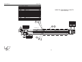
1
Service Manual RL4 Vertical Mast Part No. 1266665 Rev A August 2015 Service Manual August 2015 Introduction Introduction Important Information Introduction Important Technical Publications Read, understand and obey the safety rules and operating instructions in the appropriate Operator's Manual on your machine before attempting any maintenance procedure. Terex has endeavored to deliver the highest degree of accuracy possible. However, continuous improvement of our products is a Terex policy. Therefore, product specifications are subject to change without notice. This manual provides detailed scheduled maintenance information for the machine owner and user. It also provides troubleshooting and repair procedures for qualified service professionals. Readers are encouraged to notify Terex of errors and send in suggestions for improvement. All communications will be carefully considered for future printings of this and all other manuals. Basic mechanical, hydraulic and electrical skills are required to perform most procedures. However, several procedures require specialized skills, tools, lifting equipment and a suitable workshop. In these instances, we strongly recommend that maintenance and repair be performed at an authorized Terex dealer service center. Contact Us: Internet: www.genielift.com E-mail: [email protected] Compliance Machine Classification Group A/Type 1 as defined by ISO 16368 Machine Design Life Unrestricted with proper operation, inspection and scheduled maintenance. Copyright © 2015 by Terex Corporation 1266665 Rev A, August 2015 First Edition, First Printing 'Terex' and 'AWP' are registered trademarks of Terex USA, LLC in the U.S.A. and many other countries. ii RL4 Vertical Mast Part No. 1266665 August 2015 Service Manual Introduction Serial Number Legend Serial Number Legend MODEL: RL4 SERIAL NUMBER : RL4 15-105 MANUFACTURE DATE: 07/14/15 MODEL YEAR: 2015 ELECTRICAL SCHEMATIC NUMBER: Es0528 MACHINE UNLADEN WEIGHT: 1208 lbs / 548 kg AXLE WEIGHT : 3500 lbs / 1588 kg TONGUE WEIGHT : 100 lbs / 50 kg RL4 15 - 105 TIRE PRESSURE : 50 psi / 345 kPA MAXIMUM TOW SPEED : Position 50 KVA: HZ : 60 Hz KW: VOLTS : 48V RPM : MAX AMPS : Model Sequence number Model year MAX AMBIENT TEMPERA TURE : 104 F / 40 C INSULATION SYSTEM : Class F Country of manufacture: USA Manufacturer: Terex USA, LLC 590 Huey Road PO Box 3147 Rock Hill, SC 29732 USA Serial label Serial number (stamped on chassis) 1 2 3 4 5 Model Model year Sequence number Serial label (located on cabinet) Serial number (stamped on chassis) Part No. 1266665 RL4 Vertical Mast iii Service Manual August 2015 Safety Rules Section 1 General Safety Rules Safety Rules Danger Failure to obey the instructions and safety rules in this manual and the appropriate Operator's Manual on your machine will result in death or serious injury. Many of the hazards identified in the operator's manual are also safety hazards when maintenance and repair procedures are performed. Do Not Perform Maintenance Unless: You are trained and qualified to perform maintenance on this machine. You read, understand and obey: manufacturer's instructions and safety rules employer's safety rules and worksite regulations applicable governmental regulations You have the appropriate tools, lifting equipment and a suitable workshop. iv RL4 Vertical Mast Part No. 1266665 August 2015 Service Manual Safety Rules Workplace Safety Personal Safety Any person working on or around a machine must be aware of all known safety hazards. Personal safety and the continued safe operation of the machine should be your top priority. Any person working on or around a machine must be aware of all known safety hazards. Personal safety and the continued safe operation of the machine should be your top priority. Read each procedure thoroughly. This manual and the decals on the machine, use signal words to identify the following: Safety alert symbol–used to alert personnel to potential personal injury hazards. Obey all safety messages that follow this symbol to avoid possible injury or death. DANGER Indicates a imminently hazardous situation which, if not avoided, will result in death or serious injury. Be sure to keep sparks, flames and lighted tobacco away from flammable and combustible materials like battery gases and engine fuels. Always have an approved fire extinguisher within easy reach. Be sure that all tools and working areas are properly maintained and ready for use. Keep work surfaces clean and free of debris that could get into machine components and cause damage. WARNING Indicates a potentially hazardous situation which, if not avoided, could result in death or serious injury. Be sure any forklift, overhead crane or other lifting or supporting device is fully capable of supporting and stabilizing the weight to be lifted. Use only chains or straps that are in good condition and of ample capacity. CAUTION Indicates a potentially hazardous situation which, if not avoided, may cause minor or moderate injury. Be sure that fasteners intended for one time use (i.e., cotter pins and self-locking nuts) are not reused. These components may fail if they are used a second time. NOTICE Indicates a potentially hazardous situation which, if not avoided, may result in property damage. Be sure to properly dispose of old oil or other fluids. Use an approved container. Please be environmentally safe. Be sure to wear protective eye wear and other protective clothing if the situation warrants it. Be sure that your workshop or work area is properly ventilated and well lit. Be aware of potential crushing hazards such as moving parts, free swinging or unsecured components when lifting or placing loads. Always wear approved steel-toed shoes. Part No. 1266665 RL4 Vertical Mast v August 2015 Table of Contents Introduction Introduction .......................................................................................................... ii Important Information ..............................................................................................ii Serial Number Legend ........................................................................................... iii Serial Number Legend ........................................................................................... iii Section 1 Safety Rules......................................................................................................... iv General Safety Rules .............................................................................................iv Section 2 Specifications ....................................................................................................... 1 Machine Specifications .......................................................................................... 1 Performance Specifications ................................................................................... 1 Performance Specifications ................................................................................... 1 Machine Specifications .......................................................................................... 1 Machine Specifications .......................................................................................... 2 Machine Torque Specifications .............................................................................. 4 SAE and Metric Fasteners Torque Charts ............................................................. 5 Section 3 Scheduled Maintenance Procedures ................................................................. 7 Introduction ............................................................................................................ 7 Pre-Delivery Preparation Report .......................................................................... 10 Maintenance Inspection Report ........................................................................... 11 vi RL4 Vertical Mast Part No. 1266665 August 2015 Table of Contents Checklist A Procedures ..................................................................................... 13 A-1 Inspect the Manuals and Decals ................................................................... 13 A-2 Perform Pre-operation Inspection .................................................................. 14 A-3 Perform Function Tests ................................................................................. 14 A-4 Perform Engine Maintenance ........................................................................ 15 A-5 Perform Coupler Maintenance ....................................................................... 15 A-6 Test the Brakes (if equipped)......................................................................... 16 A-7 Torque the Wheel Lug Nuts ........................................................................... 16 A-8 Check the Tires and Wheels.......................................................................... 17 A-9 Inspect the Engine Air Filter........................................................................... 17 A-10 Perform Generator Maintenance ................................................................. 18 A-11 Perform Engine Maintenance ...................................................................... 19 A-12 Perform Engine Maintenance ...................................................................... 19 A-13 Inspect the Cable and Cable Pulleys........................................................... 20 A-14 Perform Engine Maintenance ...................................................................... 21 A-15 Perform Engine Maintenance ...................................................................... 21 A-16 Perform Generator Maintenance ................................................................. 22 A-17 Drain the Fuel Filter/Water Separator .......................................................... 22 A-18 Adjust the Brakes (if equipped) ................................................................... 24 Checklist B Procedures ..................................................................................... 25 B-1 Inspect the Engine Start Battery .................................................................... 25 B-2 Inspect the Electrical Wiring .......................................................................... 26 B-3 Torque the Wheel Lug Nuts ........................................................................... 27 B-4 Perform Engine Maintenance ........................................................................ 27 B-5 Perform Jack Maintenance ............................................................................ 28 B-6 Inspect and Lubricate the Winch ................................................................... 28 B-7 Lubricate the T-bolt ........................................................................................ 29 B-8 Inspect and Adjust the Brakes (if equipped) .................................................. 29 B-9 Inspect the Suspension ................................................................................. 31 B-10 Perform Engine Maintenance ...................................................................... 32 Part No. 1266665 RL4 Vertical Mast vii August 2015 Table of Contents Checklist C Procedures..................................................................................... 33 C-1 Perform Engine Maintenance........................................................................ 33 C-2 Clean the Light Assemblies........................................................................... 34 C-3 Grease the Wheel Bearings .......................................................................... 34 C-4 Inspect the Electric Brake Magnets .............................................................. 36 C-5 Perform Engine Maintenance........................................................................ 37 C-6 Perform Generator Maintenance................................................................... 38 Checklist D Procedures..................................................................................... 39 D-1 Perform Engine Maintenance........................................................................ 39 D-2 Perform Generator Maintenance................................................................... 40 D-3 Perform Coupler Maintenance ...................................................................... 40 Checklist E Procedures ..................................................................................... 41 E-1 Inspect the Cable and Cable Pulleys ............................................................ 41 E-2 Perform Engine Maintenance ........................................................................ 42 E-3 Perform Engine Maintenance ........................................................................ 43 E-4 Perform Generator Maintenance ................................................................... 43 E-5 Perform Generator Maintenance ................................................................... 44 E-6 Perform Generator Maintenance ................................................................... 44 Section 4 Repair Procedures ............................................................................................. 45 Introduction .......................................................................................................... 45 Lighting ............................................................................................................... 47 1-1 How to Remove a Lamp ................................................................................ 47 1-2 How to Check Line Voltage ........................................................................... 47 1-3 How to Check the Open Circuit Voltage ........................................................ 48 viii RL4 Vertical Mast Part No. 1266665 August 2015 Table of Contents Mast ..................................................................................................................... 49 2-1 How to Remove the Mast Assembly .............................................................. 49 2-2 How to Disassemble the Mast Assembly ....................................................... 49 2-3 How to Replace the Mast Lift Cables ............................................................. 51 2-4 How to Remove the Manual Winch ................................................................ 52 2-5 How to Remove the Electric Winch ................................................................ 53 Kohler KDW1003 Engine ................................................................................... 54 3-1 Timing Adjustment-Kohler Engines ................................................................ 54 3-2 Glow Plugs-Kohler Engines ........................................................................... 54 3-3 Coolant Temperature and Oil Pressure Switches-Kohler Engines ................ 54 Kubota D1105-E Engine ..................................................................................... 55 4-1 Timing Adjustment-Kubota Engines ............................................................... 55 4-2 Glow Plugs-Kubota Engines .......................................................................... 55 4-3 Coolant Temperature and Oil Pressure Switches-Kubota Engines ............... 55 Generator ............................................................................................................ 56 5-1 Generator ....................................................................................................... 56 5-2 How to Check a Generator Capacitor ............................................................ 57 5-3 How to Check a Generator Diode .................................................................. 57 Light Ballast ........................................................................................................ 59 6-1 Ground Controls ............................................................................................. 59 6-2 Light Ballast .................................................................................................... 60 Fuel Tank ............................................................................................................. 61 7-1 Fuel Tank ....................................................................................................... 61 Part No. 1266665 RL4 Vertical Mast ix August 2015 Table of Contents Section 5 Diagnostics ......................................................................................................... 62 Introduction .......................................................................................................... 62 Section 6 Schematics ......................................................................................................... 68 Introduction .......................................................................................................... 68 Wire Color Legend ............................................................................................... 69 RL4 Control Box AC Voltage Wiring - Standard .................................................. 71 RL4 Control Box AC Voltage Wiring - Standard .................................................. 72 RL4 Control Box AC Voltage Wiring - Autostart .................................................. 73 RL4 Control Box AC Voltage Wiring - Autostart .................................................. 74 RL4 DC Control Box - Standard........................................................................... 75 RL4 DC Control Box - Standard........................................................................... 76 RL4 DC Engine Components - DynaGen Autostart............................................. 77 RL4 DC Engine Components - DynaGen Autostart............................................. 78 RL4 DC Engine Components - Kohler ................................................................. 79 RL4 DC Engine Components - Kohler ................................................................. 80 RL4 DC Engine Components - Kubota ................................................................ 81 RL4 DC Engine Components - Kubota ................................................................ 82 RL4 DC Control Box - Timed Oil Switch .............................................................. 83 RL4 DC Control Box - Timed Oil Switch .............................................................. 84 RL4 DC Control Box - Low Fuel Shut Down ........................................................ 85 RL4 DC Control Box - Low Fuel Shut Down ........................................................ 86 RL4 Running Lights - Front Fairing Section ......................................................... 87 RL4 Running Lights - Front Fairing Section ......................................................... 88 RL4 Running Lights - Rear Fairing Section ......................................................... 89 RL4 Running Lights - Rear Fairing Section ......................................................... 90 RL4 Electrical Winch Option ................................................................................ 91 RL4 Electrical Winch Option ................................................................................ 92 x RL4 Vertical Mast Part No. 1266665 August 2015 Service Manual Specifications Section 2 Machine Specifications Specifications Performance Specifications Machine Specifications Total lighting wattage Generator Options 4 x 1000 watts 45 gallons 170 liters Single tank ST175/80D13 Load range Lug nut torque, dry Lug nut torque, lubricated C 90 ft-lbs 122 Nm 67.5 ft-lbs 91.5 Nm Performance Specifications Performance Specifications Generator rpm @ full load Temperature, ambient maximum 203 lbs 92 kg 110 hours For operational specifications, refer to the Operator's Manual. 6 kW 60 Hz, 1800 rpm 104° F 40° C Power 7 kW Coliseum 8 kW 1CBC08-TX Temperature, ambient maximum Run time 45 gallon tank 104° F 40° C Coliseum 7 kW 1CBC07-TX Generator rpm @ full load Tongue weight, maximum With fuel (45 gallon tank) Temperature, ambient maximum 60Hz, 1800 rpm Power Tires and wheels Tire size Coliseum 6 kW 1CBC06-TX Generator rpm @ full load Fuel capacities 60 Hz, 1800 rpm 104° F 40° C Power 8 kW For operational specifications, refer to the Operator's Manual. Continuous improvement of our products is a Genie policy. Product specifications are subject to change without notice or obligation. Continuous improvement of our products is a Genie policy. Product specifications are subject to change without notice or obligation. Machine Specifications Part No. 1266665 RL4 Vertical Mast 1 Service Manual August 2015 Specifications Kohler KDW1003 Engine Displacement Number of cylinders Bore and Stroke Oil pressure switch (engine shutoff pressure) 62.7 cu in 1.3 liters 3 2.95 x 3.1 inches 75 x 77.6 mm Horsepower 26.1 @ 3600 19.5 kW Firing order 1-2-3 Compression ratio Compression pressure Engine speed Governor Valve Clearance, cold 22.8:1 412 to 469 psi 28.4 to 32.3 bar 3600 rpm centrifugal mechanical 0.0057 to 0.0072 in 0.145 to 0.185 mm Engine coolant Capacity 1.37 quarts 1.3 liters Oil pressure Oil capacity (including filter) Oil viscosity requirements Unit ships with 10W-30. Extreme operating temperatures may require the use of alternative engine oils. For oil requirements, refer to the Engine Operator Manual for your engine. Injection system Injection pump Bosch MD mini Injection timing 19° BTDC Injection pump pressure, maximum 28 to 64 psi 1.93 to 4.41 bar 2.54 quarts 2.4 liters 1991 psi 137 bar Fuel requirement For fuel requirements, refer to the engine Operator Manual for your engine. Battery Type Group Quantity Cold cranking ampere Reserve capacity @ 75A rate Lubrication system 7 psi 12V DC 27TM 1 500 105 minutes Alternator Alternator output Fan belt deflection 40A, 12V DC 1/4 to 3/8 inch 7 to 9 mm Machine Specifications 2 RL4 Vertical Mast Part No. 1266665 August 2015 Service Manual Specifications Oil pressure switch (engine shutoff pressure) Kubota D1105-E Engine Displacement Number of cylinders Bore and Stroke 68.53 cu in 1.12 liters 3 3.07 x 3.09 inches 78 x 78.4 mm Horsepower 13.6 @ 1800 10.1 kW Firing order 1-2-3 Compression ratio Compression pressure Engine speed Governor Valve Clearance, cold 23:1 412 to 469 psi 28.4 to 32.3 bar 1800 rpm centrifugal mechanical 0.0057 to 0.0072 in 0.145 to 0.185 mm Capacity 3.27 quarts 3.1 liters Lubrication system Oil pressure Oil capacity (including filter) Part No. 1266665 Oil viscosity requirements Unit ships with 10W-30. Extreme operating temperatures may require the use of alternative engine oils. For oil requirements, refer to the Engine Operator Manual for your engine. Injection system Injection pump Bosch MD mini Injection timing 19° BTDC Injection pump pressure, maximum 1991 psi 137 bar Fuel requirement For fuel requirements, refer to the engine Operator Manual for your engine. Battery Type Group Quantity Engine coolant 7 psi Cold cranking ampere Reserve capacity @ 75A rate 12V DC 27TM 1 500 105 minutes Alternator 28 to 64 psi 1.93 to 4.41 bar 5.4 quarts 5.1 liters Alternator output Fan belt deflection RL4 Vertical Mast 40A, 12V DC 1/4 to 3/8 inch 7 to 9 mm 3 Service Manual August 2015 Specifications Machine Torque Specifications Machine Torque Specifications Generator Flex plate to flywheel 15 ft-lbs 20 Nm Generator case to bell housing 30 ft-lbs 41 Nm Generator isolators 75 ft-lbs 102 Nm Wheel lugs Lug nut torque, lubricated Lug nut torque, dry 67.5 ft-lbs 91.5 Nm 90 ft-lbs 122 Nm Engine vibration isolators Mounting bolts, dry 60 ft-lbs 81 Nm Mounting bolts, lubricated 45 ft-lbs 61 Nm Continuous improvement of our products is a Genie policy. Product specifications are subject to change without notice or obligation. 4 RL4 Vertical Mast Part No. 1266665 August 2015 Service Manual Specifications SAE and Metric Fasteners Torque Charts Part No. 1266665 RL4 Vertical Mast 5 Service Manual August 2015 Specifications This page intentionally left blank. 6 RL4 Vertical Mast Part No. 1266665 August 2015 Service Manual Scheduled Maintenance Procedures Section 3 Introduction Scheduled Maintenance Procedures Machine Configuration: Unless otherwise specified, perform each procedure with the machine in the following configuration: Machine parked on a firm, level surface Observe and Obey: Mast in the stowed position Maintenance inspections shall be completed by a person trained and qualified on the maintenance of this machine. Scheduled maintenance inspections shall be completed daily, quarterly, semi-annually, annually and every 2 years as specified of the Maintenance inspection Report. The frequency and extent of periodic examinations and tests may also depend on national regulations. WARNING Failure to perform each procedure as presented and scheduled may cause death, serious injury or substantial damage. Key switch in the off position with the key removed The red Emergency Stop button in the off position on the electrical control box Wheels chocked Light switches in the off position All external AC power supply disconnected from the machine Boom in the stowed position Turntable secured with the turntable rotation lock Immediately tag and remove from service a damaged or malfunctioning machine. Repair any machine damage or malfunction before operating the machine. Use only Terex approved replacement parts. Machines that have been out of service for a period longer than 3 months must complete the quarterly inspection. Part No. 1266665 RL4 Vertical Mast 7 Service Manual August 2015 Scheduled Maintenance Procedures About This Section This section contains detailed procedures for each scheduled maintenance inspection. Each procedure includes a description, safety warnings and step-by-step instructions. Symbols Legend Safety alert symbol–used to alert personnel to potential personal injury hazards. Obey all safety messages that follow this symbol to avoid possible injury or death. DANGER Indicates a imminently hazardous situation which, if not avoided, will result in death or serious injury. WARNING Indicates a potentially hazardous situation which, if not avoided, could result in death or serious injury. CAUTION Indicates a potentially hazardous situation which, if not avoided, may cause minor or moderate injury. NOTICE Indicates a potentially hazardous situation which, if not avoided, may result in property damage. Indicates that a specific result is expected after performing a series of steps. Indicates that an incorrect result has occurred after performing a series of steps. 8 RL4 Vertical Mast Part No. 1266665 August 2015 Service Manual Scheduled Maintenance Procedures Maintenance Symbols Legend Pre-delivery Preparation Report Note: The following symbols have been used in this manual to help communicate the intent of the instructions. When one or more of the symbols appear at the beginning of a maintenance procedure, it conveys the meaning below. The pre-delivery preparation report contains checklists for each type of scheduled inspection. Indicates that tools will be required to perform this procedure. Indicates that new parts will be required to perform this procedure. Make copies for each inspection. Store completed forms as required. Maintenance Schedule The Scheduled Maintenance Procedures section and the Maintenance Inspection Report have been divided into subsections. Use the following chart to determine which group(s) of procedures are required to perform a scheduled inspection. Inspection Indicates that dealer service will be required to perform this procedure. Checklist Daily or every 8 hours A Quarterly or every 250 hours A+B Semi-annually or every 500 hours Indicates that a cold engine will be required to perform this procedure. A+B+C Annually or every 1000 hours Two-year or every 2000 hours Indicates that a warm engine will be required to perform this procedure. A+B+C+D A+B+C+D+E Maintenance Inspection Report The maintenance inspection report contains checklists for each type of scheduled inspection. Make copies of the Maintenance Inspection Report to use for each inspection. Maintain completed forms for a minimum of 4 years or in compliance with your employer, jobsite and governmental regulations and requirements. Part No. 1266665 RL4 Vertical Mast 9 Service Manual August 2015 Pre-Delivery Preparation Report Pre-Delivery Preparation Report Fundamentals It is the responsibility of the dealer to perform the Pre-delivery Preparation. The Pre-delivery Preparation is performed prior to each delivery. The inspection is designed to discover if anything is apparently wrong with a machine before it is put into service. A damaged or modified machine must never be used. If damage or any variation from factory delivered condition is discovered, the machine must be tagged and removed from service. Repairs to the machine may only be made by a qualified service technician, according to the manufacturer's specifications. Scheduled maintenance inspections shall be performed by qualified service technicians, according to the manufacturer's specifications and the requirements listed in the responsibilities manual. Instructions Use the operator’s manual on your machine. The Pre-delivery Preparation consists of completing the Pre-operation Inspection, the Maintenance items and the Function Tests. Use this form to record the results. Place a check in the appropriate box after each part is completed. Follow the instructions in the operator’s manual. If any inspection receives an N, remove the machine from service, repair and re-inspect it. After repair, place a check in the R box. Legend Y = yes, acceptable N = no, remove from service R = repaired Comments Pre-delivery Preparation Pre-operation inspection completed Maintenance items completed Function tests completed Model Serial number Date Machine owner Inspected by (print) Inspector signature Inspector title Terex South Dakota, Inc USA 500 Oak Wood Road PO Box 1150 Watertown, SD 57201-6150 (605) 882-4000 Genie UK The Maltings, Wharf Road Grantham, Lincolnshire NG31- 6BH England (44) 1476-584333 Inspector company Y N R August 2015 Service Manual Maintenance Inspection Report Maintenance Inspection Report Model Checklist A A-1 Inspect the manuals and decals A-2 Pre-operation inspection A-3 Function tests Y N R Checklist B B-1 Batteries B-2 Electrical wiring B-3 Lug nuts B-4 Engine maintenance Perform after 8 hours: B-5 Jack A-4 B-6 Winch Perform before towing: B-7 T-bolt Inspected by (print) A-5 Coupler Perform every 3000 miles: Inspector signature A-6 Brakes (if equipped) B-8 Brakes (if equipped) Inspector title Perform after 10 miles: B-9 Suspension Inspector company A-7 Perform every 400 hours: Serial number Date Hour meter Engine maintenance Machine owner Lug nuts Perform weekly: Instructions Make copies of this report to use for each inspection. Select the appropriate checklist(s) for the type of inspection(s) to perform. Daily or every 8 hours Quarterly or every 250 hours Semi-annually or every 500 hours A A+B A+B+C A-8 Tires and wheels A-9 Engine air filter A-10 Generator maintenance A-11 Engine maintenance B-10 Y N R Engine maintenance Comments Perform after 50 hours: A-12 Engine maintenance Perform monthly: Annually or every 1000 hours A+B+C+D Two-year or every 2000 hours A+B+C+D+E A-13 Cables and pulleys Perform every 100 hours: Place a check in the appropriate box after each inspection procedure is completed. Use the step-by-step procedures in this section to learn how to perform these inspections. If any inspection receives an "N," tag and remove the machine from service, repair and re-inspect it. After repair, place a check in the "R" box. A-14 Engine maintenance Perform every 200 hours: A-15 Engine maintenance A-16 Generator maintenance A-17 Fuel/Water separator A-18 Brakes (if equipped) Legend Y = yes, acceptable N = no, remove from service R = repaired Part No. 1266665 RL4 Vertical Mast 11 Service Manual August 2015 Maintenance Inspection Report Model Checklist C Serial number Date Hour meter Machine owner E-1 C-2 Lights Perform every 2000 hours: E-2 C-3 Wheel bearings Perform every 3000 hours: C-4 Brakes (if equipped) E-3 Engine maintenance Perform every 10,000 hours: C-5 E-4 Inspector title Engine maintenance E-5 Y N R Perform every 1500 hours: Instructions D-1 Make copies of this report to use for each inspection. Select the appropriate checklist(s) for the type of inspection(s) to perform. Perform every 8000 hours: D-2 Generator maintenance Perform every 20,000 hours: Generator maintenance Checklist D Semi-annually or every 500 hours Engine maintenance Perform every 800 hours: C-6 Quarterly or every 250 hours Cable Perform every 6000 miles: Inspector signature A Y N R Engine maintenance Perform every 2000 hours: Daily or every 8 hours Checklist E C-1 Inspected by (print) Inspector company Y N R Engine maintenance Generator maintenance Generator maintenance Perform every 30,000 hours: E-6 Generator maintenance Comments Perform annually: D-3 Coupler A+B A+B+C Annually or every 1000 hours A+B+C+D Two-year or every 2000 hours A+B+C+D+E Place a check in the appropriate box after each inspection procedure is completed. Use the step-by-step procedures in this section to learn how to perform these inspections. If any inspection receives an "N," tag and remove the machine from service, repair and re-inspect it. After repair, place a check in the "R" box. Legend Y = yes, acceptable N = no, remove from service R = repaired 12 RL4 Vertical Mast Part No. 1266665 August 2015 Service Manual Checklist A Procedures Checklist A Procedures A-1 Inspect the Manuals and Decals A-1 Inspect the Manuals and Decals 2 Result: The operator's manual is appropriate for the machine and all manuals are legible and in good condition. Result: The operator's manual is not appropriate for the machine or all manuals are not in good condition or is illegible. Remove the machine from service until the manual is replaced. Terex specifications require that this procedure be performed every 8 hours or daily, whichever comes first. Maintaining the operator’s and safety manuals in good condition is essential to safe machine operation. Manuals are included with each machine and should be stored in the container provided in the platform. An illegible or missing manual will not provide safety and operational information necessary for a safe operating condition. In addition, maintaining all of the safety and instructional decals in good condition is mandatory for safe machine operation. Decals alert operators and personnel to the many possible hazards associated with using this machine. They also provide users with operation and maintenance information. An illegible decal will fail to alert personnel of a procedure or hazard and could result in unsafe operating conditions. 1 Check to make sure that the operator's and safety manuals are present and complete in the storage container inside the cabinet. Part No. 1266665 Examine the pages of each manual to be sure that they are legible and in good condition. 3 Open the operator's manual to the decals inspection section. Carefully and thoroughly inspect all decals on the machine for legibility and damage. Result: The machine is equipped with all required decals, and all decals are legible and in good condition. Result: The machine is not equipped with all required decals, or one or more decals are illegible or in poor condition. Remove the machine from service until the decals are replaced. 4 Always return the manuals to the storage container after use. Note: Contact your authorized Terex distributor or Terex if replacement manuals or decals are needed. RL4 Vertical Mast 13 Service Manual August 2015 Checklist A Procedures A-2 Perform Pre-operation Inspection A-3 Perform Function Tests A-2 Perform Pre-operation Inspection A-3 Perform Function Tests Terex specifications require that this procedure be performed every 8 hours or daily, whichever comes first. Terex specifications require that this procedure be performed every 8 hours or daily, whichever comes first. Completing a Pre-operation Inspection is essential to safe machine operation. The Pre-operation Inspection is a visual inspection performed by the operator prior to each work shift. The inspection is designed to discover if anything is apparently wrong with a machine before the operator performs the function tests. The Pre-operation Inspection also serves to determine if routine maintenance procedures are required. Completing the function tests is essential to safe machine operation. Function tests are designed to discover any malfunctions before the machine is put into service. A malfunctioning machine must never be used. If malfunctions are discovered, the machine must be tagged and removed from service. Complete information to perform this procedure is available in the appropriate operator's manual. Refer to the Operator's Manual on your machine. 14 Complete information to perform this procedure is available in the appropriate operator's manual. Refer to the Operator's Manual on your machine. RL4 Vertical Mast Part No. 1266665 August 2015 Service Manual Checklist A Procedures A-4 Perform Engine Maintenance A-5 Perform Coupler Maintenance A-4 Perform Engine Maintenance A-5 Perform Coupler Maintenance Engine specifications require that this procedure be performed every 8 hours or daily, whichever comes first. Coupler specifications require that this procedure be performed before towing. Engine oil level — check Coolant level — check/add Fuel system filter/water separator — drain Engine tightness — check for leaks Maintaining the coupler in good condition is essential to safe operation and good performance. Coupler failure could result in a machine tip-over during transport, and component damage may also result if problems are not discovered and repaired in a timely fashion. 1 Exhaust system — check for leaks Loose or missing fasteners Required maintenance procedures and additional engine information is available in the Kubota D1105-E and V1505-E Operator's Manual (Kubota 16683-89169 part number ) OR the Kohler KDW1003 Engine Owner's Manual (Kohler part number ED0053028440). Result: if coupler and/or mounting bracket is deformed or damaged, replace complete coupler and mounting bracket. Replace bent, broken or worn parts before use. 2 Close coupler securely by ensuring that the hitch ball is fully seated in the coupler ball pocket and the pin is inserted behind the collar or latch. 3 Check mounting bracket hardware for wear and proper tightness. Kohler KDW1003 Engine Owner's Manual Genie part number 1268769 Kubota D-1105 and V-1505 Operator's Manual Genie part number 893020 Check vehicle, mounting bracket, hitch ball and coupler for signs of wear or damage and that the coupler handle opens and closes freely. Result: Replace bent, broken or worn hardware. Part No. 1266665 RL4 Vertical Mast 15 Service Manual August 2015 Checklist A Procedures A-6 Test the Brakes (if equipped) A-7 Torque the Wheel Lug Nuts A-6 Test the Brakes (if equipped) A-7 Torque the Wheel Lug Nuts Axle specifications require that this procedure be performed before towing. Axle specifications require that this procedure be performed initially at 10, 25 and 50 miles of use, or after reinstallation of a tire. Maintaining the axle brakes in good condition is essential to safe operation and good performance. Brakes which are out of adjustment can result in longer stopping distances and excessive brake wear on the towing vehicle. Component damage may also result if problems are not discovered and repaired in a timely fashion. Maintaining the wheel lug nuts at proper torque is essential to safe operation and good service life of the tires, wheel and axle. 1 Check each lug nut for proper torque. Refer to Specifications, Machine Specifications. Test the brakes for proper function. Repair or replace any faulty components as needed. 16 RL4 Vertical Mast Part No. 1266665 August 2015 Service Manual Checklist A Procedures A-8 Check the Tires and Wheels A-9 Inspect the Engine Air Filter A-8 Check the Tires and Wheels A-9 Inspect the Engine Air Filter Axle specifications require that this procedure be performed weekly. Terex specifications require that this procedure be performed every 40 hours or weekly, whichever comes first. Maintaining the tires and wheels in good condition and the tires at the correct pressure is essential to safe operation and good performance. Tire and/or wheel failure could result in a machine tip-over. Component damage may also result if problems are not discovered and repaired in a timely fashion. Maintaining the engine air filter in good condition is essential to good engine performance and service life. Failure to perform this procedure can lead to poor engine performance and component damage. Note: Perform this procedure with the engine off. Open the engine side cover. Empty the dust discharge valve by pressing together the sides of the discharge slot. Clean the discharge slot as needed. 1 WARNING Bodily injury hazard. An over-inflated tire can explode and could cause death or serious injury. WARNING Tip-over hazard. Do not use temporary flat tire repair products. 1 1 Check tire surface and sidewalls for cuts, cracks, punctures and unusual wear. 2 2 Check each wheel for damage, bends and cracks. 3 Check the pressure in each air-filled tire. Refer to Specifications, Machine Specifications. 3 1 clamp 2 cannister end cap 3 dust discharge valve Part No. 1266665 RL4 Vertical Mast 17 Service Manual August 2015 Checklist A Procedures A-10 Perform Generator Maintenance 2 Release the latches on the air cleaner cap. Remove the end cap from the air cleaner canister. 3 Remove the filter element. 4 Use a damp cloth to wipe the filter sealing surface and the inside of the outlet tube. Make sure that all contaminant is removed before the filter is inserted. 5 Check new filter element gasket for damage before installing. 6 Install the new filter element. 7 Install the end cap on the canister and secure. Note: Be sure the discharge slot is pointing down. A-10 Perform Generator Maintenance Generator specifications require that this procedure be performed every 40 hours or weekly, whichever comes first. Clean and inspect the generator exterior Clean and replace the generator air filters (if equipped) Coliseum Manual Genie part number 18 RL4 Vertical Mast 1268770 Part No. 1266665 August 2015 Service Manual Checklist A Procedures A-11 Perform Engine Maintenance A-12 Perform Engine Maintenance A-11 Perform Engine Maintenance A-12 Perform Engine Maintenance Engine specifications require that this procedure be performed every 100 hours. Engine specifications require that this procedure be performed every 200 hours. Check fuel lines and clamps Change engine oil Required maintenance procedures and additional engine information is available in the Kubota D1105-E and V1505-E Operator's Manual (Kubota 16683-89169 part number ) OR the Kohler KDW1003 Engine Owner's Manual (Kohler part number ED0053028440). Kohler KDW1003 Engine Owner's Manual Genie part number 1268769 Kubota D-1105 and V-1505 Operator's Manual Genie part number Replace oil filter Required maintenance procedures and additional engine information is available in the Kubota D1105-E and V1505-E Operator's Manual (Kubota 16683-89169 part number ) OR the Kohler KDW1003 Engine Owner's Manual (Kohler part number ED0053028440). Kohler KDW1003 Engine Owner's Manual Genie part number 893020 Genie part number Part No. 1266665 1268769 Kubota D-1105 and V-1505 Operator's Manual RL4 Vertical Mast 893020 19 Service Manual August 2015 Checklist A Procedures A-13 Inspect the Cable and Cable Pulleys 5 A-13 Inspect the Cables and Cable Pulleys Visually inspect the winch cable for the following: nicks (partial strand cut through) kinks in the cable (permanent bends) weld splatter Result: Nicks, kinks in the cable or weld splatter are. The cable must immediately be replaced. Terex specifications require that this procedure be performed monthly. Detection of damage to the cables or pulleys is essential for safe machine operation. An unsafe working condition exists if these components are damaged and do not operate smoothly. Regular inspection of this system allows the inspector to identify changes in the operating condition that may indicate damage. 1 6 crushed spot on the cable Result: A crushed spot on the cable measuring 125% of the cable diameter or more is found OR there is a broken wire at the crush point. The cable must immediately be replaced. Visually inspect the electric winch and cable pulleys for the following: broken or damaged pulleys 7 unusual or excessive pulley wear Visually inspect the winch cable for the following: Wind cable onto the winch, ensuring that the cable is correctly installed onto each of the pulleys. Result: A pulley is broken or damaged, or shows unusual or excessive pulley wear. The pulley must immediately be replaced. 2 Put on protective leather gloves and eye wear. 3 Fully unwind the cable from the winch. 4 Wearing leather gloves, run a hand up and down a length of the cable, inspecting the cable and components for the following: frayed or broken wire strands Result: In any given one-foot of cable length there are 4 or more broken wires on any 2 or more strands. The cable must immediately be replaced. 20 RL4 Vertical Mast Part No. 1266665 August 2015 Service Manual Checklist A Procedures A-14 Perform Engine Maintenance A-15 Perform Engine Maintenance A-14 Perform Engine Maintenance A-15 Perform Engine Maintenance Engine specifications require that this procedure be performed every 100 hours. Engine specifications require that this procedure be performed every 200 hours. Clean air filter Change engine oil Clean the fuel filter Replace oil filter Inspect fan belt Inspect radiator hoses and clamps Required maintenance procedures and additional engine information is available in the Kubota D1105-E and V1505-E Operator's Manual (Kubota 16683-89169 part number ) OR the Kohler KDW1003 Engine Owner's Manual (Kohler part number ED0053028440). Kohler KDW1003 Engine Owner's Manual Genie part number 1268769 Kubota D-1105 and V-1505 Operator's Manual Genie part number Inspect air intake hose Required maintenance procedures and additional engine information is available in the Kubota D1105-E and V1505-E Operator's Manual (Kubota 16683-89169 part number ) OR the Kohler KDW1003 Engine Owner's Manual (Kohler part number ED0053028440). Kohler KDW1003 Engine Owner's Manual Genie part number 893020 Genie part number Part No. 1266665 1268769 Kubota D-1105 and V-1505 Operator's Manual RL4 Vertical Mast 893020 21 Service Manual August 2015 Checklist A Procedures A-16 Perform Generator Maintenance A-17 Drain the Fuel Filter/Water Separator A-16 Perform Generator Maintenance A-17 Drain the Fuel Filter/Water Separator Terex specifications require that this procedure be performed every 200 hours or monthly, whichever comes first. Generator specifications require that this procedure be performed every 200 hours or quarterly, whichever comes first. Clean and inspect the generator exterior Check for loose or damaged wires and components. WARNING Proper maintenance of the fuel filter/water separator is essential for good engine performance. Failure to perform this procedure can lead to poor engine performance and component damage. DANGER Electrocution/burn hazard. Contact with electrically charged circuits could result in death or serious injury. Remove all rings, watches and other jewelry. Coliseum Manual Genie part number 1268770 1 Explosion and fire hazard. Engine fuels are combustible. Perform this procedure in an open, well-ventilated area away from heaters, sparks, flames and lighted tobacco. Always have an approved fire extinguisher within easy reach. Locate the fuel filter/water separator and loosen the vent plug located on the fuel filter/water separator head. a a generator 22 RL4 Vertical Mast Part No. 1266665 August 2015 Service Manual Checklist A Procedures 2 Loosen the drain plug located at the bottom of the bowl. Allow the water to drain into a suitable container until fuel starts to come out. Immediately tighten the drain plug. a b Bleed the fuel system: 5 Loosen the vent plug/screw located on the filter head. 6 Operate the hand primer until fuel, free of air, flows from the vent plug/screw. Tighten the vent plug/screw on the filter head. 7 Loosen the vent screw, located on top of the fuel injection pump. 8 Operate the hand primer until fuel, free of air, flows from the vent plug/screw. Tighten the vent plug/screw on the injection pump. 9 Clean up any fuel that may have spilled. c d e 10 Attempt to start the engine using the starter motor for a maximum of 15 seconds, resting the starter for 30 seconds before trying again. 11 Inspect the fuel filter/water separator for leaks. DANGER a b c d e 3 head bolt vent plug separator head filter bowl drain plug Tighten the vent plug and clean up any spills or wet surfaces. Note: If the fuel bowl is completely drained, you must prime, or bleed, the fuel filter/water separator before starting the engine. See step 5. 4 Start the engine from the electrical control panel and check the fuel filter/water separator for leaks. Part No. 1266665 Explosion and fire hazard. If a fuel leak is discovered, keep any additional personnel from entering the area and do not operate the machine. Repair the leak immediately. Note: Required maintenance procedures and additional engine information is available in the Kubota D1105-E and V1505-E Operator's Manual (Kubota 16683-89169 part number ) OR the Kohler KDW1003 Engine Owner's Manual (Kohler part number ED0053028440). Kohler KDW1003 Engine Owner's Manual Genie part number 1268769 Kubota D-1105 and V-1505 Operator's Manual Genie part number RL4 Vertical Mast 893020 23 Service Manual August 2015 Checklist A Procedures A-18 Adjust the Brakes (if equipped) 4 A-18 Test the Brakes (if equipped) Axle specifications require that this procedure be performed initially at 250 miles of use. Maintaining the axle brakes in good condition is essential to safe operation and good performance. Brakes which are out of adjustment can result in longer stopping distances and excessive brake wear on the towing vehicle. Component damage may also result if problems are not discovered and repaired in a timely fashion. Note: Perform this procedure with the machine on a firm, level surface with the machine in the stowed position. 1 Select a wheel. Chock the front and rear of the tire at the opposite side of the machine. 2 Place a lifting jack under the axle near the brake to be adjusted. Lift the axle until the wheel is off the ground and place a jack stand under the axle. Lower the axle onto the jack stand. 3 Working from the back side of the wheel at the brake backing plate, locate and remove the small rubber plug from the lower side of the backing plate to access the star-shaped brake adjuster wheel. Set the plug to the side. Insert a brake adjuster tool into the opening of the brake backing plate, engaging it with the teeth of the brake adjuster wheel. Move the tip of the adjuster tool in an upwards direction to tighten the brakes. Note: It may be helpful to use a flashlight when locating the brake adjuster wheel. 5 Repeatedly move the tip of the adjuster tool in an upwards direction to tighten the brakes until the wheel locks up and will no longer turn. Note: This centers the brake shoes on the brake drum, ensuring the shoes are positioned correctly. 6 Move the tip of the adjuster tool in a downwards direction 3 to 5 clicks to loosen the brakes only until the wheel spins freely with little drag. 7 Securely install the small rubber plaug into the brake backing plate. 8 Check the wheel bearing wear by attempting to move wheel hub side to side, then up and down. There is no side to side or up and down movement. The bearing is good. There is side to side or up and down movement. The bearing must be adjusted or replaced. See B-8, Inspect and Adjust the Brakes (if equipped). 9 Lift the axle slightly. Remove the jack stand and lower the machine to the ground. Chock the front and rear of the tire. 10 Repeat this procedure, beginning with step 2, for the other wheel. 24 RL4 Vertical Mast Part No. 1266665 August 2015 Service Manual Checklist B Procedures Checklist B Procedures B-1 Inspect the Engine Start Battery B-1 Inspect the Engine Start Battery Terex specifications require that this procedure be performed every 250 hours or quarterly, whichever comes first. Proper battery condition is essential to good engine performance and operational safety. Improper fluid levels or damaged cables and connections can result in engine component damage and hazardous conditions. WARNING WARNING Be sure that the battery retainers and cable connections are tight. 4 Be sure that the battery separator wire connections are tight (if equipped). Models without maintenance-free or sealed batteries: 5 Put on protective clothing and eye wear. 6 Remove the battery vent caps and check the specific gravity of each battery cell with a hydrometer. Note the results. 7 Check the ambient air temperature and adjust the specific gravity reading for each cell as follows: Electrocution/burn hazard. Contact with electrically charged circuits could result in death or serious injury. Remove all rings, watches and other jewelry. Add 0.004 to the reading of each cell for every 10° F / 5.5° C above 80° F / 26.7° C. Subtract 0.004 from the reading of each cell for every 10° F / 5.5° C below 80° F / 26.7° C. Bodily injury hazard. Batteries contain acid. Avoid spilling or contacting battery acid. Neutralize battery acid spills with baking soda and water. Note: Fully charge the batteries and allow the batteries to rest 24 hours before performing this procedure to allow the battery cells to equalize. 1 Open the side covers. 2 Be sure that the battery cable connections are free of corrosion. Note: Adding terminal protectors and a corrosion preventative sealant will help eliminate corrosion on the battery terminals and cables. Part No. 1266665 3 Result: All battery cells display an adjusted specific gravity of 1.277 or higher. The battery is fully charged. Proceed to step 11. Result: One or more battery cells display a specific gravity of 1.276 or below. Proceed to step 8. 8 Perform an equalizing charge OR fully charge the battery(s) and allow the battery(s) to rest at least 6 hours. 9 Remove the battery vent caps and check the specific gravity of each battery cell with a hydrometer. Note the results. RL4 Vertical Mast 25 Service Manual August 2015 Checklist B Procedures B-2 Inspect the Electrical Wiring 10 Check the ambient air temperature and adjust the specific gravity reading for each cell as follows: B-2 Inspect the Electrical Wiring Add 0.004 to the reading of each cell for every 10° F / 5.5° C above 80° F / 26.7° C. Subtract 0.004 from the reading of each cell for every 10° F / 5.5° C below 80° F / 26.7° C. Terex specifications require that this procedure be performed every 250 hours or quarterly, whichever comes first. Result: All battery cells display a specific gravity of 1.277 or greater. The battery is fully charged. Proceed to step 11. Maintaining electrical wiring in good condition is essential to safe operation and good machine performance. Failure to find and replace burnt, chafed, corroded or pinched wires could result in unsafe operating conditions and may cause component damage. Result: One or more battery cells display a specific gravity from 1.218 to 1.269. The battery is still usable, but at a lower performance. The battery will need to be recharged more often. Proceed to step 11. WARNING Result: One or more battery cells display a specific gravity from 1.217 to 1.173. The battery is approaching the end of it's life. Proceed to step 11. Result: The difference in specific gravity readings between cells is greater than 0.1 OR the specific gravity of one or more cells is less than 1.177. Replace the battery. 1 Inspect the following areas for burnt, chafed, corroded pinched and loose wires: Ground controls Battery 11 Check the battery acid level. If needed, replenish with distilled water to 1/8 inch / 3 mm below the bottom of the battery fill tube. Do not overfill. Engine Mast Lighting junction box 12 Install the vent caps and neutralize any electrolyte that may have spilled. 13 Close the side covers. Electrocution/burn hazard. Contact with electrically charged circuits could result in death or serious injury. Remove all rings, watches and other jewelry. Trailer lighting wire harness 2 Inspect for a liberal coating of dielectric grease in the following locations: Lighting junction box Ground controls All wire harness connectors 26 RL4 Vertical Mast Part No. 1266665 August 2015 Service Manual Checklist B Procedures B-3 Torque the Wheel Lug Nuts B-4 Perform Engine Maintenance B-3 Torque the Wheel Lug Nuts B-4 Perform Engine Maintenance Axle specifications require that this procedure be performed initially at 10, 25 and 50 miles of use, or after reinstallation of a tire. Engine specifications require that this procedure be performed every 250 hours or six months, whichever comes first. Maintaining the wheel lug nuts at proper torque is essential to safe operation and good service life of the tires, wheel and axle. 1 Check each lug nut for proper torque. Refer to Specifications, Machine Specifications. Inspect alternator and fan belts Required maintenance procedures and additional engine information is available in the Kubota D1105-E and V1505-E Operator's Manual (Kubota 16683-89169 part number ) OR the Kohler KDW1003 Engine Owner's Manual (Kohler part number ED0053028440). Kohler KDW1003 Engine Owner's Manual Genie part number 1268769 Kubota D-1105 and V-1505 Operator's Manual Genie part number Part No. 1266665 RL4 Vertical Mast 893020 27 Service Manual August 2015 Checklist B Procedures B-5 Perform Jack Maintenance B-6 Inspect and Lubricate the Winch B-5 Perform Jack Maintenance B-6 Inspect and Lubricate the Winch Jack specifications require that this procedure be performed every 250 hours or quarterly, whichever comes first. Terex specifications require that this procedure be performed every 250 hours or quarterly, whichever comes first. Maintaining the jack is essential to good machine performance and safe operation. An unsafe working condition exists if the jack has excessive wear and/or does not operate smoothly, free of hesitation and binding. Maintaining the winch is essential to good machine performance and safe operation. An unsafe working condition exists if the winch has excessive wear and/or does not operate smoothly, free of hesitation and binding. 1 Select a jack. 2 Remove the cover from the top of the jack. 3 Apply a small amount of automotive grease to the internal gearing, and rotate the handle several times to evenly distribute the grease. 4 Apply a few drops of light oil to the jack handle where it makes contact with the outside of the jack tube. 5 Securely install the cover onto the jack. 6 Repeat this procedure, beginning with step 1, for the other jackson the machine. 28 1 Carefully lubricate the winch. RL4 Vertical Mast Part No. 1266665 August 2015 Service Manual Checklist B Procedures B-7 Lubricate the T-bolt B-8 Inspect and Adjust the Brakes (if equipped) B-7 Lubricate the T-bolt B-8 Inspect and Adjust the Brakes (if equipped) Terex specifications require that this procedure be performed every 250 hours or quarterly, whichever comes first. Maintaining the T-bolt is essential to good machine performance and safe operation. An unsafe working condition exists if the T-bolt has excessive wear and/or does not operate smoothly, free of hesitation and binding. 1 Using the illustration as a guide, locate the T-bolt at the bottom of the mast assembly. Remove the T-bolt from the mast. 2 Remove all dust, dirt and oil residue from the threaded surfaces of the T-bolt, and apply a few drops of light oil or thread lubricant onto the threaded surfaces. 3 Fully install the T-bolt into the mast. Axle specifications require that this procedure be performed every 3000 miles or quarterly, whichever comes first. Maintaining the axle brakes in good condition is essential to safe operation and good performance. Brakes which are out of adjustment can result in longer stopping distances and excessive brake wear on the towing vehicle. Component damage may also result if problems are not discovered and repaired in a timely fashion. Note: Perform this procedure with the machine on a firm, level surface with the machine in the stowed position. 1 Select a wheel. Chock the front and rear of the tire at the opposite side of the machine. 2 Loosen the wheel lug nuts. Do not remove them. 3 Place a lifting jack under the axle near the wheel to be removed. Lift the axle until the wheel is off the ground and place a jack stand under the axle. Lower the axle onto the jack stand and remove the wheel. 4 Remove the dust cap from the hub. Remove the cotter pin from the castle nut. 5 Remove the castle nut and washer. 6 Pull the hub off of the spindle. The washer and outer bearing should fall loose from the hub. a a T-bolt Part No. 1266665 RL4 Vertical Mast 29 Service Manual August 2015 Checklist B Procedures 7 Inspect the brake lining for wear (if equipped). Result: the thickness of the brake lining is greater than 1/16 inch / 1.6 mm. The brake shoes are good. Result: the thickness of the brake lining is 1/16 inch / 1.6 mm or less. The brake shoes must be replaced and the brake drums must be inspected for wear, scoring and other damage. Note: The maximum bore of a good brake drum shall not be greater than 0.090 inch / 2.29 mm in excess of the drum diameter. Note: If drum resurfacing is required, the brake drum should be resurfaced to a 120 micron finish. Note: If replacing the brake shoes, apply a light coat of grease or anti-seize compound to the anchor pin, arm bushing and pin, and areas of the backing plate which contact the magnet arm and brake shoes frame. Apply a small amount of lube to the actuating cam at the top of the magnet arm. Do not allow grease or oil to contact the brakes shoes or the inside of the drum. 8 9 Component damage hazard. Do not apply excessive force or damage to the lip of the seal may occur. Place the outer bearing into the hub. 10 Install the washer and the castle nut. 11 Tighten the castle nut to 50 ft-lbs / 68 Nm to seat the bearings. 30 13 Finger tighten the castle nut until snug. 14 Install a new cotter pin. Bend the cotter pin to lock it in place. Note: Always replace the cotter pin with a new one when removing the castle nut. 15 Install the dust cap, then the tire and wheel assembly. Torque the wheel lug nuts to specification. Refer to Section 2, Specifications. 16 Working from the back side of the wheel at the brake backing plate, locate and remove the small rubber plug from the lower side of the backing plate to access the star-shaped brake adjuster wheel. Set the plug to the side. 17 Insert a brake adjuster tool into the opening of the brake backing plate, engaging it with the teeth of the brake adjuster wheel. Move the tip of the adjuster tool in an upwards direction to tighten the brakes. Note: It may be helpful to use a flashlight when locating the brake adjuster wheel. Slide the hub onto the yoke spindle. NOTICE 12 Fully loosen the castle nut. Do not rotate the hub. 18 Repeatedly move the tip of the adjuster tool in an upwards direction to tighten the brakes until the wheel locks up and will no longer turn. Note: This centers the brake shoes on the brake drum, ensuring the shoes are positioned correctly. 19 Move the tip of the adjuster tool in a downwards direction 3 to 5 clicks to loosen the brakes only until the wheel spins freely with little drag. RL4 Vertical Mast Part No. 1266665 August 2015 Service Manual Checklist B Procedures B-9 Inspect the Suspension 20 Securely install the small rubber plug into the brake backing plate. 21 Check the wheel bearing wear by attempting to move wheel hub side to side, then up and down. There is no side to side or up and down movement. The bearing is good. There is side to side or up and down movement. The bearing must be adjusted or replaced. See B-8, Inspect and Adjust the Brakes (if equipped). 22 Lift the axle slightly. Remove the jack stand and lower the machine to the ground. Chock the front and rear of the tire. 23 Repeat this procedure, beginning with step 2, for the other wheel. Part No. 1266665 B-9 Inspect the Suspension Axle specifications require that this procedure be performed every 3000 miles or quarterly, whichever comes first. Maintaining the axle suspension in good condition is essential to safe operation and good performance. Towing the machine with worn or damaged suspension components could result in a tip-over. Component damage may also result if problems are not discovered and repaired in a timely fashion. 1 Working with a flashlight or in a well lit shop, carefully inspect all suspension components and fasteners. Replace as necessary. RL4 Vertical Mast 31 Service Manual August 2015 Checklist B Procedures B-10 Perform Engine Maintenance B-10 Perform Engine Maintenance Engine specifications require that this procedure be performed every 400 hours or semi-annually, whichever comes first. Replace oil filter Replace fuel filter Required maintenance procedures and additional engine information is available in the Kubota D1105-E and V1505-E Operator's Manual (Kubota 16683-89169 part number ) OR the Kohler KDW1003 Engine Owner's Manual (Kohler part number ED0053028440). Kohler KDW1003 Engine Owner's Manual Genie part number 1268769 Kubota D-1105 and V-1505 Operator's Manual Genie part number 893020 32 RL4 Vertical Mast Part No. 1266665 August 2015 Service Manual Checklist C Procedures Checklist C Procedures C-1 Perform Engine Maintenance C-1 Perform Engine Maintenance Engine specifications require that this procedure be performed every 500 hours. Replace fan belts Flush coolant system Clean fuel tank Required maintenance procedures and additional engine information is available in the Kubota D1105-E and V1505-E Operator's Manual (Kubota 16683-89169 part number ) OR the Kohler KDW1003 Engine Owner's Manual (Kohler part number ED0053028440). Kohler KDW1003 Engine Owner's Manual Genie part number 1268769 Kubota D-1105 and V-1505 Operator's Manual Genie part number Part No. 1266665 RL4 Vertical Mast 893020 33 Service Manual August 2015 Checklist C Procedures C-2 Clean the Light Assemblies C-3 Grease the Wheel Bearings C-2 Clean the Light Assemblies C-3 Grease the Wheel Bearings Terex specifications require that this procedure be performed every 500 hours or semi-annually, whichever comes first. Axle specifications require that this procedure be performed every 6,000 hours or semi-annually, whichever comes first. Maintaining the light assemblies is essential to good machine performance. Failure to regularly clean the light assemblies may result in less light than expected and, over time, could result in damage to the machine. Maintaining the axle wheel bearings is essential to safe machine operation and service life. Operating a machine with loose or worn wheel bearings may cause an unsafe operating condition and continued use may result in component damage. Extremely wet or dry conditions or regular steam cleaning and pressure washing of the machine may require that this procedure be performed more often. Note: Perform this procedure with the light assemblies out of direct sunlight and cool to the touch. 1 Use clean, cool water to rinse the surface of each light assembly. Note: Perform this procedure with the machine on a firm, level surface with the machine in the stowed position. 2 Clean each light assembly using a soft cloth, water and a mild dishwashing detergent. 1 Select a wheel. Chock the front and rear of the tire at the opposite side of the machine. 2 Loosen the wheel lug nuts. Do not remove them. 3 Place a lifting jack under the axle near the wheel to be removed. Lift the axle until the wheel is off the ground and place a jack stand under the axle. Lower the axle onto the jack stand and remove the wheel. 4 Remove the dust cap from the hub. Remove the cotter pin from the castle nut. NOTICE 3 34 Component damage hazard. Harsh checmcals and cleaning agents will damage the surface of the light assembly. Do not allow harsh cleaning agents to make contact with the light surface.. Thoroughly rinse, then dry with a soft cloth. RL4 Vertical Mast Part No. 1266665 August 2015 Service Manual Checklist C Procedures 5 Remove the castle nut and washer. 6 Pull the hub off of the spindle. The washer and outer bearing should fall loose from the hub. 7 Place the hub on a flat surface and gently pry the bearing seal out of the hub. Remove the rear bearing. 8 Pack both bearings with clean, fresh grease. 9 Inspect the hub for wear. Replace if necessary. 16 Slide the hub onto the yoke spindle. NOTICE Component damage hazard. Do not apply excessive force or damage to the lip of the seal may occur. 17 Place the outer bearing into the hub. 18 Install the washer and the castle nut. 19 Tighten the castle nut to 50 ft-lbs / 68 Nm to seat the bearings. 10 Place the large inner bearing into the rear of the hub. 11 Install a new bearing grease seal into the hub by pressing it evenly into the hub until it is flush. Note: Always replace the bearing grease seal when removing the hub. 12 Inspect the brake lining for wear (if equipped). 13 Inspect the brake cylinder for leaks (if equipped). 14 Inspect the brake springs for wear or loss of arch (if equipped). 20 Fully loosen the castle nut. Do not rotate the hub. 21 Finger tighten the castle nut until snug. 22 Install a new cotter pin. Bend the cotter pin to lock it in place. Note: Always replace the cotter pin with a new one when removing the castle nut. 23 Install the dust cap, then the tire and wheel assembly. Torque the wheel lug nuts to specification. Refer to Section 2, Specifications. 15 Inspect the brake wiring/hoses for wear (if equipped). Part No. 1266665 RL4 Vertical Mast 35 Service Manual August 2015 Checklist C Procedures C-4 Inspect the Electric Brake Magnets 3 C-4 Inspect the Electric Brake Magnets (if equipped) Result: The total amp draw measures 5.5 to 6.0 amps. The brake circuit is functioning correctly. Axle specifications require that this procedure be performed every 6,000 hours or semi-annually, whichever comes first. Maintaining the axle brakes in good condition is essential to safe operation and good performance. A faulty brake magnet can severely impact the stopping power of a trailer. While some magnet problems will be apparent upon visual inspection, there may also be electrical problems that can impact performance. A failing or faulty brake magnet can lead to weak or surging brakes, or cause the brakes to pull to one side. It is important to inspect and test the magnets at regular intervals to ensure maximum effectiveness. 1 Connect the electric brake wire harness to a tow vehicle capable of towing the machine. 2 Start the engine of the tow vehicle, and press down on the brake pedal. Result: An audible 'click' is noted at each brake when the brake magnet is activated and pulls itself into contact with the brake drum. The brake circuit is functioning correctly. Result: An audible 'click' is not noted at each brake because the brake magnet is not activated and does not make contact with the brake drum. The brake circuit is faulty. Inspect the wire harness and harness connections and repair as required, and repeat this procedure beginning with step 2. 36 With the engine running, press down on the brake pedal and use a multimeter to measure the total amp draw of the brake circuit by positioning an amp clamp around the brake wire lead near the trailer connector. Note the reading. Result: The total amp draw measures less than 5.5 amps. Replace the magnets and magnet springs on both sides of the axle, and resurface the brake drums. Repeat this procedure beginning with step 4. 4 Stop the engine of the tow vehicle. 5 Select a wheel. Chock the front and rear of the tire at the opposite side of the machine. 6 Loosen the wheel lug nuts. Do not remove them. 7 Place a lifting jack under the axle near the wheel to be removed. Lift the axle until the wheel is off the ground and place a jack stand under the axle. Lower the axle onto the jack stand and remove the wheel. 8 Remove the dust cap from the hub. Remove the cotter pin from the castle nut. 9 Remove the castle nut and washer. 10 Pull the hub off of the spindle. The washer and outer bearing should fall loose from the hub. RL4 Vertical Mast Part No. 1266665 August 2015 Service Manual Checklist C Procedures C-5 Perform Engine Maintenance 11 Locate the brake magnet. Inspect the surface of the magnet for pitting and any irregular surface wear. Result: Replace the magnets and magnet springs on both sides of the axle if pitting or any irregular surface wear is detected, and resurface the brake drums. 12 Inspect the copper coil at the center of the magnet. Result: Replace the magnets and magnet springs on both sides of the axle if the exposed copper coil is visible in any way, and resurface the brake drums. 13 Slide the hub onto the yoke spindle. NOTICE Component damage hazard. Do not apply excessive force or damage to the lip of the seal may occur. C-5 Perform Engine Maintenance Engine specifications require that this procedure be performed every 800 hours or annually, whichever comes first. Replace air filter Inspect wiring Check valve clearance Required maintenance procedures and additional engine information is available in the Kubota D1105-E and V1505-E Operator's Manual (Kubota 16683-89169 part number ) OR the Kohler KDW1003 Engine Owner's Manual (Kohler part number ED0053028440). Kohler KDW1003 Engine Owner's Manual 14 Place the outer bearing into the hub. Genie part number 15 Install the washer and the castle nut. 1268769 Kubota D-1105 and V-1505 Operator's Manual 16 Tighten the castle nut to 50 ft-lbs / 68 Nm to seat the bearings. Genie part number 893020 17 Fully loosen the castle nut. Do not rotate the hub. 18 Finger tighten the castle nut until snug. 19 Install a new cotter pin. Bend the cotter pin to lock it in place. Note: Always replace the cotter pin with a new one when removing the castle nut. 20 Install the dust cap, then the tire and wheel assembly. Torque the wheel lug nuts to specification. Refer to Section 2, Specifications. 21 Repeat this procedure, beginning with step 6, for the other side of the machine. Part No. 1266665 RL4 Vertical Mast 37 Service Manual August 2015 Checklist C Procedures C-6 Perform Generator Maintenance C-6 Perform Generator Maintenance Generator specifications require that this procedure be performed every 2000 hours or semi-annually, whichever comes first. Maintaining the generator in good condition is essential to safe operation and long service life. Storing the generator in a harsh environment may require this procedure be performed more frequently. Loose or damaged connections or components may result in a generator to lose efficiency, and reduce the life of the generator. Inspect stator output leads and insulation for cracking and damage. Inspect exposed electrical for loose or damaged connections. Inspect transformers, fuses, capacitors and lighting arrestors for loose or damaged component connections. Inspect all wire and electrical connections for proper clearance.. Inspect and clean inside of outlet box, air screens and air baffles with compressed air. Inspect for machine vibration and bearing wear. Coliseum Manual Genie part number 38 1268770 RL4 Vertical Mast Part No. 1266665 August 2015 Service Manual Checklist D Procedures Checklist D Procedures D-1 Perform Engine Maintenance D-1 Perform Engine Maintenance Engine specifications require that this procedure be performed every 1500 hours or bi-annually, whichever comes first. Injectors Required maintenance procedures and additional engine information is available in the Kubota D1105-E and V1505-E Operator's Manual (Kubota 16683-89169 part number ) OR the Kohler KDW1003 Engine Owner's Manual (Kohler part number ED0053028440). Kohler KDW1003 Engine Owner's Manual Genie part number 1268769 Kubota D-1105 and V-1505 Operator's Manual Genie part number Part No. 1266665 RL4 Vertical Mast 893020 39 Service Manual August 2015 Checklist D Procedures D-2 Perform Generator Maintenance D-3 Perform Coupler Maintenance D-2 Perform Generator Maintenance D-3 Perform Coupler Maintenance Generator specifications require that this procedure be performed every 8000 hours or annually, whichever comes first. Coupler specifications require that this procedure be performed annually. Maintaining the generator in good condition is essential to safe operation and long service life. Storing the generator in a harsh environment may require this procedure be performed more frequently. Poor resistance may result in a generator to lose efficiency, and reduce the life of the generator. Maintaining the coupler in good condition is essential to safe operation and good performance. Coupler failure could result in a machine tip-over during transport, and component damage may also result if problems are not discovered and repaired in a timely fashion. 1 Check resistance to ground on generator windings, main rotating assembly, stator, exciter field and armature. Coliseum Manual Genie part number 40 Check coupler welds and mounting bolt torque. Torque the fasteners to 35 ft-lbs / 48 Nm. Result: 1.5 full threads of the locking bolt must be exposed beyond the lock nut after the adjustment. 2 Apply automotive grease to the coupler ball pocket. 3 Oil coupler pivot points using SAE 30 motor oil. 1268770 RL4 Vertical Mast Part No. 1266665 August 2015 Service Manual Checklist E Procedures Checklist E Procedures E-1 Inspect the Cable and Cable Pulleys E-1 Inspect the Cables and Cable Pulleys Terex specifications require that this procedure be performed every two years. Detection of damage to the cables or pulleys is essential for safe machine operation. An unsafe working condition exists if these components are damaged and do not operate smoothly. Regular inspection of this system allows the inspector to identify changes in the operating condition that may indicate damage. 1 Visually inspect the electric winch and cable pulleys for the following: broken or damaged pulleys unusual or excessive pulley wear Result: A pulley is broken or damaged, or shows unusual or excessive pulley wear. The pulley must immediately be replaced. 2 Put on protective leather gloves and eye wear. 3 Fully unwind the cable from the winch. 4 Wearing leather gloves, run a hand up and down a length of the cable, inspecting the cable and components for the following: frayed or broken wire strands Result: In any given one-foot of cable length there are 4 or more broken wires on any 2 or more strands. The cable must immediately be replaced. Part No. 1266665 RL4 Vertical Mast 41 Service Manual August 2015 Checklist E Procedures E-2 Perform Engine Maintenance 5 Visually inspect the winch cable for the following: E-2 Perform Engine Maintenance nicks (partial strand cut through) kinks in the cable (permanent bends) weld splatter Result: Nicks, kinks in the cable or weld splatter are. The cable must immediately be replaced. 6 Replace coolant Visually inspect the winch cable for the following: Replace radiator hoses and clamps crushed spot on the cable Replace fuel hoses and clamps Result: A crushed spot on the cable measuring 125% of the cable diameter or more is found OR there is a broken wire at the crush point. The cable must immediately be replaced. 7 Engine specifications require that this procedure be performed every 2000 hours or bi-annually, whichever comes first. Wind cable onto the winch, ensuring that the cable is correctly installed onto each of the pulleys. If the mast cables need replacing, refer to Repair Procedure 1-1, How to Replace the Mast Lift Cables. Replace air intake hose and clamps Required maintenance procedures and additional engine information is available in the Kubota D1105-E and V1505-E Operator's Manual (Kubota 16683-89169 part number ) OR the Kohler KDW1003 Engine Owner's Manual (Kohler part number ED0053028440). Kohler KDW1003 Engine Owner's Manual Genie part number Genie part number 42 1268769 Kubota D-1105 and V-1505 Operator's Manual RL4 Vertical Mast 893020 Part No. 1266665 August 2015 Service Manual Checklist E Procedures E-3 Perform Engine Maintenance E-4 Perform Generator Maintenance E-3 Perform Engine Maintenance E-4 Perform Generator Maintenance Engine specifications require that this procedure be performed every 3000 hours. Generator specifications require that this procedure be performed every 10,000 hours. Inspect injection pump Inspect injection timing Required maintenance procedures and additional engine information is available in the Kubota D1105-E and V1505-E Operator's Manual (Kubota 16683-89169 part number ) OR the Kohler KDW1003 Engine Owner's Manual (Kohler part number ED0053028440). Replace the generator shaft bearing. Consult a trained Coliseum service professional. Coliseum Manual Kohler KDW1003 Engine Owner's Manual Genie part number Maintaining the generator in good condition is essential to safe operation and long service life. Regular replacement of the shaft bearing will extend the life of the generator. 1268769 Genie part number 1268770 Kubota D-1105 and V-1505 Operator's Manual Genie part number 893020 Part No. 1266665 RL4 Vertical Mast 43 Service Manual August 2015 Checklist E Procedures E-5 Perform Generator Maintenance E-6 Perform Generator Maintenance E-5 Perform Generator Maintenance E-6 Perform Generator Maintenance Generator specifications require that this procedure be performed every 20,000 hours or 3 years, whichever comes first. Generator specifications require that this procedure be performed every 30,000 hours or 5 years, whichever comes first. Maintaining the generator in good condition is essential to safe operation and long service life. Storing the generator in a harsh environment may require this procedure be performed more frequently. Allowing dirt and grease to build up on the generator may result in a generator which will run hotter, lose efficiency, and reduce the life of the generator. Maintaining the generator in good condition is essential to safe operation and long service life. Storing the generator in a harsh environment may require this procedure be performed more frequently. Allowing dirt and grease to build up on the generator may result in a generator which will run hotter, lose efficiency, and reduce the life of the generator. Regular replacement of the shaft bearing will extend the service life of the generator. Inspect and clean the generator and windings for oil or dirt contamination. Disassemble the generator, including rotor removal. Coliseum Manual Genie part number 1268770 Inspect and clean generator components including generator windings. Replace the generator shaft bearings. Consult a trained Coliseum service professional. Coliseum Manual Genie part number 44 RL4 Vertical Mast 1268770 Part No. 1266665 August 2015 Service Manual Repair Procedures Section 4 Introduction Repair Procedures Machine Configuration: Unless otherwise specified, perform each repair procedure with the machine in the following configuration: Machine parked on a firm, level surface Observe and Obey: Mast in the stowed position Repair procedures shall be completed by a person trained and qualified on the repair of this machine. Immediately tag and remove from service a damaged or malfunctioning machine. Repair any machine damage or malfunction before operating the machine. Key switch in the off position with the key removed The red Emergency Stop button in the off position on the electrical control box Wheels chocked Light switches in the off position All external AC power supply disconnected from the machine Before Repairs Start: Read, understand and obey the safety rules and operating instructions in the appropriate operator's manual on your machine. Be sure that all necessary tools and parts are available and ready for use. Use only Terex approved replacement parts. Read each procedure completely and adhere to the instructions. Attempting shortcuts may produce hazardous conditions. Part No. 1266665 RL4 Vertical Mast 45 Service Manual August 2015 Repair Procedures About This Section Most of the procedures in this section should only be performed by trained service professional in a suitably equipped workshop. Select the appropriate repair procedure after troubleshooting the problem. Perform disassembly procedures to the point where repairs can be completed. Then to re-assemble, perform the disassembly steps in reverse order. Symbols Legend Safety alert symbol–used to alert personnel to potential personal injury hazards. Obey all safety messages that follow this symbol to avoid possible injury or death. DANGER Indicates a imminently hazardous situation which, if not avoided, will result in death or serious injury. WARNING Indicates a potentially hazardous situation which, if not avoided, could result in death or serious injury. CAUTION Indicates a potentially hazardous situation which, if not avoided, may cause minor or moderate injury. NOTICE Indicates a potentially hazardous situation which, if not avoided, may result in property damage. Indicates that a specific result is expected after performing a series of steps. Indicates that an incorrect result has occurred after performing a series of steps. 46 RL4 Vertical Mast Part No. 1266665 August 2015 Service Manual Lighting Lighting 1-2 How to Check Line Voltage 1-1 How to Remove a Lamp WARNING CAUTION Electrocution/burn hazard. Contact with electrically charged circuits could result in death or serious injury. Remove all rings, watches and other jewelry. Burn hazard. Beware of hot lamp components. Contact with hot lamp components may result in severe burns. 1 Turn off all machine power. 2 Remove the light lens mounting fasteners and remove the lens. 3 Remove the spring securing the lamp to the lamp retainer. NOTICE 4 Component damage hazard. Contacting the lamp with bare skin can cause damage to the lamp. Do not allow bare skin contact with the lamps. Wrap a clean cloth around the lamp and remove it from the socket. Note: Be sure to wrap a clean cloth around the lamp when installing it into the lamp socket. Correct line voltage at the lamp socket is essential for proper operation of the lighting system. WARNING Electrocution/burn hazard. Contact with electrically charged circuits could result in death or serious injury. Remove all rings, watches and other jewelry. 1 Turn off all machine power. 2 Remove the cover from the lamp junction box. Note: The junction box is located between the light housings at the top of the mast. 1 Locate the correct wiring for the lamp to be tested. 2 Connect a voltmeter to the lamp wires. 3 Start the engine. 4 Turn the appropriate circuit breaker light switch to the "ON" position. 5 Observe the voltage as the lamps warm up. Refer to the following chart. Note: It can take up to 5 minutes for the lights to reach full intensity. If the lights are turned off and then turned back on while they are still warm, they may not light up again for 10 to 20 minutes. Time Line Voltage Initial ignition 415V AC 30 seconds 412V AC 1 minute 413V AC 2 minutes 416V AC 5 minutes 246V AC 10 minutes 251V AC Note: If voltage reading remains high during warm up, check for loose or broken wire connections or the lamp may be faulty. Note: The voltage readings provided in the chart are averages, voltage on your machine may vary. Part No. 1266665 RL4 Vertical Mast 47 Service Manual August 2015 Lighting 1-3 How to Check the Open Circuit Voltage Correct line voltage at the lamp socket is essential for proper operation of the lighting system. WARNING Electrocution/burn hazard. Contact with electrically charged circuits could result in death or serious injury. Remove all rings, watches and other jewelry. 1 Turn off all machine power. 2 Locate the electrical cable of the lamp to be tested. Disconnect the cable from the junction box attached to the light bar. 3 Set a voltmeter to read 0 to 750V AC. Insert the leads of the voltmeter into pins A and B of the electrical connector socket at the junction box. c b a 4 Start the engine. 5 Turn the appropriate circuit breaker light switch to the "ON" position and observe the reading on the voltmeter. Refer to the following chart. Open Circuit Voltage Specification 375V AC to 465V AC Note: If there is no reading on the meter. Repair or replace the capacitor, ballast or wiring. 48 RL4 Vertical Mast Part No. 1266665 August 2015 Service Manual Mast Mast 2-1 How to Remove the Mast Assembly WARNING CAUTION Bodily injury hazard. The procedures in this section require specific repair skills, lifting equipment and a suitable workshop. Attempting this procedure without these skills and tools could result in death or serious injury and significant component damage. Dealer service is required. Bodily injury hazard. Cables can fray. Always wear adequate hand protection when handling the cable. 1 Tag and remove the light heads from the mast. 2 Remove the junction box from the light bar. Remove and retain the coil cord clamp and hardware from the base section of the mast. Lay the coil cord, junction box and lamp heads to the side. 3 Remove the fasteners securing the mast base to the chassis. 4 Attach a lifting strap from an overhead crane to the mast base beneath the rotating section and T-bolt. Remove the mast from the machine. Part No. 1266665 2-2 How to Disassemble the Mast Assembly 1 Remove the mast assembly. See 1-1, How to Remove the Mast Assembly. 2 Remove the T-bolt from the mast base assembly. 3 Remove the nut from the bottom of the mast base. Remove the mast base assembly from the 4" inch mast section. CAUTION NOTICE Bodily injury hazard. Cables can fray. Always wear adequate hand protection when handling the cable. Component damage hazard. Cables can be damaged if they are kinked or pinched. 4 Remove the light bar assembly and hardware from the 1.5 inch / 3.8 cm mast section and set aside. Remove the 1.5 inch / 3.8 cm mast section from the 2 inch / 5 cm mast section. Disconnect the cable from the 2 inch / 5 cm mast section by removing the cable retention pin. 5 Working at the top of the 3 inch / 7.5 cm mast section, use a drill to remove the rivets securing the wear pads in position. 6 Remove the 2 inch / 5 cm mast section from the 3 inch / 7.5 cm mast section. Disconnect the cable from the 3 inch / 7.5 cm mast section by removing the cable retention pin. RL4 Vertical Mast 49 Service Manual August 2015 Mast 7 Working at the top of the 4 inch / 10 cm mast section, use a drill to remove the rivets securing the wear pads in position. 8 Remove the 3 inch / 7.5 cm mast section from the 4 inch / 10 cm mast section. Disconnect the cable from the 4 inch / 10 mast section by removing the cable retention pin. 9 Remove the clevis pin and sheave from the 2 inch / 5 cm mast section. 10 Remove the clevis pin and sheave from the 3 inch / 7.5 cm mast section. 11 Remove the clevis pin and sheave from the 4 inch / 10 cm mast section. Note: For ease of assembly, note the location where each wear pad is removed. Note: To ensure that the mast extends properly after assembly, carefully measure the cable to confirm that the new cable is the same length as the old one. Note: During assembly, carefully install the mast cable. Refer to the illustration on the following page for cable routing. 50 RL4 Vertical Mast Part No. 1266665 August 2015 Service Manual Mast Note: Refer to the illustration below for cable routing detail. 2-3 How to Replace the Mast Lift Cables See 2-2, How to Disassemble the Mast Assembly. Mast Lift Cable #2 Mast Lift Cable #3 Mast Lift Cable #1 Mast Lift Cable #1 Mast Lift Cable #2 Mast Lift Cable #3 Winch 3 inch Mast Section 2 inch Mast Section 1.5 inch Mast Section 4 inch Mast Section Part No. 1266665 RL4 Vertical Mast 51 Service Manual August 2015 Mast 2-4 How to Remove the Manual Winch 1 Turn the handle of the mast pivot winch and fully loosen the mast pivot cable. Remove the handle from the winch. 2 Open the cabinet doors and locate the winch. Remove the fasteners securing the handle to the winch, and remove the handle. 3 Remove the cable retaining fastener securing the cable to the winch drum. Unwind the cable from the winch drum. CAUTION 4 52 Bodily injury hazard. Cables can fray. Always wear adequate hand protection when handling the cable. Remove the winch from the machine. RL4 Vertical Mast Part No. 1266665 August 2015 Service Manual Mast 2-5 How to Remove the Electric Winch 4 Pull the cable to unwind it from the winch drum. Loosen the set screw securing the cable. 1 Lower the mast assembly to the stowed position. 5 2 Remove the fasteners and winch covers from the 4 inch / 10 cm mast assembly and set aside. Refer to the illustration below. Note: Before removing the cable from the winch drum, make note of the cable routing. The cable must be routed the same way when installing the electric winch. 3 On the electric winch, turn the yellow cap to the free spool position. 6 CAUTION Remove the fasteners securing the electric winch to the 4 inch / 10 cm mast assembly. Bodily injury hazard. Cables can fray. Always wear adequate hand protection when handling the cable. A B C D a b c d winch covers electric winch engaged/free spool lock 4 inch / 10 cm mast assembly Part No. 1266665 RL4 Vertical Mast 53 Service Manual August 2015 Kohler KDW1003 Engine Kohler KDW1003 Engine 3-1 Timing Adjustment-Kohler Engines Complete information to perform this procedure is available in the Kohler KDW 702 - 1003 - 1404 Workshop Manual (Kohler part number: ED0053029340). Kohler KDW 702 - 1003 - 1404 Workshop Manual Genie part number 1268828 3-2 Glow Plugs-Kohler Engines 1 Disconnect the wiring and buss bar from the glow plugs. 2 Connect the leads from an ohmmeter between each glow plug terminal and ground. Result: The resistance should be approximately 1 ohm. 3-3 Coolant Temperature and Oil Pressure Switches-Kohler Engines The engine coolant temperature switch is a normally open switch. The switch contacts close at approximately 235°F / 113°C. If the coolant temperature rises above the switch point, the switch contacts close and the engine will shut off to prevent damage. The engine will not start until the temperature drops below the switch point. Additionally a low coolant level can cause the coolant temperature switch to not work properly. Make sure that the coolant system is at proper level. The engine oil pressure switch is a normally closed switch. The switch contacts open at approximately 6.5 psi / 0.45 bar. If the oil pressure drops below the switch point, the contacts open and the engine will shut off to prevent damage. Result: The resistance is 0 ohm or greater than 1 ohm. The glow plug is faulty. 54 RL4 Vertical Mast Part No. 1266665 August 2015 Service Manual Kubota D1105-E Engine Kubota D1105-E Engine 4-1 Timing Adjustment-Kubota Engines Complete information to perform this procedure is available in the Kubota 05 Series Workshop Manual (Kubota part number: 97897-02432). Kubota 05 Series Workshop Manual Genie part number 31742 4-2 Glow Plugs-Kubota Engines 1 Disconnect the wiring and buss bar from the glow plugs. 2 Connect the leads from an ohmmeter between each glow plug terminal and ground. Result: The resistance should be approximately 1 ohm. 4-3 Coolant Temperature and Oil Pressure Switches-Kubota Engines The engine coolant temperature switch is a normally open switch. The switch contacts close at approximately 225°F / 107°C. If the coolant temperature rises above the switch point, the switch contacts close and the engine will shut off to prevent damage. The engine will not start until the temperature drops below the switch point. Additionally a low coolant level can cause the coolant temperature switch to not work properly. Make sure that the coolant system is at proper level. The engine oil pressure switch is a normally closed switch. The switch contacts open at approximately 7 psi / 0.48 bar. If the oil pressure drops below the switch point, the contacts open and the engine will shut off to prevent damage. Result: The resistance is 0 ohm or greater than 1 ohm. The glow plug is faulty. Part No. 1266665 RL4 Vertical Mast 55 Service Manual August 2015 Generator Generator 7 5-1 Generator DANGER DANGER High voltage. Exposure to electrical wires or electrical current will result in death or serious injury. Turn off all power when not needed for testing. Use extreme caution when working with high voltage electrical components. Electrocution/burn hazard. Attempting to service the machine before the capacitor is fully discharged will result in death or serious injury. Note: Be sure the engine has been turned off for at least 15 minutes before servicing the machine. Use a voltmeter to confirm there is no residual voltage in the capacitor. 1 Deploy the outriggers and level the machine. 2 Disconnect the rear fairing wiring harnesses located along side the roadside lift bar. 3 Disconnect the gas struts on the rear fairing assembly from the lift bar. Remove the screws and washers securing the generator pedestal to the chassis. CAUTION Burn hazard. Beware of hot engine components. Contact with hot engine components may result in severe burns. 8 Open the control box by removing the two upper screws of the control panel. Tilt the control panel forward in order to access the generator wiring located on the inside of the control box. 9 Using an insulated conductor or a screwdriver with an insulated handle, discharge the capacitor by shorting across the capacitor terminals. DANGER High voltage. Exposure to electrical wires or electrical current will result in death or serious injury. Use extreme caution when working with high voltage electrical components. 10 Tag and disconnect all external wires from the generator. 11 Support the generator using the lifting eye. 4 Remove the screws from the hinges attaching the rear fairing assembly to the lift bar. 12 Remove the fasteners securing the generator to the engine bellhousing. 5 Carefully lift the rear fairing assembly off the unit and set aside. 6 Remove the left side cabinet weldment and fender. 13 Pull the generator away from the engine just enough to reach the fasteners securing the generator rotor to the engine flywheel. Remove the fasteners. 14 Remove the generator from the machine. CAUTION 56 RL4 Vertical Mast Crushing hazard. The generator may become unbalanced and fall if not properly supported when removed from the machine. Part No. 1266665 August 2015 Service Manual Generator 5-2 How to Check a Generator Capacitor DANGER DANGER High voltage. Exposure to electrical wires or electrical current will result in death or serious injury. Turn off all power when not needed for testing. Use extreme caution when working with high voltage electrical components. 1 Open the control box by removing the two upper screws of the control panel. Tilt the control panel forward in order to access the generator wiring located on the inside of the control box. 2 Using an insulated conductor or a screwdriver with an insulated handle, discharge the capacitor by shorting across the capacitor terminals. 3 High voltage. Exposure to electrical wires or electrical current will result in death or serious injury. Use extreme caution when working with high voltage electrical components. Tag and disconnect the wires attached to the capacitor. Part No. 1266665 With an ohmmeter set to its highest resistance scale, connect the ohmmeter leads to the capacitor terminals and observe the reading on the meter. Then, reverse the connections and observe the reading on the meter. Result: The meter indicates a very low resistance which then gradually increases AND a very high resistance which then gradually decreases. The capacitor is working. Result: The meter indicates a very high resistance which does not decrease. The capacitor is faulty and should be replaced. Electrocution/burn hazard. Attempting to service the machine before the capacitor is fully discharged will result in death or serious injury. Note: Be sure the engine has been turned off for at least 15 minutes before servicing the machine. Use a voltmeter to confirm there is no residual voltage in the capacitor. DANGER 4 Result: The meter indicates a very low resistance which does not increase. The capacitor is faulty and should be replaced. 5-3 How to Check a Generator Diode DANGER High voltage. Exposure to electrical wires or electrical current will result in death or serious injury. Turn off all power when not needed for testing. Use extreme caution when working with high voltage electrical components. DANGER Electrocution/burn hazard. Attempting to service the machine before the capacitor is fully discharged will result in death or serious injury. Note: Be sure the engine has been turned off for at least 15 minutes before servicing the machine. Use a voltmeter to confirm there is no residual voltage in the capacitor. 1 Remove the fasteners securing the end cover/bearing housing to the generator. Remove the cover. RL4 Vertical Mast 57 Service Manual August 2015 Generator 2 Locate the diode at the end of the generator. 3 Tag and disconnect the positive wire lead from the diode. 4 With a multimeter set to test diodes, connect one multimeter lead to the diode terminal and the other multimeter lead to the 'Q' lead terminal of the generator. Note the results. Note: Refer to the instructions which are provided for your multimeter to ensure the diode is accurately tested. 5 Reverse the multimeter lead connections. Note the results. Result: The two readings are at a ratio of 3000:1 or higher. The diode is good. Result: The two readings are at a ratio of less than 3000:1. The diode is faulty and should be replaced. Note: Before installing a new diode, clean the surface of the exciter rotor core, and run a bead of a thermal-electrical compound around the base of the diode (the threads of the diode should not be coated). Torque to 20 to 30 in-lbs / 2.2 to 3.4 Nm. 58 RL4 Vertical Mast Part No. 1266665 August 2015 Service Manual Light Ballast Light Ballast 9 6-1 Ground Controls The timer is used to automatically start the engine and turn on the lights at a preset time. 1 Move the engine start switch to timed start. 2 On the timer, move the mode switch (upper left switch) to AUTO and the set switch (upper right switch) to RUN. 3 Using the tip of a pencil or pen, press the Reset button (R). A blinking display will show 0:00 for the time and an arrow under the day 7 (for Sunday). 4 Move the set switch to the left (clock icon) to set the present day and time. 5 A default time of AM 12:00 will appear on the display screen. 6 Press the day button (1..7) repeatedly until the arrow points to the actual day of the week. 7 Press the hour button (h) repeatedly until the actual hour of the day is displayed. 8 Press the minute button (m) repeatedly until the minute of the present hour is displayed. Part No. 1266665 Move the Set switch to the program position (P) to set the desired stop and start time. A default time of AM 12:00 will appear. A small 1 will appear to the right of the time with a lamp symbol above it. 10 Use the day, hour and minute buttons to set the timer to the desired start day and time. 11 Press the program button (P) to set the timer for the desired shut-off time. AM 12:00 will appear in the display with a small 2 to the right. Note: The lamp symbol will not appear above the 2. 12 Use the day, hour and minute buttons to set the timer to the desired shut-off day and time. 13 Move the set switch to RUN. RL4 Vertical Mast 59 Service Manual August 2015 Light Ballast DANGER 6-2 Light Ballast DANGER DANGER High voltage. Exposure to electrical wires or electrical current will result in death or serious injury. Turn off all power when not needed for testing. Use extreme caution when working with high voltage electrical components. 4 Electrocution/burn hazard. Attempting to service the machine before the capacitor is fully discharged will result in death or serious injury. 1 2 3 Open the control box by removing the two upper screws of the control panel. Tilt the control panel forward to access the ballast capacitors located on the inside of the control box. Choose a capacitor. Remove the plastic terminal cover and disconnect the wire harness connector from the capacitor. Using an insulated conductor or a screwdriver with an insulated handle, discharge the capacitor by shorting across the capacitor terminals. With an ohmmeter set to its highest resistance scale, connect the ohmmeter leads to the capacitor terminals and observe the reading on the meter. Then, reverse the connections and observe the reading on the meter. Result: The meter indicates a resistance which then gradually decreases. The capacitor is working. Note: Be sure the engine has been turned off for at least 15 minutes before servicing the machine. Use a voltmeter to confirm there is no residual voltage in the capacitor. Note: This procedure is only for the capacitors which are attached to the lighting ballasts. To test a generator capacitor, see 5-2, How to Check a Generator Capacitor. High voltage. Exposure to electrical wires or electrical current will result in death or serious injury. Turn off all power when not needed for testing. Use extreme caution when working with high voltage electrical components. Result: The meter indicates a very high resistance which does not decrease. The capacitor is faulty and should be replaced. Result: The meter indicates a very low resistance which does not increase. The capacitor is faulty and should be replaced. 5 Repeat the above procedure for each ballast capacitor. Probable causes of capacitor failure: Normal end-of-life failure. Overheated due to light fixture heat or high ambient temperature. Incorrect capacitor voltage rating. Capacitor becomes loose in ballast box. Note: Refer to the instructions which are provided for your multimeter to ensure the diode is accurately tested. 60 RL4 Vertical Mast Part No. 1266665 August 2015 Service Manual Fuel Tank Fuel Tank Remove the front fairing assembly: 7-1 Fuel Tank 1 Remove the fuel filler cap from the tank. Using an approved hand-operated pump, drain the fuel tank into a container of suitable capacity. Refer to Section 2, Specifications. DANGER DANGER Explosion and fire hazard. Engine fuels are combustible. Perform this procedure in an open, well-ventilated area away from heaters, sparks, flames and lighted tobacco. Always have an approved fire extinguisher within easy reach. Explosion and fire hazard. When transferring fuel, connect a grounding wire between the machine and pump or container. NOTICE Be sure to only use a hand operated pump suitable for use with diesel fuel.damage hazard. Be sure not to cut the power to the platform wiring. Remove the rear fairing assembly: 2 Deploy the outriggers and level the machine. 3 Disconnect the rear fairing wiring harnesses located along side the roadside lift bar. 4 Disconnect the gas struts on the rear fairing assembly from the lift bar. 5 Remove the screws from the hinges attaching the rear fairing assembly to the lift bar. 6 Carefully lift the rear fairing assembly off the unit and set aside. Part No. 1266665 7 Remove the fasteners securing the front fairing assembly to the chassis. 8 Carefully lift the front fairing assembly off the chassis and set aside. Remove the lift bar assembly: 9 Remove the fasteners securing the lift bar assembly to the chassis. 10 Remove the fasteners securing the lift structure cross brace to the light tower mast. 11 Carefully remove the lift bar assembly off the chassis and set aside. Remove the fuel tank assembly: 12 Tag, disconnect and plug the fuel hoses from the fuel tank. 13 Carefully remove the fuel tank assembly from the chassis and set aside. NOTICE Component damage hazard. The fuel tank is plastic and may become damaged if allowed to fall. 14 Clean up any fuel that may have spilled. Note: Clean the fuel tank and inspect for cracks and other damage before installing it onto the machine. RL4 Vertical Mast 61 Service Manual August 2015 Diagnostics Section 5 Introduction Diagnostics Before Troubleshooting: Read, understand and obey the safety rules and operating instructions in the appropriate operator's manual on your machine. Be sure that all necessary tools and test equipment are available and ready for use. Observe and Obey: Read each appropriate fault code thoroughly. Troubleshooting and repair procedures shall be completed by a person trained and qualified on the repair of this machine Immediately tag and remove from service a damaged or malfunctioning machine. Repair any machine damage or malfunction Attempting short cuts may produce hazardous conditions. Be aware of the following hazards and follow generally accepted safe workshop practices. WARNING Electrocution/burn hazard. Contact with electrically charged circuits could result in death or serious injury. Remove all rings, watches and other jewelry. DANGER High voltage. Exposure to electrical wires or electrical current will result in death or serious injury. Turn off all power when not needed for testing. Use extreme caution when working with high voltage electrical components. CAUTION Burn hazard. Beware of hot engine components. Contact with hot engine components may cause severe burns. Use caution when working around lamps or a hot engine. before operating the machine. Unless otherwise specified, perform each procedure with the machine in the following configuration: Machine parked on a firm, level surface Mast in the stowed position Key switch in the off position with the key removed The red Emergency Stop button in the off position on the electrical control box Wheels chocked Light switches in the off position All external AC power supply disconnected from the machine 62 RL4 Vertical Mast Part No. 1266665 August 2015 Service Manual Diagnostics Problem Mast will not rise to the operating position Engine will not turn over Engine overheats Engine runs but produces a dense smoke Possible Cause Solution Faulty cable or pulley Inspect and repair as needed. Faulty winch Inspect and repair as needed. No power Inspect and repair battery cables and connections as needed. Inspect and charge or replace battery as needed. Inspect and replace fuse. Faulty starter Inspect and repair as needed Faulty starter switch Inspect and repair switch and/or switch wiring as needed Low coolant level Top off radiator and coolant overflow tank with correct coolant mixture per engine operator's manual. Radiator blocked Clear the radiator fins. Radiator or cooling system clogged or corroded Inspect and repair as needed. Fan or radiator cap faulty Inspect and repair as needed. Thermostat faulty Inspect and repair as needed. Head gasket faulty Inspect and repair as needed. Fan belt is loose Tighten or replace fan belt. Unsuitable fuel used Drain fuel system and replace with specified fuel. Crankcase oil level is too high Drain oil to the proper level. Low compression Inspect for broken/seized piston rings or inspect valve clearance. Injector nozzle faulty Replace injector. Combustion incomplete due to faulty timing, Inspect and repair as needed. poor valve adjustment or poor compression Part No. 1266665 RL4 Vertical Mast 63 Service Manual August 2015 Diagnostics Problem Engine runs rough Engine turns over but will not start or is difficult to start 64 Possible Cause Solution Air or contaminated fuel in fuel system Inspect and repair as needed. Clogged or leaking fuel system Replace fuel lines, tighten all connections, inspect the fuel pickup tube and inspect the fuel filter. Clogged exhaust system Inspect and repair as needed. Clogged air filter Inspect and repair or replace as needed. Clogged or stuck fuel injectors Inspect and repair as needed. Faulty governor or fuel pump Inspect and repair as needed. Empty fuel tank Add fuel to tank. Leaking or pinched fuel lines Inspect and repair as needed. Clogged fuel filter Replace filter. Air or water mixed in fuel Air: Tighten fule lines and vent fuel system air at injection pump. Water: Drain fuel and replace filter; inspect and clean or replace injector as needed. Fuel injection nozzle clogged Inspect and repair as needed. Fuel injection pump faulty Inspect and repair as needed. Fuel solenoid valve faulty Inspect and repair as needed. Faulty glow plug Inspect and repair as needed. Faulty relay or wiring connection in control box Inspect and repair as needed. Battery is discharged or low Charge or replace battery. Air cleaner is dirty Clean or replace more frequently. RL4 Vertical Mast Part No. 1266665 August 2015 Service Manual Diagnostics Problem Engine battery quickly discharged Possible Cause Solution Battery electrolyte low Add distilled water and charge. Fan belt slips Inspect and repair as needed. Wiring loose or disconnected Inspect and repair as needed. Faulty alternator, rectifier or diode Inspect and repair as needed. Faulty battery Replace battery. Engine runs but battery voltage Faulty alternator is low Inspect and repair as needed. Engine runs but lights will not operate Circuit breaker has tripped Reset circuit breaker. Loose wiring connections Inspect and repair as needed. Faulty generator Inspect and repair as needed. Lamp light output low Dirty light fixture Clean light fixture. Light heads are flashing on-off Batteries low Charge batteries. Short in power supply cable Inspect and repair as needed. Power supply cable connector faulty Inspect and repair as needed. End of life Replace lamp or light head. Short in power supply cable Inspect and repair as needed. Light head will not illuminate Power supply cable connector faulty or poor Inspect and repair as needed. connection Unusual noise from the generator Part No. 1266665 Generator has a faulty bearing or faulty fan Inspect and repair as needed. blade RL4 Vertical Mast 65 Service Manual August 2015 Diagnostics Problem Possible Cause Generator produces full voltage Loose or broken lead wires at no load or voltage drops at full load Generator voltage too high 66 Inspect lead wires and connections for broken wires and loose connections. Rotor open or shorted Measure resistance between leads.. Stator grounded or shorted Contact the Genie Service Department. HIgh engine speed Adjust the rpm Refer to Section 2, Specifications Generator produces no voltage Faulty surge suppressor at no load or at full load Generator will not hold voltage (loss of residual magnetism) Solution Disconnect suppressor from circuit. If there is an obvious increase in voltage, replace the suppressor. Faulty capacitor Replace capacitor. Loss of residual magnetism Flash the rotor. Open winding Replace the generator. Machine has been unused for a significant length of time Flash the rotor. Rotor shorting out when the unit gets hot Inspect rotor windings for broken and/or burned wires. Pinched leads Inspect and repair as needed. Faulty capacitor Replace the capacitor. Faulty diode Replace the diode. Faulty surge suppressor Replace the surge suppressor. RL4 Vertical Mast Part No. 1266665 August 2015 Service Manual Diagnostics Problem Generator voltage spikes Generator voltage low Part No. 1266665 Possible Cause Solution Incorrect engine adjustment, fuel line or faulty fuel Change fuel filter and check engine speed. Loose connection Inspect all connections and repair as needed. Faulty ground connection Inspect all ground connections and repair as needed. Load induced Filter load. Loss of residual magnetism Flash the rotor. Low engine speed Adjust idle. See Repair Section. Faulty capacitor Replace the capacitor. Faulty diode Replace the diode. RL4 Vertical Mast 67 Service Manual August 2015 Schematics Section 6 Introduction Schematics About This Section There are two groups of schematics in this section. Electrical Schematics WARNING Observe and Obey: Troubleshooting and repair procedures shall be completed by a person trained and qualified on the repair of this machine Immediately tag and remove from service a damaged or malfunctioning machine. Repair any machine damage or malfunction before operating the machine. Electrocution/burn hazard. Contact with electrically charged circuits could result in death or serious injury. Remove all rings, watches and other jewelry. Hydraulic Schematics WARNING Before Troubleshooting: Read, understand and obey the safety rules and operating instructions in the appropriate operator's manual on your machine. Bodily injury hazard. Spraying hydraulic oil can penetrate and burn skin. Loosen hydraulic connections very slowly to allow the oil pressure to dissipate gradually. Do not allow oil to squirt or spray. Be sure that all necessary tools and test equipment are available and ready for use. 68 RL4 Vertical Mast Part No. 1266665 August 2015 Service Manual Wire Color Legend Wire Color Legend Wire Color Legend BL Blue BK Black BR Brown GR Green OR Orange VI Violet RD Red WH White YL Yellow OR/BK Orange/Black WH/BK White/Black WH/RD White/Red GR/YL Green/Yellow RD/BK Red/Black YL/RD Yellow/Red BL/WH Blue/White Part No. 1266665 RL4 Vertical Mast 69 Service Manual August 2015 Wire Color Legend This page intentionally left blank. 70 RL4 Vertical Mast Part No. 1266665 August 2015 RL4 Control Box AC Voltage Wiring - Standard RL4 Control Box AC Voltage Wiring - Standard 71 Service Manual Service Manual August 2015 RL4 Control Box AC Voltage Wiring - Standard RL4 DC CONTROL BOX, AC VOLTAGE WIRING, STANDARD 240 VAC FROM GENERATOR (U1) (V2) (U1) (V2) (C1) MAIN BREAKER (C1) (C2) (C2) (V1) 1 2 LIGHT BREAKERS 25 AMP (V1) (U2) (U2) KOHLER GENSET CAPACITOR NEUTRAL BONDED TO GROUND 12 AWG GREEN 12 AWG WHITE GRN BLACK 120V COM TRANSFORMER (1000W METAL HALIDE BALLAST) BLK 12 AWG RED 18/5, 14/1 CORD RED 120V C1 24 MF 480V BR N TRANSFORMER (1000W METAL HALIDE BALLAST) HIGH TEMPERATURE ZONE C1 24 MF 480V ALL WIRING AND COMPONENTS MUST MEET MIN. TEMP, PROTECTION OF 1500 DEGREES CELSIUS BLUE 120V COM TRANSFORMER (1000W METAL HALIDE BALLAST) UE WHITE 120V-20AMP GFI PROTECTED RECEPTACLES 4 LIGHT CONNECTION JUNCTION BOX COM 20AMP BREAKER 3 BLU BRN GRN RED TRANSFORMER (1000W METAL HALIDE BALLAST) WHITE BROWN 120V 2 WHT WHITE COM 1 BLK RED BL 12 AWG BLACK C1 24 MF 480V C1 24 MF 480V WHITE 240V 30 AMP RECEPTACLE 72 August 2015 RL4 Control Box AC Voltage Wiring - Autostart RL4 Control Box AC Voltage Wiring - Autostart 73 Service Manual Service Manual August 2015 RL4 Control Box AC Voltage Wiring - Autostart RL4 DC CONTROL BOX, AC VOLTAGE WIRING, AUTOSTART (U1) (V2) RELAY A (C1) 12VDC DYNAGEN CONTROLLED MAIN BREAKER 240 VAC FROM GENERATOR (U1) (V2) (C1) (C2) (C2) (V1) B LA ( C K 2) G (U W D 12 AWG GREEN A RE 2 (U2) ) V1 G 1 18 AW LIGHT BREAKERS 25 AMP 18 RELAY B GENSET CAPACITOR NEUTRAL BONDED TO GROUND 12 AWG WHITE J5 ON TG350 1 2 A PHASE B PHASE 3 4 NEUTRAL DYNAGEN GRN BLK BLACK 120V COM TRANSFORMER (1000W METAL HALIDE BALLAST) 12 AWG RED 18/5, 14/1 CORD RED 120V 3 4 BLU BRN GRN RED COM TRANSFORMER (1000W METAL HALIDE BALLAST) C1 24 MF 480V LIGHT CONNECTION JUNCTION BOX BROWN 120V N WHITE BR TRANSFORMER (1000W METAL HALIDE BALLAST) HIGH TEMPERATURE ZONE C1 24 MF 480V COM ALL WIRING AND COMPONENTS MUST MEET MIN. TEMP, PROTECTION OF 1500 DEGREES CELSIUS BLUE 120V COM TRANSFORMER (1000W METAL HALIDE BALLAST) UE WHITE 120V-20AMP GFI PROTECTED RECEPTACLES 2 WHT WHITE 20AMP BREAKER 1 BLK RED BL 12 AWG BLACK C1 24 MF 480V C1 24 MF 480V WHITE 240V 30 AMP RECEPTACLE 74 August 2015 RL4 DC Control Box - Standard RL4 DC Control Box Wiring - Standard 75 Service Manual Service Manual August 2015 RL4 DC Control Box - Standard RL4 DC CONTROL BOX, STANDARD ALTERNATOR FAILURE LIGHT GRN P1 YEL 10 AWG YEL 10 AWG 2 RED 3 PREHEAT RELAY 12V PUSH BUTTON SPST BRN (NC) 30 85 1 6 4 9 7 12 10 BRN 87a 11 87 86 P1 GRN YEL ORG IGN YEL YEL 10 AWG ACC WHT BAT WHT 12 AWG RED 10 AWG BRN 1 ORG 2 GRN 3 WHT 4 BLK 5 YEL 6 BRN 7 8 BLK ST RED HOUR METER 12V DC OPERATION 76 9 10 11 BLK 12 August 2015 RL4 DC Engine Components - DynaGen Autostart RL4 DC Control Box Wiring - DynaGen 77 Service Manual Service Manual August 2015 RL4 DC Engine Components - DynaGen Autostart RL4 WITH DYNAGEN TG350 AUTOSTART 12V DC OPERATION 5 AMP FUSE CLOCK TIMER SENSOR INPUT B - LOW IMPEDANCE - TEMP AND OIL P1 2 3 J7 J6 10 9 8 7 6 5 3 2 1 4 1 6 1 4 9 7 12 10 11 2 3 4 J4 8 1 9 2 ON - OFF MODULE POWER +12V RED TIMER 10 3 OFF PHOTOCELL 11 4 12 5 BLU 13 6 J5 FROM GENERATOR A PHASE 1 14 7 2 J1 B PHASE 3 J3 1 2 3 4 5 7 8 6 4 P1 1 ORG 2 GRN 3 WHT 4 BLK 5 YEL 6 BRN 7 NEUTRAL 8 12V + BATTERY TEMP/OIL PRESSURE SWITCH ALT D+ STARTER BATTERY GLOW PLUGS FUEL PUMP TELEMATICS REMOTE ENABLE 9 10 DYNAGEN TG350 MODULE 11 12 BLU BLK RED BLU WHT/BLK J1 6 5 4 3 2 1 RED/BLK A FUEL PUMP 2 4 RELY PAK (RP100) 5 6 3 TELEMATICS (NC) C CRANK YLLW/BRN RED/BLK ORG/BLK D MAINS 12VDC TELEMATICS ACTIVE HIGH MAINS CONTACTORS A PHASE (NO) TELEMATICS ACTIVE LOW PHOTO CELL AUTOSTART WARNING B GLOW PLUGS 1 BATTERY 12V + BATTERY TO J4 P6 LT BLU 78 B PHASE August 2015 RL4 DC Engine Components - Kohler RL4 DC Engine Components - Kohler 79 Service Manual Service Manual August 2015 RL4 DC Engine Components - Kohler RL4 DC ENGINE COMPONENTS (KOHLER) 12VDC OPERATION BLK P1 RED 2 3 1 6 4 9 7 12 10 BATTERY 12 VOLT E-STOP OPTION 11 STARTER FUSE 50A WHT RED B+ ST FUEL SOLENOID ALTERNATOR P1 RED 2 ORG 3 GRN 4 WHT 5 BLK 6 YEL N.C. IN4004 ORG RESISTORS 110 OHM 7 BRN 8 LT BLU 110 OHM ORG/BLK 1 BRN GRN VLT B BRN 9 LOW OIL PRESSURE (NC) 10 11 12 HIGH COOLANT TEMPERATURE (NO) FUEL PUMP TELEMATICS GLOW PLUGS HARNESS PART NUMBER = 1264847 TELEMATICS PIN# 1 2 3 4 5 6 7 8 CKT# TEL BAT TEL GND TEL SIG PLUG PLUG REMOTE ENABLE PLUG PLUG COLOR RD BK BRN LT BLU - 5 4 8 1 80 August 2015 RL4 DC Engine Components - Kubota RL4 DC Engine Components - Kubota 81 Service Manual Service Manual August 2015 RL4 DC Engine Components - Kubota RL4 DC ENGINE COMPONENTS (KUBOTA) 12VDC OPERATION BLK P1 RED 2 3 1 6 4 9 7 12 10 BATTERY 12 VOLT E-STOP OPTION 11 STARTER FUSE 50A WHT RED B+ ST FUEL SOLENOID ALTERNATOR P1 1 RED 2 ORG 3 GRN 4 WHT 5 BLK 6 YEL 7 BRN 8 LT BLU BRN GRN VLT B N.C. ORG/BLK ORG BRN 9 LOW OIL PRESSURE (NC) 10 11 12 HIGH COOLANT TEMPERATURE (NO) FUEL PUMP TELEMATICS GLOW PLUGS HARNESS PART NUMBER = 116820 TELEMATICS PIN# 1 2 3 4 5 6 7 8 CKT# TEL BAT TEL GND TEL SIG PLUG PLUG REMOTE ENABLE PLUG PLUG COLOR RD BK BRN LT BLU - 5 4 8 1 82 August 2015 RL4 DC Control Box - Timed Oil Switch RL4 DC Control Box, Timed Oil Switch 83 Service Manual Service Manual RL4 DC CONTROL BOX, TIMED OIL SWITCH ALTERNATOR FAILURE LIGHT GRN P1 YEL 10 AWG 2 C RELAY 12V SPST BRN 30 PREHEAT PUSH BUTTON (NC) 87a 85 RED YEL 10 AWG 86 3 1 6 4 9 7 12 10 11 BRN 87 ORG (NC) 30 87a 87 86 85 GRN RED YEL IGN + _ 100K uf/16VDC CAPACITOR YEL YEL 10 AWG ACC WHT ST BAT P1 1 ORG 2 GRN 3 WHT 4 BLK 5 YEL 6 BRN 7 8 BRN BLK RL4 DC Control Box - Timed Oil Switch August 2015 WHT 12 AWG 9 10 11 RED 10 AWG HOUR METER 12VDC OPERATION 84 BLK 12 August 2015 RL4 DC Control Box - Low Fuel Shut Down RL4 DC Control Box, Low Fuel Shut Down 85 Service Manual Service Manual RL4 DC CONTROL BOX, LOW FUEL SHUT DOWN ALTERNATOR FAILURE LIGHT GRN YEL 10 AWG RELAY 12V SPST BRN 30 PREHEAT PUSH BUTTON (NC) 87a 85 ORG BRN 87 86 RED YEL 10 AWG (NC) 30 87a 87 86 85 GRN RED YEL IGN + _ 100K uf/16VDC CAPACITOR YEL YEL 10 AWG ACC ST BAT WHT P1 1 ORG 2 GRN 3 WHT 4 BLK 5 YEL 6 BRN 7 LOW FUEL WARNING C TO LOW FUEL CUT-OFF 8 BRN BLK RL4 DC Control Box - Low Fuel Shut Down August 2015 WHT 12 AWG 9 10 11 RED 10 AWG HOUR METER 12 BLK 12VDC OPERATION 86 FUEL LEVEL SWITCH (REED SWITCH) August 2015 RL4 Running Lights - Front Fairing Section RL4 Running Lights – Front Fairing Section 87 Service Manual Service Manual August 2015 RL4 Running Lights - Front Fairing Section ITEM PART NUMBER DESCRIPTION QTY 1 DT06-3S DEUTSCH CONNECTOR, PLUG, 3-PIN 1 2 W3S DEUTSCH CONNECTOR, WEDGE 1 3 0462-201-16 DEUTSCH CONNECTOR, SOCKET 4 5 3 7/16" BLACK PLASTIC WIRE LOOM W SLIT, .413 ID 85" ELECTRICAL TAPE 24" 6 DT04-3P DEUTSCH CONNECTOR, RECEPTACLE 3-PIN 1 7 W3P DEUTSCH CONNECTOR, WEDGE 1 8 0460-202-16 DEUTSCH CONNECTOR, PIN 3 9 1/4" MALE NYLON INSULATED TERMINAL 4 10 16-14 1/4" RING NYLON INSULATED TERMINAL 11 WIRE, 18 GA, WHITE 182" 12 WIRE, 18 GA, GREEN/BROWN 149" 13 WIRE, 18 GA, GREEN 126" 14 WIRE, 18 GA, YELLOW/BROWN 149" 15 WIRE, 18 GA, YELLOW 126" 16 TIE WRAP 12 17 4-WAY, FLAT TAILER END CONNECTOR 1 NEW RL4 RUNNING LIGHTS FRONT SECTION 0 9 C B A POSITION COLOR A WHITE B YELLOW C YEL/GRN POSITION COLOR 4 5 SOLDERED JOINT 18 AWG WHITE 6 18 AWG YELLOW/BRN 7 18 AWG YELLOW 8 18 AWG GREEN/BRN 1 18 AWG GREEN 2 3 C B A POSITION COLOR A WHITE B GREEN C GRN/BRN 9 88 4 WHITE 3 YLLW/BRN 3 YLLW 2 GRN/BRN 1 GRN 17 4 3 2 1 August 2015 RL4 Running Lights - Rear Fairing Section RL4 Running Lights – Rear Fairing Section 89 Service Manual Service Manual August 2015 RL4 Running Lights - Rear Fairing Section ITEM 9 9 PART NUMBER DESCRIPTION QTY 1 DT06-3S DEUTSCH CONNECTOR, PLUG, 3-PIN 1 2 W3S DEUTSCH CONNECTOR, WEDGE 1 3 0462-201-16 DEUTSCH CONNECTOR, SOCKET 3 4 7/16" BLACK PLASTIC WIRE LOOM W SLIT, .413 ID 0 5 ELECTRICAL TAPE 0 6 DT04-3P DEUTSCH CONNECTOR, RECEPTACLE 3-PIN 1 7 W3P DEUTSCH CONNECTOR, WEDGE 1 8 0460-202-16 DEUTSCH CONNECTOR, PIN 3 9 1/4" MALE NYLON INSULATED TERMINAL 11 10 16-14 1/4" RING NYLON INSULATED TERMINAL 11 WIRE, 18 GA, WHITE 178" 12 WIRE, 18 GA, GREEN/BROWN 149" 13 WIRE, 18 GA, GREEN 84" 14 WIRE, 18 GA, YELLOW/BROWN 94" 15 WIRE, 18 GA, YELLOW 68" 16 TIE WRAP 30 NEW RL4 RUNNING LIGHTS REAR SECTION 1 POSITION COLOR A WHITE B YELLOW C YEL/GRN C B A 18 AWG WHITE 1 18 AWG YELLOW/BRN 2 18 AWG YELLOW 9 3 18 AWG WHITE 6 18 AWG GREEN/BRN 7 18 AWG GREEN 10 9 SOLDERED JOINT 9 90 8 POSITION COLOR A WHITE B GREEN C GRN/BRN C B A August 2015 RL4 Electrical Winch Option RL4 Electrical Winch Option Wiring 91 Service Manual Service Manual August 2015 RL4 ELECTRICAL WINCH OPTION WIRING RL4 Electrical Winch Option SUPERWINCH COMPONENTS RL4 CONTROL BOX 12VDC FWD/RVS WINCH CONTACTOR WINCH CONTROL SWITCH SPDT MOMENTARY, CENTER RETURN 12VDC WINCH MOTOR FWD UP A1 _ HARNESS 1267114 BLUE _ OFF + + +12V SUPPLY KEY SWITCH BAT IGN ACC BLACK RED 14 AWG DOWN RED RVS YELLOW RED HEAT SHRINK CURRENT LIMIT B ST BAT 12V BATTERY 92 A2 August 2015 Service Manual This page intentionally left blank. RL4 Vertical Mast Part No. 1266665 Part No. 1266665 Service Manual RL4 Vertical Mast August 2015 93 California Proposition 65 Warning The exhaust from this product contains chemicals known to the State of California to cause cancer, birth defects or other reproductive harm. Phone 425.881.1800 Toll Free USA and Canada 800.536.1800 Fax 425.883.3475 Genie Australia Pty Ltd. Phone +61 7 3375 1660 Fax +61 7 3375 1002 Genie Sweden Phone 0046 3157 5101 Fax 0046 3157 5104 Genie China Phone +86 21 53853768 Fax +86 21 53852569 Genie France Phone 0033 237 260 986 Fax 0033 237 260 998 Genie Singapore Phone +65 67533544 Fax +65 67533544 Genie Iberica Phone 0034 900 808 110 Fax 0034 935 725 080 Genie Japan Phone +81 3 6436 2020 Fax +81 3 5445 1231 Genie Germany Phone 0800 180 9017 Phone 0049 4221 491 810 Fax 0049 4221 491 820 Genie U.K. Phone 0044 1476 584 333 Fax 0044 1476 584 330 Genie Mexico City Phone +52 55 5666 5242 Fax +52 55 5666 3241 Genie Korea Phone +82 2 558 7267 Fax +82 2 558 3910 Genie Brasil Phone +55 11 4082 5600 Fax +55 22 4082 5630 Genie Holland Phone +31 183 581 102 Fax +31 183 581 566 Distributed By: Genie North America