1
Parts and Service Manual
1970-1971 Series XX
AMF WESTERN TOOL DIVISION
Parts and Service Department
Part No. 1002473
Whiteford Road, York, Pennsylvania, 17402.717/848-1177
"AMF INCORPORATED
~I
CONTENTS
c
TABLE Of CONTENTS
Page
INTRODUCTION .......................................................... ............ .. ........................................................................... .
PREDELIVERY INSTRUCTIONS ........... ........ ................ .......................................................................................
Install Ski Assembly ..... ...... .. .. ... .......................... .............................................................................. ..................
Ski Damper Adjustment ...................................... .................................................................................................
Install Windshield Assembly ..................................................................................................................................
Fuel Mixture Instructions ........................................................... ..........................................................................
Lubrication ....................................................................................................................... ...................................
c
.-...
SER VICE AND REPAIR ..........................................................................................................................................
Hood Removal and Installation ............................................................................................................... ....... ......
Hood Assembly Repair .. .............................. .................................................................... .....................................
Replace Lamp Assemblies ....................................................................................................................................
Steering and Ski Assembly Alignment .................................................................................................................
Steering Damper Adjustment ..................................................... .................................................... ................. .....
To Remove Drive Chain ............................................................................................................................... ........
Drive Chain Adjustment ...................................................................................................................................... .
To Remove Variable-Speed Drive Belt ................................................................................................................ .
Variable-Speed Drive Belt Adjustment ........................................................................ ........................................ .
To Remove Drive Clutch ................. .. .. .. ................ ............................... .............................................................. .
Drive Clutch Alignment ................................................................. .. ........................... .................... .....................
To Remove Driven Clutch ............. ............................................................................................ ...........................
To Remove Brake Assembly ................ ............................................. .. ............... ........ ...........................................
Brake Adjustment ....... ..........................................................................................................................................
To Remove Carburetor ................................................................................................. _............................. ...........
Carburetor Adjustments ..................................................................................... ......... _........................................
To Remove Fuel Pump ......... ........... ............................................................................ _........................................
To Remove Engine ....................................................................................................... _.......................................
To Remove Engine ...............................................................................................................................................
To Remove Gas Tank ..................................... .....................................................................................................
To Remove Muffler ..............................................................................................................................................
To Remove Muffler .......... ................................................................ ................................................... ............... ..
To Remove Exhaust Megaphones ......... .................................................................................................... ...........
To Remove Sprocket Seals and Bearings ..............................................................................................................
To Remove Drive Sprocket Assembly .................................... .............................................................................
To Remove Suspension Assembly ........................... ...................................................... _...................... .. ..............
To Remove Traction Belt ......................................................................................................... ...........................
Traction Belt Adjustment ....................................................................................................................................
Traction Belt Alignment ........................ ..............................................................................................................
Traction Belt Tensi on Adjustment ............................................................. ..........................................................
Suspension System Adjustment ...................................................................... ....................................................
Spark Plug Replacement ................................. ................. ..... .............. .... ....................... .................................... ..
Wiring Diagrams .................................................................................. .. ...............................................................
1
1
2
2
2
3
3
3
3
4
4
4
4
5
5
6
6
6
7
7
7
7
7
8
9
9
Troubleshooting...................................................................................................................................................
10
11
11
11
11
11
12
12
12
12
13
13
13
14
14
ILLUSTRATED PARTS LI ST ......................................................................................... . _............ .........................
19
i/ii
)
•
INTRODUCTION
c
INTRODUCTION
This manual has been prepared to provide all
authorized AMF Ski-Daddler Dealers, Distributors
and technicians with the instructions necessary to
service and maintain the 1970/1971 AMF HighPerformance Series XX Ski-Daddler snowmobiles.
IMPORTANT: The High-Performance Series XX
Ski -Daddler snowmobile is not covered by any AMF
warranty either expressed, implied or statutory.
The series classification for each snowmobile is
clearly shown on the left-hand side of the console
control panel. The Model Number and Serial Number
are permanently stamped on the nameplate attached
to the rear right-hand side of the main frame assembly. When ordering accessories or replacement
parts, always indicate the correct Model Number
and Serial Number as shown on the 'nameplate.
The following list identifies the Ski-Daddler series
classification, corresponding model numbers and
engine designation covered in this manual.
c
SERIES
CLASSI FICATION
MODEL NUMBER
ENGINE
XX-1300
SD15M28A
292
XX-1340
SD15M26A
340
XX-1400
SD15M22B
399
XX-1440
SD15M23B
439
XX-1650
SD18M29A
650
XX -1800
SD18M30B
793
number is not known, locate the item on the illustration to obtain the index number keyed to the
applicable parts list.
If the information in this manual is not applicable to
all models, the exceptions will be noted and the correct information for the particular model will be
given.
PREDELIVERY INSTRUCTIONS
The 1970/1971 Ski-Daddlers are shipped completely
assembled except for the windshield assembly and
the ski assembly.
The windshield and ski assemblies will be found in
the shipping container. Carefully open the container
and immediately inspect the eqUipment for any
damage or missing items. The spindle pads and
locknuts will be found in the plastic bag. The
bushings and screws are installed on the spring
mounting bracket to retain the ski-damper during
shipping.
IMPORTANT: The owner must retain the SkiDaddler Inspection Record, Form No. 4477QA. This
form must be shown to the dealer should any claim
arise for missing or damaged parts.
Install Ski Assembly
• Remove the screw (3, figure 1) and bushing securing the ski-damper to the spring mounting
bracket.
SD15M28A
111
[Manufacturer's engine code number
M = Manual start
Traction belt width in inches
Ski-Daddler
This manual i s presented in two sections. The first
section, Maintenance, provides the instructions
necessary for maintenance and service while the
second section, the Illustrated Parts List is provided to facilitate the ordering of spare and replacement parts.
-
The Parts List section also contains a numerical
listing of all items shown in the Illustrated Parts
List. Thus, if the part number is known but not its
application, refer to the numerical list. If the part
1002 -1 73
taSld
Figure 1
"
PREDEL IVERY INSTRUCTIONS
• Place the spindle pad (1) in the s pring mounting
bracket with the thicker section and the directional
arrow on the pad pointing forward.
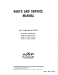
WIN D SH I E L D TR IM
MOUN T I N G
ST R I P. RH
• Secure the ski assembly to the lower end of the
spindle tube assembly by inserting the s crew (3) and
bushing through the s ki damper, spring mounting
bracket and spindle tube as illustrated. Apply 30
foot-pounds torque to the locknut (2). Do not overtighten locknut as ski assembly should float fr eely
on the spindle.
M OUNTING
STRIP. LH
7/8-I N CH LONG
ONLY)
•
NOTE: Be certain to install skiis with pivot of ski
damper forward and adjus ting nut to outs ide of Ski Daddler as illustrated.
• Repeat procedure for oppos ite ski.
NOTE : Properly installed skiis s hould toe out 0- to
1/2-inch at the front end and s hould be symmet rical
about the centerline of the s l ed. If ne cessa ry, refer
to paragraph Steering and Ski Ass e mbly Alignm ent
procedures.
TOE O U T 0 - TO 1 /Z-IN CH MAX I MUM
Ski Damper Adjustment
To adjust the ski damper assemblies, remove the
cotter pin (figure 1) and tight en or loosen the adjus ting nut as required to achieve t he desired
tension. Replace cotter pin and repeat p rocedure
on oppos ite ski assembly.
15-I NCH T RAC K SLED SHOWN
Figure 2
• Using the original screws, loosely secure the
mounting strips and windshield to the hood as s embly
s tarting at the center and working to the sides . Be
certain to position the 7/8- inch l ength screw in the
end position shown in figure 2.
Install Windshield Assembly
• Disconnect hood har nes s at the quick disconnect.
• Engage the ends of the mounting strips over the
t rim s t rip on the windshield and then tighten the
screws, starting at the sides and working to the
center. Remove the protective_~overing from the
mounting strips. NOTE: Check mounting s trips
for sharp edges or corners. Use a fine - tooth file
to smooth any s harp edges and corners.
• Remove hood assembly. Refer to Hood Removal
and· Installation procedure.
• Back off the locknut (figure 2) and r emove the
7/8- inch length screw us ed to secure the hood
harness clip and the end of the ri ght- hand mounting
strip to the hood. NOTE: The hood harness clip,
locknut and 7/8 - inch l ength screw (figure 2) are
us ed on the 15- inch track s l eds only.
• Attach the hood harness clip to the 7/8- inch
length screw and secure with locknut.
• Replace the hood assembly.
• Remove the remaining s crews s e curing the
right- and left-hand mounting s trips to the hood.
Remove the mounting strips.
Fuel Mixture Inst ructions
,r--W
- -AR-N-IN
-G-"I
• Remove the protective plas tic cover from the
windshield. Place the windshield in pos ition on the
hood assembly. Replace the mounting str ips as
shown in figure 2.
Never fill the gaSOline tank while the
engine is hot.
Wipe off any spilled
gasoline before attempting to start
engine.
2
1002473
PREDELIVERY INSTRUCTIONS
The correct oil-to-gas oline ratio is 20: 1 (20 parts
r egular gasoline to 1 part oil). Too much oil will
cause carbon deposits. Too little oil or a poor mix
will cause insufficient lubri cation and possible
engine damage.
USia
Lubrication
A low-temperature grease must be applied to the
zerk fittings located on the steering spindle tubes;
after apprOximately each 20 hours of use. The chain
case housing must be checked after each 10 hours of
use and No. 2 lithium bearing grease added as
required.
IM PORT ANT: Gasoline and oil s hould be mixed at
temperatures above zer o. At temperatures below
ze ro gas and oil mix with diffi culty.
The bearing cup retainers that hold the drive and
idler sprocket seal bearings should be repacked with
No. 2 lithium bearing grease whenever the bearings
are removed during normal maintenance. No.2
lithium bearing gr ease may also be applied to the
inside of the drive and idler sprocket bearing retaine r s dur ing nor mal maint enance.
Fuels containing additives are not r ecommended for
use in Ski-Daddler engines. For mixing with gasoline, use Citgo, Rislone or Kendall oil prepar ed
exclusively for use in air-cooled, 2-cycle engines.
IMPORTANT: Some outboard motor oils contain an
additive that works well in outboar d motors that
ope rate at much lower tempe ratures because they
are water cooled. However, the additives may cause
spark plug fouling in the air-cooled engines used on
Ski - Daddler snowmobiles.
Grease may also be applied as required to the wearplates and U-strap securing the steering column to
the roll bar.
SERVICE AND REPAIR
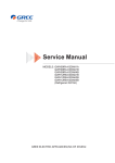
Use a mixture of gasoline and oil as shown in the
Fuel Mixture Chart. Never use gasoline left over
from the summer or previous winter.
c
Hood Removal and Installation
• To remove the hood and headlight assembly,
disconnect the hood and the sled wiring harness at
the quick-disconnect below the console on the rightRelease the hood latch
hand side of the sled.
assemblies and then remove the hood and headlight
assembly by lifting back section first.
FUEL MIXTURE CHA RT
OIL (Ounces )
o
4
8
12
16
20
24
5
4
/
3
/
2
o
V
~ ./
/ .,
/
~
V
V
28
32
v
/
36
40
• To install the hood and headlight assembly,
place the hood in position on the sled so that the
forward hood clip and the bottom edge of the hood
engages the clips along the inside edge of the
bumper.
/"
./
-"
./
/"
./
• Engage the left- and right-hand latch assemblies and insert safety pins to secure the hood· to
the main frame .
./
"
• Connect the wiring harness using the connector
plug located below the console on the right-hand side
of the sled.
u. s. Ga ll on,
I m pe ,;~ 1 Ga lion,
T-
GA SOLINE
(Gallons)
--
GASOLINE/OIL RATlO- 20 t o 1
Hood Assembly Repair
Mix the gasoline and oil thoroughly i n a clean container kept for this purpose only. The best way to
ens ure a good mix is to pour the oil into a container
with about one gallon of gas oline and mix thoroughly.
Then add additional amounts of gas oline as s hown on
the Fuel Mixture Chart. Fill Ski-Daddler gas t ank
from this separate container of mixed fuel. Use a
funnel with a fine-screen s traine r when filling the
tank.
1002473
AMF Fiberglass Repair Kits are available through
your authorized AMF Distributor.
For large
repairs, order AMF Fiberglass Repair Kit No.
1510693. Smaller repairs can be made with Repair
Kit No. 1510765. Paint all repaired areas on the
hood using AMF -Orange color paint available in
easy-to-use spray container, AMF Part No.
1510828. Follow the instructions in the kit when
making repai rs.
3
...
SERVICE AND REPAIR
Replace Lamp Assemblies
(15 -Inch Sleds Only)
Headlight. Tb replace the headlight bulb, raise the
headlight assembly; remove the screws securing the
cover assembly and remove the cover assembly.
Remove the defecti ve bulb and replace with new bulb.
See illustrated parts list for correct replacement
part numbers.
Taillight. Remove taillight lens to expose the taillight bulb. Remove the defective bulb and replace
with a new bulb. See illustrated parts list for correct replacement part numbers.
Steering and Ski Assembly Alignment
Good steering ability requires that the skis be
properly set and aligned with the sled body when
the steering handle is placed in the straight-ahead
position. Remove any play in the skis by pulling
the skis toward the center of sled before taking
measurements.
To determine that the skis are
properly aligned, measure the distance between the
inside edges of the skis at the front end and at the
rear. Properly aligned skis should toe out 0- to
1/2-inch maximum at the front. Therefore, the
overall measurement at the front end of the skis
should be no more than 1/2-inch greater than at the
rear. If the skis or steering mechanism are not
properly set, adjust as follows:
Figure 3
• Secure rod end bearing (3) to spindle arm (6) as
illustrated. Check for proper alignment and then
tighten jam nuts (4) to secure both rod end bearings.
NOTE: If a greater adjustment is required than that
permitted by the steering linkage assembly, it will
be necessary to align the ski by making the adjustment at the spindle tube assembly as follows:
• Remove screw (5, figure 4) and locknut (6) securing spindle tube assembly (7) to spindle arm (8).
• Place steering handle in a straight-ahead
position.
Refer to Hood
• Remove spindle arm (8) and rotate ski and
spindle tube one notch in the required direction;
replace and secure spindle arm to the spindle tube.
Apply 20 foot-pounds torque to the locknut (6).
• Remove the bolt (1, figure 3), two spacers (2),
bottom spacer and locknut securing the rod end
bearing (3) to the spindle arm (6).
• Recheck the skis for proper toe out and alignment as previously described.
• Remove the hood assembly.
Removal and Installation.
NOTE: Ski-damper adjustment is not normally required during Ski-alignment procedures. However,
if adjustment is desired, tighten or loosen the adjusting nut shown in figure 1 as required to obtain
the desired tension.
• Loosen the jam nuts (4) securing both rod end
bearings (3) to the tie rod (5).
NOTE: If both skis need adjustment, repeat procedure for the opposite ski.
• Move the affected ski into proper alignment and
recheck measuring points to insure that the skis toe
out 0- to 1/2-inch maximum at the front end and are
in the same orientation with the sled body as shown
in figure 2.
Steering Damper Adjustment
The steering damper assembly (figure 3) is set at
the factory and should require no further adjustments.
• With skis properly set and steering handle in the
straight-ahead position, rotate tie rod (5, figure 3)
as required to bring rod end bearing (3) in line with
the spindle arm (6).
To Remove Drive Chain
• Remove the hood assembly.
Removal and Installation.
4
Refer to Hood
1002473
~I SERVICE AND REPAIR leSla~
c
!
CAUTION
• Loosen the locknut (8, figure 3) and serrated
washer (7).
During reassembly, apply 10 footpounds torque to the locknut (8).
l
Always disconnect spark plug wires
before working on the engine or drive
elements.
• Push the driven clutch toward the drive clutch
to permit removal of the variable-speed drive belt
from the drive clutch. If necessary the drive belt
can be removed from the drive clutch after the
driven clutch is removed from the bearing clamps .
• Remove the locknut securing the chain cover top
and remove chain cover top and spacer sleeve.
• Loosen the bolts (1, figure 4) on both cam up rights (2) and rotate the cam and shaft (3) as required to loosen the chain tension. During reassembly, apply 30 foot-pounds torque to the bolt (1).
• Remove the locknuts (7, figure 6) securing the
bearing clamps (8) and remove the bearing clamps.
During reassembly, apply 5 foot-pounds torque to
the locknuts (7).
• Remove the cotter pin, slotted nut and washer
securing the top sprocket to the driven clutch shaft.
Remove the top sprocket and chain together.
• Lift the driven clutch and drive belt clear of
the brake assembly and remove the variable-speed
drive belt.
• Reassembly is the reverse of removal. Perform drive chain adjustment procedures and add
No. 2 lithium bearing grease as required to the
chain case.
• Install replacement drive belt. Use AMF Part
No. 37880 on Models SD15M26A and SD15M28AAMF Part No. 37492 on Models SD15M22B and
SDI5M23B; AMF Part No. 34635 on Models SDI8M29A and SD18M30B.
Drive Chain Adjustment
c
NOTE: Variable-speed drive belt installation procedures are the reverse of removal except that the
belt must first be placed around the driven clutch
and then around the drive clutch. Afterins tallation,
perform the drive chain adjustment, variable-speed
belt adjustment and the drive clutch alignment
procedures.
A properly adjusted drive chain (figure 4) should
have a 1/8- to 1/4-inch slack. Check and adjust
chain as follows:
• Remove the locknut securing the chain cover
top and remove chain cover top and spacer sleeve.
• Rotate the upper sprocket to tension one side of
the chain and then check the opposite side for proper
slack. If adjustment is required, loosen the bolts
(1) securing the cam uprights (2) on each side.
During reassembly, apply 30 foot- pounds torque to
the bolts (1).
• Rotate the cam (3) counterclockwise to tighten
or until the chain is properly tensioned. Hold the
cam in this position while tightening the cam upright
bolts (1) on each side. Be certain the lateral alignment between the drive clutch and the driven clutch
(4) is maintained while the cam upright bolts are
tightened.
• Recheck chain tension before replacing the
chain cover, top and spacer sleeve.
To Remove Variable-Speed_ Drive Belt
-
• Remove the drive chain.
To Remove Drive Chain.
Refer to paragraph
Figure 4
• Remove the clutch guard assembly.
I002·17l
5
SERVICE AND REPAIR
Variable-Speed Drive Belt Adiustm~nt
• Reassembly is the reverse of removal. Perform variable-speed dri ve belt adjustment and drive
clutch alignment procedures.
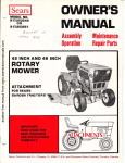
Proper tension for a new drive belt should be obtained when the clutch centers are set to the B
dimension shown in figure 5 for the applicable model
snowmobile.
)
Drive Clutch Alignment
• Remove the hood assembly.
RemOVal and Installation.
IMPORTANT: Do not use antislip belt dressing.
Belt slippage is a safety feature which prevents
overstressing drive-system components .
• To adjust drive belt tension, loosen the locknut
(8, figure 3) securing the clutch rod tensioner to
the main frame assembly.
Refer to Hood
Always disconnect spark plug wires
before working on the engine or drive
elements.
NOTE: If the drive belt is wearing unevenly, check
alignment as described in Drive Clutch Alignment
procedures.
• Remove the clutch guard.
• Loosen the engine holddown nuts (figure 5) securing the engine supports to engine mount straps .
• Move the driven clutch (9) in the direction required to obtain proper belt tension. Hold this position while tightening the locknut to secure the clutch
rod tensioner. Be certain the washer (7) and bar
serrations are properly engaged. Apply 10 footpounds torque to the locknut (8).
• Place a straightedge on the fixed face of the
drive clutch and move the engine until the offset
between the straightedge and the front and rear
edges of the driven clutch is set to the A dimension
as shown in figure 5. Rotate driven clutch 90degrees and repeat procedure.
To Remove Drive Clutch
• Remove the hood assembly.
Removal and Installation.
!
CAUTION
• Tighten engine holddown nuts and recheck
alignment.
Apply 25 foot- pounds torque when
tightening the engine holddown nuts.
Refer to Hood
!
A
Always disconnect spark plug wires
before working on the engine or drive
elements.
• Remove the clutch guard assembly.
• Loosen the locknut (8, figure 3) and serrated
washer (7) securing the clutch rod tensioner to the
main frame. During reassembly, apply 10 footpounds torque to the locknut (8).
B
c
(TORQUE)
FT- LB
MODEL NO.
ENGINE
CLUTCH
0.24
12·1/2
55 ±.5
SD15M28A
292
0.24
12-1/2
55.± 5
SD15M26A
340
780M
780M
0.26
12·1/2
70 .± 5
SD15M22B
399
9· R
0.26
12·1/2
70 .± 5
SD15M23B
439
9·R
0.26
12·1/2
70 .± 5
SD18M29A
650
11·R
0.26
12·1/2
70 .± 5
SD18M30B
793
11·R
• Push the driven clutch toward the drive clutch
to permit removal of the variable-speed drive belt
from the drive clutch. If necessary remove belt
after drive clutch is removed from engine.
• To remove the drive clutch, remove the clutch
adapter bolt and washer. If necessary, use a clutch
puller and remove the drive clutch. NOTE: During
reassembly on Models SD15M28A and SD15M26A
only, apply 50 to 60 foot-pounds torque to the clutch
bolt. All other models require 70 ± 5 foot-pounds
torque.
HOLDDOWN
NUTS
VIEW
)
0
Figure 5
6
1002473
•
~I SERVICE AND REPAIR
If4 Si aij
the castle nut (4) as required to permit the brake
pads (5) to just clear the brake disk. Reinstall the
cotter pin. To adjust for excessive play in brake
cable or lever position, loosen jam nuts (6) and
move brake housing (3) as required. Tighten jam
nuts.
To Remove Driven Clutch
NOTE: The procedures required to remove the
driven clutch are the same as those desc ribed in
paragraph To Remove Variable-Speed Drive Belt.
To Remove Brake Assembly
To Remove Carburetor
• Remove hood assembly. Refer to Hood Removal
and Installation.
• Remove the locknut securing the throttle rod
screw to the carburetor linkage. Remove the throttle
rod screw and jam nuts.
! CAUTION l
Always disconnect the sparkplugwires
before working on the engine or drive
elements.
• Remove the screws securing the ram tube to the
carburetor and remove the ram tube.
• Disconnect the fuel lines at the carburetor.
Wipe up any spilled gasoline immediately. Be certain to note the position of the gas line and impulse
lines to insure proper reassembly.
• Disconnect brake cable and housing (3, figure 6)
at brake mounting bracket and at brake actuating
lever.
• Remove the jam nuts and lockwashers securing
the carburetor to the intake manifold and remove the
carburetor.
• Remove the bolts and lockwashers securing the
mounting bracket to the driven clutch mounting.
• Remove the brake assembly.
c
• Remove the gasket. Do not damage the gasket
if required for reassembly. NOTE: Replacement
carburetors are supplied with a new gasket.
• Installation procedures are the reverse of removal.
Refer to Brake Adjustm ent procedures.
• Installation is the reverse of removal. Adjust
the carburetor as described in the Carburetor
Adjustment procedures.
Brake Adjustment
• To adjust the brake pads (5, figure 6) to the disk
(1), remove the cotter pin (2) and tighten or loosen
Carburetor Adjustments
The carburetors used on Models SD15M22B and
SD15M23B are float type carburetors that utilize
external pumps. The high- and low- speed adjustment screws for these carburetors are located on
top of the carburetor and are easily identified by
the letters HI and LO. The adjustment screws for
all other type carburetors are located on the sides
as shown in figure 7.
When adjusting the carburetor, best results will be
obtained if the adjustments are made on a warm
engine. During carburetor adjustments, DO NOT
FORCE ADJUSTMENT SCREWS INTO SEATS .
• TO ADJUST CARBURETOR - Close the highspeed jet (DO NOT FORCE). Then open the highspeed jet (figure 7) to the settings shown on the
carburetor settings chart for the particular engine
(see figure 8).
Figure 6
I 'If).! 17 i
7
•
~t&:4Mlal SERVICE AND REPAIR I~
!~~CAUTION
The engine can be seriously damaged if
operated with a lean gas mixture (highspeed jet turned in too far) .
• Turn the low speed jet (idle-mixture screw)
shown in figure 7 all the way in (DO NOT FORCE),
then open as shown in figure 8 for the particular
engine. This adjustment controls the mixture at
idling speeds. A lean idle mixture will result in
poor acceleration.
Figure 7
Keep the idle speed slower than the clutch engaging
speed by adjusting the idle-speed screw. NOTE: Do
not use the low-speed jet to adjust for idle speed.
NOTE: Figure 7 shows a throttle-wire. If
throttle plate fails to open completely when
throttle control lever is depressed, loosen
throttle-wire adjustment screw and readjust
wire as required to open the throttle.
To Remove Fuel PumpModels SD1SM22a and SD1SM23B only
the
the
the
the
!~ ~~~TION
!
Always disconnect the sparkplugwires
before working on the engine or drive
elements.
CARBURETOR SETTINGS CHART
MODEL NO.
SERIES
CLASSIFICATION
ENGINE
HIGH -SPEED JET
LOW-SPEED JET
SD15M28A
XX-1300
292
+ 1/8 0
1 _ 0
pen
+ 1/8
1-1/8 _ 0 Open
SD15M26A
XX-1340
340
+ 1/8
1 _ 0 Open
+ 1/8
1-1/8 _ 0 Open
SD15M22B
XX-1400
399
+ 1/8 0
1 _ 0
pen
1-1/2 + 1/8 Open
- 0
SD15M23B
XX -1440
439
+ 1/8 0
1 _ 0
pen
+ 1/8
1-1/2 _ 0 Open
SD18M29A
XX-1650
650
+ 1/8
7/8 _ 0 Open
+ 1/8
1-1/8 _ 0 Open
SD18M30B
XX-1800
793
7 /8
~ ~/8
Open
+ 1/8
1-1/8 _ 0 Open
-
The above carburetor settings are for factory stock engines. Modified engines, exhaust systems,
carburetion and various altitudes may require different settings for satisfactory operation.
Figure 8
8
10024 73
D
ERVICE AND REPAIR
• Disconnect the gasoline lines at the fuel pump.
Note the pOSition of the lines to insure proper reassembly. Disconnect the impulse line. Wipe up any
spilled gasoline immediately.
• Remove the heat shield attached to the roll bar
and main frame between the engine and the muffler.
• Disconnect the engine wiring harness and
loosen or remove all wiring holddown clips. Disconnect the ground lead.
• Remove the locknut and washer securing the
fuel pump to the mainframe. Remove the fuel pump
and mounting bracket as a unit.
• Remove the locknuts, washers, rubber spacers
and bushings securing the engine and engine
mounting straps to the main fram e. NOTE: The
carriage bolts are held in position with Tinnerman
nuts and need not be removed. Do not remove the
shockmounts unless it is necessary to replace them.
During reassembly, tighten the locknuts sufficiently
to allow a 5/16-inch clearance between bottom of
the shock mount and top surface of the main frame.
• Reassembly is the reverse of removal.
To Remove Engine - Models SD15M28A,
SD15M26A, SD15M22B and SD15M23B only
• Remove the hood assembly.
Removal and Installation.
Refer to Rood
IMPORT ANT: Be certain all wiring and gasoline
lines are clear before attempting to remove the
engine.
!~~CAUTIO~
Always disconnect the sparkplugwires
before working on the engine or drive
elements.
c
• Lift the engine and engine mounting straps until
the straps are clear of the carriage bolts and remove the engine and straps as a unit.
• Remove the drive clutch. Refer to paragraph
To Remove Drive Clutch.
• Release the exhaust manifold at the engine on
Models SD15M28A and SD15M26A only. Refer to
paragraph To Remove Muffler.
NOTE: The Illustrated Parts List section of this
manual contains detailed exploded views of the
engine and support assemblies which will be helpful
if referred to during engine removal procedures.
For engine maintenance instruction, refer to the
engine manual supplied with each sled.
• Remove the bolt and washers securing the
engine to the engine mounting plate and remove the
engine. During reassembly, apply loc- tite to the
bolt threads and tighten bolts to 18 foot-pounds
torque.
• Remove the caps crews and washers securing
the carburetor heat shield to the intake manifold
and remove the heat shield.
• Installation is the reverse of removal.
To Remove Engine Models SD18M29A and SD18M30B only
• Disconnect the gas lines at the carburetors.
Disconnect impulse lines at the engine. Wipe up any
spilled gasoline immediately. Note the position of
all lines to insure proper reassembly.
• Remove the hood assembly.
Removal and Installation.
I
• Remove the capscrews and spring lockwashers
securing the left- and right-hand intake manifold to
the engine. Remove the intake manifolds, carburetors and ram tubes as a unit.
-
Refer to Hood
CA~TION
Always disconnect the sparkplugwires
before working on the engine or drive
elements.
• Remove the engine-to-manifold gasket if required for reassembly. NOTE: New, replacement
engines are supplied with new engine-to-manifold
gaskets.
• Remove the drive clutch. Refer to paragraph
To Remove Drive Clutch.
NOTE: The Illustrated Parts List section of this
manual contains detailed exploded views of the
engine and support assemblies which will be helpful
if referred to during engine removal procedures.
• Remove the exhaust system on Models SDI5M22B and SD15M23B only. Refer to paragraph To
Remove Muffler.
100 2473
USia
9
~t.!2131 SERVICE AND REPAIR I~
For engine maintenance instructions, refer to the
engine manual supplied with each sled.
1
CAUTION
!
Always disconnect spark plug wires
before working on the engine or drive
elements.
• Disconnect the gas lines at the carburetors.
Disconnect impulse lines at the engine. Wipe up any
spilled gasoline immediately. Note the position of
all lines to insure proper reassembly.
• Check gas cap and indicator assembly to be
certain tank is empty, or nearly empty.
• Disconnect the throttle cable at the carburetor
linkage and remove the metric nuts and lockwashers
securing the carburetors and carburetor linkage to
the engine. Remove the carburetors and linkage as
a unit. On Model SD18M29A, remove the carburetor,
linkage and intake manifold as a unit.
• Remove the gas cap and indicator assembly (1,
figure 9).
• Remove the bolts (3) and washers securing the
gas spill chute (2) to the main frame and remove the
gas spill chute.
• Disconnect the tank- to-carburetor gas lines (6)
at the gas tankoutletfitting (5). Wipe up any spilled
gasoline immediately.
• Remove the gas tank (4) by carefully sliding the
tank up and away from main frame. IMPORT ANT:
Do not damage the gas tank outlet (5) when removing
the tank.
• Remove the carburetor heat shield.
• Remove the engine-to-manifold gasket if required for reassembly. NOTE: New, replacement
engines are supplied with new engine-to-manifold
gaskets for Model SD18M29A. On Model SD18M30A,
new gaskets are supplied with the carburetors only.
• Disconnect the engine wiring harness and
loosen or remove all wiring holddown clips. Disconnect the ground lead.
Do not attempt to make any repairs to
the gas tank, Use extreme care when
removing the gas tank. Do not remove
tank near flame or open fire.
• Remove the clamps securing the exhaust megaphones to the megaphone support weldment. Release
the extension springs at the engine and remove the
megaphones. Note the position of the clamps to
insure proper reassembly.
)
• Gas tank installation procedures are the reverse of removal. NOTE: If the original tank is not
to be installed, it will be necessary to remove the
gas tank outlet (5) and the attached gas line filter;
also the pressure relief valve (8). These items are
to be installed on the replacement tank.
• Remove the bolts and washers securing the
engine mounting straps to the main frame and shock
mounts. Remove the engine and mounting straps
clear of the sled. During reassembly, do not tighten
the engine mount bolts until after completing clutch
alignment. After clutch alignment, tighten engine
mount bolts to 9 foot-pounds torque.
NOTE: If more clearance is desired, remove the
seat assembly. The locknuts and washers securing
the seat to the main frame are accessible through
the seat tote pouch.
• Remove the bolts and washers securing the
engine mount frame to the engine. Remove the
engine. During reassembly, apply loc-tite to the
bolt threads.
• Installation is the reverse of removal.
To Remove Gas Tank
• Remove the hood assembly.
Removal and Installation.
)
Refer to Hood
Figure 9
10
1002473
e
SERVICE AND REPAIR
c
To Remove MufflerModels SD15M28A and SD15M26A only
To Remove Exhaust Megaphones Models SD18M29A and SD18M30B only
• Remove the hood assembly.
Removal and Installation.
NOTE: Model SD18M30B has a three megaphone
system whereas Model SD18M29A utilizes a two
megaphone system.
Refer to Hood
• Remove the hood assembly.
Removal and Installation.
Always disconnect the sparkplugwires
before working on the engine or drive
elements.
I
~~UTIO~:]
Always disconnect the sparkplugwires
before working on the engine or drive
elements.
• Loosen the clamp securing the muffler to the
dual-exhaust manifold.
• Loosen the bolt and nut securing the muffler to
the mounting band assembly. Remove the muffler.
• Remove the clamps securing the megaphones to
the megaphone support weldment. Note the position
of each clamp to insure proper reassembly.
• Installation procedures are the reverse of
removal.
c
Refer to Hood
To Remove MufflerModels SD15M22B and SD15M23B only
• Release the extension springs securing the
megaphones to the engine exhaust manifold and remove the megaphones.
• Remove the hood assembly.
Removal and Installation.
• Installation procedures are the reverse of
removal.
!
Refer to Hood
CAUTI~~
To Remove Sprocket Seals and Bearings
• Sprocket seals and bearings are located on each
end of the drive sprocket assembly drive shaft. To
replace the seals or bearings it will be necessary
to remove the drive sprocket assembly as described
in the follOwing paragraph.
Always disconnect the sparkplugwires
before working on the engine or drive
elements.
• Remove the screws, washers and locknuts securing the muffler band asse-mblies to the muffler
bracket and to the heat shield.
To Remove Drive Sprocket Assembly
• Remove the hood assembly and set the machine
on its right-hand side.
• Remove the screws, washers and locknuts securing the heat shield to heat shield support attached
to the roll bar. Remove the heat shield.
f
• Remove the retaining rings securing the muffler weldment to the exhaust manifolds.
Always disconnect spark plug wires
before working on the engine or drive
elements.
• Remove the muffler weldments. Note the position of both mufflers to insure proper reassembly.
• Remove the suspension assembly. Refer to
paragraph To Remove Suspension Assembly.
• Remove the muffler band assembly from each
muffler.
• Remove the lower sprocket from the drive
sprocket shaft and remove the sprocket and chain
as described in paragraph To Remove Drive Chain.
• Installation procedures are the reverse of
removal.
-1002473
C~UTION
11
•
SERVICE AND REPAIR
• Remove the screws (figure 11) andlockwashers
securing the back end of the suspension assembly to
main frame.
• Pivot the suspension assembly and traction belt
about the front axle to approximately 90 degrees.
• Using a screw driver, carefully pry the oil
seals (figure 10) away from the bearings at each
end of the drive shaft.
• Remove the carriage bolts and nuts securing
the bearing retainers to each side of the main frame.
Remove the retainers. During reassembly apply No.
2 lithium bearing grease to the bearing retainers.
• Remove screws and lockwashers securing the
suspension assembly to the front end of the main
frame and remove the suspension assembly.
• Move the drive shaft and sprocket assembly
toward the chain side until the opposite end of the
shaft clears the other side. Remove the drive
sprocket assembly. NOTE: With the removal ofthe
drive sprocket assembly, the traction belt will also
be free for removal.
• Installation is the revese of removal. During
reassembly, follow the instructions outlined in
paragraphs Traction Belt Tension Adjustment,
Traction Belt Alignment and Suspension System
Adjustment.
To Remove Traction Belt
• To replace the sprockets, remove the ball
bearing, oil seal, collar and idler wheel. Remove
the screws and nuts securing the support plate and
sprocket to the drive shaft and sprocket plate
assembly. Remove the sprocket.
To remove or replace the traction belt itis necessary to first remove the suspension assembly and
then the drive sprocket assembly. Refer to the
applicable paragraphs for removal procedures.
• Reassembly is the reverse of removal. During
reassembly follow instructions outlined in the paragraphs Traction Belt Tension Adjustment, Traction
Belt Alignment and Drive Chain Adjustment.
IMPORTANT: When installing the traction belt,
follow the instructions outlined in paragraphs traction Belt Tension Adjustment, Traction Belt Alignment and also recheck Suspension System Adjustment.
Traction Belt Adjustment
IMPORTANT: The traction belt must be checked
regularly for proper alignment and tension. When
necessary to adjust the belt, first perform the traction belt alignment and then complete the traction
tension adjustment.
Traction Belt Alignment
• Set the snowmobile on a level surface and
raise the back end.
• Stand to the rear of sled and visually check the
space between the slide rail and the edges of the
track. NOTE: On a properly aligned track this
space should be the same. Start the engine and
again visually check to be certain the track remains
centered while the track is running.
Figure 10
To Remove Suspension Assembly
• Remove the hood assembly and set the machine
on its right-hand side.
• If the track is not centered, stop the engine and
on that side where the edge of the track is closest to
the slide rail, rotate the adjusting screw (figure 11)
until track is centered. Pull the track for a few
revolutions and then start the engine and recheck
alignment. Stop the engine and lock the adjustment
screw in this pOSition.
\: CAUTION
Always disconnect spark plug wires
before working on the engine or drive
elements.
12
1002473
•
ERVICE AND REPAIR
c
lOCKNUT~
PROPER TENSION
1- TO 2-INCH PUll
ADJUST ING SCREW
Figure 11
the track to rotate several turns. Then, stop the
engine and repeat the track tension adjus tment procedure to ensure that proper tension is maintained.
• After track alignment is complete, check track
tension as described in the following paragraph.
c
Traction Belt Tension Adjustment
Suspension System Adjustment
• Set the snowmobile on a clean, flat surface and
raise the back end of the sled.
The suspension system may be adjusted for a s oft or
firm ride, or for varying snow conditions. If a
. firmer ride is desired, adjus t the locknuts (figure
11) to tighten the eyebolts located on each side of the
track. Loosen the eyebolts if a softer ride is de Sired. Adjust front or rear sets of eyebolts equally.
• Check traction belt tension by firmly pulling
the track downward at the center of the track. A
properly tensioned track should have a 1- to 2inch clearance between the Hi-Fax runner and the
track cleats at the appro~mate bottom center of the
track. NOTE: Do not attempt this with the engine
running. Traction belt cleats are sharp and must be
handled carefully.
Spark Plug Replacement
To maintain top engine performance the condition
of the spark plugs should be checked periodically
and the gap reset to 0.020- inch us ing feeler gauge.
During reassembly apply 18 to 20 foot pounds
torque.
• If adjustment is necessary, loosen the locknuts
(figure 11) on each side of the sled and rotate the
adjusting screws as required to obtain proper track
tension. IMPORTANT: Adjust both screws equally
so as not to disturb the track alignment. Retighten
the locknuts on both sides of the snowmobile.
Spark plug condi tion may be determined by the colo r.
A carbonized plug is black; a burnt plug is pale gray,
whereas a normal functioning spark plug i s brown.
! CAUTION !
-
Never run the engine inside a building
without first opening all doors and windows to insure proper ventilation.
When replacing spark plugs, use AMF - approved
spark plugs to insure proper spark plug heat ranges
for a particular engine. NOTE: The Spark Plug
Chart is provided to identify spark plugs for light
or severe service.
• Raise the back end of the snowmobile until the
track clears the ground. Start the engine and allow
I 0 0 2-17J
13
•
~t. .5iiMI31 SERVICE AND REPAIR I~
SPARK PLUG CHART
MODEL NUMBER
ENGINE
LIGHT SERVICE
SEVERE SERVICE
SD15M28A (XX-1300)
292
38058 (N60 or *41XL)
38068 (N57 or 41XL)
SD15M26A (XX-1340)
340
38058 (N60 or *41XL)
38068 (N57 or 41XL)
SD15M22B (XX-1400)
399
38068 (N57 or 41XL)
38068 (N57 or 41XL)
SD15M23B (XX-1440)
439
38068 (N57 or 41XL)
38068 (N57 or 41XL)
SD18M29A (XX-1650)
650
1002607 (K7 or SN82F)
1003068 (K57R)
SD18M30B (XX-1800)
793
1002996 (L81 or S40F6)
1003069 (L54R)
*Optional
ENGINE BACKFIRES THROUGH CARBURETORS.
Carburetor fuel-supply channel clogged. Carburetor set too lean.
Wiring Diagrams
Electrical wiring diagrams shown on the following
pages are provided for the trained technicians using
this manual. Each diagram is identified with the
model number of the snowmobile to which it applies.
ENGINE BACKFIRES THROUGH EXHAUST. Incorrect or faulty spark plug(s); faulty ignition coil
or condenser; loose ignition wiring.
ENGINE OVERHEATS. Insufficient or incorrect
grade oil in fuel mixture; carburetor or fuel line
partly clogged; carburetor setting too lean; ignition
timing too slow.
Troubleshooting
ENGINE HARD TO START. Fuel line blocked or
leaking; ruptured fuel-pump diaphram; water in
fuel, flooded or loose impulse line; ignition or
switch wiring loose or grounded; spark plug(s)
fouled or faulty; contact breaker points pitted or
burned; quick-kill switch in off pOSition.
)
BRAKES. Excessive play in handbrake due to loose
brake cable or worn pads.
TRACTION BELT. Poor traction; check traction
belt for alignment and tension; worn sprockets.
ENGINE STOPS. Fuel tank empty; fuel flow obstructed; ignition system faulty.
Spark plug(s)
fouled or dirty. Engine too hot and pistons seizing;
carburetor setting too lean or incorrect grade of oil
being used, impulse line loose.
CLUTCH. Automatic clutch fails to engage at
proper RPM's (see figure 12). Check variablespeed drive belt for proper tension and alignment.
CLUTCH ENGAGEMENT SPEEDS
ENGINE OPERATES IRREGULARLY. Sparkplug(s)
loose, fouled or faulty; ignition switch wiring
shortSd.; carburetor out of adjustment or dirty.
Engine holddown bolts loose; ignition timing off.
ENGINE WORKING FOUR-STROKE. Choke shut;
carburetor settings incorrect; dirt preventing carburetor inlet needles from seating properly.
ENGINE LOSES POWER. Poor compression due to
loose head and crankcase bolts. Faulty ignition;
timing; piston rings sticking due to the use of improper oil. Carbon deposits in cylinder.
CLASS
ENGINE
ENGINE RPM
XX-1300
292
4300 ±.300
XX-1340
340
4300 ±300
XX-1400
399
4400 ± 300
XX-1440
439
4400 ± 300
XX-1650
650
4300 ±300
XX-1800
793
4300 ± 300
Figure 12
14
1002473
J
•
SERVICE AND REPAIR
STEERING. Poor steering ability caused by improperly adjusted skis; steering linkage loose or out
of adjustment. U-bracket bolts on roll bar too tight
or too loose. Spring, U- bracket loose.
EXCESSIVE FUEL CONSUMPTION. Carburetor
fuel line or gas tank leaking; choke closed; incorrect carburetor setting.
SKI ASSEMBLY. Poor steering ability due to loose
skis; worn wear rod. Poor riding characteristics
due to loose or defective ski-dampers.
THROTTLE CONTROL. Excessive play in throttle
control lever caused by loose throttle control cable.
MODEL SD18M29A
ENGINE
HIRTH 650
I
I
c
L
BLACK
TACHOMETER
RED
WHITE
WHITE-RED
GRE~;o
C
BLACK
BLACK
=
GROUND AT ENGINE
STARTER BOLT
IGNITION SWITCH
QUICK KILL
SWITCH
OFF
\
WHITE
WHITE-RED
~-~--+______~__________~______~G~R=E=E~N____~3~lb~~~~~
RED
10024 73
15
31
\
RUN
I
/
I
MODEL SD18M30B
QUI CK KILL
SWI TC H
-
] ~~ J
IGNI T ION SWITC H
OFF
,
BL AC K
t:l ~
.
•
}
I
~
q) ]
((53
:/
__ J
CE
<
TACHOMETER
."
;a.
I
~AR K
WHITE
WHITE - RE D
RED
«
::::
c-:.
ENG I NE
HI RTH 793
I
~ a:
'a _- I
/ - -77'('--7,)');J»"
....0'1
--l
BL ACK
~
."
::Itt
BLACK
PLUGS
I I- -~
A.
I
RED
~ BLACK
BLUE
GR EEN
-=
I BLUE
'cu'
J
I
I
_ _
=
~
~
;;
lGROUND AT
ENGINE
-=
BLACK
BLACK
CAPACI TOR
IGNITION COIL
u
fI
(
n
)
I)
c
c
""'"'"
<.,
MODELS SD15M28A and SD15M26A
--l
~=::"------.
II~
I _.. __ .,
NOT USEDI 0
•
YELLOW
ENGINE
HIRTH-292
h
HIRTH-340:
r=r4"ttl1j:
L51
I
t-=_ ..J
-YELLOW
...
WH ITE
-..J
lWHITE-RED
WHITE-RED
RED
RED
GREE~TACHOMETER
-=~~--------~'~--~'~B~L~A~CK~~
BLACK»
I
WHITEI
I
~
BLUE
~"
BLUE
CI)
'" GROUND AT ENGINE
STARTER BOLT
."
IWHITE - RED
IGNITION SWITCH
OFF
LIGHTS
ON
\
I
I
_
"
START
,
... ,' ») 530
31
TAILLIGHT
BLUE
50
YELLOW
BLACK
BLACK
BLUE
BLUE
BLUE
I(I< I
QUICK
DISCONNECT
BLUE
~
I11III::
HEADLIGHT
.....
~
.:;
."
~
REDUGREEN
[ __ J
QUICK KILL SWITCH
~
:;;
MODELS SD15M22B and SD15M23B
i--
-l
~
."
=tI
~
ENG IN EI
:::
~~I~\------~--~
AMF-439BPI
I
AMF-399BP
C")
."
::..
~
=tI
."
~
;;
YELLOW
.....
WHITE - RED
WHITE
OJ
WHITE-RED
r-_ _ _ _ _
.,
WHITEI
IWHITE-RED
~B~LA~C~K~»
BLUE
"
BLUE
IGNITION SWITCH
OFF
LIGHTS
ON
\
I
I
START
TAILLIGHT
/
53c
BLUE
50
' /
RED
RED
BLACK
i
GREE~TACHOMETER
)~
IBLACK
GROUND AT ENGINE
STARTER BOLT
-=
BLACK
BLACK
BLUE
BLUE
BLUE
BLUE
HEADLIGHT
QUICK
DISCONNECT
) 530
YELLOW
RED
GREEN
[~
u
QUICK KILL SWITCH
u
.
•
PARTS LIST
Where no code letter appears in the code column,
the part is used on all models to which the particular
figure applies.
All model codes will be listed at the bottom of each
parts list page to provide a ready reference.
ILLUSTRATED PARTS LIST
This section of the dealer's manual consists of an
illustrated parts list and a numerical index.
PARTS LIST
NUMERICAL INDEX
The parts-list consists essentially of exploded-view
illustrations keyed to the figure-reference column
by index numbers. The Parts List is arranged in
the following columns:
The numerical index is provided to afford dealers
and distributors with a means of determining to
which models their s tock applies. The index consists of the following three columns:
Figure-and-Index Number. The number preceding
the dash refers to the figure number on which the
item is shown. The number following the dash .is
the index number keyed to the item shown on the
exploded view.
Part-Number Column. The part-number column
tabulates all parts called out in the parts list. The
part numbers are listed in numerical order starting
with the first digit in the number.
Part Number. The part number column identifies
the item by its assigned part number.
Index-Number Column. The index-number column
reflects the figure-and-index number of the part
within the Parts List. The number preceding the
dash refers to the figure number on which the item
is shown. The number following the dash locates
the item within the given figure.
Description. The description column identifies the
part with descriptive nomenclature.
Quantity. This column provides the total number of
items required per assembly.
Quantity Column. The quantity colUmn reflects the
total number of parts required for the particular
figure-and-index-number application. In certain
cases, quantities differ between sled models . This
circumstance is covered by providing the larger
quantity for the particular figure -and-index number.
In referring to the given figure-and-index
number in the parts-list section, the proper quantity
per sled may be determined.
Model Code. This column identifies, by code letter,
the Ski-Daddler models for which the part applies.
The following lists the code-to-model relationship:
Model
Code
Model
Code
SD15M28A
SD15M26A
SD15M22B
A
B
C
SD15M23B
SD18M29A
SD18M30B
D
E
F
Addendum. Numbers added.
-.
lOON?)
19
i2
::.:,
~
....
C;;
.....
"
.0'
r::
C;;
N
19
o
Ci),
::T
('D
~
o
....
...'"'"'"
\:!
u
u
•
o
~I
Figure
& Index
Number
1-
-1
-2
Part Number
1002010
1002011
1002007
1002008
1002006
1002009
37030
37029
1002785
1002441
1002750
-3
-4
-5
-6
-7
-8
c
37080
35000
37081
35001
1002595
446212
9000127
1002265
1002266
1002263
1002264
1002262
1002267
-9
-10
- 11
- 12
- 13
- 14
- 15
-16
-17
- 18
- 19
-
34058
9415426
33808
9000123
181648
120394
9000125
1002600
1002613
1002601
1002614
1002157
1002619
1002683
1002682
A - SD15M28A
B - SD15M26A
1002473
Qty
Description
SKI-DADDLER, Model No. SD15M28A
.•.••
SKI-DADDLER, Model No. SD15M26A
•....
SKI-DADDLER, Model No. SD15M22B
...•.
SKI-DADDLER, Model No. SD15M23B
•..•.
SKI-DADDLER, Model No. SD18M29A
....•
SKI-DADDLER, Model No. SD18M30B
•....
WINDSHIELD, 15-Inch
.•.•.••••••••.•..
WINDSHIELD, 18-Inch
.........•••....•
HOOD AND HEADLIGHT ASSEMBLY,
.•..•
15-Inch (See figure 2)
HOOD AND HEADLIGHT ASSEMBLY,
15-Inch (See figure 2)
HOOD ASSEMBLY
18-Inch (See figure 2)
BUMPER ASSEMBLY, RH (See figure 2) ...••
BUMPER ASSEMBLY, RH (See figure 2) •.•..
BUMPER ASSEMBLY, LH (See figure 2) •.•..
BUMPER ASSEMBLY, LH (See figure 2) .•••.
STABILIZER, steering
...•.••..•.•..•.•
WASHER, Plain
.•.•.•......•.•.•.......•
LOCKNUT, 7/16-20 THD
...•.••.•.....••.
CONSOLE AND STEERING ASSEMBLY ..•..
(See figure 3)
CONSOLE AND STEERING ASSEMBLY •....
(See figure 3)
CONSOLE AND STEERING ASSEMBLY •....
(See figure 3)
CONSOLE AND STEERING ASSEMBLY •....
(See figure 3)
CONSOLE AND STEERING ASSEMBLY •••••
(See figure 3)
CONSOLE AND STEERING ASSEMBLY •••••
(See figure 3)
LOCKNUT, 1/4 -20 THD
SCREW, Truss HD, 1/4-28 by 1-1/2 IN. LG .
.•.••••.•...•..•.....
WASHER, Formed
LOCKNUT, 1/4-28 THD
•••••..••.••..•..
SCREW, HEX HD, 3/8-24 by 2 IN. LG
.••••
WASHER, Plain, 13/32 ill
........
LOCKNUT, 3/8-24 THD
••.••••.•..••••••
SKI AND SPRING ASSEMBLY, RH (See figure 3)
SKI AND SPRING ASSEMBLY, RH (See figure 3)
SKI AND SPRING ASSEMBLY, LH (See figure 3)
SKI AND SPRING ASSEMBLY, LH (See figure 3)
SEAT AND TAIL LAMP ASSEMBLY
..•.•
(See figure 4)
SEAT ASSEMBLY (See figure 4)
..•....•
MUD FLAP, 15-Inch .••••••••••.•.•..•.••
MUD FLAP, 18-Inch
.....••..........•...
0
••••••••••••••••
0
••••
0
C - SD15M22B
D - SD15M23B
21
le2ia~
PARTS LIST
1
1
1
1
1
Model Code
A
B
C
D
E
1
F
1
1
ABCD
EF
ABC
1
D
1
EF
1
ABCD
EF
ABCD
EF
1
1
1
1
1
2
2
·1
A
1
B
1
C
1
D
1
E
1
F
1
4
4
4
2
4
2
1
1
1
1
1
1
1
1
ABCD
EF
ABCD
EF
ABCD
EF
ABCD
EF
E - SD18M29A
F - SD18M30B
PARTS LIST
•
I~
Figure 1. (Sheet 2 of 2)
MODELS SD18M29A
AND SD18M30B ONLY
30
(REF)
L-__________~,~----------
L-________________
~.
"l-------
L-___________-,.~~-------
22
1002473
o
~I
Figure
& Index
Number
1-20
-21
-22
- 23
-24
-25
-26
-27
-28
-29
-30
Part Number
436752
1002686
1002685
9000122
1002527
1002535
1002471
181577
181566
147579
9000123
37593
1002432
1002433
1002540
1002541
1002429
c
1002430
-31
-32
- 33
- 34
- 35
- 36
- 37
-38
- 39
- 40
-41
-42
- 43
-44
-45
33768
1002784
1002783
9000324
180022
180124
120380
120382
446548
9416904
32532
32528
33769
37595
9000125
225842
181561
120217
120380
1002688
1003019
37345
9000302
120392
9000123
A - SD15M28A
B - SD15M26A
100 2473
Description
Qty
SCREW, PAN HD, 10-32 by 3/4 IN. LG ..•..
STRAP, 15-Inch
....•..•......•....•.....
STRAP, 18-Inch •.•...•.••....•...•......
LOCKNUT, 10 - 32 THD
.•...............
CLUTCH GUARD AND DECAL ASSEMBLY .. .
CLUTCH GUARD AND DECAL ASSEMBLY .. .
STRAP, Clutch guard
.•..••.....•.....
BOLT, HEX HD, 1/4-28 by 1 - 3/4 IN. LG ...
BOLT, HEX HD, 1/4-28 by 3/4 IN. LG ...•.
WASHER, 1/4 ill
.................... .
LOCKNUT, 1/4-28 THD
.•.••.••••.•••...
DECAL, Safety
•..••
ENGINE AND SUPPORT ASSEMBLY
....•
(See figure 5)
ENGINE AND SUPPORT ASSEMBLY
(See figure 5)
ENGINE AND SUPPORT ASSEMBLY
(See figure 5)
ENGINE AND SUPPORT ASSEMBLY
(See figure 5)
ENGINE AND SUPPORT ASSEMBLY
(See figure 6)
ENGINE AND SUPPORT ASSEMBLY
(See figure 6)
SHOCK MOUNT
•.••.....•.•..•. •••.•. ...
SHOCK MOUNT
.•...••...•..•......•.•.•
SHOCK MOUNT
....•.......•.•..•..•.•..
BOLT, Carriage, 3/8-24 by 2-1/4 IN. LG ••.
BOLT, HEX HD, 1/4 - 20 by 1 IN. LG
••...
BOLT, HEX HD, 3/8-16 by 1-1/4 IN. LG .. .
LOCKWASHER, Spring, 1/4 ill
........ .
LOCKWASHER, 3/8 ill
................ .
WASHER, Plain, 3/8 ill
......... . ...... .
WASHER, Plain, 9/32 ill by 1 IN. OD
•....
NUT
...••......•.•.. . •.. ......•.•....
BUSHING
..••••••.••.....•..••••••....
SP ACER, Rubber
•.•.......•.......•..
WASHER
..•.
LOCKNUT, 3/8-24 THD
.••••••.•.•••....
SCREW, SOC HD, 10-32 by 1/2 IN. LG .•.•.
BOLT, HEX HD, 1/4-28 by 1/2 IN. LG .....
LOCKWASHER, Spring, No. 10
.•...•...
LOCKWASHER, Spring, 1/4 ill
........ .
HEA T SHIE LD
........................ .
HEAT SHIE LD
........................ .
SUPPORT, Heat shield
...... .. ........ .
SCREW, Truss HD, 1/4-2 8 by 5/8 IN. LG
.
WASHER, Plain, 1/ 4 ill
................ .
LOCKNUT, 1/4-28 THD
............ .. .. .
0
0
••••••••••
••••••••••••
C - SD15M22B
D - SD15M23B
23
IW Sia~
PARTS LIST
0
••••
•••
•
•
••••
•
••••••
Model Code
4
1
1
4
1
1
ABCD
EF
ABCD
EF
1
2
1
4
3
1
1
A
1
B
1
C
1
D
1
E
1
F
4
4
4
4
4
4
4
ABCD
4
4
4
4
4
4
4
4
16
16
16
16
1
1
1
2
2
2
E
F
ABCD
E
F
E
F
F
E
ABCD
ABCD
ABCD
ABCD
ABCD
E
F
E
F
AB
CD
ABCD
ABCD
ABCD
ABCD
E - SD18M29A
F - SD18M30B
,
I~
PARTS LIST
Figure
& Index
Number
1 - 46
- 47
- 48
-49
- 50
-51
-52
- 53
-54
- 55
- 56
-57
Part Number
1002490
1002491
37811
2791
9000122
132908
1002585
1002586
1002803
9000828
1002808
1002804
9000827
9000827
1002810
1002805
1002802
1002583
1002584
- 58
-59
-60
-61
181637
131099
1002618
1002617
1002699
1002700
1002697
1002698
1002453
1002696
-62
- 63
- 64
-65
-66
37683
1002579
1002578
1002446
1002577
*1002847
*181675
*272712
Qty
Description
.........................
.........................
· .................................
.....
.............
.............
· ................................
SLED HARNESS
SLED HARNESS
SLED HARNESS
CLIP
................ ...
LOCKNUT, 10 - 32 THD
SCREW, RD HD, 10 - 32 by 1/2 IN. LG
TRACK ASSEMBLY, 15- Inch
TRACK ASSEMBLY, 18 - Inch
GUIDE
RIVET
. .......................... ................................... .
CLEAT
.................................................................
CLEAT
.............. ............................................. .... .
RIVET
RIVET
. . .............................
BELT, Track, 3-Inch
.................................
BELT, Track, 4-Inch
..................................
BELT, Track, 6-Inch
SUSPENSION ASSEMBLY, 15 - Inch .................
(See figure 7)
SUSPENSION ASSEMBLY, 18-Inch
(See figure 7)
.................
BOLT, HEX, 3/8-24 by 1 IN. LG
.................. . .............
LOCKWASHER, 3/8 ID
SPROCKET ASSEMBLY, Drive (See figure 8) .
SPROCKET ASSEMBLY, Drive (See figure 8) .
DRIVEN CLUTCH AND MOUNTING ASSEMBLY
(See figure 8)
DRIVEN CLUTCH AND MOUNTING ASSEMBLY
(See figure 8)
DRIVEN CLUTCH AND MOUNTING ASSEMBLY
(See figure 8)
DRIVEN CLUTCH AND MOUNTING ASSEMBLY
(See figure 8)
DRIVEN CLUTCH AND MOUNTING ASSEMBLY
(See figure 8)
DRIVEN CLUTCH AND MOUNTING ASSEMBLY
(See figure 8)
GAS CAP ASSEMBLY, Tank (See figure 9)
..........
MAIN FRAME ASSEMBLY, 15-Inch
..........
MAIN FRAME ASSEMBLY, 15-Inch
.........
MAIN FRAME ASSEMBLY, 18-Inch
.........
MAIN FRAME ASSEMBLY, 18 - Inch
.............................
SHOCK ABSORBER
CAPSCREW, 7/16 by 2-1/4 IN. LG
LOCKNUT, 7/16 THD
....................
•
••••••••••••••••••••••••
..........................
0
0
0
•••••
........
...................................
.............
0
...
.....
.................
"
1
1
1
1
1
1
1
1
30
60
44
44
380
468
2
2
1
1
Model Code
ABCD
E
F
ABCD
EF
ABCD
EF
ABCD
EF
ABCD
EF
ABCD
1
EF
4
4
1
1
1
ABCD
EF
A
1
B
1
C
1
D
1
E
1
F
1
1
1
1
1
1
2
2
)
AB
CD
E
F
*Available as optional equipment only.
A - SD15M28A
B - SD15M26A
C - SD15M22B
D - SD15M23B
24
E - SD18M29A
F - SD18M30B
{00 2n 3
•
~I
c
Figure
& Index
Number
1 -67
-68
-69
-70
-71
Part Number
1002747
181566
147579
9000123
*1002074
1002075
1002069
1002070
1002073
1002440
- 72
*37926
37224
c
PARTS LIST
Description
Qty
.............
....
.................
.... ... ... ...... .
.... .
· ....
1
2
2
2
1
EF
EF
EF
EF
A
1
B
.....
1
C
.....
1
D
1
E
1
F
.........
1
ABCDF
.........
1
E
DE FLECTOR, Exhaust weld
SCREW, HEX HD, 1/4-28 by 3/ 4 IN. LG
WASHER, Plain, 1/4 ill
LOCKNUT, 1/4- 28 THD
INSTRUCTION MANUAL ASSEMBLY
(Not illustrated)
INSTRUCTION MANUAL ASSEMBLY
(Not illustrated)
INSTRUCTION MANUAL ASSEMBLY
(Not illustrated)
INSTRUCTION MANUAL ASSEMBLY
(Not illustrated)
INSTRUCTION MANUAL ASSEMBLY
(Not illus trated)
INSTRUCTION MANUAL ASSEMBLY
(Not illustrated)
PARTS BAG ASSEMBLY, Engine
(Not illustrated)
PARTS BAG ASSEMBLY, Engine
(Not illustrated)
· ....
· ....
*Item 71, Instruction Manual Assembly contains Ski - Daddler documentation.
*Item 72, Contains metric tools for engine maintenance. Not shown.
A - SD15M28A
B - SD15M26A
C - SD15M22B
D - SD15M23B
-1002473
25
Model Code
Not shown.
E - SD18M29A
F - SD18M30B
•
PARTS LIST
26
1002473
•
~I
c
PARTS LIST
Figure
& Index
Number
2-
Part Number
1002785
1002441
-1
-2
-3
-4
-5
-6
-7
-8
-9
-10
-11
-12
-13
-14
-15
-16
- 17
-18
-19
-20
-21
-22
-23
-24
- 25
-26
-27
-28
-29
-30
-31
-32
-33
-34
-35
-
1002750
34984
34271
37045
37000
1002096
132908
9000122
37006
9000122
37005
34991
445170
37001
1002025
37051
*1002155
124818
33647
34058
37055
437028
35027
35028
273407
35029
35023
35024
1002143
9000884
37009
9000461
35022
37471
37709
37033
37031
37034
37032
125680
125680
187759
9413314
Description
HOOD AND HEADLIGHT ASSEMBLY
(See figure 1)
HOOD AND HEADLIGHT ASSEMBLY
(See figure 1)
HOOD ASSEMBLY (See figure 1)
CLIP, Hood
.................... .. .. .. .
RIVET
... ...... .. ................... .
PLATE, Hood
.... . .. . ...... •. . .• ....•.. .
GAS LID AND HINGE ASSEMBLY
...... .
GAS LID AND HINGE ASSEMBLY
.... .. .
SCREW, RD HD, 10-32 THD by 1/2 IN. LG .. .
LOCKNUT, 10-32 THD
..... ... . .... ... .. .
...................... .
HINGE ASSEMBLY
LOCKNUT, 10 - 32 THD
.•. ................
SPRING, Flat
... . . ......... ......•......
ESCUTCHEON, Gas cover
....•.... ... ...
NUT, Spring, 3/16 IN.
. ..•......• .. .. " '.
GAS LID ASSEMBLY
.•...••............
GAS LID
.... ....... . .....•.............
RUBBER BUMPER, Gas lid
•. . •.•. .... ••. .
HEADLIGHT ASSEMBLY
.••.••....•... .
JAM NUT, HEX HD, 1/4-20 THD
•....•.
SPACER
.......... . .....•.....•........
LOCKNUT, 1/4 -20 THD ......•.. . .........
COVER ASSEMBLY, Headlight
.. •• . •.• . ..
SCREW, PAN HD, 8-32 THD by 1-1/4 IN. LG .
SHAFT, Pivot
. .. ....•...•.•.........•...
SHAFT, Spring .• ... .. •.. ............. . .. .
SCREW, Truss HD, 8-32 THD by 3/ 8 IN. LG
SPRING, Extension
. .•... .. . ........... .•.
BRACKET, RH ........•............. . ... .
BRACKET, LH ...•.•.. .......•....... . ...
HARNESS, Hood
. . .. .......•........ .•.
HEADLIGHT
......•.•.•.•.........••...
HOUSING ASSEMBLY (Consists of items . . .•..
27 and 28)
RIVNUT, 8-32 THD .• •. .......•.•.........
HOUSING
•...•.....••. ....... •.• ........
GROMMET, Air duct
.................. .
Am DUCT, Hood
... .......• • .....•.•...
TRIM STRIP, RH
. • •.• •.. . .• ....•.......
TRIM STRIP, RH
.••...........•......•
TRIM STRIP, LH
............• .... .....
TRIM STRIP, LH
..................... .
SCREW, Truss HD, 1/4- 20 THD by 5/ 8 IN. LG
SCREW, Truss HD, 1/4 - 20 THD by 5/8 IN. LG
SCREW, Truss HD, 1/4-20 THD by 7/8 IN. LG
.......... •. .... . .
LOCKNUT, 1/4-20 THD
0
•
•••••••••••
0
Qty
REF
Model Code
ABC
RE;F
D
REF
EF
1
3
1
1
1
2
2
ABCD
EF
1
2
1
1
1
ABCD
ABCD
ABCD
EF
2
1
ABCD
1
4
4
2
4
1
2
1
1
4
2
1
1
1
1
1
ABCD
ABCD
ABCD
ABCD
ABCD
ABCD
ABCD
ABCD
ABCD
ABCD
ABCD
2
1
1
ABCD
ABCD
1
1
ABCD
ABCD
EF
ABeD
EF
ABCD
EF
ABCD
ABCD
1
1
1
6
7
1
1
*Includes applicable items - 17 through -28.
A - SD15M28A
B - SD15M26A
1002473
C - SD15M22B
D - SD15M23B
27
E - SD18M29A
F - SD18M30B
•
PARTS LIST
Figure
& Index
Number
2-36
-37
-38
-39
-40
-41
- 42
-43
-44
-45
-46
-47
-48
-49
-50
-51
-52
-53
-54
)
Part Number
1002166
37389
9000555
34992
445170
35011
34271
35017
1002752
1002754
1002731
9000824
446152
34989
34271
35005
9000123
34983
37591
37080
35000
37081
35001
1002589
181566
9000191
1002280
1002279
A - SD15M28A
B - SD15M26A
Qty
Description
CABLE TIE
•..... ......• .•.•.•... . •....
CABLE TIE
.• •••. .........•. •.••.•. . ...
JACKNUT, Molly, 1/4-20
. ..••.•. .••..•..
ESCUTCHEON, Side
... . .. .•.......•..•.
NUT, Spring
.•.
STRIKE
•.•............ .... .•.........••
RIVET
•.•••••••.••..........•.•.•.•...
HOOD, 15 - INCH
.•.••.•..............••.
HOOD AND AIR DUCT ASSEMBLY
•.•.•.•.
HOOD, Modified
.•..••••.....••
AIR DUCT
••.••••.•••.........•.•.••••
POP RIVET
..•.•••••.••••..•...•..•.•.•
WASHER
.••••.•••••••.•.•.• ... •.••..••.•
CATCH, Hood
.•••.•.. ...•. •.. .•. •••..
RIVET
.••••.......•.•..•.•...•..••••..
GUIDE, Hood
....•••••.•.•..•• ••••••....•
LOCKNUT, 1/4-28 THD
•••••.•.•.••....
SPACER, Bumper •••••.••...••••••••••.••
COVER, Bumper
.•....••.. ••••••....•.•.
BUMPER ASSEMBLY, RH (See figure 1) ••..
BUMPER ASSEMBLY, RH
.•.•...•.•••••••
BUMPER ASSEMBLY, LH (See figure 1) ••••
BUMPER ASSEMBLY, LH
. •• . ••••••••.•..
STOP, Hood
..•..•.••..•.•.••••••.••••••
SCREW, HEX HD
•.••.•.••••••••••
KLICK PIN
•.•.•.....•....••••••••••••.
DECAL, Racing, LH
DECAL, Racing, RH
0
••••••••••••••••••••••••
0
••••••••
0
C - SD15M22B
D - SD15M23B
28
••••••
1
Model Code
ABCD
5
7
2
6
2
4
1
1
1
1
13
13
2
4
6
6
6
ABCD
EF
EF
EF
EF
EF
1
REF
REF
REF
REF
1
2
2
1
1
ABCD
EF
ABCD
EF
ABCD
DEF
DEF
E - SD18M29A
F - SD18M30B
1002473
~I
C
Figure
& Index
Number
3-
Part Number
1002265
1002266
1002263
1002264
1002262
1002267
-1
-2
-3
-4
-5
-6
-7
C
-8
-9
-10
-11
-12
-13
-14
-15
-16
-17
-18
-19
-20
-21
-22
-23
-24
-25
-26
-27
-28
-29
- 30
*37040
*34976
33320
181651
21777
30251
9000125
37041
34942
181643
21777
9000125
30081
124925
37042
34943
181578
147579
34688
34694
34689
9000123
37231
32185
142443
9000122
32187
9417420
32188
32186
1002779
1002779
37159
37486
A - SD15M28A
B - SD15M26A
Des c r iption
CONSOLES AND STEERING ASSEMBLY ..........
(See figure 1)
CONSOLES AND STEERING ASSEMBLY .... . .. .
(See figure 1)
CONSOLES AND ST EERING ASSEMBLY ..........
(See figure 1)
CONSOLES AND STEERING ASSEMBLY .... .... .
(See figure 1)
CONSOLES AND ST EERING ASSEMBLY ..........
(See figure 1)
CONSOLES AND STE ER ING ASSEMBLY ..........
(See figure 1)
STEERING LINKAGE ASSEMBLY
...... . ...... ....
STEERING LINKAG E ASSE MBLY
..................
ARM, Spi ndle
...... .... . .... ...... .... . . . ........ . ........
BOLT, HEX HD, 3/8 -24 T HD by 2-3/ 4 IN. LG
SPACER
...... ...... .... ...... . ........ . ...... . ................
SPACER
.... .... .... . .... .... ...... . . ............ .... ...... . .
NUT, 3/8 -24 THD
........ . .............. . .............. .
TIE ROD ASSEMBLY
TIE ROD ASSEMBLY .. ............ . ...... .. ..................
BOLT, HEX HD, 3/ 8-24 THD by 1-1 / 2 IN. LG
SPACER
.......... . .... . ...... . ................................
.......................... . ..............
NUT, 3/8-24 T HD
.......... . ............ . .................. . ............
ROD E ND
. . .................... .
J A M NUT, HEX, 3/8 -24 THD
TIE ROD
.............. . ...... .... ...................... . .... . .
TIE ROD
. . . . ..................................................
BOLT, HEX HD, 1/ 4-28 THD b y 1-7/ 8 IN. LG
. . ......................
WASHER, Plain , 1/ 4 IN. ID
U -STRAP
. ........................................................
WEARP LATE
.... . ........ . .... . ............................
WEARP LATE
........ .. ........................................
LOCKNUT, 1/4-28 THD
..................................
GRIP, Ha nd
................ . ........................................
THUMB C ONTROL ASSEMBLY, Throttle " " " ..
SCR EW, RD HD , 10 -32 THD by 1-3/ 8 IN. LG.
LOCKNUT , 10 -32 THD
.........................
LEVER, T hum b
.............................
SCR EW, Truss HD, 6-32 THD by 3/ 8 IN. LG.
SPACER
. .... . ............................
CLAMP, Thum b c ontrol
...................
KILL- SWITCH ASSEMBLY
...................
KIL L-SWITCH ASSEMBLY
BRAKE CONTROL ASSEMBLY
... . .........
HAND C ONTROL ASSEMBLY
..................
..
.. ..
..
........
0
•
C - SD15M22B
D - SD15M23B
* 3-1 includes applicable item s -2 thr ough -13.
IOUN7}
PARTS LIS T
29
........................
0
............
Qty
Mod el Code
REF
A
REF
B
REF
C
RE F
D
REF
E
R EF
F
2
2
2
2
4
2
2
2
2
2
4
2
4
4
2
2
2
4
1
1
1
2
2
1
1
1
1
2
2
1
1
2
1
1
ABCD
EF
ABCD
EF
ABCD
EF
I
I
ABCDE
F
E - SD18M29A
F - SD18M30B
-~~~~N~R~nC:~Ln:T=~~~I~
ij ~~
F-
.
3 . (Sh,,, 1 of
Figure
41
40
;;
21
__________====l
•
)
48
I~
25
/ "( "
24
yJiv'l
~ ~23
V
)
J
30
1002473
•
PARTS LIST
c
Figure
& Index
Number
3 - 31
Part Number
1002620
1002427
1002622
-32
- 33
- 34
- 35
- 36
- 37
-38
- 39
c
-40
-41
- 42
- 43
-44
- 45
- 46
-47
- 48
-49
- 50
-51
-52
- 53
-5.4
-55
-56
1002628
*1002638
*1002582
*1002581
*1002271
*1002272
*1002269
*1002270
*1002268
*1002273
9415426
147579
33808
9000123
37374
37036
34271
37135
37072
1002215
1002216
1002213
1002214
1002212
1002217
34735
1002219
35044
37792
37037
120612
9000122
37039
37038
137258
37124
34945
30149
33753
33756
A - SD15M28A
B - SD15M26A
-
Description
THROTTLE CABLE, HOUSING
AND BOOT ASSEMBLY
THROTTLE CABLE, HOUSING
AND BOOT ASSEMBLY
THROTTLE CABLE, HOUSING
AND FITTING ASSEMBLY
STEERING HANDLE AND COLUMN ASSEMBLY
STEERING COLUMN ASSEMBLY
•.•••.•..
STEERING COLUMN ASSEMBLY
.•..•..•.
STEERING COLUMN ASSEMBLY
.•.•••...
MINI-CONSOLE ASSEMBLY
••••..•.•.•.•
MINI-CONSOLE ASSEMBLY
...•..•....••
MINI-CONSOLE ASSEMBLY
.•..•.•....•.
MINI- CONSOLE ASSEMBLY
. .....•.....•
MINI- CONSOLE ASSEMBLY
............ .
MINI-CONSOLE ASSEMBLY
.••......•...
SCREW, 1/4- 28 THD by 1 - 1/2 IN. LG
•...•
WASHER, Plain
.....••.•......•.•..•.•.•
WASHER, Formed
•••••••••..••••.••••.
LOCKNUT, 1/4-28 THD
..•.•.•.•.•••.•..
BAR, Console support
.....•......•.•••
BAR, Console support
...•.•.••.....•.•
RIVET
.•••..•.....•.•••.•.•..•...•.....
PLATE, Console back- up ..•.•...•........
SWITCH, Key (with keys)
•.•••.•......•...
DECAL, LH .•...•..........•.•.•...•....
DECAL, LH ..•••.•.•.•...•.•••.•••.••.•.
DECAL, LH ....••....•••••.•.••••..•....
DECAL, LH .••.....•..•.•.•••.••...••.•.
DECAL, LH .•.......•....•••• • .••••••...
DECAL, LH .•.•..•••.••...•...•.•..•.•..
TACHOMETER
...•........•...•.•.•.••.
DECAL, RH •.•..•.••••.••..•.....•••....
MINI- CONSOLE
.....•.••.••...•.•..... . .
...•..•..•......•.••.•...
MINI- CONSOLE
BRACKET, Console
.....•...•••.........
SCREW, Flat HD, 10-32 THD by 5/8 IN. LG •
.•.•.•.•.••••....
LOCKNUT, 10-32 THD
ROLL BAR, 15-inch
•••••.•••••.•.•......
ROLL BAR, 18-inch
•.••.••••..•.•.•....•
COTTER PIN, 3/16 IN. DIA by 1 - 3/4 IN. LG .
...........•.
WASHER, Steering column
BUSHING, Steering column support
.•..•
SPRING, Spindle .....•.•.•...•..•.•.•.••.
BUSHING, Plain
.•.•.•..•...•••..••••••..
BUSHING, Flange
•••.•••.•••.•.•.•.•.•
C - SD15M22B
D - SD15M23B
* 3 - 33 includes applicable items - 20 through -32.
3-34 includes applicable items - 39 through -46.
*
1002473
31
Qty
Model Code
1
AB
1
CDE
1
F
1
1
1
1
1
1
1
1
1
1
2
2
2
2
2
2
AB
CDE
F
A
B
C
D
E
F
ABCD
EF
4
2
1
1
1
1
1
1
1
A
B
C
D
E
F
1
1
1
1
1
2
2
ABCDE
1
ABCD
EF
1
F
2
2
1
2
2
2
E - SD18M29A
F - SD18M30B
PARTS LIST
•
I~
Figure 3. (Sheet 2 of 2)
~54
~55
~I
' " ,""I,~
_-Jil~'\~
~
---D- --~
dr-56
L57
~
'~61
59
62
........
)
c
58
~
83
J
32
10 0247]
•
PARTS LIST
c
Figure
& Index
Number
3-57
- 58
Part Number
1002437
*1002600
*1002613
*1002601
*1002614
-59
-60
-61
- 62
c
- 63
- 64
-65
-66
- 67
- 68
- 69
- 70
-71
-72
- 73
- 74
-75
- 76
-77
-78
-79
-80
-81
-82
-83
-84
-85
189329
9000125
37226
+*1002611
1002615
HI002612
1002616
177923
33748
28762
37412
181643
27.4517
9000125
*34969
33297
33296
32539
33731
28766
33730
29645
*37249
37250
33729
1002276
32540
33746
*1002587
147579
1002675
9000123
1002602
A - SD15M28A
B - SD15M26A
.-...
Description
SPIN"DLE
••...•.. ..••.•.•.• . ....••.••.
.•••••...
SKI AND SPRIN"G ASSEMBLY, RH
(See figure 1)
SKI AND SPRIN"G ASSEMBLY, RH
• .••.•••.
(See figure 1)
SKI AND SPRIN"G ASSEMBLY, LH
•• . • • •. • .
(See figure 1)
. . ••. . . •.
SKI AND SPRIN"G ASSEMBLY, LH
(See figure 1)
SCREW, HEX HD, 3/8 -24 THD by 3-1/4 IN. LG
LOCKNUT, 3/8 - 24 THD
.• .. ...... .. .•.•.
PAD, Spindle
••..• . ... . •.•.•.•.
SPRING ASSEMBLY, RH
. . . •. . . •. •. •. •. . .
SPRING ASSEMB LY, RH
. • . • • •. • . . • . • . • • .
SPRING ASSEMBLY, LH
• •. . .••• •••• •••.•
SPRIN"G ASSEMBLY, LH
•.•••••••••.••••.
COTTER PIN"
•. . •. . . •. . . •••••••. • ••. • •
PIVOT PIN", Spring
•. . . •• . . ••. . •• . . •. •. •
PIN", Pivot
•. ••. • •••. . . . . . •. . •••. •. •. •. •
BRACKET ASSEMBLY, Spring mounting.....
SCREW, HEX HD, 3/8-24 THD by 1 -1 /2IN. LG
.•••••.. .•...
WASHER, Flat, 3/8 IN. ID
LOCKNUT, 3/8-24 THD
.... .•• • .• .
BUMPER ASSEMBLY
....•.•...•.•....
BUMPER
....•..•.••.•..•....•...•.•.•
PLATE, Spring
....•••.•.•••.••.•. • ••...
LEAF SPRING
..•..••.•.•.•.•.•...•.
LEAF SPRIN"G, Top
.... .......... .••• .••
LEAF SPRIN"G
. . •••••••••. •••••. ••••. . •
LEAF SPRIN"G, Middle
•.•.•••••••.•..
LEAF SPRIN"G, Middle
. . . . ••••. ••••. •. •
LEAF SPRIN"G, Main ...•..••. ••....•.••. •
BUMPER, Main leaf
.•••.• . •...•••..•.• D.
SPRIN"G, Main leaf
. •. . . . •. •• •• •• •• • •• . •
LEAF SPRING
•. . •. • •. • . . . •. •• •• •. . •. . •
LEAF SPRIN"G
. •. . •. •• . . ••• •• ••. • •• . . •.
WEAR PLATE, Ski
. •.•. .. ••.. • .••• ••.•.
SKI DAMPER
. . . . . . . •. •. ••••••••••••••
PLAIN WASHER, 1/4 IN". ill
.............
WEAR ROD ASSEMBLY, Ski - weldment .. • • .
LOCKNUT, 1/4-28 THD
•.•••.••••.
SKI ASSEMBLY
. •. . . •. . ••. •. •. . •. ••• . . ••
D
•
•
•
•
•
•
D.....
D
D
C - SD15M22B
D - SD15M23B
•
•
•
•
•
D
D
•
•
Qty
Model Code
2
REF
ABCD
REF
EF
REF
ABCD
REF
EF
2
2
2
1
1
1
1
4
2
2
2
4
4
4
2
2
2
2
2
2
2
2
2
2
2
2
2
2
2
2
2
2
2
ABCD
EF
ABCD
EF
EF
ABCD
EF
ABCD
EF
ABCD
EF
E - SD18M29A
F - SD18M30B
* 3 - 58 includes applicable items -62 through - 85. For s pares, order component parts only.
* 3 - 62 includes applicable items -66 through - 79.
* 3- 70 includes items - 71 and - 72.
*3-76 includes items - 77 and -78 •
+ For replacement spring assembly order AMF Part No. 1002275.
1002473
33
PARTS LIST
•
I~
Figure 4 .
4
~
5
\
6~
J' .~
(i
~
.
!.
--
\
~
H "
\~
ii-:j ~I
,
1 '0
11 '--::-
-
.;Q)l
~2
)
J
34
1002473
•
C
~I
PARTS LIST
Figure
& Index
Number
Part Number
1002157
4-1
-2
-3
-4
-5
-6
-7
-8
-9
-10
-11
1002619
*1002137
1002204
436667
9000552
1002158
1002159
33584
33395
144815
9413314
450590
1002532
A - SD15M28A
B - SD15M26A
Description
SEAT AND TAIL LAMP ASSEMBLY
(See figure 1)
SEAT ASSEMBLY (See figure 1)
SEA T, Orange
SEA T, Orange
SCREW, PAN HD, 6-32 THD by 3/4 IN. LG ...
NUT, Molly jack, 6-32 THD
TAILLIGHT MOUNT ASSEMBLY
TAILLIGHT MOUNT
BULB, Taillight
RECEPTACLE, Seat clip
SCREW, PAN HD, 6-32 THD by 3/4 IN. LG •.•
LOCKNUT, 1/4 - 20
...
WASHER, Plain, 9/32 ID by 5/8 IN. OD
COVER, Ground wire
•
0
•••••
...........
...........................
...........................
...............
...........
...................
.......................
...............
.......................
...................
C - SD15M22B
D - SD15M23B
Qty
Model Code
REF
ABCD
REF
1
1
3
3
1
1
1
2
4
2
2
1
EF
ABCD
EF
ABCD
ABCD
ABCD
ABCD
ABCD
E - SD18M29A
F - SD18M30B
*Seat Cover, Orange, AMF Part No. 1002496 available as optional equipment.
1002473
35
ABCD
53
54
V
~
=tI
55
c;:
.....
C;;
......
MOD EL SD15M228 AND SD15M238
"T1
.c.
e:
...
w
C1l
<1>
8 7
(J1
36
27
29
~~
~
<:>
<:>
...'"
""'""
u
.'
•
•
~I
IMSlaij
PARTS LIST
•
Figure
& Index
Number
5-
Part Number
1002432
1002433
1002540
-1
-2
-3
-4
-5
-6
-7
-8
-9
c
-10
-11
-12
-13
-14
-15
-16
-17
-18
-19
-20
-21
-22
-23
-24
-25
- 26
-27
- 28
- 29
-3 0
1002541
38058
38068
1002358
1002732
1002733
30489
37529
1002368
1002431
1002650
124920
138538
*1002460
443003
1002423
38383
1002421
38208
1002533
1002465
1002462
*1002461
1002423
38383
1002463
38200
9000122
453284
1002466
9420838
120380
30270
1002732
1002662
1002656
1002658
189348
191769
120396
138549
Description
ENGINE AND SUPPORT ASSEMBLY
(See figure 1)
ENGINE AND SUPPORT ASSEMBLY
(See figure 1)
ENGINE AND SUPPORT ASSEMBLY
(See figure 1)
ENGINE AND SUPPORT ASSY (See figure 1) ..
SPARK PLUG
•...•.•...•.•.•.... . ....
SPARK PLUG
•.•.•.•.•..••.•........•.
GAS LINE
... . .•...•. ...•.•••.•.•.•....
GAS LINE, 14-IN. LG
..........•... '"
GAS LINE, 13 - l/2-IN. LG
•..•.•..•....
HOSE CLAMP
......••...•....•..•••.•.
TEE
......••• .. ..••• ..••••.•.••• ••.••
RAM TUBE, HR
.... .•.. •..•.. .•••.••.•. •
CARBURETOR
....................••...
CARBURETOR (See figure 10) •.••.••.•.••.
JAM NUT
.•...•...•.•.•...•••.•... " •.
LOCKWASHER, Internal tooth, 5/16 IN. ill .
MANIFOLD ASSEMBLY, Intake, RH
..•••
PIN, Groove
.. . •• ••. •..•• .••••..•.•..
NIPPLE, Impulse
•...•.......•. '" ....
STUD
..•.•••••• ................•......
CAM ASSEMBLY
•.•...........••.....
BEARING, Flange
..••.•...•...•.•.....
THROTTLE ARM ASSEMBLY
............ .
THROTTLE SHAFT
.......... .......... .
MANIFOLD MACHINING, Intake, RH ...•••...
MANIFOLD ASSEMBLY, Intake, LH
.••..
NIPPLE, Impulse
............... , .... .
STUD
..............•...•...•••.•.•....
MANIFOLD MACHINING, Intake, LH
.....
SCREW, Throttle
.......•....•.•.•...•
LOCKNUT, 10-32 THD
................ .
NUT, 10-3 2 THD
.................... .
SHIELD, Carburetor
•........••...•......
CAPSCREW, SOC HD, 1/4-20 by 3/8 IN. LG .
.•.••..•....•.•..
LOCKWASHER, Spring
IMPULSE LINE
..•.•.........•....•.•.•.
IMPULSE LINE, 8-Inch
...•.•.•••..•••••
DRIVE CLUTCH, 780 M (See figure 11)
.....
DRIVE CLUTCH, 9-R (See figure 12)
••...
DRIVE CLUTCH, 9-R (See figure 12)
.... .
ADAPTER BOLT, Clutch
.. .............. .
ADAPTER BOLT, Clutch
................ .
WASHER, Plain, 17/3 2 ill by 1-1/16 OD .... .
LOCKWASHER, 1/2 ill
.... . ........... .
A - SD15M28A
B - SD15M26A
C - SD15M22B
D - SD15M23B
* For spares, order components only
1002473
37
Qty
Model Code
REF
A
REF
B
REF
C
REF
2
2
2
2
2
4
1
2
2
2
4
4
1
2
1
2
1
2
1
1
1
1
1
2
1
2
2
6
1
2
2
2
2
1
1
1
1
D
AB
CD
AB
CD
CD
AB
AB
ABCD
AB
CD
ABCD
ABCD
AB
AB
AB
AB
AB
AB
AB
AB
AB
AB
AB
AB
AB
ABCD
ABCD
ABCD
AB
AB
AB
AB
CD
AB
C
D
ABC
1
D
1
1
ABCD
ABCD
E - SD18M29A
F - SD18M30B
"
PARTS LIST
•
Figure
& Index
Number
5- 31
-32
- 33
- 34
- 35
-36
- 37
- 38
-39
-40
- 41
-42
-43
- 44
- 45
- 46
-47
- 48
- 49
-50
- 51
- 52
- 53
- 54
-55
Part Number
1002692
37867
34032
181595
181566
9000124
90001 23
120393
120392
1002672
1002678
1003013
1002665
181568
120380
120613
1002689
37596
9000323
37126
120393
9000124
1002542
1002646
180175
120384
1002786
1002291
1002290
1002393
1002394
1003007
1003011
1003006
A - SD15M28A
B - SD15M26A
Qty
Des cr iption
CLAMP •.•. . .. . .•. . . . . . . ...•.•........ ..
BAND ASSEMBLY, Modified
.........• . ..
BAND ASSEMBLY, Muffle r
.....•.•.. . ..
SCREW, HEX HD , 5/16 -24 by 3/4 IN. LG .. ,
SCREW, HEX HD, 1/4- 28 by 3/ 4 IN. LG . ....
LOCKNUT, 5/ 16-24 T HD
•...•............
LOCKNUT, 1/ 4 -2 8 THD
•. . . . ...........•
PLAIN WASHER
.. . . .. . .......... . . . .. . . .
P LAIN WASHER
...•• .. . ..... . ...........
MUFFLER
....• . ..•.• . ..• ...••.. . ... . ..
BRACKET, Muffler weldment
....... . .... .
BRACKET, Muffler weldment
.•. .. •.•.....
EXHA UST MANIFOLD
....... . .... . ... .
BOLT, HEX HD, 1/4 - 28 THD
.. . ... . .•....
LOCKWASHER, 1/4 ill
... . ............ .
JAM NUT, 1/4- 28 THD
... . ............ .
SHROUD, Modified
...... .. ..•.•......• .
.•••.
MOUNTING STRAP, Machining
BOLT, Carriage, 5/16 -24 by 1 IN. LG ..•..
BAR WASHER
.• . • •.. . ..•.•.•. . . . .• . . .•
PLAIN WASHER, 11/32 ill by 11/16 OD .. .. .
LOCKNUT, 5/16 - 24 THD
......••....•....
BASE EXTRUSION, Engine
•. ...........
,BASE EXTRUSION, Engine
............ .
BOLT, HEX HD, 1/2-1 3 by 1 - 1/4 IN. LG •.. .
LOCKWASHER, Spr ing, 1/2 IN. ill ....... . .
LOCKWASHER, Spring
. .. .. ..•.•••.• . ..
ENGINE
• .. .. ... . . . ............. .• ...
ENGINE
.• . ... ...... • .............• . .
ENGINE ASSEMBLY
. .... . . . • ............
ENGINE ASSEMBLY
• . • ... • •••.•.•...••..
MUFFLER WELDME NT
... • ••••.•.•. • •••
MUFFLER WELDMENT
. . . • .•. .••. .. ... •
RING, Retaining
0
C - SD15M22B
D - SD1 5M23B
•••
1
1
2
2
2
2
2
2
2
1
1
1
1
1
1
1
1
1
4
2
4
4
1
2
4
4
8
1
1
1
1
1
1
2
Model Code
AB
AB
CD
AB
CD
AB
CD
AB
CD
AB
AB
CD
AB
AB
AB
AB
AB
ABCD
ABCD
ABCD
ABCD
ABCD
AB
CD
ABCD
ABCD
AB
A
)
B
C
D
CD
CD
CD
E - SD18M29A
F - SD18M30B
J
38
100 2473
•
PARTS LIST
•
Figure
& Index
Number
6-
Part Number
1002429
1002430
-1
-2
-3
-4
-5
-6
-7
-8
-9
c
- 10
-11
-12
-13
-14
- 15
- 16
- 17
- 18
-19
- 20
-21
-22
-23
-24
- 25
-26
-27
-28
- 29
- 30
- 31
-32
-33
-34
- 35
--
1002607
1002996
1002426
37813
34878
1002358
30489
37529
1002367
1002367
1/4-20 by 3/4
1002376
1002389
124925
138542
1002448
453284
9000122
456170
456145
131880
37814
*1002418
1002419
1002533
1002421
443003
1002422
38208
113237
1002423
144014
444613
1002425
1002652
1002654
191777
191783
120396
131101
138549
1002718
1002718
1002717
A - SD15M28A
B - SD15M26A
1002473
Descr iption
ENGINE AND SUPPORT ASSEMBLY
(See figure 1)
ENGINE AND SUPPORT ASSEMBLY
(See figure 1)
SPARK PLUG
SPARK PLUG
IMPULSE LINE
IMPULSE LINE, 7- Inch ........•..........
HOSE CLAMP
GAS LINE
CLAMP, Hose
........................ .
TEE
•.....................•.•........
RAM TUBE, HD
.•......•.•.•.....•••....
RAM TUBE, HD (Supplied with engine) ..•....
SCREW (Supplied with item 7)
....•....•...
CARBURETOR, HD
..•..................
CARBURETOR, HD (8MM nuts supplied) .•••.
JAM NUT, 3/8-24 THD
................ .
LOCKWASHER, Int. tooth
............ .
SCREW, Throttle
...•.••..............
NUT, 10 - 32 THD
...•••...•........ ..•
LOCKNUT, 10 -32 THD
•.•........... .. .
COTTER PIN, 3/32 DIA
•..•.•.. . ..•.....
FLAT WASHER, 5/16 ill
. ............... .
SCREW, 6-32 by 1 - 1/4 IN. LG
........ .
PIN, Throttle linkage
.•.... . ......... .
MANIFOLD ASSEMBLY
•.......•...•.•..
MANIFOLD, Intake
..............••.....
THROTTLE ASSEMBLY, Arm
.....•.. .
CAM ASSEMBLY
..........••..•.•..•.
PIN, Groove
•..... ...•... •.•••..•....
SHAFT, Throttle
. •. .... ..•......•....
BEARING, Flange
.. . •....••.••.•......
STUD, 3/8 by 1-5/16 IN. LG
.. ......•.. ..
NIPPLE, Impulse
.•..•.•••.....•.•....
PIPE PLUG, 1/2 DIA
..••...... . •... ..
PIPE PLUG, 1/8-27 THD .•.•..•..•.••....
SHIELD, Carburetor
..•.......••••...•.••
DRIVE CLUTCH, ll-R (See figure 12)
•....
DRIVE CLUTCH, 11-R (See figure 12)
.....
BOLT, HEX HD, 112-20 by 5-3/4 IN. LG ..•
BOLT, HEX HD, 1/2 - 20 by 6 - 3/4 IN. LG .. .
WASHER, Plain, 17/32 ill by 1 - 1/16 OD .... .
WASHER, Split
.............•...........
LOCKWASHER, Internal tooth, 1/2 ill
.... .
CLAMP, 2-1/2 IN.
• ................... .
CLAMP, 2 - 1/2 IN .
. . .... . . ... ......... .
CLAMP, 2-1/4 IN.
. . . .. ............... .
C - SD15M22B
D - SD15M23B
39
Qty
Model Code
REF
E
REF
F
2
E
3
F
2
E
3
6
2
F
F
E
4
E
1
E
2
E
3
AR
2
3
4
F
EF
E
F
E
4
2
6
E
E
E
2
1
E
F
1
1
1
1
1
1
F
F
F
E
E
E
1
2
E
E
1
E
2
E
4
E
2
E
1
E
3
F
1
E
1
E
1
F
1
E
1
F
1
1
1
1
E
F
E
F
2
E
1
F
E - SD18M29A
F - SD18M30B
29
~
9
::tI
c;:
REF
MODEL SD18M29A
.....
C;;
.....
'"T1
.c'
e
...
"'"
o
(1)
!'l
32 33
Ij
31
~~
45 REF
MODEL SD18M29A
LJ
u
U ·
•
PARTS LIST
---1002473
41
USIR
lij
PARTS LIST
)
58
7
f
36
f@;;
35
34
J
42
1002473
~I
leSia~
PARTS LIST
•
c
Figure
& Index
Number
7-1
-2
-3
-4
-5
-6
-7
-8
-9
-10
-11
-12
- 13
-14
r
-15
-16
-17
-18
-19
-20
-21
-22
- 23
-24
-25
-26
- 27
-28
-29
-30
-31
-32
- 33
- 34
-35
-36
-37
-38
-39
-
Part Number
1002583
1002584
9000592
1002890
1002814
131017
1()02850
1002844
9421234
9000284
9000931
1002888
271501
120389
1002604
1002605
1002854
1002852
1002820
706
1002849
1002825
1002818
1002815
189333
1002889
442828
1002862
124829
1002862
124829
189333
1002889
442828
1002816
1002817
1002604
1002605
1002853
1002851
1002846
9000825
1002819
9000827
1002848
A - SD15M28A
B - SD15M26A
1002473
Description
SUSPENSION ASSY, 15 - Inch (See figure 1) ••
SUSPENSION ASSY, 18-Inch (See figure 1) •.
BOLT, HEX HD, 5/16-24 by 4-1/4 IN. LG ...
WASHER
'" ......•...................
WHEEL, Skid-frame
............. ... .... .
..•.. ........................
WASHER
SPAC ER
..•.•....•......•.•..........
AXLE, Rear
.........•...............
PIN, Drive, 5/32 by 1-1/4 IN. LG ........ .
SETSCREW, 3/8-24 by 3/8 IN. LG . .... .. •.
NUT, Gage, 7/16 - 14 THD
...........•.
CAPSCREW, HEX HD, 7/16 UNC by 4 IN. LG
NUT, 7/16-14 THD
................... •.
WASHER, 7/16 ID
.........•.... . ...• •.
AXLE ASSEMBLY, Inner
............•.
AXLE ASSEMBLY, Inner
•....•.•...•. . • ..
REAR ARM WELDMENT
......•.....•....
REAR ARM WELDMENT
• ................
BUSHING, Nylon . ....•........••••••.•.•.
GREASE FITTING
...........••...••...
REAR ARM, Inner
.•.• ....... .....•.•.•
INSERT, Pivot
•.•.•.•...•..........•...
SPRING, LH
.•• . •.•...•.•.•.•..••.•..
SPRING, RH
..•..............•••• . •••
BOLT, HEX HD, 3/8 - 24 by 4-1/4 IN. LG •...
WASHER, Flat
.•••.•.••••••.••..•......
NUT, 3/8 -24 THD
.................... .
EYEBOLT
•....•...........••.•........
JAM NUT, 3/8-16 THD
................ .
EYEBOLT
•..•...•.••..•.•.•.•.••.•.•.•
JAM NUT, 3/8-16 THD
............... ..
BOLT, HEX HD, 3/ 8-24 by 4-1/4 IN. LG ••..
WASHER, Flat
•.•...•.....••.•...•.••••
NUT, 3/8 -24 THD
..••..•..•...•....•••
SPRING, LH
.............•......•....
SPRING, RH
.•..•....•......•.••.•.••
AXLE ASSEMBLY, Inner
•••.•...•.... . •..
AXLE ASSEMBLY, Inner
• ... . ..........• •
FRONT ARM WELDMENT
.•.••••.•••.•
FRONT ARM WELDMENT
••.••••••..••
RUNN ER, Hi-Fax
...•.•.•.•..•.•••••. •
REVIT
............•..•.•••.•. • •...•....
PAD
.. ••••••• •.•.....•••••...•.•.••••
REVIT
...•.•••...•.....•••...•• o • • • • • "
SKID FRAME WELDMENT
•••.•••.••• ••
0
C - SD15M22B
D - SD15M23B
43
••
Qty
Model Code
REF
REF
2
2
2
2
2
1
2
2
2
2
2
2
1
1
ABCD
EF
1
1
2
ABCD
EF
ABCD
EF
2
2
4
1
1
2
2
2
2
4
2
4
2
2
2
1
1
1
1
1
1
2
ABCD
EF
ABCD
EF
36
8
16
1
E - SD18M29A
F - SD18M30B
•
I~
~mc~~~~FigUre8~.
PARTS LIST
•
_ __
J
J
44
1002 -17 J
•
PARTS LIST
c
Figure
& Index
Number
8-1
-2
-3
-4
-5
-6
-7
Part Number
1002018
37140
37141
137258
35042
34629
180078
37440
1002699
1002700
1002697
1002698
1002453
1002696
-8
-9
-10
-11
-12
-13
-14
-15
-16
-17
-18
-19
-20
-21
-22
-23
-24
-25
-26
-27
-28
-29
-
37254
272726
9000125
34277
1002551
1002552
34305
33824
37494
119120
125250
9417098
34628
34636
147664
120393
9000124
34645
34653
272686
106751
1002703
1002146
180077
138538
1002125
1002124
1002702
1002126
A - SD15M28A
B - SD15M26A
1002473
Description
Qty
CHAIN COVER, Top
•.••••••••••• ••.••.•..
ROLLER CHAIN, 35-2, 100 pitch
.••.••.• .•
ROLLER CHAIN, 35-2, 102 pitch
.• .• ......
COTTER PIN, 3/16 IN. by 1-3/4 IN. LG
....
SPROCKET, 35-2, 45 teeth
•.••••...•••..
SPACER
••..••••••••.••••.... .........
BOLT, HEX HD, 5/16 - 18 THD by 7/8 IN. LG .
WASHER, Chain cover
••••••••••••••••••
DRIVEN CLUTCH AND MOUNTING ASSEMBLY
(See figure 1)
DRIVEN CLUTCH AND MOUNTING ASSEMB LY
(See figure 1)
DRIVEN CLUTCH AND MOUNTING ASSEMBLY
(See figure 1)
DRIVEN CLUTCH AND MOUNTING ASSEMBLY
(See figure 1)
DRIVEN CLUTCH AND MOUNTING ASSEMBLY
(See figure 1)
DRIVEN CLUTCH AND MOUNTING ASSEMBLY
(See figure 1)
ROD TENSIONER, Clutch ••••••••..•.••.•• .
STUD, 3/8-24 THD by 1 -1/2 IN. LG
•••.•.
LOCKNUT, 3/8-24 THD
••.••. .....•.••..•
SPROCKET, 35-2, 19 teeth
••
SPROCKET, 35-2, 20 teeth
•.•••••••..•••
SPROCKET, 35-2, 22 teeth
...•...••.....
SPROCKET, 35 -2, 23 t eeth
. ••.. .•..••..•
SPROCKET, 35-2, 24 teeth
••••••••.•••••
SPROCKET, 35-2, 25 teeth
• .•.•••.•.•••.
COTTER PIN, 3/32 IN. by 1-1/4 IN. LG
•• ••
NUT, Slotted, 1/2-20 THD
.•..••.•.•••••
WASHER, Flat, 17/32 IN. by 1 IN. OD •.••.•
SPACER
••••••••••• ••.•• '" •.•••..•...
CLAMP, Bear ing
•••••••••••••••••.••••
STUD
.•••••••••••.•.•• • • ••••••••.•.• . ••
WASHER, 11/32 IN. ill by 11/16 IN. OD
.•
LOCKNUT, 5/16-24 THD
••••••
BEARING, Driven clutch
.•••••••••••••••••
HUB AND DISC ASSEMBLY
•••• .•• •.•••• •
LOCKNUT, 3/4-16 THD . •••••••••••••.••••
KEY, Woodruff, No.9, 3/16 IN. by 3/4 IN. LG
DISC BRAKE ASSEMB LY •.....••.••...•.••
DISC BRAKE ASSEMBLY
•••.••••.•.••.••••
BOLT, HEX HD , 5/16-18 THD by 3/4 IN. LG •
LOCKWASHER, Internal tooth •••.•••••••••.
BRAKE BRACKET
..••••••••••••••••••..
ARM, Brake bracket
ARM, Brake bracket
CALIPER, Disc brake
0
0
C - SD15M22B
D - SD15M23B
45/46
•••••••••••
•
0
•••••••••
1
1
1
1
Model Code
AB
CDEF
1
1
1
1
REF
A
REF
B
REF
C
REF
D
REF
E
REF
F
1
1
1
1
1
1
1
1
1
A
B
C
D
E
F
1
1
1
1
2
4
4
4
2
1
1
1
1
1
2
ABCD
EF
2
1
1
1
ABCD
EF
1
E - SD18M29A
F - SD18M30B
•
J
•
c
~I
Figure
& Index
Number
8-30
-31
37880
37492
34635
1002181
1002659
-32
-33
-34
-35
-36
-37
-38
-39
-40
-41
-42
-43
-44
-45
-46
-47
-48
1002653
1002020
181643
120382
37253
9000124
34826
273938
34950
34952
'9417098
34965
37024
9000322
9000321
9000124
1002045
1002618
1002617
-49
-50
-51
-52
-53
-54
-55
- 56
-57
-58
-59
-60
-61
-62
-63
--
34648
30079
*1002801
1002800
1002517
1002510
1002516
1002514
1002513
181608
442826
1002512
1002518
1002511
9000394
1002734
1002865
1002992
138485
A - SD15M28A
B - SD15M26A
Qty
Description
Part Number
BELT, Variable-speed
., •••••••••••••••
BELT, Variable-speed
•••••••••••••••••
BELT, Variable-speed
•••••••
DRIVEN CLUTCH AND SHAFT ASSEMBLY
•
(See figure 13)
DRIVEN CLUTCH AND SHAFT ASSEMBLY
•
(See figure 13)
•
DRIVEN CLUTCH AND SHAFT ASSEMBLY
•
DRIVEN CLUTCH MOUNTING •••
BOLT, HEX HD, 3/8-24 THD by 1-1/2 IN. LG
LOCKWASHER, Spring, 3/8 IN. ill
WASHER, Serrated
.
LOCKNUT, 5/16-24 THD
.•.•.
RING, Circular push-on
•.••••.•••••
PIN, Spring
.•.•
CAM, Right side .•••.••••••••
CAM, Left side
•••••••••.•••••••
WASHER, Plain, 17/32 IN. ill by 1 IN. OD
•
SHAFT, Clutch mounting
•.••.••••••••
BEARING RETAINER AND PLATE ASSEMBLY
BOLT, Carriage, 5/16-24 THD by 3/4 IN. LG
BOLT, Carriage, 5/16-24 THD by 5/8 IN. LG
LOCKNUT, 5/16-24 THD
•••••••••••••••••
CHAIN COVER ASSEMBLY, Bottom
.•. o.
DRIVE SPROCKET ASSEMBLY, 15 - inch
(See figure 1)
DRIVE SPROCKET ASSEMBLY, 18-inch .•••
(See figure 1)
BEARING, 25 MM bore
••
SEAL, Grease
•••.••••••••••
DRIVE SHAFT ASSEMBLY, 15 - Inch
•••.
DRIVE SHAFT ASSEMBLY, 18-Inch
... .
DRIVE SHAFT SUBASSEMBLY, 15-Inoh ... .
DRIVE SHAFT SUBASSEMBLY, 18 - Inch ... .
SET COLLAR (with 5/16 - 18 THD by •.. . •••••
1/4 IN. LG cup - point setscrew)
WHEEL, Idler
•••••.••••
FLANGE, Sprocket
•••••
SCREW, 5/16-24 THD by 1 IN. LG
LOCKNUT, 5/16-24 THD
......
0
0
0
••••
,
•• 0
••• 0
••
0.0
••
0
••••••••••••••••
0
•••
•••••••••••
0
•
•
,
0
••••
•••••
•••••••••
0
•••
0
•••
0
•••
.0 ••
0
••••••••••••••
0
0
0
•
0
•• 0
•
0
•••••••
0
0
0
SPROCKET
f;t
•
0
0
•
0
•••••••
0
••••
••
,
0
•••••••••••••• 0
•
0
0
0
••••
0
......... .
0
••
0
•••••••
DRIVE SHAFT AND PLATE ASSEMBLY.
DRIVE SHAFT AND PLATE ASSEMBLy •••••
LOCKNUT, 5/16- 18 THD
................ .
SLEEVE
....
o ••
o ••
SPACER
••.•••..•.•.••••...•...•..••..•.
SPACER
.•........•................•....
LOCKWASHER, External tooth, 5/16 ill ....
0
0
•
00.
0
••••••
C - SD15M22B
D - SD15M23B
*For spares, order applicable items 8-51 through 8-61 only.
1002473
•••••••••
•••••••••• 0
0
0
47
lesla~
PARTS LIST
00
0
••
•
0
'
••
1
Model Code
1
1
AB
CD
EF
AB
1
CD
1
1
2
EF
1
2
1
1
1
2
1
1
1
1
2
3
3
6
1
REF
ABCD
REF
EF
2
2
1
1
1
1
ABCD
EF
ABCD
EF
2
2
2
12
12
2
1
1
ABCD
EF
1
1
2
1
2
E - SD18M29A
F - SD18M30B
ABCD
•
PARTS LIST
I~
J
· '2'~~
~I
SD18M30B ONLY
9
10
J
4
6
5~
J
48
1002473
•
c
~I
Figure
& Index
Number
9-1
-2
-3
-4
-5
-6
-7
-8
-9
-10
- 11
-12
- 13
- 14
-15
- 16
- 17
-18
- 19
- 20
-21
-22
-23
- 24
-25
-26
-27
Description
Part Number
37683
*37265
37684
37357
181566
147579
37273
144107
1002648
1002649
37529
1002358
1002357
37521
37522
1002359
1002556
37523
37227
37797
37524
37526
37525
34154
37259
37418
37636
A - SD15M28A
B - SD15M26A
GAS CAP ASSEMBLY (See figure 1)
GAS CAP AND INDICA TOR ASSEMBLY
GASKET, Gas cap
..................... .
SPILL CHUTE, Weldment, gas
......... .
BOLT, HEX HD, 1/4 - 28 THD by 3/4 IN. LG
WASHER, Plain
.............. . ... ... .
VENT AND PRESSURE RELIEF VALVE
..
PIPE REDUCER, 1/4 to 1/8 IN.
. ....... . .
GAS LINE
..... . .........•............ . .
COVER, Gas line
................. ' " ..
TEE
. ........ .... . ................... .
GAS LINE, 8 IN. LG
...........•......
GAS LINE, 3 IN. LG
................ . .
GAS LINE ASSEMBLY, Tank
......... .
GAS LINE, Gas tank
.............•....
GAS LINE
.•.•..........................
GAS LINE
............................. .
FILTER, Fuel tank
.........•.......•....
FILTER, Fuel tank
............. " .... '"
GAS OUTLET ASSEMBLY
....•...•.....
GAS OUTLET, Gas tank ................. .
BALL, Stainless steel
..••.••......•....
RING, Retaining
..................... .
GASKET, Gas tank outlet
............. .
GAS TANK, Plastic ., .............•......
PAD, Gas tank
......... . .. " •...•.......
PAD, Gas tank
....•.....................
C - SD15M22B
D - SD15M23B
*For spares, order AMF Part No. 37683.
-1002473
PARTS LIST
49
Qty
Model Code
REF
1
1
1
2
2
1
1
1
1
1
1
1
1
ABCDE
ABCDE
CD
CD
CD
ABCDE
ABCDE
3
3
F
F
1
ABCDE
3
F
F
1
1
1
1
2
ABCDE
ABCDE
ABCDE
1
1
2
6
E - SD18M29A
F - SD18M30B
•
PARTS LIST
lij
)
23
22
J
50
1002473
•
(
~I
PARTS LIST
Figure
& Index
Number
10-1
-2
-3
-4
-5
-6
-7
-8
-9
-10
-11
-1 2
-13
-14
- 15
-16
-17
-18
-19
-20
-21
-22
r
-23
-24
-25
-26
-27
-28
-29
-30
'-
Part Number
1002650
1002330
-1002921
-1002918
1002316
1002317
1002318
-1002922
1002328
1002764
-1002313
-1002917
*1002761
1002763
*1002325
*1002762
1002765
1002766
1002334
-1002337
-1002336
1002768
1002323
1002760
-1002320
-1002920
-1002919
1002767
1002328
1002522
-1002321
A - SD15M28A
B - SD15M26A
-
Descr iption
CARBURETOR (See figure 5)
•••••••••••••.
SPRING, Main adjustment
.••.•...••.•.•
IDLE JET
........ ...•...•..••..••..•••.
SCREW, Idle adjustment
••.•...•.•.•...•••
SPRING ••.•••.•.•••.•••••.••.•.•.•.•.•...
SCREW ••••..•••.•.•.. ••.....•.....•. ' ..•
SPRING ....•.•.•..• •• .•.• ....•...••.•.•.•
GASKET, Flange
••.•.•••.•.••••.•••.••
SCREW AND LOCKWASHER
•••••..••.•.••
THROTTLE PLATE
..• •••••••.••...•..•..
SEAL, Rubber
.•..•••...••..•..•...••.••
SEAL, Washer
...... • . ••..•.••.••.••••••
THROTTLE SHAFT
••••.•.•...•.•••••.•••
SPRING ••••..•••• •••••.•••••••••.••••.•••
PIN, Retaining
•• ••.•••••••••.•....•....•
LEVER AND STOP ASSEMBLY
•.•.•••...
LEVER AND SHAFT ASSEMBLY
•.••••.••.
PIN
.•••..••...•..• •••..••••...•••••••
SPRING ••••.•••. ••••• • •.••••••••..••.•..•
WASHER, Fiber
....••••.• •••.•.•••••.•.••
O-RING •.••.•.•.•.••••. •.•••••••...••••••
JET AND TUBE ASSEMBLY
•••••.•••••..•
FUEL BOWL
••••••. •••••...•...•••••.•
FLOAT ASSEMBLY
•••.. •.•••.•.•••••.••.
FLOAT AXLE
••.•• •• •.•••.•...•••••.••.
FUEL VALVE AND SEAT ASSEMBLY
.•••••
GASKET, Bowl-to-body
•••.•••.••••..••••
CHOKE PLATE
.•.•.••••.••••.••••• • ••• ••
SCREW AND LOCKWASHER
. •.•.••••••..•
ELBOW CONNECTOR
•••.••...•.•••.• .•
SPRING, Float
. •.•.• •..••.•••••••.••••••
C - SD15M22B
D - SD15M23B
Qty
Model Code
REF
1
1
1
1
1
1
1
CD
CD
CD
CD
CD
CD
CD
CD
CD
CD
CD
CD
CD
CD
CD
CD
CD
CD
CD
CD
CD
CD
CD
CD
CD
CD
CD
CD
CD
CD
CD
2
1
1
1
1
1
1
1
1
1
1
1
1
1
1
1
1
1
1
1
2
1
1
E - SD18M29A
F - SD18M30B
*AMF Part No. 1002769 (includes items 12, 14 and 15) may be ordered for spares.
-Available in kits only, order Carburetor Repair Kit, AMF Part No. 1002759.
1002473
51
"
PARTS LIST
Figure 11.
)
7
Figure
& Index
Number
11 -1
-2
-3
-4
-5
-6
-7
)
Part Number
1002662
1003062
1002560
1002561
1003061
*1003060
1003063
1002564
Description
DRIVE CLUTCH ASSEMBLY (See figure 5) ...
FIXED FACE ASSEMBLY
WASHER, Idl er bearing
LINER, Spline
MOVABLE FACE ASSEMBLY
RAMP PLATE ASSEMBLY (Includes item 6)
LOCK PLATE
NUT
.. ...............
.... ... ..........
.. .... ...................
.............
.
....... .. ....... ...... ...
....... .......... ................
Qty
Model Code
REF
1
1
6
1
1
1
1
AB
AB
AB
AB
AB
AB
AB
AB
*Apply 125 ± 15 foot -pounds t orque.
A - SD15M28A
B - SD15M26A
C - SD15M22B
D - SD15M23B
E - SD18M29A
F - SD18M30B
J
52
100 2473
•
PARTS LIST
[II
Figure 12 .
.!
c
2
3
5
4
6
C
8
7
9
10
Figure
& Index
Number
12-
-1
-2
-3
-4
-5
-6
-7
-8
-9
-10
C
Part Number
1002656
1002658
1002652
1002654
1003044
1003043
1003042
1003045
1003046
1003053
1003054
1003055
1003056
1003050
1003048
1003049
1003047
1003051
1003058
1003057
1003059
A - SD15M28A
B - SD15M26A
1002473
Description
·........
·........
· ...... ..
·....
.....
DRIVE CLUTCH (See figure 5)
DRIVE CLUTCH (See figure 5)
DRIVE CLUTCH (See figure 6)
DRIVE CLUTCH (See figure 6)
FIXED FACE AND HUB ASSEMBLY
FIXED FACE AND HUB ASSEMBLY
FIXED FACE AND HUB ASSEMBLY
SLEEVE ASSEMBLY
SLEEVE ASSEMBLY
WASHER, Thrust
SPRING, Release
SPACER, Speed
SPACER, Speed
MOVABLE FACE AND ARM ASSEMBLY •••
MOVABLE FACE AND ARM ASSEMBLY .•
MOVABLE FACE AND ARM ASSEMBLY.
MOVABLE FACE AND ARM ASSEMBLY.
HOUSING AND ROLLER ASSEMBLY
LOCKWASHER, Hub nut
NUT, Hub (Torque 80 ± 10 foot - pounds)
NUT, Shoulder (Torque 20 to 25 foot - pounds) ..
•
•
0
••••••
o ••••
••
•
0
•
•••••••
0
•••••••
•
••••
0
0
•• 0
0
•
•••••••
0
••
•••••••••
•••
•••
0
••••
•
••
0
0
0
•
•••••••••••
•
•••••••
0.0 •••••••••
0
0
0
0
••••
•
•••
0
••
0
•
0
••
••
0
•••••
0
•••••
0
0
•
••
0'"
0
"
0
· ....
•
0
•••••••••••
•
C - SD15M22B
D - SD15M23B
53
0
•
D
•••
0
•
Qty
Model Code
REF
REF
REF
REF
1
1
1
1
1
1
1
AR
AR
1
1
1
1
1
1
1
1
C
D
E
F
CD
E
F
CD
EF
CDEF
CDEF
CDEF
CDEF
C
D
E
F
CDEF
CDEF
CDEF
CDEF
E - SD18M29A
F - SD18M30B
•
PARTS LIST
Figure 13.
)
2
'r-~L .
Figure
& Index
Number
13-
Part Number
1002181
1002659
1002653
-1
-2
-3
-4
-5
-6
37607
37722
37908
1003041
1002571
1002575
37602
1003052
37603
1002572
3761 0
A - SD15M28A
B - SD15M26A
___ _
Des cription
DRIVEN CLUTCH AND SHAFT ASSEMBLY .•.
(See figure 8)
DRIVEN CLUTCH AND SHAFT ASSEMBLY ••.
(See figure 8)
DRIVEN CLUTCH AND SHAFT ASSEMBLY •.•
(See figure 8)
FIXED FACE AND HUB ASSEMBLy .•.......
FIXED FACE AND HUB ASSEMBLy •.••...•.
FIXED FACE AND HUB ASSEMBLy •••••••.•
MOVABLE FACE ASSEMBLY
MOVABLE FACE ASSEMBLY
MOVABLE FACE ASSEMBLY
SPRING
SPRING
KEY, Morton Hi-Pro
TORQUE BRACKET ASSEMBLY
R ING, Retaining
· ............
·............
·............
.................................
.................................
.... .................
.........
.........................
C - SD15M22B
D - SD15M23B
54
Qty
Model Code
REF
AB
REF
CD
REF
EF
1
1
1
1
1
1
1
1
1
1
1
AB
CD
EF
AB
CD
EF
AB
CDEF
E - SD1 8M29A
F - SD18M30B
1002473
.
~F '
PARTS LIST
j
(
NUMERICAL LIST
Figure
Figure
& Index
& Index
Part No.
Number
Qty
Part No.
Number
Qty
Part No .
1002006
1002007
1002008
1002009
1002010
1002011
1002018
1002020
1002025
1002045
1002069
1002070
1002073
1002074
1002075
1002096
1002124
1002125
1002126
1002137
1002143
1002146
1002155
1002157
IIIIII8-1
8-32
2-12
8- 47
1- 71
1- 71
1-71
1- 71
1 - 71
2- 4
8- 28
8- 27
8-29
4-1
2- 25
8- 24
2-13
1-18
44- 4
4- 5
2-36
8- 31
13 4-1
3- 43
3- 43
3-43
3- 43
3-43
3 - 43
3- 45
1- 8
31- 8
31- 8
31- 8
3-
I
I
I
I
I
I
1
1002266
1- 8
31-8
33-34
3-34
3- 34
3-34
3- 34
3-34
3- 79
2-54
2- 54
5-55
5-55
6-49
10-10
10 - 4
10 - 5
10-6
10-24
10 -30
10-22
10 -14
10 - 8
10-28
10-1
10-18
10-20
10 - 19
9- 13
5-2
6-4
9-12
9-16
6- 7
5-5
6- 50
6-51
6-9
6-9
5- 55
5- 55
6-19
6- 20
5-12
1
REF
1
RE F
1
1
1
1
1
1
2
1
1
1
1
1
1
1
1
1
1
1
1
1
2
2
1
1
1
1
1
2
2
1
3
3
2
2
2
2
3
1
1
1
1
1
1002421 (Cont)
1002422
1002423
1002158
1002159
1002166
1002181
1002204
1002212
1002213
1002214
1002215
1002216
1002217
1002219
1002262
1002263
-
Figure
& Index
1002264
1002265
10 02473
1
1
1
1
1
1
1
1
1
1
1
1
1
1
1
1
1
REF
1
1
1
1
REF
1
1
1
1
1
1
1
1
1
REF
1
REF
1
REF
1
REF
1002267
1002268
1002269
1002270
1002271
1002272
1002273
1002276
1002279
1002280
1002290
1002291
1002292
1002313
1002316
1002317
1002318
1002320
1002321
1002323
1002325
1002328
1002330
1002334
1002336
1002337
1002357
1002358
1002359
1002367
1002368
1002373
1002374
1002376
1002389
1002393
1002394
1002418
1002419
1002421
55
1002424
1002425
1002426
1002427
1002429
Num ber
Qty
6- 22
6-24
5-10
5-17
6- 27
6-52
6- 29
6- 2
3- 31
1-30
1
1
1
1
2
2
1
2
1
1
RE F
1
REF
2
1
RE F
1
REF
1
2
1
1
REF
1
2
1
REF
1
1
1
1
1
1
1
1
1
1
1
2
2
2
2
1
1
1
1
6-
1002430
1002431
1002432
1002433
100243 5
1002437
1002440
1002441
1002446
1002448
1002453
1002460
1002461
1002462
1002463
1002465
1002466
1002471
1002491
1002490
1002510
1002511
1002512
100251 3
1002514
1002516
1002517
1002518
1002522
1002527
1-30
65- 6
1-30
51- 30
56-45
3-57
1- 71
1-2
21- 63
6- 12
1- 61
8- 7
5-8
5-16
5-16
5-19
5-15
5- 23
1-24
1- 46
1- 46
8-51
8-58
8-57
8-54
8-53
8-52
8-51
8- 58
10 - 29
1-23
PARTS LIST
I~
Figure
Figure
Figure
& Index
& Index
& fudex
Part No.
Number
Qty
Part No.
Number
1002532
1002533
4-11
6-21
5-14
1-23
1-30
51-30
55-50
8-11
8-11
9-17
11-2
11-3
11-7
13-2
13-5
13-2
1-63
1-63
1-63
3-33
3-33
1-57
71-57
71-50
1-50
3-81
2-51
1-5
1-16
3-58
1-17
3-58
3-85
7-13
7-33
7-13
7-33
6-1
3-62
3-62
1-16
3-58
1-17
3-58
3-62
3-62
1-60
8-48
1
1
1
1
1
1002618
1-60
8-48
1-18
43-31
3-31
3-32
3-33
5-50
9-9
9-10
5-6
106-30
128-31
136-30
125-27
125-27
128-31
135-27
115-38
5-36
3-83
5-37
1-19
1-19
1-21
1-21
1-42
5-44
5-31
1-61
8-7
1-61
8-7
1- 61
8-7
1-61
8-7
1-61
8-28
8-24
6- 40
6-37
6-36
1002535
1002540
1002541
1002542
1002551
1002552
1002556
1002560
1002561
1002564
1002571
1002572
1002575
1002577
1002578
1002579
1002581
1002582
1002583
1002584
1002585
1002586
1002587
1002589
1002595
1002600
1002601
1002602
1002604
1002605
1002607
1002611
1002612
1002613
1002614
1002615
1002616
1002617
REF
1
REF
1
1
1
3
1
6
1
1
1
1
1
1
1
1
1
1
1002619
1002620
1002622
1002628
1002638
1002646
1002648
1002649
1002650
1002652
1002653
1002654
1002656
1002658
1002659
REF
1
1002662
REF
1
1
2
1
1
1
REF
1
REF
2
1
1
1
1
2
1
1
1
1002665
1002672
1002675
1002678
1002682
1002683
1002685
1002686
1002688
1002689
1002692
1002696
1002697
1002698
1002699
REF
1
REF
1
1
1
REF
1002700
1002702
1002703
1002704
1002712
1002716
56
Qty
Part No.
Number
Qty
1
1002717
1002718
1002731
1002732
6-35
6- 34
2-42
5-2
5-26
5-2
8-60
1-67
1-2
22-42
2-42
10-23
10-12
10-15
10-13
10-9
10-16
10 - 17
10-27
10-21
3-28
1-31
1- 31
1-2
25-54
8-50
8-50
1- 56
1-51
1-53
1-55
1-53
1-55
7- 3
7-20
7-31
7-32
7-19
7-37
7-15
7-18
7- 6
7-35
1-64
7-39
7-17
7-5
7- 34
7-14
7-34
1
2
1
2
2
2
1
1
1
REF
1
REF
1
1
1
1
2
1
1
2
REF
1
REF
1
REF
1
REF
1
REF
1
REF
1
REF
1002733
1002734
1002747
1002750
1002752
1002754
1002760
1002761
1002762
1002763
1002764
1002765
1002766
1002767
1002768
1002779
1002783
1002784
1002785
1
REF
1
1
2
1
1
1
1
1
1
1
1
1
REF
1
REF
1
REF
1
REF
1
1
1
1
3
1
1002786
1002800
1002801
1002802
1002803
1002804
1002805
1002808
1002810
1002814
1002815
1002816
1002817
1002818
1002819
1002820
1002825
1002844
1002846
1002847
1002848
1002849
1002850
1002851
1002852
1002853
REF
1
1
1
1
1
1
1
1
1
1
1
2
4
4
1
REF
8
1
1
1
30
44
2
44
2
2
1
1
1
1
8
2
4
1
2
1
1
2
2
1
1
1
1002473
•
~I
c
Figure
Figure
& Index
& Index
Number
Qty
1002854
1002862
7-1 4
7-24
7- 26
8-61
7-10
7-22
7- 29
7-2
6-44
6- 39
10 -11
10-3
10-26
10 - 25
10-2
10- 30
10-7
8-62
6-52
16-52
5- 55
5-53
5- 54
5- 37
1-44
12-1
12-1
12-1
12-2
12 - 2
12 - 6
12-6
12 - 6
12-6
12 - 7
13 - 3
12 - 3
12 - 4
12 - 5
12 - 5
12-9
12-8
12 -10
11 - 5
11 - 4
11 -1
11 - 6
8-23
6-26
8-1 2
1-41
1
2
2
2
2
2
2
2
1
2
1
1
1
1
1
1
1
1
1
3
1
2
1
1
1
1
1
1
1
1
1
1
1
1
1
1
1
1
1
1002890
1002911
1002913
1002917
1002918
1002919
1002920
1002921
c
Figure
& Index
Part No.
1002865
1002888
1002889
1002922
1002992
1002994
1002996
1002994
1003006
1003007
1003011
1003013
1003019
1003042
1003043
1003044
1003045
1003046
1003047
1003048
1003049
1003050
1003051
1003052
1003053
1003054
1003055
1003056
1003057
1003058
1003059
1003060
1003061
1003062
1003063
106751
113237
119120
120217
1002473
PARTS LIST
AR
AR
1
1
1
1
1
1
1
1
4
1
16
Part No.
120380
120382
120384
120389
120392
120393
120394
120396
120612
120613
124818
124829
124920
124925
125250
125680
131017
131099
131101
131880
132908
137258
138485
138538
138542
138549
142443
144014
144107
144815
147579
147664
Number
Qty
Part No.
Number
Qty
1-33
1-41
5-25
5-40
1-33
8-34
5-52
6-48
7-12
1-45
5-35
5-35
5-48
8-18
1 -1 4
5-29
6-32
3-48
5-41
2-14
7-25
7-27
5-7
3-12
6- 10
8-13
2-33
7-4
1-59
6-32
6- 17
1-49
2-5
3-51
8-3
8-63
5-8
8-26
6-11
5-30
6-33
3-22
6-2 8
9-8
4- 8
1-27
1-69
3-15
3-36
3-82
9- 6
8-17
4
16
2
1
4
2
4
5
2
2
2
2
4
4
4
1
1
2
1
4
4
4
4
4
4
1
7
2
4
1
1
1
2
2
1
2
4
2
4
1
1
1
1
1
4
4
2
4
2
2
2
4
177923
180022
180077
180078
180124
180175
3- 63
1-32
8-25
8-6
1-32
5-51
6-46
6-41
1-40
1-26
1-68
2-52
5-33
9-5
5-39
6-42
1-25
3-14
5- 33
8-55
1-58
3-8
3-67
8-33
1-13
3-3
1-65
2-34
3-59
7-21
7-28
5-28
5-28
6-31
6-31
3-4
3- 9
1-40
7-11
1-66
8- 22
8-9
2-21
8- 38
3-68
1-47
3-65
3-74
3-75
3-11
3- 54
3-5
4
4
2
1
4
4
4
1
16
1
2
2
2
2
1
2
2
2
2
12
4
2
4
2
2
2
2
1
2
2
2
1
1
1
1
4
4
16
2
2
1
1
4
2
4
1
2
2
2
4
2
2
57
181003
181561
181566
181568
181577
181578
181595
181608
181637
181643
181648
181651
181675
187759
189329
189333
189348
191769
191777
191783
21777
225842
271501
272712
272686
272726
273407
273938
274517
2791
28762
28766
29645
30081
30149
30251
•
PARTS LI
Part No.
30270
30489
32185
32186
32187
32188
32528
32532
32539
32540
33296
33297
33320
33395
33584
33647
33729
33730
33731
33746
33748
33753
33756
33768
33769
33808
33824
34032
34058
34154
34271
34277
34305
34628
34629
34635
34636
34645
34648
34653
34688
34689
34694
34735
34826
34878
Figure
& Index
Number
Qty
Part No.
5-26
5-3
6-5
3-21
3-27
3-24
3-26
1-36
1-35
3-73
3-79
3-72
3-71
3-2
4-7
4-6
2-15
3- 78
3-75
3- 74
3- 80
3- 64
3-55
3-56
1-31
1-37
1-11
3-37
8-11
5-32
1-9
2-16
9-24
2-2
2-41
2-44
3-40
8-11
8-11
8-15
8-5
8-30
8-16
8-20
8-49
8-21
3-16
3-18
3-17
3-44
8-37
6-3
2
4
4
1
1
1
2
4
4
2
2
2
2
2
2
1
2
2
2
2
2
2
2
2
4
4
4
2
1
1
1
4
1
3
4
4
4
1
1
1
1
1
2
2
2
1
1
1
1
1
1
6
34942
34943
34945
34950
34952
34965
34969
34976
34983
34984
34989
34991
34992
35000
35001
35005
35011
35017
35022
35023
35024
35027
35028
35029
35042
35044
37000
37001
37005
37006
37009
37024
37029
37030
37031
37032
37033
37034
37036
37037
37038
37039
37040
37041
37042
37045
37051
37055
37072
Figure
& Index
Number
3-7
3-13
3-53
8-39
8-40
8-42
3-70
3-1
2-47
2-1
2-43
2-10
2-38
1-3
2-49
1-4
2-50
2- 45
2-40
2-42
2-28
2-23
2-24
2-19
2-20
2-22
6-38
8-4
3-46
2-4
2-12
2-9
2-7
2-26
8-43
1-1
1-1
2-31
2-32
2-31
2-32
3-39
3-47
3-50
3-50
3-1
3-7
3-13
2-3
2-13
2-17
3-42
58
Qty
Part No.
2
2
1
1
1
1
2
2
6
1
2
1
2
1
37080
RE F
1
REF
6
2
1
1
1
1
1
1
2
6
1
1
1
1
1
1
1
2
1
1
1
1
1
1
2
1
1
1
2
2
2
1
2
1
1
37081
37124
37126
37135
37140
37141
37159
37224
37226
37227
37231
37249
37250
37253
37254
37259
37265
37273
37345
37357
37374
37389
37412
37418
37440
37471
37486
37492
37494
37521
37522
37523
37524
37525
37526
37529
37591
37593
37595
37596
37602
37603
37607
37610
37636
37683
Figure
& Index
Number
1-3
2-49
1-4
2-50
3-52
5-47
3-41
8-2
8-2
3-29
1-72
3-61
9-19
3-20
3-76
3-77
8-35
8-8
9-25
9-2
9-7
1-43
9-4
3-39
2-36
3-66
9-26
8-7
2-29
3-30
8-30
8-11
9-14
9-15
9-18
9-21
9-23
9-22
5-4
6-6
9-11
2-48
1-29
1-38
5-45
13-3
13-4
13-1
13-6
9-27
1-62
9-1
)
Qty
1
REF
1
REF
2
2
2
1
1
1
1
2
3
2
2
2
1
1
1
1
1
1
1
2
5
2
2
1
1
1
1
1
1
1
1
1
2
1
1
1
1
1
1
4
1
1
1
1
1
6
1
REF
1002473
)
)
"
PARTS LIST
Part No.
37684
37709
37722
37756
37792
37797
37811
37813
37814
37815
37867
37880
37908
37926
38058
38068
38200
38208
38383
c
436667
436752
437028
442826
442828
443003
444613
445170
446152
446188
446212
446548
450590
453284
456145
456170
706
9000122
1002473
Figure
& Index
Number
Qty
Part No.
9-3
2-30
13-1
6-45
3-46
9-20
1-46
6-2
6-18
6-49
5-32
8-30
13-1
1-72
5-1
5-1
5-20
5-13
6-25
5-11
5-18
4- 2
1-20
2-18
8-56
7-23
7-30
5-9
6- 23
6-28
2-11
2-39
2-42
6-43
1-6
1-34
4-10
5-22
6-13
6-16
6-15
7-16
1-22
1-48
2-6
2- 8
3-23
3-38
3-49
5-21
6-14
1
1
1
1
1
1
1
3
1
1
1
1
1
1
2
2
2
2
2
2
2
3
4
2
12
2
2
2
2
3
4
6
13
2
2
4
2
6
6
1
1
2
4
1
2
2
1
2
2
2
2
9000123
9000124
9000125
9000127
9000191
9000284
9000302
9000321
9000322
9000323
9000324
9000394
9000461
9000552
9000555
9000592
9000824
9000825
9000827
9000828
9000884
9000931
9413314
9415426
9415543
9416904
9417098
9417420
9420838
9421234
Figure
& Index
Number
1- 12
1- 28
1-45
1- 70
2-46
3-19
3-38
3-84
5- 34
5-34
5-49
8-19
8-36
8-46
1-15
1-39
3- 6
3- 10
3-60
3- 69
8-10
1-7
2- 53
7- 8
1- 44
8-45
8-44
5- 46
1-32
8- 59
2-27
4-3
2-37
7-1
2-42
7-36
1-54
7-38
1-52
2-26
7- 9
2- 35
4-9
1-10
3-35
6-47
1- 34
8-14
8-41
3- 25
5-24
7-7
59/60
Figure
& Index
Qty
4
3
2
2
6
2
2
2
2
2
4
4
1
6
2
4
2
2
2
4
1
2
2
2
2
3
3
4
4
1
2
3
7
2
13
36
468
16
60
1
2
1
2
4
2
5
4
1
1
2
2
2
P a rt No.
Number
Qty
,.
)
)
)