1
Change for Life
Service Manual
02'(/6*:+5$.'1$$
*:+5$.'1$%
*:+5$.'1$%
*:+5%.'1$%
*:+5%.'1$%
*:+5%.'1$%
5HIULJHUDQW5$
GREE ELECTRIC APPLIANCES,INC.OF ZHUHAI
7DEOHRI&RQWHQWV
7DEOHRI&RQWHQWV
6XPPDU\DQG)HDWXUHV
6DIHW\3UHFDXWLRQV
6SHFL¿FDWLRQV
2SHUDWLRQ&KDUDFWHULVWLF&XUYH &DSDFLW\9DULDWLRQ5DWLR$FFRUGLQJWR7HPSHUDWXUH 2SHUDWLRQ'DWD
1RLVH&ULWHULD&XUYH7DEOHVIRU%RWK0RGHOV
&RQVWUXFWLRQ9LHZV
,QGRRU8QLW
2XWGRRU8QLW
5HIULJHUDQW6\VWHP'LDJUDP
6FKHPDWLF'LDJUDP
(OHFWULFDO:LULQJ
3ULQWHG&LUFXLW%RDUG
)XQFWLRQDQG&RQWURO
5HPRWH&RQWURO2SHUDWLRQV
'HVFULSWLRQRI(DFK&RQWURO2SHUDWLRQ
,QVWDOODWLRQ0DQXDO
1RWLFHVIRU,QVWDOODWLRQ
,QVWDOODWLRQ'LPHQVLRQ'LDJUDP
,QVWDOO,QGRRU8QLW
,QVWDOO2XWGRRU8QLW
&KHFNDIWHU,QVWDOODWLRQDQG7HVW2SHUDWLRQ
,QVWDOODWLRQDQG0DLQWHQDQFHRI+HDOWK\)LOWHU
7DEOHRI&RQWHQWV
([SORGHG9LHZVDQG3DUWV/LVW
,QGRRU8QLW
2XWGRRU8QLW
7URXEOHVKRRWLQJ
0DOIXQFWLRQ$QDO\VLV
0DOIXQFWLRQ&RGH
5HPRYDO3URFHGXUH
5HPRYDO3URFHGXUHRI,QGRRU8QLW
5HPRYDO3URFHGXUHRI2XWGRRU8QLW
6XPPDU\DQG)HDWXUHV
6XPPDU\DQG)HDWXUHV
,QGRRU8QLW
*:+5$.'1$$,
*:+5$.'1$%,
*:+5%.'1$%,
*:+5%.'1$%,
*:+5$.'1$%,
*:+5%.'1$%,
2XWGRRU8QLW
*:+5$.'1$$2
*:+0$.'1$%2
*:+0%.'1$%2
5HPRWH&RQWUROOHU
<$$)%
6DIHW\3UHFDXWLRQV
6DIHW\3UHFDXWLRQV
Installing, starting up, and servicing air conditioner can be
hazardous due to system pressure, electrical components,
and equipment location, etc.
Only trained, qualified installers and service personnel are
allowed to install, start-up, and service this equipment.
Untrained personnel can perform basic maintenance functions such as cleaning coils. All other operations should
be performed by trained service personnel.
Make sure the outdoor unit is installed on a stable, level
surface with no accumulation of snow, leaves, or trash
beside.
When handling the equipment, observe precautions in the
manual and on tags, stickers, and labels attached to the
equipment. Follow all safety codes. Wear safety glasses
andwork gloves. Keep quenching cloth and fire extinguisher
nearby when brazing.
Follow all the installation instructions to minimize the risk
of damage from earthquakes, typhoons or strong winds.
Read the instructions thoroughly and follow all warnings or
cautions in literature and attached to the unit. Consult local
building codes and current editions of national as well as
local electrical codes.
Recognize the following safety information:
Warning
Incorrect handling could result in
personal injury or death.
Caution
Incorrect handling may result in
minor injury,or damage to product
or property.
Warning
All electric work must be performed by a licensed technician
according to local regulations and the instructions given in
this manual.
Before installing, modifying, or servicing system, main
electrical disconnect switch must be in the OFF position.
There may be more than 1 disconnect switch. Lock out
and tag switch with a suitable warning label.
Never supply power to the unit unless all wiring and tubing are completed, reconnected and checked.
This system adopts highly dangerous electrical voltage.
Incorrect connection or inadequate grounding can cause
personal injury or death. Stick to the wiring diagram and
all the instructions when wiring.
Have the unit adequately grounded in accordance with
local electrical codes.
Have all wiring connected tightly. Loose connection may
lead to overheating and a possible fire hazard.
All installation or repair work shall be performed by your dealer or a specialized subcontractor as there is the risk of fire,
electric shock, explosion or injury.
Make sure the ceiling/wall is strong enough to bear the
weight of the unit.
Make sure the noise of the outdoor unit does not disturb
neighbors.
Avoid contact between refrigerant and fire as it generates
poisonous gas.
Apply specified refrigerant only. Never have it mixed with
any other refrigerant. Never have air remain in the
refrigerant line as it may lead to rupture and other hazards.
Make sure no refrigerant gas is leaking out when installation is completed.
Should there be refrigerant leakage, the density of refrigerant in the air shall in no way exceed its limited value,
or it may lead to explosion.
Keep your fingers and clothing away from any moving
parts.
Clear the site after installation. Make sure no foreign objects are left in the unit.
Always ensure effective grounding for the unit.
Caution
Never install the unit in a place where a combustible gas
might leak, or it may lead to fire or explosion.
Make a proper provision against noise when the unit is
installed at a telecommunication center or hospital.
Provide an electric leak breaker when it is installed in a
watery place.
Never wash the unit with water.
Handle unit transportation with care. The unit should not
be carried by only one person if it is more than 20kg.
Never touch the heat exchanger fins with bare hands.
Never touch the compressor or refrigerant piping without
wearing glove.
Do not have the unit operate without air filter.
Should any emergency occur, stop the unit and disconnect the power immediately.
Properly insulate any tubing running inside the room to
prevent the water from damaging the wall.
6SHFL¿FDWLRQV
6SHFL¿FDWLRQV
0RGHO
3URGXFW&RGH
3RZHU
6XSSO\
*:+5$.'1$$
*:+5$.'1$%
&%
&%
5DWHG9ROWDJH
9a
5DWHG)UHTXHQF\
+]
3KDVHV
3RZHU6XSSO\0RGH
,QGRRU
,QGRRU
&RROLQJ&DSDFLW\0LQa0D[
:
a
a
+HDWLQJ&DSDFLW\0LQa0D[
:
a
a
&RROLQJ3RZHU,QSXW0LQa0D[
:
a
a
+HDWLQJ3RZHU,QSXW0LQa0D[
:
a
a
&RROLQJ&XUUHQW,QSXW
$
+HDWLQJ&XUUHQW,QSXW
$
5DWHG,QSXW
:
5DWHG&XUUHQW
$LU)ORZ9ROXPH6++0/6/
'HKXPLGLI\LQJ9ROXPH
$
PK
/K
((5
::
&23
::
6((5
+63)
$SSOLFDWLRQ$UHD
P
,QGRRU8QLW0RGHO
,QGRRU8QLW3URGXFW&RGH
)DQ7\SH
*:+5$.'1$$,
*:+5$.'1$%,
&%1
&%1
&URVVÀRZ
&URVVÀRZ
)DQ'LDPHWHU/HQJWK';/
PP
ĭ;
ĭ;
&RROLQJ6SHHG6++0/6/
UPLQ
+HDWLQJ6SHHG6++0/6/
UPLQ
)DQ0RWRU3RZHU2XWSXW
:
)DQ0RWRU5/$
$
)DQ0RWRU&DSDFLWRU
ȝ)
(YDSRUDWRU)RUP
(YDSRUDWRU3LSH'LDPHWHU
,QGRRU8QLW (YDSRUDWRU5RZ¿Q*DS
(YDSRUDWRU&RLO/HQJWK/;';:
PP
)XVH&XUUHQW
$OXPLQXP)LQFRSSHU7XEH
ĭ
ĭ
PP
PP
;;
;;
03$$
03$$
6ZLQJ0RWRU0RGHO
6ZLQJ0RWRU3RZHU2XWSXW
$OXPLQXP)LQFRSSHU7XEH
:
$
6RXQG3UHVVXUH/HYHO6++0/6/
G%$
6RXQG3RZHU/HYHO6++0/6/
G%$
'LPHQVLRQ:;+;'
PP
;;
;;
'LPHQVLRQRI&DUWRQ%R[/;:;+
PP
;;
;;
'LPHQVLRQRI3DFNDJH/;:;+
PP
;;
;;
1HW:HLJKW
NJ
*URVV:HLJKW
NJ
6SHFL¿FDWLRQV
2XWGRRU8QLW0RGHO
2XWGRRU8QLW3URGXFW&RGH
*:+5$.'1$$2
*:+0$.'1$%2
&%:
&%:
=+8+$,/$1'$&2035(6625 =+8+$,/$1'$&2035(6625
&RPSUHVVRU0DQXIDFWXUHU
&RPSUHVVRU0RGHO
&RPSUHVVRU2LO
&RPSUHVVRU7\SH
&RPSUHVVRU/5$
&RPSUHVVRU5/$
&RPSUHVVRU3RZHU,QSXW
&RPSUHVVRU2YHUORDG3URWHFWRU
7KURWWOLQJ0HWKRG
6HW7HPSHUDWXUH5DQJH
&RROLQJ2SHUDWLRQ$PELHQW7HPSHUD
WXUH5DQJH
+HDWLQJ2SHUDWLRQ$PELHQW7HPSHUD
WXUH5DQJH
&RQGHQVHU)RUP
&RQGHQVHU3LSH'LDPHWHU
&RQGHQVHU5RZV¿Q*DS
&RQGHQVHU&RLO/HQJWK/;';:
)DQ0RWRU6SHHG
2XWGRRU
)DQ0RWRU3RZHU2XWSXW
8QLW
)DQ0RWRU5/$
)DQ0RWRU&DSDFLWRU
2XWGRRU8QLW$LU)ORZ9ROXPH
)DQ7\SH
)DQ'LDPHWHU
'HIURVWLQJ0HWKRG
&OLPDWH7\SH
,VRODWLRQ
0RLVWXUH3URWHFWLRQ
3HUPLVVLEOH([FHVVLYH2SHUDWLQJ
3UHVVXUHIRUWKH'LVFKDUJH6LGH
3HUPLVVLEOH([FHVVLYH2SHUDWLQJ
3UHVVXUHIRUWKH6XFWLRQ6LGH
6RXQG3UHVVXUH/HYHO+0/
6RXQG3RZHU/HYHO+0/
'LPHQVLRQ:;+;'
'LPHQVLRQRI&DUWRQ%R[/;:;+
'LPHQVLRQRI3DFNDJH/;:;+
1HW:HLJKW
*URVV:HLJKW
5HIULJHUDQW
5HIULJHUDQW&KDUJH
&RQQHFWLRQ3LSH/HQJWK
&RQQHFWLRQ3LSH*DV$GGLWLRQDO
&RQQHFWLRQ
3LSH
&KDUJH
2XWHU'LDPHWHU/LTXLG3LSH
2XWHU'LDPHWHU*DV3LSH
0D['LVWDQFH+HLJKW
0D['LVWDQFH/HQJWK
&
&2/7'
4;$%=&*5((
(3
5RWDU\
,17/
&DSLOODU\
a
&2/7'
4;$%=&*5((
(3
5RWDU\
,17/
&DSLOODU\
a
&
a
a
&
a
a
$OXPLQXP)LQFRSSHU7XEH
ĭ
;;
$[LDOÀRZ
ĭ
$XWRPDWLF'HIURVWLQJ
7
,
,3
$OXPLQXP)LQFRSSHU7XEH
ĭ
;;
$[LDOÀRZ
ĭ
$XWRPDWLF'HIURVWLQJ
7
,
,3
03D
03D
G%$
G%$
PP
PP
PP
NJ
NJ
NJ
P
;;
;;
;;
5$
;;
;;
;;
5$
JP
PP
PP
P
P
ĭ
ĭ
ĭ
ĭ
$
$
:
PP
PP
PP
USP
:
$
ȝ)
PK
PP
7KHDERYHGDWDLVVXEMHFWWRFKDQJHZLWKRXWQRWLFH3OHDVHUHIHUWRWKHQDPHSODWHRIWKHXQLW
6SHFL¿FDWLRQV
0RGHO
*:+5$.'1$%
3URGXFW&RGH
3RZHU
6XSSO\
&%
5DWHG9ROWDJH
9a
5DWHG)UHTXHQF\
+]
3KDVHV
3RZHU6XSSO\0RGH
,QGRRU
&RROLQJ&DSDFLW\
:
+HDWLQJ&DSDFLW\
:
&RROLQJ3RZHU,QSXW
:
+HDWLQJ3RZHU,QSXW
:
&RROLQJ&XUUHQW,QSXW
$
+HDWLQJ&XUUHQW,QSXW
$
5DWHG,QSXW
:
5DWHG&XUUHQW
$
PK
$LU)ORZ9ROXPH6++0/6/
'HKXPLGLI\LQJ9ROXPH
/K
((5
::
&23
::
6((5
+63)
$SSOLFDWLRQ$UHD
P
,QGRRU8QLW0RGHO
*:+5$.'1$%,
,QGRRU8QLW3URGXFW&RGH
&%1
)DQ7\SH
&URVVÀRZ
)DQ'LDPHWHU/HQJWK';/
PP
&RROLQJ6SHHG
UPLQ
+HDWLQJ6SHHG
UPLQ
:
)DQ0RWRU5/$
$
)DQ0RWRU&DSDFLWRU
ȝ)
+HDWHU3RZHU,QSXW
:
)DQ0RWRU3RZHU2XWSXW
(YDSRUDWRU)RUP
,QGRRU8QLW
ĭ;
$OXPLQXP)LQFRSSHU7XEH
(YDSRUDWRU3LSH'LDPHWHU
PP
ĭ
(YDSRUDWRU5RZ¿Q*DS
PP
(YDSRUDWRU&RLO/HQJWK/;';:
PP
;;
6ZLQJ0RWRU0RGHO
6ZLQJ0RWRU3RZHU2XWSXW
)XVH&XUUHQW
03$$
:
$
6RXQG3UHVVXUH/HYHO6++0/6/
G%$
6RXQG3RZHU/HYHO6++0/6/
G%$
'LPHQVLRQ:;+;'
PP
;;
'LPHQVLRQRI&DUWRQ%R[/;:;+
PP
;;
'LPHQVLRQRI3DFNDJH/;:;+
PP
;;
1HW:HLJKW
NJ
*URVV:HLJKW
NJ
6SHFL¿FDWLRQV
2XWGRRU8QLW0RGHO
*:+0$.'1$%2
2XWGRRU8QLW3URGXFW&RGH
&%:
&RPSUHVVRU0DQXIDFWXUHU
=+8+$,/$1'$&2035(6625&2/7'
&RPSUHVVRU0RGHO
4;$%=&*5((
&RPSUHVVRU2LO
(3
&RPSUHVVRU7\SH
5RWDU\
&RPSUHVVRU/5$
$
&RPSUHVVRU5/$
$
&RPSUHVVRU3RZHU,QSXW
:
&RPSUHVVRU2YHUORDG3URWHFWRU
,17/
7KURWWOLQJ0HWKRG
&DSLOODU\
6HW7HPSHUDWXUH5DQJH
R
&
a
&RROLQJ2SHUDWLRQ$PELHQW7HPSHUDWXUH5DQJH
R
&
a
+HDWLQJ2SHUDWLRQ$PELHQW7HPSHUDWXUH5DQJH
R
&
a
&RQGHQVHU)RUP
PP
ĭ
&RQGHQVHU5RZV¿Q*DS
PP
&RQGHQVHU&RLO/HQJWK/;';:
PP
;;
)DQ0RWRU6SHHG
USP
:
)DQ0RWRU5/$
$
)DQ0RWRU&DSDFLWRU
ȝ)
PK
)DQ0RWRU3RZHU2XWSXW
2XWGRRU8QLW
$OXPLQXP)LQFRSSHU7XEH
&RQGHQVHU3LSH'LDPHWHU
2XWGRRU8QLW$LU)ORZ9ROXPH
)DQ7\SH
)DQ'LDPHWHU
$[LDOÀRZ
PP
'HIURVWLQJ0HWKRG
&OLPDWH7\SH
7
,VRODWLRQ
0RLVWXUH3URWHFWLRQ
3HUPLVVLEOH([FHVVLYH2SHUDWLQJ3UHVVXUHIRUWKH
'LVFKDUJH6LGH
3HUPLVVLEOH([FHVVLYH2SHUDWLQJ3UHVVXUHIRUWKH
,
,3
03D
03D
6XFWLRQ6LGH
6RXQG3UHVVXUH/HYHO+0/
G%$
6RXQG3RZHU/HYHO+0/
G%$
'LPHQVLRQ:;+;'
PP
;;
'LPHQVLRQRI&DUWRQ%R[/;:;+
PP
;;
'LPHQVLRQRI3DFNDJH/;:;+
PP
;;
1HW:HLJKW
NJ
*URVV:HLJKW
NJ
5HIULJHUDQW
NJ
&RQQHFWLRQ3LSH/HQJWK
P
JP
&RQQHFWLRQ 2XWHU'LDPHWHU/LTXLG3LSH
PP
ĭ
PP
ĭ
0D['LVWDQFH+HLJKW
P
0D['LVWDQFH/HQJWK
P
2XWHU'LDPHWHU*DV3LSH
7KHDERYHGDWDLVVXEMHFWWRFKDQJHZLWKRXWQRWLFH3OHDVHUHIHUWRWKHQDPHSODWHRIWKHXQLW
5$
5HIULJHUDQW&KDUJH
&RQQHFWLRQ3LSH*DV$GGLWLRQDO&KDUJH
3LSH
ĭ
$XWRPDWLF'HIURVWLQJ
6SHFL¿FDWLRQV
0RGHO
3URGXFW&RGH
3RZHU
6XSSO\
*:+5%.'1$%
*:+5%.'1$%
&%
&%
5DWHG9ROWDJH
9a
5DWHG)UHTXHQF\
+]
3KDVHV
3RZHU6XSSO\0RGH
,QGRRU
,QGRRU
&RROLQJ&DSDFLW\0LQa0D[
:
a
+HDWLQJ&DSDFLW\0LQa0D[
:
a
&RROLQJ3RZHU,QSXW0LQa0D[
:
a
+HDWLQJ3RZHU,QSXW0LQa0D[
:
a
&RROLQJ&XUUHQW,QSXW
$
+HDWLQJ&XUUHQW,QSXW
$
5DWHG,QSXW
:
5DWHG&XUUHQW
$
$LU)ORZ9ROXPH6++0/6/
P K
/K
((5
::
&23
::
'HKXPLGLI\LQJ9ROXPH
6((5
+63)
$SSOLFDWLRQ$UHD
P
,QGRRU8QLW0RGHO
,QGRRU8QLW3URGXFW&RGH
)DQ7\SH
*:+5%.'1$%,
*:+5%.'1$%,
&%1
&%1
&URVVÀRZ
&URVVÀRZ
)DQ'LDPHWHU/HQJWK';/
PP
ĭ;
ĭ;
&RROLQJ6SHHG6++0/6/
UPLQ
+HDWLQJ6SHHG6++0/6/
UPLQ
)DQ0RWRU3RZHU2XWSXW
:
)DQ0RWRU5/$
$
)DQ0RWRU&DSDFLWRU
ȝ)
(YDSRUDWRU)RUP
(YDSRUDWRU3LSH'LDPHWHU
,QGRRU8QLW (YDSRUDWRU5RZ¿Q*DS
(YDSRUDWRU&RLO/HQJWK/;';:
PP
$OXPLQXP)LQFRSSHU7XEH
$OXPLQXP)LQFRSSHU7XEH
ĭ
ĭ
PP
PP
;;
;;
03$$
03$$
6ZLQJ0RWRU0RGHO
6ZLQJ0RWRU3RZHU2XWSXW
:
)XVH&XUUHQW
$
6RXQG3UHVVXUH/HYHO6++0/6/ G%$
6RXQG3RZHU/HYHO6++0/6/
G%$
'LPHQVLRQ:;+;'
PP
;;
;;
'LPHQVLRQRI&DUWRQ%R[/;:;+
PP
;;
;;
'LPHQVLRQRI3DFNDJH/;:;+
PP
;;
;;
1HW:HLJKW
NJ
*URVV:HLJKW
NJ
6SHFL¿FDWLRQV
2XWGRRU8QLW0RGHO
2XWGRRU8QLW3URGXFW&RGH
*:+0%.'1$%2
*:+0%.'1$%2
&%:
&%:
=+8+$,/$1'$&2035(6625 =+8+$,/$1'$&2035(6625
&RPSUHVVRU0DQXIDFWXUHU
&RPSUHVVRU0RGHO
&RPSUHVVRU2LO
&RPSUHVVRU7\SH
&RPSUHVVRU/5$
&RPSUHVVRU5/$
&RPSUHVVRU3RZHU,QSXW
&RPSUHVVRU2YHUORDG3URWHFWRU
7KURWWOLQJ0HWKRG
6HW7HPSHUDWXUH5DQJH
&RROLQJ2SHUDWLRQ$PELHQW
7HPSHUDWXUH5DQJH
+HDWLQJ2SHUDWLRQ$PELHQW
7HPSHUDWXUH5DQJH
&RQGHQVHU)RUP
&RQGHQVHU3LSH'LDPHWHU
&RQGHQVHU5RZV¿Q*DS
&RQGHQVHU&RLO/HQJWK/;';:
)DQ0RWRU6SHHG
2XWGRRU
)DQ0RWRU3RZHU2XWSXW
8QLW
)DQ0RWRU5/$
)DQ0RWRU&DSDFLWRU
2XWGRRU8QLW$LU)ORZ9ROXPH
)DQ7\SH
)DQ'LDPHWHU
'HIURVWLQJ0HWKRG
&OLPDWH7\SH
,VRODWLRQ
0RLVWXUH3URWHFWLRQ
3HUPLVVLEOH([FHVVLYH2SHUDWLQJ
3UHVVXUHIRUWKH'LVFKDUJH6LGH
3HUPLVVLEOH([FHVVLYH2SHUDWLQJ
3UHVVXUHIRUWKH6XFWLRQ6LGH
6RXQG3UHVVXUH/HYHO+0/
6RXQG3RZHU/HYHO+0/
'LPHQVLRQ:;+;'
'LPHQVLRQRI&DUWRQ%R[/;:;+
'LPHQVLRQRI3DFNDJH/;:;+
1HW:HLJKW
*URVV:HLJKW
5HIULJHUDQW
5HIULJHUDQW&KDUJH
&RQQHFWLRQ3LSH/HQJWK
&RQQHFWLRQ3LSH*DV$GGLWLRQDO
&RQQHFWLRQ
3LSH
&KDUJH
2XWHU'LDPHWHU/LTXLG3LSH
2XWHU'LDPHWHU*DV3LSH
0D['LVWDQFH+HLJKW
0D['LVWDQFH/HQJWK
&
&2/7'
4;$%=&*5((
(3
5RWDU\
,17/
&DSLOODU\
a
&2/7'
4;$%=&*5((
(3
5RWDU\
,17/
&DSLOODU\
a
&
a
a
&
a
a
$OXPLQXP)LQFRSSHU7XEH
ĭ
;;
$[LDOÀRZ
ĭ
$XWRPDWLF'HIURVWLQJ
7
,
,3
$OXPLQXP)LQFRSSHU7XEH
ĭ
;;
$[LDOÀRZ
ĭ
$XWRPDWLF'HIURVWLQJ
7
,
,3
03D
03D
G%$
G%$
PP
PP
PP
NJ
NJ
NJ
P
;;
;;
;;
5$
;;
;;
;;
5$
JP
PP
PP
P
P
ĭ
ĭ
ĭ
ĭ
$
$
:
PP
PP
PP
USP
:
$
ȝ)
PK
PP
7KHDERYHGDWDLVVXEMHFWWRFKDQJHZLWKRXWQRWLFH3OHDVHUHIHUWRWKHQDPHSODWHRIWKHXQLW
6SHFL¿FDWLRQV
0RGHO
*:+5%.'1$%
3URGXFW&RGH
3RZHU
6XSSO\
&%
5DWHG9ROWDJH
9a
5DWHG)UHTXHQF\
+]
3KDVHV
3RZHU6XSSO\0RGH
,QGRRU
&RROLQJ&DSDFLW\
:
+HDWLQJ&DSDFLW\
:
&RROLQJ3RZHU,QSXW
:
+HDWLQJ3RZHU,QSXW
:
&RROLQJ&XUUHQW,QSXW
$
+HDWLQJ&XUUHQW,QSXW
$
5DWHG,QSXW
:
5DWHG&XUUHQW
$
$LU)ORZ9ROXPH6++0/6/
'HKXPLGLI\LQJ9ROXPH
P K
/K
((5
::
&23
::
6((5
+63)
$SSOLFDWLRQ$UHD
P
,QGRRU8QLW0RGHO
*:+5%.'1$%,
,QGRRU8QLW3URGXFW&RGH
&%1
)DQ7\SH
&URVVÀRZ
)DQ'LDPHWHU/HQJWK';/
PP
ĭ;
&RROLQJ6SHHG6++0/6/
UPLQ
+HDWLQJ6SHHG6++0/6/
UPLQ
)DQ0RWRU3RZHU2XWSXW
:
)DQ0RWRU5/$
$
)DQ0RWRU&DSDFLWRU
ȝ)
+HDWHU3RZHU,QSXW
:
(YDSRUDWRU)RUP
,QGRRU8QLW
$OXPLQXP)LQFRSSHU7XEH
(YDSRUDWRU3LSH'LDPHWHU
PP
(YDSRUDWRU5RZ¿Q*DS
PP
(YDSRUDWRU&RLO/HQJWK/;';:
PP
;;
6ZLQJ0RWRU0RGHO
ĭ
03$$
6ZLQJ0RWRU3RZHU2XWSXW
:
)XVH&XUUHQW
$
6RXQG3UHVVXUH/HYHO6++0/6/
G%$
6RXQG3RZHU/HYHO6++0/6/
G%$
'LPHQVLRQ:;+;'
PP
;;
'LPHQVLRQRI&DUWRQ%R[/;:;+
PP
;;
'LPHQVLRQRI3DFNDJH/;:;+
PP
;;
1HW:HLJKW
NJ
*URVV:HLJKW
NJ
6SHFL¿FDWLRQV
2XWGRRU8QLW0RGHO
*:+0%.'1$%2
2XWGRRU8QLW3URGXFW&RGH
&%:
&RPSUHVVRU0DQXIDFWXUHU
=+8+$,/$1'$&2035(6625&2/7'
&RPSUHVVRU0RGHO
4;$%=&*5((
&RPSUHVVRU2LO
(3
&RPSUHVVRU7\SH
5RWDU\
&RPSUHVVRU/5$
$
&RPSUHVVRU5/$
$
&RPSUHVVRU3RZHU,QSXW
:
&RPSUHVVRU2YHUORDG3URWHFWRU
7KURWWOLQJ0HWKRG
&DSLOODU\
6HW7HPSHUDWXUH5DQJH
R
&
a
&RROLQJ2SHUDWLRQ$PELHQW7HPSHUDWXUH5DQJH
R
&
a
+HDWLQJ2SHUDWLRQ$PELHQW7HPSHUDWXUH5DQJH
R
&
&RQGHQVHU)RUP
2XWGRRU8QLW
PP
ĭ
&RQGHQVHU5RZV¿Q*DS
PP
&RQGHQVHU&RLO/HQJWK/;';:
PP
;;
)DQ0RWRU6SHHG
USP
)DQ0RWRU3RZHU2XWSXW
:
)DQ0RWRU5/$
$
)DQ0RWRU&DSDFLWRU
ȝ)
PK
)DQ7\SH
)DQ'LDPHWHU
$[LDOÀRZ
PP
'HIURVWLQJ0HWKRG
7
,VRODWLRQ
0RLVWXUH3URWHFWLRQ
3HUPLVVLEOH([FHVVLYH2SHUDWLQJ3UHVVXUHIRUWKH'LVFKDUJH
6LGH
3HUPLVVLEOH([FHVVLYH2SHUDWLQJ3UHVVXUHIRUWKH6XFWLRQ
ĭ
$XWRPDWLF'HIURVWLQJ
&OLPDWH7\SH
,
,3
03D
6LGH
6RXQG3UHVVXUH/HYHO+0/
03D
G%$
6RXQG3RZHU/HYHO+0/
G%$
'LPHQVLRQ:;+;'
PP
;;
'LPHQVLRQRI&DUWRQ%R[/;:;+
PP
;;
'LPHQVLRQRI3DFNDJH/;:;+
PP
;;
1HW:HLJKW
NJ
*URVV:HLJKW
NJ
5HIULJHUDQW
5$
5HIULJHUDQW&KDUJH
NJ
&RQQHFWLRQ3LSH/HQJWK
P
JP
PP
ĭ
&RQQHFWLRQ3LSH*DV$GGLWLRQDO&KDUJH
&RQQHFWLRQ 2XWHU'LDPHWHU/LTXLG3LSH
2XWHU'LDPHWHU*DV3LSH
PP
ĭ
0D['LVWDQFH+HLJKW
P
0D['LVWDQFH/HQJWK
P
7KHDERYHGDWDLVVXEMHFWWRFKDQJHZLWKRXWQRWLFH3OHDVHUHIHUWRWKHQDPHSODWHRIWKHXQLW
a
$OXPLQXP)LQFRSSHU7XEH
&RQGHQVHU3LSH'LDPHWHU
2XWGRRU8QLW$LU)ORZ9ROXPH
3LSH
,17/
6SHFL¿FDWLRQV
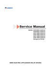
2SHUDWLRQ&KDUDFWHULVWLF&XUYH
Cooling
Heating
8
10
9
7
8
6
12K
12K
7
5
Current(A)
Current(A)
6
09K
5
4
3
Condition
Indoor:DB 27 WB19
Indoor air flow: Turbo
Pipe length:5m
Voltage:230V
2
09K
4
3
Condition
Indoor:DB 20
Indoor air flow:Turbo
Pipe length:5m
Voltage:230V
2
1
1
0
0
0
20
40
60
80
100
0
120
20
Compressor Speed(rps)
40
60
80
100
120
Compressor Speed(rps)
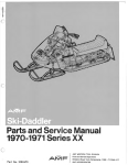
&DSDFLW\9DULDWLRQ5DWLR$FFRUGLQJWR7HPSHUDWXUH
Heating
110
120
100
100
90
80
Capacity ratio(%)
Capacity ratio(%)
Cooling
80
70
60
Condition
Indoor:DB27℃ WB19℃
Indoor air flow: Turbo
Pipe length:5m
50
32 33 34 35 36 37 38 39 40 41 42 43 44 45 46
Outdoor temp. (°C)
60
40
Condition
Indoor:DB20℃
Indoor air flow: Turbo
Pipe length:5m
20
0
-7
-5
0
5
10
Outdoor temp. (°C)
6SHFL¿FDWLRQV
2SHUDWLRQ'DWD
&RROLQJ
7HPSHUDWXUH
FRQGLWLRQ&
,QGRRU 2XWGRRU
6WDQGDUG
+HDWH[FKDQJHUSLSH
QDPH
SUHVVXUH
303D
.
.
a
WHPS
7&
7&
LQa
LQa
0RGHO
RXWa
RXWa
,QGRRUIDQ 2XWGRRUIDQ
PRGH
&RPSUHVVRU
PRGHUSP UHYROXWLRQ+]
7XUER
7XUER
+HDWLQJ
7HPSHUDWXUH
FRQGLWLRQ&
,QGRRU 2XWGRRU
6WDQGDUG
+HDWH[FKDQJHUSLSH
QDPH
SUHVVXUH
303D
.
.
a
WHPS
7&
7&
LQa
LQa
0RGHO
RXWa
RXWa
,QGRRUIDQ 2XWGRRUIDQ
&RPSUHVVRU
PRGH
PRGHUSP
UHYROXWLRQ+]
7XUER
7XUER
7,QOHWDQGRXWOHWSLSHWHPSHUDWXUHRIHYDSRUDWRU
7,QOHWDQGRXWOHWSLSHWHPSHUDWXUHRIFRQGHQVHU
33UHVVXUHRIDLUSLSHFRQQHFWLQJLQGRRUDQGRXWGRRUXQLWV
127(6
0HDVXUHVXUIDFHWHPSHUDWXUHRIKHDWH[FKDQJHUSLSHDURXQGFHQWHURIKHDWH[FKDQJHUSDWK8
EHQW7KHUPLVWRUWKHPRPHWHU
&RQQHFWLQJSLSLQJFRQGLWLRQP
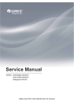
1RLVH&ULWHULD&XUYH7DEOHVIRU%RWK0RGHOV
Indoor side noise when blowing
54
45
Heating
52
12K
Noise dB(A)
Noise dB(A)
50
35
48
46
Cooling
44
09K
42
25
40
Low
Middle
Indoor fan motor rotating speed
High
20
30
40
50
60
Compressor frequency(Hz)
70
80
&RQVWUXFWLRQ9LHZV
&RQVWUXFWLRQ9LHZV
,QGRRU8QLW
*:+5$.'1$%,*:+5$.'1$%,
*:+5$.'1$$,*:+5%.'1$%,
*:+5%.'1$%,*:+5%.'1$%,
8QLWPP
&RQVWUXFWLRQ9LHZV
2XWGRRU8QLW
712
540
257
320
776
286
510
8QLWPP
5HIULJHUDQW6\VWHP'LDJUDP
5HIULJHUDQW6\VWHP'LDJUDP
INDOOR UNIT
OUTDOOR UNIT
4-Way valve
HEAT
EXCHANGER
(EVAPORATOR)
Accumlator
Compressor
HEAT
EXCHANGER
(EVAPORATOR)
Strainer
Capillary
Strainer
COOLING
HEATING
5HIULJHUDQWSLSHGLDPHWHU
/LTXLGPP
*DVPP
6FKHPDWLF'LDJUDP
6FKHPDWLF'LDJUDP
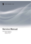
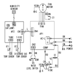
(OHFWULFDO:LULQJ
(OHFWULFDO'DWD
Symbol
Color symbol
Symbol
Parts name
BU
BLUE
COMP
COMPRESSOR
YE
YELLOW
CT12
OVERLOAD
4V
RD
RED
OG
ORANGE
BN
BROWN
BK
BLACK
YEGN
YELLOW GREEN
WH
WHITE
4-WAY VALVE
PROTECTIVE EARTH
ELECTRONIC
EXPANSION VALVE
EKV
,QGRRU8QLW
0
RT1
DISPLAY
TUBE
TEM.SENSOR
L1
AP1
CN1 CN2
0
RT2
L1
DISP-1
TUBE
DISP-2
COM-OUT
W1 BU
W2 BK
W3 BN
CAP
AP2
AC-L
W4 YEGN
EVAPORATOR
PE
SWING-UD
HEALTH-L HEALTH-N
M
M
RD
BU
COOL PLASMA
GENERATOR
YEGN
FAN MOTOR
SWING MOTOR(U.D)
PE
L
N
XT1
N(1)
2
3
L-OUT
K4
JUMP
PGF PG
POWER
13
N
ROOM
BN
YEGN
BU
OUTDOOR UNIT
ROOM
TEM.SENSOR
6FKHPDWLF'LDJUDP
2XWGRRU8QLW
*:+5$.'1$$2&%:
ROOM DISCHARGE
TUBE
TEMP. TEMP. TEMP.
SENSOR SENSOR SENSOR
W8 YEGN
RT1
0
PE
W9
YEGN
XT
INDOOR UNIT
BU
N(1)
BK
2
BN
3
YEGN
RT3
0
RT2
0
L3
CN2
CN1
L1
L4
N
W2 BK
W3 BN
L4
COM-OUT
L1
L4
AC-L
4V
CN3
N1
W6 BU
AC-N
W5 BN
AC-N2
AC-L
OVC-COMP
V W
W13 W14 W15
BU YE RD
PE
W12
BU
OFAN
U
CLAPBOARD
SUB-ASSY
ELECTRICAL BOX
AC-L3
AC-N1
AP2
AC-L1
PE
L3
W11 BN
W10 BU
LX1-1 LX1-2
W21
AC-L2
BN
E
W7
PE
AP1
W1 BU
L REACTOR
4YV
HEAT-L
HEAT-N1
W22
RD
HEAT-N2
EH1
EH2
PE
W20
L2 L2 L2
W16 W17 W18
BU YE RD
YEGN
W19 YEGN
V
U
BOTTOM BAND
HEATER
M
SAT
W
COMP.BAND
HEATER
FAN MOTOR
YEGN
PE
OVERLOARD
PROTECTOR
OUTDOOR UNIT
COMP.
PE
COMP.
*:+0$.'1$%2&%:
*:+0%.'1$%2&%:
ROOM DISCHARGE
TUBE
TEMP. TEMP. TEMP.
SENSOR
SENSOR
SENSOR
RT1
0
PE
RT3
0
RT2
0
L3
W9
YEGN
INDOOR UNIT
BU
BK
BN
YEGN
XT
W1 BU
N(1)
L1
2
3
AP1
PE
W23 BN
AC-L1
AC-L
L1
N1
W5 BN
W6 BU
W2 BK
PE
W24 BU
CLAPBOARD
SUB-ASSY
ELECTRICAL BOX
PE
L3
W10 BU W11 BN
LX1-1 LX1-2
N
W3 BN
REACTOR
L
4YV
CN2
AC-L5
AC-L4
AC-L
4V
AC-L2
AC-L3
AC-N1
AP2
AC-N
COMU
AC-N3 OVC-COMP
U V W
W13 W14 W15 W22
BU YE RD
RD
W21
BN
AC-N2
W12
BU
OFAN
HEAT-L
HEAT-N1
EH2
HEAT-N2
EH1
PE
YEGN
W19 YEGN
W20
BOTTOM BAND COMP.BAND
L2 L2 L2
M
HEATER
HEATER
SAT
W16 W17 W18
FAN MOTOR
BU YE RD
YEGN
OVERLOARD
V W
PE
PROTECTOR
U
COMP
OUTDOOR UNIT
PE
COMP.
6FKHPDWLF'LDJUDP
*:+0$.'1$%2&%:
*:+0%.'1$%2&%:
TUBE ROOM DISCHARGE
TEMP. TEMP. TEMP.
SENSOR SENSOR SENSOR
RT1
0
XT
INDOOR UNIT
BU
W1 BU
N(1)
BK
2
3
BN
YEGN
W9
YEGN
PE
AP1
L1
L4
W3 BN
L4
L1
L4
W23 BN
AC-L1
PE
L4
ELECTRICAL BOX
PE
L3
L3
W5 BN
CN2
AC-L5
AC-L4
AC-L
W6 BU AC-N
W2 BK COMU
W24 BU AC-N3
U V W
CLAPBOARD
W13 W14 W15
BU YE RD
SUB-ASSY
4V
AC-L2
AP2
AC-L3
AC-N1
N1
AC-N2
OVC-COMP
W21
BN
W12
BU
OFAN
W22
RD
PE
YEGN
W19 YEGN
W20
L2 L2 L2
W16 W17 W18
BU YE RD
WARNING
Please don't touch any terminal when
the voltage of terminal DC+ and DC- at
AP2 is higher than 30V to prevent the
risk of electrical shock!
4YV
RT3
0
W10 BU W11 BN
LX1-1 LX1-2
N
AC-L
RT2
0
REACTOR
L
V
U
PE
W
SAT
M
FAN MOTOR
OVERLOARD
PROTECTOR
YEGN
PE
COMP
COMP.
7KHVHFLUFXLWGLDJUDPVDUHVXEMHFWWRFKDQJHZLWKRXWQRWLFHSOHDVHUHIHUWRWKHRQHVXSSOLHGZLWKWKHXQLW
6FKHPDWLF'LDJUDP
3ULQWHG&LUFXLW%RDUG
,QGRRUXQLW
TOP VIEW
Solid-state relay
Port of neutral wire
Auto button Feedback of indoor fan
Live wire of health function
Port of indoor fan
Port of motor for vertical swing
Port of motor for
horizontal swing
Protective
tube
Buzzer
Port of indoor ambient
temp sensor
Port of indoor pipe
temp sensor
Power of
switch
Port of display
High-frequency transformer
Communication port
Main chip
BOTTOM VIEW
6FKHPDWLF'LDJUDP
2XWQGRRUXQLW
*:+5$.'1$$2&%:
Ɣ7239,(:
inductance pin1
inductance pin2
fan neilsbed four-way valve
compressor
electric heater
chassis e ectric heater
10-core communication cable
compressor
Ɣ%277209,(:
temp. sensor overload protection
electric expansion valve
6FKHPDWLF'LDJUDP
*:+0$.'1$%2&%:*:+0%.'1$%2&%:
*:+0$.'1$%2&%:*:+0%.'1$%2&%:
Ɣ7239,(:
inductance pin1
inductance pin2
fan
four-way valve
compressor
electric heater chassis e ectric heater
communication cable
compressor
temp. sensor
low pressure valve
overload
protection
electric expansion valve
Ɣ%277209,(:
)XQFWLRQDQG&RQWURO
)XQFWLRQDQG&RQWURO
5HPRWH&RQWURO2SHUDWLRQV
1
ON/OFF
Press it to start or stop operation.
2
Press it to decrease temperaturesetting.
3
+
Press it to increase temperaturesetting.
4
• •
MODE
Press it to select operation mode(AUTO/COOL/DRY/FAN/HEAT).
1
5
FAN
Press it to set fan speed.
3
2
6
SWING
Press it to set swing angle.
7
I FEEL
8
4
Press it to set HEALTH or AIR function.
5
6
9
10
7
8
9
10
11
11
SLEEP
TEMP
TIMER ON
Press it to set auto-on timer.
12
CLOCK
Press it to set clock function.
12
13
13
14
16
14
TIMER OFF
Press it to set auto-off timer.
15
15
TURBO
LIGHT
Press it to turn on/off the light.
16
X-FAN
25
17
24
23
22
18 19 20 21
17
MODE icon:
If MODE button is pressed,current operation mode icon
pumpmodels) will show.
18
SLEEP icon :
19
LIGHT icon:
20
TEMP icon:
(AUTO),
( COOL),
(DRY),
(FAN) or
(HEAT only for heat
is displayed by pressing the SLEEP button. Press this button again to clear the display.
is displayed by pressing the LIGHT button. Press LIGHT button again to clear the display.
Pressing TEMP button,
circularly.
21
(set temperature),
(indoor ambient temperature),
(outdoor ambient temperature) and blank is displayed
Up & down swing icon:
is displayed when pressing the up & down swing down button. Press this button again to clear the display.
)XQFWLRQDQG&RQWURO
22
LOCK icon:
is displayed by pressing "+" and “-” buttons simultaneously. Press them again to clear the display.
23
SET TIME display:
After pressing TIMER button,ON or OFF will blink.This area will show the set time.
24
DIGITAL display:
This area will show the set temperature. In SAVE mode,"SE" will be displayed.
25
AIR icon:
is displayed when pressing the AIR button.Press this button again to clear the display.
30
29
28
31
26
27
26
HEALTH icon:
is displayed when pressing the HEALTH button.Press this button again to clear the display.
27
X-FAN icon:
28
TURBO icon:
29
FAN SPEED display:
is displayed when pressing the X-FAN button. Press this button again to clear the display.
is displayed when pressing the TURBO button.Press this button again to clear the display.
Press FAN button to select the desired fan speed setting(AUTOLow-Med-High).Your selection will be displayed in the LCD windows,
except the AUTO fan speed.
30
I FEEL icon:
is displayed when pressing the I FEEL button.Press this button again to clear the display.
31
8℃ Heating icon:
is displayed when Pressing “TEMP” and “CLOCK” simultaneously in Heat mode.
1
Remote Controller Description
ON/OFF :
Press this button to turn on the unit. Press this button again to turn off the unit.
2
-:
Press this button to decrease set temperature. Hold it down for above 2 seconds to rapidly decrease set temperature. In AUTO mode,
set temperature is not adjustable.
3
+:
Press this button to increase set temperature. Hold it down for above 2 seconds to rapidly increase set temperature. In AUTO mode,
set temperature is not adjustable.
4
MODE :
Each time you press this button, a mode is selected in a sequence that goes from AUTO, COOL,DRY, FAN,and HEAT *, as the following:
AUTO
COOL
DRY
FAN
HEAT*
*Note:Only for models with heating function.
After energization, AUTO mode is defaulted. In AUTO mode, the set temperature will not be displayed on the LCD, and the unit will
automatically select the suitable operation mode in accordance with the room temperature to make indoor room comfortable.
5
FAN :
This button is used for setting Fan Speed in the sequence that goes from AUTO,
to
then back to Auto.
Auto
Low speed
Medium speed
High speed
)XQFWLRQDQG&RQWURO
6
SWING:
Press this button to set up & down swing angle, which circularly changes as below:
OFF
This remote controller is universal. If any command
,
or
is sent out,the unit will carry out the command as
indicates the guide louver swings as:
7
I FEEL:
Press this button to turn on I FEEL function. The unit automatically adjust temperature according to the sensed temperature. Press this
button again to cancel I FEEL function.
8
/
Press this button to achieve the on and off of healthy and scavenging functions in operation status. Press this button for the first time to
start scavenging function; LCD displays“
”. Press the button for the second time to start healthy and scavenging functions simultaneously; LCD displays“
” and “
” . Press this button for the third time to quit healthy and scavenging functions simultaneously. Press
the button for the fourth time to start healthy function; LCD display “
”. Press this button again to repeat the operation above.
9
SLEEP:
Press this button to go into the SLEEP operation mode. Press it again to cancel this function. This function is available in COOL , HEAT
(Only for models with heating function) or DRY mode to maintain the most comfortable temperature for you.
10
TEMP:
Press this button, could select displaying the indoor setting temperature or indoor ambient temperature.When the indoor unit firstly power
on it will display the setting temperature, if the temperature's displaying status is changed from other status to"
",displays the
ambient temperature, 5s later or within 5s, it receives other remote control signal that will return to display the setting temperature. if the
users haven't set up the temperature displaying status,that will display the setting temperature.
11
TIMERON :
Press this button to initiate the auto-ON timer. To cancel the auto-timer program, simply press this button again.
After press of this button,
disappear sand " ON " blinks .00:00 is displayed for ON time setting. Within 5 seconds, press + or - button
to adjust the time value. Every press of either button changes the time setting by 1 minute. Hold down either button to rapidly change the
time setting by 1 minute and then 10 minutes. Within 5 seconds after setting, press TIMER ON button to confirm.
12
CLOCK :
Press CLOCK button,
blinking. Within 5 seconds, pressing + or - button adjusts the present time. Hold down either button for above
2 seconds to increase or decrease the time by 1 minute every 0.5 second and then by 10 minutes every 0.5 second. During blinking after
setting, press CLOCK button again to confirm the setting, and then
will be constantly displayed.
13
TIMER OFF :
Press this button to initiate the auto-off timer. To cancel the auto-timer program, simply press the button again. TIMER OFF setting is the
same as TIMER ON.
14
TURBO:
Press this button to activate / deactivate the Turbo function which enables the unit to reach the preset temperature in the shortest time. In
COOL mode, the unit will blow strong cooling air at super high fan speed. In HEAT mode, the unit will blow strong heating air at super high
fan speed.
15
LIGHT:
Press LIGHT button to turn on the display's light and press this button again to turn off the display 's light. If the light is turned on ,
displayed. If the light is turned off,
disappears.
16
is
X-FAN:
Pressing X-FAN button in COOL or DRY mode, the icon
is displayed and the indoor fan will continue operation for 10 minutes in order
to dry the indoor unit even though you have turned off the unit.
After energization, X-FAN OFF is defaulted. X-FAN is not available in AUTO, FAN or HEAT mode.
17
Combination of "+" and "-" buttons: About lock
Press "+ " and "-" buttons simultaneously to lock or unlock the keypad. If the remote controller is locked,
is displayed. In this case,
pressing any button,
blinks three times.
18 Combination of "MODE " and "-" buttons : About switch between Fahrenheit and centigrade At unit OFF, press "MODE" and "- "
buttons simultaneously to switch between ℃ an d ℉ .
19
Combination of " TEMP " and "CLOCK" buttons : About Energy-saving Function
Press “TEMP” and “CLOCK” simultaneously in COOL mode to start energy-saving function. Nixie tube on the remote controller displays
“SE”. Repeat the operation to quit the function.
20
Combination of " TEMP " and "CLOCK" buttons : About 8℃ Heating Function
)XQFWLRQDQG&RQWURO
Press “TEMP” and “CLOCK” simultaneously in HEAT mode to start 8℃ Heating Function Nixie tube on the remote controller displays “
and a selected temperature of “ 8℃”. (46 if Fahrenheit is adopted). Repeat the operation to quit the function.
21
”
About Back-lighting Function
The unit lights for 4s when energizing for the first time, and 3s for later press.
Replacement of Batteries
1.Remove the battery cover plate from the rear of the remote controller.
(As shown in the figure)
2.Take out the old batteries.
3.Insert two new AAA1.5V dry batteries, and pay attention to the polarity.
4. Reinstall the battery cover plate.
★Notes:
●When replacing the batteries, do not use old or different types of batteries,
otherwise, it may cause malfunction.
●If the remote controller will not be used for a long time, please
remove batteries to prevent batteries from leaking.
●The operation should be performed in its receiving range.
●It should be kept 1m away from the TV set or stereo sound sets.
●If the remote controller does not operate normally, please take the
batteries out and reinsert them after 30 seconds.If it still can't operate properly,
replace the batteries.
Sketch map for
replacing batteries
)XQFWLRQDQG&RQWURO
'HVFULSWLRQRI(DFK&RQWURO2SHUDWLRQ
1. Temperature Parameters
Indoor preset temperature (Tpreset)
Indoor ambient temperature (T amb.)
2. Basic Functions
Once energized, in no case should the compressor be restarted within less than 3 minutes. In the situation that memory
function is available, for the first energization, if the compressor is at stop before de-energization, the compressor will be
started without a 3-minute lag; if the compressor is in operation before de-energization, the compressor will be started with
a 3-minute lag; and once started, the compressor will not be stopped within 6 minutes regardless of changes in room
temperature;
(1)COOL mode
The condition and process of cooling
If Tamb. ≥Tpreset COOL mode will act, the compressor and outdoor fan will run, and the indoor fan will run at the set speed.
If Tamb. ≤Tpreset-2 , the compressor will stop, the outdoor fan will delay 30 seconds to stop, and the indoor fan will run at the set speed.
If Tpreset-2
≤Tamb ≤Tpreset , the unit will keep running in the previous mode.
In this mode, the reversal valve will not be powered on and the temperature setting range is 16
~30 .
Start cooling
Tamb.
Tpreset +1 ˚C
Original operating status
Tpreset –1 ˚C
≥ 6 min.
≥ 3 min.
≥ 6 min.
Stop cooling
Compressor
Outdoor fan
Setting fan speed
Indoor fan
Run
Protection function
Overcurrent protection
Stop
If total current is high, the compressor will run in limited frequency. If total current is too high, the compressor will stop, the
outdoor fan will delay 30 seconds to stop, indoor unit will display E5 and outdoor yellow light will blink 5 times.
Antifreezing protection
When the antifreezing protection is detected, the compressor will stop, the outdoor fan will stop after 30 seconds, and the
indoor fan and swing motor will keep running in the original mode. When antifreezing protection is eliminated and the
compressor has stopped for 3 minutes, the compressor will resume running in the original mode.
During antifreeze protection
min
Compressor
Outdoor fan
Preset speed
Indoor fan
Run
Stop
(2) Dehumidifying Mode
Working conditions and process of dehumidifying
If T amb. T preset, the unit will enter cooling and dehumidifying mode, in which case the compressor and the outdoor fan will
operate and the indoor fan will run at low speed.
If T preset -2
T amb. T preset, the compressor remains at its original operation state.
If T amb.< T preset -2 , the compressor will stop, the outdoor fan will stop with a time lag of 30s, and the indoor fan will
operate at low speed.
Protection
Protection is the same as that under the cooling mode.
)XQFWLRQDQG&RQWURO
(3) HEAT mode
The condition and process of heating
If Tamb≤Tpreset+2
, HEAT mode will act, the compressor, outdoor fan and reversal valve will run, the indoor fan will delay
3min to stop at the latest
If Tpreset +2
Tamb Tpreset +5
If Tamb≥Tpreset +5
,the unit will keep running in the original mode.
, the compressor will stop, the outdoor fan will delay 30sec to stop and indoor fan will blow 60S at low
speed, the fan speed cannot be shifted within blow residual heat.
In this mode, the temperature setting range is 16
~30
.
The air conditioner will adjust the running frequency of the compressor automatically according to the change of ambient
temperature.
When the unit is turned off in HEAT mode, or switched to other mode from HEAT mode, the four-way valve will be powered
off after the compressor stops.
Stop heating
Tpreset+4
Original operating status
Tpreset+2
Tamb.
min.
min.
min.
Start heating
Compressor
Outdoor fan
Indoor fan
preset wind
min.
min.
preset wind
Reversing valve
Run
Stop
The condition and process of defrosting
When frost is detected in the condenser, the system will enter into defrosting state. When defrosting starts, the compressor and
indoor fan will stop, and the outdoor fan and four-way valve will delay 30 seconds to stop. The compressor will start after 15 seconds
and then defrosting will be started. When the compressor has run for 7 minutes or defrosting is finished, the compressor will stop.
After 30 seconds the four-way valve opens and after another 60 seconds, the compressor and outdoor fan resume running. The
indoor fan will delay 3 minutes to run at the latest and temperature on the display panel shows H1.
The period of defrosting
30s
30s
Four-way valve
Compressor
15s
7min
60s
30s
Outdoor Unit
Indoor Unit
3min Set fan speed
Run
Stop
Protection function
Anti-cold-wind protection
In HEAT mode, in order to prevent the indoor unit from blowing out cold wind, each time the compressor starts, the indoor fan
will delay 3 minutes after the compressor to run at the latest and it can adjust fan speed automatically when temperature is low.
Overcurrent protection
Overcurrent protection is the same with that in COOL mode.
3.Protection
Cold air prevention
The unit is started under heating mode (the compressor is ON):
In the case of Tindoor amb. <24 : if T tube 40 and the indoor fan is at stop state, the indoor fan will begin to run at low
speed with a time lag of 2 minutes. Within 2 minutes, if T tube 40 , the indoor fan also will run at low speed; and after
1-minute operation at low speed, the indoor fan will be converted to operation at preset speed.Within 1-minute low speed
operation or 2-minute non-operation, if T tube 42 , the fan will run at present speed.
In the case of T indoor amb. 24 : if T tube 42 , the indoor fan will run at low speed, and after one minute, the indoor fan
will be converted to preset speed. Within one-minute low speed operation, if T tube 42 , the indoor fan will be converted
to preset speed.
)XQFWLRQDQG&RQWURO
Note: Tindoor amb. indicated in 1 and 2 refers to, under initially heating mode, the indoor ambient temperature before the
command to start the compressor is performed according to the program, or after the unit is withdrawn from defrost, the
indoor ambient temperature before the defrost symbol is cleared.
Total current up and frequency down protection
If the total current Itotal W, frequency rise will be allowed; if I total X, frequency rise will not be allowed; if I total Y, the compressor
will run at reduced frequency; and if I total Z, the compressor will stop and the outdoor fan will stop with a time lag of 30s.
(4) Fan Mode
Under the mode, the indoor fan will run at preset speed and the compressor, the outdoor fan, the four-way valve and the
electric heater will stop.
Under the mode, temperature can be set within a range of 16 - 30 .
(5) AUTO Mode
a. When Tamb.26ć, the unit will operate under cooling mode, while the implied setting temperature is 25ć.
b. When Tamb.22ć, the heat pump unit will operate under heating mode, while the implied setting temperature is 20ć; the cooling only unit will operate under
fan mode, while the displaying setting temperature is 25ć.
c. When 23ćTamb.25ć, the unit will operate as previous mode. If it is the first time energized, the unit will operate under fan mode.
d. When the unit is operating under auto mode, the compressor frequency is the same as cooling/heating mode when the unit is under cooling/heating operation.
2.Protection
a. In cooling operation, protection is the sam e as that under the cooling mode;
b. In heating operation, protection is the same as that under the heating mode;
c. When ambient temperature changes, operation mode will be converted preferentially. Once started, the compressor will
remain unchanged for at least 6 minutes.
(6) Common Protection Functions and Fault Display under COOL, HEAT, DRY and AUTO Modes
Overload protection
T tube: measured temperature of outdoor heat exchanger under cooling mode; and measured temperature of indoor heat
exchanger under heating mode.
1) Cooling overload
a. If T tube 52 , the unit will return to its original operation state.
b. If T tube 55 , frequency rise is not allowed.
c. If T tube 58 , the compressor will run at reduced frequency.
d. If T tube 62 , the compressor will stop and the indoor fan will run at preset speed.
2) Heating overload
a. If T tube 52 , the unit will return to its original operation state.
b. If T tube 55 , frequency rise is not allowed.
c. If T tube 58 , the compressor will run at reduced frequency.
d. If T tube 62 , the compressor will stop and the indoor fan will blow residue heat and then stop.
Exhaust temperature protection of compressor
If exhaust temperature 98 , frequency is not allowed to rise.
If exhaust temperature 103 , the compressor will run at reduced frequency.
If exhaust temperature 110 , the compressor will stop.
If exhaust temperature 90 and the compressor has stayed at stop for at least 3 minutes, the compressor will resume its
operation.
Communication fault
If the unit fails to receive correct signals for durative 3 minutes, communication fault can be justified and the whole system
will stop.
Module protection
Under module protection mode, the compressor will stop. When the compressor remains at stop for at least 3 minutes, the
compressor will resume its operation. If module protection occurs six times in succession, the compressor will not be started
again.
Overload protection
If temperature sensed by the overload sensor is over 115 , the compressor will stop and the outdoor fan will stop with a
time lag of 30 seconds. If temperature is below 95 , the overload protection will be relieved.
If voltage on the DC bus is below 150V or over 420V, the compressor will stop and the outdoor fan will stop with a time
lag of 30 seconds. When voltage on the DC bus returns to its normal value and the compressor has stayed at stop for at least
3 minutes, the compressor will resume its operation.
Faults of temperature sensors
)XQFWLRQDQG&RQWURO
Designation of sensors
Indoor ambient temperature
Indoor tube temperature
Outdoor ambient temperature
Outdoor tube temperature
Exhaust
Overload
Faults
The sensor is detected to be open-circuited or short-circuited for successive 30
seconds
The sensor is detected to be open-circuited or short-circuited for successive 30
seconds
The sensor is detected to be open-circuited or short-circuited for successive 30
seconds
The sensor is detected to be open-circuited or short-circuited for successive 30
seconds, and no detection is performed within 10 minutes after defrost begins.
After the compressor has operated for 3 minutes, the sensor is detected to be
open-circuited or short-circuited for successive 30 seconds.
After the compressor has operated for 3 minutes, the sensor is detected to be
open-circuited or short-circuited for successive 30 seconds.
3. Other Controls
(1) ON/OFF
Press the remote button ON/OFF: the on-off state will be changed once each time you press the button.
(2) Mode Selection:
Press the remote button MODE, then select and show in the following ways: AUTO, COOL, DRY, FAN, HEAT, AUTO.
(3) Temperature Setting Option Button
Each time you press the remote button TEMP+ or TEMP-, the setting temperature will be up or down by 1 . Regulating
Range: 16~30 , the button is useless under the AUTO mode.
(4) Time Switch
You should start and stop the machine according to the setting time by remote control.
(5) SLEEP State Control
a. When the air conditioner is under the mode of COOL, DRY, and the SLEEP mode has been set well, after the SLEEP
state keeps about 1 hour, the pre-setting T will raise 1 , and it will raise 1
again after 2 hours, so it raise 2 in 2 hours,
then it will run on at the setting temperature and wind speed.
b. When the air conditioner is under the mode of HEAT, and the Timer has been set well, after the SLEEP state keeps about
1 hour, the pre-setting T will reduce 1 , and it will reduce 1
again after 2 hours, so it reduce 2 in 2 hours, then it will
run on at the setting temperature and wind speed.
c. The setting temperature keeps the same under the FAN mode and AUTO mode.
(6) Indoor Fan Control
Indoor fan could be set at ultra-high, high, medium, low speed by wireless remote controller and operated as that speed.
Auto fan speed could be set as well, indoor fan will operate under auto fan speed as following:
1. Under heating mode: auto speed under heating or auto heating mode:
a. When Tamb.Tpreset+1ć, indoor fan will operate at high speed;
b. When Tpreset+1ć˘Tamb.˘Tpreset+3ć, indoor fan will operate at medium speed;
c. When Tamb.Tpreset+3ć, indoor fan will operate at low speed;
There should be at least 180s operation time during switchover of each speed.
2. Under cooling mode: auto speed under cooling or auto cooling mode:
a. When Tamb.Tpreset+2ć, indoor fan will operate at high speed;
b. When Tpreset˘Tamb.˘Tpreset+2ć, indoor fan will operate at medium speed;
c. When Tamb.Tpreset, indoor fan will operate at low speed
There should be at least 180s operation time during switchover of each speed.
(7) Buzzer Control
The buzzer will send a “Di” sound when the air conditioner is powered up or received the information sent by the remote
control or there is a button input, the single tube cooler doesn’t receive the remote control ON signal under the mode of
heating mode.
(8) Auto button
If the controller is on, it will stop by pressing the button, and if the controller is off, it will be automatic running state by
pressing the button, swing on and light on, and the main unit will run based on the remote control if there is remote control
order.
(9) Up-and-Down Swinging Control
When power on, the up-and-down motor will firstly move the air deflector to o counter-clockwise, close the air outlet.
After starting the machine, if you don’t set the swinging functi on, heating mode and auto-heating mode, the up-and-down
air deflector will move to D clockwise; under other modes, the up-and-down air deflector will move to L1. If you set the
swinging function when you start the machine, then the wind blade will swing between L and D. The air deflector has 7
)XQFWLRQDQG&RQWURO
swinging states: Location L, Location A, Location B, Location C, Location D, Location L to Location D, stop at any
location between L-D (the included angle between L~D is the same). The air deflector will be closed at 0 Location, and the
swinging is effectual only on condition that setting the swinging order and the inner fan is running. The indoor fan and
compressor may get the power when air deflector is on the default location.
Heating angle
O(0°)
Cooling angle
O(0°)
L
A
B
C
D
L1
A1
B1
C1
D1
(10) Display
Operation pattern and mode pattern display
All the display patterns will display for a time when the poweron, the operation indication pattern will display in red under
standby status. When the machine is start by remote control, the indication pattern will light and display the current
operation mode (the mode light includes: Cooling, heating and dehumidify). If you close the light key, all the display
patterns will close.
Double-8 display
According to the different setting of remote control, the nixie light may display the current temperature (the temperature
scope is from 16 to 30 ) and indoor ambient temperature. The heating and air supply temperature will display 25 under
auto-mode, the temperature will display 20 under the auto-heating mode, and the temperature will display H1 under the
defrosting mode.(If you set the fahrenheit temperature display, the nixie light will display according to fahrenheit
temperature)
(11) Protection function and failure display
E2: Freeze-proofing protection E4: Exhausting protecti on E5: Overcurrent protection
E6: Communication failure
F1: Indoor ambient sensor start and short circuit (continuously measured failure in 30S)
F2: Indoor evaporator sensor start and short circuit (continuously measured failure in 30S)
F3: Outdoor ambient sensor start and short circuit (continuously measured failure in 30S)
F4: Outdoor condenser sensor start and short circuit (continuously measured failure in 30S, and don’t measure within 10
minutes after defrosted)
F5: Outdoor exhausting sensor start and short circuit (continuously measured failure in 30S after the compressor operated 3
minutes)
H3: Overload protection of compressor
H5: Module protection
PH: High-voltage protection
PL: Low-voltage protection
P1: Nominal cooling and heating test
P2: Maximum cooling and heating test
P3: Medium cooling and heating test
P0: Minimum cooling and heating test
(12) Drying Function
You may start or stop the drying function under the modes of cooling and dehumidify at the starting status (The modes of
automatism, heating and air supply do not have drying function). When you start the drying function, after stop the
machine by pressing the switch button, you should keep running the inner fans for 10 minutes under low air damper (The
swing will operate as the former status within 10 minutes, and other load is stopped), then stop the entire machine; When
you stop the drying function, press the switch button will stop the machine directly.
When you start the drying function, operating the drying button will stop the inner fans and close the guide louver.
(13) Memory Function
When interrupting the power supply memory content: mode, swing function, light, set temperature and wind speed.
After interrupted the power supply, the machine will start when recovering the power according to the memory content
automatically.
,QVWDOODWLRQ0DQXDO
,QVWDOODWLRQ0DQXDO
1RWLFHVIRU,QVWDOODWLRQ
7KHXQLWLQVWDOODWLRQZRUNPXVWEHGRQHE\TXDOL¿HGSHUVRQQHODFFRUGLQJWRWKHORFDOUXOHVDQGWKLVPDQXDO
%HIRUH LQVWDOODWLQJ SOHDVH FRQWDFW ZLWK ORFDO DXWKRUL]HG PDLQWHQDQFH FHQWHU LI XQLW LV QRW LQVWDOOHG E\ WKH DXWKRUL]HG
PDLQWHQDQFHFHQWHUWKHPDOIXQFWLRQPD\QRWVROYHG
GXHWRGLVFRPPRGLRXVFRQWDFWV
:KHQUHPRYLQJWKHXQLWWRWKHRWKHUSODFHSOHDVH¿UVWO\FRQWDFWZLWKWKHDXWKRUL]HG0DLQWHQDQFH&HQWHULQWKHORFDODUHD
WKHDSSOLDQFHPXVWEHSRVLWLRQHGVRWKDWWKHSOXJLVDFFHVVLEOH
$IWHUSXOORXWWKHSRZHUSOXJWKHQPDNHWKHDSSOLDQFH RSHUDWLRQ DJDLQWR DYRLG WKH LFLQJ RI RXWGRRU XQLW GDPDJH D[LDOÀRZ
IDQVKRXOGHOHFWULI\WKHDSSOLDQFHEXWQRWRSHUDWLRQIRUKRXUVIRUZDUPXSSXUSRVH
,QVWDOODWLRQ6LWH,QVWUXFWLRQV
,QVWDOOLQWKHIROORZLQJSODFHPD\FDXVHPDOIXQFWLRQ,ILWLVXQDYRLGDEOHFRQWDFWZLWKVHUYLFHFHQWHUSOHDVH
ƔVWURQJKHDWVRXUFHVYDSRXUVÀDPPDEOHJDVRUYRODWLOHOLTXLGVDUHHPLWWHG
ƔKLJKIUHTXHQF\HOHFWURPDJQHWLFZDYHVDUHJHQHUDWHGE\UDGLRHTXLSPHQWZHOGHUVDQGPHGLFDOHTXLSPHQW
ƔVDOWODGHQDLUSUHYDLOVVXFKDVFORVHWRFRDVWDODUHDV
ƔWKHDLULVFRQWDPLQDWHGZLWKLQGXVWULDOYDSRXUVDQGRLOV
ƔWKHDLUFRQWDLQVVXOSKXUHVJDVVXFKDVLQKRWVSULQJ]RQHV
ƔFRUURVLRQRUSRRUDLUTXDOLW\H[LVWV
,QVWDOODWLRQ6LWHRI,QGRRU8QLW
7KHDLULQOHWDQGRXWOHWVKRXOGEHDZD\IURPWKHREVWUXFWLRQV(QVXUHWKHDLUFDQEHEORZQWKURXJKWKHZKROHURRP
6HOHFWDVLWHZKHUHWKHFRQGHQVDWHFDQEHHDVLO\GUDLQHGRXWDQGZKHUHLWLVHDVLO\FRQQHFWHGWRRXWGRRUXQLW
6HOHFWDSODFHZKHUHLWLVRXWRIUHDFKRIFKLOGUHQ
6HOHFWDSODFHZKHUHWKHZDOOLVVWURQJHQRXJKWRZLWKVWDQGWKHIXOOZHLJKWDQGYLEUDWLRQRIWKHXQLW
%HVXUHWROHDYHHQRXJKVSDFHWRDOORZDFFHVVIRUURXWLQHPDLQWHQDQFH7KHLQVWDOODWLRQVLWHVKRXOGEHFPRUPRUHDERYH
WKHÀRRU
6HOHFWDSODFHDERXWPRUPRUHDZD\IURP79VHWRUDQ\RWKHUHOHFWULFDSSOLDQFH
6HOHFWDSODFHZKHUHWKH¿OWHUFDQEHHDVLO\WDNHQRXW
0DNHVXUHWKDWWKHLQGRRUXQLWLVLQVWDOOHGLQDFFRUGDQFHZLWKLQVWDOODWLRQGLPHQVLRQLQVWUXFWLRQV
'RQRWXVHWKHXQLWLQWKHODXQGU\RUE\VZLPPLQJSRROHWF
,QVWDOODWLRQ6LWHRI2XWGRRU8QLW
6HOHFWDVLWHZKHUHQRLVHDQGRXWÀRZDLUHPLWWHGE\WKHXQLWZLOOQRWDQQR\QHLJKERUV
6HOHFWDVLWHZKHUHWKHUHLVVXI¿FLHQWYHQWLODWLRQ
6HOHFWDVLWHZKHUHWKHUHLVQRREVWUXFWLRQEORFNLQJWKHLQOHWDQGRXWOHW
7KHVLWHVKRXOGEHDEOHWRZLWKVWDQGWKHIXOOZHLJKWDQGYLEUDWLRQ
6HOHFWDGU\SODFHEXWGRQRWH[SRVHWKHXQLWWRGLUHFWVXQOLJKWRUVWURQJZLQG
0DNHVXUHWKDWWKHRXWGRRUXQLWLVLQVWDOOHGLQDFFRUGDQFHZLWKWKHLQVWDOODWLRQLQVWUXFWLRQVDQGLVFRQYHQLHQWIRUPDLQWHQDQFH
DQGUHSDLU
7KHKHLJKWGLIIHUHQFHEHWZHHQLQGRRUDQGRXWGRRUXQLWVLVZLWKLQPDQGWKHOHQJWKRIWKHFRQQHFWLQJWXELQJGRHVQRWH[FHHG
P.RUP.
6HOHFWDSODFHZKHUHLWLVRXWRIUHDFKRIFKLOGUHQ
6HOHFWDSODFHZKHUHWKHXQLWGRHVQRWKDYHQHJDWLYHLPSDFWRQSHGHVWULDQVRURQWKHFLW\
,QVWDOODWLRQ0DQXDO
6DIHW\3UHFDXWLRQVIRU(OHFWULF$SSOLDQFHV
$GHGLFDWHGSRZHUVXSSO\FLUFXLWVKRXOGEHXVHGLQDFFRUGDQFHZLWKORFDOHOHFWULFDOVDIHW\UHJXODWLRQV
'RQ
WGUDJWKHSRZHUFRUGZLWKH[FHVVLYHIRUFH
7KHXQLWVKRXOGEHUHOLDEO\HDUWKHGDQGFRQQHFWHGWRDQH[FOXVLYHHDUWKGHYLFHE\WKHSURIHVVLRQDOV
7KHDLUVZLWFKPXVWKDYHWKHIXQFWLRQVRIPDJQHWLFWULSSLQJDQGKHDWWULSSLQJWRSUHYHQWVKRUWFLUFXLWDQGRYHUORDG
7KHPLQLPXPGLVWDQFHEHWZHHQWKHXQLWDQGFRPEXVWLYHVXUIDFHLVP
7KHDSSOLDQFHVKDOOEHLQVWDOOHGLQDFFRUGDQFHZLWKQDWLRQDOZLULQJUHJXODWLRQV
$QDOOSROHGLVFRQQHFWLRQVZLWFKZLWKDFRQWDFWVHSDUDWLRQRIDWOHDVWPPLQDOOSROHVVKRXOGEHFRQQHFWHGLQ¿[HGZLULQJ
1RWH
Ɣ0DNHVXUHWKHOLYHZLUHQHXWUDOZLUHDQGHDUWKZLUHLQWKHIDPLO\SRZHUVRFNHWDUHSURSHUO\FRQQHFWHG
Ɣ7KHUHVKRXOGEHUHOLDEOHFLUFXLWLQWKHGLDJUDP,QDGHTXDWHRULQFRUUHFWHOHFWULFDOFRQQHFWLRQVPD\FDXVHHOHFWULFVKRFNRU¿UH
(DUWKLQJ5HTXLUHPHQWV
$LUFRQGLWLRQHULVW\SH,HOHFWULFDSSOLDQFH3OHDVHHQVXUHWKDWWKHXQLWLVUHOLDEO\HDUWKHG
7KH\HOORZJUHHQZLUHLQDLUFRQGLWLRQHULVWKHHDUWKLQJZLUHZKLFKFDQQRWEHXVHGIRURWKHUSXUSRVHV,PSURSHUHDUWKLQJPD\
FDXVHHOHFWULFVKRFN
7KHHDUWKUHVLVWDQFHVKRXOGDFFRUGWRWKHQDWLRQDOFULWHULRQ
7KHSRZHUPXVWKDYHUHOLDEOHHDUWKLQJWHUPLQDO3OHDVHGRQRWFRQQHFWWKHHDUWKLQJZLUHZLWKWKHIROORZLQJ
ķ :DWHUSLSHĸ *DVSLSHĹ &RQWDPLQDWLRQSLSHĺ 2WKHUSODFHWKDWSURIHVVLRQDOSHUVRQQHOFRQVLGHULVXQUHOLDEOH
7KHPRGHODQGUDWHGYDOXHVRIIXVHVVKRXOGDFFRUGZLWKWKHVLONSULQWRQIXVHFRYHURUUHODWHG3&%
,QVWDOODWLRQ0DQXDO
,QVWDOODWLRQ'LPHQVLRQ'LDJUDP
Space to the ceiling
15 cm
Above
Space to the wall
15 cm Above
15 cm Above
Space to the wall
300 cm
Above
250
cm
Above
Air outlet side
Space to the floor
The dimensions of the space necessary for proper
installation of the appliance include the minimum
permissible distances to adjacent structures.
Space to the obstruction
50 cm Above
●
Air inlet side
e
ov
30 cm Above
30
cm
Ab
Space to the wall
Space to the wall
50 cm Above
ve
o
m
0c
Ab
20
Air outlet side
,QVWDOODWLRQ0DQXDO
,QVWDOO,QGRRU8QLW
,QVWDOODWLRQRI0RXQWLQJ3ODWH
0RXQWLQJ SODWH VKRXOG EH LQVWDOOHG KRUL]RQWDOO\$V WKH ZDWHU WUD\
V RXWOHW IRU WKH LQGRRU XQLW LV WZRZD\ W\SH GXULQJ
LQVWDOODWLRQWKHLQGRRUXQLWVKRXOGVOLJKWO\VODQWWRZDWHUWUD\
VRXWOHWIRUVPRRWKGUDLQDJHRIFRQGHQVDWH
)L[WKHPRXQWLQJSODWHRQWKHZDOOZLWKVFUHZV
%HVXUHWKDWWKHPRXQWLQJSODWHKDVEHHQ¿[HG¿UPO\HQRXJKWRZLWKVWDQGDERXWNJ0HDQZKLOHWKHZHLJKWVKRXOG
EHHYHQO\VKDUHGE\HDFKVFUHZ
Wall
Wall
Mark on the middle of it
Space
to the
wall
150
above
Gradienter
Φ55
Space
to the
wall
150
above
Φ55
Right
Left
(Rear piping hole)
8QLWPP
(Rear piping hole)
'ULOO3LSLQJ+ROH
Outdoor
Indoor
Wall pipe
6ODQWWKHSLSLQJKROHRQWKHZDOOVOLJKWO\GRZQZDUGWRWKHRXWGRRUVLGH
ĭ
Seal pad
,QVHUWWKHSLSLQJKROHVOHHYHLQWRWKHKROHWRSUHYHQWWKHFRQQHFWLRQSLSLQJDQG
Φ55
ZLULQJIURPEHLQJGDPDJHGZKHQSDVVLQJWKURXJKWKHKROH
,QVWDOODWLRQRI'UDLQ+RVH
&RQQHFWWKHGUDLQKRVHWRWKHRXWOHWSLSHRIWKHLQGRRUXQLW%LQGWKHMRLQWZLWK
UXEEHUEHOW
3XWWKHGUDLQKRVHLQWRLQVXODWLQJWXEH
outlet pipe of
indoor unit
drain hose
outlet pipe of
indoor unit
rubber belt
:UDS WKH LQVXODWLQJ WXEH ZLWK ZLGH UXEEHU EHOW WR SUHYHQW WKH VKLIW RI LQVXODWLQJ
outlet pipe of
indoor unit
WXEH
6ODQWWKHGUDLQKRVHGRZQZDUGVOLJKWO\IRUVPRRWKGUDLQDJHRIFRQGHQVDWH
drain hose
rubber belt insulating tube
rubber belt
outlet pipe of
indoor unit
1RWH7KHLQVXODWLQJWXEHVKRXOGEHFRQQHFWHGUHOLDEO\ZLWKWKHVOHHYHRXWVLGHWKHRXWOHW
SLSH7KHGUDLQKRVHVKRXOGEHVODQWHGGRZQZDUGVOLJKWO\ZLWKRXWGLVWRUWLRQEXOJHRU
ÀXFWXDWLRQ'RQRWSXWWKHRXWOHWLQWKHZDWHU
connected
bulge
insulating tube
distortion
Flooded
&RQQHFWLQJ,QGRRUDQG2XWGRRU(OHFWULF:LUHV
2SHQWKHIURQWSDQHO
Wiring Cover
5HPRYHWKHZLULQJFRYHUFRQQHFWDQG¿[SRZHUFRQQHFWLRQFRUG
WRWKHWHUPLQDOERDUGDVVKRZQLQ)LJ
0DNHWKHSRZHUFRQQHFWLRQFRUGSDVVWKURXJKWKHKROHDWWKH
EDFNRILQGRRUXQLW
N(1)
5HLQVWDOOWKHFRUGDQFKRUDJHDQGZLULQJFRYHU
5HLQVWDOOWKHIURQWSDQHO
yellow-green
outdoor unit connection
Fig 2
3
brown
,QVWDOODWLRQ0DQXDO
127(
$OOZLUHVEHWZHHQLQGRRUDQGRXWGRRUXQLWVPXVWEHFRQQHFWHGE\WKHTXDOL¿HGHOHFWULFFRQWUDFWRU
Ɣ(OHFWULFZLUHVPXVWEHFRQQHFWHGFRUUHFWO\,PSURSHUFRQQHFWLRQPD\FDXVHPDOIXQFWLRQ
Ɣ7LJKWHQWKHWHUPLQDOVFUHZVVHFXUHO\
Ɣ$IWHUWLJKWHQLQJWKHVFUHZVSXOOWKHZLUHVOLJKWO\WRFRQ¿UPZKHWKHULWLV¿UPRUQRW
Ɣ0DNHVXUHWKDWWKHHOHFWULFFRQQHFWLRQVDUHHDUWKHGSURSHUO\WRSUHYHQWHOHFWULFVKRFN
Ɣ0DNHVXUHWKDWDOOZLULQJFRQQHFWLRQVDUHVHFXUHDQGWKHFRYHUSODWHVDUHUHLQVWDOOHGSURSHUO\3RRULQVWDOODWLRQPD\
FDXVH¿UHRUHOHFWULFVKRFN
,QVWDOODWLRQRI,QGRRU8QLW
Ɣ7KHSLSLQJFDQEHRXWSXWIURPULJKWULJKWUHDUOHIWRUOHIWUHDU
Gas side pipe
:KHQURXWLQJWKHSLSLQJDQGZLULQJIURPWKHOHIWRUULJKWVLGHRILQGRRUXQLW
FXWRIIWKHWDLOLQJVIURPWKHFKDVVLVZKHQQHFHVVDU\$VVKRZQLQ)LJ
External connection
electric wire
Liquid side piping
Tailing 2
side piping
Tailing 1 Gas
insulation
&XWRIIWDLOLQJZKHQURXWLQJWKHZLULQJRQO\
Fig.3
Liquid side
Piping insulation
Finally wrap it
Water drainage pipe
with tape
&XWRIIWDLOLQJDQGWDLOLQJZKHQURXWLQJERWKWKHZLULQJDQGSLSLQJ
7DNHRXWWKHSLSLQJIURPERG\FDVHZUDSWKHSLSLQJSRZHUFRUGVGUDLQKRVH
ZLWKWKHWDSHDQGWKHQPDNHWKHPSDVVWKURXJKWKHSLSLQJKROH$VVKRZQLQ
Left
)LJ
Left rear
Right
Fig.4
Right rear
+DQJ WKH PRXQWLQJ VORWV RI WKH LQGRRU XQLW RQ WKH XSSHU KRRNV RI WKH
Fixing hook
PRXQWLQJSODWHDQGFKHFNLILWLV¿UPHQRXJK$VVKRZQLQ)LJ
Mounting
plate
7KHLQVWDOODWLRQVLWHVKRXOGEHFPRUPRUHDERYHWKHÀRRU
Mounting
plate
Fig.5
,QVWDOODWLRQRI&RQQHFWLRQ3LSH
$OLJQWKHFHQWHURIWKHSLSHÀDUHZLWKWKHUHODWHGYDOYH
6FUHZ LQ WKH IODUH QXW E\ KDQG DQG WKHQ WLJKWHQ WKH QXW ZLWK VSDQQHU DQG
WRUTXHZUHQFKE\UHIHUULQJWRWKHIROORZLQJ
Hex nut diameter
Tightening torque
Ф6.35
Ф9.52
Ф12.7
Ф15.88
Ф19.05
15
31
50
60
70
(N·m)
Indoor unit piping
20
35
55
65
75
Taper nut Piping
Spanner
Torque
wrench
127(&RQQHFWWKHFRQQHFWLRQSLSHWRLQGRRUXQLWDW¿UVWDQGWKHQWRRXWGRRUXQLW
+DQGOHSLSLQJEHQGLQJZLWKFDUH'RQRWGDPDJHWKHFRQQHFWLRQSLSH(QVXUHWKDW
WKHMRLQWQXWLVWLJKWHQHG¿UPO\RWKHUZLVHLWPD\FDXVHOHDNDJH
,QVWDOO2XWGRRU8QLW
(OHFWULF:LULQJ
5HPRYHWKHKDQGOHRQWKHULJKWVLGHSODWHRIRXWGRRUXQLW
7DNHRIIZLUHFRUGDQFKRUDJH&RQQHFWDQG¿[SRZHUFRQQHFWLRQFRUG
WRWKHWHUPLQDOERDUG:LULQJVKRXOG¿WWKDWRILQGRRUXQLW
)L[ WKH SRZHU FRQQHFWLRQ FRUG FODPSV DQG WKHQ FRQQHFW WKH
FRUUHVSRQGLQJFRQQHFWRU
&RQ¿UPLIWKHZLUHKDVEHHQ¿[HGSURSHUO\
5HLQVWDOOWKHKDQGOH
Handle
N(1) 2
3
blue black brown
yellowgreen
Indoor unit
connection
127(
Ɣ,QFRUUHFWZLULQJPD\FDXVHPDOIXQFWLRQRIVSDUHSDUW
Ɣ$IWHUWKHZLUHKDVEHHQ¿[HGHQVXUHWKHUHLVIUHHVSDFHEHWZHHQWKHFRQQHFWLRQDQG¿[LQJSODFHVRQWKHOHDGZLUH
6FKHPDWLFGLDJUDPEHLQJUHIHUHQFHRQO\SOHDVHUHIHUWRUHDOSURGXFWIRUDXWKHQWLFLQIRUPDWLRQ
,QVWDOODWLRQ0DQXDO
$LU3XUJLQJDQG/HDNDJH7HVW
&RQQHFWFKDUJLQJKRVHRIPDQLIROGYDOYHWRFKDUJHHQGRIORZSUHVVXUH
YDOYHERWKKLJKORZSUHVVXUHYDOYHVPXVWEHWLJKWO\VKXW
Liquid pipe
Vacuum
gauge
Gas pipe
&RQQHFWMRLQWRIFKDUJLQJKRVHWRYDFXXPSXPS
Valve
cap
)XOO\RSHQWKHKDQGOHRI/RPDQLIROGYDOYH
2SHQ WKH YDFXXP SXPS IRU YDFXXPL]DWLRQ$W WKH EHJLQQLQJ VOLJKWO\
ORRVHQMRLQWQXWRIORZSUHVVXUHYDOYHWRFKHFNLIWKHUHLVDLUFRPLQJLQVLGH,I
QRLVHRIYDFXXPSXPSKDVEHHQFKDQJHGWKHUHDGLQJRIPXOWLPHWHULV
7KHQWLJKWHQWKHQXW
Vacuum pump
.HHS YDFXXPLQJ IRU PRUH WKDQ PLQV DQG PDNH VXUH WKH UHDGLQJ RI
PXOWLPHWHULV;SDFP+J
)LJ
)XOO\RSHQKLJKORZSUHVVXUHYDOYHV
5HPRYHFKDUJLQJKRVHIURPFKDUJLQJHQGRIORZSUHVVXUHYDOYH
7LJKWHQOLGRIORZSUHVVXUHYDOYH$VVKRZQLQ)LJ
2XWGRRU&RQGHQVDWH'UDLQDJHRQO\IRUKHDWSXPSXQLW
'XULQJ KHDWLQJ RSHUDWLRQ WKH FRQGHQVDWH DQG GHIURVWLQJ ZDWHU VKRXOG EH
Drain-water hole
Bottom frame
GUDLQHGRXWUHOLDEO\WKURXJKWKHGUDLQKRVH,QVWDOOWKHRXWGRRUGUDLQFRQQHFWRU
LQDĭKROHRQWKHEDVHSODWHDQGDWWDFKWKHGUDLQKRVHWRWKHFRQQHFWRUVR
WKDWWKHZDVWHZDWHUIRUPHGLQWKHRXWGRRUXQLWFDQEHGUDLQHGRXW7KHKROH
Drain connecter
Hose (available commercially,
inner dia. 16mm)
GLDPHWHUPXVWEHSOXJJHG
&KHFNDIWHU,QVWDOODWLRQDQG7HVW2SHUDWLRQ
&KHFNDIWHU,QVWDOODWLRQ
Items to be checked
Possible malfunction
Has it been fixed firmly?
The unit may drop, shake or emit noise.
Have you done the refrigerant leakage test?
It may cause insufficient cooling(heating)
capacity
Is heat insulation sufficient?
It may cause condensation and dripping.
Is water drainage satisfactory?
It may cause condensation and dripping.
Is the voltage in accordance with the rated
voltage marked on the nameplate?
Is the electric wiring and piping
connection installed correctly and securely?
Has the unit been connected to a secure
earth connection?
It may cause electric malfunction
or damage the product.
It may cause electric malfunction
or damage the part.
It may cause electrical leakage.
Is the power cord specified?
It may cause electric malfunction
or damage the part.
Are the inlet and outlet openings blocked?
It may cause insufficient cooling(heating)
capacity.
Is the length of connection pipes
and refrigerant capacity been recorded?
The refrigerant capacity is not accurate.
,QVWDOODWLRQ0DQXDO
&KHFNDIWHU,QVWDOODWLRQ
%HIRUH2SHUDWLRQ7HVW
'RQRWVZLWFKRQSRZHUEHIRUHLQVWDOODWLRQLV¿QLVKHGFRPSOHWHO\
(OHFWULFZLULQJPXVWEHFRQQHFWHGFRUUHFWO\DQGVHFXUHO\
&XWRIIYDOYHVRIWKHFRQQHFWLRQSLSHVVKRXOGEHRSHQHG
$OOWKHLPSXULWLHVVXFKDVVFUDSVDQGWKUXPVPXVWEHFOHDUHGIURPWKHXQLW
2SHUDWLRQ7HVW0HWKRG
6ZLWFKRQSRZHUDQGSUHVV212))EXWWRQRQWKHUHPRWHFRQWUROOHUWRVWDUWRSHUDWLRQ
3UHVV 02'( EXWWRQ WR VHOHFW WKH &22/ +($7 1RW DYDLODEOH IRU FRROLQJ RQO\ XQLW )$1 WR FKHFN ZKHWKHU WKH
RSHUDWLRQLVQRUPDORUQRW
,QVWDOODWLRQDQG0DLQWHQDQFHRI+HDOWK\)LOWHU
,QVWDOODWLRQRI+HDOWK\)LOWHU
/LIWXSWKHIURQWSDQHOIURPLWVWZRHQGVDVVKRZQE\WKHDUURZGLUHFWLRQDQG
WKHQUHPRYHWKHDLU¿OWHUDVVKRZQLQ)LJD
$WWDFKWKHKHDOWK\¿OWHURQWRWKHDLU¿OWHUDVVKRZQLQ)LJE
,QVWDOOWKHDLU¿OWHUSURSHUO\DORQJWKHDUURZGLUHFWLRQLQ)LJFDQGWKHQFORVH
WKHSDQHO
Fig. a
Fig. b
Air filter
Healthy filter
&OHDQLQJDQG0DLQWHQDQFH
Fig. c
5HPRYHWKHKHDOWK\¿OWHUDQGUHLQVWDOOLWDIWHUFOHDQLQJDFFRUGLQJWRWKHLQVWDOODWLRQLQVWUXFWLRQ'RQRWXVHEUXVKRUKDUG
REMHFWVWRFOHDQWKH¿OWHU$IWHUFOHDQLQJEHVXUHWRGU\LWLQWKHVKDGH
6HUYLFH/LIH
7KHJHQHUDOVHUYLFHOLIHIRUWKHKHDOWK\¿OWHULVDERXWRQH\HDUXQGHUQRUPDOFRQGLWLRQ$VIRUVLOYHULRQ¿OWHULWLV
LQHIIHFWLYHZKHQLWVVXUIDFHEHFRPHVEODFNJUHHQ
7KLVVXSSOHPHQWDU\LQVWUXFWLRQLVSURYLGHGIRUUHIHUHQFHWRWKHXQLWZLWKKHDOWK\¿OWHU,IWKHJUDSKLFVSURYLGHGKHUHLQ
DUHGLIIHUHQWIURPWKHDFWXDOSURGXFWSOHDVHUHIHUWRWKHDFWXDOSURGXFW7KHTXDQWLW\RIKHDOWK\¿OWHUVLVEDVHGRQWKH
DFWXDOGHOLYHU\
([SORGHG9LHZVDQG3DUWV/LVW
([SORGHG9LHZVDQG3DUWV/LVW
,QGRRU8QLW
*:+5$.'1$$,*:+5$.'1$%,
*:+5%.'1$%,*:+5%.'1$%,
14
35
37
36
13
39
38
15
12
11
10
9
16
8
17
7
18
6
5
19
4
20
3
2
21
1
22
23
24
25
27
28
26
34
29
30
33
31
32
([SORGHG9LHZVDQG3DUWV/LVW
12
'HVFULSWLRQ
3URGXFWFRGH
)URQW3DQHO$VV\
)LOWHU6XE$VV\
6FUHZ&RYHU
)URQW&DVH6XEDVV\
$LU/RXYHU
$LU/RXYHU
3DUW&RGH
*:+5$.'1$$,
*:+5$.'1$%,
&%1
&%1
4W\
+HOLFRLG7RQJXH
/HIW$[LOH%XVK
5HDU&DVHDVV\
5XEEHU3OXJ:DWHU7UD\
5LQJRI%HDULQJ
2*DVNHWVXEDVV\RI%HDULQJ
&URVV)ORZ)DQ
(YDSRUDWRU6XSSRUW
(YDSRUDWRU$VV\
:DOO0RXQWLQJ)UDPH
0RWRU3UHVV3ODWH
)DQ0RWRU
3LSH&ODPS
'UDLQDJHKRVH
6WHS0RWRU
&UDQN
*XLGH/RXYHU
$[LOH%XVK
(OHFWULF%R[
7HUPLQDO%RDUG
(OHFWULF%R[&RYHU
'LVSOD\%RDUG
&DSDFLWRU&%%
-XPSHU
0DLQ%RDUG
6KLHOGFRYHURI(OHFWULF%R[VXEDVV\
(OHFWULF%R[&RYHU
(OHFWULF%R[$VV\
3RZHU&RUG
&RQQHFWLQJ&DEOH
$PELHQW7HPSHUDWXUH6HQVRU
5HPRWH&RQWUROOHU
7XEH6HQVRU
7KHGDWDDERYHDUHVXEMHFWWRFKDQJHZLWKRXWQRWLFH
([SORGHG9LHZVDQG3DUWV/LVW
12
'HVFULSWLRQ
3URGXFWFRGH
)URQW3DQHO$VV\
)LOWHU6XE$VV\
6FUHZ&RYHU
)URQW&DVH6XEDVV\
$LU/RXYHU
$LU/RXYHU
*:+5%.'1$%,
*:+5%.'1$%,
&%1
&%1
4W\
+HOLFRLG7RQJXH
/HIW$[LOH%XVK
5HDU&DVHDVV\
5XEEHU3OXJ:DWHU7UD\
5LQJRI%HDULQJ
2*DVNHWVXEDVV\RI%HDULQJ
&URVV)ORZ)DQ
(YDSRUDWRU6XSSRUW
(YDSRUDWRU$VV\
:DOO0RXQWLQJ)UDPH
0RWRU3UHVV3ODWH
)DQ0RWRU
3LSH&ODPS
'UDLQDJHKRVH
6WHS0RWRU
&UDQN
*XLGH/RXYHU
$[LOH%XVK
(OHFWULF%R[
7HUPLQDO%RDUG
(OHFWULF%R[&RYHU
'LVSOD\%RDUG
&DSDFLWRU&%%
-XPSHU
0DLQ%RDUG
6KLHOGFRYHURI(OHFWULF%R[VXEDVV\
(OHFWULF%R[&RYHU
(OHFWULF%R[$VV\
3RZHU&RUG
&RQQHFWLQJ&DEOH
$PELHQW7HPSHUDWXUH6HQVRU
5HPRWH&RQWUROOHU
7XEH6HQVRU
7KHGDWDDERYHDUHVXEMHFWWRFKDQJHZLWKRXWQRWLFH
3DUW&RGH
([SORGHG9LHZVDQG3DUWV/LVW
*:+5$.'1$%,*:+5%.'1$%,
17
16
34
36
35
15
38
37
14
13
12
11
10
18
9
19
8
20
7
6
21
5
22
4
3
1
23
2
24
25
26
27
28
33
29
30
32
31
([SORGHG9LHZVDQG3DUWV/LVW
12
'HVFULSWLRQ
3URGXFW&RGH
*:+5$.'1$%,
*:+5%.'1$%,
&%1
&%1
4W\
)URQW3DQHO$VV\
'LVSOD\%RDUG
)LOWHU6XE$VV\
6FUHZ&RYHU
)URQW&DVH6XEDVV\
$LU/RXYHU
$LU/RXYHU
+HOLFRLG7RQJXH
/HIW$[LOH%XVK
5HDU&DVHDVV\
5XEEHU3OXJ:DWHU7UD\
5LQJRI%HDULQJ
2*DVNHWRI&URVV)DQ%HDULQJ
2*DVNHWVXEDVV\RI%HDULQJ
&URVV)ORZ)DQ
(YDSRUDWRU6XSSRUW
(YDSRUDWRU$VV\
:DOO0RXQWLQJ)UDPH
0RWRU3UHVV3ODWH
)DQ0RWRU
3LSH&ODPS
'UDLQDJH+RVH
6WHS0RWRU
&UDQN
*XLGH/RXYHU
$[LOH%XVK
(OHFWULF%R[
7HUPLQDO%RDUG
(OHFWULF%R[&RYHU
0DLQ%RDUG
6KLHOG&RYHURI(OHFWULF%R[6XEDVV\
(OHFWULF%R[&RYHU
(OHFWULF%R[$VV\
3RZHU&RUG
&RQQHFWLQJ&DEOH
$PELHQW7HPSHUDWXUH6HQVRU
5HPRWH&RQWUROOHU
7HPSHUDWXUH6HQVRU
7KHGDWDDERYHDUHVXEMHFWWRFKDQJHZLWKRXWQRWLFH
3DUW&RGH
([SORGHG9LHZVDQG3DUWV/LVW
2XWGRRU8QLW
18
1
2
3 4
5
17
6
7
8
16
15
14
13
12
19
11
20
21
22
10
9
23
24
30 29 28 27 26 25
31
34
33
32
([SORGHG9LHZVDQG3DUWV/LVW
12
'HVFULSWLRQ
3DUW&RGH
*:+5$.'1$$2
*:+0$.'1$%2
&%:
&%:
3URGXFW&RGH
(OHFWULF%R[$VV\
(OHFWULF%R[6XE$VV\
0DLQ%RDUG
5HDFWRU
0DJQHWLF5LQJ
7HPSHUDWXUH6HQVRU
7HUPLQDO%RDUG
:LUH&ODPS
)URQW*ULOO
)URQW3DQHO
3
3
$[LDO)ORZ)DQ
&KDVVLV6XEDVV\
3
3
%UXVKOHVV'&0RWRU
6PDOO+DQGOH
7RS&RYHU6XE$VV\
0RWRU6XSSRUW
&RQGHQVHU$VV\
5HDU*ULOO
&DSLOODU\6XEDVV\
7HPS6HQVRU6OHHYLQJ
9DOYH6XSSRUWVKHOYHV
&XWRII9DOYH
%LJ+DQGOH
&XWRII9DOYH$VV\
9DOYH6XSSRUW
3
3
5LJKW6LGH3ODWH6XE$VV\
:D\9DOYH$VV\
&ODSERDUG6XE$VV\
0DJQHW&RLO
0DJQHWLF5LQJ
(OHFWULF+HDWHU&RPSUHVVRU
&RPSUHVVRUDQG)LWWLQJV
*
*
'UDLQDJH&RQQHFWHU
(OHFWULFDO+HDWHU&KDVVLV
7KHGDWDDERYHDUHVXEMHFWWRFKDQJHZLWKRXWQRWLFH
4W\
([SORGHG9LHZVDQG3DUWV/LVW
12
'HVFULSWLRQ
3URGXFW&RGH
3DUW&RGH
*:+0%.'1$%2
4W\
&%:
(OHFWULF%R[$VV\
(OHFWULF%R[6XE$VV\
0DLQ%RDUG
5HDFWRU
0DJQHWLF5LQJ
7HPSHUDWXUH6HQVRU
7HUPLQDO%RDUG
:LUH&ODPS
)URQW*ULOO
)URQW3DQHO
3
$[LDO)ORZ)DQ
&KDVVLV6XEDVV\
3
%UXVKOHVV'&0RWRU
6PDOO+DQGOH
7RS&RYHU6XE$VV\
0RWRU6XSSRUW
&RQGHQVHU$VV\
5HDU*ULOO
&DSLOODU\6XEDVV\
7HPS6HQVRU6OHHYLQJ
9DOYH6XSSRUWVKHOYHV
&XWRII9DOYH
%LJ+DQGOH
&XWRII9DOYH$VV\
9DOYH6XSSRUW
3
5LJKW6LGH3ODWH6XE$VV\
:D\9DOYH$VV\
&ODSERDUG6XE$VV\
0DJQHW&RLO
0DJQHWLF5LQJ
(OHFWULF+HDWHU&RPSUHVVRU
&RPSUHVVRUDQG)LWWLQJV
*
'UDLQDJH&RQQHFWHU
(OHFWULFDO+HDWHU&KDVVLV
7KHGDWDDERYHDUHVXEMHFWWRFKDQJHZLWKRXWQRWLFH
([SORGHG9LHZVDQG3DUWV/LVW
12
'HVFULSWLRQ
3DUW&RGH
*:+0$.'1$%2
*:+0%.'1$%2
&%:
&%:
3URGXFW&RGH
(OHFWULF%R[$VV\
(OHFWULF%R[6XE$VV\
0DLQ%RDUG
5HDFWRU
0DJQHWLF5LQJ
7HPSHUDWXUH6HQVRU
7HUPLQDO%RDUG
:LUH&ODPS
)URQW*ULOO
)URQW3DQHO
3
3
$[LDO)ORZ)DQ
&KDVVLV6XEDVV\
%UXVKOHVV'&0RWRU
3
3
6PDOO+DQGOH
7RS&RYHU6XE$VV\
0RWRU6XSSRUW
&RQGHQVHU$VV\
5HDU*ULOO
&DSLOODU\6XEDVV\
7HPS6HQVRU6OHHYLQJ
9DOYH6XSSRUWVKHOYHV
3
3
&XWRII9DOYH
%LJ+DQGOH
&XWRII9DOYH$VV\
9DOYH6XSSRUW
3
3
5LJKW6LGH3ODWH6XE$VV\
:D\9DOYH$VV\
&ODSERDUG6XE$VV\
0DJQHW&RLO
0DJQHWLF5LQJ
(OHFWULF+HDWHU&RPSUHVVRU
&RPSUHVVRUDQG)LWWLQJV
'UDLQDJH&RQQHFWHU
(OHFWULFDO+HDWHU&KDVVLV
7KHGDWDDERYHDUHVXEMHFWWRFKDQJHZLWKRXWQRWLFH
4W\
*
*
7URXEOHVKRRWLQJ
7URXEOHVKRRWLQJ
0DOIXQFWLRQ$QDO\VLV
Note:When replacing the controller, make sure insert the wire jumper into the new
controller, otherwire the unit will display C5.
The breaker trips at once when it
is set to “ON”.
Air conditioner can not
start up
Trip of breaker or
blow of fuse
The air conditioner does not
react after it is
powered ( after
the plug is
inserted, the
buzzer does not
sound and the
remote startup
has no
response)
to ground to see if there is any
leakage.
The breaker trips in few minutes
when it is set to “ON”.
The circuit or the part of the air
conditioner has malfunction.
They heat and break the insulation and lead to short circuit or
creepage. Measure the insulation resistance or eliminate the
malfunction one by one. If the
breaker itself has malfunction,
then replace the breaker.
No power
Check power supply circuit.
Power plug is not well plugged in
and poor connection.
Check if the plug is properly
plugged in and make the loose
contact firm.
Fuse of controller burnt out
Change controller fuse
The transformer connection is
loose or has bad contact or the
transformer has malfunction.
Fasten the wiring; measure the
output voltage of the transformer , if it is incorrect, change
the transformer.
Controller is broken
Check remote controller
Remote controller is short of power
The remote
controller does
not receive
signals (after it
is powered, the
buzzer will
sound, unless it
has
malfunction)
Measure insulation resistance
Remote controller malfunction
Receiver loose or poor connection
Receiver is broken
Power voltage is too low
Change batteries
First, press the manual switch
button AUTO,if there is no
response,check based on the
above methods. If it runs normally after pressing the button,
check again whether the installation position and the connection wire of the reception head
is correct. If it is correct,then replace the receiver or the remote
controller.
Check the voltage. If it is lower than 10% of
the rated voltage, check the cause, improve
the power supply condition and add the stabilized voltage power supply.
7URXEOHVKRRWLQJ
Improper set of temperature
Adjust set temperature
If cooling (heating) load is
proper
Check the forecasted load of cooling (heating)
The refrigerant has leakage or is
insufficient
heck and fill the leakage, then
vacuumize it and supplement the refrigerant as required
Leakage between the high presMalfunction of
refrigerant
flow
sure and the low pressure inside the compressor
Malfunction of four-way valve
Poor COOL(HEAT) operation
Local block of capillary
Blockage of cooling system
Replace the compressor
Replace the four-way valve
Replace the capillary
Judge whether the system is blocked by
observing the condensation of evaporator and the pressure value of the high
pressure manometer and take measures
to deal with the system.
Heat insulation for the connection
pipes of the indoor unit and the outdoor unit is bad.
Make sure that heat insulation for the thick and thin pipes
is good. Heat insulation must also be provided for the
joint andthe exposed part of the copper pipe .
Block of outdoor heat exchanger
Clean the dust accumulated on the
surface of the heat exchanger.
Air filter were blocked
Clean the filter
Fan speed was set too slow
Air circulation
is insufficient
Fan rotation speed becomes
low
The installation position of the
outdoor unit is not appropriate.
The outdoor temperature is too high.
To set the fan speed to high or
middle speed
Capacitor
damage
Replace the
capacitor
Motor damage
Replace the motor
Good ventilation must be provided for the
installation position of the outdoor unit.
Properly install the rainproof plate or the sunproof plate. If the
maximum cool air still can not meet the requirement, it is suggested to replace the air conditioner.
The air tightness is not enough. People
come in and out too frequently. There
are heating devices indoors.
Keep certain air tightness indoors, try not to use
electricalappliance with large quantity of heat
7URXEOHVKRRWLQJ
The indoor fan motor is burned or
breaks or has the heat protector
malfunction.
Replace the fan motor or the defective part.
The fan does not
The built-in heat protector of the
motor breaks frequently because the
Replace the fan motor
run when it is set
to supply air.
motor is abnormal.
Wrong connection
The fan capacitor has open circuit or
is damaged.
Make the correction connection based on
the circuit drawing.
Replace the fan capacitor of the same type
and same specification.
In the cooling and
The outdoor fan motor is damaged.
Replace the fan motor
heating mode,
the compressor
Wrong connection
Make the correct connection based on the
circuit drawing
The outdoor fan capacitor is damaged.
Replace the fan capacitor
runs, but the outdoor fan does not
run.
Malfunction of compressor
Replace the compressor
Breakage of running capacitor of
In the cooling
and heating
mode, the
outdoor fan
runs, but the
compressor
does not run.
compressor
The voltage is too low or too
high.
Wrong wire connection
The protector itself has malfunction.
The refrigerant is not enough or is too
much.
The compressor is too hot
and leads to the
action of the
protector.
Replace the capacitor
Manostat is recommended.
Connect the circuit diagram correctly
Use the multimeter to check whether the
contact of the compressor is on when it is
not overheated. If it is not on, then replace
the protector
Adjust the volume of the refrigerant
The capillary is blocked and the temperature rises.
Replace the capillary
The compressor does not run
Replace the compressor
smoothly or is stuck. The air discharge
valve is damaged
The protector itself has malfunction.
Replace the protector
7URXEOHVKRRWLQJ
The torque of the swing motor is not
enough
The swing fan
does not run.
Wrong connection
First, check whether the connection is
wrong. If no, replace the parts
The controller is damaged(IC2003 is
damaged, the swing relay can not
close, etc)
Controller malfunction (IC2003
broken, creepage of parallel capaci-
Change controller
In cool, heat
mode, the
tor of relay loop, relay is broken etc.)
outdoor unit
and compres-
Wire loose or wrong connection
Correctly wire according to the drawing
Improper setting of temperature
Adjust setting temp.
Drainage pipe blocked or broken
Change drainage pipe
Wrap of refrigerant pipe joint is not
Re-wrap and make it tight.
sor will not run.
Water leakage
close enough.
Fan of indoor unit contacts other parts
Foreign object in indoor unit
Adjust fan location
Take out the foreign object
Adjust support washer of compressor, and
tighten loosen screws
Abnormal sound
and shake
Touch of pipeline of outdoor unit
Separate the touching pipeline.
Touch of inner plates
1. Tighten connect screw.
2. Stick absorbing clay between plates.
Louver of outdoor unit touched outer
case.
Adjust location of louver.
Abnormal sound inside compressor
Change compressor
7URXEOHVKRRWLQJ
0DOIXQFWLRQ&RGH
)ODVKLQJ/('RI,QGRRU2XWGRRU8QLWDQG3ULPDU\-XGJHPHQW
1
2
3
Name of Operation Status
Yellow LED
Compressure operates
Defrosting
Freeze prevention protection
Blink once
Blink twice
Blink for 3 times
Red LED
Green LED
Display on IDU
H1
E2
4
IPM protection
Blink for 4 times
H5(displayed
after it occurs for
successively 6
times)
5
6
7
8
9
Blink for 5 times
Blink for 6 times
Blink for 7 times
Blink for 8 times
Blink for 9 times
E5
H4
E4
H3
L9
23
24
Overcurrent protection
Overload protection
Discharge protection
Overload protection
Capacity power protection
Read-write malfunction of
EEPROM
Low-voltage protection
High-voltage protection
PFC overcurrent protection
Models of IDU and ODU don't not
match
Limit frequency(current)
Limit frequency(discharge)
Limit frequency(overload)
Limit frequency(freeze
prevention)
Malfunction of outdoor ambient
temp sensor
Malfunction of outdoor pipe temp
sensor
Malfunction of outdoor discharge
temp sensor
Temperature for operation of the
unit is reached.
Limit frequency(power)
Protection of fan
25
Normal communication
Continuously
blink
26
Malfunction of communication
Off
10
11
12
13
14
15
16
17
18
19
20
21
22
27
28
Malfunction of indoor ambient
temp sensor
Malfunction of indoor pipe temp
sensor
Blink for 11 times
Blink for 12 times
Blink for 13 times
Blink for 14 times
PL
PH
HC
Blink for 16 times
LP
Blink once
Blink twice
Blink for 3 times
Blink for 4 times
Blink for 6 times
F3
Blink for 5 times
F4
Blink for 7 times
F5
Blink for 8 times
Blink for 13 times
Blink for 14 times
E6
F1
F2
7URXEOHVKRRWLQJ
7URXEOHVKRRWLQJ
7URXEOHVKRRWLQJ
+RZWR&KHFN6LPSO\WKH0DLQ3DUW
(1) Capacitor charge fault (Fault with outdoor unit) (AP1 below refers to the outdoor control panel)
Main Check Pionts:
Use AC voltmeter to check if the voltage between terminal L and N on the wiring board id within 210VAC~240VAC.
If the reactor (L) is correctly connected? If the connection is loose or fallen? If the reactor (L) is damaged?
Fault diagnosis process:
Turn on the unit
and wait 1 minute
Use DC voltmeter
to measure the
voltage on the two
ends of electrolytic
capacitor
Voltage higher than 200V?
Y
Fault with the voltage
testing circuit on
control panel AP1
Replace the control
panel AP1
Shut down the power
and repair the power
supply to restore the
range
210VAC~250VAC
power on and
restart the unit
N
Measure the AC voltage between
terminalL and N on wiring board
XT(power supply)
Voltage within
210VAC~250VAC?
N
If the fault is eliminated?
Y
Y
Shut down the power and wait 20 minutes; or
use DC voltmeter to measure the voltage on the
two ends of capacitor, until the voltage is lower
than 20V
N
Check the
connection of reactor
(L in the Electrical
Wiring Diagram)
If the wiring of
reactor Lis normal?
N
Connect the reactor L
according to Electrical
Wiring Diagram
correctly
Re-energize and
turn on the unit
Y
Replace the control
panel AP1
End
N
If the fault is eliminated?
Y
7URXEOHVKRRWLQJ
,303URWHFWLRQ2XWRIVWHS)DXOW&RPSUHVVRU3KDVH2YHUFXUUHQW$3EHORZUHIHUVWRWKHRXWGRRUFRQWUROSDQHO
0DLQO\GHWHFW
ƽ ,IWKHFRQQHFWLRQEHWZHHQFRQWUROSDQHO$3DQGFRPSUHVVRU&203LVVHFXUH",IORRVH",IWKHFRQQHFWLRQLVLQFRUUHFWRUGHU"
ƽ ,IWKHYROWDJHLQSXWRIWKHPDFKLQHLVZLWKLQQRUPDOUDQJH"8VH$&YROWPHWHUWRPHDVXUHWKHYROWDJHEHWZHHQWHUPLQDO/DQG1RQ
WKHZLULQJERDUG;7
ƽ ,IWKHFRPSUHVVRUFRLOUHVLVWDQFHLVPRUPDO",IWKHLQVXODWLRQRIFRPSUHVVRUFRLODJDLQVWWKHFRSSHUWXEHLVLQJRRGFRQGLWLRQ"
ƽ ,IWKHZRUNLQJORDGVRIWKHPDFKLQHDUHWRRKLJK",IWKHUDGLDWLRQLVJRRG"
ƽ ,IWKHFKDUJHYROXPHRIUHIULJHUDQWLVFRUUHFW"
)DXOWGLDJQRVLVSURFHVV
Energize and
switch on
IPM protection
occurs after the
machine has run for
a period of time?
Y
Use AC voltmeter
to measure the
voltage between
terminal L and N
on the wiring
board XT)
If the voltage
between terminal L
and N on wiring
board XT is within
210VAC~250VAC?
N
Check the supply
voltage and
restore it to
210VAC~250VAC
Y
Start and run the
unit. Before
protection occurs,
use DC voltmeter to
measure the voltage
between the two
ends of electrolytic
capacitor on control
panel AP1
Voltage between
the two ends of
electrolytic
capacitor is
higher than 250V
Y
Please confirm:
1. If the indoor and
outdoor heat
exchangers are
dirty? If they are
obstructed by other
objects which affect
the heat exchange
of indoor and
outdoor unit.
2. If the indoor and
outdoor fans are
working normally?
3. If the environment
temperature is too
high, resulting in
that the system
pressure is too high
and exceeds the
permissible range?
4. If the charge
volume of
refrigerant is too
much, resulting in
that the system
pressure is too
high?
5. Other conditions
resulting in that the
system pressure
becomes too high.
The connection
of capacitor C2
is loose.
Y
Reconnect the
capacitor C2 according
to Electrical Wiring
Diagram. Then,
energize and start the
unit.
Y
N
Remove the wires
on the two ends of
capacitor C2. Then,
use capacitance
meter to measure
the capacitor C2.
Verify as per the
Parameters Sheet.
Stop the unit and
disconnect the power
supply. Wait 20 minutes,
or use DC voltmeter to
measure the voltage
between the two ends of
capacitor C2, until the
voltage is lower than 20V
If capacito r
C2 is failed?
Replace the capacitor
C2. Then, energize
and start the unit.
Y
Replace the
control panel AP1
N
If there is any
abnormality
described above?
Y
Y
Take corrective actions
according to Technical
Service Manual, and
then energize and start
the unit.
Connect the control panel
AP1 and compressor
COMP correctly according
to the Electrical Wiring
Diagram. Then, energize
and start the unit.
If the
resistance is
normal?
N
N
If the unit can
work
normally?
If the unit can
work
normally?
Y
Y
N
Replace the
control panel AP1
N
Use ohmmeter to
measure the resistance
between the three
terminals on compressor
COMP, and compare the
measurements with the
compressor resistance on
Service Manual.
If the unit can
work
normally?
N
Stop the unit and
disconnect the power
supply. Then, check
the connection of
capacitor C2
according to Electrical
Wiring Diagram.
Refer to the
Electrical Wiring
Diagram and check
if the connection
between AP1 and
COMP is loose and if
the connection order
is correct.
If the connection
between AP1 and
COMP is unsecure
or the connection
order is wrong?
N
If the unit can
work
normally?
If the unit can
work
normally?
Y
N
Y
Replace the
compressor
COMP
N
Use ohmmeter to
measure the resistance
between the two
terminals of compressor
COMP and copper tube.
Resistance higher
than 500M ?
Y
Replace the
control panel
AP1
END
7URXEOHVKRRWLQJ
(3) High temperature and overload protection diagnosis (AP1 here in after refers to the control board of the outdoor unit)
Mainly detect:
Is outdoor ambienttemperature in normal range?
After the outdoor and indoor fans operating normally?
Is the heat dissipation environment inside and outside the unit is good?
Overheat and high
temperature protection
Y
Is outdoor ambient temperature higher than 53?
Normal protection, please operate it after the
outdoor ambient temperature is normalized.
N
20 minutes after the complete
unit is powered off.
Is heat dissipation of the indoor unit
and outdoor unit abnormal?
Y
Improve the heat
dissipation environment
of the unit
N
Does the outdoor fan work normally?
N
1. Check if the fan terminal OFAN
is connected correctly
2. Resistance between any two
terminals is measure by an ohm
gauge and should be less than 1K
Ohm.
Y
Replace the fan
capacitor C1
Replace the control panel
AP1
Replace the
outdoor fan
End
7URXEOHVKRRWLQJ
(4) Start-up failure(following AP1 for outdoor unit control board)
Mainly detect:
Whether the compressor wiring is connected correct?
Is time for compressor stopping enough?
Is compressor broken?
Power on the unit
Is stop time of the compressor
longer than 3 minutes?
N
Restart it up after 3 minutes
Y
Does startup fail?
Y
Are the wires for the compressor connected
correctly? Is connection sequence right?
N
Connect the wires as per the
connection diagram
Y
Replace the control panel AP1
N
If the fault is eliminated?
N
Replace the
compressor
Y
End
7URXEOHVKRRWLQJ
(5) Out of step diagnosis for the compressor (AP1 hereunafter refers ti the control board of the outdoor unit)
Main detect:
Whether the system pressure is too high?
Whether the input voltage is too low?
Out of step occurs once the
unit is powered on.
Out of step occurs in
operation
Is stop time of the
compressor longer than
3 minutes?
Is the outdoor fan working
normally?
Is the outdoor unit blocked
by foreign objects?
Are the wires for the compressor connected
correctly? Is connection sequence right?
Is the connection made in clockwise
direction?
Replace the
control panel AP1
Connect the
wires correctly
Replace the control
panel AP1
If the fault is eliminated?
If the fault is eliminated?
Replace the
compressor
Replace the
compressor
End
End
Check if the fan terminal
OFAN is connected correctly
Replace the fan
capacitor C1
Replace the
outdoor fan
Remove foreign objects
7URXEOHVKRRWLQJ
(6) Overload and air exhaust malfuntion diagnosis (following AP1 for outdoor unit unit control board)
Mainly detect:
Wether the PMV is connected well or not? Is PMV damaged?
Is refrigerant leaked?
20 minutes after the
complete unit is
powered o ff
Is the terminal FA for the
PMV
connected correctly?
Connect the
wires correctly
Resistances between the first four pins
close to the terminal hole and the fifth
pin are almost the same, less than 100
ohm.
Replace the PMV
If the fault is eliminated?
Replace the
control panel
AP1
If the fault is eliminated?
Coolant leakage, refilling
the coolant
End
7URXEOHVKRRWLQJ
(7) Power factor correct or (PFC) fault (a fault of outdoor unit)(AP1 here in after refers to the control board of the outdoor unit)
Start
Checkwiring of the
reactor (L) of the
outdoorunit andthe
PFC capacitor
Whether there is any
damage or
short-circuit?
Y
Replace it as per the
wiring diagram and
reconnect the wires
If the fault is eliminated?
N
Remove the PFC capacitor
and measure resistance
between the two terminals.
Is the resistance around zero?
N
Y
The capacitor is
short circuited and
the capacitor
should be replaced
Restart the unit
If the fault is eliminated?
Y
N
Disconnect the terminals for the
reactor and measure the resistance
between the two terminals of the
reactor by an ohmmeter
Whether there is any damage
or short-circuit?
N
Y
Replace the reactor
Restart the unit
If the fault is eliminated?
Y
N
Replace the control
panel AP1
N
Y
End
7URXEOHVKRRWLQJ
(8) Communication malfunction:(following AP1 for outdoor unit control board)
Mainly detect:
Detect the indoor and outdoor units connection wire and indoor and outdoor units inside wiring is connect well or not,
If is there any damage?
Is there any damage for the indoor unit mainboard communication circuit? Is communication circuit damaged?
The flow chart fir malfunction detect:
Start
Y
Did the equipment operate
normally before the failure
occurs?
N
Check the wiring of the indoor and
outdoor units with reference to the
wiring diagram
Check wiring inside of
the indoor and outdoor
units
Y
Is the connection right?
N
N
The AP1 voltage
detection circuit
is at fault
Y
Correctly connect the
corresponding wires for
the indoor and outdoor
units with reference to
the wiring diagram
Are wires broken?
N
If the fault is eliminated?
N
Check the communication
circuit of the outdoor unit
If the fault is eliminated?
The communication
circuit is abnormal
Y
Replace the main board
AP1 of the outdoor unit
N
If the fault is eliminated?
N
Replace the main board of
the indoor unit
Y
Y
End
Y
7URXEOHVKRRWLQJ
$SSHQGL[5HVLVWDQFH7DEOHIRU,QGRRUDQG2XWGRRU$PELHQW7HPSHUDWXUH6HQVRUV.
7HPSć 5HVLVWDQFHNȍ
7HPSć 5HVLVWDQFHNȍ
7HPSć 5HVLVWDQFHNȍ
7HPSć 5HVLVWDQFHNȍ
7URXEOHVKRRWLQJ
$SSHQGL[5HVLVWDQFH7DEOHIRU,QGRRUDQG2XWGRRU7XEH7HPSHUDWXUH6HQVRU.
7HPSć 5HVLVWDQFHNȍ
7HPSć 5HVLVWDQFHNȍ
7HPSć 5HVLVWDQFHNȍ
7HPSć 5HVLVWDQFHNȍ
1RWH7KHLQIRUPDWLRQDERYHLVIRUUHIHUHQFHRQO\
5HPRYDO3URFHGXUH
5HPRYDO3URFHGXUH
5HPRYDO3URFHGXUHRI,QGRRU8QLW
Warning Be sure to wait for a minimum of 10 minutes after
turning off all power supplies before disassembly.
1. Before disassembly of the unit
2. Remove filter and horizontal louver
1
2
Open the panel.
Loosen clasps on filter and then remove the
filter.
filter
3
Remove axial bush on horizontal louver, and
bend the horizontal louver slightly to remove it.
horizontal louver
5HPRYDO3URFHGXUH
3. Remove display and panel
1
display
Remove screws on display and then remove the
display.
screw
rotation shaft
2
front panel assy
Quit the rotation shaft of panel from groove, and
then remove the panel.
4. Remove electric box cover 2
screw
Remove screws connecting electric box cover 2
and front case, and then remove the electric box
cover 2.
electric box cover 2
5HPRYDO3URFHGXUH
5. Remove front case
1
Remove screws connecting front case and bottom
case.
screw
clasp
2
Open screw cover by hand, remove other 3 screws,
loosen clasps connecting front case and bottom case
and then remove the front case.
6. Remove swing blade
1
Remove 10 clasps connecting swing blade and
bottom case.
swing blade
2
Remove swing blade.
clasp
5HPRYDO3URFHGXUH
7. Remove electric box
1
indoor temperature sensor
Pull out the indoor temperature sensor.
electric box cover
2
Remove screws connecting electric box and bottom
case, loosen clasps, remove screws connecting
earthing wire and evaporator, and then remove the
electric box.
electric box
8. Remove evaporator
pipe clamp
auxiliary piping
1
Turn over bottom case, remove screws connecting pipe
clamp and bottom case, loosen clasps between
connecting pipe clamp and bottom case, and then remove
the connecting pipe clamp.
2
Remove screws connecting evaporator and motor
press plate and bottom case, loosen clasps fixing
evaporator and bottom case, adjust the pipeline and
then remove the evaporator.
evaporator
5HPRYDO3URFHGXUH
9. Remove cross flow blade and motor
1
Remove screws on stepping motor, and then remove
the stepping motor.
stepping motor
2
Remove 4 screws connecting motor press plate and
bottom case, and then remove motor press plate.
motor press plate
3
Remove cross flow blade and motor.
O-Gasket sub-assy of Bearing
4
Remove shaft rubber cushion block.
ring of bearing
5
Remove screws connecting cross flow blade and motor
shaft, and then remove motor.
cross flow blade
fan mtor
5HPRYDO3URFHGXUH
5HPRYDO3URFHGXUHRI2XWGRRU8QLW
Warning Be sure to wait for a minimum of 10 minutes after
turning off all power supplies before disassembly.
1.
Remove big handle
1
2
Before disassembly
Remove 1 connection screw fixing big
handleand then removethe big handle.
Handle
2.
Remove top cover plate
Top panel
Remove 3 connection screws among
top cover plate, front panel and right
sideplate. Then remove top cover
plate.
5HPRYDO3URFHGXUH
3. Remove front grill and front panel
1
Remove 2 connection screws
between front grill and front panel.
Then remove front panel.
2
Remove 5 connection screws among
front panel, chassis and motor support.
Then remove front panel.
front grill
front panel
4. Remove axial flow fan blade
axial flow fan blade
Remove nut of fan blade, and then
remove axial flow fan blade.
5. Remove right side plate
right side plate
Remove 7 connection screws among
right side plate, chassis, valve support
and electric box.
5HPRYDO3URFHGXUH
6. Remove electric box assy
Electric box assy
Remove the 2 screws fixing the cover of
electric box. Lift to remove the cover. Loosen
the wire and disconnect the terminal. Lift to
remove the electric box assy.
7. Disassemble 4-way Valve Assy
Unscrew the fastening nut of the 4-way Valve
Assy coil and remove the coil. Wrap the 4-
4-way Valve Assy
way Valve Assy with wet cotton and unsolder
the 4 weld spots connecting the 4-way Valve
Assy to take it out.(Note: Refrigerant should
be discharged firstly.) Welding process
should be as quickly as possible and keep
wrapping cotton wet all the time. Be sure not
to burn out the lead-out wire of compressor.
8. Disassemble Capillary Sub-assy
Unsolder weld point of capillary Sub-assy,
Capillary Sub-assy
valve and outlet pipe of condensator. Then
remove the capillary Sub-assy. Do not block
the capillary when unsoldering it. (Note: before unsoldering,discharge refrigerants
completely)
5HPRYDO3URFHGXUH
9. Disassemble motor and motor support
Motor support
Remove the 4 tapping screws fixing the motor.
Pull out the lead-out wire and remove the
motor. Remove the 2 tapping screws fixing
Motor
the motor support. Lift motor support to remove it.
10. Disassemble Clapboard Sub-Assy
Clapboard Sub-Assy
Loosen the screws of the Clapboard Sub-Assy .
The Clapboard Sub-Assy has a hook on the
lower side. Lift and pull the Clapboard Sub-Assy
to remove.
5HPRYDO3URFHGXUH
11. Disassemble Compressor
1
Remove the 2 screws fixing the gas valve.
Unsolder the welding spot connecting gas valve
and air return pipe and remove the gas valve.
(Note: it is necessary to warp the gas valve when
unsoldering the welding spot.) Remove the 2
screws fixing liquid valve. Unsolder the weld-
Liquid valve
ing spot connecting liquid valve and remove the
liquid valve.
Gas valve
2
Remove the 3 footing screws of the compressor
and remove the compressor.
Compressor
-)
GREE ELECTRIC APPLIANCES, INC. OF ZHUHAI
Add: West Jinji Rd, Qianshan, Zhuhai, Guangdong, China, 519070
Tel: (+86-756) 8522218
Fax: (+86-756) 8669426
E-mail: [email protected] www.gree.com
For continuous improvement in the products, Gree reserves the right to modidy the product specification and appearance in this manual
without notice and without incurring any obligations.