1
EEG-1100A
EEG-1100J
EEG-1100K
EEG-1100G
EEG-9100A
EEG-9100J
EEG-9100K
EEG-9100G
EEG-9200A
EEG-9200J
EEG-9200K
EEG-9200G
PSG INPUT BOX
JE-912AK
0634-001691A
CONTENTS
Contents
GENERAL HANDLING PRECAUTIONS ....................................................................... i
WARRANTY POLICY ................................................................................................... ii
Conventions Used in this Manual and Instrument ....................................................... iv
Warnings, Cautions and Notes .......................................................................... iv
Explanations of the Symbols in this Manual and Instrument ............................. iv
Precautions for Input Jack Use ..................................................................................... v
Section 1
General....................................................................................1C.1
Introduction .........................................................................................................................
Features ...................................................................................................................
General Safety information .................................................................................................
Panel Descriptions ..............................................................................................................
JE-912AK PSG Input Box .........................................................................................
JE-914A Mini Junction Box .......................................................................................
Section 2
Troubleshooting and Error Messages ..................................2C.1
How to Troubleshoot ...........................................................................................................
Closing the Program and Shutting Down Windows ........................................
Troubleshooting ..................................................................................................................
Waveform Acquisition ...............................................................................................
Control ......................................................................................................................
Error Messages ..................................................................................................................
Acquisition Program .................................................................................................
SpO2 Measurement ..................................................................................................
Section 3
3.1
3.1
3.2
3.6
3.8
Disassembly ...........................................................................4C.1
Before You Begin ......................................................................................................
Warnings, Cautions and Notes .................................................................................
Required Tools ..........................................................................................................
Disassembly .......................................................................................................................
Section 5
2.1
2.2
2.3
2.3
2.6
2.7
2.7
2.8
Board Description ..................................................................3C.1
General ...............................................................................................................................
Block Diagram ..........................................................................................................
PSG INPUT Board and PSG AMP Board ...........................................................................
PSG MOTHER Board .........................................................................................................
Settings When Using Two PSG Input Boxes .......................................................................
Section 4
1.1
1.1
1.2
1.7
1.7
1.9
4.1
4.1
4.1
4.2
Maintenance ...........................................................................5C.1
Checking the PSG Input Box .............................................................................................. 5.1
Service Manual JE-912AK
1
CONTENTS
Checking Noise .........................................................................................................
Checking the Skin-electrode Impedance Check Function ........................................
Checking the EEG Input Circuit ................................................................................
Checking the Amplifier ....................................................................................
Checking the Input Signal for Each Channel ..................................................
Section 6
5.1
5.2
5.3
5.3
5.4
Replaceable Parts List ...........................................................6C.1
JE-912AK PSG Input Box ................................................................................................... 6.2
JE-914A Mini Junction Box ................................................................................................. 6.4
Section 7
Connector Pin Assignment ...................................................7C.1
Input/Output Connector/Jack Pin Assignment ....................................................................
PSG Input Box ..........................................................................................................
SpO2 Connector ..............................................................................................
DC Input Connector ........................................................................................
REMOTE MARK Connector ...........................................................................
C.2
7.1
7.1
7.1
7.1
7.1
Service Manual JE-912AK
GENERAL HANDLING PRECAUTIONS
This device is intended for use only by qualified medical personnel.
Use only Nihon Kohden approved products with this device. Use of non-approved products or
in a non-approved manner may affect the performance specifications of the device. This
includes, but is not limited to, batteries, recording paper, pens, extension cables, electrode
leads, input boxes and AC power.
Please read these precautions thoroughly before attempting to operate the instrument.
1. To safely and effectively use the instrument, its operation must be fully understood.
2. When installing or storing the instrument, take the following precautions:
(1) Avoid moisture or contact with water, dust, extreme atmospheric pressure, excessive humidity and temperatures,
poorly ventilated areas, and saline or sulphuric air.
(2) Place the instrument on an even, level floor. Avoid vibration and mechanical shock, even during transport.
(3) Avoid placing in an area where chemicals are stored or where there is danger of gas leakage.
(4) The power line source to be applied to the instrument must correspond in frequency and voltage to product
specifications, and have sufficient current capacity.
(5) Choose a room where a proper grounding facility is available.
3. Before Operation
(1) Check that the instrument is in perfect operating order.
(2) Check that the instrument is grounded properly.
(3) Check that all cords are connected properly.
(4) Pay extra attention when the instrument is in combination with other instruments to avoid misdiagnosis or other
problems.
(5) All circuitry used for direct patient connection must be doubly checked.
(6) Check that battery level is acceptable and battery condition is good when using battery-operated models.
4. During Operation
(1) Both the instrument and the patient must receive continual, careful attention.
(2) Turn power off or remove electrodes and/or transducers when necessary to assure the patient’s safety.
(3) Avoid direct contact between the instrument housing and the patient.
5. To Shutdown After Use
(1) Turn power off with all controls returned to their original positions.
(2) Remove the cords gently; do not use force to remove them.
(3) Clean the instrument together with all accessories for their next use.
6. The instrument must receive expert, professional attention for maintenance and repairs. When the instrument is
not functioning properly, it should be clearly marked to avoid operation while it is out of order.
7. The instrument must not be altered or modified in any way.
8. Maintenance and Inspection:
(1) The instrument and parts must undergo regular maintenance inspection at least every 6 months.
(2) If stored for extended periods without being used, make sure prior to operation that the instrument is in perfect
operating condition.
Service Manual JE-912AK
i
(3) Technical information such as parts list, descriptions, calibration instructions or other information is available for
qualified user technical personnel upon request from your Nihon Kohden distributor.
9. When the instrument is used with an electrosurgical instrument, pay careful attention to the application and/or
location of electrodes and/or transducers to avoid possible burn to the patient.
10. When the instrument is used with a defibrillator, make sure that the instrument is protected against defibrillator
discharge. If not, remove patient cables and/or transducers from the instrument to avoid possible damage.
WARRANTY POLICY
Nihon Kohden Corporation (NKC) shall warrant its products against all defects in materials and workmanship for one year
from the date of delivery. However, consumable materials such as recording paper, ink, stylus and battery are excluded from
the warranty.
NKC or its authorized agents will repair or replace any products which prove to be defective during the warranty period,
provided these products are used as prescribed by the operating instructions given in the operator’s and service manuals.
No other party is authorized to make any warranty or assume liability for NKC’s products. NKC will not recognize any other
warranty, either implied or in writing. In addition, service, technical modification or any other product change performed by
someone other than NKC or its authorized agents without prior consent of NKC may be cause for voiding this warranty.
Defective products or parts must be returned to NKC or its authorized agents, along with an explanation of the failure.
Shipping costs must be pre-paid.
This warranty does not apply to products that have been modified, disassembled, reinstalled or repaired without Nihon
Kohden approval or which have been subjected to neglect or accident, damage due to accident, fire, lightning, vandalism,
water or other casualty, improper installation or application, or on which the original identification marks have been
removed.
In the USA and Canada other warranty policies may apply.
CAUTION
United States law restricts this device to sale by or on the order of a physician.
ii
Service Manual JE-912AK
EMC RELATED CAUTION
This equipment and/or system complies with the International Standard IEC60601-1-2 for electromagnetic
compatibility for medical electrical equipment and/or system. However, an electromagnetic environment
that exceeds the limits or levels stipulated in the IEC60601-1-2, can cause harmful interference to the
equipment and/or system or cause the equipment and/or system to fail to perform its intended function or
degrade its intended performance. Therefore, during the operation of the equipment and/or system, if
there is any undesired deviation from its intended operational performance, you must avoid, identify and
resolve the adverse electromagnetic effect before continuing to use the equipment and/or system.
The following describes some common interference sources and remedial actions:
1.Strong electromagnetic interference from a nearby emitter source such as an authorized radio station or
cellular phone:
Install the equipment and/or system at another location if it is interfered with by an emitter source such
as an authorized radio station. Keep the emitter source such as cellular phone away from the equipment
and/or system.
2.Radio-frequency interference from other equipment through the AC power supply of the equipment and/
or system:
Identify the cause of this interference and if possible remove this interference source. If this is not
possible, use a different power supply.
3.Effect of direct or indirect electrostatic discharge:
Make sure all users and patients in contact with the equipment and/or system are free from direct or
indirect electrostatic energy before using it.
4.Electromagnetic interference with any radio wave receiver such as radio or television:
If the equipment and/or system interferes with any radio wave receiver, locate the equipment and/or
system as far as possible from the radio wave receiver.
If the above suggested remedial actions do not solve the problem, consult your Nihon Kohden
Corporation subsidiary or distributor for additional suggestions.
The CE mark is a protected conformity mark of the European Community. The products herewith comply
with the requirements of the Medical Device Directive 93/42/EEC.
This equipment complies with EUROPEAN STANDARD EN-60601-1-2 (1993) which requires EN-55011,
class B.
Service Manual JE-912AK
iii
Conventions Used in this Manual and Instrument
Warnings, Cautions and Notes
Warnings, cautions and notes are used in this manual to alert or signal the reader to specific information.
WARNING
A warning alerts the user to possible injury or death associated with the use or misuse of the instrument.
CAUTION
A caution alerts the user to possible injury or problems with the instrument associated with its use or
misuse such as instrument malfunction, instrument failure, damage to the instrument, or damage to other
property.
NOTE
A note provides specific information, in the form of recommendations, prerequirements, alternative
methods or supplemental information.
Explanations of the Symbols in this Manual and Instrument
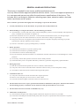
The following symbols found in this manual/instrument bear the respective descriptions as given.
Symbol
Description
Description
Type BF applied part
Date of manufacture
Attention, consult operator’s
manual
The CE Mark is a protected
conformity mark of European
Community. The products
herewith comply with the
requirements of the Medical
Device Directive 93/42/EEC.
Serial number
iv
Symbol
Service Manual JE-912AK
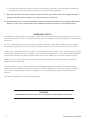
Precautions for Input Jack Use
NOTE
Do not perform EEG measurement without the Z, C3, C4, A1 and A2 electrodes.
Use of input jack Z
Connect the lead from the electrode (Z electrode) attached on the patient’s nasion to the input jack Z on the electrode
junction box. The purpose of this input jack is to eliminate AC interference positively.
NOTE
The input jack Z is also used for checking electrode impedance.
Use of input jacks C3 and C4
Connect the leads from the electrodes attached on the positions C3 and C4 to the input jacks C3 and C4 respectively.
NOTE
• The C3 and C4 electrodes are the reference electrodes for EEG measurement.
• The input jacks C3 and C4 must be attached for EEG measurement even when the C3 and C4 are not
programmed in any montage.
Use of input jacks A1 and A2, C3 and C4 during skin-electrode impedance check
When checking each electrode impedance, connect the leads from the electrode attached on the positions A1, A2, C3 and
C4 to the input jacks A1, A2, C3 and C4 respectively.
NOTE
• The A1 and A2 electrodes are the reference electrodes for skin-electrode impedance check.
• The input jacks A1 and A2 in addition to the Z, C3 and C4must be attached for the electrode
impedance check.
ECG AIRFLOW
X15
X19
Z
A1
X5
A2
C3
X6 PLM 1
X7 X16
C4
X8
O1
O2
X9 PLM 2
X10 X17
X1
X11
X2
X12
X3
X13 X18
X4
X14
CHEST
X20
ABDOMEN
X21
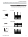
Checking electrode potentials for all active electrodes
Check the original electrode potential for all active electrodes by
programming a montage with the system reference electrode (Select
the 0 V button for reference electrode on the Montage dialog box).
Refer to “Programming Patterns” in Section 2 of the Operator’s
manual.
The digital EEG displays the EEG waveform in each channel by
subtracting two electrode potentials selected to a montage. The
subtracted result will be incorrect, if the electrode attachment is not
correct, the original electrode potential is flat or unstable, or artifact is
superimposed on the original electrode potential. Omit the
measurement result if the displayed EEG waveform is incorrect.
BODY POSITION
DC2
JE-914A Mini Junction Box
Service Manual JE-912AK
v
This page is intentionally left blank.
vi
Service Manual JE-912AK
Section 1 General
Introduction ........................................................................................................................ 1.1
Service Policy, Service Parts and Patient Safety Checks .................................................. 1.2
Service Policy .......................................................................................................... 1.2
Service Parts ........................................................................................................... 1.2
Patient Safety Checks ............................................................................................. 1.3
Maintenance Equipment/Tools ................................................................................. 1.3
General Information on Servicing ...................................................................................... 1.4
General Safety information ................................................................................................ 1.6
Specifications .................................................................................................................... 1.11
Panel Descriptions ........................................................................................................... 1.13
JE-912AK PSG Input Box ...................................................................................... 1.13
JE-914A Mini Junction Box .................................................................................... 1.15
Composition ..................................................................................................................... 1.16
Service Manual JE-912AK
1C.1
This page is intentionally left blank.
1C.2
Service Manual JE-912AK
1. GENERAL
Introduction
The JE-912AK PSG Input Box is an electrode junction box to measure
polysomnogram. The PSG input box communicates with an
electroencephalograph by USB communication. Up to 8 DC signals and SpO2 can
be measured.
This service manual provides useful information to qualified service personnel to
understand, troubleshoot, service, maintain and repair this JE-912AK PSG Input
Box.
All replaceable parts or units of this instrument and its optional units are clearly
listed with exploded illustrations to help you locate the parts quickly.
The “Maintenance” section in this service manual only describes the maintenance
that should be performed by qualified service personnel. The Maintenance section
in the operator’s manual describes the maintenance that can be performed by the
user.
The information in the operator’s manual is primarily for the user. However, it is
important for service personnel to thoroughly read the operator’s manual and
service manual before starting to troubleshoot, service, maintain or repair this
instrument. This is because service personnel need to understand the operation of
the instrument in order to effectively use the information in the service manual.
CAUTION
To turn the power off, follow the procedure in “Power Off Procedure”
in Section 3 of the EEG operator’s manual. Do not press the power
button on the PC unit. If the power button is pressed while a program
is running, the program, data file in the hard disk and/or MO disk may
be damaged.
Trademarks
Windows is a registered trademarks of Microsoft Corporation.
Service Manual JE-912AK
1.1
1. GENERAL
Service Policy, Service Parts and Patient Safety Checks
Service Policy
Our technical service policy for this PSG input box is to replace the faulty unit,
board or part or damaged mechanical part with a new one. Do not perform
electrical device or component level repair of the multilayer board or unit. We do
not support component level repair outside the factory for the following reasons:
• Most of the boards are multilayer boards with surface mount electrical
devices (SMD), so the mounting density of the board is too high.
• A special tool or high degree of repair skill is required to repair the multilayer
boards with SMDs.
Disassemble the PSG input box or replace a board or unit in an environment where
the PSG input box is protected against static electricity.
As background knowledge for repair, pay special attention to the following:
• You can reduce the repair time by considering the problem before starting repair.
• You can clarify the source of most of the troubles using the information from the
troubleshooting tables. Refer to “Troubleshooting“ of this manual.
Service Parts
Refer to “Replaceable Parts List” of this manual for the service parts for technical
service that we provide.
NOTE
When ordering parts or accessories from your Nihon Kohden
representative, please quote the NK code number and part name
which is listed in this service manual, and the name or model of the
unit in which the required part is located. This will help us to
promptly attend to your needs. Always use parts and accessories
recommended or supplied by Nihon Kohden Corporation to assure
maximum performance from your PSG input box.
1.2
Service Manual JE-912AK
1. GENERAL
Patient Safety Checks
Periodic maintenance procedures and diagnostic check procedures are provided in
this manual to ensure that the PSG input box is operating in accordance with its
design and production specifications. To verify that the PSG input box is working
in a safe manner with regard to patient safety, patient safety checks should be
performed on the PSG input box before it is first installed, periodically after
installation, and after any repair is made on the PSG input box.
For patient safety checks, perform the following checks as described in the
IEC60601-1 “Medical electrical equipment - Part 1: General requirements for
safety”:
• Protective earth resistance check
• Earth leakage current check
• Enclosure leakage current check
• Patient leakage current check
• Withstanding voltage check
Maintenance Equipment/
Tools
Test equipment
When repairing or calibrating the PSG input box, the following test equipment is
required.
• Oscillator: standard type
Checking tool
When checking the internal noise of the PSG input box and skin-electrode
impedance check function, the checking tools are necessary. Refer to Section 5
“Maintenance”.
Service Manual JE-912AK
1.3
1. GENERAL
General Information on Servicing
Note the following information when servicing the PSG input box.
CAUTION
Safety
There is the possibility that the outside surface of the PSG input box,
such as the operation keys, could be contaminated by contagious
germs, so disinfect and clean the PSG input box before servicing it.
When servicing the PSG input box, wear rubber gloves to protect
yourself from infection.
Liquid ingress
The PSG input box is not waterproof, so do not install the PSG input
box where water or liquid can get into or fall on the PSG input box. If
liquid accidentally gets into the PSG input box or the PSG input box
accidentally drops into liquid, disassemble the PSG input box, clean it
with clean water and dry it completely. After reassembling, verify that
there is nothing wrong with the patient safety checks and function/
performance checks. If there is something wrong with the PSG input
box, contact your Nihon Kohden representative to repair it.
Disinfection and cleaning
To disinfect the outside surface of the PSG input box, wipe it with a
non-abrasive cloth moistened with any of the disinfectants listed
below. Do not use any other disinfectants or ultraviolet rays to
disinfect the PSG input box.
- Chlorohexidine gluconate solution:
0.5%
- Benzethonium chloride solution:
0.2%
- Glutaraldehyde solution:
2.0%
- Benzalkonium chloride:
0.2%
- Hydrochloric alkyldiaminoethylglycine:
0.5%
Transport
• Use the specified shipment container and packing material to
transport the PSG input box. If necessary, double pack the PSG input
box. Also, put the PSG input box into the shipment container after
packing so that the buffer material does not get inside the PSG input
box.
1.4
Service Manual JE-912AK
1. GENERAL
Caution - continued
• When transporting the board or unit of the PSG input box, be sure to
use a conductive bag. Never put the it in an aluminum bag to
transport a bord or unit which a lithium battery is mounted. Never
wrap the board or unit of the PSG input box and mini junction box in
a styrene foam or plastic bag which generates static electricity.
Handling the PSG input box
• Because the outside surface of the PSG input box is made of resin,
the outside surface of the PSG input box is easily damaged. So when
handling the PSG input box, remove clutter from around the PSG
input box and be careful to not damage the PSG input box or get it
dirty.
• Because most of the boards in the PSG input box are multilayer
boards with surface mount electrical devices (SMD), a special tool is
required if remove and solder the elctrical devices on it. To avoid
damaging other electrical components, do not remove and solder
SMD components yourself.
Measuring and Test Equipment
Maintain the accuracy of the measuring and test equipment by
checking and calibrating it according to the check and calibration
procedures.
Service Manual JE-912AK
1.5
1. GENERAL
General Safety information
WARNING
• Never use this PSG input box in the presence of any flammable
anesthetic gas or high-concentration oxygen atmosphere. Failure to
follow this warning may cause explosion or fire.
• Never use this PSG input box in a high-pressure oxygen medical tank.
Failure to follow this warning may cause explosion or fire.
Using with an electrical surgical unit (ESU)
• Never use this PSG input box near an ESU. The PSG input box may
malfunction due to high-frequency noise from the ESU.
• When using this PSG input box with an ESU, refer to the instruction
manual for the ESU. Before measurement, check that the return plate
is correctly attached to the patient and that the PSG input box
operates correctly when using with the ESU. If the return plate is not
attached correctly, it may burn the patient’s skin where the electrodes
are attached.
• Before using the ESU, remove all needle electrodes and silver ball
electrodes from the patient. Failure to follow this warning may cause
burn on the patient.
MRI examination
• The PSG input box is not intended to be used during MRI.
• When performing MRI tests, remove all electrodes and transducers
from the patient which are connected to this PSG input box. Failure
to follow this warning may cause serious electrical burn on the patient
due to local heating caused by dielectric electromotive force. For
details, refer to the instruction manual for the MRI.
When performing defibrillation
• Before defibrillation, remove from the patient all electrodes and
transducers which are connected to connectors that do not have a
“
” or “
” mark. Otherwise, the discharged energy may cause
serious electrical burn or shock to the operator.
• Before defibrillation, remove all electrodes and transducers from the
patient which are connected from this PSG input box. If the
defibrillator paddle directly contacts these materials, the discharged
energy may cause serious electrical burn to the patient.
• Before defibrillation, all persons must keep clear of the bed and must
not touch the patient or any equipment connected to the patient.
Failure to follow this warning may cause serious electrical burn,
shock or other injury.
1.6
Service Manual JE-912AK
1. GENERAL
Installation
WARNING
Connect only the specified instruments to the connectors or socket
marked with
, by following the specified procedure. Otherwise,
electrical leakage current may harm the patient and operator.
CAUTION
When connecting the cables, make sure that each instrument is turned
off.
Electrode and Sensor
Attachment/Cable
Connection
WARNING
• Do not connect the Z electrode lead plug to a ground or equipotential
ground. Otherwise, leakage current from another instrument cause
electrical shock to the patient.
• When the JE-914A Mini Junction Box is not used, make sure that the
multiple connecter cover is firmly attached to the electrode junction
box. Failure to follow this warning may cause electrical shock to the
patient and operator.
• Before connecting or disconnecting the DC input cable to the DC input
connector, make sure that the power of the external instrument is
turned off or DC signal is not output from the external instrument.
Failure to follow this warning may cause electrical shock to the
patient and operator.
• Connect only the specified respiration sensor or pickup to the
AIRFLOW, CHEST and ABDOMEN connector by following the specified
procedure. Otherwise, electrical leakage current may harm the patient
and operator.
CAUTION
Before attaching a sensor, check whether it contains dry natural
rubber or not. Natural rubber may cause allergic reaction with
symptoms such as itching, redness, urticaria, swelling, fever, dyspnea,
symptoms similar to asthma, reduced blood pressure and shock. If
the patient shows any of the above symptoms, immediately stop using
the chest movement sensor and perform appropriate medical
treatment.
Service Manual JE-912AK
1.7
1. GENERAL
Operation
WARNING
• All activation testing must be applied under the supervision of the
physician in charge. Mouth gags, tongue depressors and gauze
sponges must always be prepared for use to prevent the patient from
biting his tongue or injuring himself during testing because any
pattern of flash stimuli may induce seizure activity.
When using the NE-224S Sub-dermal Straight Needle Electrode or
Intracranial Electrode
• Do not use the NE-224S sub-dermal straight needle electrode as a
measurement electrode for the EEG or evoked potential measurement
for any longer than one hour. When measuring the EEG or evoked
potential for over one hour, use the EEG disk electrode.
• Do not check the skin-electrode impedance when using a needle
electrode or intracranial electrode. Failure to follow this warning
injures the patient because these electrodes will be damaged by
electrolyzation inside the body.
SpO2 Measurement
WARNING
• SpO2 measurement may be incorrect in the following cases.
- When the carboxyhemoglobin (HbCO) or methemoglobin (metHb)
increases abnormally.
- When dye is injected in the blood.
- When using an electrosurgical unit.
- During CPR
- When measuring at a site where there are venous pulses.
- When there is body movement.
- When the pulse wave is small.
- When measuring the patient with peripheral circulation
insufficiency
• When the SpO2 probe is used on a neonate, low birth weight infant or
patient with a fever or peripheral circulation insufficiency, a slight
burn may result from the probe increasing the skin temperature at the
attached site by 2 or 3°C (4 or 5°F). Periodically check the attached
state of the probe and change the attachment site about every 8 hours.
• When performing MRI tests, remove the probes from the patient. The
local heat generated from the induced electromagnetic field may burn
the patient’s skin. For details, refer to the instruction manual for the
MRI.
1.8
Service Manual JE-912AK
1. GENERAL
CAUTION
• Always dry the connectors and do not let them contact liquid.
Otherwise, SpO2 measurement result may be incorrect.
• If the attachment site is dirty with blood, clean it before attaching the
probe. If there is nail polish on the attachment site, remove the
polish. Otherwise, the amount of transmitted light decreases and
measured data may be incorrect or measurement cannot be
performed.
• When measuring SpO2 under intense light (surgical light, bilirubin
lamp, sunlight), cover the probe with a blanket or cloth. Otherwise,
noise may interfere.
• Turn off the power of cellular telephones, small wireless devices and
other devices which produce strong electromagnetic interference
around a patient (except for PHS telephones allowed by the hospital
administrator). Otherwise, radio waves from devices such as cellular
telephones or small wireless devices may be mistaken as pulse waves
and the displayed data may be incorrect.
Cleaning or Disinfecting
CAUTION
Turn off the power before cleaning or disinfecting. Otherwise you may
get an electrical shock or the PSG input box may malfunction.
Maintenance
CAUTION
Do not disassemble the PSG input box when checking the PSG input
box or performing maintenance. If there is any damage or the PSG
input box is suspected to be faulty, attach an “Unusable” or “Repair
request” label to the system and contact your Nihon Kohden
distributor or representative.
Service Manual JE-912AK
1.9
1. GENERAL
WARNING
The programs contained in the system program installation CD-ROM
are protected by copyright law and international treaties.
Unauthorized reproduction or distribution of this software, or any
portion of it, may result in severe civil and criminal penalties, and will
be prosecuted to the maximum extent possible under law.
NOTE
• When the PSG input box is used in a high-frequency electric field, the
displayed waveform may be thicker.
• When the optional JL-951T3 SpO2 Adapter is connected to the PSG
input box and there is an extreme power surge, an “SpO2 UNSTABLE
PULSE” message appears. To prevent noise from the AC power line,
ground the electroencephalograph with a low impedance ground lead
(i.e. 1.5 m or less), connect the AC power cord to another AC outlet
and/or turn off the power of surrounding equipment.
• When the system program version of the EEG-1100A/J/K/G
Electroencephalograph is 03-01, 03-02 or 03-11, the PSG input box can
be connected. Upgrade the system program with the provided system
disk. Refer to “Upgrading the EEG System Program” in Section 2.
1.10
Service Manual JE-912AK
1. GENERAL
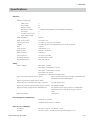
Specifications
Amplifier
Number of input jacks
EEG inputs:
Extra inputs:
Bipolar inputs:
Respiration inputs:
DC inputs:
Position sensor input:
SpO2 adaptor input:
Input impedance
Input circuit current
Internal noise level
CMRR
Gain
Low-cut filter
High-cut filter
Offset torelance
A/D conversion
Sampling and hold
Sampling frequency:
6
14
14
3 {RESP F (flow), RESP C (chest), RESP A (abdomen)}
8
1
1
100 MΩ
Less than 5 nA
Less than 1.5 µVp-p (0.53 to 60 Hz)
105 dB or greater at 60 Hz (bipolar input: 60 dB or greater)
×469.73
0.08 Hz (TC = 2 s)
120 Hz (-18 dB/oct)
±600 mV
16 bits (97 nV/LSB)
All electrodes at a time
100, 200, 500 Hz
Safety
Safety standard
IEC 60601-1 (1988)
IEC 60601-1 Amendment 1 (1991)
IEC 60601-1 Amendment 2 (1995)
IEC 60601-2-26 (1994)
EN 60601-1-1 (1992-06) with AMI (1995)
Type of protection against electric shock
Class I (when connecting to the EEG-1100/EEG-9100/
EEG-9200 electroencephalograph)
Degree of protection against electric shock
Electrode jacks, respiration jacks, SpO2 connector:
Type BF applied part
Degree of protection against harmful ingress of water Not protected (IPX0)
Degree of safety of application in flammable gas
Not suitable for use in the presence of a flammable
anaesthetic mixture with air or oxygen or nitrous
oxide
Mode of operation
Continuous
Electromagnetic Compatibility
IEC60601-1-2 (1993)
CISPR11(1990) Group1 CLASS B
Dimensions and Weight
JE-912AK:
JE-914A:
Service Manual JE-912AK
185 (W) × 72 (D) × 167 (H) mm, 1.0 kg
76 (W) × 25 (D) × 124 (H) mm, 0.2 kg (Cable length: 2.8 m)
1.11
1. GENERAL
1.12
Operation conditions
Temperature
Humidity
Atmospheric pressure
10 to 35° C (50 to 95° F)
30 to 80 % (non-condensing)
70 kPa to 106 kPa
Transport and Storage Conditions
Temperature
Humidity
Atmospheric pressure
-20 to 65° C (-4 to 149° F)
10 to 95 % (non-condensing)
70 kPa to 106 kPa
Service Manual JE-912AK
1. GENERAL
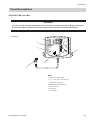
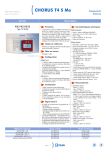
Panel Descriptions
JE-912AK PSG Input Box
WARNING
Connect only the specified instruments to the connectors or socket marked with , by following the
specified procedure. Otherwise, electrical leakage current may harm the patient and operator.
Front panel
1
Z
2
ECG
X15
A1
X5
O2
X10
A2
X6
X1
X11
C3
X7
X2
C4
X8
X3
X12 PLM1
X16
X13
O1
X9
X4
X14
2
5 10 20 50
PLM2
X17
X18
3
IMPEDANCE
CHECK
6
SpO2
DC1
4
5
Name
1. Impedance display LED
2. 2, 5, 10, 20 50 kΩ SELECTOR
(Impedance preset key)
3. IMPEDANCE CHECK key
4. SpO2 connector
5. USB cable
6. Cord hanger
Service Manual JE-912AK
1.13
1. GENERAL
Left side panel
1
DC 3
DC 4
Name
1. DC input connector
2. REMOTE MARK connector
DC 5
DC 6
DC 7
DC 8
DC 9
DC 10
REMOTE
MARK
2
Bottom panel
Multiple connecter
Connects to the JE-914A Mini Junction Box. To open the
multiple connecter cover, pry the cover off with a flat blade
screwdriver.
CAUTION
Only connect the JE-914A Mini Junction Box. When
another type of mini junction box is connected, the PSG
input box will malfunction.
1.14
Service Manual JE-912AK
1. GENERAL
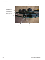
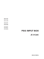
JE-914A Mini Junction Box
WARNING
Connect only the specified instruments to the connectors or socket, by following the specified
procedure. Otherwise, electrical leakage current may harm the patient and operator.
1
5
2
3
ECG AIRFLOW
X15
X19
Z
A1
X5
A2
C3
X6 PLM 1
X7 X16
C4
X8
O1
O2
X9 PLM 2
X10 X17
X1
X11
X2
X12
X3
X13 X18
X4
X14
6
CHEST
X20
ABDOMEN
X21
BODY POSITION
DC2
for JE-912A/912AK only
4
Attach the measurement
parameter name label here
NOTE
Name
1. Z jack
2. Electrode jack
3. Extra input jack
4. BODY POSITION connector
5. Bipolar derivation jack
6. Respiration pickup/sensor jack
Service Manual JE-912AK
Either of the following combinations cannot
be used.
- X19 jacks and AIRFLOW connector
- X20 jacks and CHEST connector
- X21 jacks and ABDOMEN connector
If either of the above combinations is used,
the signal from the X19, X20 or X21 jacks is
measured.
1.15
1. GENERAL
Composition
JE-912AK
UT-0727
PSG INPUT board
UT-0728
PSG AMP board
UT-0729
PSG MOTHER board
JE-914A
Mini junction box
UT-0730
1.16
PSG JUNCTION board
Service Manual JE-912AK
Section 2 Troubleshooting and
Error Messages
How to Troubleshoot ..........................................................................................................
Closing the Program and Shutting Down Windows .......................................
Troubleshooting .................................................................................................................
Waveform Acquisition ..............................................................................................
Control .....................................................................................................................
Error Messages .................................................................................................................
Acquisition Program ................................................................................................
SpO2 Measurement .................................................................................................
Service Manual JE-912AK
2.1
2.2
2.3
2.3
2.6
2.7
2.7
2.8
2C.1
This page is intentionally left blank.
2C.2
Service Manual JE-912AK
2. TROUBLESHOOTING AND ERROR MESSAGES
How to Troubleshoot
Use this section to locate, identify and solve a problem in the PSG input box or an
error message displayed on the screen. The troubleshooting tables in this section
are divided into general problems and displayed error messages.
1. Determine which troubleshooting table to use.
2. In the “Problem” or “Error Message” column, find the trouble item that
matches the problem or error message.
3. Do the action recommended in the “Action” column. (Do the first action
recommended in the “Action” column).
4. If the problem or error message is not solved, do the next action recommended
in the “Action” column. (If this does not solve the problem, do the next
recommended sections.)
5. If none of the actions solve the problem, contact your Nihon Kohden
distributor or representative.
WARNING
When checking a cable connection, close the EEG application
program, turn off the power of the electroencephalograph and all
connected external instruments, and unplug the AC power cord from
the AC outlet (For the procedure, refer to the next page). Failure to
follow this warning may cause electrical shock.
After checking the cable connection, turn on the power of all components, then
restart the PC unit.
Service Manual JE-912AK
2.1
2. TROUBLESHOOTING AND ERROR MESSAGES
Closing the Program and Shutting Down Windows
1. Open the Windows Task Manager.
When the mouse does not operate:
1) Press the Ctrl + Alt + Del key. The Windows Security dialog box
opens.
2) Select Task Manager to open the Windows Task Manager dialog box.
When the keyboard does not operate:
1) Right-click the task bar. The pop-up menu opens.
2) Select Task Manager to open the Windows Task Manager dialog box.
2. Select the program to close.
3. Select the End Task button.
4. Shut down Windows.
1) Select Shut Down from the Start menu. Or, press the Ctrl + Esc key,
then press the U key. The Shut Down Windows dialog box opens.
2) Select “Shut Down” in the “What do you want the computer to do ?”
list box.
3) Select the OK button. Windows shuts down and the PC unit power is
automatically turned off.
2.2
Service Manual JE-912AK
2. TROUBLESHOOTING AND ERROR MESSAGES
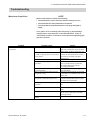
Troubleshooting
Waveform Acquisition
NOTE
Before measurement, confirm the following:
• The examination room is free from artifact-causing sources.
• The electrodes are firmly attached to the patient.
• The electrodes and electrode leads are not dirty, damaged or
frayed.
If not, pulse noise caused by static electricity or generated by a
display may be superimposed on the EEG waveform. Refer to
“Instrument Location” in Section 2 of each electroencepahalograph
operator’s manual.
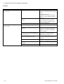
Problem
Noise or artifact is superimposed on the
waveforms.
Possible cause
The electrode lead is faulty.
One or more of the leads from the Z,
C3 and C4 input jacks are not attached
to the patient.
The bed is not grounded.
The electroencephalograph is not
grounded.
Several medical electronic instruments
are used together.
There is an AC outlet or table tap near
the patient or bed.
The PC unit or printer is placed near
the patient or electrode junction box.
A desk lamp or fluorescent light is
turned on.
The patient touched some metal part.
The patient is using an electric blanket.
There is a cellular phone near the
patient.
Service Manual JE-912AK
Action
Check the continuity of the electrode
lead with a multimeter. If the electrode
lead is faulty, replace it with a new one.
Attach these leads to the patient
because the Z electrode and C3 and C4
electrodes are necessary for EEG
measurement.
If the bed is metal, ground it.
If the AC outlet on the wall does not
have a ground terminal, ground the
electroencephalograph with the
provided ground lead.
Perform equipotential grounding for
each instrument.
Arrange the measurement environment
so that there is no influence from an AC
power line.
Arrange the measurement environment
so that unwanted radio frequency does
not affect the measurement.
Turn the desk lamp or fluorescent light
off.
Prevent the patient from touching metal
parts.
Turn the electric blanket off and unplug
the AC power cord, then use another
warming method.
Turn the cellular phone off.
2.3
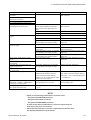
2. TROUBLESHOOTING AND ERROR MESSAGES
Problem
The waveform is not stable.
Possible cause
One or more of the leads from the Z,
C3 and C4 input jacks are not attached
to the patient.
New and old electrodes or different
types of electrodes are used together.
The waveform sometimes becomes flat.
The skin electrode contact impedance
of the C3 or C4 is high.
During waveform acquisition the
following message appears.
“The disk is full. Close the current file
to exit the acquisition program. Insert a
new disk.
[CAUTION]
Do not turn off the power of the main
unit or connected instruments (Photo
Drive unit or MO drive).
This can cause loss of EEG data and
damage to the hard disk.”
The waveform is not displayed.
The storage drive (the MO disk or hard
disk which saves the EEG data file) is
almost full.
The AC filter does not function.
Noise in AV derivation.
The electrode name on the screen is
indicated in red.
The color of the waveform and
background is the same.
The Display setting in the Pattern table
is set to "Off".
The AC filter setting is not correct.
Noise is not caused by AC line
influence.
An unused electrode for AV derivation
is selected in the AV Delete dialog box.
The electrode that is used for
measurement is not selected for the
storage electrode.
The electrode is selected for the AV
derivation but not selected for the
storage electrode.
The amplifier setting (sensitivity, time
constant or high-cut filter) does not
change with the Amp bar.
The Acquisition program does not
open.
The amplifier setting is not set to
"ACC".
--Faulty USB cable connection.
Faulty PSG input box.
2.4
Action
Attach these leads to the patient
because the Z electrode and C3 and C4
electrodes are necessary for EEG
measurement.
Do not use new and old electrodes or
different types of electrodes together.
This may cause high polarization
voltage.
Clean the electrode attachment to
reduce the impedance, and reattach the
electrode.
Click the OK button on the message
dialog box, then end the measurement
and save the file. Refer to "Starting and
Ending EEG Measurement - Ending the
Measurement and Saving the File" in
Section 5 of the EEG Operator’s
manual. After saving the file, prepare a
new MO disk, or delete unnecessary
files in the hard disk.
Use a different color for waveform and
background.
Set the Display setting to "On" for
necessary channels.
Select the correct AC filter setting (50
or 60 Hz) in the System program.
Use the proper filter according to the
artifact.
Delete unnecessary electrodes for AV
derivation in the AV Delete dialog box.
Select the electrode for the storage
electrode in the Electrodes to be Saved
dialog box of the System program.
Select all electrodes which are selected
for the AV derivation for the storage
electrode in the Electrodes to be Saved
dialog box of the System program.
Set the amplifier setting to ACC with
the pattern table in the System
program. You can temporarily change
the amplifier setting in the Acquisition
program and Review program.
When an error appears, follow the
instructions on the dialog box.
Turn off the power of the PC unit, then
check that the USB cable from the PSG
input box is correctly connected to the
PC unit.
Replace the PSG input box.
Service Manual JE-912AK
2. TROUBLESHOOTING AND ERROR MESSAGES
Problem
No calibration waveform appears on
the screen.
Artifact is superimposed on all
calibration waveforms.
Only baselines appear on the screen.
No waveform appears on the screen.
Artifact is superimposed on all signals
input from the electrode jacks.
A specific electrode signal does not
appear.
Artifact is superimposed on a specific
electrode signal.
No DC input signal appears on the
screen.
Artifact is superimposed on all DC
input signals.
A specific DC input signal does not
appear on the screen.
Artifact is superimposed on a specific
DC input signal.
SpO2 data is not displayed.
The respiration waveform input to the
AIRFLOW, CHEST or ABDOMEN
connectors is not displayed.
The signal input to any of the X15 to
X21 bipolar derivation jack
Possible cause
Faulty PSG MOTHER board.
Action
Replace the PSG MOTHER board or
PSG input box.
Faulty PSG MOTHER board if no
SELECTOR (Impedance threshold
display) LED on the PSG input box
lights.
Faulty PSG INPUT board.
Faulty PSG AMP board.
Faulty electrode lead.
Replace the PSG MOTHER board or
PSG input box.
Replace the PSG INPUT board.
Replace the PSG AMP board.
Replace the electrode lead.
Faulty PSG INPUT board.
Faulty PSG AMP board. An amplifier
corresponding to the signal is faulty.
Faulty electrode lead.
Replace the PSG INPUT board.
Replace the PSG AMP board or PSG
input box.
Replace the electrode lead.
Faulty electrode jack on the mini
junction box.
Faulty PSG INPUT board. An amplifier
corresponding to the signal is faulty.
Faulty PSG AMP board. An amplifier
corresponding to the signal is faulty.
Faulty PSG AMP board.
Replace the PSG JUNCTION board or
mini junction box.
Replace the PSG INPUT board or PSG
input box.
Replace the PSG AMP board or PSG
input box.
Replace the PSG AMP board or PSG
input box.
Faulty PSG AMP board. An amplifier
corresponding to the signal is faulty.
Replace the PSG AMP board.
The “On/Off” setting of the “DC01”
channel (SpO2 channel) in the DC
Input Conversion Display Setting
dialog box is set to “Off” (Pattern table
→ DC Conversion button).
A respiration pickup is connected to the
corresponding X19 to X21 jack.
Set the “On/Off” setting to “On”.
(DC Input Conversion Display Setting
dialog box → Set a Channel dialog box
→ On/Off area).
The reference electrode (G2) is not set
to “ 0 V”.
Set the reference electrode to “0 V”.
Remove the respiration pickup from the
corresponding jack*.
NOTE
• Either of the following combinations cannot be used.
- X19 jacks and AIRFLOW connector
- X20 jacks and CHEST connector
- X21 jacks and ABDOMEN connector
If either of the above combinations is used, the signal from the
X19, X20 or X21 jacks is measured.
• When the PSG input box is used in a high-frequency electric field,
the displayed waveform may be thicker.
Service Manual JE-912AK
2.5
2. TROUBLESHOOTING AND ERROR MESSAGES
Control
Problem
When the power is turned on, Windows
does not start.
Possible cause
Faulty PSG input box.
Problem with the Windows operating
system.
The EEG application program does not
work correctly.
Faulty PC unit.
A screen saver program is active.
Another windows application program
is active.
The two PSG input box are used and
the ID number of the second PSG input
box is not set to “2”.
The USB cable from the PSG input box
is not connected to the PC unit.
Faulty PSG input box.
Problem with the EEG application
program.
Faulty PC unit.
2.6
Action
1. Turn the power of the PC unit off.
2. Remove the USB cable from the PC
unit.
3. Restart the PC unit.
If Windows starts correctly, the PSG
input box is faulty. Replace the PSG
input box.
Reinstall the Windows operating
system and EEG system program.
Refer to the service manual of each
electroencephalograph.
Replace the PC unit.
Close the screen saver program.
Close all Windows application
programs. Or, delete the application
program if it conflicts with the EEG
system program.
Set the ID number of the second PSG
input box to “2” . Refer to “PSG
Mother Board” in Section 3.
Turn off the power of the PC unit, then
connect the USB cable to the PC unit
correctly.
Replace the PSG input box if an error
message for the PSG input box appears.
Reinstall the EEG system program.
Replace the PC unit.
Service Manual JE-912AK
2. TROUBLESHOOTING AND ERROR MESSAGES
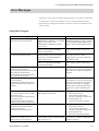
Error Messages
Following is a list of error messages during operation or the power on self check
for the PC unit. To solve the problem if an error message appears, find the
displayed error message from the table, then do the action recommended in the
Action column.
Acquisition Program
Error Message
The IMPEDANCE CHECK key on the
PSG input box has been pressed.
The SELECTOR key on the PSG input
box was pressed during startup.
<< USB 901 >> The electrode junction
box has been disconnected.
The Acquisition program will be closed
after saving the acquired data.
Please connect the electrode junction
box, and restart the program.
<< USB 902 >> No electrode junction
box was detected.
Confirm the electrode junction box is
connected and restart the Acquisition
program.
Possible Cause
When the power is turned on, the
IMPEDANCE CHECK key on the PSG
input box is pressed, or the
IMPEDANCE CHECK key makes a
short-circuit.
The connection between the PSG
INPUT board and PSG MOTHER
board is disconnected.
When the power is turned on, the
SELECTOR key on the PSG input box
is pressed, or the SELECTOR key
makes a short-circuit.
The connection between the PSG
INPUT board and PSG MOTHER
board is disconnected.
Faulty USB cable connection.
The PSG input box is not recognized.
<< USB 903 >> The electrode junction
box is disconnected or there is a data
transmission error.
After the Acquisition program closes,
turn off the power,
confirm the electrode junction box is
connected and restart the Acquisition.
<< USB 904 >> An overflow occurred
during data transmission from the
electrode junction box.
Restart the Acquisition program
Faulty data communication between the
PSG input box and PC unit.
The input boxes have save ID.
Disconnect one input box or set
different ID’s for each input box.
The two PSG input box are used and
the ID number of the second PSG input
box is not set to “2”.
Service Manual JE-912AK
Overflow occurs during data transfer.
Action
Do not press the IMPEDANCE
CHECK key when the power is turned
on. If the IMPEDANCE CHECK key is
faulty, replace the PSG INPUT board.
Check the cable connection. If the flat
cable is faulty, replace it with a new
one.
Do not press the SELECTOR key when
the power is turned on. If the
SELECTOR key is faulty, replace the
PSG INPUT board.
Check the cable connection. If the flat
cable is faulty, replace it with a new
one.
Check that the USB cable from the
PSG input box is correctly connected to
the PC unit, then open the Acquisition
program.
Check that the USB cable from the
PSG input box is correctly connected to
the PC unit, then open the Acquisition
program. If the same error message
appears again, reinstall the PSG input
box driver, or replace the PSG input
box.
1. Close the Acquisition program.
2. Turn the PC unit off.
3. Check that the USB cable is
correctly connected to the PC unit.
4. Restart the PC unit.
5. Open the Acquisition program.
1.
2.
3.
Close the Acquisition program.
Turn the PC unit off.
Check that the USB cable is
correctly connected to the PC unit.
4. Restart the PC unit.
5. Open the Acquisition program.
Set the ID number of the second PSG
input box to “2”. Refer to “PSG Mother
Board” in Section 3.
2.7
2. TROUBLESHOOTING AND ERROR MESSAGES
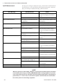
SpO2 Measurement
The SpO2 error message is displayed on SpO2 channel of the extended channel
bar and event bar. Solve the problem referring the following table. When the
SpO2 error message is displayed, the SpO2 value becomes 0 V.
Error Message
SpO2 UNSTABLE PULSE
Possible Causes
Patient body movement.
Action
Check the patient condition. Remove
the cause by changing the attachment
site, etc.
SpO2 CONNECTOR OFF
SpO2 CHECK PROBE
Probe attachment is unstable.
Firmly attach the probe to the patient.
SpO2 adaptor is disconnected from the
Firmly connect the SpO2 adaptor to the
PSG input box
PSG input box.
Faulty SpO2 adaptor
Replace the SpO2 adaptor.
Probe is detached from the patient.
Check the probe attachment condition.
Probe is disconnected from the SpO2
Firmly connect the probe to the SpO2.
adaptor.
SpO2 WEAK PULSE
Poor peripheral circulation
Check the patient condition. Remove
the cause by changing the attachment
site, etc.
Probe is attached too tight and prevents
Reattach the probe.
circulation.
SpO2 PULSE SEARCH
Searching for correct pulse waveform
Wait until the pulse waveform is
detected.
Pulse waveform is rough and SpO2
Check the probe attachment condition.
cannot be measured.
SpO2 NO PULSE
Probe is detached from the patient.
Reattach the probe.
Poor peripheral circulation
Check the patient condition. Remove
the cause by changing the attachment
site, etc.
Probe is attached too tight and prevents
Check the probe attachment condition.
circulation.
SpO2 CHECK PROBE SITE
Probe is detached from the patient.
Reattach the probe.
Probe attachment site is inappropriate.
Refer to the probe operator’s manual
and attach the probe on the appropriate
site.
SpO2 LIGHT INTERFERE
Probe is past the expiration date.
Replace the probe with a new one.
The measurement site is under surgical
Cover the probe with a blanket or cloth.
light, bilirubin light, sunlight, etc.
The AC filter setting is not correct
Check the AC filter setting in the
System Program.
SpO2 PROBE FAILURE
Faulty probe.
Replace the probe with a new one.
SpO2 hardware failure
Faulty SpO2 adaptor
Replace the SpO2 adaptor.
NOTE
When the optional JL-951T3 SpO2 Adapter is connected to the PSG input box and there
is an extreme power surge, an “SpO2 UNSTABLE PULSE” message appears. To prevent
noise from the AC power line, ground the electroencephalograph with a low impedance
ground lead (i.e. 1.5 m or less), connect the AC power cord to another AC outlet and/or
turn off the power of surrounding equipment.
2.8
Service Manual JE-912AK
Section 3 Board Description
General ..............................................................................................................................
Block Diagram .........................................................................................................
PSG INPUT Board and PSG AMP Board ..........................................................................
PSG MOTHER Board ........................................................................................................
Settings When Using Two PSG Input Boxes ......................................................................
Service Manual JE-912AK
3.1
3.1
3.2
3.6
3.8
3C.1
This page is intentionally left blank.
3C.2
Service Manual JE-912AK
3. BOARD DESCRIPTION
General
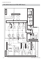
Block Diagram
JE-914A Mini Junction Box
PSG JUNCTION
board
JE-912AK PSG Input Box
PSG INPUT board
PSG MOTHER board
PSG AMP board
S/H
A/D converter
J-BOX
controller
USB
controller
To EEG
SH-Card
SpO2 probe
DC input (8 channel)
The PSG input box consists of the PSG INPUT board, PSG AMP board and PSG
MOTHER board. The JE-912AK PSG input box has 4 dual DC input connectors (8
channels). The general functions of the PSG input box are to:
• amplify the polysomnogram signals picked up from the electrodes, sensors SpO2
probe
• amplify the DC input signals from the DC input connectors.
• simultaneously sample the amplified signals at the frequency of 1 kHz,
• convert the sampled analog signals to digital serial data,
• output the digital data to the PC unit by USB communication
• measure the skin-electrode contact impedance and display the skin-electrode
contact impedance with the LEDs
Service Manual JE-912AK
3.1
3.2
-
From mini jnction box
Body position
FlLOW, CHEST, ABDOMEN
AGND
-
+
X19 (-) to X21(-)
X19 (+) to X21(+)
AGND
X15 (-) to X18 (-)
+
Z amplifier
X15 (+) to X18 (+)
Z
C4
C3
AGND
-
+
(×3 blocks for X19 to X21)
-
+
(×3 blocks for X15 to X18)
-
AGND
-
+
(×3 blocks for FlLOW, CHEST, ABDOMEN)
AGND
+
-
AGND
-
+
Voltge reference
K
A
A
K
+
Gain ×8
(×18 blocks for A1, A2, O1, O2, X1 to X14)
Impedance
check
A1, A2, O1, O2, X1 to X14
CNJ030
PSG INPUT board
AGND
AGND
120 Hz
-18 dB/oct
120 Hz
-18 dB/oct
120 Hz
-18 dB/oct
120 Hz
-18 dB/oct
Gain ×117
CNJ212
(Non-floating)
LEVEL
R-CHECK
K
A
RxD/TxD
+5 V
K
A
AGND
K
A
SpO2
From PSG MOTHER board
AGND
AGND
TC = 2 s
K
A
(Floating)
-
+
-
+
-
+
-
+
AGND
(Non-floating)
AGND
AGND
AGND
AGND
Sample and hold
MPX
-
+
MPX
INST
70 Hz
-18 dB/oct
120 Hz
-18 dB/oct
(×8 blocks)
MPX control
Impedance check
S/H
CN171
-
+
AGND
DC3 to DC10
From
PSG MOTHER board
PSG AMP board
3. BOARD DESCRIPTION
PSG INPUT Board and PSG AMP Board
Service Manual JE-912AK
3. BOARD DESCRIPTION
PSG INPUT board
Electrode potential signals from the JE-914A Mini Junction Box are processed
as follows. The top of each EEG amplifier circuit and respiration pickup/
bipolar deviation circuit has an input protection circuit to limit the input
voltage within ±9 V.
EEG Primary Amplifier Circuits
• 2 second time constant circuit
Provides a 2 second time constant.
• Primary operational amplifier (×8)
Amplifies the difference between the two input signals 8 times.
System Reference Voltage Generation Circuit
Averages the electrode potential between C3 and C4 and amplifies 1.14
times. This voltage is used for the system reference voltage for waveform
acquisition.
Z Signal Generation Circuit
Averages the electrode potential between C3 and C4. This voltage is fed
back to the Z electrode to reduce artifact.
Bipolar Derivation Primary Amplifier Circuit:
Primary operational amplifier
Amplifies the difference between pair of input signals for bipolar derivation 8
times.
Respiration Pickup Circuit/Airflow Sensor Input Circuit
• Primary operational amplifier
Respiration pick up circuit:
Amplifies the difference between pair of input signals for bipolar derivation 8
times.
Airflow sensor input circuit:
Buffers the signal from airflow sensor
• 2 second time constant circuit
Provides a 2 second time constant.
• Reset circuit
Resets the trace to the baseline.
• Secondary operational amplifier (×117)
Amplifies the signals 117 times.
• Anti-aliasing circuit (120 Hz, -18dB/Oct)
Filters any aliasing signal.
Service Manual JE-912AK
3.3
3. BOARD DESCRIPTION
Body Position Sensor Input Circuit
• Buffer amplifier
Provides 1.5 MΩ input impedance.
• Reset circuit
Resets the trace to the baseline.
• Attenuator
Attenuates the signals 1/4.
• Anti-aliasing circuit (120 Hz, -18dB/Oct)
Filters any aliasing signal.
PSG AMP board
EEG Secondary Amplifier Circuit/Bipolar Deviation Secondary
Amplifier Circuit
• 2 second time constant circuit
Provides a 2 second time constant.
• Reset circuit
Resets the trace to the baseline.
• Secondary operational amplifier (×117)
Amplifies the signals 117 times.
• Anti-aliasing circuit (120 Hz, -18dB/Oct)
Filters any aliasing signal.
Sample and Hold Circuit
Samples and holds signals at 1 kHz sampling frequency.
Impedance Check Indicator
• Impedance check LEDs
Shows the result of the electrode impedance check.
• Impedance threshold LEDs
Shows the skin-contact impedance check threshold.
DC Input Circuit
• Buffer amplifier
Provides 1.5 MΩ input impedance
• Reset circuit
Resets the trace to the baseline.
• Anti-aliasing circuit (70, 120 Hz, -18dB/Oct)
Filters any aliasing signal.
3.4
Service Manual JE-912AK
3. BOARD DESCRIPTION
• Sample and hold circuit (1 kHz)
Samples and holds signals at 1 kHz sampling frequency.
Multiplexing Circuit
Multiplexes the data from the sample and hold circuit and outputs it as serial
data.
Service Manual JE-912AK
3.5
3.6
To PSG INPUT
board (CN081)
USB cable
To PC unit
CN091
CN020
001
002
003
004
005
006
007
008
D+
D-
8.3 MHz
DGND
REMOTE MARK
DGND
+5 V
+3.3 V
LEVEL SW
IMPCHK SW
SpO2 - ON, SpO2 - DTC, RxD, TxD
12 MHz
USB Control
U041
IRQ2
IRQ
I/O port
SDRAM
SH-Bus
U091 CARD-E09A
+3.3 V
LED0 - LE9, SL0 - SL3
DGND
+5 V
CPU
SH7709A
1.8 V
Power
circuit
CN040
+5 V
JBOX Type
JBOX ID
IRQ1
DGND
2.048 MHz
DGND
Buffer
3.3 V <-> 5 V
U024
J-BOX
control circuit
U091
EPROM
DGND
+5 V
IMPCHK 50 K
IMPCHK START
INST
FRM
DATA
CLOCK
(Non-floating)
A/D converter
U074
AGND
+5 VF
U101
Impedance
check circuit
D/A converter
A/D, MPX,
Impedance check
control circuit
(Floating)
CN070
CN021
To PSG AMP board
AGND
+5 V
MJB - DTC
200/X500
AGND
+5 VF
DATA
SW A, SW B, SW C
S/H
MPX control
To PSG AMP board
CN050
3. BOARD DESCRIPTION
PSG MOTHER Board
Service Manual JE-912AK
3. BOARD DESCRIPTION
This board consists of the following components:
PSG Input Box Control Circuit
• Controls the overall operation of the PSG input box at 100 MHz clock
frequency using a SH7709A CPU (U091 CARD-E09A). The EPROM (256
kB×16 bit) contains the program to control the PSG input box operation.
• Simultaneously controls the reset circuits of all the amplifiers in the PSG
input box.
• Controls the impedance check function. The skin-electrode contact
impedance is calculated and the check result is displayed on the LEDs on the
PSG INPUT board and sent to the PC unit.
Power Supply Circuit
On the non-floating circuit
+5 V:
Power supply from the PC unit
+3.3V: Power supply for digital circuits
+1.8 V: Power supply for CARD-E09A
On the floating circuit
The following powers are generated by the DC-DC converter.
+5 VF: Power supply for floating circuits.
Isolation Circuits
The photocouplers are used for transferring the digital data from the floating
circuit to the non-floating circuit.
A/D Conversion Control Circuit/ Impedance Check Control Circuit
• A/D conversion control circuit
Convert the analog EEG signals, sensor signals and DC input signals into
digital signals. First, the analog signal is sampled and held. Second, the
sampled and held data is multiplexed. Third, the multiplexed data is
converted into digital EEG signals with a 16 bit A/D converter.
• Impedance check control circuit
The impedance check current is generated by an 8 bit D/A converter.
USB Communication Control Circuit
Controls the communication between the PSG input box and PC unit.
J012 Jumper Switch
This switch sets the ID number of the PSG input box.
Short: 1 (default setting)
Open: 2
Service Manual JE-912AK
3.7
3. BOARD DESCRIPTION
Settings When Using Two PSG Input Boxs
You can measure the polysomnogram for two patients simultaneously by using
two PSG input boxs. To use two PSG input boxes, do the following.
1. Set the ID number to “2” for the second PSG input box.
The ID number can be set by the J012 jumper switch on the PSG MOTHER
board in the PSG input box. The default setting is “1”. To change the
setting, refer to the service manual. When the power of the
electroencephalograph is turned on, the 10 kΩ or 20 kΩ impedance display
LED lights to indicate the ID number.
ID 1: 10 kΩ
ID 2: 20 kΩ
2. Create the shortcut icons for the first and second PSG input boxes. Refer to
“Settings When Using Two PSG Input Boxs” in Section 2 of the Operator’s
manual.
3.8
Service Manual JE-912AK
Section 4 Disassembly
Before You Begin ...............................................................................................................
Warnings, Cautions and Notes ................................................................................
Required Tools .........................................................................................................
Disassembly ......................................................................................................................
Service Manual JE-912AK
4.1
4.1
4.1
4.2
4C.1
This page is intentionally left blank.
4C.2
Service Manual JE-912AK
4. DISASSEMBLY
The procedures in this section tell how to remove, replace and install major
components in the PSG input box.
• To remove the connection cables, refer to “Cable Connections” in Section 2 of
the Operator’s manual.
Before You Begin
Warnings, Cautions and
Notes
Removing, replacing and installing major components should be done only by
qualified service personnel.
WARNING
• To avoid the possibility of injury to yourself or damage to the PSG
input box, do not install or remove any component or change
switch settings while the power is on.
• To avoid accidental discharge of static electricity which could
damage the components of the PSG input box, use a grounded wrist
strap when installing or removing any component of the PSG input
box.
• Before connecting or disconnecting a cable, close the EEG
application program, shut down Windows, turn off all components
and unplug the AC power cord from the AC outlet.
CAUTIONS
• Removal and replacement of any components in the PSG input box
should only be done by qualified service personnel.
• Use only parts recommended by Nihon Kohden to assure maximum
performance from your PSG input box.
Required Tools
Service Manual JE-912AK
•
•
•
•
•
Anti-static bench mat
Wrist ground strap
Phillips screwdriver (insulated type, for M3 and M4 screws)
Hex socket driver (for 8 mm floating bolt, 5.5 mm spacer bolt and nut)
Tweezers
4.1
4. DISASSEMBLY
Disassembly
1. Turn the PSG input box front side down.
2. Remove the four M4 binding head screws which fasten the rear cover to the
front cover.
3. Remove the rear cover.
4. Remove the five 8 mm floating bolts which fasten the PCB unit to the front
cover.
inside the shield
sheet (OUT)
PCB unit
inside the shield sheet (OUT)
4.2
Service Manual JE-912AK
4. DISASSEMBLY
5. Remove the PCB unit from the front cover.
6. Remove the five M3 screws with spring washers and open the shield sheet
(OUT).
7. Remove the flat cable and USB cable which are connected to the PSG
MOTHER board.
PSG MOTHER board
USB cable
Service Manual JE-912AK
Flat cable
4.3
4. DISASSEMBLY
The boards are connected with 5.5 mm spacer bolts and 5.5 mm spacer nuts.
PSG INPU board
PSG AMP board
Shield sheet (IN)
PSG MOTHER board
Spacer bolt
4.4
Spacer nut
Service Manual JE-912AK
Section 5 Maintenance
Checking the PSG Input Box .............................................................................................. 5.1
Checking Noise ......................................................................................................... 5.1
Checking the Skin-electrode Impedance Check Function ......................................... 5.2
Checking the EEG Input Circuit ................................................................................ 5.3
Checking the Amplifier .................................................................................... 5.3
Checking the Input Signal for Each Channel ................................................... 5.4
Service Manual JE-912AK
5C.1
This page is intentionally left blank.
5C.2
Service Manual JE-912AK
5. MAINTENANCE
Checking the PSG Input Box
Checking Noise
Use the EEG noise checker to check the internal noise of the PSG input box. This
checker shorts circuits all EEG inputs as shown in the circuit diagram. Assemble
the EEG noise checker locally with parts that are purchased locally or from your
Nihon Kohden distributor or representative.
1. Connect the EEG noise checker to the multiple connector of the PSG input
box.
2. Start the Acquisition program.
3. Set the EEG instrument to the following settings.
High-cut filter:
60 Hz
Time constant:
0.3 s
Sensitivity:
1 µV/mm
AC filter:
Off
Montage:
Any montage except E lead connection pattern.
Circuit diagram
4. Check that the amplitude of the noise on the screen is less than 1.5 mVp-p.
1
Required Parts
16
17
Description
24
Qty
Code No.
Connector PCR-S50FS
1
545287
Housing PCR-LS50LA
1
545394
25
Not used
26
27
Not used
28
Not used
29
30
33
Not used
34
Not used
35
Not used
36
37
42
43
44
Not used
50
To PSG input box
Noise checker
Service Manual JE-912AK
5.1
5. MAINTENANCE
Checking the Skinelectrode Impedance
Check Function
Use the EEG impedance checker to check the skin-electrode impedance check
function. This checker shorts circuits all EEG inputs as shown in the circuit
diagram. Assemble the EEG impedance checker locally with parts bought locally
or from your Nihon Kohden distributor or representative.
We recommend assembling the five different checkers to perform the impedance
check for the five different resistance values.
Checker 1 Checker 2 Checker 3 Checker 4 Checker 5
Resistor
2.0 kΩF
4.99 kΩF
10.0 kΩF
20.0 kΩF
49.9 kΩF
1. Connect the EEG impedance checker to the multiple connector of the PSG
input box.
2. Start the Acquisition program.
3. Do the skin-electrode impedance check with the 5 different checkers. Refer to
“Checking the Skin-electrode Impedance” in Section 5 of the EEG operator’s
manual.
Required Parts
Circuit diagram
1
Description
16
Qty
Code No.
Resistor MRS25F2001 2.0 kΩF
35
227051
Resistor MRS25F4991 4.99 kΩF
35
227434
Resistor MRS25F1002 10.0 kΩF
35
227728
Resistor MRS25F2002 20.0 kΩF
35
228014
Resistor MRS25F4992 49.9 kΩF
35
228398
Connector PCR-S50FS
1
545287
Housing PCR-LS50LA
1
545394
17
24
25
Not used
26
27
Not used
28
Not used
29
30
33
Not used
34
Not used
35
Not used
36
37
42
43
44
Not used
50
To PSG input box
5.2
Impedance checker
Service Manual JE-912AK
5. MAINTENANCE
Checking the EEG Input
Circuit
Checking the Amplifier
Use the EEG input checker to check amplifiers for each electrode on the EEG input
circuits on the PSG input box. This checker divides the applied signals to 1/
10000. (Example: 500 mV to 50 µV). Assemble the EEG input checker locally
with parts that are purchased locally or from your Nihon Kohden distributor or
representative.
1. Connect the EEG input checker to the multiple connector of the PSG input
box.
2. Start the Acquisition program.
3. Set the EEG instrument to the following settings.
High-cut filter:
120 Hz
Time constant:
0.3 s
Sensitivity:
10 µV/mm
AC filter:
Off
Montage:
(G-)
(G+)
Any electrode
0V
Circuit diagram
100 Ω
Ground (reference)
1
4
4. Apply 500 mV sine waves between pin 50 (500 mV)
and 1 (ground).
5. With the Voltage cursor, check that the amplitude of
each channel is 50 uV/mm.
(The amplitude of C3-0V, C4-0V is 0 V: flat)
5
6
7
16
Required Parts
17
18
19
Description
Qty
Code No.
Connector PCR-S50FS
1
545287
23
Housing PCR-LS50LA
1
545394
24
Resistor SN14C2CT26 1.00MΩ
1
070086
Resistor SN14C2CT26 100 Ω
1
066242
20
21
22
25
Not used
26
27
Not used
28
Not used
29
30
33
Not used
34
Not used
35
Not used
36
37
38
39
40
41
42
43
44
Not used
1 MΩ
49
50
To PSG input box
500 mV
Input checker
Service Manual JE-912AK
5.3
5. MAINTENANCE
Checking the Input Signal for Each Channel
You can check that applied input signals are correctly processed for each channel
with the JE-0005 EEG Pattern Checker and YZ-0243 JE-912A/AK Connection
Cable.
1. Connect the EEG pattern checker to the multiple connector of the PSG input
box with the JE-912AK connection cable (Code No.: 545634).
2. Start the Acquisition program.
3. Set the EEG instrument to the following settings.
High-cut filter:
Off
Time constant:
1 or 0.3 s
Sensitivity:
10 µV/mm
AC filter:
Off
Reference:
Off
Sweep speed:
10 s/page
Montage setting:
Set as shown left
4. Turn on the power of the EEG pattern checker and press the START button.
EEG pattern checker
ON/OFF switch
START button
5. Check the montage setting on the screen.
5.4
Service Manual JE-912AK
5. MAINTENANCE
The relationship between clock signal and electrode is as follows
Clock Signal No.
1
2
3
4
5
6
7
8
9
10
Electrode
A1
A2
C3
C4
O1
O2
X1
X2
X3
X4
Clock Signal No.
11
12
13
14
15
16
17
18
19
20
Electrode
X5
X6
X7
X8
X9
X10
X11
X12
X13
X14
Clock Signal No.
21
22
23
24
25
26
27
X15
X16
X17
X18
X19
X20
X21
Electrode
The negative or positive pulse signal appears according to the montage setting for
each channel. The montage of the following example is G1 (+): C3 and G2 (-): O2.
O2
1
5
10
15
20
25
30
C3
When the G2 (-) electrode is set to “0 V”, only the negative pulse according to the
selected electrode appears for the channel.
Service Manual JE-912AK
5.5
5. MAINTENANCE
This page is intentionally left blank.
5.6
Service Manual JE-912AK
Section 6 Replaceable Parts List
JE-912AK PSG Input Boxt ................................................................................................. 6.2
JE-914A Mini Junction Box ................................................................................................ 6.4
Service Manual JE-912AK
6C.1
This page is intentionally left blank.
6C.2
Service Manual JE-912AK
6. REPLACEABLE PARTS LIST
When ordering parts or accessories from your nearest Nihon Kohden Corporation
distributor, please quote the NK code number and part name which are listed in
this service manual, and the name or model of the unit in which the required part
is located. This will help us to promptly attend to your needs. Always use Nihon
Kohden parts and accessories to assure maximum performance from your
instrument.
Service Manual JE-912AK
6.1
6. REPLACEABLE PARTS LIST
JE-912AK PSG Input Box
Index
Code No.
1
2
3
4
5
6
7
8
9
10
11
12
13
14
15
16
6112-015677
6112-014286B
6132-013266B
6112-015499
6112-014259A
6114-056263A
6124-032421B
6114-11809B
6114-117447
6124-000668C
6114-000668C
127997
292015
6114-121585
596712
128069
1
1
1
1
1
5
1
1
1
1
1
8
4
1
3
1
Front cover
Rear cover
Front panel for JE-912AK
Shiled sheet (OUT)
Shiled sheet (IN)
Floating bolt
USB cable holder
Connector cover
Sponge
DC INPUT panel
Holder attachment
Spacer bolt (L9)
Spacer nut (L12)
LED spacer
Spacer (L7)
Spacer nut (L9)
A
B
C
UT-0727
UT-0728
UT-0729
1
1
1
PSG INPUT board
PSG AMP board for
PSG MOTHER board
d
531079
1
JE912AK USB cable
6.2
Q’ty
Description
Service Manual JE-912AK
6. REPLACEABLE PARTS LIST
11
2
10
4
15
13
7
9
C
6
16
14
1
B
D
6
3
A
5
8
Service Manual JE-912AK
12
6.3
6. REPLACEABLE PARTS LIST
JE-914 Mini Junction Box
Index
1
2
3
4
5
NK Code No.
6112-005072B
6143-01177
6113-041094A
6114-005612
273482
A
UT-0730
6.4
Qty
1
1
1
35
4
1
Description
Front panel
Rear cover assy
Strap
Electrode jack
Sensor jack
PSG JUNCTION board
Service Manual JE-912AK
Section 7 Connector Pin
Assignment
Input/Output Connector/Jack Pin Assignment .................................................................... 7.1
PSG Input Box .......................................................................................................... 7.1
SpO2 Connector .............................................................................................. 7.1
DC Input Connector ......................................................................................... 7.1
REMOTE MARK Connector ............................................................................ 7.1
Service Manual JE-912AK
7C.1
This page is intentionally left blank.
7C.2
Service Manual JE-912AK
7. CONNECTOR PIN ASSOGNMENT
Input/Output Connector/Jack Pin Assignment
WARNING
Connect only the specified instruments to the connectors or socket
marked with , by following the specified procedure. Otherwise,
electrical leakage current may harm the patient and operator.
PSG Input Box
SpO2 Connector
7
5
4
2
PIn No.
3
1
Unit side: TCS7678-01-201
Cable side: MP-371/7
Signal
1
DGND
2
Not used
3
+5 V OUT
4
RxD
5
TxD
6
Not used
7
CON CHK
DC Input Connector
Max, ±3 V, input impedance 1.5MΩ
1
PIn No.
Signal
3
1
2
2
Unit side: HSJ1462-01-010 (Code No.: 608389)
Cable side: 2.5 ϕ miniature jack, KP-2S (Code No: 608406)
7
3
DGND
DC INPUT
(channel 3, 5, 7, 9)
DC INPUT
(channel 4, 6, 8, 10)
REMOTE MARK Connector
6
2
3
4
PIn No.
Signal
1
Not used
2
MARK INPUT
3
DGND
5
1
Unit side: HSJ2000-01-010 (Code No.: 501503)
Cable side: 3.5 ϕ miniature jack (Code No: 606907)
Operator's Manual JE-912AK
4 to 7
Not used
7.1
5. CONNECTOR PIN ASSOGNMENT
Multiple Connector
WARNING
When the JE-914A Mini Junction Box is not used, make sure that the
multiple connector cover in firmly attached to the PSG input box.
Failure to follow this warning may cause electrical shock to the
patient and operator.
CAUTION
1
26
Only connect the JE-914A Mini Junction Box. When another type of
mini junction box is connected, the PSG input box malfunction.
PIn No.
25
Unit side:
Cable side:
7.2
Signal
Pin No.
Signal
1
X5
26
DC2 (BODY)
2
X6
27
MINI-DTC
3
X7
28
Not used
4
X8
29
X19
5
C3
30
X1
6
C4
31
X2
7
X9
32
X3
8
X10
33
X4
9
O1
34
X20
10
O2
35
X21
11
A1
36
Not used
12
A2
37
X19 + (FLW)
13
X11
38
X19 – (FLW)
14
X12
39
X20 + (CHT)
15
X13
40
X20 – (CHT)
16
X14
41
X21 – (ABD)
17
X15 + (ECG)
42
X21 – ( ABD)
18
X15 – (ECG)
43
Z
19
X16 + (PLM1)
44
X19_SEL
20
X16 – (PLM1)
45
X20_SEL
21
X17 + (PLM2)
46
X21_SEL
22
X17 – (PLM2)
47
Not used
23
X18 +
48
Not used
24
X18 –
49
Not used
25
AGND
50
Not used
50
PCR-E50LMD-SLB1
(Code No.: 513713)
Connector - PCR-S50FS
(Code No.: 545287)
Housing- PCR-LS50LA
(Code No.: 545394)
Operator's Manual JE-912AK