1
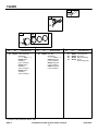
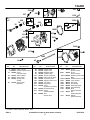
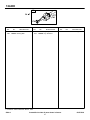
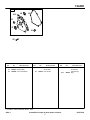
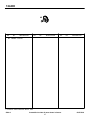
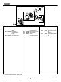
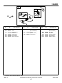
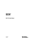
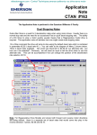
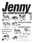
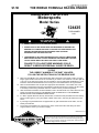
FORM MS–5226–3C–2/27/2003
FILE IN SECT. 2 OF SERVICE MANUAL
$1.50
THE WORLD FORMULA RACING ENGINE
Illustrated Parts List
Motorsports
Model Series
124435
TYPE NUMBER
8101.
WARNING:
MODEL 124435–8101–01 IS A RACING ENGINE
SPECIAL SKILLS AND KNOWLEDGE ARE REQUIRED TO PREPARE THE
ENGINES FOR COMPETITIVE USE. IF YOU ARE NOT FAMILIAR WITH THE
PROPER TECHNIQUES AND PROCEDURES, HAVE QUALIFIED
INDIVIDUALS DO THE WORK FOR YOU
THE ENGINES DO NOT HAVE GOVERNORS. ANY THROTTLE MECHANISM
MUST HAVE A RETURN–TO–IDLE SPRING SO THE ENGINE WILL RETURN
TO IDLE SPEED WHEN THE THROTTLE PEDAL IS RELEASED
FAILURE TO FOLLOW THESE WARNINGS COULD
RESULT IN SERIOUS PERSONAL INJURY OR DEATH
TO FIND
THE CORRECT NUMBER OF THE PART YOU NEED:
FOLLOW THE INSTRUCTIONS ON THE REVERSE SIDE
A.
B.
C.
D.
E.
F.
Refer to Engine Model, Type and Code Number that is stamped on the blower housing of engine.
Engine type numbers such as 0123 01 are listed only as 0123 in most instances. The two digits (01
or 02, etc.) to the right of the space may be required for more accurate parts identification in some
instances. Select the Illustrated Parts List covering the correct Model Series and Type Number.
Refer to the Illustrations and compare the original part with Illustration. The number next to the
illustration is the Reference Number. Assemblies include all parts shown in frames. All parts shown
in assembly frames having individual reference numbers can be purchased separately.
After the Reference Number has been identified, refer to the Numerical text, where Reference and
Primary Part Number are listed. THE PRIMARY PART IS USED ON ALL TYPE NUMBERS
EXCEPT THOSE TYPE NUMBERS UNDER “NOTE.”
If a “Note” appears below the Primary Part Number, it means that this part differs from the Primary
Part for certain types. If your Type number is listed under “Note,” order the part referred to at the
“Note.”
If your Engine Type Number does not appear after any part number listed under “Note,” use the
Primary Part Number.
For Engine Type Numbers not covered by this book, check other Parts Lists having the same
engine model or contact your source of supply.
PRINTED IN U.S.A.
COPYRIGHT by BRIGGS & STRATTON CORPORATION
All rights reserved. No part of this material may be reproduced or transmitted,
in any form or by any means, electronic or mechanical, including photocopying,
recording or by any information storage and retrieval system, without permission
in writing from Briggs & Stratton Corporation.
BEFORE OPERATING ENGINE
• Read entire Operating & Maintenance Instructions AND
the instructions for the equipment this engine powers.*
• Failure to follow instructions could result in serious injury
or death.
(
)
The safety alert symbol
is
used to identify safety information
about hazards that can result in personal injury.
A signal word (DANGER, WARNING,
or CAUTION) is used with the alert
symbol to indicate the likelihood and
the potential severity of injury. In addition, a hazard symbol may be used to
represent the type of hazard.
THESE INSTRUCTIONS CONTAIN SAFETY
INFORMATION TO
• Make you aware of hazards associated with engines
• Inform you of the risk of injury associated with those
hazards, and
• Tell you how to avoid or reduce the risk of injury.
HAZARD SYMBOLS
AND MEANINGS
Fire
Explosion
Toxic Fumes
• Start and run engine outdoors.
• Do not start or run engine in enclosed
area, even if doors or windows are
open.
Hot Surface
Moving Parts
WARNING
WARNING
Indicates a hazard which, if not
avoided, could result in
death or serious injury.
CAUTION
Indicates a hazard which, if not
avoided, might result in minor or moderate injury.
CAUTION, when used without the alert symbol, indicates
a situation that could result in
damage to the engine.
WARNING
The engine exhaust from this
product contains chemicals
known to the State of California
to cause cancer, birth defects, or
other reproductive harm.
Engines give off carbon monoxide, an
odorless, colorless, poison gas.
Breathing carbon monoxide can cause
nausea, fainting or death.
DANGER
Indicates a hazard which, if not
avoided, will result in death
or serious injury.
WARNING
Kickback
Shock
THE INTERNATIONAL
SYMBOLS USED ON THE
ENGINE OR IN THIS
MANUAL INCLUDE:
Safety Alert
Read Owner’s
Manual
Fuel
Fuel Shutoff
Oil
Choke
Stop
On Off
Rapid retraction of starter cord (kickback)
will pull hand and arm toward engine
faster than you can let go.
Broken bones, fractures, bruises or
sprains could result.
• When starting engine, pull cord
slowly until resistance is felt, then pull
rapidly.
• Remove all external equipment/enĆ
gine loads before starting engine.
• Direct coupled equipment compoĆ
nents such as, but not limited to,
blades, impellors, pulleys, sprockets,
etc., must be securely attached.
* Briggs & Stratton does not necessarily know what equipment this engine will power. For that reason, you should carefully
read and understand the operating instructions for the equipment on which your engine is placed.
WARNING
WARNING
Gasoline and its vapors are extremely
flammable and explosive.
Unintentional sparking can result in fire
or electric shock.
Fire or explosion can cause severe
burns or death.
Unintentional startĆup can result in
entanglement, traumatic amputation,
or laceration.
WHEN ADDING FUEL
• Turn engine OFF and let engine cool at
least 2 minutes before removing gas
cap.
• Fill fuel tank outdoors or in wellĆventiĆ
lated area.
• Do not overfill fuel tank. Fill tank to
approximately 1Ć1/2 inches below top
of neck to allow for fuel expansion.
• Keep gasoline away from sparks, open
flames, pilot lights, heat, and other
ignition sources.
• Check fuel lines, tank, cap, and fittings
frequently for cracks or leaks. Replace
if necessary.
WHEN STARTING ENGINE
• Make sure spark plug, muffler, fuel cap
and air cleaner are in place.
• Do not crank engine with spark plug
removed.
• If fuel spills, wait until it evaporates
before starting engine.
• If engine floods, set choke to OPEN/
RUN position, place throttle in FAST
and crank until engine starts.
WHEN OPERATING EQUIPMENT
• Do not tip engine or equipment at angle
which causes gasoline to spill.
• Do not choke carburetor to stop engine.
WHEN TRANSPORTING EQUIPĆ
MENT
• Transport with fuel tank EMPTY or with
fuel shutĆoff valve OFF.
WHEN STORING GASOLINE OR
EQUIPMENT WITH FUEL IN TANK
• Store away from furnaces, stoves,
water heaters or other appliances that
have pilot light or other ignition source
because they can ignite gasoline
vapors.
BEFORE PERFORMING REPAIRS
OR ADJUSTMENTS
• Disconnect spark plug wire and keep it
away from spark plug.
• Disconnect battery at negative terminal
(only engines with electric start).
WHEN TESTING FOR SPARK
• Use approved spark plug tester.
• Do not check for spark with spark plug
removed.
WARNING
Rotating parts can contact or entangle
hands, feet, hair, clothing, or accessoĆ
ries.
Traumatic amputation or severe laceraĆ
tion can result.
• Operate equipment with guards in
place.
• Keep hands and feet away from
rotating parts.
• Tie up long hair and remove jewelry.
• Do not wear looseĆfitting clothing,
dangling drawstrings or items that
could become caught.
WARNING
WARNING
Starting engine creates sparking.
Running engines produce heat. Engine
parts, especially muffler, become exĆ
tremely hot.
Severe thermal burns can occur on
contact.
Combustible debris, such as leaves,
grass, brush, etc. can catch fire.
• Allow muffler, engine cylinder and fins
to cool before touching.
• Remove accumulated combustibles
from muffler area and cylinder area.
• Install and maintain in working order a
spark arrester before using equipment
on forestĆcovered, grassĆcovered,
brushĆcovered unimproved land. The
state of California requires this (Section
4442 of the California Public ReĆ
sources Code). Other states may have
similar laws. Federal laws apply on
federal land.
Sparking can ignite nearby flammable
gases.
Explosion and fire could result.
• If there is natural or LP gas leakage in
area, do not start engine.
• Do not use pressurized starting fluids
because vapors are flammable.
WARNING
Replacement parts for fuel system (cap,
hoses, tanks, filters, etc.) must be the same
as original parts, otherwise fire can occur.
WARNING
DO NOT strike the flywheel with a hammer
or hard object because the flywheel may
later shatter during operation.
124400
306
307
1
2
3
REQUIRES SPECIAL TOOLS
TO INSTALL. SEE REPAIR
INSTRUCTION MANUAL.
718
REF.
NO.
1
2
PART
NO.
DESCRIPTION
REF.
NO.
555582 Cylinder Assembly
555140 Kit–Bushing/Seal
(Magneto Side)
3
15
306
Included in Engine Gasket Set–Ref No. 358.
∆ Included in Valve Gasket Set–Ref No. 1095.
5226–3
15
PART
NO.
1019 LABEL KIT
DESCRIPTION
555071 Seal–Oil
(Magneto Side)
555079 Plug–Oil Drain
557037 Shield–Cylinder
REF.
NO.
307
718
1019
PART
NO.
DESCRIPTION
555533 Screw
(Cylinder Shield)
555579 Pin–Locating
555577 Kit–Label
Included in Carburetor Overhaul Kit–Ref No. 121.
Assemblies include all parts shown in frames.
3
02/27/2003
124400
28
27
29
32
25
26
27
REF.
NO.
25
PART
NO.
REF.
NO.
DESCRIPTION
557001 Piston Assembly
(Standard)
––––––– Note –––––
557002 Piston
Assembly
(.010” Oversize)
557003 Piston
Assembly
(.020” Oversize)
557004 Piston
Assembly
(.030” Oversize)
Included in Engine Gasket Set–Ref No. 358.
∆ Included in Valve Gasket Set–Ref No. 1095.
5226–4
26
PART
NO.
DESCRIPTION
REF.
NO.
555514 Ring Set
(Standard)
––––––– Note –––––
555515 Ring Set
(.010” Oversize)
555516 Ring Set
(.020” Oversize)
555517 Ring Set
(.030” Oversize)
27
28
29
32
PART
NO.
555521
555520
557005
557078
DESCRIPTION
Lock–Piston Pin
Pin–Piston
Rod–Connecting
Screw
(Connecting Rod)
Included in Carburetor Overhaul Kit–Ref No. 121.
Assemblies include all parts shown in frames.
4
02/27/2003
124400
50
635
186
337
5
238
36
813
122
51
42
1130
42
238
1029
192
830
36
35
35
1022
33
34
1311
155
619
1034
1051
993
914A
1023
1174
914
7
1026
13
REF.
NO.
PART
NO.
45
REF.
NO.
DESCRIPTION
5
557011 Head–Cylinder
7 ∆555621 Gasket–Cylinder Head
13
555540 Screw
(Cylinder Head)
33
557018 Valve–Exhaust
34
557017 Valve–Intake
35
557024 Spring–Valve
(Intake)
36
557024 Spring–Valve
(Exhaust)
42
45
50
51
122
155
186
192
238
337
619
635
813
830
Included in Engine Gasket Set–Ref No. 358.
∆ Included in Valve Gasket Set–Ref No. 1095.
5226–5
1022
PART
NO.
557025
557038
557009
557044
557050
555547
557054
555548
557016
557039
555556
DESCRIPTION
Keeper–Valve
Tappet–Valve
Manifold–Intake
Gasket–Intake
Spacer–Carburetor
Plate–Cylinder Head
Connector–Hose
Adjuster–Rocker Arm
Cap–Valve
Plug–Spark
Screw
(Cylinder Head Plate)
555162 Boot–Spark Plug
557051 Clamp
(Intake Manifold)
555549 Stud
(Rocker Arm)
REF.
NO.
914
914A
993
1022
1023
1026
1029
1034
1051
1130
1174
1311
PART
NO.
DESCRIPTION
555535 Screw
(Rocker Cover)
555542 Screw
(Rocker Cover)
∆555554 Gasket–Cylinder Head
Plate
∆555523 Gasket–Rocker Cover
555528 Cover–Rocker
555531 Rod–Push
557015 Arm–Rocker
555555 Guide–Push Rod
557026 Ring–Retaining
557052 Stud
(Intake Manifold)
557013 Nut
(Intake Manifold)
557014 Washer
(Intake Manifold)
Included in Carburetor Overhaul Kit–Ref No. 121.
Assemblies include all parts shown in frames.
5
02/27/2003
124400
16
24
377
741
17A
REF.
NO.
16
17A
PART
NO.
DESCRIPTION
REF.
NO.
555620 Crankshaft
555573 Bearing–Ball
24
377
Included in Engine Gasket Set–Ref No. 358.
∆ Included in Valve Gasket Set–Ref No. 1095.
5226–6
PART
NO.
DESCRIPTION
555054 Key–Flywheel
555049 Key–Woodruff
REF.
NO.
741
PART
NO.
DESCRIPTION
555574 Gear–Timing
Included in Carburetor Overhaul Kit–Ref No. 121.
Assemblies include all parts shown in frames.
6
02/27/2003
124400
18
20
415
12
21
17
21
22
REF.
NO.
12
17
18
PART
NO.
DESCRIPTION
REF.
NO.
555525 Gasket–Crankcase
555527 Bearing–Ball
555559 Cover–Crankcase
20
21
PART
NO.
DESCRIPTION
REF.
NO.
555529 Seal–Oil
(PTO Side)
555037 Cap–Oil Fill
22
415
Included in Engine Gasket Set–Ref No. 358.
∆ Included in Valve Gasket Set–Ref No. 1095.
5226–7
PART
NO.
DESCRIPTION
557035 Screw
(Crankcase
Cover/Sump)
555563 Plug
Included in Carburetor Overhaul Kit–Ref No. 121.
Assemblies include all parts shown in frames.
7
02/27/2003
124400
46
REF.
NO.
46
PART
NO.
DESCRIPTION
REF.
NO.
DESCRIPTION
REF.
NO.
PART
NO.
DESCRIPTION
557041 Camshaft
Included in Engine Gasket Set–Ref No. 358.
∆ Included in Valve Gasket Set–Ref No. 1095.
5226–8
PART
NO.
Included in Carburetor Overhaul Kit–Ref No. 121.
Assemblies include all parts shown in frames.
8
02/27/2003
124400
125
1233
117
1250
1234
536
133
1317
151
94
883
975
137
98
629
436
254
1059
130
387
REF.
NO.
94
98
117
125
130
PART
NO.
DESCRIPTION
1218
REF.
NO.
557085 Kit–Idle Mixture
557084 Kit–Idle Speed
557012 Jet–Main
(Gasoline)
(Contains 7 Different
Sizes)
557006 Carburetor
557083 Valve–Throttle
133
137
151
254
387
436
536
629
883
Included in Engine Gasket Set–Ref No. 358.
∆ Included in Valve Gasket Set–Ref No. 1095.
5226–9
PART
NO.
DESCRIPTION
557080 Float–Carburetor
557082 Gasket–Float Bowl
557053 Stud
(Exhaust Manifold)
557079 Drain–Carburetor
Bowl
557033 Pump–Fuel
557045 Manifold–Exhaust
557043 Cleaner–Air
557087 Spring–Throttle
Return
557047 Gasket–Exhaust
REF.
NO.
975
1059
1218
1233
1234
1250
1317
PART
NO.
DESCRIPTION
557008 Bowl–Float
557046 Kit–Screw/Washer
557007 Seal–O Ring
(Carburetor)
557081 Jet–Needle
557088 Cap–Throttle Cable
557086 Tube–Emulsion
557014 Washer
(Exhaust Manifold)
Included in Carburetor Overhaul Kit–Ref No. 121.
Assemblies include all parts shown in frames.
9
02/27/2003
124400
564
564A
604
347
575
188
222
REF.
NO.
188
222
347
536
PART
NO.
DESCRIPTION
555538 Screw
(Control Bracket)
555618 Bracket–Control
555564 Switch–Rocker
557043 Cleaner–Air
REF.
NO.
564
564A
575
Included in Engine Gasket Set–Ref No. 358.
∆ Included in Valve Gasket Set–Ref No. 1095.
5226–10
PART
NO.
DESCRIPTION
555571 Screw
(Control Cover)
557049 Screw
(Control Cover)
557028 Switch–Starting
REF.
NO.
604
PART
NO.
DESCRIPTION
557048 Cover–Control
Included in Carburetor Overhaul Kit–Ref No. 121.
Assemblies include all parts shown in frames.
10
02/27/2003
124400
1312
1313
356
333
356A
1314
1304
334
1313A
577
920
813A
REF.
NO.
333
334
PART
NO.
DESCRIPTION
557040 Armature–Magneto
555539 Screw
(Magneto Armature)
REF.
NO.
PART
NO.
356
356A
577
813A
557031
557032
555373
555382
920
1304
1312
DESCRIPTION
Wire–Stop
Wire–Stop
Cable–Starter
Clamp
(Solenoid Mounting)
557067 Starter–Solenoid
557000 Limiter–Rev
557023 Clutch–Centrifugal
REF.
NO.
1313
1313A
1314
Included in Engine Gasket Set–Ref No. 358.
∆ Included in Valve Gasket Set–Ref No. 1095.
5226–11
PART
NO.
DESCRIPTION
557021 Gear–Clutch
(16 Teeth)(219Chain)
557020 Gear–Clutch
(17 Teeth)(219 Chain)
––––––– Note –––––
557091 Gear–Clutch
(18 Teeth)(219 Chain)
557092 Gear–Clutch
(19 Teeth)(219 Chain)
557019 Hardware–Mounting
(Centrifical Clutch)
Included in Carburetor Overhaul Kit–Ref No. 121.
Assemblies include all parts shown in frames.
11
02/27/2003
124400
363
23
1239
455
332
REF.
NO.
23
PART
NO.
DESCRIPTION
REF.
NO.
557030 Flywheel
332
363
Included in Engine Gasket Set–Ref No. 358.
∆ Included in Valve Gasket Set–Ref No. 1095.
5226–12
PART
NO.
DESCRIPTION
555038 Nut
(Flywheel)
19069 Puller–Flywheel
REF.
NO.
455
1239
PART
NO.
DESCRIPTION
555518 Cup–Flywheel
19433 Wrench–Flywheel
Included in Carburetor Overhaul Kit–Ref No. 121.
Assemblies include all parts shown in frames.
12
02/27/2003
124400
732
304
727
305A
305
REF.
NO.
304
PART
NO.
DESCRIPTION
REF.
NO.
557034 Housing–Blower
305
PART
NO.
DESCRIPTION
557036 Screw
(Blower Housing)
REF.
NO.
305A
727
732
Included in Engine Gasket Set–Ref No. 358.
∆ Included in Valve Gasket Set–Ref No. 1095.
5226–13
PART
NO.
DESCRIPTION
557042 Screw
(Blower Housing)
557065 Cover–Starter Drive
557064 Screw
(Starter Drive Cover)
Included in Carburetor Overhaul Kit–Ref No. 121.
Assemblies include all parts shown in frames.
13
02/27/2003
124400
608
597
456
689
459
1210
60
58
1211
65
REF.
NO.
55
58
60
PART
NO.
55
DESCRIPTION
REF.
NO.
557060 Housing–Rewind
Starter
557062 Rope–Starter
(Cut to Required
Length)
557063 Grip–Starter Rope
65
456
459
597
608
Included in Engine Gasket Set–Ref No. 358.
∆ Included in Valve Gasket Set–Ref No. 1095.
5226–14
PART
NO.
DESCRIPTION
557055 Screw
(Rewind Starter)
557058 Plate–Pawlm Friction
557059 Pawl–Ratchet
557061 Screw
(Pawl Friction Plate)
555576 Starter–Rewind
REF.
NO.
689
1210
1211
PART
NO.
DESCRIPTION
557057 Spring–Friction
557056 Pulley/Spring Assembly
(Pulley)
557056 Pulley/Spring Assembly
(Spring)
Included in Carburetor Overhaul Kit–Ref No. 121.
Assemblies include all parts shown in frames.
14
02/27/2003
124400
309
802
1090
510 783
1051
503
803
311
675
797
544
801
310
697
REF.
NO.
309
310
311
503
510
544
PART
NO.
DESCRIPTION
REF.
NO.
557068 Motor–Starter
557077 Screw
(Starter Motor)
497608 Brush Set
555376 Strap–Starter
557069 Drive–Starter
557075 Starter–Armature
675
697
783
Included in Engine Gasket Set–Ref No. 358.
∆ Included in Valve Gasket Set–Ref No. 1095.
5226–15
PART
NO.
DESCRIPTION
691261 Washer
(Brush Retainer)
557065 Screw
(Starter Motor)
557071 Gear–Pinion
REF.
NO.
797
801
802
803
1051
1090
PART
NO.
DESCRIPTION
555380 Nut
(Brush Retainer)
557076 Cap–Drive
557074 Cap–End
557072 Housing–Starter
557070 Ring–Retainer
557073 Retainer–Brush
Included in Carburetor Overhaul Kit–Ref No. 121.
Assemblies include all parts shown in frames.
15
02/27/2003
124400
358 ENGINE GASKET SET
3
883
993
12
7
51
20
1022
1095 VALVE GASKET SET
1022
51
7
993
121 CARBURETOR OVERHAUL KIT
51
REF.
NO.
PART
NO.
137
REF.
NO.
DESCRIPTION
555071 Seal–Oil
(Magneto Side)
7 ∆555621 Gasket–Cylinder Head
12 555525 Gasket–Crankcase
20 555529 Seal–Oil
(PTO Side)
51 ∆557044 Gasket–Intake
3
Included in Engine Gasket Set–Ref No. 358.
∆ Included in Valve Gasket Set–Ref No. 1095.
5226–16
121
137
358
883
PART
NO.
1218
DESCRIPTION
557089 Kit–Carburetor
Overhaul
557082 Gasket–Float Bowl
557090 Gasket Set–Engine
557047 Gasket–Exhaust
REF.
NO.
PART
NO.
DESCRIPTION
993 ∆555554 Gasket–Cylinder Head
Plate
1022 ∆555523 Gasket–Rocker Cover
1095
557027 Gasket Set–Valve
1218 D557007 Seal–O Ring
(Carburetor)
Included in Carburetor Overhaul Kit–Ref No. 121.
Assemblies include all parts shown in frames.
16
02/27/2003