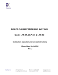
1
DYNAMP FLEXIBLE HIGH CURRENT PROBE
MODEL RR 30000-SD/24, 36, 48
SINGLE PHASE, CURRENT PROBE
Installation, Operation and Service Instructions
Manual Item No. 041143
Rev. H
DynAmp, LLC
3735 Gantz Road
Grove City, Ohio 43123 USA
Phone +1 614.871.6900
Fax +1 614.871.6910
www.dynamp.com
[email protected]
Installation, Operation and Service Manual
HIGH CURRENT PROBE
This Page is Intentionally Blank
© 2011 DynAmp, LLC
041143 H
Page ii
Installation, Operation and Service Manual
HIGH CURRENT PROBE
DynAmp, LLC WARRANTY
Items and components manufactured by Seller for permanent installation are warranted for
two (2) years from the date of shipment.
Items and components manufactured by Seller for portable and temporary use in more than
one location are warranted to be free from defects in material and workmanship for a period
of eighteen (18) months from the date of shipment.
Items and components not manufactured and resold by Seller are warranted by their
manufacturer.
Warranty repair shall be, at DynAmp’s option, in the form of repair or replacement of the
defective items or components. Concerning warranty repairs, DynAmp will be responsible
for DynAmp provided time, material and transportation costs (shipping or travel). Actual
method of warranty repair / correction will be determined by DynAmp at DynAmp’s sole
option. Such warranty repair shall constitute a fulfillment of all DynAmp, LLC liabilities in
respect to said items and components. In no event shall DynAmp, LLC be liable for
consequential damages.
Information in this document is subject to change without notice.
© 1996, 1997, 1999, 2005, 2008, 2011 DynAmp, LLC. All rights reserved.
Reproduction for purposes other than operation and service without written permission of
DynAmp, LLC is strictly forbidden.
This manual includes detailed drawings, installation, operation, service and maintenance.
Users should evaluate the information in the manual and their particular application.
DynAmp assumes no liability for any incidental, indirect, or consequential damages arising
fro the use of this documentation.
While all information presented is believed to be reliable and in accordance with accepted
engineering practices, DynAmp makes no warranties as to the completeness of the
information.
© 2011 DynAmp, LLC
041143 H
Page iii
Installation, Operation and Service Manual
HIGH CURRENT PROBE
This Page is Intentionally Blank
© 2011 DynAmp, LLC
041143 H
Page iv
Installation, Operation and Service Manual
HIGH CURRENT PROBE
Caution! Refer to manual before using product.
Model RR 30000-SD Current Probe conforms to the latest European directives and
standards concerning safety and electromagnetic compatibility.
European Low Voltage Directive 73/23/EEC and 93/68/EEC
European EMC Directive 89/336/EEC and 93/68/EEC
Safety Standards
EN 61010-1 Safety requirements for electrical equipment for measurement, control, and
laboratory use.
EMC Standards
RF Susceptibility:
EN 50082-1
3V/m Residential, Commercial, and Light Industrial Equipment.
RF Emissions:
EN 55011, Group 1, Class B
Industrial, Scientific, and Medical Equipment.
SAFETY
This product is designed to be safe under the following conditions:
•
Indoor use
•
Altitude up to 2000m
•
Maximum RH 80% for temperatures up to 31oC decreasing linearly to 40% RH at 85oC
Use of this product is limited to 600V ACRMS or DC between uninsulated conductor and
ground and for frequencies below 1kHz.
© 2011 DynAmp, LLC
041143 H
Page v
Installation, Operation and Service Manual
HIGH CURRENT PROBE
This Page is Intentionally Blank
© 2011 DynAmp, LLC
041143 H
Page vi
Installation, Operation and Service Manual
HIGH CURRENT PROBE
REVISION HISTORY
Page
Rev.
all
New
9,10
Revision Summary
Date
First Issue
03/96
A
Revise Specifications
10/96
all
B
Replace Transducer with Type RS5
11/96
Front
C
Warranty Statement
05/97
10
D
Revise Specifications
08/97
Front
D
Warranty Statement
08/97
ii, 1
E
Revise CE Statements
08/99
all
F
Update to DynAmp, LLC
06/05
all
G
ECO-3206: Update drawings to DynAmp logo
11/08
all
H
PAR 10245- Handling & Storage, New manual
format
03/11
© 2011 DynAmp, LLC
041143 H
Page vii
Installation, Operation and Service Manual
HIGH CURRENT PROBE
This Page is Intentionally Blank
© 2011 DynAmp, LLC
041143 H
Page viii
Installation, Operation and Service Manual
HIGH CURRENT PROBE
DynAmp, LLC Customer Support
For further assistance, contact DynAmp Customer Support at:
Americas:
Telephone: +1 614.871.6900
Fax: +1 614.871.6910
8:00 AM to 5:00 PM USA Eastern Time
From first Sunday in November to second Sunday in March – 13:00 GMT to 22:00 GMT
From second Sunday in March to first Sunday in November – 12:00 GMT to 21:00 GMT
Europe:
Telephone: +41 22.706.1446
Fax: +41 22.706.1311
8:30 AM to 5:00 PM Central European Time
From last Sunday in October to last Sunday in March – 7:30 GMT to 16:00 GMT
From last Sunday in March to last Sunday in October – 6:30 GMT to 15:00 GMT
After Hours Critical Service Emergency:
Telephone: +1 614.871.6906
5:00 PM to 8:00 AM USA Eastern Time
From first Sunday in November to second Sunday in March – 22:00 GMT to 13:00 GMT
From second Sunday in March to first Sunday in November – 21:00 GMT to 12:00 GMT
Central e-mail:
[email protected]
DynAmp web:
www.dynamp.com
© 2011 DynAmp, LLC
041143 H
Page ix
Installation, Operation and Service Manual
HIGH CURRENT PROBE
This Page is Intentionally Blank
© 2011 DynAmp, LLC
041143 H
Page x
Installation, Operation and Service Manual
HIGH CURRENT PROBE
TABLE OF CONTENTS
Par.
Title
Page
1. SAFETY _____________________________________________________________ 1
1.1 SAFETY SUMMARY .................................................................................................................1
1.2 SAFETY SYMBOLS ..................................................................................................................1
2. HANDLING AND STORAGE _____________________________________________ 3
3. SPECIFICATIONS _____________________________________________________ 5
4. DESCRIPTION ________________________________________________________ 7
4.1 OVERVIEW AND DESCRIPTION...............................................................................................7
4.2 AC CURRENT TRANSDUCER .................................................................................................8
4.3 EXTERNAL POWER SUPPLY ................................................................................................10
5. INSTALLATION ______________________________________________________ 11
5.1 INSTALLATION INSTRUCTIONS ...........................................................................................11
6. MAINTENANCE ______________________________________________________ 13
6.1 MAINTENANCE.......................................................................................................................13
6.2 BATTERY REPLACEMENT ....................................................................................................14
6.3 DYNAMP, LLC CUSTOMER SUPPORT.................................................................................15
LIST OF FIGURES
Figure 4.1
Figure 4.2
Figure 4.3
Figure 4.4
Figure 6.1
Figure 6.2
RR 30000-SD Current Probe Electronics Package ................................................. 7
Output Signal Cable and Adapter ............................................................................ 8
Type RS5 Flexible Transducer ................................................................................ 8
Input Power Connector .......................................................................................... 10
RR 30000-SD Current Probe ................................................................................. 13
Battery Replacement ............................................................................................. 14
LIST OF TABLES
Table 3.1 Model RR 30000-SD Specifications.......................................................................... 5
Table 3.1 Model RR 30000-SD Specifications (continued)....................................................... 6
LIST OF CHARTS
Chart 4.1 3kA Range Safe Operating Area............................................................................... 9
Chart 4.2 30kA Range Safe Operating Area............................................................................. 9
© 2011 DynAmp, LLC
041143 H
Page xi
Installation, Operation and Service Manual
HIGH CURRENT PROBE
This Page is Intentionally Blank
© 2011 DynAmp, LLC
041143 H
Page xii
Installation, Operation and Service Manual
HIGH CURRENT PROBE
1. SAFETY
1.1 SAFETY SUMMARY
The following general safety precautions must be observed during all phases of
operation, service, and repair of this instrument. Failure to comply with these
precautions or with specific WARNINGS given elsewhere in this manual violates safety
standards of design, manufacture, and intended use of the instrument.
The DynAmp, LLC. assumes no liability for the customer’s failure to comply with these
requirements.
! ! WARNING ! !
(Do not use until you have read this!)
Hazardous potentials may exist in the vicinity of the desired
current measurements. Use locally approved safety procedures
when working near these hazardous potentials.
It is
recommended not to install the DynAmp Flexible Current Probe
around a live bus that is at a hazardous potential. If installation is
not possible when the bus is inactive or turned off, always use
appropriate gloves and/or equipment that are approved when
working around hazardous potentials when installing the DynAmp
Flexible Current Probe in the vicinity of these hazardous
potentials.
The ac transducer and interconnection cable uses double insulation to protect the
operator from possible high-voltage potentials of the bus. The ac transducer and
interconnection cable are rated for Installation Category III, Pollution Degree 2. The
maximum voltage to earth rating for the transducer and cable is 600VAC. The electronics
package is not double insulated or protected against hazardous potentials from
connected instruments or mains adapters. Make sure the electronics package is well
away from the bus and that the inputs of instruments connected to the DynAmp Flexible
Current Probe outputs are not hazardous live.
1.2 SAFETY SYMBOLS
General definitions of safety symbols used on equipment or in manual.
General definitions of safety symbols used on equipment or in manual.
Direct current (power line).
Equipment protected by DOUBLE INSULATION or REINFORCED
INSULATION.
Caution (refer to accompanying documents).
© 2011 DynAmp, LLC
041143 H
Page 1
Installation, Operation and Service Manual
HIGH CURRENT PROBE
This Page is Intentionally Blank
© 2011 DynAmp, LLC
041143 H
Page 2
Installation, Operation and Service Manual
HIGH CURRENT PROBE
2. HANDLING AND STORAGE
DynAmp products are engineered and manufactured for use in industrial environments.
However, they contain sensitive electronic and mechanical components which may be
damaged and fail if not handled and stored properly. All products must be handled and
stored with the same care as any precision measurement instrument. Severe bumps or jolts
may damage internal parts and cause malfunction or premature failure. DynAmp products
are designed and assembled with conformal coating, shock mounting, and environmental
seals, when appropriate or when specified. However, this protection requires that the
product must be properly installed and operational before the protection is fully functional.
Therefore, adequate protection from humidity, shock, and temperature must be provided
during handling and storage prior to installation.
The handling and storage of equipment must be sufficient to meet the storage temperature
and humidity specifications of the product and to prevent any condensation or contact with
water or any other liquid. The storage location and container or crate must provide
adequate protection from precipitation (rain, snow, ice) and direct water contact. Adequate
shelter must be provided to prevent the accumulation of precipitation (rain, snow, ice) and
water which can lead to the deterioration or failure of shipping containers or crates and
cause water ingress. Storage in coastal or industrial areas subject to salt-laden or corrosive
air or areas of wind-driven sand or other abrasive dust must be adequate to prevent the
deterioration or failure of shipping containers or crates and cause ingress. Frequent
inspection of storage areas and storage containers or crates is required to ensure proper
storage conditions are being maintained.
If the shipping container or crate is opened and/or the equipment is removed for inspection
prior to installation, the equipment must be repackaged in the original undamaged container
or crate in the same manner as it was shipped to prevent environmental damage or placed
in a storage location that meets the required environmental and storage conditions.
General product storage temperature and humidity requirements:
Storage Temperature:
Storage Humidity:
-40 to 70°C
-40 to 158°F
85%, non-condensing
DynAmp, LLC does not assume liability for the customer’s failure to comply with handling
and storage requirements.
For further assistance, contact DynAmp customer support.
© 2011 DynAmp, LLC
041143 H
Page 3
Installation, Operation and Service Manual
HIGH CURRENT PROBE
This Page is Intentionally Blank
© 2011 DynAmp, LLC
041143 H
Page 4
Installation, Operation and Service Manual
HIGH CURRENT PROBE
3. SPECIFICATIONS
The specifications for the RR 30000-SD are given in table 3.1.
TABLE 3.1
MODEL RR 30000-SD SPECIFICATIONS
SIGNAL CONDITIONER
Input:
Type RS5 Transducer
Output:
3.0VAC or ±4.2VPK
Load >500 ohm
Output Connector:
BNC female
Switchable Scaling:
3kA/30kA @ 1mV/0.1mV per amp
Accuracy:
±1.0% of full scale
Linearity:
±0.2% of reading 10%...100% of full scale
Repeatability:
±0.1% of reading 10%...100% of full scale
Frequency Response:
8Hz to 100kHz (-3dB points)
Phase error:
<±0.5 maximum 50-60 Hz
Noise:
<10.0mV ac maximum
DC offset:
<5.0mV dc maximum
Temperature range:
Operational
-20ºC to 85ºC (-4ºF to 185ºF
Gain Change ±0.08%/ºC maximum
DC offset
±0.3mV/ºC maximum)
+3.0VDC/100mA from (2) 1.5V “AA” alkaline cells
or by mini power connector (2.1mm) on end of enclosure
Battery life (full scale input current @ 60 Hz) 25...30 Hrs.
Switch (Range and Power) LED Flashes once per 3 seconds if
the Current Probe is on and the battery voltage is good.
3kA/OFF/30kA
Power:
Controls:
Material:
ABS Plastic
Dimensions:
1.0H x 2.4W x 3.8D inches
(25.4H x 71.0W x 96.5D) mm
Weight:
0.1 lbs. (0.045 kg)
© 2011 DynAmp, LLC
041143 H
Page 5
Installation, Operation and Service Manual
HIGH CURRENT PROBE
TABLE 3.1
MODEL RR 30000-SD SPECIFICATIONS (CONTINUED)
TRANSDUCER
Transducer Jacket
TPE rubber; double insulated; flame retardant
UL 94 V-0 rated
Output Cable Jacket:
FEP Teflon; brown color
Couplings:
Polypropylene; flame retardant UL 94 V-0 rated; black color
Transducer Cover:
Silicone impregnated fiberglass; silver gray color
Minimum Bending
Radius:
Cable OD
1.5 in. (38.1 mm)
Coupling O.D.
0.875 in. (22.20 mm)
Connecting Cable:
Length 78.7 in. (2.0m) shielded
Temperature:
Operational -20ºC to100ºC (-4ºF to 212ºF)
Position Sensitivity:
<±2.0% with measured bus > 1” from head
External Magnetic Field:
<±1.0% with external bus > 8” from head
0.625 in. (15.87 mm)
Dimensions:
...SD/24
Length (Open)
I.D. (Closed)
O.D. (Closed)
Weight
24 in. (610 mm)
8.3 in. (209.9 mm)
7.0 in. (178.2 mm)
0.4 lbs. (0.18 kg)
...SD/36
Length (Open)
I.D. (Closed)
O.D. (Closed)
Weight
36 in. (915 mm)
12.0 in. (305 mm)
10.9 in. (277 mm)
0.6 lbs. (0.27 kg)
...SD/48
Length (Open)
I.D. (Closed)
O.D. (Closed)
Weight
48 in. (1220 mm)
15.9 in. (404 mm)
14.7 in. (372.2 mm)
0.8 lbs. (0.36 kg)
Safety Rating:
Double Insulated Installation Category III,
Pollution Degree 2, 600VAC to Earth
Working Voltage:
600VAC to Earth
Head/Cable Test:
5550VAC for 1 minute surface to output
ACCESSORIES:
Standard:
Output Cable: BNC Male to BNC Male 12 in. (304.8 mm)
Adapter: BNC Female to Dual Banana Plug
© 2011 DynAmp, LLC
041143 H
Page 6
Installation, Operation and Service Manual
HIGH CURRENT PROBE
4. DESCRIPTION
4.1 OVERVIEW AND DESCRIPTION
The DynAmp Flexible High Current Probe Model RR 30000-SD is an assembly similar in
purpose to a CT or current transformer. It may be used to measure ac currents from as low
as several amps to a maximum of 30.0kA rms. The device output is an analog voltage that
is proportional to the current in the conductor. The output signal is isolated from the
hazardous conductor potential and is an exact replica of the ac current waveform in the
conductor. The output signal is available via a BNC connector and is quite easily connected
to many different measurement devices. Output adapters have been included with the RR
30000-SD for your convenience. These adapters allow quick connection to an oscilloscope
via a BNC connector or the voltage terminals of a multimeter via banana plugs.
The RR 30000-SD comes standard with two ranges selectable by the switch mounted on
the electronics package. The ranges are 3kA and 30kA yielding respectively 3kA and 30kA
rms ac as the maximum current that can be measured. When the RR 30000-SD is turned
on, the LED mounted behind the translucent ruby panel on the package end slowly blinks to
indicate the unit is on and the battery voltage is sufficient to function properly on all ranges.
This LED indication is characterized by blinking approximately once every three seconds. If
no light is observed, the batteries of the RR 30000-SD should be replaced.
The RR 30000-SD comes equipped with an external mini jack located on the package. This
is for those wanting to supply power to the RR 30000-SD for a longer period than the
internal battery life will allow. External dc adapters are available for this purpose but are
sold as an option. The power required is +3.0VDC /100mA. Any external dc power supply
adapter must be safety rated.
Figure 4.1
RR 30000-SD Current Probe Electronics Package
© 2011 DynAmp, LLC
041143 H
Page 7
Installation, Operation and Service Manual
HIGH CURRENT PROBE
Figure 4.2
Output Signal Cable and Adapter
4.2 AC CURRENT TRANSDUCER
The RR 30000-SD design utilizes the lightweight and flexibility of the AC Current
Transducer. This transducer is a versatile current probe that may be wrapped around most
conductors. Three standard lengths are available. They are 24, 36, and 48 inches. It's
application versatility and high-voltage isolation rating clearly distinguishes the RR 30000SD from other current measuring methods. The measuring transducer is constructed from
non-ferrous materials, minimizing any circuit loading.
The frequency response of the RR 30000-SD is wide compared to conventional CTs. This
allows the user to monitor a much wider range of line harmonic components than
conventional CTs allow. The RR 30000-SD was designed to be very flexible, larger in
aperture and smaller in cross section than many conventional CTs. This allows
measurement in tight places as never before possible.
Figure 4.3
Type RS5 Flexible Transducer
© 2011 DynAmp, LLC
041143 H
Page 8
Installation, Operation and Service Manual
HIGH CURRENT PROBE
The output voltage of the transducer is proportional to the product of the current and the
frequency. At higher frequencies, the output voltage of the transducer may damage the
input circuits of the electronics package. Refer to Chart 4.1 and Chart 4.2 for the safe
operating areas of the 3kA and the 30kA range respectively.
3000A Range
3500
19.2 kHz
Current (A)
3000
2500
2000
1500
1000
500
0
0.01
577 Amps
0.10
1.00
10.00
100.00
F requency (kHz)
Chart 4.1
3kA Range Safe Operating Area
30kA Range
35
2.8 kHz
30
25
Current (kA)
20
15
8.5kA
10
5
0
0.01
850 Amps
0.1
1
10
100
F requency (kHz)
Chart 4.2
30kA Range Safe Operating Area
© 2011 DynAmp, LLC
041143 H
Page 9
Installation, Operation and Service Manual
HIGH CURRENT PROBE
4.3 EXTERNAL POWER SUPPLY
The user may choose to purchase a suitable external power supply. Figure 4.4 shows the
important dimensions of the power connector and the required polarity of the supply voltage.
The external power supply should have the CE mark and must be rated for +3.0VDC/340mA.
Figure 4.4
Input Power Connector
© 2011 DynAmp, LLC
041143 H
Page 10
Installation, Operation and Service Manual
HIGH CURRENT PROBE
5. INSTALLATION
5.1 INSTALLATION INSTRUCTIONS
The RR 30000-SD was made to allow the operator to connect this measurement device
around a conductor without disconnecting the conductor, as many CTs presently demand.
Even though the Flexible Transducer output is ac, there are instances where the user will
want to orient the transducer so that proper polarity will exist at the output terminals. This is
done by installing the transducer around the conductor with the molded-in arrow on the latch
(see Figure 4.3) pointing in the direction of conventional current flow. Conventional current
flow is defined as current flowing from the positive to the negative potential.
The Flexible Transducer must be installed with the interconnection cable on the outside of
the loop when the latch is engaged. The polarity arrow, the double insulation, and the
warning symbols will all be on the outside of the loop. It should also be noted that the
current probe will produce twice the output voltage if you wrap the transducer around the
conductor twice.
There is minimal shock hazard using the RR 30000-SD, as the transducer does not
generate high voltages at low frequencies. Each transducer has been Hi-Pot tested to
several thousand volts with no voltage breakdown. This particular characteristic allows
high-current measurement (with a wide frequency bandwidth) of conductors at less than
600VAC potential to earth.
! ! WARNING ! !
(Do not use until you have read this!)
Hazardous potentials may exist in the vicinity of the
desired current measurements. Use locally approved
safety procedures when working near these hazardous
potentials. It is recommended not to install the DynAmp
Flexible High Current Probe around a live bus that is at a
hazardous potential. If installation is not possible when
the bus is inactive or turned off, always use appropriate
gloves and/or equipment that are approved when working
around hazardous potentials when installing the DynAmp
Flexible High Current Probe in the vicinity of these
hazardous potentials.
Do not exceed the minimum bending radius of the AC Current Transducer when installing
the transducer around the conductor. Exceeding the bending radius will degrade the
measurement accuracy.
Make sure the AC Current Transducer and its output cable are clean before installing them
around the conductor. If the transducer and cable are not clean, the contaminants on them
may provide a conductive path for a high-voltage breakdown. Also, check the transducer
and output cable for cuts and abrasions. Do not use the transducer if damaged.
© 2011 DynAmp, LLC
041143 H
Page 11
Installation, Operation and Service Manual
HIGH CURRENT PROBE
This Page is Intentionally Blank
© 2011 DynAmp, LLC
041143 H
Page 12
Installation, Operation and Service Manual
HIGH CURRENT PROBE
6. MAINTENANCE
6.1 MAINTENANCE
Preventive maintenance primarily consists of cleaning the transducers and cables to prevent
surface contamination. Use a mild detergent and a damp cloth to clean the transducers and
cables. Remove the detergent with a damp cloth, then wipe with a clean, dry cloth.
NOTE
The use of solvents as cleaners is not recommended unless thoroughly tested
and found harmless to all surfaces and parts. Do not submerse current probe
into water or other fluids.
3Vdc/100mA
INPUT
MODEL
3Vac (MAX)
OUTPUT
RR 30000-SD/24
ITEM #
041322
OUTPUT
3.0 VRMS
SCALING
1V=1kA/10kA
(MAX)
SERIAL #
DynAmp, LLC.
(U.S.A.)
Figure 6.1
RR 30000-SD Current Probe
© 2011 DynAmp, LLC
041143 H
Page 13
Installation, Operation and Service Manual
HIGH CURRENT PROBE
6.2 BATTERY REPLACEMENT
SAFETY WARNING
Before removing the battery cover, make sure that
the Transducer is removed from around
any active conductor.
The battery compartment may be accessed by pressing down on the arrow molded into the
battery compartment cover to release the latch, then sliding the cover off. Remove the old
batteries and install the new batteries in the position as shown in Figure 6.2. Slide the cover
onto the enclosure until the latch engages. The batteries used in the RR 30000-SD Current
Probe are type “AA” alkaline cells or equivalent. Replacement with other than the specified
battery will invalidate the warranty.
3Vdc/100mA
INPUT
3Vac (MAX)
OUTPUT
MODEL
RR 30000-SD/24
ITEM #
041322
OUTPUT
3.0 VRMS
SCALING
1V=1kA/10kA
(MAX)
SERIAL #
DynAmp, LLC.
(U.S.A.)
Figure 6.2
Battery Replacement
© 2011 DynAmp, LLC
041143 H
Page 14
Installation, Operation and Service Manual
HIGH CURRENT PROBE
6.3 DYNAMP, LLC CUSTOMER SUPPORT
For further assistance, contact DynAmp Customer Support at:
Americas:
Telephone: +1 614.871.6900
Fax: +1 614.871.6910
8:00 AM to 5:00 PM USA Eastern Time
From first Sunday in November to second Sunday in March – 13:00 GMT to 22:00
GMT
From second Sunday in March to first Sunday in November – 12:00 GMT to 21:00
GMT
Europe:
Telephone: +41 22.706.1446
Fax: +41 22.706.1311
8:30 AM to 5:00 PM Central European Time
From last Sunday in October to last Sunday in March – 7:30 GMT to 16:00 GMT
From last Sunday in March to last Sunday in October – 6:30 GMT to 15:00 GMT
After Hours Critical Service Emergency:
Telephone: +1 614.871.6906
5:00 PM to 8:00 AM USA Eastern Time
From first Sunday in November to second Sunday in March – 22:00 GMT to 13:00
GMT
From second Sunday in March to first Sunday in November – 21:00 GMT to 12:00
GMT
Central e-mail:
[email protected]
DynAmp web:
www.dynamp.com
© 2011 DynAmp, LLC
041143 H
Page 15