1
TITLE PAGE
INFORMATION MANUAL
EXTRA 300L
MANUFACTURER
EXTRA Flugzeugproduktions- und Vertriebs- GmbH
Flugplatz Dinslaken
46569 Hünxe, Federal Republic of Germany
WARNING
This is an Information Manual and may be used for general purposes only.
This Information Manual is not kept current.
It must not be used as a substitute for the official FAA/EASA Approved Pilot's Operating
Handbook required for operation of the airplane.
Left blank intentionally
Pilot´s Operating Handbook
EXTRA 300L
LOG OF REVISIONS
Dates of issue for original and revised pages:
Date and sign of approval:
Original ......................... 9. September 1994
LBA approved ................... 31. January 1995
Revision No. 1 ....................... 26. June 1997
LBA approved .................... 27. August 1997
Revision No. 2 ......................... 7. June 1999
LBA approved ........................ 23. June 1999
Edition No. 2 ......................... 20. April 2002
LBA approved ................... 30. October 2002
Rev. No. 1, 2nd Ed. ...... 15. December 2005
EASA Approval N° ......... EASA.A.A.01101
Date of Approval ........... 20. December 2005
Rev. No. 2, 2nd Ed. ..... 20. September 2006
EASA Approval N° ......... EASA.A.A.01319
Date of Approval ............ 20. November 2006
Rev. No. 3, 2nd Ed. ................. 6. June 2008
EASA Approval N° ......... EASA.A.C.08351
Date of Approval ..................... 24. July 2008
Rev. No. 4, 2nd Ed. ........ 5. December 2008
EASA Approval N° ......... EASA.A.C.10781
Date of Approval ............. 18. February 2009
Rev. No. 5, 2nd Ed. ............ 16. March 2009
Approved under the authority of DOA
N° EASA.21J.073 (ECO: ÄM-300-09-07)
Date of Approval ...................... 6. April 2009
Rev. No. 6, 2nd Ed. ............ 31. March 2009
EASA Approval N° ..................... 10026766
Date of Approval .................. 7. August 2009
Rev. No. 7, 2nd Ed. .......... 08. October 2009
Approved under the authority of DOA
N° EASA.21J.073 (FAA Validation Process
TD0306CE-A; P-EASA.CSV.A.01467)
Date of Approval ............... 14. October 2009
Rev. No. 8, 2nd Ed. ............... 19. April 2012
Approved under the authority of DOA
N° EASA.21J.073 (ANAC Validation
Process; EASA Project N° 0010011276)
Date of Approval ............... 08. October 2012
Rev. No. 9, 2nd Ed. .......... 17. January 2013
Approved under the authority of DOA
N° EASA.21J.073 (ECO: ÄM-300-12-13)
Date of Approval ................. 04.March 2013
Rev. No. 10, 2nd Ed. ........ 31. October 2013
Approved under the authority of DOA
N° EASA.21J.073 (ANAC Validation
Process & ECO: ÄM-300-12-13,
ÄM-300-13-03, ÄM-300-13-08)
Date of Approval ............ 14. November 2013
Page Date: 31. March
October
2009
2013
i
Pilot´s Operating Handbook
EXTRA 300L
LOG OF EFFECTIVE PAGES
Page
Date
Title .................................... 31. March 2009
i thru iii ............................. 31. October 2013
iv ........................................... 19. April 2012
v thru vi ............................... 31. March 2009
0-1 thru 0-6 ..................................... deleted
1-1 ..................................... 16. March 2009
1-2 ........................................ 20. April 2002
1-3 ..................................... 31. March 2009
1-4 ........................................ 19. April 2012
1-5 ..................................... 31. March 2009
1-6 ........................................ 20. April 2002
1-7 ..................................... 31. March 2009
1-8 ..................................... 16. March 2009
2-1 thru 2-2 ........................... 20. April 2002
2-3 thru 2-4 ........................ 31. March 2009
2-5 ..................................... 8. October 2009
2-6 ........................................ 20. April 2002
2-7 ..................................... 16. March 2009
2-8 .............................. 20. September 2006
2-9 ..................................... 16. March 2009
2-10 ............................. 15. December 2005
2-11 ................................... 16. March 2009
2-12 ...................................... 19. April 2012
2-13 ............................. 15. December 2005
2-14 ................................... 16. March 2009
3-1 thru 3-2 ........................... 20. April 2002
3-3 ..................................... 31. March 2009
3-4 thru 3-5 ........................ 16. March 2009
3-6 ........................................ 20. April 2002
3-7 ..................................... 16. March 2009
3-8 ..................................... 31. March 2009
4-1 ..................................... 31. March 2009
4-2 ........................................ 20. April 2002
4-3 thru 4-4 ........................... 19. April 2012
4-5 thru 4-6 ........................... 20. April 2002
4-7 ..................................... 16. March 2009
4-8 ..................................... 31. March 2009
4-9 thru 4-11 ....................... 16. March 2009
4-12 ...................................... 20. April 2002
5-1 thru 5-2 ........................... 20. April 2002
5-3 thru 5-4 ........................ 16. March 2009
5-5 ........................................ 20. April 2002
5-6 thru 5-9 ........................ 16. March 2009
5-10 thru 5-12 ........................ 20. April 2002
5-13 ................................... 31. March 2009
5-14 ................................... 16. March 2009
6-1 thru 6-2 ........................... 20. April 2002
6-3 .............................. 20. September 2006
6-4 ..................................... 31. March 2009
6-5 thru 6-6 ........................... 20. April 2002
6-7 ..................................... 31. March 2009
6-8 thru 6-9 ........................... 20. April 2002
ii
Page
Date
6-10 thru 6-16 ................... 31. October 2013
7-1 .............................. 20. September 2006
7-2 ........................................ 20. April 2002
7-3 thru 7-4 ........................ 31. March 2009
7-5 thru 7-8 ........................... 20. April 2002
7-9 ..................................... 31. March 2009
7-10 thru 7-13 ............... 15. December 2005
7-14 ................................... 8. October 2009
7-15 thru 7-16 ........................ 20. April 2002
8-1 thru 8-4 ........................... 20. April 2002
9-1 ................................. 5. December 2008
9-2 ................................... 17. January 2013
9-3 ..................................... 31. March 2009
9-4 ........................................ 20. April 2002
901-1 thru 901-4 .................... 20. April 2002
902-1 thru 902-3 .................... 20. April 2002
902-4 .................................. 8. October 2009
903-1 thru 903-10 .................. 20. April 2002
904-1 thru 904-8 .................... 20. April 2002
905-1 thru 905-2 .................... 20. April 2002
905-3 thru 905-4 ........... 15. December 2005
905-5 thru 905-6 .................... 20. April 2002
906-1 thru 906-2 .................... 20. April 2002
906-3 thru 906-6 .................... 19. April 2012
907-1 .................................. 16. March 2009
907-2 thru 907-3 .................... 20. April 2002
907-4 thru 907-6 ................. 16. March 2009
908-1 thru 908-2 .................... 20. April 2002
908-3 thru 908-8 ................. 16. March 2009
909-1 ........................... 20. September 2006
909-2 ..................................... 20. April 2002
909-3 ................................ 31. October 2013
909-4 .................................. 16. March 2009
909-5 thru 909-8 .......... 20. September 2006
910-1 thru 910-2 .................... 20. April 2002
910-3 thru 910-5 ................. 16. March 2009
910-6 thru 910-8 .................... 20. April 2002
911-1 thru 911-2 .................... 20. April 2002
911-3 .................................. 31. March 2009
911-4 ..................................... 20. April 2002
912-1 thru 912-8 ........... 15. December 2005
913-1 thru 913-8 ........... 15. December 2005
914-1 thru 914-6 ........... 15. December 2005
915-1 thru 915-2 ........... 15. December 2005
915-3 thru 915-4 ............. 5. December 2008
915-5 ............................ 15. December 2005
915-6 .............................. 5. December 2008
915-7 thru 915-8 ........... 15. December 2005
916-1 thru 916-2 ........... 15. December 2005
916-3 .................................. 31. March 2009
916-4 thru 916-6 ........... 15. December 2005
917-1 thru 917-8 ................. 31. March 2009
Page
Page
Date:
Date:
31.31.
October
March 2013
2009
Pilot´s Operating Handbook
EXTRA 300L
Page
Date
918-1 thru 918-6 ........... 15. December 2005
919-1 thru 919-8 ........... 15. December 2005
920-1 thru 920-10 ............... 31. March 2009
921-1 ..................................... 19. April 2012
921-2 .............................. 5. December 2008
921-3 thru 921-4 ................. 8. October 2009
921-5 thru 921-16 .................. 19. April 2012
922-1 thru 922-3 ............. 5. December 2008
922-4 .................................. 16. March 2009
922-5 thru 922-8 ............. 5. December 2008
923-1 thru 923-8 ............. 5. December 2008
924-1 thru 924-1 ................. 31. March 2009
924-12 .............................. 31. October 2013
925-1 thru 925-8 ................. 31. March 2009
926-1 thru 926-1 ................. 31. March 2009
926-3 ..................................... 19. April 2012
926-4 .................................. 31. March 2009
926-5 thru 926-6 .................... 19. April 2012
926-7 thru 926-8 ................. 31. March 2009
927-1 ................................ 31. October 2013
927-2 ..................................... 19. April 2012
927-3 ................................ 31. October 2013
927-4 thru 927-6 .................... 19. April 2012
928-1 thru 928-4 ............... 17. January 2013
Page Date: 31. March
October
2009
2013
iii
Pilot´s Operating Handbook
EXTRA 300L
INTRODUCTION
This handbook contains 9 sections, and includes the material required to be furnished to the
pilot by FAR Part 23. It also contains supplementary data supplied by EXTRA Flugzeugproduktions- und Vertriebs- GmbH.
THIS MANUAL IS FURNISHED TO THE CIVIL AVIATION AUTHORITIES AS A PART OF THE
CERTIFICATION MATERIAL FOR THIS MODEL.
NOTES
This Flight Manual applies only to the aircraft whose nationality and registration marks are
noted on the title page.
This Flight Manual is only valid in connection with the latest approved revision. Refer to the
EXTRA Homepage (direct link: http://www.extraaircraft.com/techservice.php), where the POH
Revision Index always shows the current revision status.
It is the responsibility of the pilot to be familiar with the contents of this Flight Manual
including revisions and any relevant supplements.
Pages of this Airplane Flight Manual must not be exchanged and no alterations of or
additions to the approved contents may be made without the EXTRA Flugzeugproduktionsund Vertriebs- GmbH/EASA approval.
The editor has the copyright of this Flight Manual and is responsible for edition of revisions/
amendments and supplements.
Amendments, which affect the airworthiness of the aircraft will be announced in the
mandatory Service Bulletins issued by the manufacturer EXTRA Flugzeugproduktions- und
Vertriebs- GmbH coming along with the "Airworthiness Directive" (AD) publication issued by
the EASA. The owner is responsible for incorporating prescribed amendments and should
make notes about these on the records of amendments.
Should this Flight Manual get lost, inform EXTRA Flugzeugproduktions- und Vertriebs- GmbH,
Flugplatz Dinslaken 46569 Hünxe, Federal Republic of Germany.
Should this Flight Manual be found, kindly forward it to the civil board of aviation in the country
the aircraft is registered.
iv
Page Date: 19.
31. April
March
2012
2009
Pilot´s Operating Handbook
EXTRA 300L
WARNINGS, CAUTIONS AND NOTES
The following definitions apply to Warnings, Cautions, and Notes:
WARNING
=> Operating procedures, techniques, etc., which could result in personal
injury or loss of life if not carefully followed.
CAUTION
=> Operating procedures, techniques, etc., which could result in damage to
equipment if not carefully followed.
NOTE
=> An operating procedures, technique, etc., which is considered essential to
emphasize.
"Shall, "Will", "Should" and "May"
The words "Shall" or "will" shall be used to express a mandatory
requirement. The word "should" shall be used to express nonmandatory
provisions. The word "may" shall be used to express permissible.
Page Date: 31. March 2009
v
Pilot´s Operating Handbook
EXTRA 300L
MAIN TABLE OF CONTENTS
Section
vi
Page
1
GENERAL
1-1
2
LIMITATIONS
2-1
3
EMERGENCY PROCEDURES
3-1
4
NORMAL PROCEDURES
4-1
5
PERFORMANCE
5-1
6
WEIGHT & BALANCE/EQUIPMENT LIST
6-1
7
AIRPLANE & SYSTEMS DESCRIPTIONS
7-1
8
AIRPLANE HANDLING, SERVICE & MAINTENANCE
8-1
9
SUPPLEMENTS
9-1
Page Date: 31. March 2009
Pilot´s Operating Handbook
EXTRA 300L
Section 1
General
SECTION 1
GENERAL
Table of Contents
Paragraph
SECTION 1
Page
1.0
DESCRIPTION .................................................................................................................... 1-3
1.1
SPECIFICATION OF CLASS ............................................................................................... 1-3
1.2
MANUFACTURER ............................................................................................................... 1-3
1.3
1.3.1
1.3.2
1.3.3
1.3.4
1.3.5
1.3.6
1.3.7
TECHNICAL DATA ..............................................................................................................
3-View Drawing ....................................................................................................................
Main Data ............................................................................................................................
Wing ....................................................................................................................................
Horizontal Tail ......................................................................................................................
Elevator ................................................................................................................................
Vertical Tail ..........................................................................................................................
Rudder .................................................................................................................................
1.4
ENGINE ............................................................................................................................... 1-4
1.5
1.5.1
PROPELLER ....................................................................................................................... 1-5
Exhaust Systems (Optional) ................................................................................................ 1-5
1.6
FUEL ................................................................................................................................... 1-5
1.7
OIL ...................................................................................................................................... 1-5
1.8
LOADING ............................................................................................................................ 1-6
1.9
TERMINOLOGY .................................................................................................................. 1-6
1.10
SECONDARY TERMINOLOGY ............................................................................................ 1-7
1.11
CONVERSION TABLE ......................................................................................................... 1-8
Page Date: 16.
20. March
April 2002
2009
1-3
1-3
1-3
1-4
1-4
1-4
1-4
1-4
1-1
Section 1
General
Pilot´s Operating Handbook
EXTRA 300L
Left blank intentionally
1-2
Page Date: 20. April 2002
Pilot´s Operating Handbook
EXTRA 300L
1.0
Section 1
General
DESCRIPTION
The airframe of the EXTRA 300L is built of a tig-welded steel-tube construction. Wings,
empennage and landing gear are manufactured of composite material.
The aircraft is a two-seater with the rear seat instrumented for pilot in comand.
1.1
SPECIFICATION OF CLASS
The aircraft is certified in normal and acrobatic category (T.C.D.S. EASA.A.362).
1.2
MANUFACTURER
EXTRA Flugzeugproduktions- und Vertriebs- GmbH,
Flugplatz Dinslaken
46569 Hünxe,
Federal Republic of Germany.
1.3
TECHNICAL DATA
1.3.1
3-VIEW DRAWING
20. March
April 2002
Page Date: 31.
2009
1-3
Section 1
General
1.3.2
Pilot´s Operating Handbook
EXTRA 300L
MAIN DATA
- Length
- Height
- Span
- Wheel-base
- Wheel-track
1.3.3
WING
- Wing span
- Wing-area
- Airfoil
- Chord
- MAC
- Aileron area
- Aileron deflection
1.3.4
1,39 m² (14,96 ft²)
Wortmann FX 71-L-150/30
RUDDER
- Area
- Rudder deflection
1-4
0,77 m² (8,29 ft²)
up/down 25°, tolerance ±2°
up 40°, down 50°, tolerance ±5°
VERTICAL TAIL
- Area
- Airfoil
1.3.7
3,20 m (10,50 ft)
2,56 m² (27.56 ft²)
Wortmann FX 71-L-150/30
ELEVATOR
- Area
- Elevator-deflection
- Trim-tab-deflection
1.3.6
8,0 m (26,25 ft)
10,7 m² (115,17 ft²)
Root: MA 15 S. Tip, MA 12 S
Root: 1,85 m. Tip, 0,88 m
1,404 m ( 4,61 ft)
2 x 0,855 m² (2 x 9,20 ft²)
up/down 30°, tolerance ± 2°
HORIZONTAL TAIL
- Span
- Area
- Airfoil
1.3.5
6,96 m (22,83 ft)
2,62 m ( 8,60 ft)
8,00 m (26,25 ft)
5,07 m (16,63 ft)
1,80 m ( 5,91 ft)
0,51 m² ( 5,49 ft²)
left/right 30°, tolerance ±2°
Page Date: 20.
19. April 2002
2012
Pilot´s Operating Handbook
EXTRA 300L
1.4
Section 1
General
ENGINE
Manufacturer: Textron-Lycoming Williamsport Plant PA 17701 USA.
a) Type Lycoming AEIO-540-L1B5
b) Type Lycoming AEIO-540-L1B5D
Rated power: 300 HP @ 2700 RPM;
1.5
270 HP @ 2400 RPM
PROPELLER
Manufacturer: MT-Propeller Entwicklung GmbH, Federal Republic of Germany.
a) Type MTV-9-B-C/C 200-15
3-blade constant speed.
b) Type MTV-14-B-C/C 190-17
4-blade constant speed.
1.5.1
EXHAUST SYSTEMS (OPTIONAL)
Manufacturer: Gomolzig Flugzeug- und Maschinenbau GmbH, Federal Republic of Germany
Exhaust Silencer for standard system:
PN: EA 300 NSD GO3-606500.
Complete 6 in 1 System with integrated Silencer: PN: EA 300-606000
1.6
FUEL
Fuel type AVGAS 100/100 LL (for alternate fuel grades see later issues of Textron Lycoming
S.I. No 1070)
Minimum 100/130 octane. Maximum 115/145 octane.
Total fuel capacity:
- Wingtanks (2 x 60 L):
- Acro & center tank:
171 L (45.1 US.gal)
120 L (31.7 US.gal)
51 L (13.4 US.gal)
Usable fuel capacity in the system:
Usable fuel capacity for acrobatic:
1.7
165.5 L (43.7 US.gal)
45.5 L (12.0 US.gal)
OIL
Maximum sump capacity:
Minimum sump capacity:
16 US.qt
9 US.qt
Average ambient air
temperature
Mil-L6082
grades
Mil-22851
ashless dispersant grades
All temperatures
----
SAE 15W50 or 20W50
> 27°C (80°F)
SAE 60
SAE 60
> 16°C (60°F)
SAE 50
SAE 40 or 60
- 1°C til 32°C
(30°F - 90°F)
SAE 40
SAE 40
Page Date: 31.
20. March
April 2002
2009
1-5
Section 1
General
1.7
Pilot´s Operating Handbook
EXTRA 300L
OIL (Cont.)
Average ambient air
temperature
Mil-L6082
grades
Mil-22851
ashless dispersant grades
- 18°C til 21°C
(0°F - 70°F)
SAE 30
SAE 30,40 or 20W40
- 18°C til 32°C
(0°F - 90°F)
SAE 20W50
SAE 20W50 or 15W50
< -12°C (10°F)
SAE 20
SAE 30 or 20W30
(single or multi - viscosity aviation grade oils see latest issue of Textron Lyc. S.I. No. 1014)
1.8
1.9
LOADING
Wing loading
88,8 kg/m²
76,6 / 81,3 kg/m²
Normal
Acrobatic (1 seat / 2 seats)
Power loading
3,17 kg/hp
2.73 / 2.90 kg/hp
Normal
Acrobatic (1 seat / 2 seats)
TERMINOLOGY
Air Speeds
1-6
CAS
Calibrated Air Speed. CAS is the same as TAS
(True Air Speed) in standard atmospheric condition at sea level
KCAS
Calibrated speed in knots
GS
Ground speed
IAS
Indicated air speed
KIAS
Indicated speed in knots
TAS
True air speed. It's the same as CAS compensated for altitude,
temperature and density
VA
Maneuvering speed
VNE
Never exceed speed
VNO
Maximum structural crusing speed
VS
Stalling speed or minimum steady flight speed
VX
Best angle-of-climb speed
VY
Best rate-of-climb speed
Page Date: 20. April 2002
Pilot´s Operating Handbook
EXTRA 300L
Section 1
General
Meteorological terminology
1.10
ISA
International standard atmospheric condition
OAT
Outside air temperature
SECONDARY TERMINOLOGY
fpm
Feet/minute
ft
Feet = 0.3048 m
in
inch = 2.54 cm
m
Meter
L
Litres
US.gal
US (liquid) gallon = 3.79 litres
US.qt
US (liquid) quart = 0.946 litres
hp
Horse power (english)
h
Hour
kts
Knots (nm/h) = 1.852 kilometer per hour
km/h
Kilometer per hour
lbs
English pound = 0.4536 kg
hPa
hekto Pascal
inHg
Inches of mercury
MP
Manifold pressure
PA
Pressure altitude (ft)
nm
Nautical miles = 1.852 km
rpm
Revolutions per minute
CG
Center of gravity
Arm
Arm is the horizontal distance from reference datum
Moment
is the product of weight of an item multiplied by its arm.
Page Date: 31.
20. March
April 2002
2009
1-7
Section 1
General
1.11
1-8
Pilot´s Operating Handbook
EXTRA 300L
CONVERSION TABLE
Page
PageDate:
Date:16.
20.March
April 2002
2009
Pilot´s Operating Handbook
EXTRA 300L
Section 2
Limitations
SECTION 2
LIMITATIONS
Table of Contents
Paragraph
SECTION 2 LIMITATIONS
Page
2.1
GENERAL ........................................................................................................................... 2-3
2.2
AIR SPEED (IAS) ............................................................................................................... 2-3
2.3
CROSS-WIND COMPONENT ............................................................................................. 2-3
2.4
2.4.1
2.4.2
ENGINE .............................................................................................................................. 2-3
Fuel ..................................................................................................................................... 2-4
Engine Limitations ............................................................................................................... 2-4
2.5
PROPELLER ...................................................................................................................... 2-5
2.6
WEIGHT LIMITS ................................................................................................................. 2-5
2.7
2.7.1
2.7.2
2.7.3
WEIGHT AND C.G. ENVELOPE ......................................................................................... 2-5
Normal Flight ....................................................................................................................... 2-5
Acrobatic Flight (1 Seat) ...................................................................................................... 2-5
Acrobatic Flight (2 Seats) .................................................................................................... 2-6
2.8
2.8.1
2.8.2
ACROBATIC MANEUVERS ................................................................................................ 2-6
Normal Flight ....................................................................................................................... 2-6
Acrobatic Flight .................................................................................................................... 2-6
2.9
2.9.1
2.9.2
LOAD FACTOR ................................................................................................................... 2-7
Normal Flight ....................................................................................................................... 2-7
Acrobatic Flight .................................................................................................................... 2-8
2.10
FLIGHT CREW LIMITS ...................................................................................................... 2-8
2.11
2.11.1
KINDS OF OPERATIONAL LIMITS .................................................................................... 2-8
Structural Temperature/Colour Limitation ............................................................................. 2-8
2.12
MAXIMUM OPERATING ALTITUDE ................................................................................... 2-8
2.13
TIRE PRESSURE ............................................................................................................... 2-8
2.14
2.14.1
2.14.2
2.14.3
MARKINGS AND PLACARDS ............................................................................................ 2-8
Aircraft Identity Placards ...................................................................................................... 2-8
Operating Placards .............................................................................................................. 2-9
Instrument Markings .......................................................................................................... 2-12
2.15
KINDS OF OPERATION EQUIPMENT LIST ..................................................................... 2-13
2.16
NOISE LEVEL ................................................................................................................... 2-14
Page Date: 20. April 2002
2-1
Section 2
Limitations
Pilot´s Operating Handbook
EXTRA 300L
Left blank intentionally
2-2
Page Date: 20. April 2002
Pilot´s Operating Handbook
EXTRA 300L
Section 2
Limitations
SECTION 2
LIMITATIONS
2.1
GENERAL
This section includes operating limitations, instrument markings, and basic placards
necessary for the safe operation of the aircraft, its engine, standard systems, and standard
equipment. The limitations included in this section have been approved by the EASA.
Observance of these operating limitations is required by national aviation regulations.
NOTE
In case of an aircraft equipped with specific options additional information required for safe
operation will be contained in Section 9 "Supplements".
Instrument markings and placards are provided for the acrobatic category only; for normal
category refer to corresponding limitations. This aircraft is certified under Type Certification
Data Sheet (T.C.D.S. EASA.A.362).
Any exceedance of given limitations has to be reported by the pilot so that necessary
inspection or maintenance procedures according to the SERVICE MANUAL EA 300/L can be
performed .
2.2
AIR SPEED (IAS)
Never Exceed Speed
Max. Structural Cruising Speed (Normal Cat.)
Max. Structural Cruising Speed (Acro I , Acro II)
Maneuver Speed (Normal Cat.)
Maneuver Speed (Acro I , Acro II)
2.3
VNE
VNO
VNO
VA
VA
220 knots
140 knots
158 knots
140 knots
158 knots
(407 km/h)
(259 km/h)
(293 km/h)
(259 km/h)
(293 km/h)
CROSS-WIND COMPONENT
Max. demonstrated cross-wind component for take-off and landing is 15 knots (27 km/h).
2.4
ENGINE
Engine-type Textron-Lycoming AEIO-540-L1B5 / AEIO-540-L1B5D with rated maximum
300 HP @ 2700 RPM.
20. March
April 2002
Page Date: 31.
2009
2-3
Section 2
Limitations
2.4.1
Pilot´s Operating Handbook
EXTRA 300L
FUEL
Minimum grade aviation gasoline: 100/100LL; for alternate fuelgrades see
latest revision of Lyc. S.I. No. 1070
Total fuel capacity: 171 L (45.1 US.gal).
Usable fuel capacity: 165.5 L (43.6 US.gal).
For acrobatic flight wing tanks must be empty.
Total fuel capacity for acrobatic: 51 L (13.4 US.gal) in acro & center tank.
Usable fuel capacity for acrobatic: 45.5 L (12.0 US.gal) in acro & center tank.
2.4.2
ENGINE LIMITATIONS
a) Rotational Speed
-Maximum Take-Off and Maximum Continuous
2700 rpm
b) Oil-temperature
-Max
118°C
245°F
c) Oil capacity
-Maximum sump capacity:
-Minimum sump capacity:
16 US.qt
9 US.qt
d) Oil pressure
-Minimum Idling
-Normal
-Starting,Warm up,
Taxi and Take-Off
172 kPa
379 - 655 kPa
25 Psi
55 - 95 Psi
793 kPa
115 Psi
CAUTION
It is normal for the oil pressure to "flicker" from 10 to 30 psi (69 to 207 kPa) when going from
upright to inverted flight. During knife edge flights and zero-g flights oil pressure may drop and
the oil system may not scavenge resulting in engine failure or damage if flight is prolonged.
Knife edge and zero-g flight should not exceed 10 seconds.
WARNING
If oil pressure drops to 0 psi (kPa) the propeller pitch changes automatically to coarse (high)
pitch with a corresponding decrease in RPM. Apply positive g to avoid engine stoppage.
e) Fuel pressure
-Max
-Min
-Min Idle
2-4
276 kPa
124 kPa
83 kPa
40 Psi
18 Psi
12 Psi
Page
PageDate:
Date:31.
20.March
April 2002
2009
Pilot´s Operating Handbook
EXTRA 300L
Section 2
Limitations
f) Cylinder head temperature
-Max
2.5
260°C
500°F
PROPELLER
MT-Propeller Entwicklung GmbH, Federal Republic of Germany
a) Type MTV-14-B-C/C190-17
-Maximum Take-Off and Maximum Continuous
b) Type MTV-9-B-C/C200-15
-Maximum Take-Off (5 min)
-Maximum Continuous
2700 rpm
2700 rpm
2400 rpm*
NOTE*
RPM limitation due to compliance with applicable noise protection requirements (FAR 36).
However for non-US registered airplanes an enhanced rotational speed limitation of 2700 RPM
may be permissable when registered in the Acrobatic Category only as ICAO Annex 16
grants an exception for airplanes specially designed for acrobatic purposes.
2.6
WEIGHT LIMITS
Max allowed empty weight:
-Normal category
-Acrobatic category ( 1 seat)
( 2 seats)
Max allowed T/O weight:
-Normal category
-Acrobatic category ( 1 seat)
( 2 seats)
Max allowed landing weight:
2.7
745 kg (1643lbs)
701 kg (1546lbs)
665 kg (1466lbs)
950 kg (2095 lbs)
820 kg (1808 lbs)
870 kg (1918 lbs)
950 kg (2095 lbs)
WEIGHT AND C.G. ENVELOPE
Vertical reference = fire-wall.
Horizontal reference = upper longerons in cockpit.
2.7.1
2.7.2
NORMAL FLIGHT
Max T/O Weight:
forward C.G.
rear C.G.
950 kg (2095 lbs)
(and below)
67.1 cm (26.4")
84.1 cm (33.1")
Max T/O Weight:
forward C.G.
rear C.G.
820 kg (1808 lbs)
(and below)
67.1 cm (26.4")
84.1 cm (33.1")
ACROBATIC FLIGHT (1 SEAT)
Page Date: 5.
20.
8. December
October
April 2002
2009
2008
2-5
Section 2
Limitations
2.7.3
Pilot´s Operating Handbook
EXTRA 300L
ACROBATIC FLIGHT (2 SEATS)
Max T/O Weight:
forward C.G.
rear C.G.
870 kg (1918 lbs)
(and below)
67.1 cm (26.4")
84.1 cm (33.1")
2.8
ACROBATIC MANEUVERS
2.8.1
NORMAL FLIGHT
All acrobatic maneuvers are prohibited except stall, chandelle, lazy eight and turns up to 60
degrees bank angle.
2.8.2
ACROBATIC FLIGHT
The plane is designed for unlimited acrobatics (wing tank must be empty). Inverted flight
maneuvers are limited to max 4 min. Recommended basic maneuver entry speeds are
listed in the following list.
NOTE
If acrobatic maneuvers will be performed with co-pilot or passenger, the pilot has to check and
attend the physiological capability before and during acrobatic maneuvers due to the high
possible g-loads.
Check weight and C/G!
2-6
Page Date: 20. April 2002
Pilot´s Operating Handbook
EXTRA 300L
Section 2
Limitations
Maneuvers
Recommended entry speeds IAS
Symbol
Remarks
min knots (km/h)
max knots (km/h)
VS
VNE
80 (148)
VNE
90° up
VA
VNE
45° diving
VS
VNE
reduce throttle
90° diving
VS
VNE
reduce throttle
1/4 Loop climb.
100 (185)
190 (352)
Looping
100 (185)
190 (352)
Stall turn
100 (185)
190 (352)
Aileron roll
80 (148)
VA
Snap roll
80 (148)
140 (259)
100 (185)
190 (352)
Segment:
horizontal Line
45°climbing
"tail slide"
Spin
VS
Inverted spin
VS
Knife edge
>150 (278)
Inverted Flight
>VS
full deflection
< 10 s
190 (352)
< 4 min
CAUTION
Particular caution must be exercised when performing maneuvers at speeds above
VA [158 KIAS (293 km/h)]. Large or abrupt control inputs above this speed may impose
unacceptably high loads which exceed the structural capability of the aircraft.
NOTE
For Acrobatic Maneuvers see Section 4. All maneuvers can be performed in upright and
inverted flight attitude.
2.9
LOAD FACTOR
2.9.1
NORMAL FLIGHT
+6g
-3g
20. March
April 2002
Page Date: 16.
2009
2-7
Section 2
Limitations
2.9.2
Pilot´s Operating Handbook
EXTRA 300L
ACROBATIC FLIGHT
+ 10 g / - 10 g for 1 seat occupied (MTOW 820 kg / 1808 lbs)
+ 8 g / - 8 g for 2 seat occupied (MTOW 870 kg / 1918 lbs)
2.10
FLIGHT CREW LIMITS
Minimum crew is one pilot in the rear seat. 2 persons in both categories (Normal and
Acrobatic). Pilot in command seat is the rear seat, Co-pilot or passenger seat is the front
seat. Noise optimized headsets are required.
2.11
KINDS OF OPERATIONAL LIMITS
Only VFR flights at day are allowed. The A/C may be operated at OAT from -20°C (-4°F) to
+44°C (+111°F). Below temperatures of -10°C (+14°F) the oil vent line must be modified by
the low temperature kit (breather line). Flight in known icing-conditions is prohibited.
Smoking is prohibited.
2.11.1
STRUCTURAL TEMPERATURE/COLOUR LIMITATION
Structure is qualified up to 72°C (161.6°F). Structure temperatures (composite) above 72°C
(161.6°F) are not permitted. Not to exceed this temperature limit, color specification for
composite structure (manufacturer document EA-03205.19) has to be complied with.
To check the temperature inside the cockpit (potential "green house" effect) a reversible
temperature indicator (STRUCTURAL OVERHEAT INDICATOR) is applied on the upper
side of the wing main spar in the carry-through section. After reaching the temperature limit
of 72°C (161,6°F) the word "RISK" appears and flying is prohibited.
STRUCTURAL
OVERHEAT
INDICATOR
RISK
EXTRA
2.12
CAUTION:
While the word
RISK
appears, flying
is prohibited !
MAXIMUM OPERATING ALTITUDE
Max. certified operating altitude is 16000 ft MSL (4877 m)
2.13
TIRE PRESSURE
The tire pressure is 3,4 Bar (49,3 PSI).
2.14
2.14.1
MARKINGS AND PLACARDS
AIRCRAFT IDENTITY PLACARDS
MANUFACTURER
EXTRA FLUGZEUGBAU GMBH
MODEL: EA 300/L
SERIAL NUMBER: _______
TC-NUMBER:
or
EXTRA
FLUGZEUGPRODUKTIONSUND VERTRIEBS-GMBH
MODEL:
EA 300/L
SERIAL NUMBER: _______
TC-NUMBER: A67EU
2-8
Page Date:
Page 20.
Date:
September
20. April 2002
2006
Pilot´s Operating Handbook
EXTRA 300L
2.14.2
Section 2
Limitations
OPERATING PLACARDS
or
(near airspeed indicator)
THE MARKINGS AND PLACARDS INSTALLED IN
THIS AIRPLANE CONTAIN OPERATING LIMITATIONS
WHICH MUST BE COMPLIED WITH WHEN OPERATING
THIS AIRPLANE IN THE ACROBATIC CATEGORY.
OTHER LIMITATIONS WHICH MUST BE COMPLIED
WITH WHEN OPERATING THIS AIRPLANE IN THIS
CATEGORY OR IN THE NORMAL CATEGORY ARE
CONTAINED IN THE AIRPLANE FLIGHT MANUAL.
APPLICABLE RPM LIMITATION MUST BE OBSERVED.
THIS AIRPLANE IS CERTIFICATED
FOR VFR, DAY OPERATION.
OPERATION IN KNOWN ICING
CONDITIONS IS PROHIBITED.
(in the rear cockpit)
(on the rear instrument panel)
(near each filler cap)
FUEL
AVGAS 100/100 LL
WING
TANK
OIL(
(on the separate
hatch / upper cowling)
FUEL
=>
SELECTOR
120 L
USABLE
(31,7 US
GAL)
ACRO & CENTER
(in both cockpits near selector valve
handle)
45.5 L USABLE
(12.0 US GAL)
O
F
F
NOSE DOWN <= NEUTRAL=> NOSE UP
TRIM
WING TANK
MUST BE EMPTY FOR ACROBATICS
(near the handle at the right side
in the rear cockpit)
(on the rear instrument panel under
fuel capacity indicator)
ACRO & CENTER TANK
SHOWS "ZERO" IN LEVEL FLIGHT BELOW 11 L (2.9 US GAL)
UNUSABLE FUEL 5.5 L (1.5 US GAL.)
20. March
April 2002
Page Date: 16.
2009
2-9
Section 2
Limitations
Pilot´s Operating Handbook
EXTRA 300L
THE REMAINING FUEL IN LEVEL FLIGHT
CANNOT BE USED SAFELY
WHEN INDICATOR READS "ZERO".
(on the rear instrument panel
under the acro & center tank fuel
capacity indicator)
ACROBATIC: ± 10 G, 1 PILOT
± 8 G, 2 PERSON ON BOARD
MTOW: 820 KG (1808 LBS) MTOW: 870 KG (1918 LBS)
NORMAL: + 6 G/ -3 G; MTOW: 950 KG (2095 LBS)
ACROBATICS INCL. SPIN NOT APPROVED
AUXILIARY FUEL PUMP
ON
(near pump-switch on the instrument panel
in the rear cockpit)
OFF
(in both cockpits)
NO SMOKING
USE OF HEADSET IS REQUIRED
USE OF PARACHUTE IS RECOMMENDED
MAGNETIC
DIRECTION INDICATOR
CALIBRATION
LEAN
(on the right side of both
instrument panels)
(on Lexan® cover aft pilot's seat, if installed)
NO BAGGAGE
LOW RPM
(in both cockpits)
<= PROP =>
(near Mag. Dir. Indicator)
HIGH RPM
(on RPM control unit in the
rear cockpit)
<= MIXTURE =>
RICH
CLOSE
<= THROTTLE =>
OPEN
(near throttle control in both
cockpits)
LOCK
<= CANOPY =>
UNLOCK
(near canopy locking handles
of each cockpit)
VENT
(on mixture control unit in the
rear cockpit)
(near the eyeball-type adjustable vents)
OPEN
2 - 10
Page Page
Date: Date:
15. December
20. April 2002
2005
Pilot´s Operating Handbook
EXTRA 300L
Section 2
Limitations
or
Approved acrobatic maneuvers and recommended entry airspeeds
Maneuvers
Airspeeds
Maneuvers
Airspeeds
min km/h
max km/h
min km/h
max km/h
VS
VNE
Aileron roll
148
293
45°climbing
148
VNE
Snap roll
148
259
90° up
293
VNE
"Tail-slide"
185
352
45° diving
VS
VNE
Spin
VS
----
90° diving
VS
VNE
Inverted spin
VS
----
1/4 Loop climb.
185
352
> VS
352
Loop
185
352
Inverted flight
(Less than 4 min)
Stall turn
185
352
Knife edge
(Less than 10 s)
>278
----
Segment:
Horizontal Line
(in both cockpits)
or
WARNING:
SOLO FLYING FROM
REAR SEAT ONLY!
Page Date: 16.
20. March
April 2002
2009
(on front instrument panel)
2 - 11
Section 2
Limitations
2.14.3
Pilot´s Operating Handbook
EXTRA 300L
INSTRUMENT MARKINGS
AIRSPEED INDICATOR
green arc
yellow arc
red line
60 KIAS (111 km/h) - 158 KIAS (293 km/h)
158 KIAS (293 km/h) - 220 KIAS (407 km/h)
220 KIAS (407 km/h)
OIL PRESSURE INDICATOR
Range markings are depending on instrument installed.
red line
yellow arc
green arc
yellow arc
red line
25 Psi
25 Psi - 55 Psi
55 Psi - 90 Psi
90 Psi - 100 Psi
100 Psi
or
or
or
55 Psi - 95 Psi
95 Psi - 115 Psi
115 Psi
OIL TEMPERATURE INDICATOR
yellow arc
green arc
yellow arc
red line
< 140 °F
140 °F - 210 °F
210 °F - 245 °F
245°F
CYLINDERHEAD TEMPERATURE INDICATOR
yellow arc
green arc
yellow arc
red line
< 150 °F
150 °F - 435 °F
435 °F - 500 °F
500°F
RPM INDICATOR
green arc
yellow arc*
red line
700 RPM - 2400 RPM
2400 RPM - 2700 RPM
2700 RPM
G - METER
green arc
yellow arc
red line
-5g
+8g
+ 10 g
-
+8g
+ 10 g
FUEL FLOW INDICATOR
green arc
red radial
0 gal / h - 35 gal / h
35 gal / h
*) Refer to Section 4.6 and 4.8.2
2 - 12
Page
PageDate:
Date:20.
19.April
April2002
2012
Pilot´s Operating Handbook
EXTRA 300L
Section 2
Limitations
MANIFOLD PRESSURE INDICATOR
green arc
yellow arc
red radial
2.15
10 " Hg - 25 " Hg
25 " Hg - 29.5 " Hg
29.5 " Hg
KINDS OF OPERATION EQUIPMENT LIST
The aircraft may be operated in day VFR when the appropriate equipment is installed and
operable. Flying under icing conditions is prohibited.
The following equipment list identifies the systems and equipment upon which type
certification for each kind of operation was predicated. The following systems and items of
equipment must be installed and operable for the particular kind of operation indicated.
NORMAL
ACROBATIC
1 seat
2 seats
COMMUNICATION
1. Transceiver-VHF
1
1
1
1
1
1
1
1
1
1
1
1
1
1
1
1
1
1
1
2
1
1
0
1
2
1
1
0
1
2
1
1
0
1
1
1
1
1
1
0
0
0
0
0
1
1
1
1
0
0
0
0
0
1
1
1
1
0
0
0
0
0
1
ELECTRICAL POWER
1. Battery
2. Alternator
3. Ammeter
FLIGHT CONTROL SYSTEM
1. Elevator-trim control
2. Stall warning
FUEL
1. Boost pump
2. Fuel quantity indicator
3. Manifold pressure
4. Fuel flow indicator
5. Fuel pressure
LIGHT
1. Wing-tip position / strobe light
NAVIGATION
1. Altimeter
2. Airspeed indicator
3. Mag. direction indicator
4. OAT indicator
5. Vertical speed indicator
6. Turn and bank indicator
7. Artificial horizon
8. Directional gyro
9. Transponder1
1)
In some airspaces Mode S Elementary Surveillance functionality is required
Page Date: 15.
20. December
April 2002 2005
2 - 13
Section 2
Limitations
Pilot´s Operating Handbook
EXTRA 300L
NORMAL
ACROBATIC
1 seat
2 seats
ENGINE CONTROL
1. RPM indicator
2. Exhaust gas temperature ind.
3. Cylinder head temperature ind.
1
0
0
1
0
0
1
0
0
1
1
1
1
1
1
0
0
1
1
1
1
*
0
1
0
1
0
*
*
1
1
1
1
OIL
1. Oil temperature indicator
2. Oil pressure indicator
FLIGHT CREW EQUIPMENT
1. Parachute rear
2. Parachute front
3. Seat belt rear
4. Seat belt front
5. Headset rear
6. Headset front
NOTE
The zeros ( 0 ) used in the above list mean that either the equipment or system, or both were
not required for type certification for that kind of operation.
Either equipment or systems in addition to those listed above may be required by the national
operating regulations.
The asterisks ( * ) used in the above list mean that latest national aviation regulations must be
observed in determining whether the equipment and/or system are required.
According FAR Part 91 „General Operating and Flight Rules" each occupant of an US
registered airplane must wear an approved parachute when performing acrobatic maneuvers.
Extra Flugzeugproduktions- und Vertriebs- GmbH considers acrobatics without wearing an
approved parachute to be unsafe.
2.16
NOISE LEVEL
The noise level with silencer Gomolzig 606000 (6 in 1) and propeller MTV-14-B-C/C190-17 has
been established in accordance with ICAO Annex 16, as 77.3 dB(A)
The noise level with propeller MTV-9-B-C/C200-15 has been established in accordance with
FAR 36 Appendix G, as 73.0 dB(A).
No determination has been made by the EASA for the FAA that the noise levels of this airplane
are or should be acceptable or unacceptable for operation at, into, or out any airport.
2 - 14
Page
PageDate:
Date:16.
20.March
April 2002
2009
Pilot´s Operating Handbook
EXTRA 300L
Section 3
Emergency Procedures
SECTION 3
EMERGENCY PROCEDURES
Table of Contents
Paragraph
SECTION 3 EMERGENCY PROCEDURES
Page
3.0
3.0.1
3.0.2
INTRODUCTION ................................................................................................................. 3-3
General ............................................................................................................................... 3-3
General Behaviour in Emeregency Situations ..................................................................... 3-3
3.1
AIRSPEEDS FOR EMERGENCY OPERATION .................................................................. 3-4
3.2
3.2.1
3.2.2
3.2.3
3.2.4
3.2.5
OPERATIONAL CHECKLIST ............................................................................................. 3-4
Engine Failure during Take-off Roll ...................................................................................... 3-4
Engine Failure immediately after Take-off ............................................................................ 3-4
Engine Failure during Flight (Restart Process) .................................................................... 3-4
Oil System Malfunction ........................................................................................................ 3-5
Alternator Failure ................................................................................................................. 3-5
3.3
3.3.1
3.3.2
FORCED LANDINGS .......................................................................................................... 3-5
Emergency Landing without Engine Power ......................................................................... 3-5
Precautionary Landing with Engine Power ........................................................................... 3-5
3.4
3.4.1
3.4.2
3.4.3
FIRES ................................................................................................................................. 3-6
During Start on Ground ........................................................................................................ 3-6
If Engine Fails to Start ......................................................................................................... 3-6
Engine Fire in Flight ............................................................................................................. 3-7
3.5
3.5.1
ICING .................................................................................................................................. 3-7
Inadvertent Icing Encounter ................................................................................................. 3-7
3.6
UNINTENTIONAL SPIN ...................................................................................................... 3-7
3.7
MANUAL BAIL-OUT ........................................................................................................... 3-7
3.8
EMERGENCY EXIT AFTER TURN OVER .......................................................................... 3-8
3.9
ELEVATOR CONTROL FAILURE ....................................................................................... 3-8
Page Date: 20. April 2002
3-1
Section 3
Emergency Procedures
Pilot´s Operating Handbook
EXTRA 300L
Left blank intentionally
3-2
Page Date: 20. April 2002
Pilot´s Operating Handbook
EXTRA 300L
Section 3
Emergency Procedures
SECTION 3
EMERGENCY PROCEDURES
3.0
INTRODUCTION
3.0.1
GENERAL
This section contains the checklist and procedures coping with emergencies that may occur.
This checklist must be followed in various emergencies to ensure maximum safety for the
crew and/or aircraft.
Thorough knowledge of these procedures will enable the aircrew to better cope with an
emergency. The steps should be performed in the listed sequence. However the procedures
do not restrict the aircrew from taking any additional action necessary to deal with the
emergency.
3.0.2
GENERAL BEHAVIOUR IN EMEREGENCY SITUATIONS
As soon as one of the crew member becomes aware that an emergency situation exists, he
must immediately alert the other crew member of the situation. In any emergency situation,
contact should be established with a ground station as soon as possible after completing the
initial corrective action. Include position, altitude, heading, speed, nature
of the emergency and pilot's intentions in the first transmission. There after the ground
station should be kept informed of the progress of the flight and of any changes or
developments in the emergency. Three basic rules apply to most emergencies and should
be observed by each aircrew member:
1. Maintain aircraft control
2. Analyze the situation and take proper action
3. Land as soon as possible/as soon as practical
The meaning of "as soon as possible" and "as soon as practical" as used in this section is
as follows:
Land AS SOON AS POSSIBLE (ASAP) =
Emergency conditions are urgent and require an
immediate landing at the nearest suitable
airfield, considering also other factors, such as
weather conditions and aircraft mass.
Land AS SOON AS PRACTICAL=
Emergency conditions are less urgent and in the
aircrews judgement the flight may be safely
continued to an airfield where more adequate
facilities are available.
WARNING
Make only one attempt to restore an automatically disconnected power source or reset or replace
an automatically disconnected CPD (circuit protection device) that affects flight operations or
safety. Each successive attempt to restore an automatically disconnected power source, or the
resetting of an automatically disconnected CPD can result in progressively worse effects.
Page Date: 31.
20. March
April 2002
2009
3-3
Section 3
Emergency Procedures
3.1
Pilot´s Operating Handbook
EXTRA 300L
AIRSPEEDS FOR EMERGENCY OPERATION
Stall speed
60 KIAS (111 km/h)
Engine failure after take-off
80 KIAS (148 km/h)
Best recommended gliding speed ( glide angle 1 : 6,2 )
-Normal (950 kg)
90 KIAS (167 km/h)
-Acro (820 kg)
80 KIAS (148 km/h)
Precautionary landing with engine power
80 KIAS (148 km/h)
Landing without engine power
80 KIAS (148 km/h)
Maximum demonstrated cross wind
component
15 Knots (27 km/h)
3.2
OPERATIONAL CHECKLIST
3.2.1
ENGINE FAILURE DURING TAKE-OFF ROLL
1.
2.
3.
4.
5.
3.2.2
Throttle
Brakes
Mixture
Ignition switch
Master switch
IDLE
APPLY
IDLE CUT OFF
OFF
OFF
ENGINE FAILURE IMMEDIATELY AFTER TAKE-OFF
Stall speed 60 KIAS (111 km/h)
1.
2.
3.
4.
5.
6.
3.2.3
80 KIAS (148 km/h)
IDLE CUT OFF
OFF (Pull & Turn)
OFF
OFF
PERFORM as practical
ENGINE FAILURE DURING FLIGHT (RESTART PROCESS)
1.
2.
3.
4.
5.
3-4
Airspeed
Mixture
Fuel shutoff valve
Ignition switch
Master switch
Forced landing
Airspeed
Fuel shutoff valve
Mixture
Boost pump
Ignition switch
80 KIAS (148 km/h)
CENTER & ACRO
RICH
ON
BOTH
(or START if propeller has stopped)
Page
2009
PageDate:
Date:16.
20.March
April 2002
Pilot´s Operating Handbook
EXTRA 300L
3.2.4
Section 3
Emergency Procedures
OIL SYSTEM MALFUNCTION
If oil pressure indicates low:
If oil pressure is not regained then:
1. Airspeed
2. Throttle
3. Engine oil temperature
4. Land
Apply positive "g"
80 KIAS (148 km/h)
REDUCE TO IDLE
OBSERVE INDICATION
ASAP
WWARNING
ARNING
If oil pressure drops to 0 psi (kPa) the propeller pitch changes automatically to coarse (high)
pitch with a corresponding decrease in RPM.
3.2.5
ALTERNATOR FAILURE
An alternator failure is indicated by the red light of the low voltage monitor.
If red light illuminates:
1. Alternator
2. Low voltage monitor
3. Red light off
SWITCH OFF AND ON
CHECK INDICATION
CONTINUE FLIGHT
If red light illuminates again:
4. Land
AS SOON AS PRACTICAL
3.3
FORCED LANDINGS
3.3.1
EMERGENCY LANDING WITHOUT ENGINE POWER
1.
2.
3.
4.
5.
6.
7.
8.
3.3.2
Seat belts, shoulder harnesses
Airspeed
Mixture
Fuel shutoff valve
Ignition switch
Master switch
Touchdown
Brakes
SECURE
80 KIAS (148 km/h)
IDLE CUT OFF
OFF (Pull & Turn)
OFF
OFF
SLIGHTLY TAIL LOW
OPTIMUM BRAKING
PRECAUTIONARY LANDING WITH ENGINE POWER
1. Seat belts, shoulder harnesses
2. Airspeed
3. Selected field
4.
5.
6.
7.
8.
9.
Master switch
Touchdown
Ignition switch
Mixture
Fuel shutoff valve
Brakes
Page Date: 16.
2009
20. March
April 2002
SECURE
80 KIAS (148 km/h)
FLY OVER,
noting terrain and obstructions, then
reaching a safe altitude and airspeed
OFF
SLIGHTLY TAIL LOW
OFF
IDLE CUT OFF
OFF (Pull & Turn)
APPLY HEAVILY
3-5
Section 3
Emergency Procedures
Pilot´s Operating Handbook
EXTRA 300L
3.4
FIRES
3.4.1
DURING START ON GROUND
1. Cranking
CONTINUE to get a start
which would suck the
flames and accumulated
fuel through the air
inlet and into the engine.
2. Fuel shutoff valve
OFF (Pull & Turn)
3. Power
1700 RPM for one minute.
4. Engine
SHUT DOWN
5. After engine stop
ABANDON aircraft and
inspect for damage
6. Fire
EXTINGUISH using fire
extinguisher if available
WARNING
Do not open engine compartment access doors
while engine is on fire
3.4.2
IF ENGINE FAILS TO START
1. Cranking
2. Throttle
3. Mixture
4. Fuel shutoff valve
CONTINUE
FULL OPEN
IDLE CUT OFF
OFF (Pull & Turn)
If fire is extinguished
5. Master switch
6. Ignition switch
7. Engine compartment
3-6
OFF
OFF
INSPECT
Page Date: 20. April 2002
Pilot´s Operating Handbook
EXTRA 300L
3.4.3
Section 3
Emergency Procedures
ENGINE FIRE IN FLIGHT
1.
2.
3.
4.
Mixture
Fuel shutoff valve
Master switch
Airspeed
IDLE CUT OFF
OFF (Pull & Turn)
OFF
100 KIAS (185 km/h),
find your airspeed/attitude
which will keep the fire away
from the cockpit
5. Land as soon as possible
3.5
ICING
3.5.1
INADVERTENT ICING ENCOUNTER
1. Turn back or change altitude to obtain an outside temperature that is less
conductive to icing.
2. Plan a landing at the nearest airfield. With extremely rapid ice build-up select a
suitable "off airport" landing field.
3.6
UNINTENTIONAL SPIN
Refer to section 4 (Normal Procedures) acrobatic maneuver, spin recovery.
3.7
MANUAL BAIL-OUT
When in an emergency situation that requires abandoning the aircraft and while wearing a
parachute, which is at least strongly recommended for acrobatics:
1.
2.
3.
4.
5.
6.
7.
8.
9.
Inform your passenger
Reduce speed to 100 KIAS (185 km/h) if possible
Pull mixture to lean
Open canopy (the low pressure over the canopy in normal flight
will flip the canopy full open immediately)
Take off headset
Open seat belt
Leave airplane to the left side
Try to avoid wing and tail
Open parachute
20. March
April 2002
Page Date: 16.
2009
3-7
Section 3
Emergency Procedures
3.8
Pilot´s Operating Handbook
EXTRA 300L
EMERGENCY EXIT AFTER TURN OVER
1.
2.
3.
4.
5.
Master switch
Fuel shutoff valve
Seat belts
Parachute harnesses (if wearing a parachute)
Canopy handle
OFF
OFF (Pull & Turn)
OPEN
OPEN
PULL TO OPEN
NOTE
If canopy fails to open break the canopy.
6. Aircraft
3.9
EVACUATE ASAP
ELEVATOR CONTROL FAILURE
In case of elevator control failure the aircraft can be flown with the elevator trim. In this case
trim nose up to the desired speed and control horizontal flight or descend with engine
power. For landing trim nose up and establish a shallow descend by adjusting throttle. To
flair the plane gently increase power to bring the nose up to landing attitude.
3-8
PageDate:
Date:31.
20.March
April 2002
Page
2009
Pilot´s Operating Handbook
EXTRA 300L
Section 4
Normal Procedures
SECTION 4
NORMAL PROCEDURES
Table of Contents
Paragraph
SECTION 4 NORMAL PROCEDURES
Page
4.0
4.0.1
4.0.2
GENERAL ........................................................................................................................... 4-3
Airspeeds for Normal Operation .......................................................................................... 4-3
Checklist and Procedures ................................................................................................... 4-3
4.1
4.1.1
4.1.2
PREFLIGHT INSPECTION .................................................................................................. 4-4
Exterior Inspection Illustration .............................................................................................. 4-4
General ................................................................................................................................ 4-4
4.2
CHECKLIST PROCEDURES ............................................................................................... 4-4
4.3
4.3.1
4.3.2
STARTING PROCEDURES .................................................................................................. 4-6
Cold Engines ....................................................................................................................... 4-6
Hot Engines ......................................................................................................................... 4-6
4.4
TAXIING THE AIRCRAFT .................................................................................................... 4-6
4.5
4.5.1
4.5.2
TAKE-OFF PROCEDURE ..................................................................................................... 4-7
Before Take-Off .................................................................................................................... 4-7
Take-Off ............................................................................................................................... 4-7
4.6
CLIMB ................................................................................................................................. 4-7
4.7
CRUISE ............................................................................................................................... 4-7
4.8
4.8.1
4.8.2
4.8.3
4.8.4
LANDING PROCEDURES ...................................................................................................
Descent ...............................................................................................................................
Approach .............................................................................................................................
Before Landing .....................................................................................................................
Normal Landing ....................................................................................................................
4.9
GO-AROUND ....................................................................................................................... 4-9
4.10
SHUTDOWN ........................................................................................................................ 4-9
4.11
AFTER LEAVING THE AIRCRAFT ...................................................................................... 4-9
4.12
4.12.1
4.12.2
4.12.3
ACROBATIC MANEUVERS ...............................................................................................4-10
General ...............................................................................................................................4-10
Maneuvers ..........................................................................................................................4-10
Spin .................................................................................................................................... 4-12
Page Date: 31.
20. March
April 2002
2009
4-8
4-8
4-8
4-8
4-8
4-1
Section 4
Normal Procedures
Pilot´s Operating Handbook
EXTRA 300L
Left blank intentionally
4-2
Page Date: 20. April 2002
Pilot´s Operating Handbook
EXTRA 300L
Section 4
Normal Procedures
SECTION 4
NORMAL PROCEDURES
4.0
GENERAL
4.0.1
AIRSPEEDS FOR NORMAL OPERATION
CATEGORY
ACRO
1 seat
2 seats
KIAS (km/h) KIAS (km/h)
NORMAL
KIAS (km/h)
Start:
-Rotating Speed
60 (111)
62 (115)
65 (120)
-Vx
87 (161)
89 (165)
93 (172)
-Vy
96 (178)
99 (183)
104 (193)
-Recommended Normal
Climb Speed
100 (185)
105 (194)
110 (204)
-Max. Cruise
185 (343)
185 (343)
185 (343)
-Approach
80 (148)
85 (157)
90 (167)
-on Final
72 (133)
74 (137)
78 (144)
-Go-Around Speed
90 (167)
95 (176)
100 (185)
Recommended Airspeed
For Flight In Rough Air (max.) (VA)
158 (293)
158 (293)
140 (259)
Max. Demonstrated Cross
Wind Component
15 kts (27)
15 kts (27)
15 kts (27)
Climb:
Landing:
4.0.2
CHECKLIST AND PROCEDURES
This handbook contains the checklist and procedures to operate the aircraft in normal and
acrobatic operation. The pilot should be familiar with all procedures contained in this Pilot's
Operating Handbook, which must be carried on board. The pilot has to comply with the
checklist for daily check and inspections (see Section 8, Handling, Servicing and
Maintenance).
Page Date: 19.
20. April 2012
2002
4-3
Section 4
Normal Procedures
4.1
Pilot´s Operating Handbook
EXTRA 300L
PREFLIGHT INSPECTION
3
4.1.1
EXTERIOR INSPECTION ILLUSTRATION
4
2
1
5
4.1.2
GENERAL
Visually check airplane for general condition during walk around inspection. Perform exterior
check as outlined in the picture above in counterclockwise direction.
4.2
CHECKLIST PROCEDURES
1) Cockpit
1.
2.
3.
4.
5.
6.
7.
Pilot's Operating Handbook
Airplane weight and balance
Ignition switch
Master switch
Fuel quantity indicators
Master switch
Fuel selector *
(AVAILABLE)
CHECKED
OFF
ON
CHECK
OFF
ACRO & CENTER TANK
NOTE *
Although safe operation does not require the use of the tanks in a specific sequence, it is
recommended to set fuel selector to "ACRO & CENTER TANK" position!
2) Empennage
1. All round inspection, canopy, surfaces,
stabilizers, elevator, trim tab, rudder and tailwheel
2. Horizontal stabilizer attachment bols
CHECK
CHECK FOR FREEPLAY BY
MOVING THE TIP OF THE
HORIZ. STABILIZER UP- AND
DOWNWARDS
3) Right Wing
1.
2.
3.
4.
5.
6.
7.
4-4
Aileron, freedom of movement and security
Trailing edge
Fuel tank vent opening (right landing gear)
Fuel quantity
Fuel tank filler cap
Right landing gear, wheel and brake
Stall warning vane
CHECK
CHECK
CHECK
CHECK
CHECK
CHECK
CHECK
Page Date: 20.
19. April 2002
2012
Pilot´s Operating Handbook
EXTRA 300L
Section 4
Normal Procedures
4) Nose
1.
2.
3.
4.
Engine oil dipstick
Propeller and spinner
Air inlet
Acro & center fuel tank drain
CHECK
CHECK
CHECK
DRAIN FOR AT LEAST
4 SECONDS TO CLEAR SUMP OF
POSSIBLE WATER;
CHECK CLOSED
5. Wing fuel tank drain
DRAIN FOR AT LEAST
4 SECONDS TO CLEAR SUMP OF
POSSIBLE WATER;
CHECK CLOSED
6. Fuel filter drain
DRAIN FOR AT LEAST
4 SECONDS TO CLEAR FILTER
OF POSSIBLE WATER;
CHECK CLOSED
7. Exhaust silencer (if installed)
CHECK FOR DAMAGE AND
SECURE ATTACHMENT
5) Left wing
1.
2.
3.
4.
5.
6.
Left landing gear, wheel and brakes
Fuel quantity
Fuel tank filler cap
Pitot cover
Trailing edge
Aileron, freedom of movement and security
CHECK
CHECK
CHECK
REMOVE
CHECK
CHECK
6) Before starting engine
1. Preflight inspection
2. Passenger briefing
3. Parachute handling briefing
4. Seats, seatbelts, shoulder harnesses
5. Canopy
6. Brake
7. Master switch
8. Avionics power switch
9. Electrical equipment
10.Alternator
11.Wingtip position / Strobe lights
Page Date: 20. April 2002
COMPLETE
COMPLETE
COMPLETE
ADJUST AND LOCK
CLOSE AND LOCK
CHECK
ON
OFF
OFF
ON
ON
4-5
Section 4
Normal Procedures
Pilot´s Operating Handbook
EXTRA 300L
4.3
STARTING PROCEDURES
4.3.1
COLD ENGINES
The following starting procedures are recommended, however, the starting conditions may
necessitate some variation from these procedures.
1. Perform pre-flight inspection.
2. Set propeller governor control to "High RPM" position.
3. Open throttle approximately 1/4 travel.
4. Turn boost pump "ON".
5. Move mixture control to "FULL RICH" until a slight but steady
fuel flow is noted (approximately 3 to 5 seconds) and return
mixture control to "IDLE CUT-OFF".
Turn bost pump "OFF".
6. Engage starter.
7. When engine fires release the ignition switch back to "BOTH".
8. Move mixture control slowly and smoothly to "FULL RICH".
9. Check the oil pressure gauge. If minimum oil pressure is not
indicated within 30 seconds, shut off the engine and determine trouble.
4.3.2
HOT ENGINES
Because of the fact that the fuel percolates and the system must be cleared of vapor, it is
recommended to use the same procedure as outlined for cold engine start.
4.4
TAXIING THE AIRCRAFT
1. Canopy
2. Brake
3. Altimeter
4.
5.
6.
7.
Avionic master switch
Electrical equipment
Radio
Mixture
CLOSE AND LOCK
CHECK
Set on QFE or QNH
Scale error max. +60 ft
ON
ON
Set and test
Leave in "FULL RICH" position
Operate only with the propeller in minimum blade angle (High RPM).
Warm-up at approximately 1000-1200 RPM. The engine is ready for take-off when the
throttle can be opened without the engine faltering.
4-6
Page Date: 20. April 2002
Pilot´s Operating Handbook
EXTRA 300L
4.5
TAKE-OFF PROCEDURE
4.5.1
BEFORE TAKE-OFF
Section 4
Normal Procedures
Before you line up at the runway for take-off:
- Check oil pressure and oil temperature.
- Check the magnetos at 1800 RPM. Allowed drop is 175 RPM
(max. difference 50 RPM).
- Check Alternator Output.
- Move also the propeller control through its complete range to check operation and
return to full "HIGH RPM" position.
Turn boost pump "ON" (check indicator movement on the fuel flow gauge).
Note
NOTE
The RPM Gauge is electronically operated. To check the magnetos the RPM source switch
must be set to the same magento as the igintion switch. Otherwise the gauge will show
zero.
4.5.2
TAKE-OFF
Set throttle smoothly to max and let the airspeed go up to 60-65 KIAS (111-120 km/h). A light
pressure on the stick lifts the tail to horizontal position. Rotate the aircraft at 65 KIAS
(120 km/h). On reaching climb speed of 100 KIAS (185 km/h) proceed with climb.
4.6
CLIMB
Climbs may be performed up to 2700 RPM. RPM above 2400 should, however, be used only
when necessary for maximum performance in order to avoid unnecessary noise.
Turn boost pump "OFF".
4.7
CRUISE
1. Altitude
2. Throttle / RPM
3. Mixture
4. Trim
5. Fuel
20. March
April 2002
Page Date: 16.
2009
- As selected
- Adjust for cruising speed
- Adjust for minimum fuel consumption
- As required
- Check periodically
4-7
Section 4
Normal Procedures
Pilot´s Operating Handbook
EXTRA 300L
4.8
LANDING PROCEDURES
4.8.1
DESCENT
1.
2.
3.
4.
5.
Throttle
Mixture
RPM Control
Trim
Fuel selector*
- Reduce
- "FULL RICH"
- Set to 2400 RPM
- Adjust
- "ACRO & CENTER TANK"
NOTE *
Although safe operation does not require the use of the tanks in a specific sequence, it is
recommended to set fuel selector to "ACRO & CENTER TANK" position!
4.8.2
APPROACH
1.
2.
3.
4.
Boost pump
Mixture
Airspeed
Propeller
- ON
- set to "RICH"
- reduce to approach speed
- set to low pitch ("HIGH RPM")
NNOTE
OTE
It is recommended to set the RPM to 2400 during approach and landing in order to avoid
unnecessary noise.
In case of "Go Around", RPM control must be set to max. RPM before applying power.
4.8.3
BEFORE LANDING
1. Landing approach
2. Airspeed on final
3. Elevator trim
- proceed
- maintain 78 KIAS (144 km/h)
- adjust
NOTE
NOTE
Stall speed will be
MTOW = 820 kg:
MTOW = 870 kg:
MTOW = 950 kg:
4.8.4
NORMAL LANDING
1. Landing
2. Touchdown
4-8
55 KIAS (102 km/h)
57 KIAS (106 km/h)
60 KIAS (111 km/h)
- perform as practicable
with respect to surface
and weather condition
- 3 point landing
Page
2009
PageDate:
Date:31.
20.March
April 2002
Pilot´s Operating Handbook
EXTRA 300L
Section 4
Normal Procedures
NOTE
The rudder is effective down to 30 KIAS (56 km/h)
4.9
3. Throttle
- CLOSE / IDLE
4. Braking
- Minimum required
GO-AROUND
Decide early in the approach if it is necessary to go around and
then start go-around before too low altitude and airspeed are
reached.
Proceed as follows:
1. RPM control
2. Throttle
3. Airspeed
4.10
SHUTDOWN
1.
2.
3.
4.
5.
6.
7.
4.11
- "HIGH RPM" / Full forward
- "OPEN" / Take-off power
- Minimum 90 KIAS (167 km/h)
rotate to go-around altitude
Boost pump
Engine
Dead cut check
Avionic master switch
Mixture
Ignition switch
Master switch
- "OFF"
- Run for 1 min. at 1000 RPM
- Perform
- "OFF" (if installed)
- "IDLE CUT OFF"
- "OFF"
- "OFF"
LEAVING THE AIRCRAFT
1.
2.
3.
4.
Canopy
Aircraft
Pitot cover
Log book
Page Date: 16.
20. March
April 2002
2009
- Close and lock
- Secure
- Attach
- Complete
4-9
Section 4
Normal Procedures
4.12
ACROBATIC MANEUVERS
4.12.1
GENERAL
Pilot´s Operating Handbook
EXTRA 300L
N
OTE
NOTE
Prior to executing these maneuvers tighten harnesses and check all loose items are stowed.
Start the maneuvers at safe altitude and maximum continuous power setting if not otherwise
noted.
For maneuver limits refer to Section 2 LIMITATIONS.
After termination of acrobatic maneuvers the artificial horizon (if installed) must be reset if
possible.
At high negative g-loads and zero g-periods it is normal that oil pressure and RPM
indication might drop down momentarily returning to normal status at positive g-loads.
WARNING
The high permissible load factors of the airplane may exceed the individual physiological
limits of pilot or passenger. This fact must be considered when pulling or pushing high
g's.
4.12.2
MANEUVERS
CAUTION
CAUTION
Particular caution must be exercised when performing maneuvers at speeds above
VA [158 KIAS (293 km/h)]. Large or abrupt control inputs above this speed may impose
unacceptably high loads which exceed the structural capability of the aircraft.
Acrobatics is traditionally understood as maneuvers like loop, humpty bump, hammerhead
turn, aileron roll etc..
This manual does not undertake to teach acrobatics, however, it is meant to demonstrate
the plane's capabilities.
For this reason maneuvers are divided into segments. The segments are described.
Limitations are pointed out.
- Segment horizontal line:
A horizontal line may be flown with any speed between VS and VNE
4 - 10
Page
2009
PageDate:
Date:16.
20.March
April 2002
Pilot´s Operating Handbook
EXTRA 300L
Section 4
Normal Procedures
- Segment line 45° climbing:
The plane will follow the line at max. power. The speed will not decrease below 80 KIAS
(148 km/h)
- Segment line 90° up:
Any entry speed may be used. Out of a horizontal pull-up at 200 KIAS (370 km/h) the
vertical penetration will be 2.500 ft. The speed will gradually decrease to 0.
NNOTE
OTE
In extremely long lines a RPM decay may occur. This is related to a loss of oil pressure.
Positive g´s should be pulled immediately in order to protect the engine. Oil pressure will
return immediately.
- Segment line 45° diving:
Throttle must be reduced in order to avoid exceeding VNE.
- Segment lin 90° diving:
Throttle must be reduced to idle in order to avoid exceeding VNE.
Above segments may be filled up with aileron rolls on snap rolls. Watch VA = 158 KIAS
(293 km/h) for aileron rolls with max. deflection.
Snap rolls should not be performed at speeds above 140 KIAS (259 km/h).
- Segment 1/4 loop, climbing:
The minimum recommended speed is 100 KIAS (185 km/h). If the maneuver is to be
followed by a vertical line, a higher entry speed is required depending on the expected
length of the line. A complete loop can be performed at speeds above 100 KIAS
(185 km/h).
NOTE
Since the maximum horizontal speed is 185 KIAS (343 km/h), higher speeds should be
avoided in acrobatics since an unnecessary loss of altitude would occur.
- Torque maneuvers:
All maneuvers with high angular velocity associated with high propeller RPM must be
considered dangerous for the engine crankshaft.
Although wooden composite propeller blades are used, the gyroscopic forces at the prop
flange are extremely high.
20. March
April 2002
Page Date: 16.
2009
4 - 11
Section 4
Normal Procedures
Pilot´s Operating Handbook
EXTRA 300L
C CAUTION
AUTION
If performing a gyroscopic maneuver such as flat spin, power on, or knife edge spin, reduce
RPM to 2400 in order to minimize the gyroscopic forces.
4.12.3
SPIN
To enter a spin proceed as follows:
- Reduce speed, power idle
- When the plane stalls:
-Kick rudder to desired spin direction
-Hold ailerons neutral
-Stick back (positive spinning), Stick forward (negative spinning)
The plane will immediately enter a stable spin.
- Ailerons against spin direction will make the spin flatter.
- Ailerons into spin direction will lead to a spiral dive.
Above apply for positive and negative spinning.
To stop the spin:
-
Apply opposite rudder
Make sure, power idle
Hold ailerons neutral
Stick to neutral position
The plane will recover within 1/2 turn.
Recovery can still be improved by feeding in in-spin ailerons.
NOTE
If ever disorientation should occur during spins (normal or inverted) one method always
works to stop the spin:
- Power idle
- Kick rudder to the heavier side
(this will always be against spin direction)
- Take hands off the stick
The spin will end after 1/2 turn. The plane will be in a steep dive in a side-slip.
Recovery to normal flight can be performed easily.
NNOTE
OTE
After six turns of spinning the altitude loss including recovery is 2000 ft.
4 - 12
Page Date: 20. April 2002
Pilot´s Operating Handbook
EXTRA 300L
Section 5
Performance
SECTION 5
PERFORMANCE
Table of Contents
Paragraph
SECTION 5 PERFORMANCE
Page
5.1
5.1.1
5.1.2
5.1.3
GENERAL ........................................................................................................................... 5-3
Performance Charts ............................................................................................................ 5-3
Definitions of Terms ............................................................................................................. 5-3
Sample Problem .................................................................................................................. 5-3
5.2
ISA CONVERSION .............................................................................................................. 5-5
5.3
AIRSPEED CALIBRATION ................................................................................................. 5-6
5.4
STALL SPEED .................................................................................................................... 5-7
5.5
TAKE-OFF PERFORMANCE .............................................................................................. 5-8
5.6
RATE OF CLIMB PERFORMANCE .................................................................................... 5-9
5.7
TIME TO CLIMB, FUEL TO CLIMB .................................................................................. 5-10
5.8
RANGE AND ENDURANCE ............................................................................................. 5-11
5.9
FUEL CONSUMPTION ..................................................................................................... 5-12
5.10
CRUISE PERFORMANCE ................................................................................................ 5-13
5.11
LANDING PERFORMANCE ............................................................................................. 5-14
Page Date: 20. April 2002
5-1
Section 5
Performance
Pilot´s Operating Handbook
EXTRA 300L
Left blank intentionally
5-2
Page Date: 20. April 2002
Pilot´s Operating Handbook
EXTRA 300L
Section 5
Performance
SECTION 5
PERFORMANCE
5.1
GENERAL
Performance data charts on the following pages are presented to facilitate the planning of
flights in detail and with reasonable accuracy under various conditions. The data in the
charts have been computed from actual flight tests with the aircraft and engine in good
condition and using average piloting techniques.
It should be noted that the performance information presented in the range and endurance
charts allow for 45 minutes reserve fuel at specified speeds. Some indeterminate variables
such as engine and propeller, air turbulence and others may account for variations as high
as 10% or more in range and endurance. Therefore, it is important to utilize all available
information to estimate the fuel required for the particular flight.
5.1.1
Performance Charts
Performance data are presented in tabular or graphical form to illustrate the effect of different variables. Sufficiently detailed information are provided in the tables so that
conservative values can be selected and used to determine the particular performance
figure with reasonable accuracy.
All speeds in this chapter are Indicated Air Speeds (IAS) except otherwise stated. The
performance figures below are given under following conditions.
1.
2.
3.
4.
5.1.2
Maximum allowed weight 950 kg (2095 lbs) except otherwise stated
Take-off and landing on concrete surface.
No wind.
Standard atmospheric condition.
Definitions of Terms
For definition of terms, abbreviations and symbols refer to section 1, General.
5.1.3
Sample Problem
TAKE-OFF CONDITIONS
Field Pressure Alt
Temperature
Wind Component (Headwind)
Field Length
2000 ft (610 m)
15°C (59°F)
8 KT (15 km/h)
3000 ft (914 m)
CRUISE CONDITIONS
Total Distance
Pressure Altitude
Temperature (ISA)
20. March
April 2002
Page Date: 16.
2009
400 NM (741 km)
8000 ft (2438 m)
-1°C (30°F)
5-3
Section 5
Performance
Pilot´s Operating Handbook
EXTRA 300L
TAKE-OFF
Take-Off Distance is shown by Fig. 5.5
Example:
-T/O Weight:
-Ground Roll:
-Total Distance to clear a 50 ft obstacle:
870 kg (1918 lbs)
112 m (367 ft)
248 m (813 ft)
These distances are well within the available field length incl. the 8 kts (15 km/h) headwind.
RATE OF CLIMB
Fig. 5.6 shows the Rate Of Climb using Take-off Power
The Rate of Climb at 2000 ft (610 m): 2320 ft/min (11.8 m/s)
The Time to Climb from 2000 ft (610 m) to 8000 ft (2438 m) is acc. to Fig. 5.7:
=> (4,0 - 0,9) min = 3,1 min
The Fuel to Climb from 2000 ft (610 m) to 8000 ft (2438 m) is:
=> (5,8 - 1,4) Liters = 4,4 Liters (1.2 US Gal.)
CRUISE
Cruise Altitude and Power Setting should be determined for most economical fuel
consumption and several other considerations. In an altitude of 8000 ft (2438 m) and a Power
Setting of 65 % a Fuel Consumption of 52 L/H (13.7 US Gal/H) and 3,25 NM/L (12.3 NM/US
Gal) can be obtained by Fig. 5.9.
RANGE AND ENDURANCE
Fig. 5.8 presents Range and Endurance values for a T/O Weight of 950 kg (2095 lbs)
including fuel for warm up and Take-Off from SL, max continuous Power climb to cruising
altitude, and a reserve of 21 liter (5.5 US Gal.) for 45 minutes with 45% Power. 5,5 liters
(1,45 US Gal.) unusable fuel is taken into account.
For the sample problem (appr.)
Total Fuel
Warm Up & T/O
Reserve
Unusable Fuel
Usable Fuel
Range
Endurance
5-4
171 L
- 5L
- 21 L
- 5.5 L
======
139.5 L
415 NM
2.49 HRS
(45.1 US Gal.)
(1.3 US Gal.)
(5.54 US Gal.)
(1.45 US Gal.)
============
(36.8 US Gal.)
(768 km)
Page
PageDate:
Date:16.
20.March
April 2002
2009
Pilot´s Operating Handbook
EXTRA 300L
5.2
Section 5
Performance
ISA CONVERSION
ISA Conversion of pressure altitude and outside air temperature
Page Date: 20. April 2002
5-5
Section 5
Performance
5.3
Pilot´s Operating Handbook
EXTRA 300L
AIRSPEED CALIBRATION
NOTE
Indicated airspeed assumes zero instrument error
5-6
Page
2009
PageDate:
Date:16.
20.March
April 2002
Pilot´s Operating Handbook
EXTRA 300L
5.4
Section 5
Performance
STALL SPEED
CONDITION:
POWER IDLE
FORWARD C/G
STALL SPEEDS
ANGLE OF BANK
WEIGHT
CATEGORY
kg (lbs)
0°
1g
30°
1,15 g
45°
1,41 g
KIAS (km/h)
KIAS (km/h)
KIAS (km/h)
950
(2095)
Normal
60
(111)
65
(120)
72
(133)
870
(1918)
ACRO (2 seat)
57
(106)
61
(113)
68
(126)
820
(1808)
ACRO (1 seat)
55
(102)
59
(109)
65
(120)
Max altitude loss during stall recovery is approximately 100 ft (30 m)
16. April
March
2009
Page Date: 20.
2002
5-7
Section 5
Performance
5.5
Pilot´s Operating Handbook
EXTRA 300L
TAKE-OFF PERFORMANCE
Power :
Runway:
T/O Power
Concrete
NOTE
For every 5 kts (9 km/h) headwind, the T/O distance can be decreased by 4%. For every
3 kts (6 km/h) tailwind [up to 10 kts (19 km/h)], the T/O distance is increased by 10%. On a
solid, dry and plain grass runway, the T/O is increased by 15%.
OAT
T/O Rotating
weight Speed
0°C (32°F)
15°C (59°F)
30°C (86°F)
PA
T/O
Roll
T/O
over
15 m (50 ft)
T/O
Roll
T/O
over
15 m (50 ft)
T/O
Roll
T/O
over
15 m (50 ft)
ft (m)
m (ft)
m (ft)
m (ft)
m (ft)
m (ft)
m (ft)
kg
(lbs)
KIAS
(km/h)
950
(2095)
65
(120)
SL
96 (315)
2000 (610) 115 (377)
4000 (1219) 138 (453)
6000 (1829) 166 (545)
207 (679)
248 (814)
298 (978)
358 (1175)
115 (377)
138 (453)
166 (545)
199 (653)
248 (813)
298 (978)
357 (1171)
429 (1407)
133 (436)
160 (525)
192 (630)
230 (755)
285 (935)
342 (1122)
410 (1345)
492 (1614)
870
(1918)
62
(115)
SL
78 (256)
2000 (610) 94 (308)
4000 (1219) 112 (367)
6000 (1829) 135 (443)
167 (548)
200 (656)
241 (791)
289 (948)
93 (305)
112 (367)
134 (440)
161 (528)
200 (656)
240 (787)
288 (945)
346 (1135)
107 (351)
128 (420)
154 (505)
185 (607)
230 (755)
276 (906)
331 (1086)
397 (1302)
820
(1808)
60
(111)
SL
67 (220)
2000 (610) 80 (262)
4000 (1219) 97 (318)
6000 (1829) 116 (381)
114 (374)
173 (568)
207 (679)
249 (817)
79 (259)
95 (312)
114 (374)
137 (449)
170 (558)
204 (669)
248 (814)
294 (965)
93 (305)
112 (367)
134 (440)
161 (528)
200 (656)
240 (787)
288 (945)
347 (1138)
5-8
Page
PageDate:
Date:16.
20.March
April 2002
2009
Pilot´s Operating Handbook
EXTRA 300L
5.6
Section 5
Performance
RATE OF CLIMB PERFORMANCE
Page Date: 16.
20. March
April 2002
2009
5-9
5 - 10
1654
1764
1874
1985
850 KG (1874 LBS)
2000 ft (ISA) => 8000 ft (ISA)
WEIGHT / KG
2095 (LBS)
0
.53
1.59
1654 lbs
2.64
3.70
4.76
FUEL TO CLIMB
1874 lbs
2029 lbs
TIME TO CLIMB: 3.1 min
FUEL TO CLIMB: 4.4 ltr (1.16 US Gal.)
EXAMPLE
WEIGHT:
ALT:
LTR
5.81 (US GAL.)
2095 lbs
5.7
1544
CONDITIONS:
MAX. CONT. POWER CLIMB
AT VY SPEED; ISA
Section 5
Performance
Pilot´s Operating Handbook
EXTRA 300L
TIME TO CLIMB, FUEL TO CLIMB
Page Date: 20. April 2002
Page Date: 20. April 2002
T/O FROM SL AND MAX T/O POWER CLIMB TO
CRUISING ALTITUDE
(ISA CONDITIONS)
950 KG (2095 LBS)
171 LTR (45,13 US GAL.)
5 LTR (1.3 US GAL.)
21 LTR (5.5 US GAL.)
5.5 LTR (1.45 US GAL.)
5.8
T/O WEIGHT:
TOTAL FUEL CAP.:
INCL. WARM UP & T/O:
RESERVE:
UNUSABLE FUEL:
CONDITION:
Pilot´s Operating Handbook
EXTRA 300L
Section 5
Performance
RANGE AND ENDURANCE
5 - 11
Section 5
Performance
5.9
Pilot´s Operating Handbook
EXTRA 300L
FUEL CONSUMPTION
(23.8)
(21.1)
(18.5)
(15.9)
(13.2)
(10.6)
(7.9)
(5.3)
(2.6)
GAL
HOUR
EXAMPLE:
PA = 8000 ft (ISA); POWER SETTING 65%
FUEL CONSUMPTION:
=> 52 LTR/HRS (13.7 GAL/HRS)
=> 3.25 NM/LTR (12.3 NM/GAL)
(15.1)
(13.2)
(11.4)
(9.5)
(7.6)
(5.7)
(3.8)
(1.9)
NM
GAL
5 - 12
Page Date: 20. April 2002
Pilot´s Operating Handbook
EXTRA 300L
5.10
Section 5
Performance
CRUISE PERFORMANCE
Range and Endurance values for a T/O Weight of 950 kg (2095 lb) including fuel for warm-up
and Take-Off from SL, max. cont. Power climb to cruising altitude, and a reserve of 21 L
(5.55 US.gal) for 45 minutes with 45% Power. 5.5 L (1.45 US.gal) unusable fuel is taken into
account. (At ISA - Conditions.)
PA
Eng.
[ft] (m)
[rpm]
Manif.
Press.
[inHg]
2000
(610)
2700
2400
2200
2000
2000
4000
(1219)
Power Setting
[%]
[hp]
Fuel
Consumption
[L/h] (gal/h)
TAS
27.4
25.1
24.2
23.5
20.2
95
75
65
55
45
286
225
195
165
135
88.2
68.7
50.5
42.6
36.5
(23.3)
(18.2)
(13.3)
(11.3)
(9.6)
182.6
167.6
159.3
150.2
139.9
(338)
(310)
(295)
(278)
(259)
173
160
152
144
134
(320)
(296)
(282)
(267)
(248)
1.49
1.91
2.60
3.08
3.59
272
320
413
462
502
(504)
(593)
(765)
(856)
(930)
Power
Power
Economy
Economy
Economy
2700
2400
2200
2000
2000
25.4
24.6
23.7
23.0
19.7
89
75
65
55
45
267
225
195
165
135
82.7
68.7
50.5
42.6
36.5
(21.8)
(18.2)
(13.3)
(11.3)
(9.6)
181.5
170.9
162.4
153.1
142.6
(336)
(317)
(301)
(284)
(264)
168
158
150
142
133
(311)
(293)
(278)
(263)
(246)
1.59
1.91
2.59
3.06
3.59
286
324
418
467
507
(530)
(600)
(774)
(865)
(939)
Power
Power
Economy
Economy
Economy
6000
(1829)
2700
2500
2200
2000
2000
23.6
23.3
23.2
22.5
19.3
83
75
65
55
45
248
225
195
165
135
77.6
69.8
50.5
42.6
36.5
(20.5)
(18.4)
(13.3)
(11.3)
(9.6)
180.5
174.3
165.6
156.1
145.4
(334)
(323)
(307)
(289)
(269)
162
158
149
141
131
(300)
(293)
(276)
(261)
(243)
1.69
1.88
2.57
3.04
3.53
301
323
422
472
512
(557)
(598)
(782)
(874)
(948)
Power
Power
Economy
Economy
Economy
8000
(2438)
2700
2675
2350
2050
2000
21.8
21.5
21.5
21.4
18.8
77
75
65
55
45
231
225
195
165
135
73.4
71.9
52.0
43.0
36.5
(19.4)
(19.0)
(13.7)
(11.4)
(9.6)
179.5
177.8
169.0
159.3
148.4
(332)
(329)
(313)
(295)
(287)
156
155
147
139
130
(289)
(287)
(272)
(257)
(241)
1.79
1.82
2.49
2.99
3.51
314
318
415
472
517
(582)
(589)
(769)
(874)
(957)
Power
Power
Economy
Economy
Economy
10000
(3048)
2700
2500
2150
2000
20.2
19.9
19.9
18.4
72
65
55
45
215
195
165
135
69.6
53.6
43.7
36.5
(18.4)
(14.2)
(11.5)
(9.6)
178.5
172.4
162.5
151.4
(331)
(319)
(301)
(280)
151
148
138
129
(280)
(274)
(256)
(239)
1.88
2.41
2.93
3.48
327
407
469
522
(606)
(754)
(869)
(967)
Power
Economy
Economy
Economy
12000
(3658)
2700
2675
2300
2000
18.6
18.4
18.3
17.9
67
65
55
45
200
195
165
135
66.2
55.3
45.2
36.5
(17.5)
(14.9)
(11.9)
(9.6)
177.5
176.0
165.9
154.5
(329)
(326)
(307)
(286)
146
144
136
127
(270)
(267)
(252)
(235)
1.96
2.32
2.81
3.44
338
399
458
526
(626)
(739)
(848)
(974)
Power
Economy
Economy
Economy
14000
(4267)
2700
2450
2075
17.2
17.0
17.7
62
55
45
186
165
135
63.0
46.7
37.1
(16.6)
(12.3)
(9.8)
176.6 (327)
169.4 (314)
157.8 (292)
140 (259)
135 (250)
122 (226)
2.08
2.71
3.36
350
446
520
(648)
(826)
(963)
Power
Economy
Economy
[kts] (km/h)
IAS
[kts] (km/h)
Endur.
Range
1
1
[h]
[nm] (km)
Mixture
2
Best ...
NOTE
1 For temperatures above/ below Standard (ISA), increase/decrease Range 1,7% and Endurance 1,1%
for each 10°C (18°F) above/below Standard Day Temperature for particular altitude.
2 Leaning with exhaust gas temperature (EGT) gage
For the adjustment "Best Power", first lean the mixture to achieve the top exhaust temperature
(peak EGT) and then enrich again until the exhaust temperature is 100°F lower than peak EGT.
For the adjustment "Best Economy", simply lean the mixture to achieve the top exhaust
temperature (peak EGT).
CAUTION
Always return the mixture to full rich before increasing power settings.
Page Date: 31.
20. March
April 2002
2009
5 - 13
Section 5
Performance
Pilot´s Operating Handbook
EXTRA 300L
5.11
LANDING PERFORMANCE
Power :
Runway:
Brakes:
Idle
Concrete
maximum
NOTE
For every knot (1.852 km/h) headwind, the landing distance can be decreased by 3%.
On a solid, dry and plain grass runway, the landing is increased by 15%.
OAT
Landing Airspeed
weight
0°C (32°F)
Land.
Roll
Land.
Roll
30°C (86°F)
kg
(lbs)
KIAS
(km/h)
ft (m)
m (ft)
Land.
over
15m (50 ft)
m (ft)
950
(2095)
90
(167)
SL
2000 (610)
4000 (1219)
6000 (1829)
171 (561)
181 (594)
192 (630)
203 (666)
527 (1729)
558 (1831)
592 (1942)
627 (2057)
177 (581)
188 (617)
199 (653)
211 (692)
548 (1798)
580 (1903)
615 (2018)
652 (2139)
185 (607)
197 (646)
208 (682)
220 (722)
586 (1923)
602 (1975)
639 (2096)
678 (2224)
870
(1918)
85
(157)
SL
2000 (610)
4000 (1219)
6000 (1829)
158 (518)
165 (541)
177 (581)
188 (617)
488 (1601)
518 (1699)
548 (1798)
582 (1909)
164 (538)
175 (574)
185 (607)
195 (640)
507 (1663)
537 (1762)
570 (1870)
605 (1985)
171 (561)
181 (594)
192 (630)
203 (666)
527 (1729)
558 (1831)
592 (1942)
627 (2057)
820
(1809)
80
(148)
SL
2000 (610)
4000 (1219)
6000 (1829)
150 (492)
159 (522)
168 (551)
179 (587)
465 (1526)
492 (1614)
522 (1713)
553 (1814)
156 (512)
166 (545)
176 (577)
186 (610)
483 (1585)
511 (1677)
543 (1781)
575 (1886)
163 (535)
173 (568)
184 (604)
194 (636)
502 (1647)
532 (1745)
565 (1854)
598 (1962)
5 - 14
PA
15°C (59°F)
Land.
Roll
m (ft)
Land.
over
15m (50 ft)
m (ft)
m (ft)
Land.
over
15m (50 ft)
m (ft)
Page
PageDate:
Date:16.
20.March
April 2002
2009
Pilot´s Operating Handbook
EXTRA 300L
Section 6
Weight and Balance and Equipment List
SECTION 6
WEIGHT AND BALANCE AND EQUIPMENT LIST
Table of Contents
Paragraph
SECTION 6 WEIGHT AND BALANCE AND EQUIPMENT LIST
Page
6.1
GENERAL ............................................................................................................................ 6-3
6.2
6.2.1
AIRCRAFT WEIGHING PROCEDURE ................................................................................. 6-3
Owners Weight and Balance Record .................................................................................... 6-4
6.3
6.3.1
6.3.2
CENTER OF GRAVITY CALCULATION (SAMPLE PROBLEM) ........................................... 6-5
Sample ................................................................................................................................ 6-7
Weight and Balance Record Sheet ...................................................................................... 6-7
6.4
LOADING WEIGHTS AND MOMENTS ................................................................................ 6-8
6.5
WEIGHTS AND MOMENTS LIMITS .................................................................................... 6-9
6.6
EQUIPMENT LIST ..............................................................................................................6-10
Page Date: 20. April 2002
6-1
Section 6
Weight and Balance and Equipment List
Pilot´s Operating Handbook
EXTRA 300L
Left blank intentionally
6-2
Page Date: 20. April 2002
Pilot´s Operating Handbook
EXTRA 300L
6.1
Section 6
Weight and Balance and Equipment List
GENERAL
This section describes the procedure for establishing the basic weight and moment of the
aircraft. Sample forms are provided for reference. Procedures for calculating the weight and
movement for various operations are also provided. A comprehensive list of all equipment
available for this aircraft is included. It is the responsibility of the pilot to ensure that the
aircraft is loaded properly.
6.2
AIRCRAFT WEIGHING PROCEDURE
The aircraft weight is determined by weighing all three wheel loads simultaneously by three
scales with the aircraft levelled.
(Upper fuselage reference line horizontal)
Datum line for weight arms x is the fire wall.
X1 = distance: fire wall - main wheel
X2 = distance: fire wall - tail wheel
XN = distance: fire wall - item N
XG = distance: fire wall - Center of Gravity
W1 = Sum of weights indicated by the two scales below the main wheels
W2 = Weight indicated by the scale below the tail wheel
W = Total weight = W1 + W2
XG = (W1 x X1) + (W2 x X2) = CG position
W
Reference Firewall (plane)
xG
x2
W2
W
x1
W1
W = W1 + W2 ,
Page Date: 20. September
April 2002 2006
XG =
(W1 x X1) + (W2 x X2)
W
6-3
Section 6
Weight and Balance and Equipment List
Pilot´s Operating Handbook
EXTRA 300L
If a new weight is added to the known old weight and CG position the resulting new weight
and CG can be obtained by a simple calculation:
Situation before adding item:
Wo, Xo = Airplane weight, CG position
Wn, Xn = Weight, distance from fire wall of item to add
New Weight of airplane and new CG:
W
= Wo + Wn
XG = Wo x Xo + Wn x Xn : CG position
W
6.2.1
Owners Weight and Balance Record
Enter below all weight change data from aircraft log book.
EXTRA 300L
Date
SERIAL NUMBER:
Description of
modification
Weight change
Added (+), Removed (-)
Running empty
weight
Wt./kg Arm/cm Moment/kg*cm Wt./kg
[lbs]
[inch]
[lbs*inch]
[lbs]
Empty weight
as delivered
6-4
___
___
Moment/kg*cm
[lbs*inch]
_______
Page
PageDate:
Date:31.
20.March
April 2002
2009
Pilot´s Operating Handbook
EXTRA 300L
6.3
Section 6
Weight and Balance and Equipment List
CENTER OF GRAVITY CALCULATION (SAMPLE PROBLEM)
PILOT
Rear Seat
Position
ACRO-TANK
Fuel
51 LTR
(13.4 US GAL)
COPILOT
Front Sitz
WING-TANK
Fuel
120 LTR
(31,7 US GAL)
(kg)
(lbs)
(kg)
(lbs)
(kg)
(lbs)
(kg)
(lbs)
1
90
198.5
-
-
-
-
-
-
2
90
198.5
37
81.5
-
-
-
-
3
90
198.5
37
81.5
-
-
86.4
190.5
4
90
198.5
-
-
60
132.3
-
-
5
90
198.5
37
81.5
60
132.3
-
-
6
90
198.5
37
81.5
60
132.3
86.4
190.5
7
90
198.5
-
-
90
198.5
-
-
8
90
198.5
37
81.5
90
198.5
-
-
PILOT
Rear Seat
Position
9
Page Date: 20. April 2002
ACRO-TANK
Fuel
51 LTR
(13.4 US GAL)
COPILOT
Front Sitz
WING-TANK
Fuel
101 LTR
(26.7 US GAL)
(kg)
(lbs)
(kg)
(lbs)
(kg)
(lbs)
(kg)
(lbs)
90
198.5
37
81.5
90
198.5
73
160.9
6-5
Pilot´s Operating Handbook
EXTRA 300L
6.3 CENTER OF GRAVITY CALCULATION (SAMPLE PROBLEM)
Section 6
Weight and Balance and Equipment List
6-6
Page Date: 20. April 2002
Pilot´s Operating Handbook
EXTRA 300L
6.3.1
Section 6
Weight and Balance and Equipment List
Sample
Take-off Condition:
Pilot On Rear Seat
Copilot On Front Seat
Acro Fuel 51 L
101 L Fuel In Wing Tanks
Aircraft Empty Weight
90.0 kg
90.0 kg
37.0 kg
73.0 kg
660.0 kg
========
950.0 kg
( 198.5 lbs)
( 198.5 lbs)
( 81.5 lbs)
( 160.9 lbs)
(1455 lbs)
==========
(2094.4 lbs)
To find C/G, follow line "Pilot Rear Seat" from Empty Weight to "90 kg" [198.5 lbs] (Point 1).
Continue on line "Copilot Front Seat" to 90 kg (Point 7). Now follow line "Fuel" via Point 8
(51 L [13.5 US.gal] Acro Fuel) to Point 9 (101 L [26.6 US.gal] Fuel in Wing Tank).
FIND:
6.3.2
Weight
C/G
~ 950 kg
~ 75.4 cm
(2094.4 lbs)
(29.6 inch)
Weight and Balance Record Sheet
WEIGHT
ARM
MOMENT
EMPTY WEIGHT
PILOT
COPILOT
ACRO FUEL
WING FUEL
Σ W=
XG =
Σ(WxX)=
Σ(WxX)
=
Σ W
Page Date: 31.
20. March
April 2002
2009
6-7
Section 6
Weight and Balance and Equipment List
6.4
Pilot´s Operating Handbook
EXTRA 300L
LOADING WEIGHTS AND MOMENTS
OCCUPANTS : max. 2
PILOT
WEIGHT
COPILOT
Pilot
REAR SEAT
FRONT SEAT
+ Parachute
Arm = 207cm (81.5 inch)
Arm = 98 cm (38.4 inch)
KG
LBS
KG x CM
(IN x LBS) MOMENT KG x CM
(IN x LBS)
60
132
12420
(10758)
5880
(5068)
65
143
13455
(11654)
6370
(5491)
70
154
14490
(12551)
6860
(5913)
75
165
15525
(13447)
7350
(6336)
80
176
16560
(14344)
7840
(6758)
85
187
17595
(15240)
8330
(7180)
90
198
18630
(16137)
8820
(7603)
FUEL MAX 171 LITER (45,1 US GAL.)
FUEL
ACRO & CENTER TANK
LITER
(US GAL)
6-8
KG
(LBS)
WING TANK
KG x CM
(LBS x IN)
LITER
(US GAL)
KG
(LBS)
KG x CM
(IN x LBS)
9
(2.4)
6.5
(14.3)
182
(157)
10
(2.6)
7.2
(15.9)
360
(313)
20
(5.3)
14.4 (31.8)
420
(365)
20
(5.3)
14.4 (31.8)
721
(629)
25
(6.6)
18.0 (39.7)
529
(459)
40 (10.6)
28.8 (63.5)
1442 (1257)
30
(7.9)
21.6 (47.6)
638
(553)
60 (15.9)
43.2 (95.3)
2164 (1886)
35
(9.2)
25.2 (55.6)
746
(648)
80 (21.1)
57.6 (127.0)
2885 (2514)
40 (10.6)
28.8 (63.5)
855
(742)
100 (26.4)
72.0 (158.8)
3607 (3144)
45 (11.9)
32.4 (71.4)
964
(836)
120 (31.7)
86.4 (190.5)
4328 (3771)
51 (13.5)
36.7 (80.9)
1094 (949)
Page Date: 20. April 2002
Pilot´s Operating Handbook
EXTRA 300L
6.5
Section 6
Weight and Balance and Equipment List
WEIGHTS AND MOMENTS LIMITS
EXAMPLE:
At 790 KG (1741 LBS) and 640000 kgcm the C/G location is
80.0 cm (31.4") aft of ref datum
Page Date: 20. April 2002
6-9
Section 6
Weight and Balance and Equipment List
6.6
QTY
EQUIPMENT LIST
Pilot´s Operating Handbook
EXTRA 300L
EXTRA 300L
S/N:
ITEM
MANUFACT.
PART OR P/N
1
Engine
Textron Lycoming
194.90
-0.72
R
1
1
Magneto L/H
Magneto R/H
Slick
Slick
AEIO-540-L1B5
(R/H) ENPL-RT9609
6251 or 6351
6250 or 6350
2.30
2.00
-0.15
-0.15
R
R
1
Engine
Textron Lycoming
194.90
-0.72
A
1
Magnetos
Bendix
AEIO-540-L1B5D
(R/H) ENPL-RT7471
D6LN-3000
5.20
-0.15
A
1
Engine
Textron Lycoming
191.72
-0.72
A
1
1
1
Magneto L/H
Magneto R/H
Slick Start
Slick
Slick
Unison
AEIO-580-B1A
(R/H) ENPL-RT10427
6393
6350
SS1001
2.30
2.00
0.27
-0.15
-0.15
-0.02
A
A
A
4
Shock Mounts
Lord
J 7764-20
1.70
-0.29
R
4
Shock Mounts
Barry Controls
94016-02
1.70
-0.29
A
1
Exhaust System
6 in 2
EXTRA/
Sky Dynamics
63104A0
7.65
-0.40
R
2
Exhaust
Silencer
Gomolzig
EA300 NSD
GO3-606500
9.60
0.80
O
1
Exhaust System
6 in 1 with Silencer
Gomolzig
EA300-606000
8.20
-0.39
A
1
Fuel Injector
Bendix
RSA-10 AD 1
3.90
-0.68
R
1
El. Fuel Pump
Weldon Tool
8120-M or B8120-M
1.10
-0.04
R
1
Oil Cooler
Stewart Warner
8406 R
1.40
-0.90
R
1
2. Oil Cooler
Stewart Warner
8406 R
1.40
-0.20
R
1
Low Temperature
Breather Line Kit
Extra
83301
0.20
-0.01
A
1
Single Oilcooler, rear
Niagara NDM
20009A
1.81
-0.22
A
1
Single Oilcooler, rear
Aero Classics
8000353
1.65
-0.22
A
1
Set Fuel, Oil & Sens.
Hoses in Eng. Comp.
div.
MS28741 with
firesleeve
6.30
-0.21
R
1
Set Fuel, Oil & Sens.
Hoses in Eng. Comp.
dual Oil Cooler Sys.
Parker/Stratoflex
or Aeroquip
PTFE Type 124J
or AE466
4.90
-0.21
A
1
Set Fuel, Oil & Sens.
Hoses in Eng. Comp.
single Oil Cooler Sys.
Parker/Stratoflex
or Aeroquip
PTFE Type 124J
or AE466
3.70
-0.15
A
1
Set Fuel Hoses
in Cabin Comp.
div.
MS28741
2.10
0.45
R
1
Set Fuel Hoses
in Cabin Comp.
Parker/Stratoflex
or Aeroquip
PTFE Type 124
or 666
1.40
0.45
A
1
Set Sens. Hoses
Knapp/Hoerbiger
(Oil, Fuel & MA Press)
HS3MA OR H3MM
0.15
0.82
R
1
RPM Vernier Control
A-750-30-1200
0.71
0.82
R
ACS Products Co.
WEIGHT
(kg)
ARM
(m)
MARK IF
INSTALLED
REQUIRED (R)
OPTIONAL (O)
ALTERNAT. (A)
1
Mixture Vernier Control ACS Products Co.
A-750-20-1080
0.65
0.94
R
1
Throttle Control
Teleflex
F303 03250
or CC330 10'
0.56
0.60
R
1
1
1
Propeller
Spinner
Spinner
MT-Propeller
MT-Propeller
MT-Propeller
MTV-9-B-C/C200-15
P-208-B
P-810-2
30.40
0.8
0.8
-1.15
-1.20
-1.20
R
R
A
6 - 10
Page
Page
Date:
Date:
31. 20.
October
April 2013
2002
Pilot´s Operating Handbook
EXTRA 300L
QTY
Section 6
Weight and Balance and Equipment List
ITEM
MANUFACT.
PART OR P/N
1
1
1
Propeller
Spinner
Spinner
MT-Propeller
MT-Propeller
MT-Propeller
MTV-14-B-C/C190-17
P-238-A
P-967
29.80
0.8
0.8
-1.15
-1.20
-1.20
1
1
Propeller
Spinner
MT-Propeller
MT-Propeller
MTV-9-B-C/C198-25
P-810-2
30.50
0.8
-1.15
-1.20
O
O
1
Cowling (GRP)
EXTRA
EXTRA
23205.01 & .02
83802.1
9.80
-0.52
R
1
Cowling (CRP)
EXTRA
EXTRA
23205.301 & .302
83802.1
8.80
-0.52
A
1
Cowling (CRP)
EXTRA
83001.0
9.20
-0.57
A
1
Cowling (GRP)
EXTRA
83003.0
10.60
-0.57
A
1
Cowling (CRP)
(incl. Landing Light
provision)
EXTRA
8E001.0
9.20
-0.57
A
1
Governor
Woodward
A- 210 988
1.10
-0.91
R
1
Governor
MT-Propeller
P-880-5
1.10
-0.91
A
1
Governor
MT-Propeller
P-880-41
1.10
-0.91
A
7
Switches
Cutler Hammer
div.
0.28
1.63
R
7
Switches
Kissling
div.
0.28
1.63
A
11
Circuit Breaker
Potter&Brumfield
div.
0.50
1.60
R
11
Circuit Breaker
ETA or Klixon
div.
0.30
1.60
A
Main Bus Fuseholder
Main Bus Strip Fuse
(40 Amps)
MTA
MTA
03.00360
02.00300
0.03
0.02
O
O
1
1
WEIGHT
(kg)
ARM
(m)
MARK IF
INSTALLED
REQUIRED (R)
OPTIONAL (O)
ALTERNAT. (A)
O
O
A
1
PCB Auto Fuse
EXTRA
83290.1
0.01
0.03
O
1
Fuel Cont. Probe
Wing Tank
VDO
226 801 015 001 G
0.12
0.49
R
1
Fuel Cont. Probe
Center Tank 42 L
VDO
224 082 006 097 R
or 224-011-010-251
0.20
0.20
R
1
Fuel Cont. Probe
Center Tank 60 L
VDO
224 082 007 004 R
or 224-011-020-372
0.20
0.44
A
1
Fuel Cont. Ind.
Wing Tank
VDO
301 271 036 001 K
or 301 030 001 G
0.08
1.62
R
1
Fuel Cont. Ind.
Acro Tank
VDO
301 272 052 001 K
or 301 030 002 G
0.14
1.62
R
1
Ammeter
VDO
190 004 039 002
or 190 037 002 G
0.08
1.62
R
1
Volt/Ammeter
Electronics Intern.
VA-1A
0.26
1.62
A
1
1
Shunt
Volt/Ammeter
Electronics Intern.
Electronics Intern.
S-50
VA-1A-50
0.09
0.22
1.50
1.62
A
A
1
RPM Indicator
VDO
333 230 115 002
or 333 035 001 G
0.31
1.60
R
1
RPM Indicator digital
(2700RPM)
Horizon
P100-230-643-00
0.68
1.60
A
1
RPM Indicator digital
(2600RPM)
Horizon
P100-230-635-00
0.68
1.60
A
1
Magnetic Compass
Airpath
C 2300
0.25
1.62
R
1
Magnetic Compass
SIRS Navigation Ltd
PG2A
0.13
1.62
A
2002
Page Date: 20.
31. April
October
2013
6 - 11
Section 6
Weight and Balance and Equipment List
QTY
Pilot´s Operating Handbook
EXTRA 300L
ITEM
MANUFACT.
PART OR P/N
1
Oil Press./
Oil Temp. Ind.
AMITEK or Christen
61943
0.51
1.62
R
1
Oil Press./
Westach
Oil Temp. Ind. (3 1/8")
Oil Temp. Sender
Westach
Oil Press Sensor
Mediamate
3DA3-3MM
or 3DA3-3KV
W399-S9
387-100MM
or 387-100KV
0.14
1.62
A
0.08
0.12
-0.11
0.04
A
A
Oil Press /
Oil Temp Ind. (2 1/4")
Oil Temp. Sender
Oil Press Sensor
2DA3-3MM
or 2DA3-3KV
W399-S9
387-100MM
or 387-100KV
0.09
1.62
A
0.08
0.12
-0.11
0.04
A
A
0.09
1.62
A
0.08
0.12
-0.11
0.04
A
A
1
1
1
1
1
1
Westach
Westach
Mediamate
WEIGHT
(kg)
ARM
(m)
MARK IF
INSTALLED
REQUIRED (R)
OPTIONAL (O)
ALTERNAT. (A)
1
1
Oil Press/Oil Temp Ind. UMA
(2 1/4")
Oil Temp. Probe
UMA
Oil Press. Sender
UMA
D2-OP130UOT300U-01
1B3A
N1EU150G(-A) or
T1EU150G(-A)
1
Stall Sensor
EXTRA
73106.1
0.07
0.53
R
1
Stall Warning Horn
EMAG
EM-S 110P
0.13
1.60
R
1
Accelerometer
EXTRA
DSA 12
0.37
1.60
O
1
Accelerometer
Kollsman or Pioneer
or Bendix or Jaeger
or Century
AN5745
0.40
1.60
O
1
Accelerometer
EZE Technologies
DA-55
0.16
1.60
O
1
ELT and Antenna
Pointer
3000-10
0.90
2.60
O
1
ELT System
ARTEX
ME-406
1.42
2.60
A
1
Turn & Bank Ind.
United Instruments
9501-2 / TSO C3b
0.55
1.63
O
1
Turn & Bank Ind.
Castleberry
C101 / TSO C101T
0.55
1.63
O
1
Horizon, electric digital RC Allen
RCA 2600-2 (0° tilt)
0.24
1.63
O
1
Horizon, electric digital RC Allen
RCA 2600-2 (0° tilt)
102-0202-01
0.13
1.61
A
1
Horizon, electric digital RC Allen
RCA 2600-3 (0° tilt)
0.45
1.63
O
1
Horizon, electric digital RC Allen
RCA 2600-3 (0° tilt)
102-0203-01
0.19
1.61
A
1
Slip Indicator
(on RCA 2600)
RC Allen
444-0010-01
0.03
1.63
A
1
Altimeter, front
United Instruments
UI5934PD-3 A.134
0.39
0.66
O
1
Altimeter, front metric Winter
4110
0.33
0.66
O
1
Altimeter, front metric United Instruments
UI5934PD-3M A.665
0.39
0.66
A
1
Altimeter front (ft)
Mikrotechna Praha
LUN 1128.10B6
0.59
0.65
A
1
Altimeter, rear
United Instruments
UI5934PD-3 A.134
0.39
1.62
R
1
Altimeter, rear metric
Winter
4110
0.33
1.62
A
1
Altimeter, rear metric
United Instruments
UI5934PD-3M A.665
0.60
1.62
A
1
Altimeter rear (ft)
Mikrotechna Praha
LUN 1128.10B6
0.59
1.61
A
1
1
Radar Altimeter Anten. FreeFlight
incl. Digital Indicator
TRA 3000
TRI 20
0.68
0.34
2.33
1.55
O
1
Altitude Encoder
ACK
A-30
0.15
1.50
O
1
Airspeed Ind., front
Winter
6533-321
0.21
0.65
O
1
Airsp. Ind., front metric Winter
6531-321
0.21
0.65
O
6 - 12
Page
Page
Date:
Date:
31.20.
October
April 2002
2013
Pilot´s Operating Handbook
EXTRA 300L
QTY
Section 6
Weight and Balance and Equipment List
ITEM
MANUFACT.
PART OR P/N
WEIGHT
(kg)
1
Airspeed Ind., front
United Instruments
UI8030 B.835
0.32
0.65
O
1
Airspeed Ind., front
(dual scale)
United Instruments
UI8030 B.898
0.32
0.65
A
1
Airspeed Ind. front
(kts)
Mikrotechna Praha
LUN 1106.K2B4/SC
0.50
0.65
A
1
Airspeed Ind. front
(km/h)
Mikrotechna Praha
LUN 1106.P2B4/SC
0.50
0.65
A
1
Airspeed Ind., rear
Winter
6533-321
0.21
1.61
R
1
Airsp. Ind., rear metric Winter
6531-321
0.21
1.61
A
1
Airspeed Ind., rear
United Instruments
UI8030 B.835
0.32
1.61
A
1
Airspeed Ind., rear
(dual scale)
United Instruments
UI8030 B.898
0.32
1.61
A
1
Airspeed Ind. rear
(kts)
Mikrotechna Praha
LUN 1106.K2B4/SC
0.50
1.61
A
1
Airspeed Ind. rear
(km/h)
Mikrotechna Praha
LUN 1106.P2B4/SC
0.50
1.61
A
1
Vertical Speed Ind.
metric
Winter
5 STVM 15
0.45
1.62
A
1
Vertical Speed Ind.
metric
United Instruments
UI7030 M C.194
0.35
1.62
A
1
Vertical Speed Ind.
United Instruments
UI7030 C.27
0.35
1.62
A
1
Vertical Speed Ind.
(fpm)
Mikrotechna Praha
LUN 1144.B0B1
0.40
1.61
A
1
Vertical Speed Ind.
(m/s)
Mikrotechna Praha
LUN 1144.F0B1
0.40
1.61
A
1
1
1
EGT/CHT
EGT Probe
CHT Probe
Westach
Westach
Westach
2 DA 1
712-2 DWK
712-7 DK
0.07
0.06
0.05
1.62
-0.37
-0.20
O
O
O
1
1
1
EGT/CHT
EGT Probe
CHT Probe
Westach
Westach
Westach
EF300/SC-2 DA 1
712-2 DWK
712-7 D
0.07
0.06
0.05
1.62
-0.37
-0.20
O
O
O
1
EGT/CHT
UMA
0.07
1.62
A
1
1
EGT Probe
CHT Probe
UMA
UMA
D2-ET1K7KCT600J-01
2BU20
2B18 or 2B02
0.06
0.05
-0.37
-0.20
A
A
1
6
6
1
1
1
1
1
EGT/CHT
EGT Probe
CHT Probe
OAT Probe
Oil Temp. Probe
Manifold Press. Probe
RPM Probe
Fuel Flow Transducer
JPI
JPI
JPI
JPI
JPI
JPI
JPI
Flowscan
Shadin
EGT-701
M-111
M-113 (S-Plug Gask.)
400510
400500-L
604010
420815-1
201-B or FXT-201
680501 or 680600
0.41
0.35
0.26
0.05
0.05
0.05
0.05
0.09
0.09
1.56
-0.57
-0.56
-0.22
1.55
-0.11
-0.02
-0.02
O
O
O
O
O
O
O
O
A
1
1
Fuel Scan
JPI
Fuel Flow Transducer Flowscan
Shadin
FS-450
201-B or FXT-201
680501 or 680600
0.12
0.09
0.09
1.56
-0.02
-0.02
O
O
A
1
Manifold Press. /
Fuel Flow Ind.
United Instruments
UI6331-H.186
0.49
1.60
R
1
Manifold Press. /
Fuel Flow Ind.
United Instruments
UI6331-H.217
0.49
1.60
A
1
VHF Radio
Becker
AR 3201
0.90
1.54
R
2002
Page Date: 20.
31. April
October
2013
ARM
(m)
MARK IF
INSTALLED
REQUIRED (R)
OPTIONAL (O)
ALTERNAT. (A)
6 - 13
Section 6
Weight and Balance and Equipment List
QTY
Pilot´s Operating Handbook
EXTRA 300L
ITEM
MANUFACT.
PART OR P/N
WEIGHT
(kg)
ARM
(m)
MARK IF
INSTALLED
REQUIRED (R)
OPTIONAL (O)
ALTERNAT. (A)
1
VHF Radio
Becker
AR 4201
0.67
1.54
A
1
VHF Radio
Becker
(8.33kHz ch. spacing)
AR 6201
0.85
1.54
A
1
VHF Radio
Funkwerk
(8.33kHz ch. spacing)
ATR 833
0.60
1.55
A
1
Audio Panel
Garmin
GMA 240
0.68
1.49
O
1
Audio Panel
Garmin
GMA 340
0.80
1.49
A
1
GPS/NAV/COM
Garmin
GNS 430
2.95
1.49
O
1
GPS/COM
Garmin
GNC 420W
2.65
1.49
A
1
GPS/NAV/COM
Garmin
GNS 430W
2.95
1.49
A
1
GPS/NAV/COM
Garmin
GNS 530W
3.75
1.49
A
1
Course Deviation Ind.
Garmin/Mid Continent GI-102A
0.64
1.54
O
1
Course Deviation Ind.
Garmin/Mid Continent GI-106A
0.64
1.54
A
1
GPS Antenna
Garmin/AeroAntenna GA35
0.21
3.92
O
1
1
EFIS
Aspen
Remote Sensor Module Aspen
EFD1000 PFD
RSM
1.31
0.09
1.60
4.00
O
O
1
Transponder
Bendix/King
KT 73
1.64
1.73
O
1
Transponder
Bendix/King
KT 76A
0.89
1.75
O
1
Transponder
Filser
TRT-600 (LAST)
0.70
1.60
O
1
Transponder
Filser
TRT-800
0.70
1.60
O
1
Transponder
Garmin
GTX 327
0.95
1.75
O
1
Transponder
Garmin
GTX 328
1.50
1.73
O
1
Transponder
Garmin
GTX 330
1.50
1.73
O
1
1
Transponder
Becker
Blind Encoder Module Becker
BXP6401-1
BE 6400-01
0.80
0.10
1.60
1.39
O
A
1
1
Transponder
Becker
Blind Encoder Module Becker
BXP6401-2
BE 6400-01
0.80
0.10
1.60
1.39
O
A
1
Transponder
Becker
ATC-2000
1.20
1.74
O
1
Transponder
Becker
ATC-4401
0.73
1.60
O
1
Transponder Antenna Comant Industries
CI 105
0.11
0.14
O
1
Transponder Antenna Bendix/King
KA 60
0.11
0.14
O
1
COM Antenna
Moba
210FA
0.10
4.38
R
1
COM Antenna
Extra
83205A
0.10
4.38
A
1
COM Antenna
Pointer
P1 3001-10
0.05
4.38
A
1
Starter
B&C Speciality
BC 315-100-2
4.63
-0.85
R
1
Starter
SKYTEC
(Lycoming)
149-12LS
(31A22 104)
3.65
-0.85
A
1
Electrosystems
ALX 8421 LS
5.90
-0.86
R
1
1
Alternator 60 Amps
with bracket
Voltage Regul.
Low Volt. Monitor
Lamar
Lamar
B-00371-25
B-00378-4
0.15
0.02
R
R
1
Alternator 65 Amps
Bosch
0 120 489 935
4.60
-0.86
A
1
Alternator 55 Amps
Bosch
0 120 489 917
4.20
-0.86
A
1
Alternator 55 Amps
Bosch
0 120 489 469
4.20
-0.86
A
1
Alternator 65 Amps
Prestolite
66021637
4.70
-0.86
A
6 - 14
Page
Page
Date:
Date:
31. 20.
October
April 2002
2013
Pilot´s Operating Handbook
EXTRA 300L
QTY
Section 6
Weight and Balance and Equipment List
ITEM
MANUFACT.
PART OR P/N
WEIGHT
(kg)
ARM
(m)
MARK IF
INSTALLED
REQUIRED (R)
OPTIONAL (O)
ALTERNAT. (A)
1
Battery
Sonnenschein
Dryfit A 212/28G
10.70
0.23
1
Battery
Concorde
RG-25XC
10.40
0.23
A
1
Batt. Charger Plug
EXTRA
146 19 20
0.02
0.17
O
1
Ext. Power Recept.
Div.
AN2552-3A
1.46
1.07
O
1
Ext. Power Solenoid
Switches Kidde
22735
0.40
0.03
O
1
Ext. Power Solenoid
(cont. operation)
White-Rodgers
70-111-225-5
0.40
0.03
O
1
Main Bus Solenoid
White-Rodgers
70-111-226-5
0.40
0.03
R
1
Starter Solenoid
Switches Kidde
22735
0.40
0.03
R
1
Low Voltage Light
OAK
MS25041-2
0.02
1.63
R
1
Starter Engaged Light OAK
MS25041-4
0.02
1.63
O
1
Ignition Switch
TCM
10-357200-1
0.15
1.63
R
2
Wheel
Cleveland
40-151
4.00
0.33
R
2
Main Wheel Tires
Div
5.00-5 / 6PR
3.90
0.33
R
1
Tail Wheel 5"
EXTRA
steerable
5.50
5.23
R
1
Tail Wheel 6" Assy
(Soft)
Special Products
Aviation Inc.
5.90
5.23
A
2
Brake Assy
Cleveland
30-164
1.40
0.33
R
R
2
Brake Cyl., front
Cleveland
10-20 or 10-20E
0.55
0.15
R
2
Brake Cyl., front
Matco
MC-4E
0.55
0.15
A
2
Brake Cyl., rear
Cleveland
10-20 or 10-20E
0.55
1.15
R
2
Brake Cyl., rear
Matco
MC-4E
0.55
1.15
A
1
Brake Fluid Reservoir EXTRA
53301.1
0.20
0.03
R
1
Brake Fluid Reservoir ACS
A-315
0.20
0.04
A
1
Safety Belt Assy
Hooker
Rear Seat
(seat belts w. ratchet,
shoulder harness,
crotch strap)
FK0002 or FK0019
(1011230 [3x] &
1113012-1 [1x],
1H5630-3 [2x]
1CS924-D [1x])
3.30
2.12
R
1
Safety Belt Assy
Front Seat
(seat belts,
shoulder harness,
crotch strap)
1011230 [4x],
1H3030-3 [2x]
1CS924-D [1x]
2.90
1.03
R
1
Safety Belt Assy
Hooker
Front Seat
(seat belts w. ratchet,
shoulder harness,
crotch strap)
FK0004 or FK0020
(1011230 [3x] &
1113012-1 [1x],
1H3030-3 [2x]
1CS924-D [1x])
3.30
1.03
A
2
NAV/STROBE LTS
Whelen
A 600-PG/PR-14
0.23
0.74
R
Hooker
2
Power Supply
Whelen
A490T
0.54
0.74
R
1
Landing Light LED
Whelen
01-71125-12
0.16
-0.57
O
1
Standard Canopy
EXTRA
26301.000-LV
13.50
1.69
R
1
Single Seat
Canopy
EXTRA
86411.011-LV
13.20
1.69
A
2
Electric Actuator
Pedal Adjust.
SKF
CARR
22x200x1/D12B
3.25
0.95
R
1
Long Range Tank
EXTRA
86901
1.80
0.55
O
2002
Page Date: 20.
31. April
October
2013
6 - 15
Section 6
Weight and Balance and Equipment List
QTY
Pilot´s Operating Handbook
EXTRA 300L
ITEM
MANUFACT.
PART OR P/N
1
Center Tank 42 L
EXTRA
66203.001-LK
3.30
0.30
R
1
Center Tank 60 L
EXTRA
86713.010-LK
3.90
0.30
A
1
Fuel Selector
Allen
6 S 122
0.19
0.73
R
1
Safety Cover
(Polycarbonate)
EXTRA
86803.1
1.68
3.03
O
1
Dual Pump
Smoke System
without Pumps
EXTRA
86100
8.80
0,16
O
2
Smoke Oil Pump
(Inject. and Refill)
ITT Jabsco
8860-1203
3.60
0.10
O
2
Smoke Oil Pump
(Inject. and Refill)
ITT Jabsco
23620-3003
4.40
0.10
O
1
Smoke Oil Pump
(Injection)
Johnson
F3B-19 (12V)
2.00
-0.05
O
1
Smoke Oil Pump
(Refill)
Johnson
F2P10-19 (12V)
1.65
0.25
O
1
Single Pump
Smoke System
incl. Pump
EXTRA
86112
9.20
0.30
O
Marco
UP3/OIL 12V
1
Airtow Hook
EXTRA/TOST
83607A0
0.50
5.42
O
Sighting Dev. LH/RH
EXTRA
83801.10
each 0.54
1.59
O
1
Aresti-Card Holder
EXTRA
Assy
0.09
1.66
O
2
Wing Tie Down Rings EXTRA
83801.2-01
0.04
1.08
O
1
Remote Mounted
Oil Filter Kit
AFC-K007
-0.09
O
1/2
6 - 16
Airwolf Filter Corp.
WEIGHT
(kg)
ARM
(m)
MARK IF
INSTALLED
REQUIRED (R)
OPTIONAL (O)
ALTERNAT. (A)
Page
Page
Date:
Date:
31. 20.
October
April 2002
2013
Pilot´s Operating Handbook
EXTRA 300L
Section 7
Description and Operation of Aircraft and Systems
SECTION 7
DESCPRIPTION AND OPERATION
OF AIRCRAFT AND SYSTEMS
Table of Contents
Paragraph
SECTION 7 DESCPRIPTION AND OPERATION OF AIRCRAFT AND SYSTEMS
Page
7.1
THE AIRCRAFT ................................................................................................................... 7-3
7.2
FUSELAGE ......................................................................................................................... 7-3
7.3
WINGS ................................................................................................................................ 7-4
7.4
EMPENNAGE ...................................................................................................................... 7-4
7.5
7.5.1
7.5.2
7.5.3
7.5.4
7.5.5
FLIGHT CONTROL SYSTEM ..............................................................................................
Primary Control System .......................................................................................................
Longitudinal Flight Control System .......................................................................................
Lateral Flight Control System ...............................................................................................
Directional Flight Control System .........................................................................................
Secondary Control ...............................................................................................................
7.6
7.6.1
7.6.2
INSTRUMENTATION ........................................................................................................... 7-6
Instrument Panel (Rear Cockpit) .......................................................................................... 7-6
Instrument Panel (Front Cockpit) .......................................................................................... 7-8
7.7
LANDING GEAR .................................................................................................................. 7-8
7.8
SEATS, SEAT BELTS .......................................................................................................... 7-9
7.9
CANOPY ............................................................................................................................. 7-9
7.10
7.10.1
7.10.2
7.10.3
7.10.4
7.10.5
7.10.6
7.10.7
7.10.8
7.10.9
POWER PLANT .................................................................................................................7-10
Engine ................................................................................................................................ 7-10
Oil System ......................................................................................................................... 7-11
Engine Installation .............................................................................................................. 7-11
Propeller ............................................................................................................................. 7-11
Throttle ............................................................................................................................... 7-11
Mixture ...............................................................................................................................7-12
RPM-Control .......................................................................................................................7-12
Fuel Selector Valve .............................................................................................................7-12
Exhaust Systems (Optional) ...............................................................................................7-12
7.11
FUEL SYSTEM ...................................................................................................................7-12
7.12
ELECTRICAL SYSTEM ......................................................................................................7-13
7.13
CABIN ENVIRONMENT CONTROL ....................................................................................7-15
Page Date: 20. September
April 2002 2006
7-5
7-5
7-5
7-5
7-5
7-5
7-1
Section 7
Description and Operation of Aircraft and Systems
Pilot´s Operating Handbook
EXTRA 300L
Left blank intentionally
7-2
Page Date: 20. April 2002
Pilot´s Operating Handbook
EXTRA 300L
Section 7
Description and Operation of Aircraft and Systems
SECTION 7
DESCPRIPTION AND OPERATION
OF AIRCRAFT AND SYSTEMS
7.1
THE AIRCRAFT
The aircraft EXTRA 300L is designed and developed by EXTRA Flugzeugproduktions- und
Vertriebs- GmbH, Flugplatz Dinslaken, 46569 Hünxe, Federal Republic of Germany, in
accordance with the U.S. Federal Aviation Regulations, part 23, categories normal and
acrobatic to fullfill the primary flight training, normal operation rules and acrobatic training up
to the unlimited acrobatic level.
EXTRA 300/L is a light weight, robust, single piston-engined, two-seat aircraft with a
fuselage structure in tig-welded steel-tube construction.
The landing gear, wing, and tail are made of epoxy, reinforced with glass- and carbonfiber.
The items are qualified up to 72°C (161,6°F). Not to exceed this temperature limit an
appropriate colour specification for composite structure is given by the manufacturer
document EA-03205.19.
To check the temperature inside the cockpit (potential "green house" effect) a reversible
temperature indicator (STRUCTURAL OVERHEAT INDICATOR) is applied on the upper
side of the wing main spar in the carry-through section. After reaching the temperature limit
of 72°C (161,6°F) the word "RISK" appears on the red spot of this structural overheat
indicator immediately and flying is prohibited. When the structure cools down below this
temperature limit the word "RISK" disappears and you may go on with the preflight checklist.
a) Below 72°C (161,6°F)
STRUCTURAL
OVERHEAT
INDICATOR
EXTRA
CAUTION:
While the word
RISK
appears, flying
is prohibited !
b) At 72°C (161,6°F) or above
CAUTION:
STRUCTURAL
While the word
OVERHEAT
RISK
RISK
INDICATOR
appears, flying
EXTRA
is prohibited !
The standard aircraft is designed to operate within a range of ambient air temperature from
-20°C to +44°C (-4°F to 111°F) at sea level. It is possible to start the engine using the aircraft
battery at -20°C (-4°F) without preheating. Below -10°C (+14°F) OAT a special oil breather
line must be adapted (available as kit).
7.2
FUSELAGE
The fuselage structure consists of a steel tube construction integrating the wing and
empennage connections as well as the seats. The fuselage except the rear lower part, is
faired with an aramid/carbon laminate shell. Within the exhaust area stainless steel sheet
metal is used. The upper fuselage body surface is one part from firewall to vertical stabilizer
including the correlated canopy frame. Only the lower rear part of the fuselage is covered
with Ceconite® 102.
The canopy frame itself is constructed by carbon laminate. The canopy is one part, opens to
the right and is held in the open position by a belt. Emergency jettisonning is achieved by
Page Date: 20.
31. April
March
2002
2009
7-3
Section 7
Description and Operation of Aircraft and Systems
Pilot´s Operating Handbook
EXTRA 300L
simply unlatching the canopy. For additional pilot protection a roll bar is installed behind the
rear pilots seat.
7.3
WINGS
The wing is of CRP construction. The dual chamber main spar - fullfilling the requirement for
fail safe design - consists of carbon roving caps combined with CRP webs. Core foam is a
PVC foam (Divinycell HT 50). The wing shell is built by a Honeycomb sandwich with CRP
Laminates. On the surface there is a protective layer of GRP. To prevent buckling of the
shell plywood ribs are used. In the area of the wingtanks is a layer of CRP laminate with an
incorporated aluminium thread bonded to the metal fuselage structure as means of lightning
protection.
The connection to the fuselage is arranged by two bolts piercing through the spar parallel to
the centerline of the fuselage and two brackets at the rear spars. Integral fuel cells are
provided in the leading edge of the wing extending from the root ribs to half the span of each
R/L and L/H wing. The ailerons are supported at three points in spherical bearings pressed
into aluminium brackets. To reduce pilot's hand forces the hinge line of the ailerons is
positioned 25% of the aileron depth at the root and 21,5% at the tip. Furthermore the
ailerons are equipped with "spades" to decrease pilot forces. Ailerons are controlled via the
center bracket. To prevent flutter the ailerons are weight balanced in the overhanging
leading edge.
7.4
EMPENNAGE
The EXTRA 300/L possesses a cruziform empennage with stabilizers and moveable control
surfaces. The rudder is balanced aerodynamically at the tip. Spars consist of PVC foam
cores, CRP caps and GRP laminates. The shell is built using honeycomb sandwich with
GRP laminates.
Deviating from the other control surfaces the spar webs of the surfaces of the elevator is
built by CRP. On the R/H elevator half a trim tab is fitted with two hinges. The control
surfaces are mounted in spherical bearings (exception: Trim tab). To prevent flutter rudder
and elevator are mass balanced. The balance weight for the rudder is installed in the rudder
tip while the balance weight for the elevator is mounted on the elongated center bracket of
the elevator extending into the fuselage.
7-4
Page
PageDate:
Date:31.
20.March
April 2002
2009
Pilot´s Operating Handbook
EXTRA 300L
7.5
FLIGHT CONTROL SYSTEM
7.5.1
PRIMARY CONTROL SYSTEM
Section 7
Description and Operation of Aircraft and Systems
The EXTRA 300/L is standard equipped with full dual primary flight controls including
conventional stick-type control columns and adjustable rudder pedals. The primary control
surfaces are operated through a direct mechanical linkage.
7.5.2
LONGITUDINAL FLIGHT CONTROL SYSTEM
The two control columns are interconnected by a torque tube. The control movements are
from there transferred to the elevator by a push rod.
7.5.3
LATERAL FLIGHT CONTROL SYSTEM
Push and pull rods are connected by sealed ball bearings from the torque tube to the
ailerons.
The ailerons are statically as well as dynamically balanced (dynamically with spades).
The ailerons are supported by lubricated, sealed bearings.
7.5.4
DIRECTIONAL FLIGHT CONTROL SYSTEM
The dual rudder pedals with brake pedals are adjustable and operate the rudder through a
cable system. Springs keep the cables under tension when they are not operated.
7.5.5
SECONDARY CONTROL
The elevator trim control is located on the right side in the rear cockpit.
The canopy lock is operated from the outside by a handle on left side of the canopy by
reaching into the cockpit through the window. Inside a handle is located in both cockpits,
used for locking as well as for normal operation and for emergency release.
The starter/magneto switch is located on the left side of the instrument panel in front of the
rear seat.
Page Date: 20. April 2002
7-5
Section 7
Description and Operation of Aircraft and Systems
7.6
Pilot´s Operating Handbook
EXTRA 300L
INSTRUMENTATION
The Extra 300/L is equipped with flight instruments in both cockpits.
Instruments and placards can be provided with markings in either metric or English units. The
colour markings in instruments follow US-FAR, part 23 recommendation ( see section 2 ).
7.6.1
INSTRUMENT PANEL (REAR COCKPIT)
For instrument panel arrangement of the rear cockpit refer to Fig. 7.6.1, which includes
standard and optional equipment marked as such.
Fig. 7.6.1:
1
15
7-6
2
14
3
13
4
12
11
5
10
6
9
8
7
Page Date: 20. April 2002
Pilot´s Operating Handbook
EXTRA 300L
Standard
Section 7
Description and Operation of Aircraft and Systems
Optional
Position
Item
x
x
x
x
x
x
x
1
2
3
4
5
6
7
Magneto Selector switch & starter
Amperemeter
Airspeed indicator
Magn. Direction indicator
Oil pressure / Oil temperature
EGT / CHT
COM
x
x
x
x
x
x
x
x
8
9
10
11
12
13
14
15
RPM indicator
Circuit breaker
g-meter
Manifold pressure / Fuel Flow
Altimeter
Master switch
Fuel Quantity Acro Tank
Fuel Quantity Wing Tank
16
17
18
19
20
21
Vertical speed indicator
Turn and bank indicator
Artificial horizon
Fuel pressure
Intercom button
Directional gyro
22
23
24
25
26
27
28
29
RPM control, Prop governor
Mixture control
Throttle lever
Stick
Radio button
Fuel shutoff valve
Trim lever and indicator
Boost pump
x
x
x
x
x
x
x
x
x
x
x
x
x
x
NOTE
This list may be modified by the minimum equipment requirements of individual
certifying authorities!
Page Date: 20. April 2002
7-7
Section 7
Description and Operation of Aircraft and Systems
7.6.2
Pilot´s Operating Handbook
EXTRA 300L
INSTRUMENT PANEL (FRONT COCKPIT)
Normally the instument panel in the front cockpit is only equipped with the following
positions.
3
12
20
24
25
26
27
7.7
Airspeed indicator
Altimeter indicator
Intercom button
Throttle
Stick
Radio button
Fuel shutoff valve
LANDING GEAR
The landing gear is a composite construction with a multichamber fiberglass spring in a tailwheel design.
The main wheels have a size of 5-5.50 and they are equipped with hydraulic disc brakes.
The tail wheel has a solid rubber tire with full-swivel capability.
7-8
Page Date: 20. April 2002
Pilot´s Operating Handbook
EXTRA 300L
7.8
Section 7
Description and Operation of Aircraft and Systems
SEATS, SEAT BELTS
The seats are ergonomically shaped composite designs. The rear seat angle can be
adjusted on the ground with 2 quickpins, there are different seat angle possibilities. The
back rest is also adjustable on the ground in different positions and angle. The rear pedalto-seat distance can be varied in different positions. In the front cockpit there is no possibility
to adjust either the pedals nor the seat. The seat belt assembly consists of a left and a right
shoulder strap, two left and two right lap belts and a negative-g-strap. All belts are
adjustable. As each lap belt features a single point release, they are redundant for safety
during aerobatic maneuvers. If one release is opened unintentionally, the second one
guarantees full safety. For safe operation the releases are arranged in a way that one has to
be closed to the right side, the other one to the left. During acrobatic maneuvers the seat
belt system should be tightened firmly.
7.9
CANOPY
The canopy is manufactured in one section and can be manually operated by interior locking
handles located on the left side on the canopy.
To open the canopy from inside proceed as follows:
Pull together the interior locking handles of the front or rear seat and lift canopy to the right.
The canopy strap will limit the opening angle.
To lock the canopy pull together the interior locking handles and then release.
To open the canopy from the outside use the aft interior handles by reaching through the
small window (bad weather window) and proceed as mentioned above.
Generally the emergency operation is equal to the normal procedure. When opening the
canopy in normal flight the low pressure over the canopy will flip the canopy fully open
immediately. However complete jettison of the canopy is possible. In this case the canopy
can be finally unlatched at its RH hinge line by the following action:
push canopy slightly forward while opening.
Page Date: 31.
20. March
April 2002
2009
7-9
Section 7
Description and Operation of Aircraft and Systems
7.10
POWER PLANT
7.10.1
ENGINE
Pilot´s Operating Handbook
EXTRA 300L
The power plant consists of one Textron-Lycoming six-cylinder, horizontally opposed,
aircooled, direct drive, fuel injection engine type with inverted oil system.
The rated maximum T/O Power is 300 HP at 2700 RPM.
Engine specification:
a) Textron - Lycoming AEIO-540-L1B5
b) Textron - Lycoming AEIO-540-L1B5D
For the present TBO refer to latest issue of Textron - Lycoming
SERVICE LETTER No. L 201.
The AEIO-540-L1B5 (D) engine is equipped with special antivibration
counterweights.
The following accessories are included in the power plant
installation:
Fuel Injector:
Magnetos:
Alternator:
Starter:
Fuel pump:
Shielded ignition system
Propeller governor drive
Transistor voltage regulator
Overvoltage relay
Bendix
Slick
Electrosystems
B&C
Gates Lear
The engine is operated with the following manual controls:
Throttle control, dual
RPM control
Fuel mixture control
The propeller governor monitors the RPM automatically
and prevents overspeeding. In the event that oil pressure is lost
the propeller is automatically adjusted to coarse pitch in order
to avoid overspeeding.
The use of 100/130 aviation grade fuel (AVGAS 100) is the minimum grade
recommended by the manufacturer of the AEIO-540-L1B5 (D) engine.
For continuous operation 115/145 aviation fuel is the maximum
grade.
7 - 10
Page Page
Date: Date:
15. December
2005
20. April 2002
Pilot´s Operating Handbook
EXTRA 300L
7.10.2
Section 7
Description and Operation of Aircraft and Systems
OIL SYSTEM
The oil is cooled by a Two Cooler System mounted on the left hand side in the engine
compartment.
Alternatively a Single Cooler System is available. In this case the oil is cooled by one oil
cooler mounted on the aft, right hand side of the engine.
The oil level is determined by a dip-stick.
A thermostatic valve is fitted upstream of the oil cooler. This valve ensures a quick warm-up
of the oil after engine start.
Oil capacity and grades:
Max sump capacity
Min sump capacity
16 qts.
9 qts.
For temperatures and oil grades refer to Section 1.7.
7.10.3
ENGINE INSTALLATION
The engine is supported by four shock mounts (type LORD or BARRY CONTROLS), to the
tig-welded steel tube engine mount which is attached to the fuselage with four bolts on the
firewall axis.
The engine cowling is divided into two parts, a lower and an upper part both made of glassfibre/carbonfibre reinforced epoxy. The parts are fixed by a number of screws and the upper
cowling has a separate hatch for easy access to the oil dip-stick.
7.10.4
PROPELLER
The standard propeller is a 3-blade wood composite, constant speed propeller
type MTV-9-B-C/C200-15. The propeller has a diameter of 2,0 m. A 4-blade propeller
type MTV-14-B-C/C190-17 with a diameter of 1,9 m is also available as an optional
equippment.
7.10.5
THROTTLE
Dual control (cub-type) mounted on the left side of the cockpit.
20. December
April 2002 2005
Page Date: 15.
7 - 11
Section 7
Description and Operation of Aircraft and Systems
7.10.6
Pilot´s Operating Handbook
EXTRA 300L
MIXTURE
Vernier-control located at the left side of the rear cockpit (red knob).
7.10.7
RPM-CONTROL
Vernier-control on the left side of the rear cockpit.
Preselection of RPM possible due to constant speed governor (blue knob).
7.10.8
FUEL SELECTOR VALVE
Dual control. A rotary fuel selector valve is mounted behind the firewall on the right side of the
fuselage. A torque tube connects the valve to both cockpit handles. Pull and turn the handle
90° to open the valve to the Acro & Center tank. A further 90° turn switches to the Wing tank
fuel supply.
Position down = CLOSED
Position left = ACRO & CENTER TANK
Position up = WING TANK
7.10.9
EXHAUST SYSTEMS (OPTIONAL)
Optionally the EA 300/L can be equipped with an additional silencer system type Gomolzig.
The attachment is integrated in the fuselage structure. Thus no modifications are necessary
to install the silencer system.
Alternatively a complete 6 in 1 System with integrated silencer is available.
7.11
FUEL SYSTEM
The fuel system consists of two separate, independent tanks:
- Acro & center tank in the fuselage
- Wing tank (LH and RH)
Wing tank:
The root section of each wing - in front of main spars forms an integral fuel tank providing
two interconnected tanks with 120 liters (31,7 US GAL.) total capacity. Each side of the wing
has a 2" diameter filler cap for gravity refueling. The wing tank can be completely emptied in
flight.
Acro & center tank:
An Acro tank 9 liters (2,3 US Gal.) is mounted in the fuselage just behind the firewall and
the Center tank 42 liters (11,1US Gal.) in front of the main spar of the wing. The Acro tank
is connected with the center tank in a gravity feed system. The center tank has a 2"
diameter filler cap for gravity refueling. Unusable fuel is approximately 5.5 liters (1.45 US
Gal.)
Adequate venting is provided in each tank to a main ventilation-tube, ending outside the
fuselage at the right side.
In addition to the engine driven fuelpump an electrically driven auxiliary fuel pump (boost
pump) with by-pass and having sufficient capacity to feed the engine at take-off power is
fitted as a safety device against failure of the engine-driven pump. The boost pump switch
is located on the instrument panel.
7 - 12
Page Page
Date: Date:
15. December
20. April 2005
2002
Pilot´s Operating Handbook
EXTRA 300L
Section 7
Description and Operation of Aircraft and Systems
A fuel filter with drain is installed between the fuel selector valve and the boost pump.
Separate drains are located at the lowest point of each tank system.
Normal float type transducers and electrically operated fuel indicators are used.
7.12
ELECTRICAL SYSTEM
The electrical system is supplied by a 12 V alternator with rectifier, transistor voltage
regulator. The alternator is mounted on and driven by the engine.
The field current is controlled by the voltage regulator to nominal 14 V under all load
conditions. The masterswitch is located on the rear instrument panel.
Circuit protection against overvoltage is provided by the voltage regulator.
The maximum load taken from the alternator is 40 amp.
A 12 V leak proof battery is connected across the alternator output to stabilize the supply
and to maintain all essential services in the event of an alternator failure and when the
engine is not operating. The battery is mounted behind the firewall.
All electrical circuits are protected by circuit breakers located on the rear instrument panel
and they are easily accessible to the pilot during flight.
The electrical system is adequately suppressed to ensure satisfactory operation of the radio
equipment.
All wires, switches, circuit breakers etc. are manufactured to related aeronautical
specifications.
20. December
April 2002 2005
Page Date: 15.
7 - 13
7 - 14
Pilot´s Operating Handbook
EXTRA 300L
Standard and Optional Equipment shown
SCHEMATIC ELECTRICAL SYSTEM
Section 7
Description and Operation of Aircraft and Systems
Page
Page
Date:
Date:
08. 20.
October
April 2009
2002
Pilot´s Operating Handbook
EXTRA 300L
7.13
Section 7
Description and Operation of Aircraft and Systems
CABIN ENVIRONMENT CONTROL
A ventilation system in the canopy on the left side is provided for the supply of fresh air to
the cabin. Left and right at the rear seat are eyeball-type adjustable vents.
Page Date: 20. April 2002
7 - 15
Section 7
Description and Operation of Aircraft and Systems
Pilot´s Operating Handbook
EXTRA 300L
Left blank intentionally
7 - 16
Page Date: 20. April 2002
Pilot´s Operating Handbook
EXTRA 300L
Section 8
Handling, Servicing and Maintenance
SECTION 8
HANDLING, SERVICING AND MAINTENANCE
TABLE OF CONTENTS
Paragraph
SECTION 8 HANDLING, SERVICING AND MAINTENANCE
Page
8.1
INTRODUCTION ................................................................................................................. 8-3
8.2
AIRPLANE INSPECTION PERIODS ................................................................................... 8-3
8.3
PILOT CONDUCTED PREVENTIVE MAINTENANCE ....................................................... 8-3
8.4
ALTERATIONS OR REPAIR ............................................................................................... 8-3
8.5
SERVICING ......................................................................................................................... 8-4
8.6
GROUND HANDLING ......................................................................................................... 8-4
Page Date: 20. April 2002
8-1
Section 8
Handling, Servicing and Maintenance
Pilot´s Operating Handbook
EXTRA 300L
Left blank intentionally
8-2
Page Date: 20. April 2002
Pilot´s Operating Handbook
EXTRA 300L
Section 8
Handling, Servicing and Maintenance
SECTION 8
HANDLING, SERVICING AND MAINTENANCE
8.1
INTRODUCTION
a) The airplane owner should establish contact with the dealer or certified service station
for service and information.
b) All correspondence regarding the airplane must include its serial number which is
stamped on a plate on the L/H rear part of the fuselage.
c) A service manual with revision service may be procured from the manufacturer.
8.2
AIRPLANE INSPECTION PERIODS
As required by national operating rules all airplanes must pass a complete annual
inspection every twelve calendar months. In addition to the annual inspection airplanes
must pass a complete inspection after every 100 flights hours with a minor check after 50
hours.
The Airworthiness Authority may require other inspections by the issuance of airworthiness
directives applicable to the aircraft, engine, propeller and components. The owner is
responsible for compliance with all applicable airworthiness directives and periodical
inspections.
8.3
PILOT CONDUCTED PREVENTIVE MAINTENANCE
Pilots operating the airplane should refer to the regulations of the country of certification for
information of preventive maintenance that may be performed by pilots. All other
maintenance required on the airplane is to be accomplished by appropriately licensed
personnel. Airplane dealer should be contacted for further information
Preventive maintenance should be accomplished with the appropriate service manual.
8.4
ALTERATIONS OR REPAIR
Alterations or repairs of the airplane must be accomplished by licensed personel.
Page Date: 20. April 2002
8-3
Section 8
Handling, Servicing and Maintenance
8.5
Pilot´s Operating Handbook
EXTRA 300L
SERVICING
In addition to the airplane inspection periods (8.2) information for servicing the aircraft with
proper oil and fuel is covered in Section 2 (Limitations) and Section 7 (Description and
Operation).
8.6
GROUND HANDLING
a) Due to its low weight and the free swiveling tail wheel two persons can easily move the
airplane by hand.
b) To tie down the airplane M6 nut plates are provided in the wing tips where ring bolts can
be screwed in. The tail wheel leg can be used as third point to tie down the airplane.
If the aircraft is parked in the open, it must be protected against the effects of weather, the
degree of protection depending on severity of the weather conditions and the expected
duration of the parking period. When the airplane is parked in good weather conditions for
less than a half day park the aircraft headed into the wind and place wheel chocks at the
main wheels.
c) To level the aircraft, the tail wheel is rested on a balance and jacked to a position that the
fuselage reference line (upper fuselage stringer tube) is horizontal. There are two engine
hoists provided on the top of the engine which can be used to lift the airplane with a crane.
(Tail wheel resting on ground)
8-4
Page Date: 20. April 2002
Pilot´s Operating Handbook
EXTRA 300L
Section 9
Supplements
SECTION 9
SUPPLEMENTS
SECTION
9 SUPPLEMENTS
Doc-No.
EA-06701.1
9
SUPPLEMENTS .....................................................................................................................
3
Table of Contents
Section
Pages
9
Supplements ............................................................................................................ 4 p.
901
Steerable Tail Wheel .............................................................................................. 4 p.
902
Electric Pedal Adjustment ...................................................................................... 4 p.
903
Electronic Accelerometer ....................................................................................... 10 p.
904
Emergency Locator Transmitter ............................................................................. 8 p.
905
External Power ........................................................................................................ 6 p.
906
Digital RPM Indicator .............................................................................................. 6 p.
907
Long Range Wing Tank Capacity .......................................................................... 6 p.
908
Airtow Hook ............................................................................................................. 8 p.
909
Smoke System ......................................................................................................... 6 p.
910
ACRO III Category ................................................................................................... 8 p.
911
Single Seat Canopy ................................................................................................ 4 p.
912
FILSER TRT 600 Transponder ................................................................................. 8 p.
913
FILSER TRT 800 Transponder ................................................................................. 8 p.
914
GARMIN GTX 327 Transponder .............................................................................. 6 p.
915
GARMIN GTX 330 Transponder .............................................................................. 8 p.
916
BENDIX/KING KT 76A Transponder ........................................................................ 6 p.
917
BENDIX/KING KT 73 Transponder .......................................................................... 8 p.
918
BECKER ATC 2000 Transponder ............................................................................. 6 p.
919
BECKER ATC 4401 Transponder ............................................................................. 8 p.
920
BECKER BXP 6401 Transponder ............................................................................. 10 p.
921
Lycoming AEIO-580-B1A Engine ............................................................................. 14 p.
922
Center Tank Increased Capacity ............................................................................ 8 p.
923
GARMIN GTX 328 Transponder .............................................................................. 8 p.
Page
Page Date:
Date: 5.
20.December
April 20022008
9-1
Section 9
Supplements
Pilot´s Operating Handbook
EXTRA 300L
924
ASPEN EFD1000 PILOT PFD ................................................................................... 12 p.
925
GARMIN GNC 420W ................................................................................................. 8 p.
926
ARTEX ME-406 ELT .................................................................................................. 8 p.
927
AIRPLANES REGISTERED IN BRAZIL AND OPERATING UNDER THE
AGÊNCIA NACIONAL DE AVIAÇÃO CIVIL REQUIREMENTS ................................. 6 p.
928
LANDING LIGHT LED ............................................................................................... 4 p.
9-2
Page
Page
Date:
Date:
17. 20.
January
April 2002
2013
Pilot´s Operating Handbook
EXTRA 300L
9
SUPPLEMENTS
9.1
Introduction
Section 9
Supplements
Section 9 "Supplements" of the Pilot´s Operating Handbook contains all information, necessary for a safe and efficient operation of the airplane when equipped with one or more of the
various optional systems and equipment not provided with the standard airplane.
9.2
Notes
The described systems and equipment are certified by the EASA for the EXTRA 300/L. Pages
and contents of this section must not be exchanged and alterations of or additions to the
approved contents must not be made without the EXTRA Flugzeugproduktions- und VertriebsGmbH/EASA approval. The editor has the copyright of these Supplements and is responsible
for edition of revisions. The log of effective pages is found on the preceding pages of this Pilot´s
Operating Handbook.
Each Supplement section (e.g. steerable tailwheel) covers only a single system, device, or
piece of equipment and is a self-contained, miniature Pilot´s Operating Handbook. The owner is
responsible for incorporating prescribed amendments and should make notes about these on
the records of amendments. It is responsibility of the pilot to be familiar with the contents of
relevant supplements.
POH Supplements must be in the airplane for flight operations when the subject equipment is
installed or special operations are to be performed.
The Table of Contents shows all EXTRA Supplements available for the EXTRA 300/L. A check
mark in the Section column indicates that the corresponding supplement must be included in
this POH.
Page Date: 31.
20. March
April 2002
2009
9-3
Pilot´s Operating Handbook
EXTRA 300L
Section 9
Supplements
Left blank intentionally
9-4
Page Date: 20. April 2002
Section 901
Steerable Tail Wheel
Pilot´s Operating Handbook
EXTRA 300L
SECTION 901
STEERABLE TAIL WHEEL
Table of Contents
Paragraph
SECTION 901 STEERABLE TAIL WHEEL
Page
901.1
GENERAL ....................................................................................................................... 901-3
901.2
LIMITATION .................................................................................................................... 901-3
901.3
EMERGENCY PROCEDURES ....................................................................................... 901-3
901.4
NORMAL PROCEDURES ............................................................................................... 901-3
901.5
PERFORMANCE ............................................................................................................ 901-3
901.6
WEIGHT AND BALANCE ............................................................................................... 901-3
901.7
DESCRIPTION OF THE SYSTEM .................................................................................. 901-3
901.8
HANDLING, SERVICING AND MAINTENANCE ............................................................. 901-4
Page Date: 20. April 2002
901 - 1
Section 901
Steerable Tail Wheel
Pilot´s Operating Handbook
EXTRA 300L
Left blank intentionally
901 - 2
Page Date: 20. April 2002
Pilot´s Operating Handbook
EXTRA 300L
901
STEERABLE TAIL WHEEL
901.1
GENERAL
Section 901
Steerable Tail Wheel
To improve taxi and handling quality, the EXTRA 300/L can be equipped with an optional
steerable tailwheel. The deflection angle of this tailwheel is arranged by the rudder control
up to plus/minus 30°. Exceeding this deflection the tailwheel has a full-swivel capability by a
release mechanism.
901.2
LIMITATION
The operation limitations are not effected due to the use of the steerable tailwheel.
901.3
EMERGENCY PROCEDURES
There is no change of basic emergency procedures with the installation of the steerable
tailwheel.
901.4
NORMAL PROCEDURES
There are no changes for the described normal procedures after installation of the steerable
tailwheel. In addition to the existing normal procedures the light precompression of connector springs and movement of the rudder have to be checked during the preflight check.
901.5
PERFORMANCE
Changes in flight performance due to installation of the steerable tailwheel are not noticeable. The given basic performance data under section 5 are still valid.
901.6
WEIGHT AND BALANCE
A change of the running empty weight and resulting C/G position after installation of the
steerable tailwheel is neglectable, because of minor differences in weight and C/G between
standard and optional steerable tailwheel.
901.7
DESCRIPTION OF THE SYSTEM
The 5 inch tailwheel has a solid rubber tire and is rotatable by means of a wheelfork, which
is connected to a bearing steelsleeve. This steelsleeve itself contains also the release
mechanic, which gives the wheelfork a full-swivel capability exceeding plus/minus 30°
deflection. The steelsleeve is glued into the glasfiberspring, which is bolted to the tail
hardpoint of the aircraft. The steering of the tailwheel is accomplished by a direct mechanic
link (rudder control cable) from the rudder pedals. The steering deflection of the tailwheel is
controlled by the rudder movement and dampened by anti shimmy connector springs.
Page Date: 20. April 2002
901 - 3
Section 901
Steerable Tail Wheel
901.8
Pilot´s Operating Handbook
EXTRA 300L
HANDLING, SERVICING AND MAINTENANCE
During 50 hour inspection, the bearing steelsleeve has to be lubricated on the point of
lubricating. Additionally all parts of the tailwheel have to be inspected visually for deformations, cracks and corrosion.
901 - 4
Page Date: 20. April 2002
Pilot´s Operating Handbook
EXTRA 300L
Section 902
Electric Pedal Adjustment
SECTION 902
ELECTRIC PEDAL ADJUSTMENT
Table of Contents
Paragraph
SECTION 902 ELECTRIC PEDAL ADJUSTMENT
Page
902.1
GENERAL ....................................................................................................................... 902-3
902.2
LIMITATIONS .................................................................................................................. 902-3
902.3
EMERGENCY PROCEDURES ....................................................................................... 902-3
902.4
NORMAL PROCEDURES ............................................................................................... 902-3
902.5
PERFORMANCE ............................................................................................................ 902-3
902.6
WEIGHT AND BALANCE ............................................................................................... 902-3
902.7
DESCRIPTION OF THE SYSTEM .................................................................................. 902-3
902.8
HANDLING, SERVICING AND MAINTENANCE ............................................................. 902-4
Page Date: 20. April 2002
902 - 1
Section 902
Electric Pedal Adjustment
Pilot´s Operating Handbook
EXTRA 300L
Left blank intentionally
902 - 2
Page Date: 20. April 2002
Pilot´s Operating Handbook
EXTRA 300L
902
ELECTRIC PEDAL ADJUSTMENT
902.1
GENERAL
Section 902
Electric Pedal Adjustment
To improve seat and control convenience, the EXTRA 300/L can be equipped with an
optional elect. pedal adjustment system. The pedal adjustment system provides an in-flight
capability to adjust the pedals according the pilots size and operation. For example a more
relaxed, stretched seating position for long cross-country flights is possible.
902.2
LIMITATIONS
An adjustment of the pedal position during takeoff and landing is not allowed.
902.3
EMERGENCY PROCEDURES
In case of an electric failure occurs during adjustment procedure (e.g. unintentional continued adjustment by failure of a control switch), try to move the pedals to the opposite direction immediately. If this measure is unsuccessful, the circuit breaker has to be pulled without
delay. The relative low actuation velocity enables the pilot to sufficient rudder control input.
902.4
NORMAL PROCEDURES
Check rudder control system for impeccable, easy operation during preflight inspection. For
that purpose the pedals have to be adjusted to a position, which allows full control inputs of
rudder and aileron simultaneously as well as full rudder control input in conjunction with full
applied brakes. the pedals may be stepless adjusted inflight independently by two switches
located on the instrument panel. Pay attention to symmetrical adjustment of left and right
pedal.
902.5
PERFORMANCE
Not affected.
902.6
WEIGHT AND BALANCE
Not affected.
902.7
DESCRIPTION OF THE SYSTEM
The optional electrical pedal adjustment system which is guided on slide tubes, replaces the
rear mechanical rudder pedal adjustment. Such a pedal system consists of a foot rest and
the rudder pedal itself, including brake pedal and brake cylinder. An S-shaped cable leader
is attached to the rudder pedal, through which the control cable runs from the rudder actuator arm to the front cable attachment at the steel frame. The connection to the front seat
pedals is realized by a further cable, which is fixed to the control cable by two Nicopress oval
sleeves. The stepless pedal adjustment is realized by electromechanical actuators which are
controlled separately by switches on the rear instrument panel (refer to figure below). The
total travel of the system is limited to 6.3" by a front and a rear stop switch at the slide tube
Page Date: 20. April 2002
902 - 3
Section 902
Electric Pedal Adjustment
Pilot´s Operating Handbook
EXTRA 300L
attachment. A full travel from the most rearward to the most forward position takes approximately 15sec.
FORWARD
CONTROL-SWITCHES
BACK
LH --------- RH
PEDALADJUST
PEDALADJUST.
CIRCUIT BREAKER 7.5A
902.8
HANDLING, SERVICING AND MAINTENANCE
Not affected.
902 - 4
Page
Page
Date:
Date:
8. 20.
October
April 2002
2009
Pilot´s Operating Handbook
EXTRA 300L
Section 903
Electronic Accelerometer
SECTION 903
ELECTRONIC ACCELEROMETER
Table of Contents
Paragraph
SECTION 903 ELECTRONIC ACCELEROMETER
Page
903.1
GENERAL ....................................................................................................................... 903-3
903.2
LIMITATIONS .................................................................................................................. 903-3
903.3
EMERGENCY PROCEDURES ....................................................................................... 903-3
903.4
NORMAL PROCEDURES ............................................................................................... 903-3
903.5
PERFORMANCE ............................................................................................................ 903-3
903.6
WEIGHT AND BALANCE ............................................................................................... 903-3
903.7
DESCRIPTION AND OPERATION OF THE SYSTEM .................................................... 903-3
903.8
HANDLING, SERVICING AND MAINTENANCE ............................................................. 903-9
Page Date: 20. April 2002
903 - 1
Section 903
Electronic Accelerometer
Pilot´s Operating Handbook
EXTRA 300L
Left blank intentionally
903 - 2
Page Date: 20. April 2002
Pilot´s Operating Handbook
EXTRA 300L
903
ELECTRONIC ACCELEROMETER
903.1
GENERAL
Section 903
Electronic Accelerometer
The standard equipped accelerometer typ AN 5745 can be replaced by an optional
"Digital Solid State Accelerometer DSA 12".
903.2
LIMITATIONS
The instrument markings and placards are provided for the acrobatic category (1 seat) only;
for the acrobatic category (2 seat) and for the normal category refer to corresponding
limitations.
Any exceedance of given limitations have to be reported by the pilot and considered by
corresponding maintenance or inspection procedure according to the SERVICE MANUAL
EA 300/L.
Instrument markings
Electronic Accelerometer DSA 12
red range
yellow range
green range
yellow range
red range
903.3
-12 g
> -10 g
> -8 g
+8g
+10 g
-
-10 g
-8 g
< +8 g
< +10 g
+12 g
EMERGENCY PROCEDURES
Not affected.
903.4
NORMAL PROCEDURES
Not affected.
903.5
PERFORMANCE
Not affected.
903.6
WEIGHT AND BALANCE
Not affected.
903.7
DESCRIPTION AND OPERATION OF THE SYSTEM
The DSA 12 accelerometer measures acceleration in one certain direction. The measuring
range is between +20g and -20g. A clock inside the instrument measures time and date.
One of the output-displays is an LCD with two lines and eight positions per line. Positive
values of accelerations are always shown in the upper line of the LCD, and negative values
of acceleration always in the bottom line.
Page Date: 20. April 2002
903 - 3
Section 903
Electronic Accelerometer
Pilot´s Operating Handbook
EXTRA 300L
The other output-display are twentyfive LEDs which are arranged in a semicircle. The upper
twelve LEDs show positive acceleration, the lower twelve LEDs show negative acceleration.
The middle LED is on line all time long.
INSTANTANEOUS ACCELERATION
The current value of acceleration is called Instantaneous Acceleration. It is shown by the
LED-display if the value is between +12g and -12g. If the “Instantaneous Acceleration” is
zero g, only the middle LED lights up. Every single g illuminates one more LED in positive
(up) or negative (down) direction. For example:
The “Instantaneous Acceleration” is +5g, the middle LED and five LEDs in positive direction
are illuminated. If the “Instantaneous Acceleration” is -7g, the middle LED and seven LEDs
in negative direction are illuminated. In case the absolute value of the “Instantaneous
Acceleration” is greater then 12g all twelve LEDs of this range are turned on.
CURRENT EXTREME VALUES
"A"
A permanent illumination of two LEDs, one for positive acceleration and another one for
negative acceleration, shows the Current Extreme Values. They are signed by two illuminated LEDs, one in the positive and one in the negative range. These two "Current Extreme
Values" are shown furthermore on the LC-Display in case of normal operation (the positive
"Current Extreme Value" is shown in the upper line, and the negative “Current Extreme
Value” is shown in the lower line).
They are both signed by an “A” as first character of every line. The "Current Extreme
Values" change, if the “Instantaneous Acceleration” is greater than the last positive or lower
than the last negative "Current Extreme Value” (the positive or the negative). The “Current
Extreme Values” can be reset to 0g by pushing the buttons.
TOTAL EXTREME VALUE "B"
Eventhough the two “Current Extreme Values” are reset to 0g, there will remain a positive
and a negative Total Extreme Value in the memory. As soon as a “Current Extreme Value”
occurs that is greater than the positive or lower than the negative "Total Extreme Value", the
corresponding “Total Extreme Value” is exchanged with the “Current Extreme Value”. This
is a possibility to store the positive and the negative “Total Extreme Value” during different
actions, while the “Current Extreme Values” are reseted to 0g after every single action.
The “Total Extreme Values” can be shown or reseted to 0g by pushing the buttons. They are
signed with a “B” as the first character on every LC-Display line.
The “Total Extreme Values” only change if one of them is lower than the corresponding
“Current Extreme Value” or if they are reset to 0g.
Here is an example: Since the last reset of the “Current Extreme Values” and the “Total
Extreme Values” the maximum of the positive acceleration was +9g and the maximum of
the negative acceleration was -5g. The “Instantaneous Acceleration” is +3g. Therefore the
middle LED and the first three positive LEDs are illuminated for the “Instantaneous Acceleration”. Furthermore the ninth LED in positive direction is illuminated for the positive
“Current Extreme Value”, and the fifth LED in negative direction for the negative “Current
Extreme Value”.
The LC-Display shows
A
A
903 - 4
+ 9.0 g
- 5.0 g
Page Date: 20. April 2002
Pilot´s Operating Handbook
EXTRA 300L
Section 903
Electronic Accelerometer
After resetting the “Current Extreme Values”, the LC-Display shows
A
A
+ 3.0 g
- 0.0 g
and only the middle LED and three LEDs in the positive range of the LED-Display are
shining. If the display presents the “Total Extreme Value” you will see
A
A
+ 9.0 g
- 5.0 g
on the LC-Display, because the “Total Extreme Values” has not changed.
The “Total Extreme Values” only change if one of them is lower than the corresponding
“Current Extreme Value” or if they are reset to 0g.
ABSOLUTE EXTREME VALUES "C"
Two further extreme acceleration values are the positive and the negative Absolute
Extreme Value. These values are the greatest acceleration values that ever occurred. They
can not be reset and they are stored in the long-term memory inside the instrument.
Additionally, time and date these “Absolute Extreme Values” occurred are stored. These
dates can be shown by the LC-Display by pushing the buttons.
The Output of the “Absolute Extreme Values” is signed by a “C” as first character of the two
LC-Display lines. The “Absolute Extreme Values” only change, if an “Instantaneous Value”
occurs that is greater than the positive “Absolute Extreme Value” or lower than the negative
“Absolute Extreme Value”.
TIME AND DATE
You can recall the current time and date by pushing the buttons. If you want to change the
current time and date of the clock, you have to enter the security code by the buttons. In
Case the code is wrong or you wait too long, the instrument will return into the “Normal
Operating Mode”. The clock module has its own battery power supply backup, preventing
the clock from stopping even in case of turning off the master switch or disconnecting the
DSA 12 from the electrical system of the aircraft.
Page Date: 20. April 2002
903 - 5
Section 903
Electronic Accelerometer
Pilot´s Operating Handbook
EXTRA 300L
OPERATING INSTRUCTIONS
The left button of the instrument will be called S1 and the right button will be called S2
during the following text. If the LC-Display shows acceleration values, then the upper line
exhibits the positive acceleration, and the lower line shows the negative acceleration. If the
LC-Display presents time and date, you will see the time in the upper line, and in the lower
line you will see the date.
Button S1
LED-Display
6
4
8
10
12
S2
Button S2
S1
DSA 12
ACCELEROMETER
2
gUnits
0
Contrast
-2
Contrast
-4
Bright
-6
LC-Display
-8 -10 -12
Bright
1) THE FIRST SECONDS AFTER THE POWER ON
All LEDs are lighted up during the first two seconds after the power on of the instrument.
Both the “Current Extreme Value” and the “Total Extreme Value” are reset to 0g.
The LCD shows:
A
A
+ 0.0 g
- 0.0 g
After two seconds the Instrument changes automatically into the “Normal Operating Mode”.
2) THE “NORMAL OPERATING MODE”
In the “Normal Operating Mode” the instrument outputs the “Instantaneous Acceleration”
and the “Current Extreme Values”. The “Instantaneous Acceleration” is shown as a bar on
the LED-Display. Furthermore one LED indicates the positive and another one indicates the
negative “Current Extreme Value”. The “Current Extreme Values” are also shown on the LCDisplay and signed with an “A”, for example:
A
A
903 - 6
+ 7.3 g
- 3.5 g
Page Date: 20. April 2002
Pilot´s Operating Handbook
EXTRA 300L
Section 903
Electronic Accelerometer
3) RESET OF THE “CURRENT EXTREME VALUES”
Push button: once S1
If you want to reset the “Current Extreme Value” to 0g (for example you want to measure the
extreme values of the next flight figure), you have to push S1 once. In this case, all LEDs
are lighting up for two seconds, the LC-Display is showing:
A
A
+ 0.0 g
- 0.0 g
and the “Current Extreme Value” is reset to 0g.
On condition you push S1 for another time during this two seconds, you get to other
submenues, else the instrument returns into the “Normal Operating Mode”.
All LEDs are illuminated during the submenues.
4) DISPLAY OF THE “TOTAL EXTREME VALUES”
Push button: twice S1
Reset of the “Total Extreme Values”
Push button: twice S1 and once S2 you push S1 twice, the LC-Display shows the “Total
extreme values”. These values are the maximums of positive and negative acceleration
that occurred since the last reset of these values. They are signed with a “B” as first character of a line, like the following example:
B
B
+ 8.4 g
- 4.2 g
In case you want to reset these two values, you have to press S2 and the instrument sets
the “Total Extreme Values” to 0g and returns into the “Normal Operating Mode”. Provided
you pushed S1 instead of S2, the LC-Display will show the “Absolute Extreme Values”.
If there is no button pushed, the instrument will return into the “Normal Operating Mode”.
5) DISPLAY OF THE “ABSOLUTE EXTREME VALUES
push button: three times S1
Display of time and date of the “Absolute Extreme Values”
push button: three times S1 and once S2
After pushing S1 for three times, the LC-Display shows the greatest positive and the
greatest negative acceleration the instrument ever measured. These two values are stored
in the long-term memory of the instrument and signed with a “C” as first character of the LCDisplay:
C
C
Page Date: 20. April 2002
+ 9.6 g
- 8.3 g
903 - 7
Section 903
Electronic Accelerometer
Pilot´s Operating Handbook
EXTRA 300L
Additionally the long-term memory stores the times and dates when new “Absolute Extreme
Values” occur. They are shown if you push S2 next. In this case during the next twelve
seconds the LC-Display shows under the title “MAX-DATE” the time and date of the positi
ve “Absolute Extreme Value” and under the title “MIN-DATE” the time and date of the
negative “Absolute Extreme Value”. Afterwards the instrument returns into the “Normal
Operating Mode”.
If you push S1 instead of S2, the LC-Display will show the current time and date.
If there is no button pushed for about five seconds, the instrument will return into the
“Normal Operating Mode.
6) OUTPUT OF TIME AND DATE
push button: four times S1
The LC-Display will exhibit time and date after you have pushed S1 for four times. For
example:
02: 52 PM
12 / 09 93
is the ninth December 1993 at 2 o’clock and 52 minutes in the afternoon. If you want to set
the clock, you have to push S1 for another time, otherwise the instrument returns into the
“Normal Operating Mode”.
7) SETTING OF THE CLOCK
push button: five times S1
You can only set the clock, if you know the right four digit code.
If you push S1 for five times, the LC-Display shows a request to enter the code. You can
change the code-digit by pushing S2. To confirm your input of a digit you have to push S1.
If the entered code-digits are wrong, or you wait longer than six seconds, the instrument will
return into the “Normal Operating Mode”.
CODE
0_ _ _
Provided it was the right code, the LC-Display shows the current time and date with a
cursor under the first digit. By pushing S2 you can change the digit.
The change can be confirmed by pushing S1. In this case the cursor moves to the next
digit. The instrument changes into the “Normal Operating Mode”, if you have stepped
through all digits with the cursor, or you waited more than six seconds without pushing a
button. In this case the time and date on the display are transferred into the clock. If you try
to enter an impossible number (like 18 as months or 35 as days), the instrument turns back
903 - 8
Page Date: 20. April 2002
Pilot´s Operating Handbook
EXTRA 300L
Section 903
Electronic Accelerometer
into the “Normal Operating Mode” and the clock will be programmed with the correct
changed numbers. The wrongly changed number is exchanged by its old value.
903.8
HANDLING, SERVICING AND MAINTENANCE
If the absolute extreme value "C" indicates that the operating limits have been exceeded, the
manufacturer must be informed. The battery inside, which is used for the clock power supply
backup, is expected to have a lifetime of 5 to 10 years. A weak battery can be exchanged by
the manufacturer only.
Page Date: 20. April 2002
903 - 9
Section 903
Electronic Accelerometer
Pilot´s Operating Handbook
EXTRA 300L
Left blank intentionally
903 - 10
Page Date: 20. April 2002
Pilot´s Operating Handbook
EXTRA 300L
Section 904
Emergency Locator Transmitter
SECTION 904
EMERGENCY LOCATOR TRANSMITTER
Table of Contents
Paragraph
SECTION 904 EMERGENCY LOCATOR TRANSMITTER
Page
904.1
GENERAL ....................................................................................................................... 904-3
904.2
LIMITATIONS .................................................................................................................. 904-3
904.3
EMERGENCY PROCEDURES ....................................................................................... 904-4
904.4
NORMAL PROCEDURES ............................................................................................... 904-6
904.5
PERFORMANCE ............................................................................................................ 904-6
904.6
WEIGHT AND BALANCE ............................................................................................... 904-6
904.7
DESCRIPTION AND OPERATION OF THE SYSTEM .................................................... 904-6
904.8
HANDLING, SERVICING AND MAINTENANCE ............................................................. 904-7
Page Date: 20. April 2002
904 - 1
Section 904
Emergency Locator Transmitter
Pilot´s Operating Handbook
EXTRA 300L
Left blank intentionally
904 - 2
Page Date: 20. April 2002
Pilot´s Operating Handbook
EXTRA 300L
Section 904
Emergency Locator Transmitter
904
EMERGENCY LOCATOR TRANSMITTER
904.1
GENERAL
To improve the passive security, the EXTRA 300/L can be equipped with an optional
Emergency Locator Transmitter POINTER 3000 ELT. This POINTER 3000 ELT transmit s
automatically after a crash or manual activity on the emergency frequencies of 121.5 MHz
(civilian) and 243.0 MHz (military).
904.2
LIMITATIONS
The operation limitations are not effected due to the installation of the POINTER 3000 ELT.
For the location and operation of the transmitter the following placards have to be attached
in the aircraft:
ELT located here - placard outside on the left fuselage board in high of the ELT-unit,
ELT
- placard above the ELT- circuit breaker (see Fig.1) ,
REMOTE SWITCH
ELT
1
CIRCUIT BREAKER 1A
Figure 1
Page Date: 20. April 2002
904 - 3
Section 904
Emergency Locator Transmitter
904.3
Pilot´s Operating Handbook
EXTRA 300L
EMERGENCY PROCEDURES
Aircraft accident or forced
landing
A
Manual activation
B Warbling tone on headset 121.5 MHz
YES
C - Broken or disabled antenna?
- Severed whip antenna cable?
- Danger of fire in aircraft?
- Temperature extreme in aircraft?
- Poor transmitting location?
- Short circuit in A/C electric?
NO
YES
D
Removal of ELT from A/C
E
Pay attention for best
transmission condition
NO
Stay close to the downed aircraft to permit easier spotting by airborne searchers
A ) Automatic and manual activation
Although the ELT will be activated automatically by a ROLAMITE Type INTERTIA switch
after an aircraft accident or forced landing with high G-force, turn additionally the remote
switch (optional) in the rear panel or the unit master switch at the ELT unit to "ON" position.
The ELT will send a signal on the emergency frequencies of 121.5 MHz and 243.0 MHz.
B ) Control of the ELT
If the aircraft receiver is operable listen on 121. 5 MHz for ELT transmission. Ensure that
whip antenna is clear of obstruction.
904 - 4
Page Date: 20. April 2002
Pilot´s Operating Handbook
EXTRA 300L
Section 904
Emergency Locator Transmitter
C ) Operating of the ELT in the portable mode
After forced landing or aircraft accident it may be desirable to use the transmitter in the
portable mode. Various reasons may necessitate this, such as:
⇒
- Broken or disabled whip antenna:
- Severed whip antenna cable:
- Danger of fire or explosion in aircraft:
- Temperature extremes in aircraft:
- Poor transmitting location:
D
REMOVE ELT FROM A/C
"
"
"
"
D ) Removal of ELT from aircraft:
NOTE
Accomplish as quickly as possible to resume or start emergency signal.
1.
2.
3.
4.
Turn the unit master switch to "OFF"-position.
Disconnect whip antenna cable and remote switch cable.
Turn winged nut on rear bracket clip to release transmitter (remove ELT).
Remove the telescope antenna from the stowage clips and insert into the ANT recepta
cle. Extend antenna fully.
CAUTION
5. Turn unit master switch to "ON" position. Do not use the "AUTO"position!
E ) Best transmission may be obtained by:
- Keeping antenna vertical.
- Standing transmitter upright on a metallic surface, such as an aircraft wing or stabilizer.
- If terrain prohibits good transmission (such as a deep valley or canyon) place the transmitter on the high ground or hold in hand on high place.
- Stay close to the downed aircraft.
- In freezing weather, place transmitter inside jacket or coat to keep the battery warm. Let
the antenna extend outside jacket.
- Keep all moisture and ice away from the antenna connection and the remote connector
pins.
CAUTION
Do not turn POINTER portable "OFF" - even by night as search aircraft may be enroute
around the clock. Even when you have been sighted or think you have, the spotting aircraft
may not be able to relay an accurate or timely "fix" on your position without a continued
signal.
Only when the rescue team appears discontinue signalling by using the "OFF" position.
Page Date: 20. April 2002
904 - 5
Section 904
Emergency Locator Transmitter
904.4
Pilot´s Operating Handbook
EXTRA 300L
NORMAL PROCEDURES
There is no change of basic normal procedures with the installation of the POINTER 3000 ELT.
In addition to the existing normal procedures the "AUTO" position of the unit master
switch or the remote switch has to be checked during the preflight check.
904.5
PERFORMANCE
Not affected.
904.6
WEIGHT AND BALANCE
Not affected.
904.7
DESCRIPTION AND OPERATION OF THE SYSTEM
The used Emergency Locator Transmitter is a POINTER 3000 ELT from the POINTER
INC.., Tempe, Arizona. After an activation the necessity signal is transmitted on the 121,5
MHz and the 243.0 MHz for a period of 48 hours at -20° respectively 2 hours at +50°.
The inertia-switch releases the necessity signal after a G-force of 5 ± 2/0 g in aircraft
longitudinal axis and a duration of 11± 5/0 milliseconds.
When properly installed, parallel to the line of flight, the ELT will not activate due to turbulence, normal operation, or aerobatics.
POINTER PORTABLE ELT MAYOR SYSTEM COMPONENTS
The POINTER PORTABLE ELT System consists of the following components:
Telescopic
Antenna
WhipAntenna
Remote Connector
Rear
bracket
clip
POINTER
Portable
ELT
Remote switch
(optional)
904 - 6
ELT mounting
bracket
Page Date: 20. April 2002
Pilot´s Operating Handbook
EXTRA 300L
Section 904
Emergency Locator Transmitter
OPERATING INSTRUCTION OF THE TRANSMITTER
The operation of the ELT is possible over the master unit switch or over
the remote switch (optional) in the panel.
MASTER
AUTO
OFF
ON
UNIT MASTER SWITCH
ON:
used to activate the transmitter for test or emergency situations
OFF:
used to de-activate transmitter or to insure non-activation by
handling
AUTO:
used to arm the Pointer Portable for automatic activation by the
"G" switch only.
REMOTE SWITCH (optional)
904.8
ON:
used to remotely activate the transmitter for test or emergency
situation. An example of such an emergency situation would be
forced landing with an impact insufficient to activate the Rolamite
"G-"-switch.
AUTO:
used to arm the Pointer Portable for automatic activation by the
"G" switch only.
OFF:
used to de-activate transmitter after automatic activation by the
"G"-switch
HANDLING, SERVICING AND MAINTENANCE
Visually inspect the unit at regular intervals for cleanliness and secureness.
Check whip antenna mounting and cable connections for tightness.
In accordance with FAA regulations, batteries must be replaced after 2 years shelf or
service life or for any of the following reasons:
- after the transmitter has been used in emergency situation (including any inadvertent
activation of unknown duration),
- after the transmitter has been operated fore more than one cumulative hour,
- on or before battery replacement date.
Page Date: 20. April 2002
904 - 7
Section 904
Emergency Locator Transmitter
Pilot´s Operating Handbook
EXTRA 300L
Left blank intentionally
904 - 8
Page Date: 20. April 2002
Pilot´s Operating Handbook
EXTRA 300L
Section 905
External Power
SECTION 905
EXTERNAL POWER
Table of Contents
Paragraph
SECTION 905 EXTERNAL POWER
Page
905.1
GENERAL ....................................................................................................................... 905-3
905.2
LIMITATIONS .................................................................................................................. 905-3
905.3
EMERGENCY PROCEDURES ....................................................................................... 905-3
905.4
NORMAL PROCEDURES ............................................................................................... 905-3
905.5
PERFORMANCE ............................................................................................................ 905-4
905.6
WEIGHT AND BALANCE ............................................................................................... 905-4
905.7
DESCRIPTION OF THE SYSTEM .................................................................................... 905-4
905.8
HANDLING, SERVICING AND MAINTENANCE ................................................................ 905-5
Page Date: 20. April 2002
905 - 1
Section 905
External Power
Pilot´s Operating Handbook
EXTRA 300L
Left blank intentionally
905 - 2
Page Date: 20. April 2002
Pilot´s Operating Handbook
EXTRA 300L
Section 905
External Power
905
EXTERNAL POWER
905.1
GENERAL
The EXTRA 300/L can be equipped with two versions of an optional external power
receptacle system. The "normal" system (PN 93102.16-01) provides the capability to start the
engine independent of the board battery and is limited to this use. The "continuous operation"
system (PN 93102.16-02) further allows feeding the electrical system for longer periods.
905.2
LIMITATIONS
The operation limitations are not affected due to the installation of the external power
receptacle system. For the location of the external power receptacle and protection of the
electrical connection cable against overheating the following placard has to be attached on
the rear instrument panel with an indicator arrow to the receptacle:
EXTERNAL POWER 12V
DO NOT CRANK FOR MORE THAN 10 SECONDS!
Allow 20 seconds to cool-down between attempts. Repeat up to 6 times.
Then let starter cool for 30 minutes.
905.3
EMERGENCY PROCEDURES
Not affected.
905.4
NORMAL PROCEDURES
The following starting procedures are recommended, however, the starting conditions may
necessitate some variation from these procedures.
1. Perform Pre-flight inspection.
2. Set propeller governor control to "High RPM" position.
3. Open throttle approximately 1/4 travel.
4. Master switch "OFF"
5. Put the external power plug into the board receptacle
6. Turn boost pump "ON".
7. Move mixture control to "FULL RICH" until a slight but steady fuel flow is noted (approximately
3 to 5 seconds) and return mixture control to "IDLE CUT-OFF".
Turn boost pump "OFF".
CAUTION
Pay attention to objects and persons in the propeller operating area!
Hold the canopy tight!
8. Apply the brakes.
9. Engage starter.
10.When engine fires release the ignition switch back to "BOTH".
11.Pull the external power plug from the board receptacle.
12.Move mixture control slowly and smoothly to "FULL RICH".
Page Date: 20.
2002 2005
15. April
December
905 - 3
Section 905
External Power
Pilot´s Operating Handbook
EXTRA 300L
13.Check the oil pressure gauge. If minimum oil pressure is not
indicated within 30 seconds, shut off the engine and determine trouble.
14.Master switch "ON".
905.5
PERFORMANCE
Not affected.
905.6
WEIGHT AND BALANCE
Not affected.
905.7
DESCRIPTION OF THE SYSTEM
The external power receptacle is attached left under the rear seat.
The main-relais is located at the left side of the firewall, above the starter-relais. For the
avoidance of sparks, this relais does not switch before a safe contact from plug to receptacle will be ensured. During the engine start, the master switch has to be switched in "OFF"position for the disconnection of the battery from the aircraft electric circuit.
905 - 4
Page Page
Date: Date:
15. December
20. April 2005
2002
Pilot´s Operating Handbook
EXTRA 300L
905.8
Section 905
External Power
HANDLING, SERVICING AND MAINTENANCE
Not affected.
Page Date: 20. April 2002
905 - 5
Section 905
External Power
Pilot´s Operating Handbook
EXTRA 300L
Left blank intentionally
905 - 6
Page Date: 20. April 2002
Pilot´s Operating Handbook
EXTRA 300L
Section 906
Digital RPM Indicator
SECTION 906
DIGITAL RPM INDICATOR
Table of Contents
Paragraph
SECTION 906 DIGITAL RPM INDICATOR
Page
906.1
GENERAL ......................................................................................................................... 906-3
906.2
LIMITATIONS ................................................................................................................... 906-3
906.3
EMERGENCY PROCEDURES ........................................................................................... 906-3
906.4
NORMAL PROCEDURES ................................................................................................. 906-3
906.5
PERFORMANCE .............................................................................................................. 906-4
906.6
WEIGHT AND BALANCE ................................................................................................. 906-4
906.7
DESCRIPTION AND OPERATION OF THE SYSTEM ....................................................... 906-4
906.8
HANDLING, SERVICING AND MAINTENANCE ................................................................ 906-6
Page Date: 20. April 2002
906 - 1
Section 906
Digital RPM Indicator
Pilot´s Operating Handbook
EXTRA 300L
Left blank intentionally
906 - 2
Page Date: 20. April 2002
Pilot´s Operating Handbook
EXTRA 300L
Section 906
Digital RPM Indicator
906
DIGITAL RPM INDICATOR
906.1
GENERAL
The EXTRA 300/L can be equipped with the optional "P-1000" Digital RPM indicator as an
alternative to the mechanical VDO RPM indicator. One of the following models is used:
P100-230-635-00 (max. 2600RPM)
P100-230-643-00 (max. 2700RPM)
906.2
LIMITATIONS
The operation limitations are not affected by the installation of the "P-1000" Digital RPM
indicator.
The model of digital RPM indicator installed must match the applicable RPM limitation
approved for the propeller installed. Refer to the applicable noise level limitation included in
section 2 or within any relevant supplement.
The face of the indicator is placarded with the unchanged engine RPM operating range.
Additionally the operating RPM ranges are indicated on the large green, yellow, and red
LEDs. These LEDs are located on the upper right corner of the indicator face.
Model P100-230-635-00 (max. 2600RPM):
2400
2600
3500
Green -------- Yellow -------- Red -------700
2400
2600
Model P100-230-643-00 (max. 2700RPM):
2400
2700
3500
Green -------- Yellow -------- Red -------700
2400
2700
906.3
EMERGENCY PROCEDURES
Not affected.
906.4
NORMAL PROCEDURES
The Normal Procedures have to be changed in Chapter "4.5 Take-Off Procedure" section
"4.5.1. Before take off". If the P-1000 RPM indicator is installed, the mag-drop test has to be
carried out in the following manner:
Magneto check
Engine RPM:
1800 min-1
Pay attation to the three small LEDs in the "Status" area on the upper left corner of
the P-1000 face:
Ignition switch position:
Status area:
Display:
Page Date: 19.
20. April 2012
2002
LEFT
Right red LED illuminates
shows RPM drop
906 - 3
Section 906
Digital RPM Indicator
Pilot´s Operating Handbook
EXTRA 300L
Ignition switch position:
Status area:
Display:
RIGHT
Left red LED illuminates
shows RPM drop
Ignition switch position:
Status area:
BOTH
Right and left red LED OFF
The middle LED should be OFF,
otherwise the difference is more than
permissible.
NOTE
During the short circuit (grounding) of a single magneto, the respective red LED has to
be illuminated. The maximal allowed RPM drop at 1800 RPM is 175 min-1 . The
maximal RPM difference between the magnetos should not exceed 50 min-1 (identified
by the illuminated yellow LED).
906.5
PERFORMANCE
Not affected.
906.6
WEIGHT AND BALANCE
Not affected.
906.7
DESCRIPTION AND OPERATION OF THE SYSTEM
The operation of the indicator is straight-forward. After power is supplied to the indicator, the
engine is started, and the self tests are performed, the default display of the engine RPM
appears on the display. The default display is insured via the use of internal timers that will
restore the display to the current RPM even in the event that one of the panel buttons
becomes stuck or defective.
Internally, two independent tachometers watch the pulses received from each magneto. Each
tachometer is accurate to less than 1 RPM and can be individually enabled/disabled via
buttons on the face of the indicator.
Magneto-Control
RPM range
RPMrestriction
Status
Display
Hours
L
buttons
906 - 4
Clear
Trap
DIM
R
Operation placard:
Press-and-hold
Operation placard:
Press-and-release
Page
Page
Date:
Date:
19.20.
April
April
2012
2002
Pilot´s Operating Handbook
EXTRA 300L
Section 906
Digital RPM Indicator
RPM RANGES
Engine operating ranges are indicated by the large green, yellow, and red LEDs.
These LEDs are located on the upper right corner of the indicator face.
MAGNETO-CHECK
Three small LED magneto system alert indicator lights are located within the "Status" aera on
the upper left corner of the indicator face.
The left and right red LED alert indicator lights, when illuminated, indicate, because of loss of
ignition signal to the tachometer, a possible malfunction of the respective left or right magneto
ignition system.
While performing a magneto check during engine run-up, the red alert indicator lights will
illuminate, thus identifying the grounding of the respective right or left magneto systems.
Between the left and right magneto ignition system alert indicators is a yellow RPM
synchronization indicator. This small yellow indicator is illuminated when there is a
difference of more than 50 RPM between the right and left tachometers.
This indicator also may flicker during extreme RPM excursions of the engine.
OPERATION BUTTONS
There are three panel buttons. Each button has two modes of operation.
PRESS-AND-HOLD operation mode
(press and hold for more than 2/3 of a second)
This operation mode is placarded above each button.(Hours, Clear,Trap)
Engine time (Hours)
The left button, upon depression, will cause the tachometer to display the non-fractional
portion (0000.) of the current accumulated engine hours. When the button is released, the
fractional part of the engine hours (.00) is displayed for a short period of time. The clock is
started whenever the engine RPM exceeds 800 RPM and is recorded in real hours.
Clear (Clear)
The middle button clears the RPM trap. During depression of the switch, the RPM trap is
zeroed. When the button is released, the trap will record the current engine RPM.
Engine RPM (Trap)
The right button will cause the tachometer to display the current contents of the RPM trap.
This trap records the highest engine RPM achieved before the button was pressed.
Page Date: 19.
20. April 2012
2002
906 - 5
Section 906
Digital RPM Indicator
Pilot´s Operating Handbook
EXTRA 300L
PRESS-AND-RELEASE operation mode
(press and release in less than 2/3 of a second)
This operation mode is placarded below each button.( L , DIM , R )
Masks ( L , R )
During normal operation, the tachometer presents the average of the left and right internal
tachometers on the display. However, a mechanism exists to mask either tachometer from
the display, leaving the remaining tachometer to determine magneto/ignition problems.
Quickly pressing and releasing the left button ( L ), causes the tachometer to mask the left
tachometer.
Quickly pressing and releasing the right button ( R ), causes the tachometer to mask the
right tachometer.
Dimmer (DIM)
Quickly pressing and releasing the middle button (DIM), causes the tachometer to alternately
dim or brighten the LED indicators (except the large red LED of the RPM Range).
906.8
HANDLING, SERVICING AND MAINTENANCE
Not affected.
906 - 6
Page Date: 19.
20. April 2012
2002
Pilot´s Operating Handbook
EXTRA 300L
Section 907
Long Range Wing Tank Capacity
SECTION 907
LONG RANGE WING TANK CAPACITY
Table of Contents
Paragraph
SECTION 907 LONG RANGE WING TANK CAPACITY
Page
907.1
GENERAL ......................................................................................................................... 907-3
907.2
LIMITATIONS ................................................................................................................... 907-3
907.3
EMERGENCY PROCEDURES ........................................................................................... 907-3
907.4
NORMAL PROCEDURES ................................................................................................. 907-3
907.5
PERFORMANCE .............................................................................................................. 907-4
907.6
WEIGHT AND BALANCE ................................................................................................. 907-5
907.7
DESCRIPTION OF THE SYSTEM .................................................................................... 907-6
907.8
HANDLING, SERVICING AND MAINTENANCE ................................................................ 907-6
2009
Page Date: 16.
20. March
April 2002
907 - 1
Section 907
Long Range Wing Tank Capacity
Pilot´s Operating Handbook
EXTRA 300L
Left blank intentionally
907 - 2
Page Date: 20. April 2002
Pilot´s Operating Handbook
EXTRA 300L
Section 907
Long Range Wing Tank Capacity
907
LONG RANGE WING TANK CAPACITY
907.1
GENERAL
The leading edge wing tank on the EA 300/L equipped with the long range tank capacity
features two tank compartments on either wing side. The compartments are separated by a
slosh rib.
907.2
LIMITATIONS
FUEL
Minimum grade aviation gasoline: 100/100LL;
for alternate fuelgrades see latest revision of Lyc. S.I. No. 1070
Total fuel capacity:
205 L
- Wingtank:
154 L (2 x 77 L)
- Acro & Center Tank: 51 L
(54.1 US Gallons).
(40.7 US Gallons)
(13.4 US Gallons)
Usable fuel capacity in the system: 199.5 L (52.7 US Gallons).
For acrobatic flight wing tanks must be empty.
Usable fuel capacity for acrobatic: 45.5 L (12.0 US Gallons).
WEIGHT LIMITS
Max. allowed empty weight - Normal category:
716 kg (1578lbs)
PLACARD
The existing FUEL SELECTOR VALVE - placard has to be replaced by the following placard:
FUEL SELECTOR VALVE
WING TANKS
usable 154 L(40,7 US GAL)
(in both cockpits
near selector valve handle)
CENTER +
ACRO
TANK
usable 45,5 L
(12,0 US GAL)
OFF
907.3
EMERGENCY PROCEDURES
Not affected.
907.4
NORMAL PROCEDURES
Not affected
Page Date: 20. April 2002
907 - 3
Section 907
Long Range Wing Tank Capacity
907.5
Pilot´s Operating Handbook
EXTRA 300L
PERFORMANCE
RANGE AND ENDURACE
Range and Endurance values for a T/O Weight of 950 kg (2095 lbs) including fuel for warm up
and Take-Off from SL, max. continuous Power climb to cruising altitude, and a reserve of 21
litre (5.5 US Gal.) for 45 minutes with 45% Power. 5.5 liters (1.45 US Gal.) unusable fuel is
taken into account. (At ISA-Conditions).
PA
Eng.
[ft] (m)
[rpm]
Manif.
Press.
[inHg]
2000
(610)
2700
2400
2200
2000
2000
4000
(1219)
Power Setting
[%]
[hp]
Fuel
Consumption
[L/h] [gal/h]
TAS
[kts] (km/h)
Endur.
Range
1
1
[h]
[nm] (km)
27.4
25.1
24.2
23.5
20.2
95
75
65
55
45
285
225
195
165
135
88.2
68.7
50.5
42.6
36.5
(23.3)
(18.2)
(13.3)
(11.3)
(9.6)
182.6
167.6
159.3
150.2
139.9
(338)
(310)
(295)
(278)
(259)
173
160
152
144
134
(320)
(296)
(282)
(267)
(248)
1.88
2.40
3.27
3.88
4.52
342
403
520
582
632
(634)
Power
(746)
Power
(964) Economy
(1078) Economy
(1171) Economy
2700
2400
2200
2000
2000
25.4
24.6
23.7
23.0
19.7
89
75
65
55
45
267
225
195
165
135
82.7
68.7
50.5
42.6
36.5
(21.8)
(18.2)
(13.3)
(11.3)
(9.6)
181.5
170.9
162.4
153.1
142.6
(336)
(317)
(301)
(284)
(264)
168
158
150
142
133
(311)
(293)
(278)
(263)
(246)
2.00
2.40
3.26
3.86
4.52
361
409
527
589
640
(668)
Power
(757)
Power
(977) Economy
(1091) Economy
(1185) Economy
6000
(1829)
2700
2500
2200
2000
2000
23.6
23.3
23.2
22.5
19.3
83
75
65
55
45
249
225
195
165
135
77.6
69.8
50.5
42.6
36.5
(20.5)
(18.4)
(13.3)
(11.3)
(9.6)
180.5
174.3
165.6
156.1
145.4
(334)
(323)
(307)
(289)
(269)
162
158
149
141
131
(300)
(293)
(276)
(261)
(243)
2.13
2.37
3.24
3.84
4.46
380
408
533
597
647
(704)
Power
(755)
Power
(988) Economy
(1105) Economy
(1199) Economy
8000
(2438)
2700
2675
2350
2050
2000
21.8
21.5
21.5
21.4
18.8
77
75
65
55
45
231
225
195
165
135
73.4
71.9
52.0
43.0
36.5
(19.4)
(19.0)
(13.7)
(11.4)
(9.6)
179.5
177.8
169.0
159.3
148.4
(332)
(329)
(313)
(295)
(287)
156
155
147
139
130
(289)
(287)
(272)
(257)
(241)
2.25
2.29
3.14
3.78
4.44
397
402
526
598
655
(736)
Power
(745)
Power
(973) Economy
(1107) Economy
(1213) Economy
10000
(3048)
2700
2500
2150
2000
20.2
19.9
19.9
18.4
72
65
55
45
216
195
165
135
69.6 (18.4)
53.6 (14.2)
43.7 (11.5)
36.5 (9.6)
178.5
172.4
162.5
151.4
(331)
(319)
(301)
(280)
151
148
138
129
(280)
(274)
(256)
(239)
2.37
3.04
3.71
4.41
414
516
595
663
(767)
Power
(956) Economy
(1103) Economy
(1228) Economy
12000
(3658)
2700
2675
2300
2000
18.6
18.4
18.3
17.9
67
65
55
45
201
195
165
135
66.2 (17.5)
55.3 (14.9)
45.2 (11.9)
36.5 (9.6)
177.5
176.0
165.9
154.5
(329)
(326)
(307)
(286)
146
144
136
127
(270)
(267)
(252)
(235)
2.47
2.93
3.56
4.37
429
507
583
670
(795)
Power
(939) Economy
(1079) Economy
(1241) Economy
14000
(4267)
2700
2450
2075
17.2
17.0
17.7
62
55
45
186
165
135
63.0 (16.6)
46.7 (12.3)
37.1 (9.8)
176.6 (327)
169.4 (314)
157.8 (292)
140 (259)
135 (250)
122 (226)
2.62
3.44
4.28
445 (825)
Power
569 (1054) Economy
665 (1231) Economy
[kts] (km/h)
IAS
Mixture
2
Best ...
NOTE
1 For temperatures above/ below Standard (ISA), increase/decrease Range 1.7% and
Endurance 1.1% for each 10°C (18°F) above/below Standard Day Temperature for particular
altitude.
2 Leaning with exhaust gas temperature (EGT) gauge
For the adjustment "Best Power", first lean the mixture to achieve the top exhaust
temperature (peak EGT) and then enrich again until the exhaust temperature is 100°F
lower than peak EGT.
907 - 4
Page
PageDate:
Date:16.
20.March
April 2002
2009
Pilot´s Operating Handbook
EXTRA 300L
Section 907
Long Range Wing Tank Capacity
For the adjustment "Best Economy", simply lean the mixture to achieve the top
exhaust temperature (peak EGT).
Leaning without exhaust gas temperature (EGT) gage and flowmeter
Slowly move mixture control from "Full rich" position towards lean position. Continue
leaning until slight loss of power is noted (Loss of power may or may not be accompanied
by rough engine run). Then enrich until engine runs smoothly and power is regained.
CAUTION
Always return the mixture to full rich before increasing power settings.
907.6
WEIGHT AND BALANCE
LOADING WEIGHTS AND MOMENTS
TOTAL FUEL CAPACITY: 205 Litre (54.1 US GAL.)
FUEL
ACRO & CENTER TANK
Litre
(US GAL)
KG
(LBS)
WING TANK
KG x CM
(LBS x IN)
Litre
(US GAL)
KG
(LBS)
KG x CM
(IN x LBS)
9
(2.4)
6.5
(14.3)
182
(157)
10
(2.6)
7.2
(15.9)
360
(313)
20
(5.3)
14.4 (31.8)
420
(365)
20
(5.3)
14.4 (31.8)
721
(629)
25
(6.6)
18.0 (39.7)
529
(459)
40 (10.6)
28.8 (63.5)
1442 (1257)
30
(7.9)
21.6 (47.6)
638
(553)
60 (15.9)
43.2 (95.3)
2164 (1886)
35
(9.2)
25.2 (55.6)
746
(648)
80 (21.1)
57.6 (127.0)
2885 (2514)
40 (10.6)
28.8 (63.5)
855
(742)
100 (26.4)
72.0 (158.8)
3607 (3144)
45 (11.9)
32.4 (71.4)
964
(836)
120 (31.7)
86.4 (190.5)
4328 (3771)
51 (13.5)
36.7 (80.9)
1094 (949)
140 (36.9)
100.8 (222.3)
5050 (4402)
154 (40.7)
110.9 (244.6)
5555 (4842)
Page Date: 16.
20. March
April 2002
2009
907 - 5
Section 907
Long Range Wing Tank Capacity
907.7
Pilot´s Operating Handbook
EXTRA 300L
DESCRIPTION OF THE SYSTEM
Wing tank:
The leading edge section of each wing in front of main spars forms an integral fuel tank
providing two interconnected tanks with 154 litres (40.7 US GAL.) total capacity. Each side of
the wing has a 2" diameter filler cap for gravity refuelling. The long range tank has two
compartments in either wing which are separated by a slosh rib. Due to the interconnection
the fuel level of the left and right integral tank will equalize during refuelling within reasonable
time. For max. fuel capacity, the first-filled side has to be filled once again!
The wing tank can be completely emptied in flight.
907.8
HANDLING, SERVICING AND MAINTENANCE
Not affected.
907 - 6
Page
PageDate:
Date:16.
20.March
April 2002
2009
Pilot´s Operating Handbook
EXTRA 300L
Section 908
Airtow Hook
SECTION 908
AIRTOW HOOK
Table of Contents
Paragraph
SECTION 908 AIRTOW HOOK
Page
908.1
GENERAL ....................................................................................................................... 908-3
908.2
LIMITATIONS .................................................................................................................. 908-3
908.3
EMERGENCY PROCEDURES ....................................................................................... 908-4
908.4
NORMAL PROCEDURES ............................................................................................... 908-4
908.5
PERFORMANCE ............................................................................................................ 908-5
908.6
WEIGHT AND BALANCE ............................................................................................... 908-7
908.7
DESCRIPTION OF THE SYSTEM .................................................................................. 908-7
908.8
HANDLING, SERVICING AND MAINTENANCE ............................................................. 908-7
Page Date: 20. April 2002
908 - 1
Section 908
Airtow Hook
Pilot´s Operating Handbook
EXTRA 300L
Left blank intentionally
908 - 2
Page Date: 20. April 2002
Pilot´s Operating Handbook
EXTRA 300L
908.1
Section 908
Airtow Hook
GENERAL
The EXTRA 300/L can optionally be equipped with a "TOST" glider air-tow release Typ E 85.
The release mechanism is mounted at the tail spring end and actuated from the cockpit by a
yellow knob.
908.2
LIMITATIONS
The following combinations are certified:
Aircraft
a) Engine: AEIO 540-L1B5 or AEIO 540-L1B5D
Propeller: MTV-14-B-C/C190-17
Exhaust system: Typ Gomolzig EA 300-606000 or standard exhaust PC-63104 with
silencer: NSD GO3-606500
b) Engine: AEIO-580-B1A
Propeller: MTV-9-B-C/C 198-25 (restricted to max. 2600 RPM) or MTV-14-B-C/C190-17
Exhaust system: Typ Gomolzig EA 300-606000
Air-tow release system according to replacement instruction: UA-300-4-95
Air-tow release: "TOST, E 85"
Glider
MTOW of the glider: 765Kg (1687 lbs)
Max. air towing speed of the glider: 152 km/h or above
Air tow cable and breaking piece (weak links)
Length of the synthetic tow between 40 m (130 ft) and 60 m (195 ft)
Ultimate load of the air-tow max. 850 kp (1875 lbs)
If tows with higher ultimate load are used a breaking piece (weak links) of max. 850 kp
(1875 lbs) must be interconnected.
For a safe air towing the following points must be observed:
NOTE *
2-seats only in case of an instruction flight!
1.) Maximum air-towing speed = maximum permissible air-towing speed of the glider.
2.) The maximum permissible cylinder head temperature is 500° F (red line).
3.) Interior mirror mounted.
For the location of the yellow release knob the following placard has to be attached in the
near of the knob:
AIR TOW
Page Date: 16.
20. March
April 2002
2009
908 - 3
Section 908
Airtow Hook
908.3
Pilot´s Operating Handbook
EXTRA 300L
EMERGENCY PROCEDURES
A) ABORTED TAKE OFF
1. Pilot of the glider
2. Throttle
3. Mixture
4. Brakes
INFORM
IDLE
IDLE CUT OF
APPLY AS PRACTICAL
B) ENGINE FAILURE IMMEDIATELY AFTER TAKEOFF
Stall speed: 60 KIAS (111 km/h)
1. Pilot of the glider
2. Air tow
3. Airspeed
4. Mixture
5. Fuel shutoff valve
6. Ignition switch
7. Master switch
8. Forced landing
INFORM
RELEASE
80 KIAS (148 km/h)
IDLE CUT OFF
OFF
OFF
OFF
PERFORM AS PRACTICAL
C) EXCESSIVE "CLIMB OVER" BY THE TOWING GLIDER
1. Pilot of the glider
2. Air tow
3. Landing
INFORM
RELEASE
PERFORM AS PRACTICAL
D) TOW BREAK
1. Pilot of the glider
2. Landing
908.4
INFORM
PERFORM AS PRACTICAL
NORMAL PROCEDURES
Preflight inspection, starting procedures, take-off procedure and the following climbing flight
have to be carry out in accordance with Chapter 4 "Normal procedure". In addition to this
procedures the following points have to be observed:
A) PRIOR TO THE TAKE OFF
A release test needs to be conducted to determine safe release operation. The test shall be
made on both, aircraft and glider.
B) TAKE OFF
After air-tow hook up the tow shall be tighened gently. During the following take-off and
climb the maximum air-tow speed of the glider must be observed.
C) CLIMB
While climbing the max C.H.T. must be observed. Towing light gliders, the intial climb angle
may be very step. Information of the glider pilot is recomended.
D) RELEASE
After the release of the glider a gently left handed descent shall be flown to avoid collision of
glider and air-tow.
908 - 4
Page
PageDate:
Date:16.
20.March
April 2002
2009
Pilot´s Operating Handbook
EXTRA 300L
Section 908
Airtow Hook
E) DESCENT AND LANDING
While descending the engine temperatures shall be observed (Avoid overcooling). Final
approach should account for the air-tow hanging below the aircraft flight path.
908.5
PERFORMANCE
The existing POH-Data remain valid with the exception of:
TAKE-OFF DISTANCE
Conditions:
Power: 2600 Rpm or above and full throttle, mixture rich,
short grass, dry and paved level runway, no wind,
takeoff weight of the towing aircraft: 820Kg (1808lbs)
Liftoff speed (T/O): 65 KIAS = 120 Km/h indicated
Obstacle clearance speed over 15m (50ft) : 70 KIAS = 130 Km/h indicated
For every 5 kts (9 km/h) headwind, the takeoff (T/O) distance can be decreased by 5%. For
every 2 kts (4 km/h) tailwind [up to 10 kts (19 km/h)], the (T/O) distance is increased by 10%.
CAUTION
All values are valid for single-pilot air-towing operation [820kg (1808 lbs) TOW]. In case of
an instruction flight with copilot, the higher takeoff weight has to be considered!
The maximum permissible air-towing speed of the glider needs to be observed!
20. March
April 2002
Page Date: 16.
2009
908 - 5
908 - 6
T/0 roll
m (ft)
134 (440)
156 (512)
183 (600)
214 (702)
252 (827)
15 m (50 ft)
m (ft)
219 (719)
256 (840)
299 (981)
350 (1148)
411 (1348)
T/0 roll
m (ft)
176 (577)
205 (673)
239 (784)
280 (919)
329 (1079)
15 m (50 ft)
m (ft)
287 (942)
334 (1096)
391 (1283)
458 (1503)
538 (1765)
PA
ft (m)
SL
2000 (610)
4000 (1219)
6000 (1829)
8000 (2438)
T/0 roll
m (ft)
220 (722)
257 (843)
300 (984)
351 (1152)
413 (1355)
15 m (50 ft)
m (ft)
360 (1181)
419 (1375)
489 (1604)
574 (1883)
674 (2211)
OAT -10°C (14°F)
T/0 roll
m (ft)
245 (804)
286 (938)
334 (1096)
392 (1286)
461 (1512)
15 m (50 ft)
m (ft)
401 (1316)
467 (1532)
546 (1791)
640 (2100)
752 (2467)
0°C (32°F)
15 m (50 ft)
m (ft)
320 (1050)
373 (1224)
436 (1430)
511 (1677)
600 (1969)
0°C (32°F)
T/0 roll
m (ft)
196 (643)
228 (748)
267 (876)
313 (1027)
368 (1207)
Takeoff weight glider: 765 kg (1687 lbs)
PA
ft (m)
SL
2000 (610)
4000 (1219)
6000 (1829)
8000 (2438)
OAT -10°C (14°F)
15 m (50 ft)
m (ft)
244 (801)
285 (935)
333 (1093)
390 (1280)
459 (1506)
0°C (32°F)
T/0 roll
m (ft)
150 (492)
174 (571)
204 (669)
239 (784)
281 (922)
Takeoff weight glider: 600 kg (1323 lbs)
PA
ft (m)
SL
2000 (610)
4000 (1219)
6000 (1829)
8000 (2438)
OAT -10°C (14°F)
Takeoff weight glider: 350 kg (772 lbs)
15 m (50 ft)
m (ft)
271 (889)
316 (1037)
370 (1214)
434 (1424)
510 (1673)
15 m (50 ft)
m (ft)
355 (1165)
414 (1358)
484 (1588)
567 (1860)
668 (2192)
T/0 roll
m (ft)
272 (892)
317 (1040)
371 (1217)
435 (1427)
512 (1680)
15 m (50 ft)
m (ft)
445 (1460)
518 (1699)
606 (1988)
711 (2333)
836 (2743)
10°C (50°F)
T/0 roll
m (ft)
217 (712)
253 (830)
296 (971)
347 (1138)
409 (1342)
10°C (50°F)
T/0 roll
m (ft)
166 (545)
194 (636)
226 (741)
265 (869)
312 (1024)
10°C (50°F)
15 m (50 ft)
m (ft)
300 (984)
350 (1148)
409 (1342)
480 (1575)
565 (1854)
15 m (50 ft)
m (ft)
393 (1289)
458 (1503)
535 (1755)
628 (2060)
740 (2428)
T/0 roll
m (ft)
301 (988)
351 (1152)
411 (1348)
482 (1581)
567 (1860)
15 m (50 ft)
m (ft)
492 (1614)
574 (1883)
671 (2201)
787 (2582)
926 (3038)
20°C (68°F)
T/0 roll
m (ft)
240 (787)
280 (919)
328 (1076)
385 (1263)
453 (1486)
20°C (68°F)
T/0 roll
m (ft)
184 (604)
214 (702)
251 (823)
294 (965)
346 (1135)
20°C (68°F)
TAKE-OFF DISTANCE
15 m (50 ft)
m (ft)
331 (1086)
386 (1266)
451 (1480)
530 (1739)
624 (2047)
15 m (50 ft)
m (ft)
433 (1421)
505 (1657)
591 (1939)
693 (2274)
817 (2680)
T/0 roll
m (ft)
332 (1089)
387 (1270)
453 (1486)
532 (1745)
626 (2054)
15 m (50 ft)
m (ft)
542 (1778)
633 (2077)
740 (2428)
869 (2851)
1023 (3356)
30°C (86°F)
T/0 roll
m (ft)
265 (869)
309 (1014)
362 (1188)
425 (1394)
500 (1640)
30°C (86°F)
T/0 roll
m (ft)
202 (663)
236 (774)
276 (906)
324 (1063)
382 (1253)
30°C (86°F)
15 m (50 ft)
m (ft)
364 (1194)
424 (1391)
497 (1631)
583 (1913)
687 (2254)
T/0 roll
m (ft)
365 (1198)
426 (1398)
499 (1637)
585 (1919)
690 (2264)
15 m (50 ft)
m (ft)
596 (1955)
696 (2283)
814 (2671)
956 (3136)
1126 (3694)
40°C (104°F)
T/0 roll
15 m (50 ft)
m (ft)
m (ft)
291 (955) 476 (1562)
340 (1115) 555 (1821)
398 (1306) 650 (2133)
467 (1532) 763 (2503)
550 (1804) 899 (2949)
40°C (104°F)
T/0 roll
m (ft)
223 (732)
260 (853)
304 (997)
357 (1171)
421 (1381)
40°C (104°F)
Section 908
Airtow Hook
Pilot´s Operating Handbook
EXTRA 300L
Page
PageDate:
Date:16.
20.March
April 2002
2009
Pilot´s Operating Handbook
EXTRA 300L
Section 908
Airtow Hook
CLIMBRATE
Conditions:
Power: 2500 Rpm and full throttle, mixture rich,
Speed of the aircraft tow: 76 KIAS = 140 Km/h,
Weight of the towing aircraft: m = 820 Kg (1808 lb), (1 Pilot = 86 kg, Acro & Center Tank
full 38 L, Wingtank 30 L)
Tow force: glider with m = 350 kg (772 lbs)
PA
ft (m)
• _ _SL
1000 (305)
2000 (610)
3000 (914)
4000 (1219)
5000 (1524)
6000 (1829)
7000 (2134)
8000 (2438)
0°C (32°F) OAT
10°C (50°F)
20°C (68°F)
30°C (86°F)
ft/min
m/s
ft/min
m/s
ft/min
m/s
ft/min
m/s
1610
1540
1475
1400
1330
1260
1190
1120
1050
8.2
7.8
7.5
7.1
6.8
6.4
6.0
5.7
5.3
1540
1475
1400
1335
1265
1195
1130
1060
990
7.8
7.5
7.1
6.8
6.4
6.1
5.7
5.4
5.0
1480
1410
1340
1270
1200
1130
1065
995
925
7.5
7.2
6.8
6.4
6.1
5.7
5.4
5.1
4.7
1410
1345
1275
1210
1140
1070
1000
935
865
7.2
6.8
6.5
6.1
5.8
5.4
5.1
4.7
4.4
Tow force: glider with m = 600 kg (1323 lbs)
PA
0°C (32°F) OAT
10°C (50°F)
20°C (68°F)
30°C (86°F)
ft (m)
ft/min
m/s
ft/min
m/s
ft/min
m/s
ft/min
m/s
___SL
1000 (305)
2000 (610)
3000 (914)
4000 (1219)
5000 (1524)
6000 (1829)
7000 (2134)
8000 (2438)
1280
1210
1140
1080
1005
935
865
800
730
6.5
6.1
5.8
5.5
5.1
4.7
4.4
4.1
3.7
1210
1145
1080
1005
935
870
800
730
670
6.1
5.8
5.5
5.1
4.7
4.4
4.1
3.7
3.4
1150
1080
1010
940
870
800
735
670
600
5.8
5.5
5.1
4.8
4.4
4.1
3.7
3.4
3.0
1080
1015
950
880
810
740
675
605
545
5.5
5.2
4.8
4.5
4.1
3.8
3.4
3.1
2.8
Tow force: glider with m = 765 kg (1687 lbs)
PA
0°C (32°F) OAT
10°C (50°F)
20°C (68°F)
30°C (86°F)
ft (m)
ft/min
m/s
ft/min
m/s
ft/min
m/s
ft/min
m/s
___SL
1000 (305)
2000 (610)
3000 (914)
4000 (1219)
5000 (1524)
6000 (1829)
7000 (2134)
8000 (2438)
920
850
780
710
645
575
505
435
365
4.7
4.3
4.0
3.6
3.3
2.9
2.6
2.2
1.9
850
780
715
645
575
505
440
370
300
4.3
4.0
3.6
3.3
2.9
2.6
2.2
1.9
1.5
785
720
650
580
510
445
375
305
235
_
4.0
3.7
3.3
2.9
2.6
2.3
1.9
1.5
1.2
725
655
585
515
450
380
310
240
180
3.7
3.3
3.0
2.6
2.3
1.9
1.6
1.2
0.9
Page Date:
Date: 16.
20. March
April 2002
Page
2009
908 - 7
Section 908
Airtow Hook
908.6
Pilot´s Operating Handbook
EXTRA 300L
WEIGHT AND BALANCE
Not affected.
908.7
DESCRIPTION OF THE SYSTEM
The release mechanism is a typ "E 85" of the "TOST" company, Munich. It is mounted at the
tail spring rear end aft the tail wheel and activated with a yellow handle located at the rear
seat cockpit via a bowden cable.
908.8
HANDLING, SERVICING AND MAINTENANCE
Service and maintenance needs to be conducted in accordance with the latest operation
handbook (Typ E 85) of the manufacturer TOST GmbH, Germany. Additionally during the
100 h inspection the bowden cable and the release handle have to be checked.
908 - 8
Page
PageDate:
Date:16.
20.March
April 2002
2009
Pilot´s Operating Handbook
EXTRA 300L
Section 909
Smoke System
SECTION 909
SMOKE SYSTEM
Table of Contents
Paragraph
SECTION 909 SMOKE SYSTEM
Page
909.1
GENERAL ....................................................................................................................... 909-3
909.2
LIMITATIONS .................................................................................................................. 909-3
909.3
EMERGENCY PROCEDURES ....................................................................................... 909-3
909.4
NORMAL PROCEDURES .............................................................................................. 909-4
909.5
PERFORMANCE ............................................................................................................ 909-5
909.6
WEIGHT AND BALANCE ............................................................................................... 909-5
909.7
DESCRIPTION OF THE SYSTEM .................................................................................. 909-5
909.8
HANDLING, SERVICING AND MAINTENANCE ............................................................. 909-7
2002 2006
Page Date: 20. April
September
909 - 1
Section 909
Smoke System
Pilot´s Operating Handbook
EXTRA 300L
Left blank intentionally
909 - 2
Page Date: 20. April 2002
Section 909
Smoke System
Pilot´s Operating Handbook
EXTRA 300L
909
SMOKE SYSTEM
909.1
GENERAL
For performing at airshows, the EXTRA 300L may optionally be equipped with a smoke
system.
909.2
LIMITATIONS
For safe operation of the smoke system the following limitations have to be considered:
1) The load factor and "MTOW" are limited to:
+8g/-8g at 870kg (ACRO II, limited to single seat operation), and
+6g/-6g at 950kg (ACRO III)
2) Specification of the smoke oil: straight paraffin oil, viscosity 30-50 cSt at 20°C (68°F),
initial boiling point >330°C (626°F)
For example: Fauth FC05, Texaco Canopus 13 or equivalent
3) Local airfield and weather conditions have to be considered:
For the prevention of a fire alarm, inform the flight control before you activate the
smoke system
4) Recommended Manifold pressure: min. 20" Hg
5) The activation of the smoke system on ground is only allowable for a brief system
test.
6) Wearing a parachute is strongly recommended.
Operating Markings & Placards:
SMOKE-OIL
(straight paraffin oil)
40cSt, 31L, 8.2 USG
External: Next to the quick
connector at the fuselage bottom
ON
ON
OFF
OFF
SMOKE
ARM
SMOKE
REFILL
SMOKE
PUMPS
SMOKE
CONTROL
SMOKE
SYSTEM
BREAKER
909.3
ON
OFF
On switch of
the throttle
lever
On instrument panel
above control switch row
On instrument panel
below control switch row
For DUAL PUMP SYSTEM:
On instrument panel
above circuit breaker row.
For SINGLE PUMP SYSTEM:
On instrument panel
above circuit breaker row.
On instrument panel
below circuit breaker row
EMERGENCY PROCEDURES
FAILURE OF THE SMOKE-SYSTEM
1. Switch "SMOKE ARM" and "SMOKE REFILL": OFF
2. Circuit breaker
PULL
Page Date: 20.
31. April
October
2002
2013
909 - 3
Section 909
Smoke System
Pilot´s Operating Handbook
EXTRA 300L
FIRE IN FLIGHT
1. Switch "SMOKE ARM"
OFF
CAUTION
If the fire (after the smoke system is shut off) will not extinguish proceed as follows:
2. Mixture
3. Fuel selector valve
4. Master switch
5. Airspeed
IDLE CUT OFF
OFF (Pull & Turn)
OFF
100 KIAS (185 km/h)
find your airspeed/attitude that
will keep the fire away from the cockpit
AS SOON AS POSSIBLE
6. Land
7. If fire persists or aircraft is uncontrollable
and wearing a parachute
BAIL OUT
SMOKE IN THE COCKPIT
1. Switch "SMOKE ARM"
2. Bad weather window
3. Ventilation
4. If smoke persists in the cockpit, land
909.4
OFF
OPEN
OPEN
AS SOON AS PRACTICAL
NORMAL PROCEDURES
The smoke system includes features for refilling the smoke tanks and smoke generation:
A) REFILL
A separate refill hose is delivered with the smoke system which has to be used for filling the
smoke oil tanks from the paraffin oil supply cansister or barrel.
1. Refill hose
CONNECT hose nipple to quick
connector at the fuselage bottom;
IMMERSE the other end into the paraffin
oil in the canister/barrel
2. Switch "SMOKE REFILL"
ON
NOTE
The refilling should start within max. 30 sec. If this is not the case, the refill lines, fittings and filter
(if installed) have to be checked for soiling or leaks. Refilling procedure can be supported by
reducing the suction height e.g. lifting the canister. The fully filled status is sensed by the floating
device which automatically switches the refilling off.
After automatic refill shut-off :
3. Switch "SMOKE REFILL"
4. Refill hose
909 - 4
OFF
DISCONNECT
PageDate:
Date:16.
20.March
April 2002
Page
2009
Pilot´s Operating Handbook
EXTRA 300L
Section 909
Smoke System
CAUTION
A shut-off failure of the refill process can be recognized by smoke oil spilling out of the vent line.
In this case, turn off refill switch. The floating device switch in the main smoke oil tank has to be
checked accordingly.
B) SMOKE GENERATION
1. Bad weather window and ventilation
2. "SMOKE ARM" Switch
3. Manifold Pressure
4. Switch in the throttle lever
for smoke generation
CLOSE
ON
minimum 20" Hg
ON - OFF
NOTE
It is recommended to operate the smoke system only in forward flight, because during reverse
maneuvers (for example tail slide) smoke might enter the cockpit via the air vents.
909.5
PERFORMANCE
Not affected.
909.6
WEIGHT AND BALANCE
Capacity
Mass
Moment
Litre
US gal
Kg
lbs
K g cm
in-lbs
5
1.3
4.3
9.4
119
103
10
2.7
8.5
18.7
214
186
15
4
12.8
28.1
367
319
20
5.3
17
37.5
495
430
25
6.6
21.3
46.9
622
541
31
8.2
26.4
58.2
775
674
Specific Weight of the paraffin oil = 0.85 kg/Litre
NOTE
The smoke system does not feature a capacity dipstick. In the case of unknown filling, the smoke
oil tanks should be drained and refilled with a known quantity. If this is not possible, the most
adverse case has to be taken for CG calculation. (This may be either completely full or completely
empty tanks).
909.7
DESCRIPTION OF THE SYSTEM
On pilot's demand the smoke system produces a trail of smoke by injection of smoke oil (straight
paraffin oil) into the engine exhaust. The smoke oil is vaporised by the exhaust gas heat and is
visible as dense smoke after leaving the exhaust.
For smoke system activation the "SMOKE ARM" switch located on the pilot instrument panel
needs to be switched ON first. The smoke „ON-OFF“ toggle switch is located on top of the
Page Date: 20. April
September
2002 2006
909 - 5
Section 909
Smoke System
Pilot´s Operating Handbook
EXTRA 300L
throttle lever. For filling the smoke oil tanks the "SMOKE REFILL" switch needs to be ON. After
the refill process is completed the "SMOKE REFILL" has to switched OFF. When both switches
("SMOKE ARM" and "SMOKE REFILL") are in the ON position, the smoke system is not
energized and will not run. There are two different systems approved:
A) DUAL PUMP SYSTEM
The main smoke oil tank is filled by a refill pump through a quick connector located in the aircraft
belly fairing. The separate floptube smoke oil tank is interconnected to the main smoke oil tank
and gravity fed. Filled tanks are detected by a float switch placed in the main smoke oil tank which
shuts the refill pump off. An additional injection pump placed at the firewall within the engine
compartment pumps the smoke oil from the floptube smoke oil tank through a solenoid valve
and the injector nozzle into the hot exhaust gas to generate smoke.
The system consists of:
- Main smoke oil tank with float switch
- Floptube smoke oil tank
- Refill pump in the pilot compartment with quick connector in the belly fairing
- Injection pump in the engine compartment with a shut-off solenoid in the pilot
compartment
- ON-OFF switch on the throttle lever
- Two relais (make contact type) for pumps and for the solenoid control
- "SMOKE ARM" switch to arm the system and "SMOKE REFILL" switch for refilling
placed at the instrument-panel
- Circuit breaker for pumps and control placed at the instrument-panel
ON
ON
OFF
OFF
SMOKE
ARM
SMOKE
REFILL
SMOKE
CTRL
SMOKE
PUMPS
SMOKE
SYS PUMPS
SMOKE
CONTROL
10 or 15
5
SWITCH
CIRCUIT BREAKER
BREAKER
B) SINGLE PUMP SYSTEM
A pump (reversed polarity) fills the floptube smoke oil tank through a quick connector located
in the aircraft belly fairing. This line includes a filter to prevent dirt to enter the smoke system.
The separate main smoke oil tank is finally filled through the interconnected floptube smoke oil
tank. Filled tanks are detected by a float switch placed in the main smoke oil tank which shuts
the pump off. The same pump (normal polarity) injects the smoke oil from the floptube smoke
oil tank through an overpressure/check valve and the injector nozzle into the hot exhaust gas
to generate smoke.
The system consists of:
- Main smoke oil tank with float switch
- Floptube smoke oil tank
909 - 6
Page Date:
Page 20.
Date:
September
20. April 2002
2006
Pilot´s Operating Handbook
EXTRA 300L
Section 909
Smoke System
-
Refill/Injection pump in the pilot compartment with quick connector in the belly fairing
Overpressure/check valve in the smoke oil supply line to the nozzle
Filter element in the refill line
ON-OFF switch on the throttle lever
Two relais (changeover contact type) for pump control
"SMOKE ARM" switch to arm the system and "SMOKE REFILL" switch for refilling
placed at the instrument-panel
- Only 1 circuit breaker for pump and control placed at the instrument-panel
ON
ON
OFF
OFF
SMOKE
ARM
SMOKE
REFILL
SMOKE
CTRL
SMOKE
SYSTEM
SMOKE
SYS PUMPS
SWITCH
15
CIRCUIT BREAKER
BREAKER
909.8
HANDLING, SERVICING AND MAINTENANCE
At every refilling:
- Check automatic shut-off
Additionally during the 100h Check for the DUAL PUMP SYSTEM
-
Check the system for leakage (lines, fittings, tanks)
Check the smoke oil tanks for proper attachment
Check the function of the solenoid valve
Clean the injector nozzle: if required, remove carbon debris
Additionally during the 100h Check for the SINGLE PUMP SYSTEM
-
Check the system for leakage (lines, fittings, tanks)
Check the smoke oil tanks for proper attachment
Clean the overpressure/check valve: if required, remove oil residue
Clean the injector nozzle: if required, remove carbon debris
Clean the filter element
After each flight with activated Smoke System
- Clean the aircraft belly fairing and the rudder cable from smoke oil contamination
NOTE
The rudder cables might suffer from increased wear, when they are covered with smoke oil
and dust.
Page Date: 20. April
September
2002 2006
909 - 7
Section 909
Smoke System
Pilot´s Operating Handbook
EXTRA 300L
Left blank intentionally
909 - 8
Page Date:
Page 20.
Date:
September
20. April 2002
2006
Pilot´s Operating Handbook
EXTRA 300L
Section 910
Acro III Category
SECTION 910
ACRO III CATEGORY
Table of Contents
Paragraph
SECTION 910 ACRO III CATEGORY
Page
910.1
GENERAL ....................................................................................................................... 910-3
910.2
LIMITATIONS .................................................................................................................. 910-3
910.3
EMERGENCY PROCEDURES ....................................................................................... 910-4
910.4
NORMAL PROCEDURES ............................................................................................... 910-4
910.5
PERFORMANCE ............................................................................................................ 910-5
910.6
WEIGHT AND BALANCE ............................................................................................... 910-6
910.7
DESCRIPTION AND OPERATION OF AIRCRAFT AND ITS SYSTEMS ........................ 910-8
910.8
HANDLING, SERVICING AND MAINTENANCE ............................................................. 910-8
Page Date: 20. April 2002
910 - 1
Section 910
Acro III Category
Pilot´s Operating Handbook
EXTRA 300L
Left blank intentionally
910 - 2
Page Date: 20. April 2002
Pilot´s Operating Handbook
EXTRA 300L
910
ACRO III CATEGORY
910.1
GENERAL
Section 910
Acro III Category
The EXTRA 300/L can be operated in an additional two seat Acro III category. This category is
defined by a MTOW of 950 kg (2095 lbs), a max. load factor of +6g/-6g, and a VA of 158 KIAS
(293 km/h).
910.2
LIMITATIONS
AIRSPEED
Maneuver Speed (Acro III):
VA
158 KIAS (293 km/h)
WEIGHT LIMITS
Max. allowed empty weight:
Max. allowed T/O weight:
745 kg (1643 lbs)
950 kg (2095 lbs)
WEIGHT AND C.G. ENVELOPE
Weight:
forward C.G.
rear C.G.
MTOW 950 kg (2095 lbs) and below:
67,1 cm (26.4")
84,1 cm (33.1")
LOAD FACTOR
+6g / -6g for two seat occupied (MTOW 950 kg / 2095 lbs)
OPERATING PLACARDS
VA = 158 Kts (Acro I+II+III) or
VA = 140 Kts (Normal)
VA = 293 km/h (Acro I+II+III)
VA = 259 km/h (Normal)
(near airspeed indicator)
ACROBATIC:
± 10 G, 1 PILOT, MTOW: 820 KG (1808 LBS)
± 8 G, 2 PERSONS ON BOARD, MTOW: 870 KG (1918 LBS)
± 6 G, 2 PERSONS ON BOARD, MTOW: 950 KG (2095 LBS)
NORMAL: + 6 G/ -3 G; MTOW: 950 KG (2095 LBS)
ACROBATICS INCL. SPIN NOT APPROVED
20. March
April 2002
Page Date: 16.
2009
(in both cockpits)
910 - 3
Section 910
Acro III Category
910.3
Pilot´s Operating Handbook
EXTRA 300L
EMERGENCY PROCEDURES
Not affected
910.4
NORMAL PROCEDURES
AIRSPEEDS FOR NORMAL OPERATION
CATEGORY
Start:
-Rotating Speed
60 (111)
62 (115)
65 (120)
65 (120)
Climb:
-Vx
-Vy
87 (161)
96 (178)
89 (165)
99 (183)
93 (172)
104 (193)
93 (172)
104 (193)
100 (185)
185 (343)
105 (194)
185 (343)
110 (204)
185 (343)
110 (204)
185 (343)
80 (148)
72 (133)
90 (167)
85 (157)
74 (137)
95 (176)
90 (167)
78 (144)
100 (185)
90 (167)
78 (144)
100 (185)
Recommended Airspeed
For Flight In Rough Air (max.) VA
158 (293)
158 (293)
158 (293)
140 (259)
Max. Demonstrated Cross
Wind Component
15 kts (27)
15 kts (27)
15 kts (27)
15 kts (27)
-Recommended Normal
-Climb Speed
-Max. Cruise
Landing:
-Approach
-on Final
-Go-Around Speed
910 - 4
ACRO I
ACRO II
ACRO III
NORMAL
1 seat
2 seats
2 seats
KIAS (km/h) KIAS (km/h) KIAS (km/h) KIAS (km/h)
Page
PageDate:
Date:16.
20.March
April 2002
2009
Pilot´s Operating Handbook
EXTRA 300L
910.5
Section 910
Acro III Category
PERFORMANCE
STALL SPEEDS
CONDITION:
POWER IDLE
FORWARD C/G
ANGLE OF BANK / STALL SPEEDS
0°
30°
45°
1g
1,15 g
1,41 g
KIAS (km/h)
KIAS (km/h) KIAS (km/h)
WEIGHT
CATEGORY
950 kg
(2095 lbs)
Normal + ACRO III
60
(111)
65
(120)
72
(133)
870 kg
(1918 lbs)
ACRO II (2 seat)
57
(106)
61
(113)
68
(126)
820 kg
(1808 lbs)
ACRO I (1 seat)
55
(102)
59
(109)
65
(120)
Max altitude loss during stall recovery is approximately 100 ft (30 m).
20. March
April 2002
Page Date: 16.
2009
910 - 5
Section 910
Acro III Category
WEIGHT AND BALANCE
CENTER OF GRAVTITY CALCULATION (SAMPLE PROBLEM)
910.6
Pilot´s Operating Handbook
EXTRA 300L
910 - 6
Page Date: 20. April 2002
Pilot´s Operating Handbook
EXTRA 300L
Section 910
Acro III Category
WEIGHT AND MOMENT LIMITS
EXAMPLE:
At 790 KG (1741 LBS) and 640000 kgcm the
C/G location is 80,0 cm (31,4") aft of ref datum
Page Date: 20. April 2002
910 - 7
Section 910
Acro III Category
910.7
Pilot´s Operating Handbook
EXTRA 300L
DESCRIPTION AND OPERATION OF AIRCRAFT AND ITS SYSTEMS
Not affected.
910.8
HANDLING, SERVICING AND MAINTENANCE
Not affected.
910 - 8
Page Date: 20. April 2002
Pilot´s Operating Handbook
EXTRA 300L
Section 911
Single Seat Canopy
SECTION 911
SINGLE SEAT CANOPY
Table of Contents
Paragraph
SECTION 911 SINGLE SEAT CANOPY
Page
911.1
GENERAL ....................................................................................................................... 911-3
911.2
LIMITATIONS .................................................................................................................. 911-3
911.3
EMERGENCY PROCEDURES ....................................................................................... 911-3
911.4
NORMAL PROCEDURES ............................................................................................... 911-3
911.5
PERFORMANCE ............................................................................................................ 911-3
911.6
WEIGHT AND BALANCE AND EQUIPMENT LIST ........................................................ 911-3
911.7
DESCRIPTION OF THE SYSTEM .................................................................................. 911-3
911.8
HANDLING, SERVICE AND MAINTENANCE ........................................................................ 3
Page Date: 20. April 2002
911 - 1
Section 911
Single Seat Canopy
Pilot´s Operating Handbook
EXTRA 300L
Left blank intentionally
911 - 2
Page Date: 20. April 2002
Pilot´s Operating Handbook
EXTRA 300L
911
SINGLE SEAT CANOPY
911.1
GENERAL
Section 911
Single Seat Canopy
For airshow performances the standard canopy can be replaced by a single seat canopy,
which gives a gorgeous appearance.
911.2
LIMITATIONS
With the single seat canopy installed the aircraft is limited to the categories
NORMAL and ACRO I.
In the NORMAL category the aircraft can be flown only with the pilot in the rear seat.
911.3
EMERGENCY PROCEDURES
Not affected.
911.4
NORMAL PROCEDURES
Befor starting engine, check front seat area and ensure seat belts and shoulder harness of
front seat are completely removed or fastened and secured, so that nothing can obstruct the
free movement of controls.
911.5
PERFORMANCE
Not affected.
911.6
WEIGHT AND BALANCE AND EQUIPMENT LIST
Refer to the equipment list in section 6.
911.7
DESCRIPTION OF THE SYSTEM
The single seat canopy has been designed to easily replace the standard canopy. This can be
achieved by using the same canopy frame, hinges and latches included. The front seat is
covered by the flat portion of the frame in front of the canopy. Operation of the locking
mechanism is feasible only from the rear seat.
911.8
HANDLING, SERVICE AND MAINTENANCE
Not affected.
Page Date: 31.
20. March
April 2002
2009
911 - 3
Section 911
Single Seat Canopy
Pilot´s Operating Handbook
EXTRA 300L
Left blank intentionally
911 - 4
Page Date: 20. April 2002
Pilot´s Operating Handbook
EXTRA 300L
Section 912
FILSER TRT 600 Transponder
SECTION 912
FILSER TRT 600 TRANSPONDER
Table of Contents
Paragraph
SECTION 912 FILSER TRT 600 TRANSPONDER
Page
912.1
912.1.1
912.1.2
912.1.3
GENERAL ....................................................................................................................... 912-3
Front Panel Operation ..................................................................................................... 912-3
System Operation ............................................................................................................ 912-5
Error Reporting / Fault Codes .......................................................................................... 912-7
912.2
LIMITATIONS .................................................................................................................. 912-8
912.3
EMERGENCY PROCEDURES ....................................................................................... 912-8
912.4
NORMAL PROCEDURES ............................................................................................... 912-8
912.5
PERFORMANCE ............................................................................................................ 912-8
Page Date: 15. December 2005
912 - 1
Section 912
FILSER TRT 600 Transponder
Pilot´s Operating Handbook
EXTRA 300L
Left blank intentionally
912 - 2
Page Date: 15. December 2005
Pilot´s Operating Handbook
EXTRA 300L
912.1
Section 912
FILSER TRT 600 Transponder
GENERAL
The TRT 600 is Level 2es Class2 (SSR Mode S Elementary Surveillance) Transponder. It has
Mode A, Mode A/C and Mode S capability. In Mode S the transponder provides acquisition
capability. Furthermore, the TRT 600 has a built-in barometric pressure altitude coder in 100 ft
increments.
NOTE
Refer to latest edition of Filser TRT 600 Pilot's Operation Manual (Doc. No. 03.200.010.11)
to get familiar with the TRT 600 Transponder.
The following illustration of the front panel of the TRT 600 will assist the operator to understand
this Mode S Transponder.
912.1.1 FRONT PANEL OPERATION
The input elements consist of four rotating knobs and five push buttons.
Page Date: 15. December 2005
912 - 3
Section 912
FILSER TRT 600 Transponder
Pilot´s Operating Handbook
EXTRA 300L
ROTATING KNOBS
Four rotating knobs are used to select the IDENT CODE.
The assignments X… , .X.. , ..X. , …X indicate the position of the code number set by each knob.
PUSH BUTTONS
ON OFF
The unit can be turned on by pressing the ON OFF button for less then 1 second.
The unit can be turned off by pressing the ON OFF button for more then 2 seconds.
(also refer to the System Operation Paragraph 912.1.2).
MODE
The following modes can be selected in sequence by pressing the MODE button:
STBY Standby Mode used for aircraft on ground with reduced squitter rate, only Mode S with
altitude reporting all ZERO only
A-S
Mode A active with Mode C frames only and Mode S with altitude reporting all ZERO
only
ACS Mode A ,C and S full active
ARROWS UP AND DOWN
To activate the inserted SQUAWK CODE from the lower standby line to the upper active position
the button with the UP AND DOWN ARROWS shall be pressed.
IDENT
The IDENT push button causes the special position identification pulse (SPI) to be transmitted
for a period of 18 seconds.
FID
In the Standby Mode, the Aircraft Identification (Flight Identification) and Aircraft Address can be
checked by pressing the push button FID. The Flight Identification is displayed on the right side
of the lower line. By pressing the button FID for more than 3 seconds the input mode can be set
or the Flight Identification can be changed.
FLAGS
Squitter Flag
When the extended squitter is active the letter 'S' is displayed on the left top side of the display.
As the squitter is a periodic signal, the displayed 'S' is blinking.
Reply Flag
In case of the transponder replying to interrogations the letter 'R' is displayed on the left top side
of the display.
912 - 4
Page Date: 15. December 2005
Pilot´s Operating Handbook
EXTRA 300L
Section 912
FILSER TRT 600 Transponder
In-Flight Flag
When there is an undercarriage switch installed, the display can toggle between the letters 'F'
whether the aircraft is in flight condition or the letter 'G' whether the aircraft is in „on-ground“
condition. The flag is displayed on the right bottom side of the display.
Battery Flag
If the power supply to the transponder drops below 10 Volts, the flag 'BAT' appears and starts
flashing.
912.1.2 SYSTEM OPERATION
The transponder should be turned off before starting and shutting down aircraft engines.
ON /OFF
After having switched on the AVIONIC MASTER switch the TRT 600 has to be turned on by hand
by pressing the ON OFF button for less then 1 second. The display will first show the transponder
type and the software and firmware version. To turn off the unit the button ON/OFF must be
pressed for more then two seconds or the AVIONIC MASTER switch must be placed to the OFFposition. ACS is the default operation mode and the transponder replies to Mode A,C and S
interrogations. The pressure altitude will be displayed as Flight Level.
SQUAWK SELECTION
Squawk selection is done with the four rotating knobs to provide 4096 identification codes. The
assignments of the knobs, starting at top left, are:
X…
.X...
..X.
…X
selection of thousands (0-7)
selection of hundreds (0-7)
selection of ten (0-7)
selection of one (0-7)
The code is entered in the lower line and remains inactive. By pushing the UP AND DOWN
ARROWS button the squawk code is transferred to the upper line and becomes active. The code
in the upper line is always the active one.
IMPORTANT CODES:
1200 The VFR code for any altitude in the US (Refer to ICAO standards elsewhere)
7000 The VFR code commonly used in Europe (Refer to ICAO standards)
0021 The VFR code commonly used in Germany (default is set to 0021 at time of
installation)
7500 Hijack code (Aircraft is subject to unlawful interference)
7600 Loss of communications
7700 Emergency
Page Date: 15. December 2005
912 - 5
Section 912
FILSER TRT 600 Transponder
Pilot´s Operating Handbook
EXTRA 300L
7777 Military interceptor operations (Never squawk this code)
0000 Military use (Not enterable)
Care should be taken not to select the code 7500 and all codes in the 7600-7777 range, which
trigger special indicators in automated facilities. Only the code 7500 will be decoded as the hijack
code. An aircraft’s transponder code (if available) is utilized to enhance the tracking capabilities
of the ATC facility, therefore care should be taken when making routine code changes.
STANDBY MODE
The standby mode is activated by pressing the MODE button once. This sets 'STBY' in the mode
indicator field. The transponder will now only reply to direct addressed Mode S interogations. The
squitter stays active at a lower rate.
ALTITUDE OFF
Switching off altitude reporting will be necessary if the ATC controller requests it.
For switching off altitude reporting the MODE button has to be pressed until 'A-S' is displayed.
The altitude display shows 'FL ——' to indicate that the altitude reporting is not active. Now the
transponder will reply on Mode C interrogations with Mode C frames only and Mode S
interrogations with FL000 (= 0000ft) instead of the actual altitude.
IDENT
Pressing the IDT push button causes the special position identification pulse (SPI) to be appended
to the Mode A replies for a period of 18 seconds and sets 'IDT' in the display.
LOW POWER SUPPLY
If the power supply to the transponder drops below 10 Volts, the flag 'BAT' appears and starts
flashing.
DISPLAYING AIRCRAFT ADDRESS AND FLIGHT IDENTIFICATION
By pressing, the FID button for less than 3 seconds, while the unit is in Stanby-mode, the left side
of the bottom line will show the aircraft address.
NOTE
Only an authorized service station is allowed to enter or change the ICAO aircraft address.
If you do not have the ICAO aircraft address. Please refer to your national aviation authority
to apply for your aircraft address.
912 - 6
Page Date: 15. December 2005
Pilot´s Operating Handbook
EXTRA 300L
Section 912
FILSER TRT 600 Transponder
The Aircraft Identification (FID) code is displayed on the right bottom line and consists of seven
alphanumerical characters.
CAUTION
The ICAO Flight Plan specifies only 7 characters as Flight Identification. Filser reserves
8 characters as stated in ED- 73B for further expansion of the flight plan. The user shall
only program 7 characters for FID.
SELECTING FLIGHT IDENTIFICATION
By pressing the button FID for more than 3 seconds, the unit will change into the Flight
Identification input menu. This FID code is a changeable alphanumerical flight number.
The right lower knob is used to set the cursor position (flashing ^) and with the left lower knob the
figures A..Z, blank, and 0..9 can be selected. To enter the code, press the MODE button or the
FID button again. The FID code is stored in the external aircraft connector.
a.
Factory setting for the FID is 'ZZZZZZZ'
b.
The authorized service station should program a default FID that can be the tailnumber of the aircraft.
c.
The pilot has to change the FID manually if necessary.
912.1.3 ERROR REPORTING / FAULT CODES
The transponder’s reception, transmission, altitude and power supply are monitored periodically.
This self-testing routine is permanently active in the background.
If any error occurs due to an internal malfunction or from an external disturbance at the antenna,
the transponder changes to the Stanby mode and 'Error' is displayed on the lowest line.
Additionally the result of the internal analysis are displayed in the second line.
LIST OF POSSIBLE ERRORS
1.
'ANT' will appear if the antenna is defective (e.g. broken cable).
2.
'FLerr' instead of the altitude appears on the display, if there is an error with the
altimeter or if the aircraft is outside the altitude range(FL-010 to FL350). If the mode
ACS was active before, it will change to mode A-S automatically.
3.
'DC' for a faulty transmitter power supply
4.
'FPG' for internal communication errors,
5.
'TRX' will appear for transmitter error. In this case, the unit will change to 'STBY' and
will stop all transmission.
Page Date: 15. December 2005
912 - 7
Section 912
FILSER TRT 600 Transponder
Pilot´s Operating Handbook
EXTRA 300L
To meet ICAO specifications the TRT 600 uses an external memory inside the aircraft connector
housing of the cable set, which is a part of the aircraft. Because this cable is installed permanent
into the aircraft, a change of the transponder will not affect the aircraft address and the Flight ID.
In the event there is a Cradle error, (empty memory or data error) 'OUT OF ORDER' will be
displayed .The first line shows which kind of error is present:
'Cradle OFF' displayed means no or defective data.
'Cradle Data' displayed means digital checksum error.
After a few seconds the display shows normal operating condition but with inhibited Mode S. The
transponder will work with Mode A/C only. You will need to consult an authorized service station
to enter the ICAO aircraft address (see TRT 600 Installation Manual). Please consult your
airworthiness authority for national procedures.
NOTE
If no valid ICAO 24 bit aircraft address is programmed to the unit or if the memory is
inoperative the transponder will inhibit the Mode S functions. In this case only Mode A/C
function will be available.
912.2
LIMITATIONS
Not applicable
912.3
EMERGENCY PROCEDURES
The following emergency codes should be noted:
7500 Hijacking
7600 Loss of communication
7700 Emergency
912.4
NORMAL PROCEDURES
Not applicable
912.5
PERFORMANCE
Not applicable
912 - 8
Page Date: 15. December 2005
Pilot´s Operating Handbook
EXTRA 300L
Section 913
FILSER TRT 800 Transponder
SECTION 913
FILSER TRT 800 TRANSPONDER
Table of Contents
Paragraph
SECTION 913 FILSER TRT 800 TRANSPONDER
Page
913.1
913.1.1
913.1.2
913.1.3
GENERAL ....................................................................................................................... 913-3
Front Panel Operation ..................................................................................................... 913-3
System Operation ............................................................................................................ 913-5
Error Reporting / Fault Codes .......................................................................................... 913-7
913.2
LIMITATIONS .................................................................................................................. 913-8
913.3
EMERGENCY PROCEDURES ....................................................................................... 913-8
913.4
NORMAL PROCEDURES ............................................................................................... 913-8
913.5
PERFORMANCE ............................................................................................................ 913-8
Page Date: 15. December 2005
913 - 1
Section 913
FILSER TRT 800 Transponder
Pilot´s Operating Handbook
EXTRA 300L
Left blank intentionally
913 - 2
Page Date: 15. December 2005
Pilot´s Operating Handbook
EXTRA 300L
913.1
Section 913
FILSER TRT 800 Transponder
GENERAL
The TRT 800 is Level 2es Class2 (SSR Mode S Elementary and Enhanced Surveillance)
Transponder. It has Mode A, Mode A/C and Mode S capability. In Mode S the transponder
provides acquisition and extended squitter capability. Furthermore, the TRT 800 has a built-in
barometric pressure altitude coder in 100 ft increments.
NOTE
Refer to latest edition of Filser TRT 800 Pilot's Operation Manual (Doc. No. 03.210.010.11)
to get familiar with the TRT 800 Transponder.
The following illustration of the front panel of the TRT 800 will assist the operator to understand
this Mode S Transponder.
913.1.1 FRONT PANEL OPERATION
The input elements consist of four rotating knobs and five push buttons.
Page Date: 15. December 2005
913 - 3
Section 913
FILSER TRT 800 Transponder
Pilot´s Operating Handbook
EXTRA 300L
ROTATING KNOBS
Four rotating knobs are used to select the IDENT CODE.
The assignments X… , .X.. , ..X. , …X indicate the position of the code number set by each knob.
PUSH BUTTONS
ON OFF
The unit can be turned on by pressing the ON OFF button for less then 1 second. The unit can
be turned off by pressing the ON OFF button for more then 2 seconds. (also refer to the System
Operation Paragraph 913.1.2)
MODE
The following modes can be selected in sequence by pressing the MODE button:
STBY Standby Mode used for aircraft on ground with reduced squitter rate, only Mode S with
altitude reporting all ZERO only
A-S
Mode A active with Mode C frames only and Mode S with altitude reporting all ZERO
only
ACS Mode A ,C and S full active
ARROWS UP AND DOWN
To activate the inserted SQUAWK CODE from the lower standby line to the upper active position
the button with the UP AND DOWN ARROWS shall be pressed.
IDENT
The IDENT push button causes the special position identification pulse (SPI) to be transmitted
for a period of 18 seconds.
FID
In the Standby Mode, the Aircraft Identification (Flight Identification) and Aircraft Address can be
checked by pressing the push button FID. The Flight Identification is displayed on the right side
of the lower line. By pressing the button FID for more than 3 seconds the input mode can be set
or the Flight Identification can be changed.
FLAGS
SQUITTER FLAG
When the extended squitter is active the letter 'S' is displayed on the left top side of the display.
As the squitter is a periodic signal, the displayed 'S' is blinking.
REPLY FLAG
In case of the transponder replying to interrogations the letter 'R' is displayed on the left top side
of the display.
913 - 4
Page Date: 15. December 2005
Pilot´s Operating Handbook
EXTRA 300L
Section 913
FILSER TRT 800 Transponder
IN-FLIGHT FLAG
When there is an undercarriage switch installed, the display can toggle between the letters 'F'
whether the aircraft is in flight condition or the letter 'G' whether the aircraft is in „on-ground“
condition. The flag is displayed on the right bottom side of the display.
BATTERY FLAG
If the power supply to the transponder drops below 10 Volts, the flag 'BAT' appears and starts
flashing.
913.1.2 SYSTEM OPERATION
The transponder should be turned off before starting and shutting down aircraft engines.
ON /OFF
After having switched on the AVIONIC MASTER switch the TRT 800 has to be turned on by hand
by pressing the ON OFF button for less then 1 second. The display will first show the transponder
type and the software and firmware version. To turn off the unit the button ON/OFF must be
pressed for more then two seconds or the AVIONIC MASTER switch must be placed to the OFF
position. ACS is the default operation mode and the transponder replies to Mode A,C and S
interrogations. The pressure altitude will be displayed as Flight Level.
SQUAWK SELECTION
Squawk selection is done with the four rotating knobs to provide 4096 identification codes. The
assignments of the knobs, starting at top left, are:
X…
.X...
..X.
…X
selection of thousands (0-7)
selection of hundreds (0-7)
selection of ten (0-7)
selection of one (0-7)
The code is entered in the lower line and remains inactive. By pushing the UP AND DOWN
ARROWS button the squawk code is transferred to the upper line and becomes active. The code
in the upper line is always the active one.
IMPORTANT CODES:
1200 The VFR code for any altitude in the US (Refer to ICAO standards elsewhere)
7000 The VFR code commonly used in Europe (Refer to ICAO standards)
0021 The VFR code commonly used in Germany (default is set to 0021 at time of
installation)
7500 Hijack code (Aircraft is subject to unlawful interference)
7600 Loss of communications
Page Date: 15. December 2005
913 - 5
Section 913
FILSER TRT 800 Transponder
Pilot´s Operating Handbook
EXTRA 300L
7700 Emergency
7777 Military interceptor operations (Never squawk this code)
0000 Military use (Not enterable)
Care should be taken not to select the code 7500 and all codes in the 7600-7777 range, which
trigger special indicators in automated facilities. Only the code 7500 will be decoded as the hijack
code. An aircraft’s transponder code (if available) is utilized to enhance the tracking capabilities
of the ATC facility, therefore care should be taken when making routine code changes.
STANDBY MODE
The standby mode is activated by pressing the MODE button once. This sets 'STBY' in the mode
indicator field. The transponder will now only reply to direct addressed Mode S interogations. The
squitter stays active at a lower rate.
ALTITUDE OFF
Switching off altitude reporting will be necessary if the ATC controller requests it.
For switching off altitude reporting the MODE button has to be pressed until 'A-S' is displayed.
The altitude display shows 'FL ——' to indicate that the altitude reporting is not active. Now the
transponder will reply on Mode C interrogations with Mode C frames only and Mode S
interrogations with FL000 (= 0000ft) instead of the actual altitude.
IDENT
Pressing the IDT push button causes the special position identification pulse (SPI) to be appended
to the Mode A replies for a period of 18 seconds and sets 'IDT' in the display.
LOW POWER SUPPLY
If the power supply to the transponder drops below 10 Volts, the flag 'BAT' appears and starts
flashing.
DISPLAYING AIRCRAFT ADDRESS AND FLIGHT IDENTIFICATION
By pressing, the FID button for less than 3 seconds, while the unit is in Stanby-Mode, the left side
of the bottom line will show the aircrafgt address.
NOTE
Only an authorized service station is allowed to enter or change the ICAO aircraft address.
If you do not have the ICAO aircraft address. Please refer to your national aviation authority
to apply for your aircraft address.
913 - 6
Page Date: 15. December 2005
Pilot´s Operating Handbook
EXTRA 300L
Section 913
FILSER TRT 800 Transponder
The Aircraft Identification (FID) code is displayed on the right bottom line and consists of seven
alphanumerical characters.
CAUTION
The ICAO Flight Plan specifies only 7 characters as Flight Identification. Filser reserves
8 characters as stated in ED- 73B for further expansion of the flight plan. The user shall
only program 7 characters for FID.
SELECTING FLIGHT IDENTIFICATION
By pressing the button FID for more than 3 seconds, the unit will change into the Flight
Identification input menu. This FID code is a changeable alphanumerical flight number.
The right lower knob is used to set the cursor position (flashing ^) and with the left lower knob the
figures A..Z, blank, and 0..9 can be selected. To enter the code, press the MODE button or the
FID button again. The FID code is stored in the external aircraft connector.
a.
Factory setting for the FID is 'ZZZZZZZ'
b.
The authorized service station should program a default FID that can be the tailnumber of the aircraft.
c.
The pilot has to change the FID manually if necessary.
913.1.3 ERROR REPORTING / FAULT CODES
The transponder’s reception, transmission, altitude and power supply are monitored periodically.
This self-testing routine is permanently active in the background. If any error occurs due to an
internal malfunction or from an external disturbance at the antenna, the transponder changes to
the Standby Mode and „Error“ is displayed on the lowest line. Additionally the result of the internal
analysis are displayed in the second line.
LIST OF POSSIBLE ERRORS:
1.
'ANT' will appear if the antenna is defective (e.g. broken cable).
2.
'FLerr' instead of the altitude appears on the display, if there is an error with the
altimeter or if the aircraft is outside the altitude range(FL-010 to FL350). If the mode
ACS was active before, it will change to mode A-S automatically.
3.
'DC' for a faulty transmitter power supply
4.
'FPG' for internal communication errors,
5.
'TRX' will appear for transmitter error. In this case, the unit will change to 'STBY' and
will stop all transmission.
Page Date: 15. December 2005
913 - 7
Section 913
FILSER TRT 800 Transponder
Pilot´s Operating Handbook
EXTRA 300L
To meet ICAO specifications the TRT 800 uses an external memory inside the aircraft connector
housing of the cable set, which is a part of the aircraft. Because this cable is installed permanent
into the aircraft, a change of the transponder will not affect the aircraft address and the Flight ID.
In the event there is a Cradle error, (empty memory or data error) „OUT OF ORDER“ will be
displayed .The first line shows which kind of error is present:
'Cradle OFF' displayed means no or defective data.
'Cradle Data' displayed means digital checksum error.
After a few seconds the display shows normal operating condition but with inhibited Mode S. The
transponder will work with Mode A/C only. You will need to consult an authorized service station
to enter the ICAO aircraft address (see TRT800 Installation Manual). Please consult your
airworthiness authority for national procedures.
NOTE
If no valid ICAO 24 bit aircraft address is programmed to the unit or if the memory is
inoperative the transponder will inhibit the Mode S functions. In this case only Mode A/C
function will be available.
913.2
LIMITATIONS
Not applicable.
913.3
EMERGENCY PROCEDURES
The following emergency codes should be noted:
7500 Hijacking
7600 Loss of communication
7700 Emergency
913.4
NORMAL PROCEDURES
Not applicable.
913.5
PERFORMANCE
Not applicable.
913 - 8
Page Date: 15. December 2005
Pilot´s Operating Handbook
EXTRA 300L
Section 914
GARMIN GTX 327 Transponder
SECTION 914
GARMIN GTX 327 TRANSPONDER
Table of Contents
Paragraph
SECTION 914 GARMIN GTX 327 TRANSPONDER
Page
914.1
914.1.1
914.1.2
914.1.3
GENERAL ....................................................................................................................... 914-3
Mode Selection Keys ....................................................................................................... 914-3
Code Selection ................................................................................................................ 914-4
Keys for other GTX 327 Functions .................................................................................. 914-4
914.2
LIMITATIONS .................................................................................................................. 914-5
914.3
914.3.1
EMERGENCY PROCEDURES ....................................................................................... 914-6
Important Codes .............................................................................................................. 914-6
914.4
NORMAL PROCEDURES ............................................................................................... 914-6
914.5
PERFORMANCE ............................................................................................................ 914-6
Page Date: 15. December 2005
914 - 1
Section 914
GARMIN GTX 327Transponder
Pilot´s Operating Handbook
EXTRA 300L
Left blank intentionally
914 - 2
Page Date: 15. December 2005
Pilot´s Operating Handbook
EXTRA 300L
914.1
Section 914
GARMIN GTX 327 Transponder
GENERAL
The GARMIN GTX 327 is a panel-mounted TSO.d transponder with the addition of timing
functions. The transponder is a radio transmitter and receiver that operates on radar frequencies,
receiving ground radar interrogations at 1030 MHz and transmitting a coded response of pulses
to ground-based radar on a frequency of 1090 MHz.
NOTE
The GTX 327 owner accepts all responsibility for obtaining the proper license before using
the transponder.
The coverage you can expect from the GTX 327 is limited to „line of sight“. Low altitude or aircraft
antenna shielding by the aircraft itself may result in reduced range. Range can be improved by
climbing to a higher altitude. It may be possible to minimize antenna shielding by locating the
antenna where dead spots are only noticed during abnormal flight attitudes.
CAUTION
The GTX 327 should be turned off before starting or shutting down aircraft engine.
The GTX 327 Transponder is powered on by pressing the STBY, ALT or ON keys, or by the
AVIONIC MASTER switch. After power on a start-up page will be displayed while the unit performs
a self test.
914.1.1 MODE SELECTION KEYS
OFF
Powers off the GTX 327.
STBY
Powers on the transponder in standby mode. At power on the last active identification code will
be selected. When in standby mode, the transponder will not reply to any interrogations.
ON
Powers on the transponder in Mode A. At power on the last active identification code will be
selected. In this mode the transponder replies to interrogations, as indicated by the Reply Symbol.
Replies do not include altitude information.
ALT
Powers on the transponder in Mode A and Mode C. At power on the last active identification code
will be selected. In ALT mode, the transponder replies to identification and altitude interrogations,
as indicated by the Reply Symbol. Replies to altitude interrogations include standard pressure
altitude received from a separate encoder.
Page Date: 15. December 2005
914 - 3
Section 914
GARMIN GTX 327Transponder
Pilot´s Operating Handbook
EXTRA 300L
914.1.2 CODE SELECTION
Code selection is done with eight keys (0 - 7) that provide 4,096 active identification codes.
Pushing one of these keys begins the code selection sequence. The new code will not be activated
until the fourth digit is entered. Pressing the CLR key will move the cursor back to the previous
digit. Pressing the CLR key when the cursor is on the first key of the code, or pressing the CRSR
key during code entry, will remove the cursor and cancel data entry, restoring the previous code.
The numbers 8 and 9 are not used for code entry, only for entering a Count Down time, and in
Configuration Mode.
IMPORTANT CODES:
1200 The VFR code for any altitude in the US (Refer to ICAO standards elsewhere)
7000 The VFR code commonly used in Europe (Refer to ICAO standards)
0021 The VFR code commonly used in Germany (default is set to 0021 at time of
installation)
7500 Hijack code (Aircraft is subject to unlawful interference)
7600 Loss of communications
7700 Emergency
7777 Military interceptor operations (Never squawk this code)
0000 Military use (Not enterable)
Care should be taken not to select the code 7500 and all codes in the 7600-7777 range, which
trigger special indicators in automated facilities. Only the code 7500 will be decoded as the hijack
code. An aircraft’s transponder code (if available) is utilized to enhance the tracking capabilities
of the ATC facility, therefore care should be taken when making routine code changes.
914.1.3 KEYS FOR OTHER GTX 327 FUNCTIONS
IDENT
Pressing the IDENT key activates the Special Position Identification (SPI) Pulse for 18 seconds,
identifying your transponder return from others on the air traffic controller’s screen. The word
‘IDENT’ will appear in the upper left corner of the display while the IDENT mode is active.
VFR
Sets the transponder code to the pre-programmed VFR code selected in the Configuration Mode.
Pressing the VFR key again will restore the previous identification code.
START/STOP
Starts and stops the Count Up and Count Down timers.
CRSR
Initiates entry of starting time for the Count Down timer and cancels transponder code entry.
914 - 4
Page Date: 15. December 2005
Pilot´s Operating Handbook
EXTRA 300L
Section 914
GARMIN GTX 327 Transponder
CLR
Resets the Count Up and Count Down timers and cancels the previous keypress during code
selection.
8
Reduces Contrast and Display Brightness when the respective pages are displayed. Also enters
the number eight into the Count Down timer.
9
Increases Contrast and Display Brightness when the respective pages are displayed. Also enters
the number nine into the Count Down timer.
FUNC
Changes the page shown on the right side of the display. Displayed data includes Pressure
Altitude, Flight Time, Count Up timer, Count Down timer, and may include Contrast and Display
Brightness, depending on configuration (refer to the screen description below):
SCREEN DESCRIPTION:
'PRESSURE ALT'
Displays the altitude data supplied to GTX 327 in feet, hundreds of feets (i.e., flight level), or
meters, depending on configuration.
'FLIGHT TIME'
Displays the Flight Time, which is controlled by the START/STOP key.
'COUNT UP TIMER'
Controlled by the START/STOP and CLR keys.
'COUNT DOWN TIMER'
Controlled by START/STOP, CLR, and CRSR keys. The initial Count Down time is entered with
the 0 - 9 keys.
'CONTRAST'
This page is only displayed if manual contrast mode is selected in Configuration Mode. Contrast
is controlled by the 8 and 9 keys.
'DISPLAY'
This page is only displayed if manual backlighting mode is selected on Configuration Mode.
Backlighting is controlled by the 8 and 9 keys.
914.2
LIMITATIONS
Not applicable.
Page Date: 15. December 2005
914 - 5
Section 914
GARMIN GTX 327Transponder
914.3
Pilot´s Operating Handbook
EXTRA 300L
EMERGENCY PROCEDURES
914.3.1 IMPORTANT CODES
7600 Loss of communications.
7500 Hijacking.
7700 Emergency (All secondary surveillance radar sites are ready to receive this code at all
times).
See the Airman’s Information Manual (AIM) for a detailed explanation of identification codes.
914.4
NORMAL PROCEDURES
Not applicable.
914.5
PERFORMANCE
Not applicable.
914 - 6
Page Date: 15. December 2005
Pilot´s Operating Handbook
EXTRA 300L
Section 915
GARMIN GTX 330 Transponder
SECTION 915
GARMIN GTX 330 TRANSPONDER
Table of Contents
Paragraph
SECTION 915 GARMIN GTX 330 TRANSPONDER
Page
915.1
915.1.1
915.1.2
915.1.3
915.1.4
915.1.5
915.1.6
915.1.7
GENERAL ....................................................................................................................... 915-3
Mode Selection Keys ....................................................................................................... 915-4
Code Selection ................................................................................................................ 915-4
Keys for other GTX 330 Functions .................................................................................. 915-5
Function Display .............................................................................................................. 915-5
Configuration Mode ......................................................................................................... 915-6
Altitude trend indicator ..................................................................................................... 915-6
Failure Annunciation ........................................................................................................ 915-6
915.2
LIMITATIONS .................................................................................................................. 915-7
915.3
915.3.1
EMERGENCY PROCEDURES ....................................................................................... 915-7
Important Codes .............................................................................................................. 915-7
915.4
NORMAL PROCEDURES ............................................................................................... 915-7
915.5
PERFORMANCE ............................................................................................................ 915-7
Page Date: 15. December 2005
915 - 1
Section 915
GARMIN GTX 330 Transponder
Pilot´s Operating Handbook
EXTRA 300L
Left blank intentionally
915 - 2
Page Date: 15. December 2005
Pilot´s Operating Handbook
EXTRA 300L
915.1
Section 915
GARMIN GTX 330 Transponder
GENERAL
The Garmin GTX 330 panel mounted Mode S Transponder is a radio transmitter and receiver that
fulfills the role of the airborne beacon equipment according to the requirements of the Air Traffic
Radar Beacon System (ATCRBS). Its functionality includes replying to ATCRBS Mode A and C
and Mode S interrogations. The Mode S function will allow the ground station to individually select
the aircraft by its Aircraft Address assigned to the aircraft by the aviation agency.
It operates on radar frequencies, receiving ground radar interrogations at 1030 MHz and transmitting
a coded response of pulses to ground-based radar on a frequency of 1090 MHz. The GTX 330 is
equipped with IDENT capability that activates the Special Position Identification (SPI) pulse for 18
seconds. Mode S transmit/receive capability also requires 1090 MHz transmitting and1030 MHz
receiving for Mode S functions.
In addition to displaying the code, reply symbol and mode of operation, the GTX 330 screen will
display pressure altitude and timer functions. The displayed pressure altitude may not agree with
the aircraft’s baro-corrected altitude under non standard conditions. The unit also features flight
timers.
The Traffic Information Service (TIS) is not available in this installation.
NOTE
The GTX 330 owner accepts all responsibility for obtaining the proper license before using
the transponder.
The coverage you can expect from the GTX 330 is limited to „line of sight“. Low altitude or aircraft
antenna shielding by the aircraft itself may result in reduced range. Range can be improved by
climbing to a higher altitude. It may be possible to minimize antenna shielding by locating the
antenna where dead spots are only noticed during abnormal flight attitudes.
CAUTION
The GTX 330 should be turned off before starting or shutting down aircraft engine.
The GTX 330 Transponder is automatically powered on by the respective AVIONIC MASTER
switch or when previously manually powered off while AVIONIC MASTER switch is on by pressing
the STBY, ALT or ON keys. After power on, a start-up page will be displayed while the unit
performs a self test.
This supplement is written for software version 3.00 or later, and is not suitable for earlier software
versions. Some differences in operation may be observed when comparing the information in this
supplement to later software versions. Verify the information herein with the GTX 330 pilot's guide
(PN 190-00207-00 applicable revision) you received with your transponder.
Page Date: 5.
15.December
December2008
2005
915 - 3
Section 915
GARMIN GTX 330 Transponder
915.1.1
Pilot´s Operating Handbook
EXTRA 300L
MODE SELECTION KEYS
OFF
Powers off the GTX 330.
STBY
Selects the standby mode displaying the last active identification code. When in standby mode,
the transponder will not reply to any interrogations.
ON
Selects Mode A. At power on the last active identification code will be selected. In this mode the
transponder replies to interrogations, as indicated by the Reply Symbol. Replies do not include
altitude information.
ALT
Powers on the transponder in Mode A and Mode C. At power on the last active identification code
will be selected. In ALT mode, the transponder replies to identification and altitude interrogations,
as indicated by the Reply Symbol. Replies to altitude interrogations include standard pressure
altitude received from a separate encoder.
915.1.2 CODE SELECTION
Code selection is done with eight keys (0 - 7) that provide 4,096 active identification codes.
Pushing one of these keys begins the code selection sequence. The new code will not be activated
until the fourth digit is entered. Pressing the CLR key will move the cursor back to the previous
digit. Pressing the CLR key when the cursor is on the first key of the code, or pressing the CRSR
key during code entry, will remove the cursor and cancel data entry, restoring the previous code.
You may press the CLR key up to five seconds after code entry is complete to return the cursor
to the fourth digit. The numbers 8 and 9 are not used for code entry, only for entering a Count Down
time, contrast and display brightness, and in the Configuration Mode.
IMPORTANT CODES:
1200 The VFR code for any altitude in the US (Refer to ICAO standards elsewhere)
7000 The VFR code commonly used in Europe (Refer to ICAO standards)
7500 Hijack code (Aircraft is subject to unlawful interference)
7600 Loss of communications
7700 Emergency
7777 Military interceptor operations (Never squawk this code)
0000 Military use (Not enterable)
915 - 4
Page
PageDate:
Date:15.
5. December 2005
2008
Pilot´s Operating Handbook
EXTRA 300L
Section 915
GARMIN GTX 330 Transponder
Avoid selecting code 7500 and all codes in the 7600-7777 range. These trigger special indicators
in automated facilities. Only the code 7500 will be decoded as the hijack code. An aircraft’s
transponder code (if available) is utilized to enhance the tracking capabilities of the ATC facility,
therefore care should be taken when making routine code changes.
915.1.3 KEYS FOR OTHER GTX 330 FUNCTIONS
IDENT
Pressing the IDENT key activates the Special Position Identification (SPI) Pulse for 18 seconds,
identifying your transponder return from others on the air traffic controller’s screen. The word
‘IDENT’ will appear in the upper left corner of the display while the IDENT mode is active.
VFR
Pressing the VFR key sets the transponder code to the pre-programmed VFR code selected in
the Configuration Mode. Pressing the VFR key again will restore the previous identification code.
FUNC
Pressing the FUNC key changes the page shown on the right side of the display. Displayed data
includes Pressure Altitude, Flight Time, Count Up timer, Count Down timers. In the Configuration
Mode, steps through function pages.
START/STOP
Starts and stops the Count Up, Count Down and flight timers. In the Configuration Mode, steps
through functions in reverse.
CRSR
Initiates starting time entry for the Count Down timer and cancels transponder code entry. Returns
cursor to last code digit within five seconds after entry. Selects changeable fields in Configuration
Mode.
CLR
Resets the Count Up and Count Down timers. Cancels the previous keypress during code
selection and Count Down entry. Returns cursor to last code digit within five seconds after entry.
Used in Configuration Mode.
8
Reduces Contrast and Display Brightness when the respective pages are displayed and enters
the number eight into the Count Down timer. Used in Configuration Mode.
9
Increases Contrast and Display Brightness when the respective pages are displayed. Also enters
the number nine into the Count Down timer. Used in Configuration Mode.
915.1.4 FUNCTION DISPLAY
'PRESSURE ALT'
Displays the altitude data supplied to GTX 330 in feet, hundreds of feet (i.e., flight level), or
meters, depending on configuration. An arrow to the right of the altitude indicates that the airplane
is climbing or descending.
Page Date: 15. December 2005
915 - 5
Section 915
GARMIN GTX 330 Transponder
Pilot´s Operating Handbook
EXTRA 300L
'FLIGHT TIME'
Displays the Flight Time controlled by the START/STOP and CLR keys when Automated Airborne
Determination is configured as normal.
'ALTITUDE MONITOR'
The ALTITUDE MONITOR function is not available in this installation.
'OAT/DALT'
The OAT/DALT function is not available in this installation (no temperature input).
'COUNT UP TIMER'
The count up timer is controlled by the START/STOP and CLR keys. Pressing the CLR key zeros
the display.
'COUNT DOWN TIMER'
The count down timer is controlled by START/STOP, CLR, and CRSR keys. The initial Count
Down time is entered with the 0 - 9 keys. Pressing the CLR key resets the timer to the initial value.
'STBY'
The transponder will not reply to any interrogations.
'GND'
This page is not active.
'CONTRAST'
This page is only displayed if manual contrast mode is selected in Configuration Mode. Contrast
is controlled by the 8 and 9 keys.
'DISPLAY'
This page is only displayed if manual backlighting mode is selected on Configuration Mode.
Backlighting is controlled by the 8 and 9 keys.
915.1.5 CONFIGURATION MODE
The configuration is normally set at time of installation, including the unique Mode S aircraft
address. The configuration Mode should not be used during flight. Refer to the GTX 330 pilot's guide
(PN 190-00207-00 applicable revision) you received with your transponder.
915.1.6
ALTITUDE TREND INDICATOR
When the 'PRESSURE ALT' page is displayed, an arrow is displayed to the right of the altitude,
indicating that the altitude is increasing or decreasing. One of two sizes of arrows is displayed
depending on the rate of climb/&descent. The sensitivity of these arrows is set using the
Configuration Mode vertical speed rate.
915.1.7
FAILURE ANNUNCIATION
If the unit detects an internal failure, the screen displays 'FAIL'.
915 - 6
Page
PageDate:
Date:15.
5. December 2005
2008
Pilot´s Operating Handbook
EXTRA 300L
915.2
Section 915
GARMIN GTX 330 Transponder
LIMITATIONS
Not applicable.
915.3
EMERGENCY PROCEDURES
915.3.1
IMPORTANT CODES
7600 Loss of communications.
7500 Hijacking.
7700 Emergency (All secondary surveillance radar sites are ready to receive this code at all
times).
See the Airman’s Information Manual (AIM) for a detailed explanation of identification codes.
915.4
NORMAL PROCEDURES
Not applicable.
915.5
PERFORMANCE
Not applicable.
Page Date: 15. December 2005
915 - 7
Section 915
GARMIN GTX 330 Transponder
Pilot´s Operating Handbook
EXTRA 300L
Left blank intentionally
915 - 8
Page Date: 15. December 2005
Pilot´s Operating Handbook
EXTRA 300L
Section 916
BENDIX/KING KT 76A Transponder
SECTION 916
BENDIX/KING KT 76A TRANSPONDER
Table of Contents
Paragraph
SECTION 916 BENDIX/KING KT 76A TRANSPONDER
Page
916.1
916.1.1
916.1.2
916.1.3
GENERAL ....................................................................................................................... 916-3
Code Selection ................................................................................................................ 916-3
Reply Light ...................................................................................................................... 916-4
Testing the KT 76A .......................................................................................................... 916-4
916.2
LIMITATIONS .................................................................................................................. 916-4
916.3
EMERGENCY PROCEDURE .......................................................................................... 916-4
916.4
916.4.1
NORMAL PROCEDURE: ................................................................................................ 916-5
Squawk Ident .................................................................................................................. 916-5
916.5
PERFORMANCE ............................................................................................................ 916-5
Page Date: 15. December 2005
916 - 1
Section 916
BENDIX/KING KT 76A Transponder
Pilot´s Operating Handbook
EXTRA 300L
Left blank intentionally
916 - 2
Page Date: 15. December 2005
Pilot´s Operating Handbook
EXTRA 300L
916.1
Section 916
BENDIX/KING KT 76A Transponder
GENERAL
The BENDIX/KING KT 76A panel mounted transponder receives interrogations at 1030 MHz, and
these trigger a coded response of radar pulses, which are transmitted back to ATC at 1090 MHz.
The return reinforces your aircraft’s image or „blip“ on the controller’s radar screen.
The KT 76A can reply to radar in any of 4096 preselected codes. Each code is identified by a unique
group of pulses. With either an separate encoder, the KT 76A also provides ground radar with a
continuos report of your altitude, which are automatically updated in 100-foot increments.
NOTE
The KT 76A owner accepts all responsibility for obtaining the proper license before using
the transponder.
Function Selector
Reply Light
2
ON
SBY
OFF
Code Windows
ALT
3
4
TST
IDENT
KT 76 A
BENDIX/KING
Ident Pushbutton
916.1.1
Control Knobs
CODE SELECTION
The Identification Code selection is done with 4 ATCRBS Code Selector Knobs that provide 4,096
active identification codes. Each of the 4 Code Selector Knobs selects a separate digit of the
identification code.
IMPORTANT CODES:
1200 The VFR code for any altitude in the US (Refer to ICAO standards elsewhere)
7000 The VFR code commonly used in Europe (Refer to ICAO standards)
0021 The VFR code commonly used in Germany (default is set to 0021 at time of
installation)
7500 Hijack code (Aircraft is subject to unlawful interference)
Page Date: 15.
31. December
March 20092005
916 - 3
Section 916
BENDIX/KING KT 76A Transponder
Pilot´s Operating Handbook
EXTRA 300L
7600 Loss of communications
7700 Emergency
7777 Military interceptor operations (Never squawk this code)
0000 Military use (Not enterable)
Avoid selecting code 7500 and all codes in the 7600-7777 range. These trigger special indicators
in automated facilities. Only the code 7500 will be decoded as the hijack code. An aircraft’s
transponder code (if available) is utilized to enhance the tracking capabilities of the ATC facility,
therefore care should be taken when making routine code changes.
916.1.2 REPLY LIGHT
During normal operation, the flashing Reply Light indicates that the KT 76A is functioning properly
and replying to interrogations from ground radar. Interrogations occur at 10-15 second intervals,
corresponding to each radar sweep. Frequently, the reply light will blink almost continuously,
meaning that the transponder is responding to interrogations from several radar stations.
916.1.3 TESTING THE KT 76A
Allow a warm-up time of about 25 sec. before testing the KT 76A. Switching the function selector
to the TST position a series of internal tests is performed to check the KT 76A. If no faults are
detected the reply-light illuminates.
916.2
LIMITATIONS
Not Applicable.
916.3
EMERGENCY PROCEDURE
IMPORTANT CODES
916 - 4
7500
Use to report a hijacking.
7600
Signifies communication failure.
7700
Reserved for emergencies.
Page Date: 15. December 2005
Pilot´s Operating Handbook
EXTRA 300L
916.4
Section 916
BENDIX/KING KT 76A Transponder
NORMAL PROCEDURE
After engine start-up, turn the function selector to the Standby (SBY) position. Then select the
proper reply code by rotating the code select knobs.
As soon as aircraft is airborne, switch the function selector to ON. Your KT 76A is now operating
in „Mode A“, or normal mode. To operate in „Mode C“, or altitude reporting mode, turn the function
selector to ALT (if aircraft is equipped with altitude encoding equipment).
916.4.1 SQUAWK IDENT
When you are asked to „ident“ by ATC, briefly press the IDENT push-button. Your aircraft will be
positively identified to the Air Traffic Controller.
916.5
PERFORMANCE
Not Applicable
Page Date: 15. December 2005
916 - 5
Section 916
BENDIX/KING KT 76A Transponder
Pilot´s Operating Handbook
EXTRA 300L
Left blank intentionally
916 - 6
Page Date: 15. December 2005
Pilot´s Operating Handbook
EXTRA 300L
Section 917
BENDIX/KING KT 73 Transponder
SECTION 917
BENDIX/KING KT 73 TRANSPONDER
Table of Contents
Paragraph
SECTION 917 BENDIX/KING KT 73 TRANSPONDER
Page
917.1
917.1.1
917.1.2
917.1.3
917.1.4
917.1.5
917.1.6
917.1.7
GENERAL ......................................................................................................................... 917-3
Function Selector Knob .................................................................................................... 917-4
Code Selection ................................................................................................................. 917-4
Buttons/selectors for other KT 73 Functions ..................................................................... 917-5
Function Display ............................................................................................................... 917-6
Programming Mode ........................................................................................................... 917-6
Air/Ground Switching ........................................................................................................ 917-6
Failure Annunciation .......................................................................................................... 917-7
917.2
LIMITATIONS ................................................................................................................... 917-7
917.3
EMERGENCY PROCEDURES ........................................................................................... 917-7
917.4
NORMAL PROCEDURES ................................................................................................. 917-7
917.5
PERFORMANCE .............................................................................................................. 917-7
Page Date: 31. March 2009
917 - 1
Section 917
BENDIX/KING KT 73 Transponder
Pilot´s Operating Handbook
EXTRA 300L
Left blank intentionally
917 - 2
Page Date: 31. March 2009
Pilot´s Operating Handbook
EXTRA 300L
917.1
Section 917
BENDIX/KING KT 73 Transponder
GENERAL
The BENDIX/KING KT 73 panel mounted Mode S Transponder is a radio transmitter and receiver
that fulfills the role of the airborne beacon equipment according to the requirements of the Air
Traffic Radar Beacon System (ATCRBS). Its functionality includes replying to ATCRBS Mode A
and C and Mode S interrogations. The Mode S function will allow the ground station to individually
select the aircraft by its Aircraft Address assigned to the aircraft by the aviation agency.
It operates on radar frequencies, receiving ground radar interrogations at 1030 MHz and transmitting
a coded response of pulses to ground-based radar on a frequency of 1090 MHz.
The KT 73 is equipped with IDT (ident) capability that activates the Special Position Identification
(SPI) pulse for 18 seconds.
In addition to displaying the code, reply symbol and mode of operation, the KT 73 screen will
display pressure altitude. The displayed pressure altitude may not agree with the aircraft’s barocorrected altitude under non standard conditions.
The Traffic Information Service (TIS) and Automatic Dependent Surveillance-Broadcast (ADSB) is not available in this installation.
NOTE
The KT 73 owner accepts all responsibility for obtaining the proper license before using
the transponder.
The coverage you can expect from the KT 73 is limited to „line of sight“. Low altitude or aircraft
antenna shielding by the aircraft itself may result in reduced range. Range can be improved by
climbing to a higher altitude. It may be possible to minimize antenna shielding by locating the
antenna where dead spots are only noticed during abnormal flight attitudes.
CAUTION
The KT 73 should be turned off before starting or shutting down aircraft engine.
The KT 73 Transponder is powered on by rotating the Function Selector Knob from the OFF
position to any functional mode position.
Page Date: 31. March 2009
917 - 3
Section 917
BENDIX/KING KT 73 Transponder
917.1.1
Pilot´s Operating Handbook
EXTRA 300L
FUNCTION SELECTOR KNOB
The following operating modes can be chosen by the Function Selector Knob:
OFF
Powers off the KT 73. When the unit is turned to another mode, it will reply or squitter within two
seconds, according to the selected mode.
FLT ID
Selects the Flight ID mode displaying the 8 character Flight ID or registration marking of the
airplane. When in Flight ID mode, the transponder will not reply to any interrogations.
SBY
Selects the Standby mode displaying the last active identification code. When in Standby mode,
the transponder is energized but will not reply to any interrogations.
TST
Selects the Test mode displaying all display segments for a minimum of 4 seconds. A series of
internal tests is performed to check its integrity, verify all aircraft specific configuration data and
make hardware and squitter checks. When in Flight TST mode, the transponder will not reply to
any interrogations. In addition the display brightness can be manually adjusted by rotating the BRT
knob.
GND
Selects the Ground mode displaying 'GND' in the altitude window. When in Ground mode, the
transponder will not reply to ATCRBS, ATCRBS/Modes S All-Call and Mode S-only All-Call
interrogations. It will continue to generate Mode S squitter transmissions and reply to discretely
addressed Mode S interrogations.
ON
Powers on the transponder in Mode A, C and S. In this mode the transponder replies to
interrogations, as indicated by the Reply Symbol. Replies do not include altitude information.
ALT
Powers on the transponder in Mode A, C and Mode S. In ALT mode, the transponder replies to
identification and altitude interrogations, as indicated by the Reply Symbol. Replies to altitude
interrogations include standard pressure altitude received from a separate encoder.
917.1.2
CODE SELECTION
The Identification Code selection is done with 4 ATCRBS Code Selector Knobs that provide 4,096
active identification codes. Each of the 4 Code Selector Knobs selects a separate digit of the
identification code.
IMPORTANT CODES:
1200 The VFR code for any altitude in the US (Refer to ICAO standards elsewhere)
7000 The VFR code commonly used in Europe (Refer to ICAO standards)
917 - 4
Page Date: 31. March 2009
Pilot´s Operating Handbook
EXTRA 300L
Section 917
BENDIX/KING KT 73 Transponder
0021 The VFR code commonly used in Germany (default is set to 0021 at time of
installation)
7500 Hijack code (Aircraft is subject to unlawful interference)
7600 Loss of communications
7700 Emergency
7777 Military interceptor operations (Never squawk this code)
0000 Military use (Not enterable)
Changing the preset VFR code is done as follows:
Place the unit in SBY
Select the desired VFR code
While holding the IDT button in, momentarily press the VFR button.
Avoid selecting code 7500 and all codes in the 7600-7777 range. These trigger special indicators
in automated facilities. Only the code 7500 will be decoded as the hijack code. An aircraft’s
transponder code (if available) is utilized to enhance the tracking capabilities of the ATC facility,
therefore care should be taken when making routine code changes.
917.1.3
BUTTONS/SELECTORS FOR OTHER KT 73 FUNCTIONS
IDT
Pressing the IDT (Ident) button while in the GND, ON or ALT mode activates the Special Position
Identification (SPI) Pulse for 18 seconds, identifying your transponder return from others on the
air traffic controller’s screen . The word 'IDT' will appear in the left lower corner of the altitude
window while the IDT mode is active. When the Function Selector Knob in test mode (TST),
pressing the IDT button will return the brightness to the default factory value.
VFR
Momentarily pressing the VFR Pushbutton sets the transponder code to the pre-programmed
VFR code, superseding whatever code was previously entered. Pressing the VFR key again and
holding it for two seconds will restore the previous identification code. When in TST mode pushing
the VFR button will display the software revisions on the Altitude window and Ident window for a
minimum of 4 seconds.
FLT ID
When in FLT ID mode, the flight ID can be entered or modified by rotating the FLT ID knob (= 2nd
ATCRBS Code Selector Knob) to select desired character for each digit selected by the CRSR
knob. Once the CRSR and FLT ID knobs have been idle for 5 seconds or the Function Selector
Knob has been turned to the SBY position the flight ID will be saved.
CRSR
When in FLT ID mode, rotating the CRSR knob (= 1st ATCRBS Code Selector Knob) will position
the cursor under the character of the flight ID to be changed.
Page Date: 31. March 2009
917 - 5
Section 917
BENDIX/KING KT 73 Transponder
Pilot´s Operating Handbook
EXTRA 300L
BRT
When in TST mode, rotating the BRT knob (= 4th ATCRBS Code Selector Knob) will manually
adjust the display brightness. Clockwise rotating will increase display brightness and
counterclockwise will decrease display brightness. The brightness of the display is determined
by a photocell relative to the programmed or manual adjusted brightness level.
917.1.4
FUNCTION DISPLAY
'FL'
When the ALT mode is selected, the letters 'FL' will be illuminated. The pressure altitude data
supplied to the KT 73 is displayed in hundreds of feet (i.e., Flight Level) on the left side of the
display, the altitude window. In addition the ID code is displayed in the right window, the ident
window. A fault in the altitude interface or an invalid altitude input to the KT 73 will cause the display
to show a series of dashes when the ALT mode is selected.
'SBY'
'SBY' is displayed in the altitude window when SBY mode is selected by the Function Selector
Knob. In addition the ID code is displayed in the right window, the ident window.
'GND'
'GND' is only displayed on the left side (altitude window) when the aircraft is on ground. The ID
code is shown on the right side, the ident window.
'FLT IDT'
The 'FLT IDT' is annunciated and the flight ID is illuminated in the display area when the FLT ID
mode is selected by the Function Selector Knob.
'TEST OK'
'TEST OK' is displayed in the Test mode if no faults are detected.
'SBY FXYZ'
If one or more fault is detected in the Test mode, 'SBY' is displayed in the altitude window and the
ident window will cycle through all detected faults indicated by 'FXYZ'. The 'XYZ' denotes the
specific fault.
917.1.5
PROGRAMMING MODE
The programming mode is normally set at time of installation, including the unique Mode S aircraft
address. The programming mode should not be used during flight. Refer to the KT 73 Installation
Manual 006-10563-0004 latest revision.
917.1.6
AIR/GROUND SWITCHING
The AUTO GND (Automatic Ground Programming) function is not available.
917 - 6
Page Date: 31. March 2009
Pilot´s Operating Handbook
EXTRA 300L
917.1.7
Section 917
BENDIX/KING KT 73 Transponder
FAILURE ANNUNCIATION
If the unit detects an internal failure, FAIL annunciation light on the left side of the displays will
illuminate.
917.2
LIMITATIONS
Not applicable.
917.3
EMERGENCY PROCEDURES
IMPORTANT CODES
7600 Loss of communications.
7500 Hijacking.
7700 Emergency (All secondary surveillance radar sites are ready to receive this code at all
times).
See the Airman’s Information Manual (AIM) for a detailed explanation of identification codes.
917.4
NORMAL PROCEDURES
Not applicable.
917.5
PERFORMANCE
Not applicable.
Page Date: 31. March 2009
917 - 7
Section 917
BENDIX/KING KT 73 Transponder
Pilot´s Operating Handbook
EXTRA 300L
Left blank intentionally
917 - 8
Page Date: 31. March 2009
Pilot´s Operating Handbook
EXTRA 300L
Section 918
BECKER ATC 2000 Transponder
SECTION 918
BECKER ATC 2000 TRANSPONDER
Table of Contents
Paragraph
SECTION 918 BECKER ATC 2000 TRANSPONDER
Page
918.1
918.1.1
918.1.2
918.1.3
918.1.4
GENERAL ....................................................................................................................... 918-3
Built-in Test ...................................................................................................................... 918-4
Squawk selection ............................................................................................................ 918-4
Mode A Operation ............................................................................................................ 918-5
Mode A and C Operation ................................................................................................. 918-5
918.2
LIMITATIONS .................................................................................................................. 918-5
918.3
918.3.1
EMERGENCY PROCEDURES ....................................................................................... 918-5
Important Codes .............................................................................................................. 918-5
918.4
NORMAL PROCEDURES ............................................................................................... 918-6
918.5
PERFORMANCE ............................................................................................................ 918-6
Page Date: 15. December 2005
918 - 1
Section 918
BECKER ATC 2000 Transponder
Pilot´s Operating Handbook
EXTRA 300L
Left blank intentionally
918 - 2
Page Date: 15. December 2005
Pilot´s Operating Handbook
EXTRA 300L
918.1
Section 918
BECKER ATC 2000 Transponder
GENERAL
The Becker panel mounted ATC 2000 Transponder is a radio transmitter and receiver that fulfills
the role of the airborne beacon equipment according to the requirements of the Air Traffic Radar
Beacon System (ATCRBS). Its functionality includes replying to ATCRBS Mode A and Mode C
interrogations.
It operates on radar frequencies, receiving ground radar interrogations at 1030 MHz and
transmitting a coded response of pulses to ground-based radar on a frequency of 1090 MHz. The
ATC 2000 is equipped with IDENT capability that activates the Special Position Identification (SPI)
pulse.
Controls
Description
OFF/SBY/ON/ALT/TEST Four-Position rotary switch
mode switch
and one key position
Function
OFF
Transponder is switched off
(with exception of panel lighting)
SBY
Transmitter tube warm-up
ON
Transponder responds to mode A
interrogation with the set code
ALT
Transponder responds to mode A and
mode C interrogation
TEST
Built-in test by interrogation simulation,
REPLY lamp must light up
IDENT button
Pushbutton
Pressing the IDENT button the transponder
transmits an SPI pulse
REPLY lamp
Lamp, orange, with dimmer
Lights up if transponder responds; intensity set
by means of a mechanical dimmer
4 coding switches
Rotary switches with eight
positions
Setting the code from 0000 to 7777 permitting
4096 different digit combinations
Code readout
Digital readout, each digit
from 0 to 7
Indication of coding from 0000 to 7777
Page Date: 15. December 2005
918 - 3
Section 918
BECKER ATC 2000 Transponder
Pilot´s Operating Handbook
EXTRA 300L
NOTE
The ATC 2000 owner accepts all responsibility for obtaining the proper license before
using the transponder.
Caution
Do not switch on or off the transponder until the engines have been startet or stopped
respectively to avoid damage to the transponder due to current surges.
918.1.1 BUILT-IN TEST
1
Position mode switch from OFF to SBY. Operate the transponder approx. 60s in the
SBY position since transmitting tube must warm up and stabilize prior to operation. It is,
however, possible to skip the SBY position without danger for the transmitter tube,
since the latter is safeguarded by cavity protection circuit which also requires approx.
60s to warm up.
2
Turn mode switch as far as it will go to TEST (key position) in which the transponder
simulates interrogation, prompting a reply. The reply indication is given by the reply
lamp illuminating.
918.1.2 SQUAWK SELECTION
Squawk selection is done with the four rotating knobs to provide 4096 identification codes.
Important Codes:
1200 The VFR code for any altitude in the US (Refer to ICAO standards elsewhere)
7000 The VFR code commonly used in Europe (Refer to ICAO standards)
0021 The VFR code commonly used in Germany (default is set to 0021 at time of
installation)
7500 Hijack code (Aircraft is subject to unlawful interference)
7600 Loss of communications
7700 Emergency
7777 Military interceptor operations (Never squawk this code)
0000 Military use (Not enterable)
Avoid selecting code 7500 and all codes in the 7600-7777 range. These trigger special indicators
in automated facilities. Only the code 7500 will be decoded as the hijack code. An aircraft’s
transponder code (if available) is utilized to enhance the tracking capabilities of the ATC facility,
therefore care should be taken when making routine code changes.
918 - 4
Page Date: 15. December 2005
Pilot´s Operating Handbook
EXTRA 300L
Section 918
BECKER ATC 2000 Transponder
918.1.3 MODE A OPERATION
1
Activate the transponder on ATC request only. To enshure instant readiness, position
the mode switch to SBY (standby) during the flight.
2
Set the code requested by ATC using the four coding switches. Set two-digit code
numbers in the first two windows of the readout.
Caution
Only operate the coding switches in the SBY (standby) mode.
3
Switch the mode switch ON on ATC request, the transponder then responding to mode
A interrogation with dialed code, as indicated by the REPLY lamp coming on.
4
Only press the IDENT button briefly when requested by ATC, causing a special
identification pulse (SPI pulse) being transmitted, permitting instant identification of the
aircraft on the ATC radar system.
918.1.4 MODE A AND C OPERATION
918.2
1
Postion mode switch to ALT on ATC request only. The transponder then responds with
dialed code, causing REPLY lamp to light up and additionally transmits the height of
the aircraft to ATC.
2
Press the IDENT button briefly when requested by ATC, causing a special identification
pulse (SPI pulse) being transmitted, permitting instant identification of the aircraft on
the ATC radar system.
LIMITATIONS
Not applicable.
918.3
EMERGENCY PROCEDURES
918.3.1 IMPORTANT CODES
7600 Loss of communications.
7500 Hijacking.
7700 Emergency (All secondary surveillance radar sites are ready to receive this code at all
times).
See the Airman’s Information Manual (AIM) for a detailed explanation of identification codes.
Page Date: 15. December 2005
918 - 5
Section 918
BECKER ATC 2000 Transponder
918.4
Pilot´s Operating Handbook
EXTRA 300L
NORMAL PROCEDURES
Not applicable
918.5
PERFORMANCE
Not applicable
918 - 6
Page Date: 15. December 2005
Section 919
BECKER ATC 4401 Transponder
Pilot´s Operating Handbook
EXTRA 300L
SECTION 919
BECKER ATC 4401 TRANSPONDER
Table of Contents
Paragraph
SECTION 919 BECKER ATC 4401 TRANSPONDER
Page
919.1
919.1.1
919.1.2
919.1.3
919.1.4
919.1.5
919.1.6
919.1.7
919.1.8
GENERAL ....................................................................................................................... 919-3
Controls and indicators .................................................................................................... 919-4
Switching on the unit (pre-flight check) ............................................................................ 919-4
Squawk selection ............................................................................................................ 919-5
Flight operation in Mode A (transponder reply code only) ................................................ 919-7
Flight operation in Mode A+C (reply code and altitude code) ........................................... 919-7
Squawk Ident .................................................................................................................. 919-7
Test ................................................................................................................................. 919-7
Configuration Mode ......................................................................................................... 919-8
919.2
LIMITATIONS .................................................................................................................. 919-8
919.3
919.3.1
EMERGENCY PROCEDURES ....................................................................................... 919-8
Important Codes .............................................................................................................. 919-8
919.4
NORMAL PROCEDURES ............................................................................................... 919-8
919.5
PERFORMANCE ............................................................................................................ 919-8
Page Date: 15. December 2005
919 - 1
Section 919
BECKER ATC 4401 Transponder
Pilot´s Operating Handbook
EXTRA 300L
Left blank intentionally
919 - 2
Page Date: 15. December 2005
Pilot´s Operating Handbook
EXTRA 300L
919.1
Section 919
BECKER ATC 4401 Transponder
GENERAL
The Becker panel mounted ATC 4401 Transponder is a radio transmitter and receiver that fulfills
the role of the airborne beacon equipment according to the requirements of the Air Traffic Radar
Beacon System (ATCRBS). Its functionality includes replying to ATCRBS Mode A and Mode C
interrogations.
It operates on radar frequencies, receiving ground radar interrogations at 1030 MHz and
transmitting a coded response of pulses to ground-based radar on a frequency of 1090 MHz. The
ATC 4401 is equipped with IDENT capability that activates the Special Position Identification (SPI)
pulse.
NOTE
The ATC 4401 owner accepts all responsibility for obtaining the proper license before
using the transponder. Refer to Becker Pilot's Guide.
Page Date: 15. December 2005
919 - 3
Section 919
BECKER ATC 4401 Transponder
Pilot´s Operating Handbook
EXTRA 300L
919.1.1 CONTROLS AND INDICATORS
A
OFF/SBY/ON/ALT
rotary mode switch
with 4 detent positions
OFF position : Transponder is switched off
(expect panel lighting).
SBY position : Standby mode is switched on.
ON position : Mode A is switched on.
ALT position : Mode A+C is switched on.
B
Rotary coding switch
Control of the cursor in one of the 4 code digits or from the display field
with 8 detents positions,
continuously rotable
Rotary coding switch
with 8 detents positions
continuously rotable
Setting the code digits from 0 to 7.
C
Ident push-button
IDT
In Mode A and Mode A+C this triggers the transmission of an
identification impulse additional to the Mode A reply code for approx. 18
seconds. During this time "Idt" appears in the bottom line of the LC
display.
2-line LC display
Code indication (top line):
Codes from 0000 to 7777 are possible.
D
E
"Mode indication (bottom line) :
SBY mode: ""SbY"" is displayed."
"Mode A (ON): ""On"" appears in the display ""IDT"" is displayed the
duration of the identification function."
"Mode A+C (ALT):If a valid altitude is present, the flight level (height in
steps of 100 ft) preceded by F (e.g.""F241""= 24100 ft) appears. If no
valid altitude code is present, ""FÑ-"" is diplayed. The flight level display
can be switched off in the configuration mode. ""Idt"" is displayed for the
duration of the identification function."
F
Code push-button
VFR1
Activates a first user-specific VFR code
G
Code push-button
VFR2
Activates a second user-specific VFR code.
H
Reply indication
REPLY
The triangle signals a Transponder reply.
J
Store push-button
STO
Stores user-specific VFR codes or changes in
the configuration mode
919.1.2 SWITCHING ON THE UNIT (PRE-FLIGHT CHECK)
1 Check that the circuit breaker is set and switch on the aircraft power supply .
CAUTION
Do not switch on the transponder if the motors or engines are being started or shut down.
2 Using mode switch (A), switch the transponder from OFF to SBY. A test then follows automatically
for 3 seconds. The display is flashing with all digits and the unit is subject to a self-test
simultaneously.
919 - 4
Page Date: 15. December 2005
Pilot´s Operating Handbook
EXTRA 300L
Section 919
BECKER ATC 4401 Transponder
3 After the switch-on test has elapsed and no error-message is written in the display, the
transponder switches to the mode set on the mode switch (A).
Note
The blind encoder is only powered if the transponder is not switched OFF (at least SBY).
A blind encoder needs a warm-up time (sometimes a several minutes). Therefore although
the solid state transponder needs no warm-up time, turn the transponder to SBY
immediately after starting the engine.
919.1.3 SQUAWK SELECTION
1 The transponder remains switched in the standby mode until requested by the ground station
(ATC) to transmit a code, e.g. „squawk alpha 6426“.
2 Using the double rotary switch (B,C) set the 4-digit code requested by ATC as follows :
a Using switch (B) move the cursor to the particular digit. Digits 0 to 7 can then be set using switch
(C).
NOTES
If switch (B) is turned clockwise or counter-clockwise, the cursor is moved one position
to the right or the left. The cursor appears only in the code display and is indicated by the
flashing digit. If no cursor is visible, the first digit flashes after a clockwise rotation and
the last digit after a counter-clockwise rotation. When the code is being changed in the ON
or ALT position, the transponder temporarily switches to the standby mode.
The active time of the cursor and the rate of flashing can be changed in the configuration
mode.
b If the cursor is not moved again within of 3 seconds (can be changed in configuration mode) or
if the cursor is moved so far that it can no longer be seen in the display field or the identification
switch is pressed (in the ON or ALT mode), the code currently set is switched active.
NOTES
Whilst settings are taking place, the transmission branch of the transponder is inhibited
to prevent unintentional transmission.
If only two digits were named by ATC, e.g. „Squawk alpha 64“, then a zero is to be used
for positions three and four, i.e. „6400“.
c The last used code is stored in each case and is also activated when the transponder is switched
on.
SPECIAL VFR CODINGS
Two user-specific VFR codes can be stored and activated on the transponder.
1 Storing a new VFR code:
a Set the code to be stored in accordance with section B.
Page Date: 15. December 2005
919 - 5
Section 919
BECKER ATC 4401 Transponder
Pilot´s Operating Handbook
EXTRA 300L
b Press store push-button STO (J), the set code then flashes.
c Press the VFR1 push-button (F) or the VFR2 push-button (G) wit-hin 3 seconds to store the code
under the corresponding button.
d If neither button (F) or (G) is pressed within 3 seconds, the flashing stops and the storage
operation is aborted.
NOTE
If one of the two buttons (F) or (G) is pressed without the STO button having been pressed
beforehand, then the stored code allocated this button appears in the code display and is
switched to active after 3 seconds (can be changed in the configuration mode). If the same
button is again pressed within 3 seconds, the previous code appears.
2 Activation of the VFR codes:
a Press the VFR push-button 1 or 2 (F, G). The selected code is then displayed. After 3 seconds,
the displayed code becomes activate and overwrites the previously-set reply code.
b Pressing button (F) or (G) again within 3 seconds reactivates the previously-set reply code.
NOTE
When the unit is delivered, the store buttons are not assigned a code. This means that if
these buttons are pressed for 0.5 seconds, „——“ is shown in the code display and the
transponder then switches back to the previously-active code.
IMPORTANT CODES:
1200 The VFR code for any altitude in the US (Refer to ICAO standards elsewhere)
7000 The VFR code commonly used in Europe (Refer to ICAO standards)
0021 The VFR code commonly used in Germany (default is set to 0021 at time of
installation)
7500 Hijack code (Aircraft is subject to unlawful interference)
7600 Loss of communications
7700 Emergency
7777 Military interceptor operations (Never squawk this code)
0000 Military use (Not enterable)
Avoid selecting code 7500 and all codes in the 7600-7777 range. These trigger special indicators
in automated facilities. Only the code 7500 will be decoded as the hijack code. An aircraft’s
transponder code (if available) is utilized to enhance the tracking capabilities of the ATC facility,
therefore care should be taken when making routine code changes.
919 - 6
Page Date: 15. December 2005
Pilot´s Operating Handbook
EXTRA 300L
Section 919
BECKER ATC 4401 Transponder
Note
Unintentional transmission of an emergency code is prevented in that the transponder
replies are inhibited whilst the code is being set. This applies particularly where the new
code is being set in the ON or ALT modes. Also if a special code is called up, no
transponder reply takes place during the period in which the previous code can be
reactivated (approximately 3 seconds).
919.1.4 FLIGHT OPERATION IN MODE A (TRANSPONDER REPLY CODE ONLY)
1 Select squawk as described above.
2 Set mode switch (A) from SBY to ON. The transponder immediality replies with the set code. A
triangle on the left next to the code signals the tranponder replies.
919.1.5 FLIGHT OPERATION IN MODE A+C (REPLY CODE AND ALTITUDE CODE)
1 Select squawk as described above.
2 ATC requests the transmission „alpha/charlie“ or „charlie“, switch the transponder to ALT using
mode switch (A).
3 The transponder replies using the code set and in response to mode C requests it tansmits the
flight level of the aircraft to ATC. A triangle on the left next to the code signals the transponder
replies.
919.1.6 SQUAWK IDENT
After a „squawk ident“ request from ATC, press Ident button IDT (D) briefly. This transmits an
additional special pulse (SPI) for approx. 18 seconds, which enables the aircraft to be clearly
identified on the radar screen of the controller. 'Idt' appears in the bottom line of the LC display
during this time.
919.1.7 TEST
The following different tests are integrated in the transponder or can be triggered at the
transponder :
1 Automatic switching-on test, in which the display (E) is flashing with all digits for 3 seconds. The
unit is subject to a self-test in this time.
2 A permanent test runs in the background of the transponder operation. The built-in FPGA
organizes the required resources for this. The transmitter recognizes a missmatching or own
abnormal behavior and delivers an alarm signal to the FPGA.
Page Date: 15. December 2005
919 - 7
Section 919
BECKER ATC 4401 Transponder
Pilot´s Operating Handbook
EXTRA 300L
3 A further test of the unit is triggered, if the VFR1 button (F) and VFR2 button (G) are pressed
simultaneously. At this test all segments must flash into display (E) as long as the buttons are
pushed. Additional the transmitter and evaluation are tested on correct function in the SBY, ON
and ALT modes.
4 In case of a failure appears the report e.g. 'E10' in the top line of the display. Switch OFF the
transponder at such 'E' fault indications.
919.1.8 CONFIGURATION MODE
The configuration Mode is used to set the unit on the ground and must not be called up in flight.
Refer to BECKER's Pilot's Guide for further information.
919.2
LIMITATIONS
Not applicable.
919.3
EMERGENCY PROCEDURES
919.3.1 IMPORTANT CODES
7600 Loss of communications.
7500 Hijacking.
7700 Emergency (All secondary surveillance radar sites are ready to receive this code at all
times).
See the Airman’s Information Manual (AIM) for a detailed explanation of identification codes.
919.4
NORMAL PROCEDURES
Not applicable
919.5
PERFORMANCE
Not applicable
919 - 8
Page Date: 15. December 2005
Pilot´s Operating Handbook
EXTRA 300L
Section 920
BECKER BXP 6401 Transponder
SECTION 920
BECKER BXP 6401 TRANSPONDER
Table of Contents
Paragraph
SECTION 920 BECKER ATC 6401 TRANSPONDER
Page
920.1
920.1.1
920.1.2
920.1.3
920.1.4
920.1.5
920.1.6
920.1.7
920.1.8
920.1.9
920.1.10
GENERAL ....................................................................................................................... 920-3
Controls and Indicators ................................................................................................... 920-4
Switching on the Unit (pre-flight check) ........................................................................... 920-4
Display ............................................................................................................................ 920-5
Squawk Selection ............................................................................................................ 920-5
Squawk Ident .................................................................................................................. 920-6
Selftests of the Unit (BITs) ............................................................................................... 920-6
Selection Mode ................................................................................................................ 920-7
Flight Operation in Mode A/C/S (reply code and altitude code) ........................................ 920-9
VFR Code Activation ..................................................................................................... 920-10
Configuration Mode ....................................................................................................... 920-10
920.2
LIMITATIONS ................................................................................................................ 920-10
920.3
920.3.1
EMERGENCY PROCEDURES ..................................................................................... 920-10
Important Codes ............................................................................................................ 920-10
920.4
NORMAL PROCEDURES ............................................................................................. 920-10
920.5
PERFORMANCE .......................................................................................................... 920-10
Page Date: 31. March 2009
920 - 1
Section 920
BECKER BXP 6401 Transponder
Pilot´s Operating Handbook
EXTRA 300L
Left blank intentionally
920 - 2
Page Date: 31. March 2009
Pilot´s Operating Handbook
EXTRA 300L
920.1
Section 920
BECKER BXP 6401 Transponder
GENERAL
The Becker panel mounted BXP 6401 Transponder is a radio transmitter and receiver that fulfills
the role of the airborne beacon equipment according to the requirements of the Air Traffic Radar
Beacon System (ATCRBS). Its functionality includes replying to ATCRBS Mode A, C and Mode S
interrogations.
It operates on radar frequencies, receiving ground radar interrogations at 1030 MHz and
transmitting a coded response of pulses to ground-based radar on a frequency of 1090 MHz. The
BXP 6401 is equipped with IDENT capability that activates the Special Position Identification (SPI)
pulse.
NOTE
The BXP 6401 owner accepts all responsibility for obtaining the proper license before
using the transponder. Refer to Becker Pilot's Guide.
Page Date: 31. March 2009
920 - 3
Section 920
BECKER BXP 6401 Transponder
920.1.1
Pilot´s Operating Handbook
EXTRA 300L
CONTROLS AND INDICATORS
A Mode Selector
Rotary switch with 4
positions
OFF position : Transponder is switched off
SBY position : Standby mode is switched on
ON position: Mode A/S is switched on. Transmission
of altitude information is suppressed
ALT position: Mode A/C/S is switched on and the
altitude information is transmitted.
B Rotary switch
Rotary optical encoder
(rotary mode of C)
Rotary switch to change settings
(16 steps per turn)
C Button
Push-button
(mode of B)
Push to jump from digit to digit for settings or from
one menu to the next;
generally used as an enter key
D IDT
Push-button
Activates the Special Identifier (SPI) in ad- dition to
the reply code for approx. 18 seconds; during this
time "ID" appears in the LC display
E Display, part 1
2-line LCD display
Displays the following informations:
- code indication in the top row
- flight level in the bottom row
- various informations in the bottom row
- additional indicators on the left side (see Ref. H)
F STO
Push-button
Stores the selected values to the settings
G SEL
Push-button
Opens and selects the menu
H Display, part 2
LCD indicators
Displays additional indicators, (R for reply, ID for
Ident, ALT for XPDR ALT mode or ON for XPDR ON
mode, FL for flight level)
J V FR
Push-button
Activates VFR code in the upper row of the display
920.1.2
SWITCHING ON THE UNIT (PRE-FLIGHT CHECK)
1 Check that the circuit breaker is set and switch on the aircraft power supply .
CAUTION
Do not switch on the transponder if the motors or engines are being started or shut down.
2 Using mode selector (A), switch the transponder from OFF to SBY. A test then follows
automatically for 1 seconds. The display shows 'WAIT' and the unit is subject to a self-test
simultaneously.
3 After the switch-on test has elapsed and no error-message is written in the display, the
transponder switches to the mode set on the mode selector (A).
920 - 4
Page Date: 31. March 2009
Pilot´s Operating Handbook
EXTRA 300L
Section 920
BECKER BXP 6401 Transponder
NOTE
The blind encoder is only powered if the transponder is not switched OFF (at least SBY).
A blind encoder needs a warm-up time (sometimes a several minutes). Therefore although
the solid state transponder needs no warm-up time, turn the transponder to SBY
immediately after starting the engine.
920.1.3 DISPLAY
Transponder’s code is displayed in the top line using high readability font, at all times in modes
SBY, ON, ALT. Depending on the configuration settings, the Aircraft Identification (AI) or Flight
Number (FN) is displayed in the bottom line. Flight level is displayed in ALT mode in the bottom
line of the display (altitude= FL x 100 in ft).
920.1.4 SQUAWK SELECTION
1 The transponder remains switched in the standby mode until requested by the ground station
(ATC) to transmit a code, e.g. „squawk alpha 6426“.
2 Using the rotary switch (B) and the button (C) set the 4-digit code requested by ATC as follows:
a Using switch (C) move the cursor to the particular digit. Digits 0 to 7 can then be set using the rotary
switch (B).
NOTES
Whilst settings are taking place, the transmission branch of the transponder is inhibited
to prevent unintentional transmission.
If only two digits were named by ATC, e.g. „Squawk alpha 64“, then a zero is to be used
for positions three and four, i.e. „6400“.
b The last used code is stored in each case and is also activated when the transponder is switched
on.
IMPORTANT CODES:
1200 The VFR code for any altitude in the US (Refer to ICAO standards elsewhere)
7000 The VFR code commonly used in Europe (Refer to ICAO standards)
0021 The VFR code commonly used in Germany (default is set to 0021 at time of
installation)
7500 Hijack code (Aircraft is subject to unlawful interference)
7600 Loss of communications
7700 Emergency
Page Date: 31. March 2009
920 - 5
Section 920
BECKER BXP 6401 Transponder
Pilot´s Operating Handbook
EXTRA 300L
7777 Military interceptor operations (Never squawk this code)
0000 Military use (Not enterable)
Avoid selecting code 7500 and all codes in the 7600-7777 range. These trigger special indicators
in automated facilities. Only the code 7500 will be decoded as the hijack code. An aircraft’s
transponder code (if available) is utilized to enhance the tracking capabilities of the ATC facility,
therefore care should be taken when making routine code changes.
NOTE
Unintentional transmission of an emergency code is prevented in that the transponder
replies are inhibited whilst the code is being set. This applies particularly where the new
code is being set in the ON or ALT modes. Also if a special code is called up, no
transponder reply takes place during the period in which the previous code can be
reactivated (approximately 3 seconds).
920.1.5 SQUAWK IDENT
After a „squawk ident“ request from ATC, press Ident button IDT (D) briefly. This transmits an
additional special pulse (SPI) for approx. 18 seconds, which enables the aircraft to be clearly
identified on the radar screen of the controller. 'Idt' appears in the bottom line of the LC display
during this time.
920.1.6 SELFTESTS OF THE UNIT (BITS)
The following different tests are integrated in the transponder or can be triggered at the
transponder:
1 The IBIT (Initiated Built-in Test) can be activated in any mode (excluding the configuration mode)
with the push of (F) and (G) at the same time. The action starts with the leading edge of the second
pushed button. The IBIT works as follows in all modes:
The test starts with all available test routines including the transmitter test routine. During the test,
'IBIT' is indicated on the display.The test takes not longer than 1 second. If the IBIT was
successful, the XPDR switches immediately into the normal operating mode. During the IBIT any
action from other switches is not recognized.
Negative results of the IBIT are indicated on the display with 'FAILURE'. The transponder may
be not switched into ON or ALT mode if any failure was found.
2 The CBIT (Continuous Built-in Test) works as follows:
The continuous BIT acts as a kind of watchdog during operation. Negative results of the CBIT are
indicated on the display with 'FAILURE'. In this case the transponder may be not switched into
ON or ALT mode (display indication of operating mode set to 'SBY') if any failure was found.
3 The PBIT (Power-on Built-in Test) works as follows:
The XPDR has a power-on BIT after switching on. During the PBIT any action from other switches
are not accepted.
920 - 6
Page Date: 31. March 2009
Pilot´s Operating Handbook
EXTRA 300L
Section 920
BECKER BXP 6401 Transponder
During the PBIT the XPDR is in the SBY mode but this is not indicated on the display. The operating
mode indication on the display starts immediately after finalisation of the PBIT.
Negative results are indicated on the display with 'FAILURE'. The transpondermay be not
switched into ON or ALT mode if any failure was found.
The PBIT takes not longer than 1 second. If the test was successful, the XPDR switches
immediately into the normal operating mode.
920.1.7 SELECTION MODE
Press SEL button (G) and rotate encoder (B) for selection. In selection mode additional
information is displayed in the bottom line of the display. Some of the data are editable, some are
read only:
VFR 4096 code presetting
editable
AI
Aircraft Identifier
(Tail Number)
fixed; read only from address module (an be replaced by
FN). If no valid AI is stored, "---------" is displayed.
FN
Flight Number or
Company Call Sign
editable;
can be replaced by AI (fixed) byselecting "AI DEF"
AA
Aircraft Address
(24-bit ICAO)
fixed; read only from addressmodule
(unique number for each aircraft)
MA
Maximum Airspeed
fixed; read only from address module
AT
Aircraft Type
fixed; read only from address module
CFG Configuration
available in SBY mode only
INS
available in SBY mode only; protected by password
Installation setup
AIRCRAFT IDENTIFICATION (AI OR FN)
With flight plan:
The definition out of the flight plan: e.g. Flight Number or Company Call Sign
Without flight plan (VFR):
Tail Number (Call Sign)
The indication of 'AI' in the bottom line of the display is in mode SBY and ON only if selected in
configuration menu. The Aircraft Identifier (fixed) is available in any mode after pressing SEL
button (G) and turning the rotary encoder (B). The default value for AI is the Tail Number of the
aircraft and is stored in the Address Module.
If a flight plan exists, it has to be checked, which AI has to be used. If a Flight Number is assigned
it has to be entered. If a Company Call Sign is mentioned, this has to be entered. To enter it see
below. It will be stored in the EEPROM of the control head. In this case the indication on the display
changes to 'FN' (Flight Number). If the Call Sign (Tail Number) is mentioned, no change, as it is
the default setting from the Address Module.
Page Date: 31. March 2009
920 - 7
Section 920
BECKER BXP 6401 Transponder
Pilot´s Operating Handbook
EXTRA 300L
SETTING THE FLIGHT NUMBER:
1 Press SEL button (G) to enter the select mode.
2 Rotate (B) until 'AI' is displayed.
3 Push (C) to switch to 'FN'. The cursor is set on the first character.
4 Rotate (B) to change this character.
5 Push (C) to set the cursor to the next character.
6 Repeat steps 4 and 5 until the flight number is entered.
7 If the flight number consists of less than 7 characters, put a space at the end to fill the remaining
characters with spaces.
8 Store the changes with STO button (F). For leaving the setting procedure without storing, push
the SEL button (G).
NOTE
Aircraft Identifier / Flight Number consists of max. 7 characters (on the left- hand side
oriented). No dashes or spaces shall be included. If the FN con- sists of less than 7
characters, the remaining characters on the right side shall be filled with spaces.
SWITCHING BACK TO DEFAULT AI:
1 Press SEL button (G) to enter the select mode.
2 Rotate (B) to the indication 'FN=XXXXXXXX'.
3 First push on (C) indicates'FN=AI DEF' (inverted).
4 Can be set to 'AI=DEF' with STO button (F).
CHANGING THE FLIGHT NUMBER:
1 Press SEL button (G).
2 Rotate (B) until 'FN' is displayed.
3 Push (C) twice to enter the FN editing mode.
4 Change the FN as described above.
920 - 8
Page Date: 31. March 2009
Pilot´s Operating Handbook
EXTRA 300L
Section 920
BECKER BXP 6401 Transponder
VFR CODE PRESETTING
Press the SEL button (G) to get into configuration mode (selection is indicated in the left bottom
corner of the display under the operating mode indication).
1 Rotate (B) to the indication 'VFR=XXXX'.
2 First push to button (C) now left digit of the code is inverted.
3 Now the digit can be changed with (B).
4 Second push to button (C) now next left digit of the code is inverted.
5 The next digit can be changed with (B)
6 and the same for next digits.
7 Fifth push to button (C) now again first digit is inverted.
8 Changes can be stored with STO button (F) at any time, inversion stops in this case.
9 A VFR code that was preset in this way can be activated as described in chapter VFR Code
Activation.
10 A timeout for inversion (10 sec) is introduced if no action happens. Nothing stored, as long as (F)
is not pressed.
NOTE
It is possible to leave the setting procedure with SEL button (G) at any time and normal
mode is available then. Indication SEL on the display changes back to mode indication.
If STO button (F) was not used, no change has been stored.
920.1.8 FLIGHT OPERATION IN MODE A/C/S (REPLY CODE AND ALTITUDE CODE)
1 When ATC requests the transmission „squawk“, switch the transponder to ALT using mode
switch (A).
NOTE
In exceptions the altitude has to be turned off, i.e. switch the transponder to ON using
mode switch (A).
2 The transponder replies using the selected Code and in response to mode C interrogation it
transmits the altitude of the aircraft to ATC. A 'R' on the left next to the Code on the display signals
the transponder replies.
NOTE
Switch the transponder to Stand-by (SBY), if the Code has to be changed. Otherwise if
could happen that a Code with a special meaning (see chapter K, e.g. highjack) will be
transmitted and unwanted actions could take place.
Page Date: 31. March 2009
920 - 9
Section 920
BECKER BXP 6401 Transponder
920.1.9
Pilot´s Operating Handbook
EXTRA 300L
VFR CODE ACTIVATION
1 Press the VFR push-button (J). The preselected code is then displayed. After 3 seconds, the
displayed code gets active and overwrites the previously-set reply code.
2 Pressing push-button (J) again within 3 seconds reactivates the previously-set reply code.
NOTE
When the unit is delivered, the VFR button is not assigned a code. This means that if this
button is pressed for 0.5 seconds, „——“ is shown in the code display and the transponder
then switches back to the previously-active code.
920.1.10 CONFIGURATION MODE
The configuration mode is available from SBY mode only. To get into configuration mode press
button SEL (G), turn rotary encoder (B) until 'CFG' appears in the bottom row of the display. Refer
to BECKER’s Pilot’s Guide for available options.
920.2
LIMITATIONS
Not applicable.
920.3
EMERGENCY PROCEDURES
920.3.1 IMPORTANT CODES
7600 Loss of communications.
7500 Hijacking.
7700 Emergency (All secondary surveillance radar sites are ready to receive this code at all
times).
See the Airman’s Information Manual (AIM) for a detailed explanation of identification codes.
920.4
NORMAL PROCEDURES
Not applicable
920.5
PERFORMANCE
Not applicable
920 - 10
Page Date: 31. March 2009
Pilot´s Operating Handbook
EXTRA 300L
Section 921
Lycoming AEIO-580-B1A Engine
SECTION 921
LYCOMING AEIO-580-B1A ENGINE
Table of Contents
Paragraph
SECTION 921 LYCOMING AEIO-580-B1A ENGINE
Page
921.1
GENERAL ......................................................................................................................... 921-3
921.2
921.2.1
921.2.2
921.2.3
921.2.4
921.2.5
921.2.6
921.2.7
LIMITATIONS ................................................................................................................... 921-3
Engine Limitations ............................................................................................................ 921-3
Weight Limits ................................................................................................................... 921-4
Propeller Limitations ......................................................................................................... 921-4
Operating Placards ........................................................................................................... 921-4
Instrument Markings ......................................................................................................... 921-5
Noise Level ....................................................................................................................... 921-5
Maximum Operating Altitude ............................................................................................. 921-5
921.3
EMERGENCY PROCEDURES ........................................................................................... 921-5
921.4
NORMAL PROCEDURES ................................................................................................. 921-5
921.5
921.5.1
921.5.2
921.5.3
921.5.4
921.5.5
921.5.6
PERFORMANCE .............................................................................................................. 921-6
Cruise Performance Chart Configuration 1 ......................................................................... 921-7
Range Configuration 1 ....................................................................................................... 921-8
Endurance Configuration 1 ................................................................................................ 921-9
Cruise Performance Chart Configuration 2 ....................................................................... 921-10
Range Configuration 2 ..................................................................................................... 921-11
Endurance Configuration 2 .............................................................................................. 921-12
921.6
WEIGHT AND BALANCE ............................................................................................... 921-13
921.7
DESCRIPTION ............................................................................................................... 921-13
Page Date: 5.
19.December
April 20122008
921 - 1
Section 921
Lycoming AEIO-580-B1A Engine
Pilot´s Operating Handbook
EXTRA 300L
Left blank intentionally
921 - 2
Page Date: 5. December 2008
Pilot´s Operating Handbook
EXTRA 300L
921.1
Section 921
Lycoming AEIO-580-B1A Engine
GENERAL
As an alternative to the Lycoming AEIO-540-L1B5 engine the EXTRA 300L can be equipped with
an AEIO-580-B1A engine. It is a six-cylinder, horizontally opposed, aircooled, direct drive, fuel
injection engine with inverted oil system.
The EXTRA 300L with AEIO-580-B1A engine is available in one of the following fuel tank
configurations ex factory, both combined with a wing tank of 120 L (31.7 US gal) capacity:
Configuration 1:
Acro and center tank with 51 L (13.4 US gal) total fuel capacity
(refer to section 1 thru 7 of this handbook)
Configuration 2:
Acro and center tank with 69 L (18.2 US gal) total fuel capacity
The AEIO-580-B1A engine can be operated with the following propellers:
1) Type MTV-9-B-C/C 200-15
3-blade constant speed
2) Type MTV-14-B-C/C 190-17
4 blade constant speed
3) Type MTV-9-B-C/C 198-25
3-blade constant speed
921.2
LIMITATIONS
The following data deviate from the values given in Section 2 of this handbook:
921.2.1
Engine Limitations
a) Rotational Speed:
Maximum Take-Off and Maximum Continuous:
2700 RPM*
NOTE*
Applicable RPM limitations approved for individual propeller types must be observed. Refer to
Section 2.5 eligible for the MTV-9-B-C/C 200-15 & MTV-14-B-C/C 190-17 as well as Section
921.2.3 eligible for the MTV-9-B-C/C 198-25 propeller.
b) Fuel (configuration 2)
Total fuel capacity:
Usable fuel capacity in the system:
Acro & Center Tank capacity:
Usable fuel capacity for acrobatic:
189 L
187 L
69 L
67 L
(49.9 US gal)
(49.4 US gal).
(18.2 US gal)
(17.7 US gal)
c) Fuel pressure (at inlet to fuel injector):
Max:
448.2 kPa (65 psig)
Min:
200.0 kPa (29 psig)
Min Idle:
82.7 kPa (12 psig)
d) Cylinder head temperature:
Max:
241 °C
(465°F)
Page Date: 5.
8. December
October 2009
2008
921 - 3
Section 921
Lycoming AEIO-580-B1A Engine
921.2.2
Pilot´s Operating Handbook
EXTRA 300L
Weight Limits
Max allowed empty weight:
-Normal category
configuration 1
configuration 2
-Acrobatic category
single seat operation / ACRO I
configuration 1
configuration 2
double seat operation / ACRO II
double seat operation / ACRO III
921.2.3
742 kg (1636 lb)
729 kg (1607 lb)
698 kg (1540 lb)
686 kg (1512 lb)
662 kg (1460 lb)
742 kg (1436 lb)
Propeller Limitations
The MTV-9-B-C/C 198-25 propeller may be operated only with the AEIO-580-B1A engine.
With respect to the noise level (refer to paragraph 921.2.5) following rotational speed limitations
apply for the MTV-9-B-C/C 198-25 propeller:
Maximum Take-Off and Maximum Continuous:
2600 RPM*
NOTE*
RPM limitation due to compliance with applicable noise protection requirements (ICAO Annex
16 and FAR 36). However for non-US registered airplanes an enhanced rotational speed
limitation of 2700 RPM may be permissable when registered in the Acrobatic Category only as
ICAO Annex 16 grants an exception for airplanes specially designed for acrobatic purposes.
921.2.4
Operating Placards
The following placards replace the existing placards when the aircraft is delivered in
configuration 2:
FUEL SELECTOR VALVE
(in both cockpits near
selector valve handle)
WING TANKS
usable 120 L (31.7 US GAL)
CENTER
(ACRO)
TANK
usable 67 L
(17.7 US GAL)
OFF
921 - 4
Page Date: 5.
8. December
October 2009
2008
Pilot´s Operating Handbook
EXTRA 300L
Section 921
Lycoming AEIO-580-B1A Engine
(On the rear instrument panel
next to the fuel quantity indicator)
CENTER TANK INDICATION
SHOWS "ZERO" IN LEVEL FLIGHT
BELOW 9 L (2.4 US GAL).
UNUSABLE FUEL 2 L (0.5 US GAL)
921.2.5
Instrument Markings
CYLINDERHEAD TEMPERATURE INDICATOR
yellow arc
green arc
yellow arc
red line
< 150 °F
150 °F - 435 °F
435 °F - 465 °F
465°F
MANIFOLD PRESSURE INDICATOR
green arc
921.2.6
10 " Hg - 30 " Hg
Noise Level
The noise level with silencer Gomolzig EA300-606000 (6 in 1) and propeller MTV-9-B-C/C 198-25
at 2600 RPM has been established in accordance with ICAO Annex 16 as 77.8 dB(A).
In addition: The noise level with silencer Gomolzig EA300-606000 (6 in 1) and propeller MTV-9B-C/C 198-25 at 2600 RPM has been established in accordance with FAR 36 Appendix G
(incl. Amdt. 36-28) as 77.5 dB(A).
No determination has been made by the Federal Aviation Administration that the noise level of
this aircraft is or should be acceptable or unacceptable for operation at, into, or out of, any
airport.
921.2.7
Maximum Operating Altitude
Maximum certified operating altitude is 10,000 ft MSL (3048 m).
921.3
EMERGENCY PROCEDURES
Not applicable
921.4
NORMAL PROCEDURES
Not applicable
Page Date: 5.
19.December
April 20122008
921 - 5
Section 921
Lycoming AEIO-580-B1A Engine
921.5
Pilot´s Operating Handbook
EXTRA 300L
PERFORMANCE
Due to the slightly increased power as well as the similar brake specific fuel consumption of the
AEIO-580-B1A engine compared to the AEIO-540-L1B5 engine, the performance data given in
Section 5 of this handbook are considered to be conservative thus can be applied in general.
Even at 2600RPM the climb performance is slightly better than that of the aircraft equipped with
the AEIO-540-L1B5 engine. The actual value of the climb rate at MTOW 950kg (2095lbs), SL, ISA
and T/O power with 2600RPM is established as 2163ft/min.
However, the Cruise Performance Charts and related Drawings have been adapted with regard to
the power settings. The power settings are adjusted to match the absolute power values in the HP
column of the Cruise Performance Chart presented in Section 5 of this handbook. For this reason
the %-values of the power setting column deviate from the common values (75%, 65% etc.).
In the Cruise Performance Chart for configuration 2 the increased fuel capacity of the center tank
has been considered.
921 - 6
PagePage
Date:Date:
5. December
19. April 2008
2012
Pilot´s Operating Handbook
EXTRA 300L
921.5.1
Section 921
Lycoming AEIO-580-B1A Engine
Cruise Performance Chart Configuration 1
Configuration:
T/O Weight
Center Tank Fuel Capacity
Total Fuel Capacity
950 kg (2095 lb)
51 L (13.4 US gal)
171 L (45.2 US gal)
Range and Endurance values include fuel for warm-up and Take-Off from SL, max. cont. Power
climb to cruising altitude, and a reserve of 21 L (5.55 US gal) for 45 minutes with 45% Power. 5.5 L
(1.45 US gal) unusable fuel is taken into account. (At ISA-Conditions.)
PA
Eng. Manif. Power Setting
Fuel
TAS
IAS
Endur. Range
Press.
Consumption
1
1
[ft] (m) [rpm] [inHg] [%]
[hp]
[L/h] (gal/h) [kts] (km/h) [kts] (km/h) [h] [nm] (km)
2000
(610)
2700*
2400
2200
2000
2000
Mixture
2
Best ...
26.5
24.0
23.2
22.5
19.4
91
71
62
52
43
286
225
195
165
135
88.2
68.7
50.5
42.6
36.5
(23.3)
(18.2)
(13.3)
(11.3)
(9.6)
182.6
167.6
159.3
150.2
139.9
(338)
(310)
(295)
(278)
(259)
173
160
152
144
134
(320)
(296)
(282)
(267)
(248)
1.49
1.91
2.60
3.08
3.59
272
320
413
462
502
(504) Power
(593) Power
(765) Economy
(856) Economy
(930) Economy
4000 2700* 24.5
(1219) 2400 23.4
2200 22.7
2000 21.8
2000 19.0
85
71
62
52
43
267
225
195
165
135
82.7
68.7
50.5
42.6
36.5
(21.9)
(18.2)
(13.3)
(11.3)
(9.6)
181.5
170.9
162.4
153.1
142.6
(336)
(317)
(301)
(284)
(264)
168
158
150
142
133
(311)
(293)
(278)
(263)
(246)
1.59
1.91
2.59
3.06
3.59
286
324
418
467
507
(530) Power
(600) Power
(774) Economy
(865) Economy
(939) Economy
6000 2700* 22.8
(1829) 2500 22.2
2200 22.2
2000 21.5
2000 18.5
79
71
62
52
43
248
225
195
165
135
77.6
69.8
50.5
42.6
36.5
(20.5)
(18.4)
(13.3)
(11.3)
(9.6)
180.5
174.3
165.6
156.1
145.4
(334)
(323)
(307)
(289)
(269)
162
156
149
141
131
(300)
(289)
(276)
(261)
(243)
1.69
1.88
2.57
3.04
3.53
301
323
422
472
512
(557) Power
(598) Power
(782) Economy
(874) Economy
(948) Economy
8000 2700* 21.0
(2438) 2675* 20.7
2350 20.6
2050 20.6
73
71
62
52
231
225
195
165
73.4
71.9
52.0
43.0
(19.4)
(19.0)
(13.7)
(11.4)
179.6
177.8
169.0
159.3
(333)
(329)
(313)
(295)
166
156
147
139
(307)
(289)
(272)
(257)
1.79
1.82
2.49
2.99
314
318
415
472
(582) Power
(589) Power
(769) Economy
(874) Economy
10000 2700* 19.8
(3048) 2500 19.2
2150 19.3
69
62
52
215
195
165
69.6 (18.4) 178.6 (331) 151 (280) 1.88
53.6 (14.2) 172.4 (319) 146 (270) 2.41
43.7 (11.5) 162.5 (301) 138 (256) 2.93
327 (606) Power
407 (754) Economy
469 (869) Economy
1 For temperatures above/ below Standard (ISA), increase/decrease Range 1,7% and Endurance
1,1% for each 10°C (18°F) above/below Standard Day Temperature for particular altitude.
2 "Best Power" or "Best Economy" see latest issue of Textron Lycoming AEIO-580-B1A Operation
and Installation Manual Section I Part 3 (PN 60 297-32).
*) This RPM setting is not allowed for airplanes equipped with a 3-blade propeller Type MTV-9-B-C/C
198-25 operated in the normal category, in which noise protection requirements must be complied
with.
Page Date: 5.
19.December
April 20122008
921 - 7
Section 921
Lycoming AEIO-580-B1A Engine
921.5.2
921 - 8
Pilot´s Operating Handbook
EXTRA 300L
Range Configuration 1
PagePage
Date:Date:
5. December
19. April 2008
2012
Pilot´s Operating Handbook
EXTRA 300L
921.5.3
Section 921
Lycoming AEIO-580-B1A Engine
Endurance Configuration 1
Page Date: 5.
19.December
April 20122008
921 - 9
Section 921
Lycoming AEIO-580-B1A Engine
921.5.4
Pilot´s Operating Handbook
EXTRA 300L
Cruise Performance Chart Configuration 2
Configuration:
T/O Weight
Acro & Center Tank Fuel Capacity
Total Fuel Capacity
950 kg (2095 lb)
69 L (18.2 US gal)
189 L (49.9 US gal)
Range and Endurance values include fuel for warm-up and Take-Off from SL, max. cont. Power
climb to cruising altitude, and a reserve of 21 L (5.55 US gal) for 45 minutes with 45% Power. 2 L
(0.53 US gal) unusable fuel is taken into account. (At ISA-Conditions.)
PA
Eng.
Manif. Power Setting
Fuel
TAS
IAS Endur. Range
Press.
Consumption
1
1
[ft] (m) [rpm] [inHg] [%] [hp]
[L/h] [gal/h] [kts] (km/h) [kts] (km/h) [h] [nm] (km)
Mixture
2
Best ...
2000 2700*
(610) 2400
2200
2000
2000
26.5
24.0
23.2
22.5
19.4
91
71
62
52
43
286
225
195
165
135
88.2
68.7
50.5
42.6
36.5
(23.3)
(18.2)
(13.3)
(11.3)
(9.6)
182.6
167.6
159.3
150.2
139.9
(338)
(310)
(295)
(278)
(259)
173
160
152
144
134
(320)
(296)
(282)
(267)
(248)
1.73
2.22
3.03
3.59
4.18
317
373
481
538
584
(587)
Power
(691)
Power
(891) Economy
(996) Economy
(1082) Economy
4000 2700*
(1219) 2400
2200
2000
2000
24.5
23.4
22.7
21.8
19.0
85
71
62
52
43
267
225
195
165
135
82.7
68.7
50.5
42.6
36.5
(21.9)
(18.2)
(13.3)
(11.3)
(9.6)
181.5
170.9
162.4
153.1
142.6
(336)
(317)
(301)
(284)
(264)
168
158
150
142
133
(311)
(293)
(278)
(263)
(246)
1.85
2.22
3.02
3.57
4.18
333
378
487
544
591
(617)
Power
(700)
Power
(902) Economy
(1007) Economy
(1095) Economy
6000 2700*
(1829) 2500
2200
2000
2000
22.8
22.2
22.2
21.5
18.5
79
71
62
52
43
248
225
195
165
135
77.6
69.8
50.5
42.6
36.5
(20.5)
(18.4)
(13.3)
(11.3)
(9.6)
180.5
174.3
165.6
156.1
145.4
(334)
(323)
(307)
(289)
(269)
162
156
149
141
131
(300)
(289)
(276)
(261)
(243)
1.97
2.19
3.00
3.55
4.12
351
377
493
551
598
(650)
Power
(698)
Power
(913) Economy
(1020) Economy
(1107) Economy
8000 2700*
(2438) 2675*
2350
2050
21.0
20.7
20.6
20.6
73
71
62
52
231
225
195
165
73.4
71.9
52.0
43.0
(19.4)
(19.0)
(13.7)
(11.4)
179.6
177.8
169.0
159.3
(333)
(329)
(313)
(295)
166
156
147
139
(307)
(289)
(272)
(257)
2.08
2.12
2.90
3.49
367
371
485
552
(680)
Power
(687)
Power
(898) Economy
(1022) Economy
10000 2700*
(3048) 2500
2150
19.8
19.2
19.3
69
62
52
215
195
165
69.6 (18.4) 178.6 (331) 151 (280) 2.19
53.6 (14.2) 172.4 (319) 146 (270) 2.81
43.7 (11.5) 162.5 (301) 138 (256) 3.42
382 (707)
Power
476 (882) Economy
549 (1017) Economy
1 For temperatures above/ below Standard (ISA), increase/decrease Range 1,7% and Endurance
1,1% for each 10°C (18°F) above/below Standard Day Temperature for particular altitude.
2 "Best Power" or "Best Economy" see latest issue of Textron Lycoming AEIO-580-B1A Operation
and Installation Manual Section I Part 3 (PN 60 297-32).
*) This RPM setting is not allowed for airplanes equipped with a 3-blade propeller Type MTV-9-B-C/C
198-25 operated in the normal category, in which noise protection requirements must be complied
with.
921 - 10
PagePage
Date:Date:
5. December
19. April 2008
2012
Pilot´s Operating Handbook
EXTRA 300L
921.5.5
Section 921
Lycoming AEIO-580-B1A Engine
Range Configuration 2
Page Date: 5.
19.December
April 20122008
921 - 11
Section 921
Lycoming AEIO-580-B1A Engine
921.5.6
921 - 12
Pilot´s Operating Handbook
EXTRA 300L
Endurance Configuration 2
PagePage
Date:Date:
5. December
19. April 2008
2012
Pilot´s Operating Handbook
EXTRA 300L
921.6
Section 921
Lycoming AEIO-580-B1A Engine
WEIGHT AND BALANCE
LOADING WEIGHTS AND MOMENTS
FUEL
ACRO & CENTER TANK
L
(US gal)
kg
(lb)
WING TANK
kg x cm
(lb x in)
L
(US gal)
kg
(lb)
kg x cm
(lb x in)
9
(2.4)
6.5
(14.3)
182
(157)
10
(2.6)
7.2
(15.9)
360
(313)
20
(5.3)
14.4 (31.8)
420
(365)
20
(5.3)
14.4 (31.8)
721
(629)
25
(6.6)
18.0 (39.7)
529
(459)
40 (10.6)
28.8 (63.5)
1442 (1257)
30
(7.9)
21.6 (47.6)
638
(553)
60 (15.9)
43.2 (95.3)
2164 (1886)
35
(9.2)
25.2 (55.6)
746
(648)
80 (21.1)
57.6 (127.0)
2885 (2514)
40 (10.6)
28.8 (63.5)
855
(742)
100 (26.4)
72.0 (158.8)
3607 (3144)
45 (11.9)
32.4 (71.4)
964
(836)
120 (31.7)
86.4 (190.5)
4328 (3771)
50 (13.2)
36.0 (79.3)
1073 (931)
55 (14.5)
39.6 (87.3)
1182 (1026)
60 (15.9)
43.2 (95.2)
1290 (1120)
65 (17.2)
46.8 (103.2)
1399 (1215)
69 (18.2)
49.7 (109.6)
1487 (1291)
Also refer to the Equipment List in Section 6 which has been revised.
921.7
DESCRIPTION
The AEIO-580-B1A engine is characterized by the following performance data:
Rated power at 2700 RPM: 315 HP (234.9 kW).
Rated power at 2600 RPM: 303 HP (225.9 kW).
Rated power at 2400 RPM: 286 HP (213.3 kW).
Apart from the improved performance the engine is equipped on the left side with a retard type
magneto. This magneto has a retard breaker providing a fixed retard and long duration boosted spark
for starting. A Slick Start System completes the installation.
Page Date: 5.
19.December
April 20122008
921 - 13
Section 921
Lycoming AEIO-580-B1A Engine
Pilot´s Operating Handbook
EXTRA 300L
Figure 921-1, Center Tank Versions
921 - 14
PagePage
Date:Date:
5. December
19. April 2008
2012
Pilot´s Operating Handbook
EXTRA 300L
Section 921
Lycoming AEIO-580-B1A Engine
Figure 921-1 shows both fuselage fuel tank configurations which are available for the EXTRA 300L
ex factory. Item 6 shows the contour of the center tank with 42 L (11.1 US gal) capacity
(configuration 1). Item 7 shows the contour of the center tank with 60 L (15.9 US gal) capacity
(configuration 2). In each configuration the center tanks are located above the acro tank (1) having
9 L (2.4 US gal) fuel quantity. They are installed in the same place and in the same manner. This
includes the vent line (2) and the fuel filler (5) location. However the steel tubes of the fuselage
carrying the 60 L tank and its mounting have been reinforced. The configuration 1 fuel quantity probe
(3) is located in front of the fuel filler (5), the configuration 2 probe (4) is located behind. The fuel
quantity indicators are identical in both configurations.
Page Date: 5.
19.December
April 20122008
921 - 15
Section 921
Lycoming AEIO-580-B1A Engine
Pilot´s Operating Handbook
EXTRA 300L
Left blank intentionally
921 - 16
PagePage
Date:Date:
5. December
19. April 2008
2012
Pilot´s Operating Handbook
EXTRA 300L
Section 922
Center Tank Increased Capacity
SECTION 922
CENTER TANK INCREASED CAPACITY
Table of Contents
Paragraph
Page
SECTION 922 CENTER TANK INCREASED CAPACITY
922.1
GENERAL ......................................................................................................................... 922-3
922.2
922.2.1
922.2.2
922.2.3
LIMITATIONS ................................................................................................................... 922-3
Fuel .................................................................................................................................. 922-3
Weight Limits ................................................................................................................... 922-3
Placards ........................................................................................................................... 922-3
922.3
EMERGENCY PROCEDURES ........................................................................................... 922-3
922.4
NORMAL PROCEDURES ................................................................................................. 922-3
922.5
922.5.1
922.5.2
922.5.3
PERFORMANCE .............................................................................................................. 922-4
Cruise Performance .......................................................................................................... 922-4
Range ............................................................................................................................... 922-5
Endurance ........................................................................................................................ 922-6
922.6
WEIGHT AND BALANCE ................................................................................................. 922-7
922.7
DESCRIPTION OF THE SYSTEM .................................................................................... 922-8
922.8
HANDLING, SERVICING AND MAINTENANCE ................................................................ 922-8
Page Date: 5. December 2008
922 - 1
Section 922
Center Tank Increased Capacity
Pilot´s Operating Handbook
EXTRA 300L
Left blank intentionally
922 - 2
Page Date: 5. December 2008
Pilot´s Operating Handbook
EXTRA 300L
922.1
Section 922
Center Tank Increased Capacity
GENERAL
The center fuel tank with an increased fuel capacity from 42 to 60 L is available ex factory for
the fuselage fuel tank system of the EXTRA 300L.
922.2
LIMITATIONS
The following data deviate from the data given in Section 2 of this Handbook:
922.2.1
922.2.2
922.2.3
Fuel
Total fuel capacity:
Usable fuel capacity in the system:
Acro & center tank capacity:
Usable fuel capacity for acrobatic:
Weight Limits
Max. allowed empty weight
189 L
187 L
69 L
67 L
(49.9 US gal)
(49.4 US gal)
(18.2 US gal)
(17.7 US gal)
Normal category:
Acrobatic category I:
729 kg (1607 lb)
686 kg (1512 lb)
Placards
The following placards replace the existing placards:
FUEL SELECTOR VALVE
FUEL SELECTOR
VALVE
WING TANKS
usable
L (31.7 US GAL)
WING120
TANKS
usable 154 L(40,7 US GAL)
(in both cockpits
near selector valve handle)
CENTER
CENTER +
(ACRO)
ACRO
TANK
TANK
usable 45,5
usable
67LL
(12,0 US GAL)
(17.7 US GAL)
OFF
CENTER TANK INDICATION
SHOWS "ZERO" IN LEVEL FLIGHT
BELOW 9 L (2.4 US GAL).
UNUSABLE FUEL 2 L (0.5 US GAL)
922.3
OFF
(On the rear instrument panel
next to the fuel quantity indicator)
EMERGENCY PROCEDURES
Not affected.
922.4
NORMAL PROCEDURES
Not affected
Page Date: 5. December 2008
922 - 3
Section 922
Center Tank Increased Capacity
Pilot´s Operating Handbook
EXTRA 300L
922.5
PERFORMANCE
922.5.1
Cruise Performance
Range and Endurance values for a T/O Weight of 950 kg (2095 lb) including fuel for warm-up
and Take-Off from SL, max. cont. Power climb to cruising altitude, and a reserve of 21 L
(5.55 gal) for 45 minutes with 45% Power. 2 L (0.53 gal) unusable fuel is taken into account.
(At ISA - Conditions.)
PA
Eng.
[ft] (m)
[rpm]
Manif.
Press.
[inHg]
2000
(610)
2700
2400
2200
2000
2000
4000
(1219)
Power Setting
[%]
[hp]
Fuel
Consumption
[L/h] [gal/h]
TAS
27.4
25.1
24.2
23.5
20.2
95
75
65
55
45
286
225
195
165
135
88.2
68.7
50.5
42.6
36.5
(23.3)
(18.2)
(13.3)
(11.3)
(9.6)
182.6
167.6
159.3
150.2
139.9
(338)
(310)
(295)
(278)
(259)
173
160
152
144
134
(320)
(296)
(282)
(267)
(248)
1.73
2.22
3.03
3.58
4.18
317 (587)
372 (689)
481 (891)
538 (996)
584 (1082)
Power
Power
Economy
Economy
Economy
2700
2400
2200
2000
2000
25.4
24.6
23.7
23.0
19.7
89
75
65
55
45
267
225
195
165
135
82.7
68.7
50.5
42.6
36.5
(21.8)
(18.2)
(13.3)
(11.3)
(9.6)
181.5
170.9
162.4
153.1
142.6
(336)
(317)
(301)
(284)
(264)
168
158
150
142
133
(311)
(293)
(278)
(263)
(246)
1.85
2.22
3.02
3.56
4.18
333 (617)
377 (698)
487 (902)
544 (1007)
591 (1095)
Power
Power
Economy
Economy
Economy
6000
(1829)
2700
2500
2200
2000
2000
23.6
23.3
23.2
22.5
19.3
83
75
65
55
45
248
225
195
165
135
77.6
69.8
50.5
42.6
36.5
(20.5)
(18.4)
(13.3)
(11.3)
(9.6)
180.5
174.3
165.6
156.1
145.4
(334)
(323)
(307)
(289)
(269)
162
158
149
141
131
(300)
(293)
(276)
(261)
(243)
1.97
2.19
3.00
3.54
4.12
351 (650)
377 (698)
493 (913)
531 (983)
598 (1107)
Power
Power
Economy
Economy
Economy
8000
(2438)
2700
2675
2350
2050
2000
21.8
21.5
21.5
21.4
18.8
77
75
65
55
45
231
225
195
165
135
73.4
71.9
52.0
43.0
36.5
(19.4)
(19.0)
(13.7)
(11.4)
(9.6)
179.5
177.8
169.0
159.3
148.4
(332)
(329)
(313)
(295)
(275)
156
155
147
139
130
(289)
(287)
(272)
(257)
(241)
2.08
2.12
2.90
3.49
4.10
367 (680)
371 (687)
485 (898)
552 (1022)
604 (1119)
Power
Power
Economy
Economy
Economy
10000
(3048)
2700
2500
2150
2000
20.2
19.9
19.9
18.4
72
65
55
45
215
195
165
135
69.6
53.6
43.7
36.5
(18.4)
(14.2)
(11.5)
(9.6)
178.5
172.4
162.5
151.4
(331)
(319)
(301)
(280)
151
148
138
129
(280)
(274)
(256)
(239)
2.19
2.81
3.42
4.07
382 (707)
476 (882)
549 (1017)
611 (1132)
Power
Economy
Economy
Economy
12000
(3658)
2700
2675
2300
2000
18.6
18.4
18.3
17.9
67
65
55
45
200
195
165
135
66.2
55.3
45.2
36.5
(17.5)
(14.9)
(11.9)
(9.6)
177.5
176.0
165.9
154.5
(329)
(326)
(307)
(286)
146
144
136
127
(270)
(267)
(252)
(235)
2.28
2.71
3.29
4.03
396 (733)
467 (865)
537 (995)
617 (1143)
Power
Economy
Economy
Economy
14000
(4267)
2700
2450
2075
17.2
17.0
17.7
62
55
45
186
165
135
63.0
46.7
37.1
(16.6)
(12.3)
(9.8)
176.6 (327)
169.4 (314)
157.8 (292)
140
135
122
(259)
(250)
(226)
2.42
3.17
3.94
410 (759)
524 (970)
611 (1132)
Power
Economy
Economy
[kts] (km/h)
IAS
[kts] (km/h)
Endur.
1
[h]
Range
1
[nm] (km)
Mixture
2
Best ...
NOTE
1 For temperatures above/ below Standard (ISA), increase/decrease Range 1,7% and
Endurance 1,1% for each 10°C (18°F) above/below Standard Day Temperature for particular
altitude.
2 "Best Power" or "Best Economy" see latest issue of Textron Lycoming Operator`s
Manual (4-10) Series AEIO 540.
922 - 4
Page
Page
Date:
Date:
5. December
16. March 2008
2009
Pilot´s Operating Handbook
EXTRA 300L
922.5.2
Section 922
Center Tank Increased Capacity
Range
Page Date: 5. December 2008
922 - 5
Section 922
Center Tank Increased Capacity
922.5.3
922 - 6
Pilot´s Operating Handbook
EXTRA 300L
Endurance
Page Date: 5. December 2008
Pilot´s Operating Handbook
EXTRA 300L
922.6
Section 922
Center Tank Increased Capacity
WEIGHT AND BALANCE
LOADING WEIGHTS AND MOMENTS
TOTAL FUEL CAPACITY: 189 L (49.9 US gal)
FUEL
ACRO & CENTER TANK
L
(US gal)
kg
(lb)
WING TANK
kg x cm
(lb x in)
L
(US gal)
kg
(lb)
kg x cm
(lb x in)
9
(2.4)
6.5
(14.3)
182
(157)
10
(2.6)
7.2
(15.9)
360
(313)
20
(5.3)
14.4 (31.8)
420
(365)
20
(5.3)
14.4 (31.8)
721
(629)
25
(6.6)
18.0 (39.7)
529
(459)
40 (10.6)
28.8 (63.5)
1442 (1257)
30
(7.9)
21.6 (47.6)
638
(553)
60 (15.9)
43.2 (95.3)
2164 (1886)
35
(9.2)
25.2 (55.6)
746
(648)
80 (21.1)
57.6 (127.0)
2885 (2514)
40 (10.6)
28.8 (63.5)
855
(742)
100 (26.4)
72.0 (158.8)
3607 (3144)
45 (11.9)
32.4 (71.4)
964
(836)
120 (31.7)
86.4 (190.5)
4328 (3771)
50 (13.2)
36.0 (79.3)
1073 (931)
55 (14.5)
39.6 (87.3)
1182 (1026)
60 (15.9)
43.2 (95.2)
1290 (1120)
65 (17.2)
46.8 (103.2)
1399 (1215)
69 (18.2)
49.7 (109.6)
1487 (1291)
Page Date: 5. December 2008
922 - 7
Section 922
Center Tank Increased Capacity
922.7
Pilot´s Operating Handbook
EXTRA 300L
DESCRIPTION OF THE SYSTEM
(Refer to Figure 922-1) The center fuel tank (5) with increased fuel capacity is installed in the
same place and in the same manner as the standard fuel center tank. This includes the vent
line (2) and the fuel filler (3) location. However the tank is increased in down- and rearward
direction. The steel tubes of the fuselage carrying the tank and the tank mounting are
reinforced. The fuel contents probe (4) has been changed while the indicator is still the same.
The total fuel capacity of the center tank is 60 L (15.9 US gal). The total fuel capacity of the
acro tank (1) is 9 L (2.4 US gal). The usable fuel quantity of both center and acro tank is 67 L
(17.7 US gal).
Figure 922-1, Center Tank and Environment
922.8
HANDLING, SERVICING AND MAINTENANCE
Not affected.
922 - 8
Page Date: 5. December 2008
Pilot´s Operating Handbook
EXTRA 300L
Section 923
GARMIN GTX 328 Transponder
SECTION 923
GARMIN GTX 328 TRANSPONDER
Table of Contents
Paragraph
SECTION 923 GARMIN GTX 328 TRANSPONDER
Page
923.1
923.1.1
923.1.2
923.1.3
923.1.4
923.1.5
923.1.6
923.1.7
GENERAL ......................................................................................................................... 923-3
Mode Selection Keys ........................................................................................................ 923-4
Code Selection ................................................................................................................. 923-4
Keys for other GTX 328 Functions ..................................................................................... 923-5
Function Display ............................................................................................................... 923-5
Configuration Mode ........................................................................................................... 923-6
Altitude trend indicator ...................................................................................................... 923-6
Failure Annunciation .......................................................................................................... 923-6
923.2
LIMITATIONS ................................................................................................................... 923-7
923.3
923.3.1
EMERGENCY PROCEDURES ........................................................................................... 923-7
Important Codes ............................................................................................................... 923-7
923.4
NORMAL PROCEDURES ................................................................................................. 923-7
923.5
PERFORMANCE .............................................................................................................. 923-7
Page Date: 5. December 2008
923 - 1
Section 923
GARMIN GTX 328 Transponder
Pilot´s Operating Handbook
EXTRA 300L
Left blank intentionally
923 - 2
Page Date: 5. December 2008
Pilot´s Operating Handbook
EXTRA 300L
923.1
Section 923
GARMIN GTX 328 Transponder
GENERAL
The Garmin GTX 328 panel mounted Mode S VFR Transponder is a radio transmitter and receiver
that fulfills the role of the airborne beacon equipment according to the requirements of the Air Traffic
Radar Beacon System (ATCRBS). Its functionality includes replying to ATCRBS Mode A and C
and Mode S interrogations. The Mode S function will allow the ground station to individually select
the aircraft by its Aircraft Address assigned to the aircraft by the aviation agency.
It operates on radar frequencies, receiving ground radar interrogations at 1030 MHz and transmitting
a coded response of pulses to ground-based radar on a frequency of 1090 MHz. The GTX 328 is
equipped with IDENT capability that activates the Special Position Identification (SPI) pulse for 18
seconds. Mode S transmit/receive capability also requires 1090 MHz transmitting and1030 MHz
receiving for Mode S functions.
In addition to displaying the code, reply symbol and mode of operation, the GTX 328 screen will
display pressure altitude and timer functions. The displayed pressure altitude may not agree with
the aircraft’s baro-corrected altitude under non standard conditions. The unit also features flight
timers.
The Traffic Information Service (TIS) is not available in this installation.
NOTE
The GTX 328 owner accepts all responsibility for obtaining the proper license before using
the transponder.
The coverage you can expect from the GTX 328 is limited to „line of sight“. Low altitude or aircraft
antenna shielding by the aircraft itself may result in reduced range. Range can be improved by
climbing to a higher altitude. It may be possible to minimize antenna shielding by locating the
antenna where dead spots are only noticed during abnormal flight attitudes.
CAUTION
The GTX 328 should be turned off before starting or shutting down aircraft engine.
The GTX 328 Transponder is automatically powered on by the respective AVIONIC MASTER switch
or when previously manually powered off while AVIONIC MASTER switch is on by pressing the
STBY, ALT or ON keys. After power on, a start-up page will be displayed while the unit performs
a self test.
This supplement is written for software version 5.00 or later, and is not suitable for earlier software
versions. Some differences in operation may be observed when comparing the information in this
supplement to later software versions.
Verify the information herein with the GTX 328 pilot's guide (PN 190-00420-03 applicable revision)
you received with your transponder. There you find also further information.
Page Date: 5. December 2008
923 - 3
Section 923
GARMIN GTX 328 Transponder
923.1.1
Pilot´s Operating Handbook
EXTRA 300L
MODE SELECTION KEYS
OFF
Powers off the GTX 328. Pressing STBY, ON or ALT Key powers on the transponder displaying the
last active identification code.
STBY
Selects the standby mode. When in standby mode, the transponder will not reply to any interrogations.
ON
Selects Mode A. In this mode the transponder replies to interrogations, as indicated by the Reply
Symbol. Replies do not include altitude information.
ALT
Selects Mode A and Mode C. In ALT mode, the transponder replies to identification and altitude
interrogations as indicated by the Reply Symbol. Replies to altitude interrogations include the
standard pressure altitude received from an external altitude source, which is not adjusted for
barometric pressure. Any time the function ON or ALT is selected the transponder becomes an
active part of the Air Traffic Control Radar Beacon System (ATCRBS). The transponder also
responds to interrogations from TCAS equipped aircraft.
923.1.2
CODE SELECTION
Code selection is done with eight keys (0 – 7) providing 4,096 active identification codes. Pushing
one of these keys begins the code selection sequence. Digits that are not yet entered appear as
dashes. The new code is activated when the fourth digit is entered. Pressing the CLR Key moves
the cursor back to the previous digit. Pressing the CLR Key when the cursor is on the first digit of
the code, or pressing the CRSR Key during code entry, removes the cursor and cancels data entry,
restoring the previous code. Press the CLR Key up to five seconds after code entry is complete
to return the cursor to the fourth digit. The numbers 8 and 9 are not used for code entry, only for
entering a Count Down time, and contrast and display brightness.
IMPORTANT CODES:
1200 The VFR code for any altitude in the US (Refer to ICAO standards elsewhere)
7000 The VFR code commonly used in Europe (Refer to ICAO standards)
7500 Hijack code (Aircraft is subject to unlawful interference)
7600 Loss of communications
7700 Emergency
7777 Military interceptor operations (Never squawk this code)
0000 Military use (Not enterable)
923 - 4
Page Date: 5. December 2008
Pilot´s Operating Handbook
EXTRA 300L
Section 923
GARMIN GTX 328 Transponder
Avoid selecting codes 0000, 7500, and all codes in the 7600-7777 range. These codes trigger
special indicators in automated facilities. An aircraft’s transponder code is used for ATC tracking
purposes, therefore exercise care when making routine code changes!
923.1.3
KEYS FOR OTHER GTX 328 FUNCTIONS
IDENT
Pressing the IDENT Key activates the Special Position Identification (SPI) Pulse for 18 seconds,
identifying your transponder return from others on the air traffic controller’s screen. The word
‘IDENT’ will appear in the upper left corner of the display while the IDENT mode is active.
VFR
Sets the transponder code to the pre-programmed VFR code selected in Configuration Mode (this
is set to 7000 at the factory). Pressing the VFR Key again restores the previous identification code.
FUNC
Changes the page shown on the right side of the display. Display data includes Pressure Altitude,
Flight Time, Count Up and Count Down timers. Also displays Contrast and Display (if manual
control and backlighting is selected in the installation configuration).
START/STOP
Starts and stops the Count Up, Count Down and Flight timers.
CRSR
Initiates starting time entry for the Count Down timer and cancels transponder code entry.
CLR
Resets the Count Up, Count Down and Flight timers. Cancels the previous keypress during code
selection and Count Down entry. Returns cursor to the fourth code digit within five seconds after
entry.
8
Reduces Contrast and Display Brightness when the respective fields are displayed (if manual
control is selected in the installation configuration) and enters the number eight into the Count Down
timer.
9
Increases Contrast and Display Brightness when the respective fields are displayed (if manual
control is selected in the installation configuration) and enters the number nine into the Count Down
timer.
923.1.4
FUNCTION DISPLAY
'PRESSURE ALT'
Displays the altitude data supplied to the GTX 328 in feet, hundreds of feet (i.e., flight level), or
meters, (dependent upon installation configuration).
'FLIGHT TIME'
Timer start is configured as either Manual or Automatic. When Manual, displays the Flight Time,
controlled by the START/STOP and CLR keys. When Automatic, the timer begins when take off
is sensed.
Page Date: 5. December 2008
923 - 5
Section 923
GARMIN GTX 328 Transponder
Pilot´s Operating Handbook
EXTRA 300L
'ALTITUDE MONITOR'
The ALTITUDE MONITOR function is not available in this installation.
'OAT/DALT'
The OAT/DALT function is not available in this installation (no temperature input).
'COUNT UP TIMER'
Controlled by the START/STOP and CLR keys. Pressing the CLR key zeros the display.
'COUNT DOWN TIMER'
Controlled by START/STOP, CLR, and CRSR keys. The initial Count Down time is entered with
the 0 - 9 keys. Pressing the CLR key resets the timer to the initial value.
'STBY'
The transponder will not reply to any interrogations.
'GND'
This page is not active.
'CONTRAST'
This page is only displayed if manual contrast mode is selected during installation configuration.
Contrast is controlled by the 8 and 9 keys.
'DISPLAY'
This page is only displayed if manual backlighting mode is selected during installation configuration.
Backlighting is controlled by the 8 and 9 keys.
923.1.5
CONFIGURATION MODE
The configurartion mode is not active.
The GTX 328’s options are normally set at time of installation. To request any changes of the GTX
328 parameters, contact an authorized Garmin Aviation Service Center.
923.1.6
ALTITUDE TREND INDICATOR
When the 'PRESSURE ALT' page is displayed, an arrow may be displayed to the right of the
altitude, indicating that the altitude is increasing or decreasing. One of two sizes of arrows may be
displayed depending on the vertical speed rate. The sensitivity of these arrows is set by an
authorized Garmin Aviation Service Center.
923.1.7
FAILURE ANNUNCIATION
If the unit detects an internal failure, the screen displays 'FAIL'. When 'FAIL' is annunciated no
transponder data is transmitted.
923 - 6
Page Date: 5. December 2008
Pilot´s Operating Handbook
EXTRA 300L
923.2
Section 923
GARMIN GTX 328 Transponder
LIMITATIONS
Not applicable.
923.3
EMERGENCY PROCEDURES
923.3.1
IMPORTANT CODES
7600 Loss of communications.
7500 Hijacking.
7700 Emergency (All secondary surveillance radar sites are ready to receive this code at all
times).
See the Airman’s Information Manual (AIM) for a detailed explanation of identification codes.
923.4
NORMAL PROCEDURES
Not applicable.
923.5
PERFORMANCE
Not applicable.
Page Date: 5. December 2008
923 - 7
Section 923
GARMIN GTX 328 Transponder
Pilot´s Operating Handbook
EXTRA 300L
Left blank intentionally
923 - 8
Page Date: 5. December 2008
Pilot´s Operating Handbook
EXTRA 300L
Section 924
ASPEN EFD1000 PILOT PFD
SECTION 924
ASPEN EFD1000 PILOT PFD
Table of Contents
SECTION 924 ASPEN EFD1000 PILOT PFD
Paragraph
Page
924.1
GENERAL ......................................................................................................................... 924-3
924.2
924.2.1
LIMITATIONS ................................................................................................................... 924-3
Placards and Decals ......................................................................................................... 924-3
924.3
EMERGENCY PROCEDURES ........................................................................................... 924-4
924.4
NORMAL PROCEDURES ................................................................................................. 924-4
924.5
PERFORMANCE .............................................................................................................. 924-4
924.6
WEIGHT & CENTER OF GRAVITY ................................................................................... 924-4
924.7
924.7.1
924.7.2
924.7.3
924.7.4
924.7.5
924.7.6
924.7.7
924.7.8
924.7.9
924.7.10
924.7.11
924.7.12
924.7.13
SYSTEM DESCRIPTION .................................................................................................. 924-4
General ............................................................................................................................. 924-4
Pilot Controls Overview ...................................................................................................... 924-5
Power Control ................................................................................................................... 924-5
Display Screen and Control Layout ................................................................................... 924-6
Control Knobs ................................................................................................................... 924-7
Setting Flight Instruments ................................................................................................. 924-7
Knob Sync Function ......................................................................................................... 924-8
Hot Key Operation ............................................................................................................ 924-8
Back Light Control ............................................................................................................ 924-9
Map Range Control ......................................................................................................... 924-10
Display Reversion Control and Abnormal Shutdown ......................................................... 924-10
Warning, Caution, and Advisory Summary ...................................................................... 924-10
Main Menu Operation ...................................................................................................... 924-11
924.8
HANDLING, SERVICING AND MAINTENANCE .............................................................. 924-12
Page Date: 31. March 2009
924 - 1
Section 924
ASPEN EFD1000 PILOT PFD
Pilot´s Operating Handbook
EXTRA 300L
Left blank intentionally
924 - 2
Page Date: 31. March 2009
Pilot´s Operating Handbook
EXTRA 300L
924.1
Section 924
ASPEN EFD1000 PILOT PFD
GENERAL
The Aspen Avionics’ EFD1000 PILOT PFD is a panel-mounted Electronic Flight Instrument System
(EFIS) that presents the pilot with displays of attitude, altitude, indicated airspeed, heading, rate
of turn, and slip/skid information. The system also displays supplemental flight data such as winds,
TAS, OAT, etc. (see Item 36 - 39 of Figure 1), pilot-selectable indices („bugs“), and various
annunciations that increase situational awareness and enhance flight safety. Moving maps are also
displayed when an external GPS is installed and connected to the EFD1000 PILOT PFD. In the
EXTRA 300L the EFD1000 PILOT PFD is used as a secondary (back-up) instrument system.
WARNING
Due to the capabilities of the aircraft - especially the extreme agility with high angular
rates - the EFD1000 PILOT PFD cannot be operated reliably in acrobatics. Observe flags
and reset EFD1000 PILOT PFD if required.
The EFD1000 PILOT PFD system components include the EFD1000 display head, a Remote
Sensor Module (RSM), and a Configuration Module (CM). The RSM is installed in the aircraft tail
under the main fuselage cover.
NOTE
Due to the location of the RSM the outside air temperature data is available time-delayed.
The EFD1000 PILOT PFD model does not support display of navigation data from panel-mounted
GPS navigators, VOR/Localizer radios, etc. See Section 924.7 of this Aircraft Flight Manual
Supplement for a description of the operation of the EFD1000 PILOT PFD System.
The EFD1000 PILOT PFD System must utilize the software version described below or later
approved versions. The system software version for the Main Application Processor (MAP) and for
the Input-Output Processor (IOP), both of which are contained within the EFD display head, is
displayed via the Main Menu SYSTEM STATUS page.
This supplement is written for IOP SOFTWARE RELEASE 1.1, and is not suitable for earlier
software versions. This software version corresponds to the ASPEN Airplane Flight Manual
Supplement (Doc. A-01-179-00 Revision C). Some differences in operation may be observed when
comparing the information in this supplement to later software versions. Verify the information
herein with the EFD1000 PILOT PFD Pilot's Guide (Doc. A-01-184-00 applicable Revision) you
received with your unit. There you find also further information.
924.2
LIMITATIONS
The functionality of the EFD1000 PILOT PFD may be used for VFR navigation purposes only when
a reversion to traditional navigation (map, magnetic compass) is possible at any time.
924.2.1
PLACARDS AND DECALS
(Next to the EFD1000 PILOT PFD circuit breaker)
PFD
(above the EFD display head)
For situational awareness only
Page Date: 31. March 2009
924 - 3
Section 924
ASPEN EFD1000 PILOT PFD
Pilot´s Operating Handbook
EXTRA 300L
The following electronic placard is provided on the EFD1000 PILOT PFD display whenever the RSM
GPS is providing position data for the basemap display:
„RSM GPS REVERSION EMER USE ONLY“
924.3
EMERGENCY PROCEDURES
Not affected due to the use as a secondary instrument.
924.4
NORMAL PROCEDURES
Not affected due to the use as a secondary instrument.
924.5
PERFORMANCE
Not affected.
924.6
WEIGHT & CENTER OF GRAVITY
Refer to the equipment list in Section 6 of this Handbook.
924.7
SYSTEM DESCRIPTION
924.7.1
GENERAL
The EFD1000 PILOT PFD system is a flat-panel LCD flight instrument that presents the pilot with
displays of attitude, airspeed, altitude, vertical speed, slaved compass, slip/skid, and rate of turn
information. The display head incorporates a solid-state Air Data and Attitude Heading Reference
System (ADAHRS) to provide data for the flight instruments. The ADAHRS system uses data from
its internal solid state rate gyros and accelerometers, pitot and static sensors, solid state
magnetometer, and solid state temperature probes, all contained within the display head and RSM,
to derive the aircraft attitude and air data solutions.
NOTE
Although intuitive, a reasonable degree of familiarity is required to use the EFD1000 PILOT
PFD.
924 - 4
Page Date: 31. March 2009
Pilot´s Operating Handbook
EXTRA 300L
924.7.2
Section 924
ASPEN EFD1000 PILOT PFD
PILOT CONTROLS OVERVIEW
Pilot interaction with the EFD1000 PILOT PFD is accomplished through two knobs with push/rotate
function and 11 buttons located on the display bezel. Refer to Figure 2. Two control knobs are used
to control pilot settable bugs and references. Three lower push buttons, located between the control
knobs, are not used in the EFD1000 PILOT PFD model. Three dedicated buttons on the upper side
of the right bezel control map range, display reversion, and provide access to the main menu. Up
to five soft keys on the lower half of the right bezel control frequently used commands. These five
keys are also used when navigating the main menu.
924.7.3
POWER CONTROL
To enhance safety, the EFD1000 PILOT PFD includes an internal battery that allows the system
to continue to operate in the event of a failure of the aircraft electrical system. This ensures that
the EFD1000 PILOT PFD flight instrument continues to remain available for a period of time following
the loss of all external supply power. This internal battery is not required by regulation; however,
it is good practice to verify the status of the battery prior to takeoff. The EFD1000 PILOT PFD
receives aircraft power from the battery bus via the PFD circuit breaker. Whenever indicated
airspeed is invalid or below 30 KIAS the EFD1000 PILOT PFD will power up and power down with
the application or removal of external power. To turn on the system, turn on the AVIONIC switch
(when Battery Master is ON). Turning off the system is vice versa. A message is presented during
the normal power down sequence to enable the pilot to abort the shutdown and switch to internal
battery.
The AHRS will perform an internal test during EFD1000 PILOT PFD power up. The aircraft should
remain stationary during the AHRS power up and alignment sequence. If the aircraft is moved during
AHRS alignment it will take longer for accurate attitude and heading information to be presented
to the pilot. Attitude and heading information is presented once the AHRS completes the alignment
process.
When IAS is greater than 30 KIAS and the input voltage is below 12.5 ± 0.3 V the EFD will
automatically switch to its internal battery (e.g. aircraft charging system failure). The EFD1000
PILOT PFD internal battery will provide at least 30 minutes of power when it is fully charged. The
battery provides power to the display head and the RSM with the emergency GPS. Reducing the
backlight intensity will extend the battery operating time.
Battery charge status may be viewed from the „Power Settings“ page of the Main Menu (See Section
924.7.13 for more information).
NOTES:
As a protection mechanism, the EFD1000 PILOT PFD internal battery may not charge when
the battery temperature is at extreme high or low temperatures. This situation may occur
when the battery was being used and system power is subsequently restored, or it may
occur under high or low ambient temperatures.
If operation from the internal battery occurs during night and/or IFR operations, one
should land as soon as possible, even if external power is restored, as the battery will not
recharge following restoration of external power until the battery temperature has
returned to normal.
A unit operating from battery may be powered off using the „Shut Down“ command available in the
Power Settings Menu.
Page Date: 31. March 2009
924 - 5
Section 924
ASPEN EFD1000 PILOT PFD
Pilot´s Operating Handbook
EXTRA 300L
In the unlikely event that the normal power control is not working, the EFD1000 PILOT PFD may
be forced to shut down by first pulling the PFD circuit breaker and then pressing and holding the
REV button for at least 5 seconds.
924.7.4
DISPLAY SCREEN AND CONTROL LAYOUT
1) Reversion Control
2) Range Control
3) Menu Control
4) „TPS“ Tapes ON/OFF Control
5) "Minimum" indication ON/OFF Control
6) „360/ARC“ HSI View Control
7) „MAP“ ON/OFF logic Control
8) Not Used
9) Right Control Knob
10) Left Control Knob
11) Not Used
12) Not Used
13) Not Used
14) Micro SD Card slot
15) Automatic Dimming Photocell
16) Attitude Indicator
17) Aircraft Symbol
19) Roll Pointer
20) Slip / Skid Indicator
21) Airspeed Indicator Tape
22) Selected Airspeed Field
23) Airspeed Drum/Pointer
24) Altitude Alert
25) Selected Altitude Field
26) Altitude Drum/Pointer
27) Altitude Tape
34) True Airspeed
35) Barometric Pressure Setting Field
36) Ground Speed
37) OAT
38) Wind Direction Arrow
39) Wind Direction and Speed
36 - 39) Data Bar
40) Selected Source Information Field
42) Selected Heading Field
43) Vertical Speed Digital Value
44) Vertical Speed Tape
45) Left Control Knob state
46) Right Control Knob state
52) Magnetic Heading
53) Compass Scale
54) Hot Key legend
58) Heading Bug
59) Airspeed Bug
60) Altitude Bug
Figure 1 - PFD Display Features
924 - 6
Page Date: 31. March 2009
Pilot´s Operating Handbook
EXTRA 300L
924.7.5
Section 924
ASPEN EFD1000 PILOT PFD
CONTROL KNOBS
General
Two control knobs on the EFD bezel are used to adjust pilot editable data fields. The left knob
adjusts data fields on the left side of the display, and the right knob adjusts data fields on the right
side of the display.
The knob logic includes active and inactive states to prevent inadvertent adjustment of editable
fields. After 10 seconds of inactivity, the knob returns to an inactive state and also returns to the
„home“ state defined for that knob. A single push activates an inactive knob. Pushing the knob again
will advance the knob to the next editable field (if applicable) in a round-robin sequence.
When inactive, the knob legend is rendered in cyan. Once activated, the knob legend and
associated data field and bug (where appropriate) are rendered in magenta.
Left control knob
The left control knob adjusts the Indicated Airspeed Bug „IAS“ editable fields and the Course "CRS"
(refer to Aspen Pilot's Guide for more information).
The home state for the left knob is „CRS“.
Right control knob
The right control knob controls Heading Bug „HDG“, Altitude Bug „ALT“, and Barometric Pressure
Setting „BARO“ editable fields in that order.
The home state for the right knob is „HDG.“
924.7.6
SETTING FLIGHT INSTRUMENTS
The following procedures are used to adjust pilot-editable data on the EFD1000 PILOT PFD:
Heading Bug Set
To set the heading bug, repeatedly PUSH the right control knob until the HDG field is enabled for
editing. ROTATE the knob to the desired setting.
Altitude Bug Set
To set the altitude bug, repeatedly PUSH the right control knob until the ALT field is enabled for
editing. ROTATE the knob to the desired setting
Barometric Pressure Set
To set the barometric pressure, repeatedly PUSH the right control knob until the BARO field is
enabled for editing. ROTATE the knob to the desired setting.
NOTE:
Cross check the barometric pressure setting against the primary altimeter whenever the
value is adjusted on the EFD1000 PILOT PFD.
Course Set
To set the course, repeatedly PUSH the left control knob until the CRS field is enabled for editing.
ROTATE the knob to the desired setting.
Page Date: 31. March 2009
924 - 7
Section 924
ASPEN EFD1000 PILOT PFD
Pilot´s Operating Handbook
EXTRA 300L
Indicated Airspeed Bug Set
To set the indicated airspeed bug, repeatedly PUSH the left control knob until the IAS field is
enabled for editing. ROTATE the knob to the desired setting.
924.7.7
KNOB SYNC FUNCTION
Editable fields may be synchronized as a function of data type as described in Table 1 below.
Whenever a control knob is held for approximately one second the active data type will be „sync’d“
as follows:
Table 1 - Knob „Sync“ Operation
924.7.8
HOT KEY OPERATION
During normal operations, the five line select soft-keys on the lower right side of the display bezel
are referred to as „Hot Keys.“ Hot Keys provide single-action access to frequently used functions.
An electronic legend adjacent to each Hot Key indicates its hot key function. When the legend is
green, the function is active. When it is gray, the function is inactive. The legend always annunciates
the current state.
TAPES
Hot Key 1 enables/disables the display of the airspeed and altitude tapes.
MINIMUMS
Hot Key 2 enables/disables the display of the Minimums.
924 - 8
Page Date: 31. March 2009
Pilot´s Operating Handbook
EXTRA 300L
Section 924
ASPEN EFD1000 PILOT PFD
COMPASS PRESENTATION FORMAT
Hot Key 3 toggles the compass between a 360 rose display and a 100 deg ARC display.
BASEMAP AND DECLUTTER LEVEL
Hot Key 4 is used to enable the basemap and control the amount of basemap symbology that is
presented to the pilot. Each successive push of the MAP hot key will change the basemap declutter
level in a round-robin sequence. Available selections are FP ONLY, and OFF.
The FP ONLY selection displays just the flight plan legs and waypoints associated with the GPS
flight plan, and no other basemap features.
OFF removes all basemap and flight plan symbology.
GPS STEERING
Hot Key 5 enables/disables the GPS Steering.
924.7.9
BACK LIGHT CONTROL
The EFD1000 PILOT PFD includes an adjustable LCD backlight that provides both automatic and
manual brightness adjustments over a wide dimmable range. A single bezel-mounted photocell
measures the ambient light, allowing an automatic dimming mode to be selected by the pilot.
Manual dimming control is enabled by the pilot to override the photocell input and adjust the display
to any desired intensity level (except off).
In either mode, the bezel-key backlighting is maintained at a fixed brightness level.
To adjust backlight intensity, press the MENU button and then press the left control knob to toggle
between auto (BRT AUTO) and manual brightness (BRT ADJUST) control.
To manually adjust the brightness, with BRT ADJUST displayed above the left knob rotate the knob
until the desired brightness level is set. Valid brightness settings are 1 to 100.
On power up, the display defaults to AUTO brightness control.
When operating on the internal battery, backlight intensity setting is capped at a value of 70 for both
manual and automatic operation.
Under extreme temperature conditions, such as may be encountered during ground operations on
extremely hot days, the system backlight will automatically dim to an intensity of 30 whenever
internal sensors determine that the system operating temperature has exceeded 70ºC. Should this
occur the pilot should take steps to reduce the cockpit ambient temperature.
Page Date: 31. March 2009
924 - 9
Section 924
ASPEN EFD1000 PILOT PFD
Pilot´s Operating Handbook
EXTRA 300L
924.7.10 MAP RANGE CONTROL
The EFD1000 PILOT PFD basemap range may be set to ranges of 2.5, 5, 10, 15, 20, 30, 40, 60,
80, 100, and 200 nautical miles. Map range is measured from the own ship position to the outside
of the compass arc.
To increase the range push the ‘+’ side of the range key located on the upper right side of the bezel.
To decrease the range push the ‘–‘ side of the key. The currently selected map range is displayed
in the lower left corner of the display.
924.7.11 DISPLAY REVERSION CONTROL AND ABNORMAL SHUTDOWN
Single PFD installations do not have a display reversion capability that can be activated by the REV
button. As such, the reversion function is inoperative in single display installations.
In addition to display reversion control, the REV button may be used to force the unit to power off
should, for example, the display stop responding to pilot inputs. When external power has been
removed by pulling the PFD circuit breaker, pressing and holding the REV button for 5 Seconds
will produce in an immediate system shut down. When external power is available (PFD circuit
breaker reset), pressing and holding the REV button for 5 seconds will result in a system restart.
924.7.12 WARNING, CAUTION, AND ADVISORY SUMMARY
WARNINGS
ON BAT
53% REM
Red annunciation presented below the aircraft symbol whenever the EFD1000 PILOT PFD is
operating on the internal battery. Will be accompanied by an indication of the estimated battery
charge remaining.
Function FAIL („X“)
Red annunciation presented whenever the EFD1000 PILOT PFD has determined that the
associated function is invalid or failed and should not be used. The data is removed from the display
and replaced by a red „X“ over the affected display feature.
CAUTIONS
CROSS CHECK
ATTITUDE
Amber annunciation presented centered in the lower half of the attitude indicator whenever the
EFD1000 AHRS internal integrity monitor determines that attitude is potentially degraded. If a
CROSS CHECK ATTITUDE annunciation is provided the pilot should cross check attitude, airspeed
and altitude indications against the real-life horizon and the primary instruments.
GPS1 and/or
924 - 10
Page Date: 31. March 2009
Pilot´s Operating Handbook
EXTRA 300L
Section 924
ASPEN EFD1000 PILOT PFD
RSM GPS
Amber annunciation presented on the left edge of the display to indicate when a configured GPS
flight plan and mapping data is invalid or not available.
RSM GPS REVERSION
EMER USE ONLY
Amber annunciation presented on the bottom of the display whenever the EFD1000 PILOT PFD
reverts to RSM GPS data and indicates that the RSM GPS is the current GPS source. RSM GPS
usage is limited to „EMER(GENCY) USE ONLY“
ADVISORY
Altitude alerter
Amber flag presented on the upper right corner of the display to indicate the aircraft is reaching
(steady) or deviating (flashing) from the preselected altitude.
924.7.13 MAIN MENU OPERATION
MENU CONTROLS
The EFD1000 PILOT PFD Main menu is used to adjust various system configuration settings and
preferences. To select the Main Menu, press the MENU button on the right side of the display bezel.
To leave the menu, press the MENU button again. Menu items are shown exclusively in the lower
half of the EFD1000 PILOT PFD display in the region below the data bar.
MAIN MENU NAVIGATION
Once the Main menu is activated, rotating the lower right control knob selects between the various
menu pages. The current menu page is indicated by the page name and legend „page # of #“, and
by the location of the green segment within the segmented menu navigation bar displayed at the
bottom of the display
CONFIGURING MENU ITEMS
Each menu page shows a series of menu selections adjacent to the right bezel line select keys.
Editable menu selections are indicated by white text, while status only or non-editable items are
shown in green. Items that have been inhibited from editing are shown in gray.
Pressing a line select key adjacent to an editable field enables the item for editing, indicated by
showing the editable value in magenta. Rotating the lower right control knob adjusts the editable
value. Changes are effective immediately.
To exit the edit mode press the adjacent line select key, press the right control knob, or leave the
menu by pressing the MENU button.
Page Date: 31. March 2009
924 - 11
Section 924
ASPEN EFD1000 PILOT PFD
Pilot´s Operating Handbook
EXTRA 300L
MENU OPTIONS
General Settings Page
From the GENERAL SETTINGS page the pilot may:
· Configure the barometric altimeter setting units to inches or millibars (in/mB)
· ENABLE or DISABLE the display of V-Speeds
· Perform an AHRS RESET.
V-Speed Setting Pages
This page is configured by EXTRA according to the speed values given in Section 4.0.1 of this
Handbook. Values can be changed by the pilot.
Power Settings Page
The POWER SETTINGS page is used to monitor and control the source of power to the EFD1000
PILOT PFD, including overriding automatic power states. From the POWER SETTINGS Page the
pilot may:
· Switch to Battery Power from External Power
· Switch to External Power from Battery Power
· Shut down or Re-Start the unit
· View the External Power Source Voltage
· View the Internal Battery Status
924.8
HANDLING, SERVICING AND MAINTENANCE
If the temperature sensor of the RSM is suspected to fail, it is advisable to initiate a check of the
RSM vent hole. Consider that it is necessary to remove the aircraft tail fairing for that purpose.
Replace the internal battery every 3 years or 2200 hours.
Check unit and wiring each 100 hours or during annual inspection.
Refer to Aspen Document #A-01-126-00 latest revision for Instructions for Continued Airworthiness.
924 - 12
Page
Page
Date:
Date:
31.
31.
October
March 2009
2013
Pilot´s Operating Handbook
EXTRA 300L
Section 925
GARMIN GNC 420W
SECTION 925
GARMIN GNC 420W
Table of Contents
SECTION 925 GARMIN GNC 420W
Paragraph
Page
925.1
925.1.1
925.1.2
GENERAL ......................................................................................................................... 925-3
GPS/WAAS TSO-C146a Class 3 Operation: ..................................................................... 925-3
Class II Oceanic, Remote, and other Operations: .............................................................. 925-3
925.2
925.2.1
LIMITATIONS ................................................................................................................... 925-4
Placards ........................................................................................................................... 925-4
925.3
925.3.1
925.3.2
EMERGENCY/ABNORMAL PROCEDURES ...................................................................... 925-4
Emergency Procedures .................................................................................................... 925-4
Abnormal Procedures ....................................................................................................... 925-4
925.4
NORMAL PROCEDURES ................................................................................................. 925-5
925.5
PERFORMANCE .............................................................................................................. 925-5
925.6
WEIGHT & CENTER OF GRAVITY ................................................................................... 925-6
925.7
925.7.1
925.7.2
SYSTEM DESCRIPTION .................................................................................................. 925-6
Key and Knob Functions ................................................................................................... 925-6
Default Nav Page .............................................................................................................. 925-8
Page Date: 31. March 2009
925 - 1
Section 925
GARMIN GNC 420W
Pilot´s Operating Handbook
EXTRA 300L
Left blank intentionally
925 - 2
Page Date: 31. March 2009
Pilot´s Operating Handbook
EXTRA 300L
925.1
Section 925
GARMIN GNC 420W
GENERAL
The Garmin GNC 420W GPS Navigator is a panel-mounted unit that contains a GPS receiver for
GPS navigation plus VHF Com radio in an integrated unit with a moving map and color display. The
GNC 420W features a graphical display which may also be used to depict terrain data.
This supplement is written for main software version 3.00 and GPS software version 3.0 and is not
suitable for earlier software versions. Some differences in operation may be observed when
comparing the information in this supplement to later software versions. Verify the information
herein with the 400W Series Pilot’s Guide & Reference (P/N 190-00356-00 applicable Revision) you
received with your unit. There you will also find further information.
925.1.1
GPS/WAAS TSO-C146A CLASS 3 OPERATION:
The Garmin GNC 420W uses GPS and WAAS (within the coverage of a Space-Based Augmentation
System complying with ICAO Annex 10) for enroute, terminal area, non-precision approach
operations (including „GPS“, „or GPS“, and „RNAV“ approaches), and approach procedures with
vertical guidance (including „LNAV/VNAV“ and „LPV“).
Navigation is accomplished using the WGS-84 (NAD-83) coordinate reference datum. GPS
navigation data is based upon use of only the Global Positioning System (GPS) operated by the
United States of America.
925.1.2
CLASS II OCEANIC, REMOTE, AND OTHER OPERATIONS:
The Garmin GNC 420W, as installed, has been found to comply with the requirements for GPS
primary means of Class II navigation in oceanic and remote airspace, when used in conjunction with
WAAS Garmin Prediction Program part number 006-A0154-03. Oceanic operations are supported
when the GNC 420W annunciates OCN. This provides an alarm limit of four NMI and a mask angle
Page Date: 31. March 2009
925 - 3
Section 925
GARMIN GNC 420W
Pilot´s Operating Handbook
EXTRA 300L
of five degrees. The GNC 420W also has the ability to predict RAIM availability at any waypoint in
the database if WAAS corrections are expected to be absent or disabled. This AFMS does not
constitute an operational approval for Oceanic or Remote area operations. Additional equipment
installations or operational approvals may be required.
a) Oceanic navigation requires an additional approved long range oceanic and/or remote area
navigation system with independent display, sensors, antenna, and power source.
b) Operations approval may be granted for the use of the GNC 420W RAIM prediction function in
lieu of the Prediction Program for operators requiring this capability. Refer to your appropriate
civil aviation authorities for these authorizations.
925.2
LIMITATIONS
The system must utilize main software version 3.00 and GPS software version 3.0 or later FAA
approved versions. A valid and compatible database must be installed and contain current data.
The functionality of the GNC 420W may be used for VFR navigation purposes only when a reversion
to traditional navigation (map, magnetic compass) is possible at any time.
925.2.1
PLACARDS
GARMIN GNC420W GPS
limited to VFR use only
(In the clear view of the pilot)
(Next to the GNC 420W circuit breaker)
925.3
EMERGENCY/ABNORMAL PROCEDURES
925.3.1
EMERGENCY PROCEDURES
Not affected.
925.3.2
ABNORMAL PROCEDURES
GPS NAVIGATION INFORMATION NOT AVAILABLE OR INVALID
If GNC 420W GPS navigation information is not available or invalid, utilize remaining operational
navigation equipment as appropriate.
925 - 4
Page Date: 31. March 2009
Pilot´s Operating Handbook
EXTRA 300L
Section 925
GARMIN GNC 420W
LOSS OF INTEGRITY MONITORING
If Loss of Integrity Monitoring message is displayed, revert to an alternate means of navigation
appropriate to the route and phase of flight or periodically cross-check the GPS guidance to other,
approved means of navigation.
SEARCHING A NEARBY AIRPORT
To select a nearby airport as a direct-to waypoint:
1. Press the direct-to key. The select direct-to waypoint page will appear, with the waypoint
identifier field highlighted.
2. Turn the large right knob to highlight the nearest airport (NRST) field.
3. Turn the small right knob to display a window showing up to nine nearby airports.
4. Continue turning the small right knob to scroll through the list and highlight the desired airport.
5. Press ENT to confirm the selected airport, and ENT to activate the direct-to function.
925.4
NORMAL PROCEDURES
TO ACTIVATE AN EXISTING FLIGHT PLAN:
1. Press FPL and turn the small right knob to display the flight plan catalog.
2. Press the small right knob to activate the cursor.
3. Turn the large right knob to highlight the desired flight plan and press MENU to display the
flight plan catalog options.
4. Turn the large right knob to highlight „Activate Flight Plan?“ and press ENT.
5. Press and hold the CLR key to open the default NAV page.
925.5
PERFORMANCE
Not affected.
Page Date: 31. March 2009
925 - 5
Section 925
GARMIN GNC 420W
925.6
Pilot´s Operating Handbook
EXTRA 300L
WEIGHT & CENTER OF GRAVITY
Refer to the equipment list in Section 6 of this Handbook.
925.7
SYSTEM DESCRIPTION
925.7.1
KEY AND KNOB FUNCTIONS
LEFT-HAND KEYS AND KNOBS
The COM power/volume knob controls unit power and communications radio volume. Press
momentarily to disable automatic squelch control. In the GPS 420W, this control is used only for
power.
The large left knob (COM/VLOC) is used to tune the megahertz (MHz) value (to the left of the decimal
point) of the standby frequency for the communications transceiver (COM) or the VLOC receiver,
whichever is currently selected by the tuning cursor.
The small left knob (COM/VLOC) is used to tune the kilohertz (kHz) value (to the right of the decimal
point) of the standby frequency for the communications transceiver (COM) or the VLOC receiver,
whichever is currently selected by the tuning cursor. Press this knob momentarily to toggle the
tuning cursor between the COM and VLOC frequency fields.
The COM flip-flop key is used to swap the active and standby COM frequencies. Press and hold
to select emergency channel (121.500 MHz).
RIGHT-HAND KEYS AND KNOBS
The range key (RNG) allows you to select the desired map scale. Use the up arrow side of the key
to zoom out to a larger area, or the down arrow side to zoom in to a smaller area.
The direct-to key provides access to the direct-to function, which allows you to enter a destination
waypoint and establishes a direct course to the selected destination.
The MENU key displays a context-sensitive list of options. This options list allows you to access
additional features or make settings changes which relate to the currently displayed page.
The clear key (CLR) is used to erase information or cancel an entry. Press and hold this key to
immediately display the Default Navigation Page, regardless of which page is currently displayed.
The enter key (ENT) is used to approve an operation or complete data entry. It is also used to confirm
information, such as during power on.
The large right knob is used to select between the various page groups: NAV, WPT, AUX or NRST.
With the on-screen cursor enabled, the large right knob allows you to move the cursor about the
page.
925 - 6
Page Date: 31. March 2009
Pilot´s Operating Handbook
EXTRA 300L
Section 925
GARMIN GNC 420W
The small right knob (CRSR) is used to select between the various pages within one of the groups
listed above. Press this knob momentarily to display the on-screen cursor. The cursor allows you
to enter data and/or make a selection from a list of options.
BOTTOM ROW KEYS
The nearest (NRST) key displays the nearest airports page. Then, turning the small right knob steps
through the NRST pages.
The OBS key is used to select manual or automatic sequencing of waypoints. Pressing the OBS
key selects OBS mode, which will retain the current „active to“ waypoint as your navigation
reference even after passing the waypoint (i.e., prevents sequencing to the next waypoint). Pressing
the OBS key again will return to normal operation, with automatic sequencing of waypoints.
Whenever OBS mode is selected, you may set the desired course to/from a waypoint using the
OBS Page, or an external OBS selector on your HSI or CDI.
The message key (MSG) is used to view system messages and important warnings and
requirements.
The flight plan key (FPL) allows you to create, edit, activate and invert flight plans, as well as access
approaches, departures and arrivals. A closest point to flight plan feature is also available from the
flight plan key.
NOTE
Whenever the GNC 420W is displaying a list of information that is too long for the display screen,
a scroll bar will appear along the right-hand side of the display. The scroll bar graphically indicates
the number of additional items available within the selected category. Simply press the small right
knob to activate the cursor and turn the large right knob to scroll through the list.
The procedures key (PROC) allows you to select and remove approaches, departures and arrivals
from your flight plan. When using a flight plan, available procedures for your departure and/or arrival
airport are offered automatically. Otherwise, you may select the desired airport, then the desired
procedure.
POWERING UP THE GNC 420W
The GNC 420W power and COM volume are controlled using the power/volume knob at the top left
corner of the unit. Turning it clockwise will turn unit power on and increase the COM radio volume.
After turning the unit on, a welcome page will be displayed while the unit performs a self test, followed
by the database confirmation pages which show the current database information on the NavData
card (with the valid operating dates, cycle number and database type indicated). The database is
updated every 28 days, and must be current for instrument approach operations. Information on
database subscriptions is available inside your GNC 420W package.
To acknowledge the database information, press ENT.
Page Date: 31. March 2009
925 - 7
Section 925
GARMIN GNC 420W
925.7.2
Pilot´s Operating Handbook
EXTRA 300L
DEFAULT NAV PAGE
During most flights, the default NAV, map and NAVCOM pages will be the primary pages used for
navigation. The default NAV page displays a graphic course deviation indicator (CDI), the active leg
of your flight plan (as defined by the current „from“ and „to“ waypoints), and six user-selectable data
fields. The default settings for these fields are distance to waypoint (DIS), desired track (DTK),
bearing to waypoint (BRG), ground speed (GS), ground track (TRK) and estimated time en route
(ETE). The default NAV page is selected by pressing and holding the CLR key or turning the small
right knob.
925 - 8
Page Date: 31. March 2009
Pilot´s Operating Handbook
EXTRA 300L
Section 926
ARTEX ME-406 ELT
SECTION 926
ARTEX ME-406 ELT
Table of Contents
SECTION 926 ARTEX ME-406 ELT
Paragraph
Page
926.1
GENERAL ......................................................................................................................... 926-3
926.2
LIMITATIONS ................................................................................................................... 926-3
926.3
EMERGENCY PROCEDURES ........................................................................................... 926-4
926.4
NORMAL PROCEDURES ................................................................................................. 926-4
926.5
PERFORMANCE .............................................................................................................. 926-4
926.6
WEIGHT & CENTER OF GRAVITY ................................................................................... 926-4
926.7
926.7.1
926.7.2
SYSTEM DESCRIPTION .................................................................................................. 926-5
Switch Operation .............................................................................................................. 926-5
Self Test Mode .................................................................................................................. 926-5
926.8
926.8.1
926.8.2
HANDLING, SERVICING AND MAINTENANCE ................................................................ 926-6
Transmitter Test ................................................................................................................ 926-6
Self Test ........................................................................................................................... 926-6
Page Date: 31. March 2009
926 - 1
Section 926
ARTEX ME-406 ELT
Pilot´s Operating Handbook
EXTRA 300L
Left blank intentionally
926 - 2
Page Date: 31. March 2009
Pilot´s Operating Handbook
EXTRA 300L
926.1
Section 926
ARTEX ME-406 ELT
GENERAL
To improve the passive security, the EXTRA 300/L can be equipped with an optional Emergency
Locator Transmitter ARTEX ME-406.
In the event of a crash, the ME-406 activates automatically (automatic fixed „AF“ configuration), and
transmits the standard swept tone on 121.5 MHz lasting until battery power is gone. This 121.5 MHz
signal is mainly used to pinpoint the beacon during search and rescue operations. In addition, for
the first 24 hours of operation, a 406 MHz signal is transmitted at 50-second intervals. This
transmission lasts 440 ms and contains identification data programmed into the beacon and is
received by Cospas-Sarsat satellites. The transmitted data is referenced in a database (maintained
by the national authority responsible for ELT registration) and used to identify the beacon and owner.
When the ELT is activated, the buzzer ‘beeps’ and the panel LED pulses periodically. The time
between pulses lengthen after a predetermined transmitter ‘on’ time.
NOTE
In October 2000 the International Cospas-Sarsat Program, announced at its 25th Council
Session held in London, UK that it plans to terminate satellite processing of distress signals
from 121.5 and 243 MHz emergency beacons on February 1, 2009.
Accuracy
Doppler positioning is employed using both 121.5 MHz and 406 MHz signals. Position accuracy
of the 121.5 MHz signal is within an area of approximately 15-20 km radius about the transmitter.
Due to the better signal integrity of the 406 MHz, its location accuracy is within about a 3 km radius.
926.2
LIMITATIONS
The operation limitations are not effected due to the installation of the ARTEX ME-406 ELT.
For the location and operation of the transmitter the following placards have to be attached to the
aircraft:
(outside on the left fuselage in the vicinity of the ELT unit)
ELT
(above the ELT circuit breaker; circuit breaker and placard installed up to SN 1320 only)
(next to the ELT remote switch)
(as close to the ELT remote switch as practical)
Page Date: 31.
19. March
April 2012
2009
926 - 3
Section 926
ARTEX ME-406 ELT
926.3
Pilot´s Operating Handbook
EXTRA 300L
EMERGENCY PROCEDURES
•
In case of a forced landing turn the remote switch in the rear panel to the "ON" position prior
to touch down.
Although the ELT will be activated automatically after an aircraft accident or forced landing with high
G-force,
•
turn additionally the remote switch in the rear panel to the "ON" position.
After sighting rescue aircraft:
•
Switch the remote switch to the "ARM" position to prevent radio interference.
•
Attempt contact with rescue aircraft with the radio transceiver set to a frequency of 121.5
MHz. If no contact is established, switch the remote switch to the "ON" position
immediately.
If the function of the remote switch is in doubt proceed as follows:
•
Remove quick pins from the backrest adjustment and swivel the backrest forward to get
access to the ELT unit.
•
Use the unit master switch at the ELT unit analogously.
FUNCTION CHECK OF THE ELT
If the aircraft receiver is operable listen on 121.5 MHz for ELT transmission. Ensure that the antenna
is clear of obstruction.
926.4
NORMAL PROCEDURES
Not affected.
926.5
PERFORMANCE
Not affected.
926.6
WEIGHT & CENTER OF GRAVITY
Refer to the equipment list in Section 6 of this Handbook.
926 - 4
Page Date: 31. March 2009
Pilot´s Operating Handbook
EXTRA 300L
926.7
Section 926
ARTEX ME-406 ELT
SYSTEM DESCRIPTION
The ELT installation consists of the ELT unit and a buzzer, both fastened to the fuselage structure
aft of the back seat, an antenna located on the main fuselage cover behínd the cockpit, and a remote
switch with LED indication located on the instrument panel. The switch has the positions ARM and
ON.
926.7.1
SWITCH OPERATION
In a crash, an acceleration activated crash sensor (G-switch) turns the ELT ‘on’ automatically when
the ELT experiences a change in velocity (or deceleration) of 4.5 fps ±0.5 fps. Activation is also
accomplished by means of the cockpit mounted remote switch or the switch on the ELT. To
deactivate the ELT set either switch to the ‘ON’ position, then back to ‘ARM’.
The ELT does not have an ‘OFF’ position. Instead, a jumper between two pins on the front D-sub
connector must be in place for the G-switch to activate the unit. The jumper is installed on the mating
half of the connector so that when the connector is installed, the beacon is armed. This allows the
beacon to be handled or shipped without ‘nuisance’ activation (front connector removed).
NOTE
The ELT can still be manually activated using the local switch on the front of the ELT. Care
should be taken when transporting or shipping the ELT not to move the switch or allow
packing material to become lodged such as to toggle the switch.
926.7.2
SELF TEST MODE
Upon turn-off (from „ON“ back to „ARM“ state), the ELT automatically enters a self-test mode that
transmits a 406 MHz test coded transmission that monitors certain system functions before
returning to the ‘ARM’ mode. The transmission is ignored by any satellite that receives this signal,
but the ELT requires it to check output power and correct frequency. If the ELT is left activated for
approximately 50 seconds or more, a distress signal is generated that is accepted by the satellites.
In addition to 121.5 and 406 MHz signal integrity, other operating parameters are checked during
the self-test. Error codes are then generated if other problems are found. The error codes are
displayed by a series of „blinks“ of the ELT LED, remote LED and audio indicator. See „Installed
Transmitter Test“ section for more details and a description of the error codes.
NOTE
Any time the ELT is activated, it is transmitting a 121.5 MHz distress signal. Therefore, all
activations of the ELT should be kept to a minimum. Local or national regulations may
limit testing of the ELT or impose special requirements or conditions to perform testing.
For the „self test“, Artex recommends that the ELT be „ON“ for no more than 5 seconds.
Testing should occur during the first 5 minutes after the hour.
Page Date: 31.
19. March
April 2012
2009
926 - 5
Section 926
ARTEX ME-406 ELT
Pilot´s Operating Handbook
EXTRA 300L
926.8
HANDLING, SERVICING AND MAINTENANCE
926.8.1
TRANSMITTER TEST
ARTEX recommends that the ELT be tested every 1-2 months. Follow the steps outlined in the
926.8.2 SELF TEST paragraph.
NOTE
The self-test time is accumulated in a register on the battery pack. The register records
activation time in 30 second increments so all activations will count as at least 30 seconds,
even if the actual time is much less. Total allowable time is 60 minutes as determined by
FAR 91.207 and RTCA DO-204. After this time has been accumulated a 7-flash error will be
presented after the self-test. The battery must be replaced at this point for the ELT to
remain in compliance. Always follow ELT testing requirements per local or national
authorities.
Always perform the tests within the first 5 minutes of the hour. Notify any nearby control tower of
your intentions, in accordance with AC 43.13. If outside of the US, always follow all local or national
regulations for testing of ELT’s.
CAUTION
Do not allow test duration to exceed 5 seconds. A false alarm may be generated.
Any time the ELT is activated, it is transmitting a 121.5 MHz distress signal. After approximately
50 seconds, a „live“ 406 MHz distress signal is transmitted and is considered valid by the satellite
system.
Whenever the ELT is switched from „ON“ to „ARM“ a 406 MHz signal is transmitted, however, it is
specially coded as a „self test“ signal that is ignored by the COSPAS-SARSAT satellites.
926.8.2
SELF TEST
• Tune a receiver (usually the aircraft radio) to 121.5 MHz. Turn the ELT aircraft panel switch „ON“
for about 1 second, then back to the „ARM“ position. The receiver should voice about 3 audio
sweeps.
• At turn-off (back to ‘ARM’ state) the panel LED should present 1 pulse (buzzer will not sound for
1 pulse). If more are displayed, determine the problem from the list below.
1 Flash
Indicates that the system is operational and that no error conditions were found.
3 Flashes
Bad load detected. Detects open or short condition on the antenna output or
cable. These problems can probably be fixed by the installer.
• Check that the RF cable is connected and in good condition. Perform continuity
check of center conductor and shield. Check for a shorted cable.
• Check for intermittent connection in the RF cable.
926 - 6
Page
PageDate:
Date:31.
19.
March
April 2009
2012
Pilot´s Operating Handbook
EXTRA 300L
Section 926
ARTEX ME-406 ELT
• If this error code persists there may be a problem with the antenna installation.
This can be checked with a VSWR meter. Check the antenna for opens, shorts,
resistive ground plane connection.
4 Flashes
Low power detected. Occurs if output power is below about 33 dBm (2 watts) for
the 406 signal or 17 dBm (50 mW) for the 121.5 MHz output. Also may indicate
that 406 signal is off frequency. For this error code the ELT must be sent back for
repair or replacement.
5 Flashes
Indicates that ELT has not been programmed, or is incorrectly programmed. Does
not indicate erroneous or corrupted programmed data.
6 Flashes
Indicates that the G-switch loop between pins 5 and 12 at the D-sub connector is
not installed. ELT will not activate during a crash.
• Check that the harness D-sub jumper is installed by verifying less than 1 ohm of
resistance between pins 5 and 12.
7 Flashes
Page Date: 31. March 2009
Indicates that the ELT battery has too much accumulated operation time (> 1hr,
see below). Battery may still power ELT; however, it must be replaced to meet
FAA specifications. May also indicate damage to the battery circuit.
926 - 7
Section 926
ARTEX ME-406 ELT
Pilot´s Operating Handbook
EXTRA 300L
Left blank intentionally
926 - 8
Page Date: 31. March 2009
Section 927
AIRPLANES REGISTERED IN BRAZIL
Pilot´s Operating Handbook
EXTRA 300L
SECTION 927
AIRPLANES REGISTERED IN BRAZIL AND OPERATING UNDER THE
AGÊNCIA NACIONAL DE AVIAÇÃO CIVIL REQUIREMENTS
Table of Contents
Paragraph
Page
927.1
GENERAL ......................................................................................................................... 927-3
927.2
927.2.1
927.2.2
927.2.3
LIMITATIONS ................................................................................................................... 927-4
ENGINE ............................................................................................................................ 927-4
KINDS OF OPERATIONAL LIMITS .................................................................................... 927-4
OPERATING PLACARDS ................................................................................................. 927-4
927.3
EMERGENCY PROCEDURES ........................................................................................... 927-4
927.4
NORMAL PROCEDURES ................................................................................................. 927-4
927.5
PERFORMANCE .............................................................................................................. 927-4
927.6
WEIGHT & CENTER OF GRAVITY ................................................................................... 927-5
927.7
SYSTEM DESCRIPTION .................................................................................................. 927-5
927.8
HANDLING, SERVICING AND MAINTENANCE ................................................................ 927-5
EASA Approved
On Behalf of
ANAC of Brazil
__________________________ Date: __________
(Maximilian Maas)
European Aviation Safety Agency
Page Date: 19.
31. April
October
2012
2013
927- 1
Section 927
AIRPLANES REGISTERED IN BRAZIL
Pilot´s Operating Handbook
EXTRA 300L
Left blank intentionally
927 - 2
Page Date: 19. April 2012
Section 927
AIRPLANES REGISTERED IN BRAZIL
Pilot´s Operating Handbook
EXTRA 300L
927.1
GENERAL
This supplement is approved by the EASA on behalf of the „Agência Nacional de Aviação Civil“
– ANAC for Brazilian registered aircraft, in accordance with the „Regulamento Brasileiro da
Aviação Civil“ – RBAC 21, Section 21.29.
The information contained within this supplement is to be used in conjunction with the basic AFM/
POH and supplements. The information contained herein supplements or supersedes that in the
basic manual and approved supplements only in those areas indicated.
The following POH/AFM supplements are ANAC approved:
Section
901
902
903
904
905
906
907
908
909
910
911
912
913
914
915
916
917
918
919
920
921
922
923
924
925
926
928
Title
Steerable Tail Wheel
Electric Pedal Adjustment
Electronic Accelerometer
Emergency Locator Transmitter
External Power
Digital RPM Indicator
Long Range Wing Tank Capacity
Airtow Hook
Smoke System
ACRO III Category
Single Seat Canopy
FILSER TRT 600 Transponder
FILSER TRT 800 Transponder
GARMIN GTX 327 Transponder
GARMIN GTX 330 Transponder
BENDIX/KING KT 76A Transponder
BENDIX/KING KT 73 Transponder
BECKER ATC 2000 Transponder
BECKER ATC 4401 Transponder
BECKER BXP 6401 Transponder
Lycoming AEIO-580-B1A Engine
Center Tank Increased Capacity
GARMIN GTX 328 Transponder
ASPEN EFD1000 PILOT PFD
GARMIN GNC 420W
ARTEX ME-406 ELT
Landing Light
Compliance with the limitations contained in the basic manual and approved supplements is
mandatory.
Foreign operating rules and any references to such rules in the basic manual and approved
supplements are not applicable in Brazil. The aircraft must be equipped and operated in accordance
with Brazilian operating requirements.
NOTE
A Kinds of Operation Equipment List may not necessarily apply in Brazil.
Page Date: 19.
31. April
October
2012
2013
927- 3
Section 927
AIRPLANES REGISTERED IN BRAZIL
927.2
LIMITATIONS
927.2.1
ENGINE
Pilot´s Operating Handbook
EXTRA 300L
The following Textron-Lycoming engines are certified:
1) Engine-type AEIO-540-L1B5
2) Engine-type AEIO-580-B1A
927.2.2
with rated maximum 300HP@2700RPM
with rated maximum 315HP@2700RPM
KINDS OF OPERATIONAL LIMITS
Operation is limited to VFR-day. Use of GPS is prohibited as primary means for navigation. Optional
GPS is approved as supplemental means for navigation only.
Wide Area Augmentation System (WAAS) functionality:
Since the WAAS is not available in Brazil, any kind of Global Navigation Satellite System (GNSS)
approaches is prohibited even though optional GPS System installed (e.g. GARMIN GNC420W)
may be capable of receiving WAAS.
927.2.3
OPERATING PLACARDS
The following placard has to be attached to the aircraft replacing the related placard in English
language:
COMBUSTÍVEL
AVGAS 100/100LL
927.3
(adjacent to both wing fuel tank filler caps and
fuselage center fuel tank filler cap)
EMERGENCY PROCEDURES
Not affected.
927.4
NORMAL PROCEDURES
Not affected.
927.5
PERFORMANCE
Not affected.
927 - 4
Page Date: 19. April 2012
Pilot´s Operating Handbook
EXTRA 300L
927.6
Section 927
AIRPLANES REGISTERED IN BRAZIL
WEIGHT & CENTER OF GRAVITY
Not affected.
927.7
SYSTEM DESCRIPTION
Not affected.
927.8
HANDLING, SERVICING AND MAINTENANCE
Not affected.
Page Date: 19. April 2012
927- 5
Section 927
AIRPLANES REGISTERED IN BRAZIL
Pilot´s Operating Handbook
EXTRA 300L
Left blank intentionally
927 - 6
Page Date: 19. April 2012
Section 928
Landing Light
Pilot´s Operating Handbook
EXTRA 300L
SECTION 928
LANDING
LIGHT LIGHT
SECTION
928 LANDING
Table of Contents
Paragraph
Page
928.1
GENERAL ......................................................................................................................... 928-3
928.2
LIMITATION ..................................................................................................................... 928-3
928.3
EMERGENCY PROCEDURES ........................................................................................... 928-3
928.4
NORMAL PROCEDURES ................................................................................................. 928-3
928.5
PERFORMANCE .............................................................................................................. 928-3
928.6
WEIGHT AND BALANCE ................................................................................................. 928-3
928.7
DESCRIPTION OF THE SYSTEM .................................................................................... 928-3
928.8
HANDLING, SERVICING AND MAINTENANCE ................................................................ 928-4
Page Date: 17. January 2013
928 - 1
Section 928
Landing Light
Pilot´s Operating Handbook
EXTRA 300L
Left blank intentionally
928 - 2
Page Date: 17. January 2013
Pilot´s Operating Handbook
EXTRA 300L
928
LANDING LIGHT
928.1
GENERAL
Section 928
Landing Light
To improve the visibility of the aircraft during approach and landing a landing light can be
integrated in the RH lower cowling.
928.2
LIMITATION
No change.
928.3
EMERGENCY PROCEDURES
No change.
928.4
NORMAL PROCEDURES
No change.
928.5
PERFORMANCE
No change.
928.6
WEIGHT AND BALANCE
Refer to the Equipment List in section 6 of this Handbook.
928.7
DESCRIPTION OF THE SYSTEM
The landing light is controlled by the LANDING LIGHT switch on the right instrument panel.
The system is protected by the LANDING LIGHT circuit breaker.
Page Date: 17. January 2013
928 - 3
Section 928
Landing Light
928.8
Pilot´s Operating Handbook
EXTRA 300L
HANDLING, SERVICING AND MAINTENANCE
No change.
928 - 4
Page Date: 17. January 2013


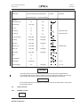

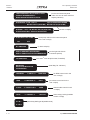
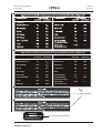
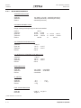


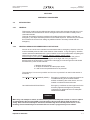
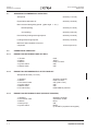


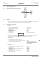

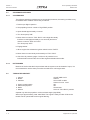
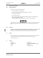


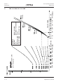
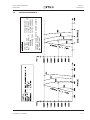
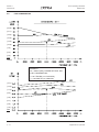

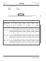

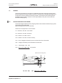
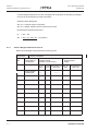

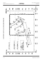


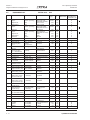

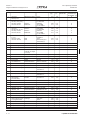


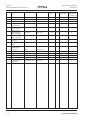


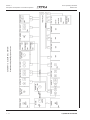


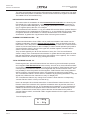

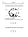
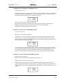
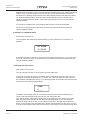


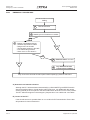
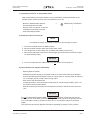
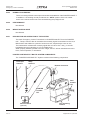


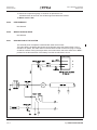


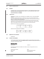


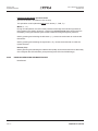


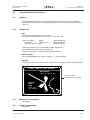
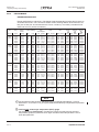
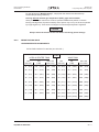


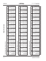
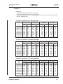


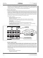


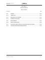


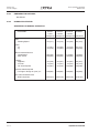
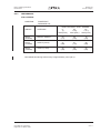


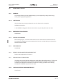


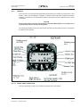


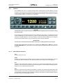


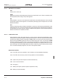
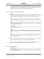
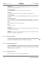


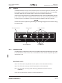
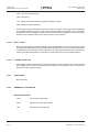


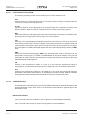
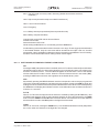


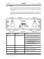


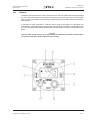
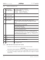


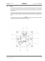
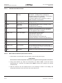

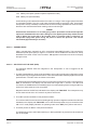

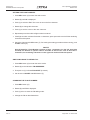
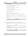


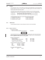
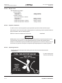
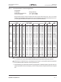
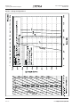
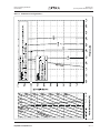

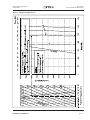

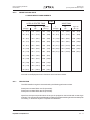
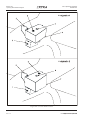


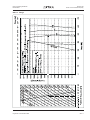
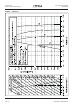
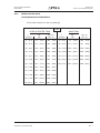


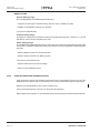


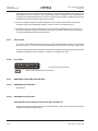


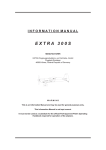

![U.S. Version [Last Updated on: Jun 13th, 2014]](http://vs1.manualzilla.com/store/data/005873845_1-0370c7761d3b42576ec2ae1fd24c9e75-150x150.png)