1
Page 3
Service Manual
plus
Pulse+DIR
Technical Data
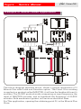
Encoder Interface
Pulse+Dir Interface
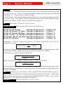
Pulse e Dir Frequency
Encoder Frequency
Freq. Encoder Adjustement
Line Receiver AM26LS33
Line Receiver AM26LS33
Max. 200 Khz
Max. 200 Khz
Divisible for (0.5, 1, 2, 4, 8, 16) FPulse
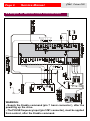
Signal input and output (connector M1)
1 (IN).
Encoder Input Channel CHA
2 (IN)
Encoder Input Channel / CHA
3 (IN)
Encoder Input Channel CHB
4 (IN)
Encoder Input Channel / CHB
5 (IN)
PULSE Input Frequency
6 (IN)
/ PULSE Input Frequency
7 (IN)
DIR Input Frequency
8 (IN)
/ DIR Input Frequency
9 (IN)
0P Exter nal ground
10(IN)
K1 Input
11(IN)
K2 Input
12(IN)
K3 Input
13(IN)
K4 Input
14(IN)
K5 Input
15(IN)
K6 Input
16(OUT)
DR. OK Output Nor mally High(max.5mA)
17(IN)
+Vext Power supply (Optional)
18(IN)
Drive Commond Ground GND
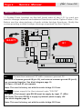
NOTE:--It is not necessary to connect anything to inputs 10-11-1213-14 and 15. These functions are available through soldering
points S5-S6-S7 and S8.
--With soldering point S1 closed input connectors pin 9 (0P) and pin 18 (0S)
are connected together.
--With soldering point S2 closed, nothing is required to be connected to input
17. See Block Diagram page 10.
--With soldering point S9 closed is enabled the function PULSE +DIR input.
With soldering S9 open is enabled the MASTER ENCODER ( cha, chb) in
the pulse + dir inputs.