1
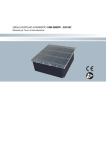
FAN AIR MODULE FAM 6000-I 400-3+N-50 Hz
Operating and Service Manual
MADE IN ITALY
PRESENTATION
This service manual gives all information requested for the knowledge, the correct use and the correct maintenance of all devices described in this Extraction Air Device.
In case of no observance of the Manual’s contents, the Manufacturer will stop any guarantee on the
damaged product.
In case of very difficult maintenance or revision, it is recommended to request the direct intervention of the Manufacturer - that is, however, always at disposal for any suggestion finalized
to the solution of the problem.
WARRANTY
All our products are guaranteed for 12 months after purchase’s date. The reparations under warranty do not change the warranty period. The warranty concerns defects of materials that compromise
the function of product, reducing the efficiency or cancelling the effect of the device. The warranty
is recognised if the fault is reported within 2 days after the appearance.
The warranty does not include faults provoked by:
1 - physical/chemical characteristics of the ambient in which the device operates.
2 - not correct application of our instructions reported in this manual.
3 - storage conditions non in accordance with this manual.
4 - reparations carry out by not authorised service personnel.
And than, the warranty is also not applicable if:
5 - the Serial Number is not readable.
6 - the Customer has not complied to all obligations with the Manufacturer, updated to the service
intervention.
WARRANTY EXCLUSIONS
The warranty is void in case of:
1 - error handling of the operator.
2 - damage due to uncorrected service operation.
3 - replacement of not original spare parts.
4 - the operator did not follow the information indicated in this manual.
Also damages due to negligence, neglect, bad and inappropriate use of the machine exclude the warranty. The elimination of safety devices will cause, automatically, the void of warranty and of any
responsibility from the Manufacturer.
LEGISLATION REFERENCES
The machines, object of this Service Manual, have been made in accordance with EU Directives,
reported in the rear page of this Manual.
Climatel (Padova)
di Giuseppe Giraldo
Index
Pag. 0
Pag. 0
Pag. 0
Pag. 0
Pag. 1
Pag. 1
Pag. 2
Pag. 3
Pag. 3
Pag. 4
Pad. 5
Pag. 5
Pag. 5
Presentation
Warranty
Exclusion of warranty
Normative References
FAM 6000-I module
Air distribution
Air distribution
Fan Air Module FAM 6000-I
Illustrative figures
Illustrative figures
Premise
Use conditions
Installation and connections
Pag. 5 Description of FAM 6000-I
Pag. 6 TAB. 1 - Technical characteristics
Pag. 6 Functional diagram
Pag. 6 Electrical Diagram
Pag. 7 EC Fan with digital control
Pag. 7 Start up
Pag. 7 Management of FAM 6000-I
Pag. 8 Management of FAM 6000-I
Pag. 9 Shut-off
Pag. 9 Ordinary and extraordinary Maintenance
Pag. 9 Standard spare parts
Pag. 9 Disposal
Last Cover: Conformity Declaration
Note 1
The technical characteristics of FAM could be changed by the Manufacturer without notice.
To size the electrical cables and for service interventions it is necessary to follow this Service Manual, annexed
to the machine.
Note 2
All activities, as: Installation, Start-up/Adjustment and Maintenance, must be done by skilled workers or, as
choice, by Service of Manufacturer or by there representatives.
FAN AIR MODULE FAM 6000-I
• Using outdoor air for cooling of technological rooms
• Distributes the environment air, in UNDER or DISPLACEMENT version (see figures below)
Fig. 1
FAM 6000-I (UNDER version)
Air distribution with overpressure motorized damper
Outdoor air inlet duct
Damper to remove indoor
warm air
(by customer)
Fresh/cold
air inlet
FAM 6000-I - 400-3+N-50 Hz
Fig. 1a Motorized
damper
FAM 6000-I
Server
Server
Server
1
Fig. 2
FAM 6000-I (UNDER version)
Air distribution with FAM 6000-E
Outdoor air inlet duct
(by the customer)
Fresh/cold
air inlet
FAM 6000-E to remove indoor
warm air (see Service manual)
FAM 6000-I
Server
Server
Server
FAM 6000-E
Fig. 2a
Fig. 3
FAM 6000-I (DISPLACEMENT version)
Air distribution with overpressure motorized damper
Outdoor air inlet duct
(by the customer)
Fresh/cold
air inlet
Damper to remove
warm air (Fig. 1a)
FAM 6000-I
Server
Server
Server
Base frame
(by the customer)
Note Motorized damper see Fig. 1a
2
FAM 6000-I - 400-3+N-50 Hz
FAN AIR MODULE FAM 6000-I
1950
Fig. 4
75
0
750
Fig. 5a FAM 6000-I
rear air inlet
side view
FAM 6000-I
1275
1875
1950
air inlet
hole 600 x 600
75
100
FAM 6000-I - 400-3+N-50 Hz
3
Fig. 5b FAM 6000-I
Fan and motorized grille
Fig. 5c FAM 6000-I
air filters and pre-filter
4
FAM 6000-I - 400-3+N-50 Hz
Premise
Before installing the machine, we recommend to read the instruction reported on page 0 of this manual.
Use conditions
The air inlet module, FAM 6000-I, is a standalone unit that draws cold/fresh air from outdoor to achieves a
freecooling effect that removes the heat produced in the technological room. The warm air will be expelled
outdoor.
Installation and connections
The module is located in the proximity of a wall (Fig. 1, 2, 3).
The air intake is via duct (by the customer).
The expulsion of the air can occur in two ways:
- with a motorized damper (Fig. 1, 1a, 3)
- by extractor FAM 6000-E (Fig. 2, 2a)
For the wiring, see Fig. 7. Note: Use a differential switch class B 300 mA.
To install the machine it is mandatory to use suitable Protective Equipment, as:
wear appropriate
work clothes
wear protective gloves
wear safety shoes
Description of FAM 6000-I
The module is made by a steel box (see Fig. 4), stove varnished, that includes:
a) EC Centrifugal fan, directly coupled to a variable speed motor, with different air flows and head pressure
(see TAB.1). This motor is equipped with internal thermal relay, with automatic reset, that intervenes in
case of: electrical, electronic control, thermal overload or mechanical troubles.
b) Microprocessor control device.
c) Optimization of Air flow through continuous speed regulator, 0-10 VDC.
d) Direct cooling with outside air.
e) Structure in sandwich panels, class A0 / A1
f) Pocket high capacity filter, preceded by a metal prefilter
FAM 6000-I - 400-3+N-50 Hz
5
TAB. 1 - TECHNICAL CHARACTERISTICS OF FAM 6000-I 400-3+N-50 Hz + earth
Characteristics
Unit of measure
ESP (External Static Pressure)
Pa
Air flow (at 21 °C, density = 1.2 kg/m³)
Value
m3/h
6000 (nominal)
Cooling capacity (*)
kW
24,9
Electric Supply (VAC +/- 10%) (EN 60204-1)
V / Ph /Hz
400 / 3+N / 50
Min Electric absorption
A
0,1
Electronically controlled Fan (EC Fan)
Max Operative Power input
Max Electric absorption FLA
n°
kW
A
200
1
1,51
4,0
Dimensions (W x D x H)
mm
750x750x1950
Limits of use
°C
-20 ÷ +50
Weight
kg
220
* Cooling capacity refers to the following conditions: Outdoor Temp. 12°C and Indoor Temp. 24 °C
Fig. 6 - Functional diagram
Fig. 7 - Electrical Diagram for FAM 6000-I
Note: Use a differential switch Class B 300 mA
See Diagram inside
the electrical panel of the machine
LEGEND
1) Fan
2) Electrical panel
3) Air filter + metal prefilter
4) Damper
5) Noise absorption partitions
6
FAM 6000-I - 400-3+N-50 Hz
Variable speed fan with digital control
The module FAM 6000-I is equipped with a special high efficiency fan which allows to contain significantly consumption and energy costs operation, making it even more convenient to the Freecooling effect it produces.
EC fans (electronically commutated DC motors) have the additional advantage of being adjustable, thus allowing the following benefits, according to the actual demands of the individual user:
- Control of the air flow;
- Control of available static pressure;
- Optimization of sound output;
- Optimization of power consumption.
Fig. 8 - Electrical diagram of Fan speed Regulator
Rpm
max 1400
0
10
1
VDC
External control: 1-10 VDC
Start up
After connecting FAM module, in accordance with electric diagram inside the machine, start the FAM closing
the power switch QS (see electrical diagram).
Adjust the fan speed by applying a signal between 1 and 10 VDC depending on the needs of the environment,
as well as the pressure drop of the outdoor air intake and of the expulsion air module.
Fig. 9
Management of FAM 6000-I
Enabling the fan
100%
ON
Note: OFF = FAM’s Ventilator is off
ON = FAM’s Ventilator is on
0%
OFF
∆T = 3 K
∆T = Indoor Temp. - Outdoor Temp. [K]
FAM 6000-I - 400-3+N-50 Hz
7
Fig. 10
Management of n°1 FAM 6000-I
Combined action with other Conditioners (AC)
Modulating control
100%
ON
FAM
0%
AC 1
AC 2
AC n
OFF
Indoor Temp.
Set Point SP1
1/ 2 Proportional Band B1
Fig. 11
SEQUENTIALLY management of FAM 6000-I
Combined action with other Air Conditioners (AC)
100%
ON
FAM 1
FAM 3
FAM 2
AC 1
0%
AC 2
AC n
OFF
Indoor Temp.
Set Point SP1
1/ 2 Proportional Band B1
Fig. 12
PARALLEL management of FAM 6000-I
Combined action with other Conditioners (AC)
FAM 3
FAM 2
100%
ON
FAM 1
AC 1
0%
AC 2
AC n
OFF
Indoor Temp.
Set Point SP1
1/ 2 Proportional Band B1
8
FAM 6000-I - 400-3+N-50 Hz
Shut-off
Open the power switch QS: see electrical diagram inside the machine.
Maintenance
IMPORTANT: it is strongly forbidden to access to the interior part of FAM when the fan is running!
Wear appropriate
work clothes
Wear protective gloves
Wear safety shoes
Do not approach
the hot surfaces
1- Ordinary maintenance and Control
Check every 6 months at least the fan electrical absorption (to compare with data of TAB.1).
Note: This control must be done without changing the FAM running conditions: openings of cabinet produce
air by-pass and amperage modifications.
2- Extraordinary Maintenance (
)
Where fan shows to high absorption or to high noise, intervene with expert personnel, as indicate on Note 2, page 1.
Standard Spare Part for FAM 6000-I (*)
EC Fan
Air filter
Air metallic prefilter
Motorized damper
Electronic control
(*) Before requesting spares, check any reference stamped on the component.
Disposal
Disassembly / Scrapping
User, according to CE guidelines or to own country regulations, is responsible of disposal of the whole machine or also part of it.
In case of scrapping the entire machine or parts of it, you should take all safety precautions necessary
to avoid the risks associated with the decommissioning of industrial machinery.
This operation must be done following all safety precautions, specially during the following phases:
- Disassembly of machine from the operative site.
- Transportation and movement.
- Disassembly
- Separation of single components.
Separation of materials and their recycling or disposal it is mandatory to apply the National and Regional Rules
regarding disposal of solid industrial waste.
ATTENTION
Disposal of components and materials
In case of scrapping, according to local regulations, the customer must use special cautions regarding the
disposal of:
- PVC
- ELECTRICAL CABLES
- STEEL
IMPORTANT NOTICE: Toxic or corrosive substances are not present in this machine.
FAM 6000-I - 400-3+N-50 Hz
9
CONFORMITY DECLARATION
OF MANUFACTURE
IN ACCORDANCE WITH DIRECTIVE 2006/42/CE
Manufacture
Registered / operating seat
OBJECT OF DECLARATION
Space for customized label
DECLARES
The machine in your possession was made in accordance to the following EU Directives:
• Directive machine 2006/42/CE
• Directive low tension 2006/96/CE
• Directive electromagnetic compatibility 2004/108/CE
The person authorized to produce this technical documentation is:
(Legal representative)
Climatel Freecooling
www.climatelfreecooling.com