1
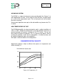
Drawing : - TPC 356
Issue
:-2
Date
: - 19/05/10
DD200
INDUSTRIAL DEHUMIDIFIER
OWNER’S MANUAL
www.eipl.co.uk
Page 1 of 11
Drawing : - TPC 356
Issue
:-2
Date
: - 19/05/10
UNPACKING
Carefully remove the DD200 dehumidifier unit from its transit box and visually
check for signs of transit damage. If there is evidence of damage DO NOT
attempt to operate the unit, call your supplier for advice. Do not discard the
packing, it will be useful when transporting the dehumidifier unit in the future.
INTRODUCTION
Dehumidifiers remove moisture from the air that is circulating through the unit.
The resulting reduction of relative humidity helps prevent rust, rot, mould,
mildew and condensation within the room, or other enclosed spaces where
the dehumidifier is used.
The DD200 is of the desiccant wheel type designed to dry air by passing a
large volume of air, the “process” air through a slowly rotating Silica gel rotor.
Silica gel is a hygroscopic material that absorbs moisture direct from the air.
As the air passes through the rotor the humidity of the air is reduced, whilst
the moisture content of the rotor is increased. A smaller volume of air, the
reactivation air, is heated by an internal heater and passes through a portion
of the rotor in the opposite direction. As this heated air passes through the
rotor it will “reactivate” it by removing the moisture content from the silica gel
material. The reactivation air will leave the humidifier as warm, moist air and
must be vented to outside of the building.
Continuous circulation of the room air through the dehumidifier unit gradually
reduces the relative humidity in the room.
The DD200 dehumidifier is a robust, compact unit designed to control the
humidity in the enclosed space in which it is placed. The casing is fabricated
from Stainless Steel 304 and has been designed for the exacting conditions
which can prevail in offices, shops, houses, restaurants, public houses etc. It
combines lightness and compactness with high reliability and strength. Carry
handles are provide to contribute to its portability.
The unit is thermally protected and will switch off if the maximum operating
temperature of 40ºC is exceeded.
The dehumidifier has a single filter positioned at the air inlet and is used to
clean the air entering the dehumidifier.
Page 2 of 11
Drawing : - TPC 356
Issue
:-2
Date
: - 19/05/10
SPECIFICATIONS
MODEL: DD200
HEIGHT: 340mm
WIDTH: 330mm
DEPTH: 380mm
WEIGHT: 17 Kg
DRY AIRFLOW: 180 M³/HR
WET AIRFLOW: 50 M³/HR
POWER SUPPLY: 115V, 1 ph, 60Hz
POWER 0.8 kW (max)
FINISH: Stainless steel 304
DEHUMIDIFICATION CAPACITY 0.9kg/h
(AT 27°C AND 60% RH)
NOISE 67dB(A)
Page 3 of 11
Drawing : - TPC 356
Issue
:-2
Date
: - 19/05/10
INSTALLATION
POSITIONING:
The DD200 is designed for indoor use. Position the dehumidifier unit in the
center of the room to be conditioned if at all possible.
NOTE: Both the air inlets and outlets of the dehumidifier unit must have clear
space around them and not be obstructed in anyway.
DUCT CONNECTION
The wet air outlet from the dehumidifier must be exhausted to outside of the
room being dried by means of a suitable duct. All duct connections to the
dehumidifier have been designed for connections to standard size ducts.
The duct should be as short as possible to reduce the risk of condensation of
the wet air. The duct should slope downwards away from the unit to stop any
condensed water from flowing back into the unit.
The dry air outlet is also provided with a means of attaching a duct. This can
be used to direct the air towards more severe damp patches.
WIRING:
-WARNINGTHIS APPLIANCE MUST BE EARTHED
The DD200 is provided with a standard plug and is designed to operate from
a 13 Amp supply.
IMPORTANT – The wires in the mains lead are coloured in accordance with
the following code:
GREEN…………….…………EARTH
WHITE..……………………….NEUTRAL
BLACK.....…………………….LIVE
If the supply cord is damaged it must be replaced by qualified Ebac Industrial
Products Ltd personnel or other similar qualified persons in order to avoid
hazard.
Page 4 of 11
Drawing : - TPC 356
Issue
:-2
Date
: - 19/05/10
OPERATION
The electrical controls are located on the front of the unit. They are:
•
•
ON / OFF Switch
0
Dehumidifier OFF
1
Dehumidifier ON
Humidity Switch
M
Dehumidifier in continuous operation
A
Dehumidifier operation by means of an external
humidistat
•
An ammeter is provided to display the current used by the unit.
•
An hour counter is provided to display the total time the unit has been
in operation
•
A socket is provided for connection of a external humidistat
To start the dehumidifier, turn the On / Off switch to position 1.
Turn the humidity switch to position M.
After a slight delay the fan will operate – air can be felt blowing from the air
outlets and the heater will come on.
The unit will operate continuously at this setting.
Note. The DD200 is controlled by an electronic circuit board and uses PTC
(positive temperature coefficient) heater technology to provide the heat
necessary to “reactivate” the rotor.
At switch on, the ammeter will initially show a higher current for a few
seconds, prior to settling to a steady value. This is normal.
If an external humidistat control is fitted, turn the humidity switch to position A.
Depending on the setting of the humidistat, the dehumidifier may switch off as
the relative humidity in the room decreases. As the humidity increase the unit
will automatically switch back on.
The Humidistat plug supplied should be wired using pins numbered 1 & 2.
Pin 3 is not required. See diagram 5010307 at back of manual.
Page 5 of 11
Drawing : - TPC 356
Issue
:-2
Date
: - 19/05/10
AIR MOVING SYSTEM:
The DD200 is a single fan balanced system providing both the “Process” air
and “Regeneration” air flow. As the air passes over the rotor, it will be heated
as a result of the regeneration cycle. The air leaving the unit will be hotter
than the air entering
During normal operation some parts of the dehumidifier may become hot. This
is normal.
HIGH TEMPERATURE CUT OUT:
The DD200 dehumidifier has been designed to work in ambient conditions of
-20ºC to +40ºC. Should the temperature in the room become excessive an
overheat protector will operate, switching off the PTC heaters. The fan and
drive motor will continue to operate. This is a manual reset device. Prior to
resetting the protector, check that the dehumidifier is installed correctly and
the ambient temperature does not exceed 40°C.
See repairs section for details on resetting device.
DEHUMIDIFICATION CAPACITY
Approximate capacity in Kg/h at different inlet process air temperature and
relative humidity (%)
Dehumidification Capacity Kg/h
1.2
80%RH
60%RH
0.8
40%RH
0.4
0.0
-10
0
10
20
Process Air Temperature (°C)
Page 6 of 11
30
Drawing : - TPC 356
Issue
:-2
Date
: - 19/05/10
SAFETY
-WARNING♦ DO NOT ALLOW CHILDREN TO PLAY WITH OR AROUND THE
UNIT. ENSURE THE UNIT IS INACCESIBLE TO CHILDREN
WHEN NOT ATTENDED.
♦ DO NOT USE THIS UNIT IN AN ENVIRONMENT CONTAINING
FLAMMABLE FUMES
♦ DO NOT USE THIS UNIT IF THE CABINET OR POWER CORD IS
DAMAGED
♦ DO NOT INSERT OBJECTS INTO ANY OF THE GRILLES ON
THE MACHINE
♦ DO NOT COVER OR OBSTRUCT AIRFLOW FROM THE
GRILLES
♦ DO NOT OPERATE THE UNIT WITH THE COVERS REMOVED
♦ DO NOT ATTEMPT ANY REPAIRS SHOULD THE UNIT FAIL TO
OPERATE
♦ DO NOT STAND ON THE UNIT
♦ DO NOT LIFT THE UNIT WHEN SWITCHED ON
♦ DO CHECK THE PLUG ON THE EQUIPMENT MATCHES THE
SUPPLY
♦ DO USE THE UNIT FOR THE PURPOSE FOR WHICH IT WAS
DESIGNED
♦ DO ENSURE THE POWER CORD AND SUPPLY IS EARTHED
CORRECTLY
♦ DO USE A RESIDUAL CURRENT DEVICE “RCD” WHERE
POSSIBLE
♦ DO KEEP THE UNIT DRY. NEVER USE A HOSE OR PRESSURE
WASHER TO CLEAN THE UNIT.
Page 7 of 11
Drawing : - TPC 356
Issue
:-2
Date
: - 19/05/10
ROUTINE MAINTENANCE & REPAIR
WARNING:
ENSURE THAT THE POWER CORD TO THE MACHINE HAS
BEEN DISCONNECTED BEFORE CARRYING OUT ROUTINE
MAINTENACE.
SWITCH OFF THE DEHUMIDIFIER APPROXIMATELY 15
MINUTES PRIOR TO REMOVING ANY PANELS, ALLOWING
THE HEATER TO COOL DOWN
To ensure continued full efficiency of the dehumidifier, maintenance
procedures should be performed as follows:
•
We recommend that the filter is checked at least once a month.
Intervals for cleaning or replacement of filters will depend on the
installation
•
Never operate the dehumidifier without the filters as the rotor can be
damaged by dust.
To carryout the following, it is necessary to remove the top cover panel.
This machine should be serviced by qualified Ebac Industrial Products Ltd
personnel or other persons having technical competence in servicing
electrical equipment following the instructions in this Service Manual.
•
The rotor is maintenance free. However, should it be necessary to
clean the rotor, compressed air should be used to carefully blow dirt
from the rotor.
•
The PTC heaters are maintenance free. However should it be
necessary to clean the heaters, compressed air should be used to
carefully blow dirt from the heaters.
•
Check that the fan is firmly secured and that the fan rotates freely.
•
Check all wiring connections.
•
Check the belt tensioning at regular intervals. Adjust when needed by
loosening the four bolts holding the drive wheel and rotating the drive
motor until correct tension is achieved.
•
The overheat protector is located inside the unit, towards the front,
near the rotor. To reset this device press the red button.
•
Should an electrical component fail, consult the Factory Service Center
to obtain the proper replacement part.
Page 8 of 11
Drawing : - TPC 356
Issue
:-2
Date
: - 19/05/10
IF ANY OF THE PRECEDING PROBLEMS OCCUR, CONTACT THE EBAC
INDUSTRIAL PRODUCTS LTD SERVICE CENTER PRIOR TO CONTINUED
OPERATION OF THE UNIT TO PREVENT PERMANENT DAMAGE.
TROUBLESHOOTING
SYMPTOM
Little or no
dehumidification
capacity
Dehumidifier does
not start
CAUSE
REMEDY
Filter clogged
Clean or replace filters
No regeneration heat
Check PTC / OHP
Reduced airflow
Check fan / duct
No rotation of Rotor
Check belt tension / drive motor
Air leakage
Check sealing
No power
Check fuse
Correct switch setting
Drive belt slipping
Check Auto / Manual switch
Check wiring diagram - fault
find & repair
Check belt tension
Drive belt broken
Replace drive belt
Rotor jammed
Check centre shaft, rim of rotor
Drive motor faulty
Check supply /Replace motor
Filter clogged
Clean or replace filters
Fan faulty
Check supply / fan
Ducts blocked
Check duct for obstruction
Low reactivation airflow
Check air path for restriction
PTC faulty
Check PTC / OHP
Fan loose
Check fan is secured firmly
Loose fastenings
Tighten all fastenings
Loose electrical wiring
Rotor does not
rotate
No Dry or Wet Air
Airflow
Low current
displayed on
ammeter
Noisy
Page 9 of 11
Drawing : - TPC 356
Issue
:-2
Date
: - 19/05/10
SPARE PARTS LIST
DESCRIPTION
PART NUMBER
Process Air Fan Motor
3040261
Capacitor for Process Air Fan Motor
3030891
Process Inlet Filter
2050114
Drive Motor
3040260
Capacitor for Drive Motor
3030875
Pulley
3050556
Pulley Belt
3050555
PTC Heater
3031626
Overheat Protector
3477026
Desiccant Wheel
3020708
PCB Controller
1619600
Mains Cable
3035148
On / Off Switch
3030557
Auto / Manual Switch
3030522
Ammeter
3180100
Hour Counter
3030779
Humidistat Socket
3033807
Humidistat Plug
3033806
Spare parts available online
www.EIPLDIRECT.com
Page 10 of 11
Drawing : - TPC 356
Issue
:-2
Date
: - 19/05/10
UK Head Office
American Sales Office
German Sales Office
Ebac Industrial Products Ltd
St Helens Trading Estate
Bishop Auckland
County Durham
DL14 9AD
Ebac Industrial Products Inc
700 Thimble Shoals Blvd.
Suite 109, Newport News
Virginia, 23606-2575
USA
Ebac Industrial Products Ltd
Miraustra 64 – 66
13509
Berlin
Germany
Tel: +44 (0) 1388 664400
Fax: +44 (0) 1388 662590
Tel: +01 757 873 6800
Fax: +01 757 873 3632
Tel: +49 3043 557241
Fax: +49 3043 557240
www.eipl.co.uk
[email protected]
www.ebacusa.com
[email protected]
www.eip-ltd.de
[email protected]
Page 11 of 11