1
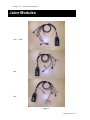
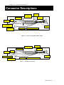
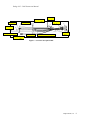
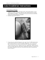
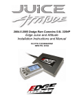
Edge Juice and Attitude
Installation Instructions and Manual
Dodge 5.9L Cummins 1998.5 - 2002
© 2006, Edge Products, LLC
All rights reserved.
Edge Products, LLC
1080 South Depot Dr.
Ogden, UT 84404
(801) 476-3343
Dodge 98.5 – 2002 Instruction Manual
www.edgeproducts.com
Manual Version 021006
Table of Contents
DISCLAIMER OF LIABILITY .................................................................................................. 3
AFTERMARKET PRODUCTS AND YOUR VEHICLE’S WARRANTY .............................. 3
Connecting to Power ....................................................................................................................... 9
MAP Sensor Connection ............................................................................................................... 12
Connecting the *Posi-Tap® Connector to the VP 44 Injection Pump Wire ................................. 13
VP 44 Pump Detailed View .......................................................................................................... 13
Connecting the Ground Wire......................................................................................................... 19
“Lift Pump” Fuel Pressure Sensor Installation.............................................................................. 19
Data Link Connection ................................................................................................................... 22
Boost Elbow Installation ............................................................................................................... 23
Connecting the Transmission Temp Sensor (Automatic Transmission) ....................................... 24
Connecting the Transmission Temp Sensor (Standard Transmission).......................................... 25
EGT Probe Installation .................................................................................................................. 26
Changing the Attitude Display ...................................................................................................... 34
Two Function Bar Graph Display Sample ............................................................................ 34
Two Function Digital Display Sample .................................................................................. 35
Three Function Digital Display Sample ................................................................................ 35
Four Function Digital Display Sample.................................................................................. 35
Max EGT Setpoint......................................................................................................................... 40
Max Boost Setpoint ....................................................................................................................... 40
Low Boost Fueling Adjustment..................................................................................................... 42
Turbo Cool Down Setup................................................................................................................ 43
Cold Engine Protection ................................................................................................................. 44
Tire Size ........................................................................................................................................ 44
Truck Model Year ......................................................................................................................... 45
Troubleshooting Guide.................................................................................................................. 53
The Juice Module is a high performance product
It is strongly recommended that EGT and boost gauges
Edge Products, LLC
2
Dodge 98.5 – 2002 Instruction Manual
be installed when using this product.
USE THIS PRODUCT AT YOUR OWN RISK.
Do not use this product until you have carefully read the following agreement.
This sets forth the terms and conditions for the use of this product. The installation of this
product indicates that the BUYER has read and understands this agreement and accepts its terms
and conditions
DISCLAIMER OF LIABILITY
Edge Products, LLC and its successors, distributors, jobbers, and dealers (hereafter SELLER) shall in no way be
responsible for the product's proper use and service. THE BUYER HEREBY WAIVES ALL LIABILITY CLAIMS.
The BUYER acknowledges that he/she is not relying on the SELLER’s skill or judgment to select or furnish goods
suitable for any particular purpose and that there are no liabilities which extend beyond the description on the face
hereof and the BUYER hereby waives all remedies or liabilities, expressed or implied, arising by law or otherwise,
(including without any obligations of the SELLER with respect to fitness, merchantability and consequential damages)
or whether or not occasioned by the SELLER's negligence.
The SELLER disclaims any warranty and expressly disclaims any liability for personal injury or damages. The
BUYER acknowledges and agrees that the disclaimer of any liability for personal injury is a material term for this
agreement and the BUYER agrees to indemnify the SELLER and to hold the SELLER harmless from any claim
related to the item of the equipment purchased. Under no circumstances will the SELLER be liable for any damages or
expenses by reason of use or sale of any such equipment.
The SELLER assumes no liability regarding the improper installation or misapplication of its products.
It is the installer's responsibility to check for proper installation and if in doubt, contact the manufacturer.
LIMITATION OF WARRANTY
Edge Products, LLC (hereafter "SELLER") gives Limited Warranty as to description, quality, merchantability, fitness
for any product’s purpose, productiveness, or any other matter of SELLER's product sold herewith. The SELLER
shall be in no way responsible for the product’s open use and service and the BUYER hereby waives all rights other
than those expressly written herein. This Warranty shall not be extended or varied except by a written instrument
signed by SELLER and BUYER.
The Warranty is Limited to one (1) year from the date of sale and limited solely to the parts contained within the
product's kit. All products that are in question of Warranty must be returned shipping prepaid to the SELLER and must
be accompanied by a dated proof of purchase receipt. All Warranty claims are subject to approval by Edge Products,
LLC
Under no circumstances shall the SELLER be liable for any labor charged or travel time incurred in diagnosis for
defects, removal, or reinstallation of this product, or any other contingent expenses.
If the BUYER sends back a failed unit that is out of warranty and chooses to buy a refurbished unit, the refurbished
unit will only carry a 60 day warranty. If the BUYER purchases a new unit at a predetermined discounted rate, it will
have the standard 1 year warranty.
Under no circumstances will the SELLER be liable for any damage or expenses insured by reason of the use or sale of
any such equipment.
IN THE EVENT THAT THE BUYER DOES NOT AGREE WITH THIS AGREEMENT: THE BUYER
MAY PROMPTLY RETURN THIS PRODUCT, IN A NEW AND UNUSED CONDITION, WITH A
DATED PROOF OF PURCHASE, TO THE PLACE OF PURCHASE WITHIN SIXTY (60) DAYS
FROM DATE OF PURCHASE FOR A FULL REFUND.
THE INSTALLATION OF THIS PRODUCT INDICATES THAT THE BUYER HAS READ AND
UNDERSTANDS THIS AGREEMENT AND ACCEPTS ITS TERMS AND CONDITIONS.
AFTERMARKET PRODUCTS AND YOUR VEHICLE’S WARRANTY
Edge Products, LLC
3
Dodge 98.5 – 2002 Instruction Manual
Many of our customers ask, “Will your product void my vehicle
manufacturer’s warranty?” While the answer is straightforward from a legal
standpoint, we also want to educate our customers (and after-market
consumers) on some industry realities and offer some common sense
precautions to minimize your risk.
Consumers of aftermarket products are protected by The Federal
Magnusson-Moss Warranty Act. The Act states that if something breaks on
your car and you take it in for warranty repair, the dealer must honor your
warranty unless they can prove that whatever modifications you have added
to your car actually caused the problem. Please keep in mind that towing in
anything higher than level two and hard driving in levels four and five are
not recommended.
While as a consumer, you have strong legal protection with regards to your
vehicle’s warranty, there is also a practical reality that different automotive
manufacturers and dealers have greatly varying views on aftermarket
products, in particular those that produce horsepower, such as performance
enhancement chips, modified intake manifolds, or aftermarket exhaust
systems. There are dealers and manufacturers out there that will use the
presence of a horsepower upgrade to void your vehicle’s warranty. They
will do this regardless of whose product you are using. Any aftermarket
company that does not acknowledge this is misleading you.
The bottom line is that while the law protects the consumer and provides for
enforcement of the warranty, it is very difficult for most people to hire an
attorney and fight a voided warranty. Edge recommends that you always
disconnect and remove your module and monitor when you take your
vehicle to a dealer for warranty work in order not to interfere with
Diagnostic equipment.
Edge Products, LLC
4
Dodge 98.5 – 2002 Instruction Manual
About the Dodge VP44 Juice
Supplied Items:
1. Edge Juice Module
2. Main Wiring Harness
To Engine Compartment- Black to Ground; Gray to Fuel Injection Pump; Map Sensor
Connection; Data Link Connection.
Inside Cab - Yellow to Fuse Number 9 (engine)
3. Fuel Injection Pump Connector
4. Four Wire Ties
5. Two Velcro Strips
6. One Hose Clamp
7. One 90° Brass Fitting
8. Two Male Spade Fuse Connector
Tools Required:
Knife
2-3 ft. of wire (fishing)
Pliers (needle nose)
Phillips Screwdriver
Flat tip Screwdriver
3/8” Drive Torque Wrench
1/2” Wrench
3/8” Drive Ratchet & Sockets
1/4” Socket
5/16” Socket
7/16“ Deep Well Socket and Ratchet
10 mm Socket
13 mm Socket
Silicone Sealer
Edge Products, LLC
5
Dodge 98.5 – 2002 Instruction Manual
Juice Modules
1998.5 - 2000
2001
2002
Figure 1
Edge Products, LLC
6
Dodge 98.5 – 2002 Instruction Manual
Connector
Descriptions
Connect
Descriptions
The Map Sensor
Connector 1998.5
2000
Attitude
Connectio
EGT
Probe
Ground
+12V
to
Transmissi
on temp
Injection Pump
Connection
To Juice
Module
The data link
connector 98 5 to
Fuel
Turbo Timer Connector- To
Figure 2 - Connector description 1998.5 – 2000
The Map Sensor
C
t 20001
Ground
C
Attitude
ti
EGT Probe
C
ti
+12V
t
Transmissi
t
To Juice
M d l
Injection Pump
The data link
t 2001
Fuel
Turbo Timer Connector- To spare
Figure 3 – Connector description
Edge Products, LLC
7
Dodge 98.5 – 2002 Instruction Manual
The Map Sensor
C
2002
+12V to
Attitude
C
i
Ground
EGT
P b
Transmissi
Injection Pump
Fuel
Turbo Timer Connector To spare
To Juice
M d l
The data link
2001
Figure 4 – Connector description 2002
Edge Products, LLC
8
Dodge 98.5 – 2002 Instruction Manual
Juice Installation Instructions
Connecting to Power
1. Using the ½” wrench, loosen both negative battery cable clamp fasteners, remove
cables from the battery posts and set each to the side. NOTE: DO NOT reconnect
until installation is complete. Connecting power may cause fault code in the ECM,
which only an authorized dealer can remove.
2. Install fuse clip on fuse (Figure 5).
Figure 5 – Fuse tap installed on fuse
3. Connect the power cable (See Figure 6) to the “spare” fuse (15 AMP) inside the fuse
panel located on the driver’s side of the engine compartment. Note: Not all trucks
have a spare fuse location. If your truck does not have a spare fuse designation –
Connect the fuse tap to any 15 Amp fuse such as the “Quad Light”. Remove the fuse
panel cover and the spare fuse and attach the supplied male spade fuse connector onto
the terminal. Reinstall the stock fuse with connector back into the fuse panel (this
may be a tight fit).
Edge Products, LLC
9
Dodge 98.5 – 2002 Instruction Manual
Use supplied fuse tap and
connect to the “spare”
f
Figure 6 – Power wire attachment to spare fuse location in
Edge Products, LLC
10
Dodge 98.5 – 2002 Instruction Manual
Routing the Turbo Timer Cable
1. The Turbo-Timer cable routes from the engine compartment to inside the cab - Cut a
1/2” slit in the firewall grommet. Automatics- easy access is the clutch hole
grommet located to the left of the firewall brake hole. Manuals or Automatics- Use
the large vehicle wiring harness grommet on the firewall. Fish the supplied cable
through the slit from the engine compartment into the cab. Route the supplied yellow
wire up into the fuse panel fuse #9 (Engine) on the driver side of the dash board. (You
must open the door to access this panel.) - See Figure 7
Install connector on fuse clip
In-cab fuse panel.
Connect to fuse 9
Figure 7 – Connection of the turbo-timer keep alive tap inside cab fuse box
Edge Products, LLC
11
Dodge 98.5 – 2002 Instruction Manual
MAP Sensor Connection
1. Disconnect the stock wiring harness from the
boost sensor located to the rear of the fuel filter
housing near the top of and on the engine
block. Plug the supplied MAP sensor
connector into the boost sensor and the engine
wiring harness connector into the supplied
MAP sensor connector. The MAP sensor
shown in the image is for a 2001, the 1998.52000 are a different sensor but in the same
location. See figure 8 and 9.
MAP Sensor
& 2000-2002
Data Link
1998.5-1999 Data
Link
Figure 8
Map Sensor
Connection
Front of vehicle
Figure 9
Edge Products, LLC
12
Dodge 98.5 – 2002 Instruction Manual
Connecting the *Posi-Tap® Connector to the VP 44 Injection
Pump Wire
NOTE: Although attaching the
Juice cable to the VP 44 pump
control wire is optional; not tapping
into the VP 44 pump prevents the
Juice module from increasing the
output of the Cummins engine to
it’s full potential and will result in
limited horsepower and torque
gains.
Unbolt the casting that attaches to the
Throttle Position Sensor (TPS) housing to
expose the injection pump and the
associated control wire.
Unbolt the casting that
attaches to the TPS to
get better access to the
injection pump control
wire.
Figure 10 – Throttle Position Housing
VP 44 Pump Detailed View
Before connecting the Juice to the Bosch VP 44 high pressure pump we will try to show how
and where to attach the Posi-Tap® connection. The pictures below are of a Bosch VP 44
pump that has been removed from a truck. This is the same pump used on Cummins engines
for model year trucks from 1998 ½ to 2002.
The VP 44 is the injection pump that supplies each injector with a metered amount of fuel.
The Juice module will control the pump directly under varying criteria determined by load
conditions and power level selection. In order to control the pump more directly, the Juice
module needs to be electrically attached to the VP 44 pump. In order to attach the juice
module to the VP 44 pump, the control wire must be pierced with a wire from the Juice
harness.
Edge Products, LLC
13
Dodge 98.5 – 2002 Instruction Manual
Wire Bundle Two – Do not
modify this bundle
Wire Bundle One Cut the protective
jacket on this bundle
to expose TWO wires
Figure 11 – VP 44 Fuel Pump
There are two wire bundles visible on the outside of the injection pump. The wire bundle most
visible when the Throttle Position Sensor is removed is the wire bundle that we will be
dealing with when we attach the Juice to the pump.
Both bundles contain two wires each which are underneath the protective jacket. About an
inch of the jacket covering wire bundle number one (Figure 11) must be cut back to expose
the control wires.
Edge Products, LLC
14
Dodge 98.5 – 2002 Instruction Manual
Wire Bundle One Connects to the “top” or
“Pressure Head” of the
injection pump
Wire Bundle One Contains the wire that will
be connected to the Juice
Locate this wire and install
the Posi-Tap® from the
Juice Wire harness
Figure 12 – Wire bundle one detailed view
Edge Products, LLC
15
Dodge 98.5 – 2002 Instruction Manual
Wire Bundle One About one inch of
shielding removed
to expose both
control wires
Figure 13 – Cut the woven shielding back by about one inch
Using a sharp knife or razor carefully slice back the insulation that covers both pump wires
contained in wire bundle number one (see figure 11 - 14 to identify wire bundle number one).
Locate the TOP injection pump wire identified in Figure 12 and 14. After exposing the
injector control wires in bundle one, unscrew the “top” of the Posi-Tap and place the wire to
be tapped in the slot provided in the cap of the Posi-Tap. Place a single drop of RTV Silicone
Sealer in the CAP of the Posi-Tap. There should be enough silicone sealer
so that when the cap is installed on the Posi-Tap body some of the sealer is pushed out around
the edges of the wire.
The silicone sealer will provide a water tight seal when the body of the wire tap is screwed to
the cap of the Posi-Tap device. When the body of the tap is inserted through the wire
insulation the insulation will act as a wiper to remove the sealer from the pin inside the PosiTap and the pin will make a good connection with the wire inside the insulation.
Edge Products, LLC
16
Dodge 98.5 – 2002 Instruction Manual
Once the silicone sealer is installed in the cap, pre-twist the body of the Posi-Tap counter
clockwise (looking at the pointed end of the Posi-Tap located on the wire harness) with about
seven full turns. This will pre-load the wire so that when the body of the Posi-Tap is installed
on the cap, the wire will not remain twisted in the wire harness.
Wire Bundle One Place the top wire from
Wire Bundle number one in
the slot provided in the
“cap” of the Posi-Tap®.
Pre-twist wire seven turns
clockwise prior to installing
Figure 14 – Installing Posi-Tap® on to the VP 44 control wire
Edge Products, LLC
17
Dodge 98.5 – 2002 Instruction Manual
Figure 11 - *Patent #5,228,875 5,695,369 5,868,589 Jap 2881414, Aus
708700 Tia 103534 and others pending.
Install the Posi-Tap® on to the
uppermost wire of the injection
Location of the
injection pump
control wire that
needs to be
Front of
vehicle
Figure 16 – Completed installation of the Posi-Tap®
Edge Products, LLC
18
Dodge 98.5 – 2002 Instruction Manual
Connecting the Ground Wire
Connect the Ground wire to the NEGATIVE side of the battery by connecting the terminal to the
battery as shown below.
Connect the Juice Ground to the
NEGATIVE battery post
Front of vehicle
Figure 17 – Connect the ground lead of the Juice Module to the Negative side of the
battery
“Lift Pump” Fuel Pressure Sensor Installation
Important Note: If you lack experience or tools to bleed the fuel system take the truck
to an experienced mechanic for installation of the fuel pressure sensor!
The fuel system on the Cummins engine is comprised of several components. Two of the
major components are the LIFT pump which pumps fuel from the fuel tank to the Bosch
VP-44 high pressure injector pump that pressurizes the fuel to the correct pressure and
then directs fuel to the injectors.
The fuel that is pumped to the injectors also acts as a lubricant for the Bosch VP-44 high
pressure pump. A loss of fuel pressure to the high pressure pump may result in permanent
damage to the high pressure pump.
A fuel pressure sensor has been added to the Juice / Attitude combination to alert the
driver to the possibility of damage to the high pressure pump if a loss of pressure is
detected. A pressure sending unit is to be placed between the lift pump and the high
Edge Products, LLC
19
Dodge 98.5 – 2002 Instruction Manual
pressure pump which is then monitored by the Juice / Attitude combination. This allows
continuous monitoring of the fuel pressure from the LIFT pump. The fuel pressure can be
displayed directly on the Attitude and a Low Fuel Pressure alert can be set on the Attitude
to alert the driver to loss of pressure to the high pressure pump – It is recommended that
the pressure not drop below 10psi at idle and not drop below 4psi while driving.
In order to insert the fuel pressure sensor, the Test Port Fitting must be removed from the
VP 44 housing (See figure 18) and replaced with a banjo bolt (provided) that allows the
pressure sensor to be coupled to the fuel line.
Supplied banjo bolt
Use a 3/4 inch
(19mm) open end
Fuel pressure sensor
– Use a one inch
open end wrench
Front of
Fuel return
b
Figure 18 – Installation of fuel pressure sensor
Edge Products, LLC
20
Dodge 98.5 – 2002 Instruction Manual
Fuel pressure sensor –
Use a one inch open
end wrench
Supplied banjo bolt
Use a 3/4 inch (19mm)
open end wrench
Fuel return banjo
Front of vehicle
Figure 19 – Fuel pressure sensor model year 98.5 only
When the Test Port Fitting is removed, fuel can drain out of the VP 44 pump (especially
applicable to model year 2000 to 2002) and air can enter the line or enter the VP 44
pump.
In order to minimize the amount of air that is let into the fuel system, pre-install the fuel
pressure sensor onto the supplied banjo bolt before removing the stock banjo fitting from
the pump. Prior to removing the stock banjo bolt from the fuel system, Pre-install one
washer with integral neoprene seal onto the supplied banjo bolt.
Remove the stock banjo bolt from the VP 44 pump and replace with the supplied banjo
bolt with the pre-installed neoprene washer and fuel pressure sensor. As quickly as
possible install the banjo bolt through the fuel line and install the other supplied neoprene
washer onto the banjo bolt and thread it into the VP 44 pump. Tighten to the appropriate
torque specifications (18 ft-lbs).
Edge Products, LLC
21
Dodge 98.5 – 2002 Instruction Manual
FAILURE TO REMOVE AIR FROM THE
FUEL SYSTEM MAY RESULT IN
DAMAGE TO THE VP 44 FUEL PUMP
IT IS CRITICAL THAT THE AIR INTRODUCED INTO THE FUEL LINE BE
REMOVED FOR THE FUEL SYSTEM TO OPERATE PROPERLY.
Use this bleeding procedure at the end of the installation. Trying to
bleed the fuel system half way through the installation could cause a
check engine light.
In order to remove the air from the system, loosen BUT DO NOT REMOVE the
overflow valve banjo fitting that connects to the return line. Place a shop rag or towel
around the banjo fitting to catch excess fuel.
•
Turn the ignition key to CRANK position and quickly release the key to the ON
position. DO NOT START THE ENGINE! The fuel lift pump will operate for up
to 25 seconds. Once this procedure is complete, tighten the return line banjo
fitting to 24 Nm (18 ft-lbs.) torque.
•
Attempt to start the engine – The engine may be very noisy or run erratic for a
few minutes. Keep an eye on the fuel pressure as displayed on the Attitude. If the
pressure drops below four 4psi, or the engine quits running, re-bleed the return
line of the VP 44 pump. If the engine still does not start, remove and check the
fuel filter. If the filter is dirty or damaged, replace the filter.
CAUTION:
• Do not engage the starter motor for more than 30 seconds – Allow two minutes
between cranking intervals.
• Although it is rare, on occasions the LIFT pump may fail to prime after the banjo
bolt has been replaced signifying a possibility of a warn pump. In this rare
instance the LIFT pump should be replaced.
Reinstall the throttle bracket onto the fuel injection pump using the three bolts. Using the
torque wrench and 13mm socket, torque these bolts to 18 ft-lbs.
Data Link Connection
The Data Link connector is located in different locations based on the year of the truck:
• 98.5 - 99 the triangle shaped connector is located on the drivers side of the engine
in the wiring harness near the power steering pump.
Edge Products, LLC
22
Dodge 98.5 – 2002 Instruction Manual
•
2000 - 2002 the three pronged flat connector is located on top of the fuel lift pump
that is located on the driver’s side of the engine directly below the MAP sensor.
Note: on some 2001 trucks the
connector is located on the drivers
side of the engine in the wiring
harness near the power steering
pump.
Replace the protective plug on the truck
data link with the corresponding data link
connector on the Juice harness (Figure 20).
MAP Sensor
& 2000-2002
Data Link
Boost Elbow Installation
1. Using the 5/16” socket, loosen the two
clamps securing the air induction hose
to the air filter housing and the turbo
inlet. Remove the hose and set it aside.
2. Using the pliers, remove the crimp
style clamp from the hose on the brass
fitting located on the now exposed
lower front side of the turbocharger.
Remove the hose from the brass fitting
1998.5-1999 Data
and dispose of the crimp style clamp.
Link
3. Using the 7/16” wrench, unscrew the
Figure 20
stock brass fitting out of the
turbocharger housing. Using the 7/16”
wrench, install the supplied brass fitting, tighten-be careful not to over-tighten. Slip the
supplied hose clamp onto the stock hose, install the stock hose onto the supplied brass
fitting and tighten the hose clamp with the ¼” socket. Reinstall the stock air hose onto
the air filter housing and turbocharger inlet. Using the 5/16” socket, tighten both clamps
securely.
Note: On 2001+ vehicles with automatic transmissions, the turbo waste gate is a solid line and
does not have a brass elbow to be replaced.
Edge Products, LLC
23
Dodge 98.5 – 2002 Instruction Manual
Connecting the Transmission Temp Sensor (Automatic
Transmission)
Unbolt the stock plug from passenger side of the transmission using a 7/16 inch (11mm) wrench
(see Figure 21). Note: A small amount of transmission fluid will leak from the outlet. Apply
Teflon tape to the threads of the transmission temperature sensor. Using a ½ inch wrench, thread
the Edge Products transmission oil temp sensor and connect the cable using the supplied nut.
From the top of the engine, route the transmission temperature sensor along the factory wiring
harness and over the top of the transmission directly behind the bell housing of the transmission
and secure with supplied wire ties.
Transmission Temp Sensor
installed on passenger side
towards the front of the
transmission close to the
transmission dip stick tube
Dipstick tube
Front of vehicle
Figure 21 – Automatic Transmission Temperature Sensor
Edge Products, LLC
24
Dodge 98.5 – 2002 Instruction Manual
Connecting the Transmission Temp Sensor (Standard
Transmission)
NOTE: When the Power Take-Off (PTO) plate is removed ALL of the gear lube from the
transmission will drain out – Ensure that you have the CORRECT replacement oil prior to
removing the PTO plate. See the Dodge service manual for replacement gear lube type.
1. Using a 14 mm wrench, remove the lowest bolt on the PTO cover plate and drain the
transmission fluid.
2. Unbolt the remaining five bolts to the PTO cover plate and remove it completely.
3. Using a 5/ 16” or 21/64” drill bit, drill a hole in the PTO cover plate in the location
shown in figure 22. Using a 1/8” NPT tap, thread the hole in the PTO cover plate. Apply
Teflon tape or pipe thread sealant to the transmission temperature sensor and thread it
into the PTO cover plate.
4. Clean the surface of the PTO cover plate and transmission and apply an automotive
gasket silicone to the plate surface that will come in contact with the transmission.
5. Re-attach the plate cover to the transmission and connect the sensor cable to the sensor.
6. Refill the transmission with fluid. (Contact your Chrysler dealer for correct fluid and
fluid amount).
Up
Front
Figure 22 – Manual Transmission Temperature Sensor Location
Edge Products, LLC
25
Dodge 98.5 – 2002 Instruction Manual
EGT Probe Installation
1. The EGT probe must be mounted before the turbo for the Juice safety features to
operate properly. Using a 5/ 16” or 21/64” drill bit, drill a hole in the exhaust manifold
as shown in figure 23. Use a 1/8” NPT tap to thread the hole.
2. Once the hole is drilled and tapped, run the motor at idle for 10 to 15 seconds to clear the
few remaining shavings from the manifold.
3. Screw the provided threaded adapter into the manifold and tighten it with a 9/16” end
wrench. Slide the EGT probe through the threaded adapter and into the exhaust
manifold. Tighten the EGT sensor with a 5/8” end wrench (see figure 24).
4. Slide the provided heat shrink over the red and yellow wires of the EGT cable. Connect
the red wire of the probe to the red wire on the Juice module with the nut and bolt. Using
a heat gun, or a lighter, shrink the tubing. Repeat the same steps for the yellow wire.
This is the EGT
probe installed in
the exhaust
manifold.
Figure 23 – EGT probe location
Edge Products, LLC
26
Dodge 98.5 – 2002 Instruction Manual
Figure 24
Final Inspection and Operation
1. Recheck all connections, fittings and fasteners for proper installation.
2. Using the supplied wire ties, secure the wiring harness from possible damage.
3. Reconnect both negative battery cables. Using the ½” wrench, tighten both fasteners
securing the cable clamps to the battery posts.
4. Turn the ignition key on. The Attitude should light up and display the user agreement
screen.
5. Bleed the fuel system as described in the “Lift Pump” Fuel Pressure Sensor Installation
section.
6. Start the engine and inspect the fuel pressure and transmission temperature sensors
for leaks. If the engine does not start, try to bleed the fuel system again.
7. If the check engine light appears, proper connections may not have been made to the
MAP sensor.
8. If the Juice does not function as described above, check the trouble shooting guide at
the end of this manual, or contact Edge Products technical support center 888-360EDGE.
Edge Products, LLC
27
Dodge 98.5 – 2002 Instruction Manual
This page intentionally left blank
Edge Products, LLC
28
Dodge 98.5 – 2002 Instruction Manual
Attitude Instructions
Edge Products, LLC
29
Dodge 98.5 – 2002 Instruction Manual
About the Attitude
The Attitude allows you to monitor the performance of your vehicle’s vital engine
components and output values. The following parameters can be displayed on the main
Attitude screen:
•
Backdown %
•
Engine Control Module Voltage
•
EGT (exhaust gas temperature)
•
Engine Coolant Temp
•
Engine Oil Pressure (98.5 - 2001)
•
Fuel Pressure (Pressure of the fuel “lift pump”)
•
Fuel Temperature ( Measured in the VP44 injector pump)
•
Intake Air Temp
•
Engine Load % (Only on later models)
•
Module Temperature (Internal temperature of Juice module)
•
RPM
•
Speed MPH
•
Throttle %
•
Transmission Temp
•
Turbo Boost Pressure
Edge Products, LLC
30
Dodge 98.5 – 2002 Instruction Manual
Power Gains
The following power gains are representative of an actual test vehicle. These gains were
measured on a Mustang Dynamometer at an altitude of 4400 ft above sea level, and represent
power delivered to the rear wheels of the test truck. The only modification made to the test truck
was the addition of the Edge Juice module. Power gains may vary between trucks and
atmospheric density.
Horsepower
Level 0: Stock
Level 1: 40 HP
Level 2: 60 HP
Level 3: 80 HP
Level 4: 100 HP
Level 5: 120 HP
Torque
Stock
150 ft-lbs Torque
200 ft-lbs Torque
250 ft-lbs Torque
300 ft-lbs Torque
350 ft-lbs Torque
Warning: It is strongly advised that you do not combine, or “stack”
chips to gain more horsepower.
Dodge VP44 Attitude Getting
The Attitude monitor connects under the hood to the Edge Juice module. Follow these steps to
install the Attitude:
1. Place the Attitude monitor on the dash of the vehicle approximately where you would like to
mount it. The Attitude cable can be routed through the same grommet in the fire wall that was
used for the turbo timer cable. Connect the Attitude to the Edge Juice module by snapping
together the cables with the green connections. Secure any excess cable to prevent entanglement
with moving engine parts.
2. Determine where you want to mount the Attitude mounting bracket and insert it into the
dashboard. The bracket fits well in the seam of the dash board by separating the seam slightly and
sliding in the bottom portion of the bracket until it snaps into place (see figure 1 and 2). The
following pictures demonstrate how to best mount the Attitude with the new bracket.
Dodge Attitude Manual
31
Dodge 98.5 – 2002 Instruction Manual
Supplied attitude bracket shown in figure 1 and 2
Figure 1
Figure 2
If the Attitude monitor is installed correctly, a screen similar to the following will appear when
the ignition key is in the run position:
Press the <ENT> key to accept the terms and conditions in your Owner’s Manual. A screen
similar to the following appears indicating that your Juice and Attitude were installed
correctly.
32
Dodge Attitude Manual
Dodge 98.5 – 2002 Instruction Manual
Adjusting Juice Power Levels
The Juice power level is displayed in the upper right-hand corner of the screen when vehicle
parameters are being viewed. To adjust the power levels, press the arrow keys to the desired
level. Levels can be changed at any time while viewing vehicle parameters.
To adjust the
Juice power
levels, press
the arrow keys.
The current Juice
power level is
displayed here.
Dodge Attitude Manual
33
Dodge 98.5 – 2002 Instruction Manual
Changing the Display View
Hanging the Attitude Display
The Attitude allows you to view multiple engine parameters on the same screen. To select a
desired view, perform the following steps:
1. Press the [Menu] button until the Setup screen appears:
2. Select the Display option and press the [Enter] button. The following screen appears:
3. Select the desired viewing option by using the up and down arrows and pressing the
[Enter] key. Below are examples of the display options:
Two Function Bar Graph Display Sample
34
Dodge Attitude Manual
Dodge 98.5 – 2002 Instruction Manual
Two Function Digital Display Sample
Three Function Digital Display Sample
Four Function Digital Display Sample
Dodge Attitude Manual
35
Dodge 98.5 – 2002 Instruction Manual
Changing Variables on the Screen
The following is a list of parameters that can be displayed on the Attitude:
•
Backdown %
•
Load % (Only on later models)
•
ECM Volts
•
Module Temp F
•
EGT (exhaust gas temperature)
•
RPM
•
Engine Coolant Temp F
•
Speed MPH
•
Engine Oil Pressure (98.5 - 2001)
•
Throttle %
•
Fuel Pressure
•
Transmission Temp F
•
Fuel Temp F
•
Turbo Boost PSI
•
Intake Air Temp F
To change the variables on the screen, perform the following steps:
1. When viewing the main screen of variables, press the [Menu] button. The following
screen appears:
36
Dodge Attitude Manual
Dodge 98.5 – 2002 Instruction Manual
2. Select the Display option and press [Enter]. The following screen appears:
3. Select the desired display style you would like and press [Enter]. Depending on which
option you choose, a screen similar to the following appears:
4. This screen lists the current variables you have selected to view and their respective
positions on the screen (i.e., TOP LEFT, etc.). Select the variable you would like
to change and press [Enter]. A screen listing the possible replacement variables
similar to the following appears:
5. Select the variable you would like to view and press [Enter]. The Setup Digital
Displays screen appears again listing the variable options you have chosen to
view. If you have no more changes, select the Set As Display option and press
[Enter]. The main screen appears with your desired variable in view.
Dodge Attitude Manual
37
Dodge 98.5 – 2002 Instruction Manual
Adjusting the Backlight
While viewing the main display screen (like the sample below) press the [Enter] button to adjust
the backlight. Each time the [Enter] button is pressed, the backlight will change to either bright,
dim, or off.
38
Dodge Attitude Manual
Dodge 98.5 – 2002 Instruction Manual
Juice Configuration
The Juice configuration submenu allows the user to tune and customize the Juice module to the
users preference. To change the Juice configurations, perform the following steps:
1. Press the [Menu] button until the Setup screen appears:
2. Select the Juice Configuration option and press [Enter]. Depending upon the Attitude
type, a similar screen will appear:
3. Select the desired option and press [Enter]. The following are descriptions of each of the
Juice Configuration options available:
•
Max EGT Set Point
•
Cold Engine Protection
•
Max Boost Set Point
•
Tire Size
•
Low Boost Fueling Adjust
•
Truck Model Year
•
Turbo Cool Down Setup
Dodge Attitude Manual
39
Dodge 98.5 – 2002 Instruction Manual
Max EGT Setpoint
As the exhaust gas temperature approaches the EGT set point, a percentage of defueling
occurs. This percentage is represented by the backdown value you can display on the
screen. The percentage represents the amount of defueling that is occurring due to the
max EGT value being reached. In other words, fueling is decreased at higher
percentages. When this value reaches 100% the fueling delivered by the Juice module
will be totally disabled. However, stock fueling will allow the truck to reach its stock
EGT levels which may exceed the preset Max EGT Set Point which you set in the
Attitude.
Important Note: Any other high performance modifications in addition to the Juice can
allow the fueling to exceed stock EGT levels even after 100% defueling by the Attitude is
reached, which may result in detrimental EGT levels.
The backdown percent
represents the amount
of defueling that is
occurring when the
max EGT level is
reached.
After selecting the Max EGT Set Point option from the Juice Configuration screen (previous
steps), the following screen appears:
Change the Max EGT set point by pressing the up and down arrow keys to select the
maximum temperature that you want the exhaust gas temperature to reach, then pressing
[Enter]. When the exhaust gas temperature reaches this value, the power delivery will be
retarded so as not to allow the temperature to exceed this set value.
Max Boost Setpoint
Max boost backdown functions much like EGT backdown. While in the Max Boost
Setpoint screen, the user selects a maximum boost value using the up and down arrows.
40
Dodge Attitude Manual
Dodge 98.5 – 2002 Instruction Manual
The Juice module will decrease fuel in an attempt to prevent the turbo boost from
exceeding the max boost set point. The amount of fuel that has been reduced by the Juice
module is represented by the backdown variable on the display screen as a percentage.
In a competition setting (drag race, dyno run, etc) you may want to disable the max EGT,
max boost and cold engine protection safety features for a limited amount of time.
Temporarily disabling these safety features would allow the Juice module to run at its
maximum potential.
Warning: Disabling these features could lead to dangerous EGT levels.
To remove these safety features, perform the following steps:
1. While viewing the main display screen, press [Enter] twice quickly and the following
screen will appear:
This number is the
number of minutes
you want to disable
the safety backdown
features.
2. The number on this screen represents the number of minutes the max EGT, max boost
and cold engine protection features will be disabled. Press the up or down arrow keys to
select the number of minutes you would like this feature disabled.
3. After selecting the number of minutes you would like the EGT backdown option
disabled, press [Enter]. The screen will return to your previous view mode, and
the Juice power level indicator will flash until the designated time for disabling
has been reached. When the Juice power level indicator quits flashing, the max
EGT, max boost and cold engine protection safety features will be re-enabled.
When backdown is
disabled, the Juice
power level display
flashes.
Dodge Attitude Manual
41
Dodge 98.5 – 2002 Instruction Manual
Low Boost Fueling Adjustment
Low boost fueling allows the user to “tune” the power levels relative to turbo boost pressure. If
boost pressure is low, adding extra fuel causes excessive black smoke out the tail pipe. As the
turbo spools up and builds more boost pressure, more air is forced into the combustion chamber
and the fuel/air charge burns cleaner, resulting in less smoke. If low boost fueling where set to 1,
the Juice module would not add the full, potential amount of fuel until boost pressure reached 20
psi. This results in less smoke, and reduces the responsiveness of the throttle. If low boost
fueling where set to 5, the Juice module disregards boost pressure and adds the calculated amount
of fuel at 0psi. This would smoke more and the throttle would be more responsive. The chart
below shows how boost is used in each low boost level.
Low boost 1:
Low boost 2:
Low boost 3:
Low boost 4:
Low boost 5:
0psi to 20psi
0psi to 15psi
0psi to 10psi
0psi to 5psi
disregards boost psi
After selecting the Low Boost Fueling Adj option from the Juice Configuration screen (previous
steps), the following screen appears:
Select the power level for which you want to adjust the low boost fueling and press Enter. When
you press Enter, the following screen appears allowing you to select the Low Boost Fueling level
that will be unique to the power level and every time you select that power level the fueling
adjustment will be set to what you chose on this screen.
42
Dodge Attitude Manual
Dodge 98.5 – 2002 Instruction Manual
Adjusting the fuel at low boost allows you to adjust the response and smoke output before the
turbocharger builds boost pressure in the intake. Select level 1 for the lowest level of
response and smoke at low boost, and select level 5 for the highest level. You will see a
significant change in vehicle response and smoke depending upon which level you select.
To leave this screen, press the [Menu] button multiple times.
Turbo Cool Down Setup
This feature allows the engine to continue running (after key-off) until one of two conditions are
met. 1) if the EGT falls below the target EGT set point or 2) the time set expires. Press the brake
pedal (late model trucks) or lightly press the throttle (early model trucks) to override this feature
and shut off the engine.
WARNING: To avoid carbon monoxide poisoning, avoid using this feature in a garage or
enclosed area.
Use EGT
Dodge Attitude Manual
43
Dodge 98.5 – 2002 Instruction Manual
Use Time
(In minutes)
Cold Engine Protection
Cold Engine Protection prevents the Juice module from adding additional fuel and ignition timing
until after the engine reaches normal operating temperature. The Juice module starts to deliver
additional power at 130 degrees F and max power is reached at 150 degrees F.
Tire Size
If your truck has larger than stock tires, the Attitude can display the corrected MPH. To do this,
you must enter the stock tire circumference and the tire circumference of the new tires. An
accurate method of measuring tire circumference would be to mark a point on the outside edge of
44
Dodge Attitude Manual
Dodge 98.5 – 2002 Instruction Manual
the tire. Start with the mark located next to the pavement (and mark the pavement where the
rubber meets the road), roll the tire three revolutions stopping with the mark on the pavement.
Measure between the first mark on the pavement and where the tire mark ends after the third
revolution. Divide the distance by three and enter this value on the CURRENT tire size screen.
Enter the STOCK tire size for your vehicle on the following screen:
Enter the current tire size (the size of tires you currently have on your vehicle).
If the stock tires are a different size than the current tire size, a screen will appear asking you if
you have had the speedometer recalibrated to compensate for the different tire size. Answer the
question appropriately.
Truck Model Year
The last Juice configuration menu is truck model year. Simply select the model year of your
truck and press Enter. The 98.5 – 2000 trucks have a different MAP sensor and MAP sensor
calibration then the 2001 – 2002 models. The Attitude uses model year to adapt the MAP
calibration for the particular year. Failure to select the correct model year can result in a loss in
performance and incorrect boost readings. Model year is also used to change the display screens.
For example, oil pressure is only available on the 98.5 – 2001 models, so if you selected a 2002
model year, oil pressure would not show up as a variable on the Attitude.
Dodge Attitude Manual
45
Dodge 98.5 – 2002 Instruction Manual
Alerts
The Attitude can sound an alert when certain engine parameter levels are met such as EGT, boost,
and engine temperature. When these parameter thresholds are met or exceeded, the Attitude
screen will display the value and you will hear a repeating audible alarm. The volume of
this audible alarm can not be changed. The following alerts are available:
•
EGT Alert
•
Engine Oil Alert (98.5 – 2001)
•
Boost Alert
•
Fuel PSI Alert
•
Engine Temp Alert
•
RPM Alert
•
Speed Alert
•
Trans Temp Alert
To set alerts, perform the following steps:
1. Press the [Menu] button until the Setup screen appears:
2. Select the Alerts option and press [Enter]. The following screen appears:
3. Turn alerts On by scrolling to the Alerts are On/Off option and press [Enter] to turn alerts
On or Off.
46
Dodge Attitude Manual
Dodge 98.5 – 2002 Instruction Manual
To change the EGT Alert value [default is 1350] scroll to the EGT Alert option and press
[Enter]. The following screen appears:
4. Press the up and down arrow keys until you see the desired EGT level at which you want
to be alerted and press [Enter] to set that value.
5. To change the Boost Alert value [default is 25] scroll to the Boost Alert option and press
[Enter]. The following screen appears:
6. Press the up and down arrow keys until you see the desired Boost level at which you
want to be alerted and press [Enter] to set that value.
7. To change the Engine Temperature Alert value [default is 210] scroll to the EngTemp
Alert option and press [Enter]. The following screen appears:
8. Press the up and down arrow keys until you see the desired Engine Temp level at which
you want to be alerted and press [Enter] to set that value.
Dodge Attitude Manual
47
Dodge 98.5 – 2002 Instruction Manual
9. To change the Speed Alert value [default is 70] scroll to the Speed Alert option and press
[Enter]. The following screen appears:
10. Press the up and down arrow keys until you see the desired Speed at which you want to
be alerted and press [Enter] to set that value.
The remaining alerts can be set in a similar manner. Keep in mind that the Fuel Pressure and Oil
Pressure alerts are minimum value alerts. This means that the alert will go off if the pressure
value drops below the alert set point.
Note: If you desire to temporarily stop the Attitude alert while the alert is signaling you,
press any key (menu, arrow or enter) and the alert will temporarily stop. When all of the
alarm parameters drop below the set thresholds, then exceed them again, the alert will
start up again.
Records
The Attitude can keep a record of maximum/minimum engine parameter values that your vehicle
produces. These records are stored in the Records section of the Attitude.
•
Max Engine Temp F
•
Max Speed
•
0-60 times
•
Minimum Fuel Pressure
•
¼ mile times
•
Max Module Temp
•
Max RPM
•
Max Transmission Temp
To view or clear these values, perform the following steps:
1. Press the [Menu] button until the Setup screen appears:
48
Dodge Attitude Manual
Dodge 98.5 – 2002 Instruction Manual
2. Select the Records option and press [Enter]. The following screen appears:
3. All of the records are stored on this screen. To clear an individual record, select that
record and press [Enter]. To clear all the values, select Clear All and press [Enter].
Dodge Attitude Manual
49
Dodge 98.5 – 2002 Instruction Manual
Performance Tests
The Attitude allows you to test the performance of your vehicle by timing the 0-60 and the ¼ mile
times. To run these tests, perform the following steps:
1. Press the [Menu] button until the Setup screen appears:
2. Select the Performance Tests option and press [Enter]. The following screen appears:
50
Dodge Attitude Manual
Dodge 98.5 – 2002 Instruction Manual
3. Select the desired performance test and press [Enter]. The following screen
appears:
4. When your vehicle is at a complete stop, the following screen automatically appears:
Dodge Attitude Manual
51
Dodge 98.5 – 2002 Instruction Manual
Hot Unlock Code
Edge Products allows you to upgrade your Juice/Attitude to include a level 6 power
level. Power level 6 is very similar to the level five on the Hot or Drag Comp.
Although there is not a significant increase in peak HP when compared to level 5, the
level 6 fueling curve is more aggressive in the bottom and mid range and adds more
fuel in the high RPM range. To get the unlock code you must contact Edge Products
Technical Support (801-888-360-EDGE) and give them the Juice serial number. The
Juice serial number can be found in the Module Information screen on the Setup
menu of the Attitude. They in turn will give you a 4 digit code to unlock level 6.
There is a cost associated with accessing level 6 and a release liability waiver must be
signed. To enter the unlock code, select the Enter Hot Unlock Code option in the
Setup menu and press enter. A screen similar to the one below will appear. Enter the
4 digit code and press Enter. The Attitude should inform you that Hot mode is
available.
52
Dodge Attitude Manual
Dodge 98.5 – 2002 Instruction Manual
Troubleshooting Guide
Generally the installation and operation of the Juice / Attitude module transpires without
problems however; occasionally trouble arises. There are several things that need to be checked
prior to calling technical support:
9
Ensure that all connections are made correctly by reviewing all installation steps.
9
If the turbo cool down timer does not work, make sure it is enabled in the Attitude menu
9
If the turbo cool down timer still does not work, check to ensure that the YELLOW wire is
connected to FUSE number NINE (9) inside the cab fuse box.
9
If the menu for the cool down timer is set and the YELLOW wire is connected to fuse nine and the
turbo cool down timer still does not work, contact technical support.
9
Ensure that the Attitude is not limiting the power by backing down for high EGT, high
MAP (boost) or other safety items by checking for items that can “backdown” power to
the truck such as EGT backdown setting too low or “boost” setting too low.
9 Ensure that the pump wire is connected properly by observing the diagnostic LED’s on
the circuit board inside the case of the Juice module – The end cap of the Juice module
can be removed in order to view the diagnostic LED’s as shown below. If the LED’s are
“scrolling” during normal operation (engine running), the pump wire has been pierced
correctly and the Juice module is detecting pump operation properly (see graphic below).
End plate removed
showing diagnostic LED’s
Dodge Attitude Manual
53
Dodge 98.5 – 2002 Instruction Manual
© 2006, Edge Products, LLC
All rights reserved.
Edge Products, LLC
1080 South Depot Dr.
Ogden, UT 84404
(801) 476-3343
www.edgeproducts.com
54
Dodge Attitude Manual