1
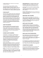
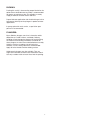
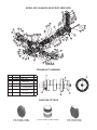
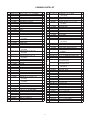
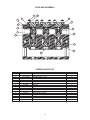
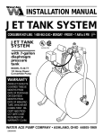
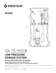
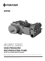
HPL/HPLT SERIES HIGH PRESSURE RECIPROCATING PUMP INSTALLATION AND SERVICE MANUAL NOTE! To the installer: Please make sure you provide this manual to the owner of the equipment or to the responsible party who maintains the system. Part #23833A169 | © 2015 Pentair Ltd. | 07/13/15 GENERAL INSTRUCTIONS: discharge line to the atmosphere at the lowest point in discharge piping. If there are several low points in the discharge line, drain individually. Drain the bypass line by disconnecting or removing plug. If pump has valve lifters, turn hand wheel to unseat valves to prevent frost. If no valve lifters are present, open piping lines to the atmosphere and run pump 15 seconds. Make sure pump does not run longer as this can ruin the packing. Electrical power or engine must be shut off completely before attempting service on the pump or its drive. Air surrounding the unit is to be free of toxic, flammable, or explosive gases. A properly placed and sized relief valve installed in the pump discharge system is necessary for protection and to avoid dangerous overpressure. The relief valve set pressure should not be more than 25% above the design operating pressure and should discharge to the tank or to the atmosphere toward the ground. It must not be directed back to the pump suction system. SERVICE: Lubrication: Fill the crankcase with synthetic 80W140 gear oil with API classification GL-5 (SAE J2360). When first operating the pump, change the oil and filters after the first 30 hours of run time, then every 300 hours or once a year. Maintain oil level at the half way point on the oil level sight glass, approximately 8.5 gallons. Check oil level daily and add oil as needed. Use spin-on water-absorbing filter; WATERGUARD® and inline oil filter; FLOW EZY FILTERS® replacement element. CAUTION: All pumps should be installed level. For mobile applications the maximum angle of intermittent operation should be no more than 5° in any one direction. Improper installation or use could result in loss of life. CALIFORNIA PROPOSITION 65 WARNING: GUIDED VALVES WITH URETHANE/ *FLUORELASTOMER SEAL: This product and related accessories contain chemicals known to the State of California to cause cancer, birth defects or other reproductive harm. * Seal for HPLT Pumps These valves permit quick, easy and safe methods of installing and removing the whole valve. The new system allows servicing without distortion of the seat, no damage to the fluid end and no special tools are needed. Guided valves do not have any tapered seats so the installation and removal of the valves are extremely less complicated and destructive to the fluid end. STARTING THE PUMP: Fill pump crankcase with recommended oil to the half way point on the oil level sight glass, approximately 8.5 gallons. Replace all drain plugs in the pump and piping. Inspect tank to be sure that no foreign material is in the tank or suction line. Fill tank at least half full. Avoid prolonged dry operation which may cause excessive wear on plunger packing. Be sure that an operating pressure gauge is located in the discharge line. Use a heavy duty, liquid filled, pulsation free pressure gauge. Make sure all valves, including the spray gun or nozzles, are open in discharge line and completely back off pressure adjusting device on pressure regulating valves. Check pressure rating for pulsation dampener pressure regulator and pipe fitting to make sure working pressure is not over the maximum pressure rating. The valves are made to sit on top of one another and work together, therefore, there are no threads for the valves to screw into. The use of a puller might be needed. Before installing, thoroughly clean all surfaces using a cleaning solvent. Installation will be through the top of the fluid end. For the suction valve, drop down these parts in the following order; O-ring, valve casting/cage, valve, spring and then washer. After starting, close the discharge valve or spray gun slowly while watching pressure gauge to make sure relief valve or unloader is operating properly. Adjust relief valve or unloader to desired pressure. Cycle nozzles, or gun, on and off to be sure that pressure adjustment and regulator operation is satisfactory. Nozzle capacity should not exceed 90% of pump capacity for satisfactory regulator operation. Avoid freezing by draining all water from the pump and system in cold weather. Repeat this same process for the discharge valve. To complete, the washer that is on top of the discharge valve needs to be placed concave side down. Slide the valve cover over the four designated studs and tighten the bolts. BEARING HALVES/CONNECTING RODS/CROSSHEADS: INSTRUCTIONS FOR DRAINING PUMP IN FREEZING WEATHER: The connecting rod assemblies employ precision automotive type steel, backed with Babbitt-lined crankpin bearing halves, which require no shims for Open suction line to the atmosphere at lowest point in suction piping and remove suction pipe plug. Open 2 clearance adjustment. This pump employs full circle crossheads and hardened stainless steel extension rods, which are field replaceable. Check that all oil holes are clean and fully open. All surfaces must be perfectly clean and lightly oiled prior to assembly. Remove any burrs or sharp corners which may prevent the fitting of bearings. Extension rods are provided with wrenching flats to permit tightening of the tapered thread into the crosshead, establishing accurate alignment. HPL pumps utilize high strength cap bolts suitable for initial loadings, maintained by hardened spring lock washers. After all rods and caps are secured, slowly turn the crankshaft to be sure bearings do not bind. Before beginning the assembly, all parts must be cleaned, removing all oil, dirt, rust and foreign matter which prevent proper fitting or scoring of the rubbing surfaces. Clean and examine the power frame bores for scoring and normal wear, especially the lower crosshead guide way. Examine the location of each connecting rod within its crosshead to verify it does not touch the crosshead boss or skirt. CRANKSHAFT ASSEMBLY: Frame bores which have become worn must be sleeved with a cast iron liner to re-establish correct geometry and alignment. The HPL120-30/HPL120-30T crankshaft suspension utilizes a double row bearing and a single row bearing. The crankshaft already has the correct running clearance, so there is no need for shimming. Installing Wrist Pin Bushings: The wrist pin bushing is a precision machined bearing bronze which is press fitted into the eye of the connecting rod. Thorough cleaning with solvent of all components prior to assembly is essential. Remove any oil, dirt, rust and foreign matter which might prevent interference. Crankshaft journals are critical. Remove all burrs, rust spots, and nicks, paying special attention to the ground areas on which bearings and oil seals operate. Carefully align the bushing with its hole and after applying oil to bushing O.D., use a hydraulic press to force it home. When a bronze bushing is pressed into place, the I.D. of the bushing is reduced somewhat, owing to the extent of press fit. A new wrist pin should be inserted into the bushing bore to establish that the running clearance has been obtained. PINNING THE CROSSHEAD: Crankshaft Roller Bearings: Shaft and frame tolerances provide a tight fit on the shaft. Heat the retaining plate and inner race bearing assembly and promptly drop them onto the shaft. The inner race must contact the seat thrust face. Do not hammer on the bearing assembly as the soft steel cage is easily distorted. If the inner race does not contact its thrust face properly, it must be pressed into place using a specially machined sleeve (being cautious not to touch the soft steel cage). A press fit between the crosshead pin and crosshead is used to secure the pin against any motion. A hydraulic press forces the pin through the bosses of the crosshead. Retainer Plate Installation: Retainer plates are shrink-fitted onto the shaft. The retainer plate for the large bearing is placed on top of the bearing. After installing the pin, carefully check the crosshead O.D. to see if it is out-of-round. The crosshead O.D. must be restored into its original roundness. Once the plate is correctly positioned, screw in the retainer. This will keep the inner race of the bearing in place. Precision Crankpin (Crankthrow) Bearings: Myers® pump crankpin bearings require no shimming to establish correct running clearance due to precise machining of the connecting rod, caps and crankpin journals. The double row bearing and its retainer plate is on the drive side of the crankshaft. The retainer plate is placed onto the crankshaft and once cooled, the double row bearing is dropped on top of the retainer. This retainer will be screwed in through the actual power end of the pump. Replacement bushings are furnished pre-bored, eliminating the need to ream the installed bushing bore. If interference is present, lightly hone the bore of the bronze but do not reduce the pin size. The bore of the bushing must be round and free of taper. Crankpins which are worn out-of-round, tapered or badly scored should be discarded. Connecting rod cap bore must be perfectly round and within tolerance. Discard if elliptical or tapered as the result of abnormal heating. Each cap and rod is matchmarked for correct identification. Disassembly: After removing the connecting rod cap and cap bolts, remove the bearing carrier from the frame. Support the shaft during removal to avoid damage. The crankshaft may be extracted once all connecting rods are moved clear. Examine the crankpin surfaces for wear or corrosive pitting. 3 Spring-Guide Ring: It is important to obtain a wellfitted guide ring to carry the weight of the plunger. Discard any guide rings which become worn or scored. Apply oil to this ring when fitting in the box. If worn more than .010" undersize, the crankshaft should be replaced. Crankshaft roller bearings should be carefully examined for pitting, scoring or corrosion, and replaced as required. The roller assembly is removed by cutting away the cage and heating the inner race while holding the shaft vertically. Avoid excessive heat on the crankshaft as this tends to distort its geometry. Gland Ring: This ring also fits the plunger and helps support the plunger weight. Discard if the bore is worn, rough or out-of-round. Lightly oil the ring before insertion. Spring Loaded Packing: Three rings of compression packing are installed with the intersections 180º apart to discourage leaking. PINION SHAFT: The pinion shaft is the drive shaft. It has a helical gear that turns the large gear connected to the end of the crankshaft. The bearings and spacers are all shrinkfitted to the pinion shaft. The retaining plate for the bearing is screwed into the end of the pinion shaft. When removing the pinion shaft, do not lie it down or pivot it too far in any direction as the bearing on the end will come apart. Once the gear cover is removed, the large gear can be disassembled and removed. Unscrew the retaining plate covering the bearing on the pinion shaft end and remove the pinion shaft to perform maintenance. INSERTING THE PLUNGER: Apply oil liberally to the plunger O.D. and to each extension rod O.D. before lightly tapping it through the packing and the stuffing boxes. This will assist with installation through the wiper box seals. A soft rubber mallet is recommended to avoid any damage to the plunger face or its threads. INSTALLING THE GLAND: HEAT EXCHANGER: The heat exchanger consists of two plates on the back of the power end. The first plate is mounted directly against the back end of the pump and the smaller plate is mounted against the first plate. This two-piece set-up allows the oil that is inside the pump to transfer heat to the water running through the heat exchanger. Considerable downward pressure on the gland is required to compress the spring, move packing into location, and start the threads of the box. The packing rings and plunger surfaces are fragile and damage easily. Once the gland threads are started, screw down completely until it is tight against the face of the box for spring loaded packing. For Hi/Lo, J-Style or Gland adjusted packing, tighten the gland until it is seated firmly against the packing. PACKING AND PLUNGERS: INSTALLING THE STUFFING BOX: Stuffing boxes, with plungers separable from the extension rods, are field replaceable. The boxes, plungers and packing units may be installed as a unit assembly. All boxes are retained by four studs and nuts, centered in the frame bore, securing correct alignment. The plungers may also be removed separately to simplify repacking. Remove the extension rod to acquire the space required to remove the plunger. The stuffing boxes are aligned from the bores of the power frame and the faces of the fluid end. These surfaces must be cleaned of rust, scale and dirt before assembly. A nitrile rubber seal is used between the face of the fluid end and the face of the box. Replace if damaged. All stuffing boxes are retained by four large studs and nuts extending through the power end to clamp the box and the power frame tightly against the fluid end face. These four stud nuts must be evenly tightened. Spring Loaded Packing: The gland is screwed tightly onto the box and contacts the face. No adjustment is provided by the gland. The spring provides all the initial compression and adjustment. The force exerted by the spring is subject to the space provided, making it important the ring length is correct for proper tension. CONNECTING PLUNGER: To install the metal baffle plate on the extension rod, roll the pump slowly until the extension rod male threads just touch the mating plunger female threads and tighten the connection. Do not use a “cheater” when connecting the plunger to extension rod. Spring: A stiff spring, closely fitting the bore of the stuffing box is used in this assembly. It is compressed to the operating length plus 0.25" and tied with waxed nylon cord. Each spring is assembled into the stuffing box without contacting the plunger. 4 PACKING: Packing life usually is increased by proper lubrication. An optional force feed lubricator assembly is recommended for pumps on continuous duty. This provides a steady supply of lubricant to lower friction and heat. Proper lubricator application aids the dissolving of salt to help prevent build up on the plungers in produced water applications. In pumps placed in arctic service, a special low pour point oil is recommended. PLUNGERS: Myers Rokide® plungers consist of a chromium-oxide deposition on a solid stainless steel body. Ordinary handling will not damage the plunger, but avoid striking the coated surface during installation. All threads on these plungers must be clean and oiled before assembly. Stainless steel has a tendency to gall and seize, therefore, an anti-seizing lubricant is recommended. Apply oil to the threads and the rubbing surface. Solid ceramic plungers are also available. They are fragile and vulnerable to thermal and mechanical shock. Use only a rubber mallet to insert these into the packing. 5 THE PUMP MUST BE INSTALLED WITH A PRESSURE RELIEF VALVE IN DISCHARGE LINE TROUBLESHOOTING Pump fails to build pressure with discharge closed Failure to hold pressure with discharge open Pump is noisy Pump gets hot Pressure gauge shows abnormal fluctuation POSSIBLE CAUSE OF PROBLEM 1. Pump not primed 2. Valve closed in suction line X 3. Suction line or sediment chamber clogged X X 4. Air leak in suction line X X 5. Pressure regulator valve badly worn or not properly adjusted X 6. Broken valves or springs X X X 7. Pump packing or valves badly worn X X X 8. Pressure regulator bypassed by open #1 valve X 9. Pump cylinder body cracked X X 10. Water in crankcase X 11. Worn connecting link inserts or wrist pin bushings X X 12. Lack of oil in crankcase X X 13. Foaming mixture in tank X X X 14. Regulator plunger sticking X 15. Foreign matter under pump valve X X X 16. Loose plunger rod X 17. Improper preload of crankshaft bearings X X X X X X X X X Explanation of the Service Chart 1. Pump priming is usually not necessary when the pump is installed correctly. However, there are certain conditions which may make it necessary to prime the pump to get the pumping action started. Priming will be required when it is impossible for the piston to displace the air in the pump and replace it with water. This could be caused by a high suction lift, the valves being stuck on the seat or by valves sticking due to extreme corrosion. A pump will not prime readily if someone has tampered with the valve springs causing them to exert undue pressure of the valve plates against the valve seats. 3. A sediment chamber should be installed in the suction line between the gate valve and the pump suction. The strainers in these sediment chambers are to allow a free flow of liquid to the pump. If the strainers become severely clogged, they will completely stop the flow of liquid to the pump. 4. Any piston pump operating at a high pressure will not perform properly or quietly if a mixture of air and water is allowed to enter the pump suction. A small air leak in the suction line will cause the pump to knock and vibrate excessively by allowing the pump to draw a certain amount of water mixed with air on each stroke of the piston. A large air leak will cause the pump to lose prime after which it cannot be reprimed until the air leak is stopped. Air leaks may occur at the joints of the suction line piping, at the gate valve in the suction line, at the gasket sealing the cap on the sediment chamber, by a crack in the suction wall of the cylinder body, or by air drawing past the packing on the suction stroke if the packing is badly worn. 2. A gate valve is sometimes installed in the suction line between a tank or pressure line and the pump sediment chamber. It will shut off the supply source in order to clean the sediment chamber or to perform pump repairs. If this valve is partially or fully closed, it will interfere with the flow of water to the pump suction. This also may cause severe knocking and vibration of the pump because the water cannot flow into the cylinder cavities fast enough. 6 5. If the pressure regulator internal bypass valve is worn, it will allow too much of the pump capacity to be bypassed and recirculated back to the tank. By examining the flow from this valve with the discharge turned on, it can be determined whether or not the valve is worn. If a heavy flow continues when the discharge is turned on, it is usually a good indication of a worn valve and should be replaced. 11.Worn connecting link bearings are caused by unusual or adverse operating conditions and are seriously affected by corrosion if water is present in the crankcase. They will wear out from overheating if the oil is not high quality or clean. Drain, clean and refill with new oil at the specified interval and prior to any storage period. Replace link inserts as soon as any wear is noticed to avoid damage to crankshaft journals. 6. A broken pump valve or spring will often prevent one cylinder from functioning properly resulting in a rough pulsing discharge, a knocking sound and a loss of capacity. If not repaired immediately, the rough running pump can cause mechanical damage to itself or other system components. 12.Low oil in the crankcase can quickly cause failure of the pumps power end and result in extensive repairs. Oil level should be checked periodically during normal operation and during all maintenance work. 13.A foaming mixture will sometimes have the same effect as a small air leak in the suction line. This is because various quantities of the foam are drawn through the suction line into the pump disrupting the normal flow of water. 7. Worn packing, valves or valve seats will cause a severe drop in pump capacity pressure. Worn packing is detected by water leakage and should be replaced immediately. Water getting in the pump crankcase will cause severe corrosion of the bearings and cause rapid wear. Worn valves can be detected by visual examination of each valve assembly. Abrasive liquid will cause wire cuts which begin as a very small groove, but increases rapidly once the valve starts to leak through this groove. If the valves are replaced as soon as they start to show this cutting action, it will prevent the valve seat from becoming cut in a similar manner. 14.Pressure regulators can become sluggish due to the plunger sticking or fitting too tightly in the cylinder. This may happen by an accumulation of chemicals collecting in and around the plunger or from excessive corrosion of the plunger parts. To check this condition, remove and clean the plunger and cover the parts with a waterproof grease before assembling. The pressure regulator may chatter or vibrate excessively due to an unstable operation from nozzling in the high or low capacity range of the regulator. The range should be at least 50% to 90% of pump capacity. 8. If a portion of the pump delivery is allowed to bypass because the #1 control valve is not completely closed, there may not be adequate flow to develop full pressure. This will cause rapid wear in the control valve. Any excess flow should be bypassed only by the pressure regulator. 15.If foreign matter becomes lodged between the pump valve and valve seat, a drastic drop in capacity and considerable surge or pulsation will occur in the discharge line. Examine each valve if this occurs. 9. Pump cylinder bodies withstand an extreme amount of shock and pulsation while in operation. If the pump is allowed to freeze, by not being drained, the freezing may crack the cylinder body walls in almost any location. If the crack occurs on the suction valve or cylinder portion of the body, it may allow a small amount of air to enter on the suction stroke and cause noisy operation or a decrease in pumping capacity. If the crack develops in the walls between the cylinder cavities or discharge valve cavity, it may allow the water to flow from one cavity to the adjacent cavity and cause uneven displacement. 16.Noisy pump operation may be caused by a loose plunger rod in the crosshead. This noise usually has a regular cadence timed with each stroke. If this happens, always replace both the rod and the crosshead. 17.Increased preload to the crankshaft bearings will reduce bearing life, require more power and generate more heat. Insufficient preload may cause a knock, timed with the crankshaft rotation. Check for loose bolts on the crankshaft end caps or adjust shims to obtain proper bearing preload. Worn roller bearings will continue to run but will introduce wear particles into the oil. 10. Water may accumulate in the pump crankcase from two sources; leakage of packing or an accumulation of condensation/moisture inside the crankcase due to changes in weather or the repeated heating and cooling of the pump. Pumps used consistently, running for a considerable period of time to heat the oil and other working parts, will not normally accumulate water by condensation. Replace the packing as soon as it starts to leak. 7 MODEL HPL120-30/HPL120-30T EXPLODED VIEW 74 74 74 74 74 74 74 74 74 41 44 43 52 51 45 71 74 74 74 74 74 50 47 72 48 53 54 42 2 11 9 8 12 62 83 82 55 56 84 85 74 49 3 15 51 16 75 4 76 77 73 1 19 17 18 23 21 37 7 61 86 6 34 5 26 67 80 2 40 65 70 87 79 57 78 24 81 88 60 58 59 90 62 20 27 39 69 66 63 22 94 69 64 34 35 91 51 36 34 29 30 31 32 CRANKSHAFT ASSEMBLY Item A B C Eng. No. 27723D000 27730A000 27731A000 D E 072320673 27729B000 F 000110141 G 06106A043 Description CRANKSHAFT BEARING, LARGE BEARING, MEDIUM, DOUBLE ROW PLATE-RETAINING RETAINER-BEARING, ALUMINUM BRONZE SCREW-SET(HEX SOC) 1/4-28 x 1/2 SCREW, CAP SKT HD SST 1/4-28 UNF x 7/8 LG D Qty. 1 1 1 F E G 1 1 6 6 C A B FLUID END FITTINGS BLANK; DISCHARGE (27919A001) 2.5" NPT; DISCHARGE (27919A002) 4" NPT TO 4" ID HOSE; SUCTION (27918A003) 8 BLANK; SUCTION (27918A001) 4" NPT; SUCTION (27918A002) COMMON PARTS LIST Item 1 2 3 4 5 6 7 8 9 10 11 12 13 14 15 Eng. No. 100-058112-273 7204-0306-00C 145-200300-999 145-200234-999 7204-0005-00A 27710D001 27756A001 05454A015 19101A009 19101A012 27734A000 27727C001 27740A001 27712D000 19103A039 16 17 18 19 20 21 27740A000 27771A001 27762B000 27728D000 27723D001 029210081 22 100-038234-273 23 24 27717C000 100-038112-273 25 26 27 28 29 30 31 32 33 34 35 36 001560321 7204-0073-10B 27737A000 27714C000 27744A000 7509-0073-00A 27741A000 100-038212-454 154-038068-999 7509-0078-00A 7509-0049-06B 19103A068 37 029210091 38 39 40 41 42 43 7509-0048-00A 05454A014 7204-0309-00C 144670011 27746B000 27720B000 27721B001 27721B003 7204-0054-00A 001500421 130-114012-243 44 45 46 47 Description Qty. H BOLT 5/8-11UNC x 1.5 x 1.5 (30# TORQUE) 6 BOX, WIPER 3 SEAL, WIPER, DOUBLE-LIP CANNED 3 SEAL, WIPER, DOUBLE-LIP 3 PIN, WRIST 3 FRAME-POWER, F120-30 RECIP 1 PIN-DOWEL, BEARING TO POWER FRAME 4 WASHER; LOCK SST 3/8 TYPE 316 SST 9 SCREW; CAP HEX ST PL 3/8-16 x 1 (20# TORQUE) 6 SCREW; CAP HEX ST PL 3/8-24 x 1 (20# TORQUE) 3 SEAL-OIL 1 PINION SHAFT ASSEMBLY 1 PLATE-RETAINING, PINION SHAFT 1 HOUSING-BEARING 1 SCREW; CAP HEX ST Z&D 1/2-20UNF x 1-3/4" LG 3 (75# TORQUE) PLATE-RETAINING, CRANKSHAFT 1 KEY 7/8" SQ. x 2-1/2" LG. 1 RETAINING SPACER 1 GEAR, HELICAL 1 CRANKSHAFT ASSEMBLY 1 SCREW-CAP (FL HD SOC) 1/2-13 x 3-1/2" SST 4 (75# TORQUE) SCREW, CAP, HEX HD, 3/8" NC x 2-3/4 14 (20# TORQUE) ROD-CONNECTING ASSY 3 SCREW, CAP, HEX HD 3/8" NC x 1-1/2 23 (20# TORQUE) WASHER-FLAT 3/8" SST 37 BEARING, CRANKPIN HALF 6 GASKET-SIDE COVER 1 SIDE COVER 1 OIL FILTER 1 NIPPLE FITTING 1/2" NPT x 3/4" NPT 1 OIL PUMP 1 HF BOLT 3/8-16UNC x 2.50 x 1 (20# TORQUE) 6 SPRING, LOCKWASHER; 3/8" 6 TUBE FITTING 1/2" NPT x 1/2" HOSE 4 1/2" x 6" SST BRAIDED HOSE W/BRASS ENDS 1 SCREW; CAP HEX ST 1/2-13UNC x 1-1/2" 6 (75# TORQUE) SCREW-CAP (FL HD SOC) 1/2-13 x 1/2" SST 12 (75# TORQUE) WATER GUARD FILTER 1 WASHER; LOCK SST 5/16 2 CROSSHEAD 3 SCREW, CAP 7/8-14 (HEX SOC HD) (400# TORQUE) 4 TIE ROD 1-1/4"-12 (TPI) (400# TORQUE) 2 ROD-EXTENSION 3 PLUNGER, HPL120-30/HPL120-30T 3 PLUNGER, HPL170-20/HPL170-20T 3 SEAL, STUFFING BOX; NITRILE RUBBER 3 O-RING 1/8 x 5.359 ID #2-253 3 JAM NUT, HEX (STEEL); 1-1/4"-12 (600# TORQUE) 2 Item 48 49 50 51 52 53 54 55 56 57 58 59 60 61 62 63 64 65 66 67 68 69 70 71 72 73 74 75 76 77 78 79 80 81 82 83 84 85 86 87 88 89 90 91 92 93 94 9 Eng. No. Description 133-114012-243 NUT, HEAVY HEX; 1-1/4"-12 THREAD (1100# TORQUE) 27709D001 FRAME-TRANSITION 7507-2791-00 STUD, STUFFING BOX; 1" x 4-7/8" (200# TORQUE) 05454A016 WASHER; LOCK SST 1/2 TYPE 316 SST 005680061 SCREW-CAP (HEX SOC) 1/2-13 x 1-1/2 SST (75# TORQUE) 27713D000 HOUSING-GEAR COVER 27736B000 GASKET-GEAR COVER 7509-0085-00A TUBE FITTING 1/4" HOSE x 3/8 NPT 05004A123 BUSHING; PIPE 3/8MPT x 1/8FPT 27725D000 HEAT EXCHANGER COVER 27726B000 GASKET-HEAT EXCHANGER COVER 27724D000 HEAT EXCHANGER 27726B001 GASKET-HEAT EXCHANGER 7509-0084-00A TUBE FITTING 1/2" HOSE x 3/8" NPT 029210011 SCREW-CAP (FL HD SOC) 1/2-13 x 1-1/4" SST (120# TORQUE) 19100A004 SCREW; CAP HEX 5/16 SST 3/4 (11# TORQUE) 7509-0047-00A WATER GUARD FILTER HEAD 05454A023 WASHER; LOCK SST 1/4 TYPE SST 27745A000 SUPPORT BRACKET, WATER GUARD FILTER 19099A003 SCREW; CAP HEX 1/4-20UNC SST 1/2 LG (6# TORQUE) 27756A002 PIN-DOWEL, TRANSITION TO POWER FRAME 7509-0072-00A TUBE FITTING 1/2" HOSE x 3/4" NPT 7509-0049-38B 1/2" x 38" SST BRAIDED HOSE W/BRASS ENDS 7204-0016-00A DISC-DEFLECTOR 27796B000 STUFFING BOX/PACKING ASSEMBLY, HPL120-30/HPL120-30T 27796B030 STUFFING BOX/PACKING ASSEMBLY, HPL170-20/HPL170-20T 127-100008-243 SCREW; CAP HEX 1/4-20UNC SST 1/2 LG (400# TORQUE) 27711D001 FLUID END ASSEMBLY 05030A264 FLAT WASHER, SPECIAL 13015A005 VALVE PUSHER ASSEMBLY 03210A000 PIPE PLUG 3" NPT 05010A005 ELBOW; STREET, GALV 1-1/2" 05004A027 1-1/2 x 1-1/4 BUSHING 7602-3001-00A FILTER; BREATHER 05022A064 PIPE PLUG 1" NPT 27764B000 OIL DISTRIBUTION MANIFOLD 170-038003-237 PIPE PLUG 3/8" NPT 7203-0100-15A HOSE, TEFLON; 1/4", 304SS BRAIDED 246-014018-220 ELBOW; 1/8" NPT x 1/4" JIC 170-014002-405 PLUG-PIPE 1/4" NPT 7602-3000-00A GAUGE-OIL LEVEL 149680021 PIPE 1/4" x 2" GALV. TUBE 067130223 PUMP FOOT 067130213 PUMP FOOT 7509-0049-18A HOSE, BRAIDED; 1/2" x 18" LONG 05126A063 TEE, PIPE; 1" NPT x 1" NPT x 3/4 05427A250 PIPE; 1 x 3-1/2" TBE. 40 GALVST 14443A001 1.5" DIA. 0-30 PSI GAUGE Qty. 2 1 12 21 12 1 1 3 3 1 1 1 1 1 20 2 1 2 1 2 2 3 1 3 3 3 12 1 2 3 1 1 1 1 2 1 4 3 3 1 1 1 2 2 1 1 1 1 FLUID END ASSEMBLY 3 1 4 14 2 12 13 5 7 9 10 8 11 10 6 COMMON PARTS LIST Item 1 2 3 4 5 6 7 8 9 * 10 * 11 12 13 14 * Eng. No. 27711D000 27718B000 7507-2793-00A 133-100008-243 27719B000 170-014002-405 27715B000 27716B000 7201-0751-00A 7201-0751-01A 05876A050 05876A266 27760A001 27760A003 27761A000 05876A035 05876A267 Description FLUID END VALVE COVER STUD,COVER; VALVE 1" X 3-3/4" NUT, HVY. HEX; 1"-8 THRD, STEEL, AS VALVE GUIDE 1/4" NPT PIPE PLUG VALVE VALVE SEAT A-50 TRIPLEX PUMP POLYURETHANE INSERT A-50 TRIPLEX PUMP FLUORELASTOMER INSERT O-RING; 3-1/8" x 2-7/8" x 1/8" (#2-233) O-RING; 3-1/8" x 2-7/8" x 1/8" (#2-233) SPRING-SUCTION, LEFT HAND SPRING-DISCHARGE, RIGHT HAND WASHER-SPRING O-RING: 3-1/4" x 3" x 1/8" (#2-234) O-RING; 3-1/4" x 3" x 1/8" (#2-234) *PARTS FOR HPLT PUMPS ONLY. 10 Qty. 1 3 12 12 6 3 6 6 6 6 6 6 3 3 3 3 3 THIS PAGE INTENTIONALLY LEFT BLANK 11 STANDARD LIMITED WARRANTY CENTRIFUGAL & RECIPROCATING PUMPS Pentair Myers® warrants its products against defects in material and workmanship for a period of 12 months from the date of shipment from Pentair Myers or 18 months from the manufacturing date, whichever occurs first – provided that such products are used in compliance with the requirements of the Pentair Myers catalog and technical manuals. During the warranty period and subject to the conditions set forth, Pentair Myers, at its discretion, will repair or replace to the original user, the parts that prove defective in materials and workmanship. Pentair Myers reserves the right to change or improve its products or any portions thereof without being obligated to provide such a change or improvement for prior sold and/or shipped units. Seals, piston cups, packing, plungers, liners and valves used for handling clear, fresh, nonaerated water at a temperature not exceeding 120ºF are warranted for ninety days from date of shipment. All other applications are subject to a thirty day warranty. Accessories such as motors, engines and auxiliary equipment are warranted by the respective manufacturer and are excluded in this standard warranty. Under no circumstance will Pentair Myers be responsible for the cost of field labor, travel expenses, rented equipment, removal/reinstallation costs or freight expenses to and from the factory or an authorized Pentair Myers service facility. This limited warranty will not apply: (a) to defects or malfunctions resulting from failure to properly install, operate or maintain the unit in accordance with the printed instructions provided; (b) to failures resulting from abuse, accident or negligence; (c) to normal maintenance services and parts used in connection with such service; (d) to units that are not installed in accordance with applicable local codes, ordinances and good trade practices; (e) if the unit is moved from its original installation location; (f) if unit is used for purposes other than for what it is designed and manufactured; (g) to any unit that has been repaired or altered by anyone other than Pentair Myers or an authorized Pentair Myers service provider; (h) to any unit that has been repaired using non factory specified/OEM parts. Warranty Exclusions: PENTAIR MYERS MAKES NO EXPRESS OR IMPLIED WARRANTIES THAT EXTEND BEYOND THE DESCRIPTION ON THE FACE HEREOF. PENTAIR MYERS SPECIFICALLY DISCLAIMS THE IMPLIED WARRANTIES OF MERCHANTABILITY AND FITNESS FOR ANY PARTICULAR PURPOSE. Liability Limitation: IN NO EVENT SHALL PENTAIR MYERS BE LIABLE OR RESPONSIBLE FOR CONSEQUENTIAL, INCIDENTAL OR SPECIAL DAMAGES RESULTING FROM OR RELATED IN ANY MANNER TO ANY PENTAIR MYERS PRODUCT OR PARTS THEREOF. PERSONAL INJURY AND/OR PROPERTY DAMAGE MAY RESULT FROM IMPROPER INSTALLATION. PENTAIR MYERS DISCLAIMS ALL LIABILITY, INCLUDING LIABILITY UNDER THIS WARRANTY, FOR IMPROPER INSTALLATION. PENTAIR MYERS RECOMMENDS INSTALLATION BY PROFESSIONALS. Some states do not permit some or all of the above warranty limitations or the exclusion or limitation of incidental or consequential damages and therefore such limitations may not apply to you. No warranties or representations at any time made by any representatives of Pentair Myers shall vary or expand the provision hereof. 1101 MYERS PARKWAY ASHLAND, OHIO, USA 44805 419-289-1144 WWW.FEMYERS.COM Warranty Rev. 12/13