1
DGF12 System
Low Pressure Sewage System
Installation and Service Manual
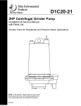
For use with the following Delta grinder pumps:
• D1P20 (shown on cover)
• D1C20
• D2C20
NOTE! To the installer: Please make sure you
provide this manual to the owner of the pumping equipment or to the responsible party who
maintains the system.
05625-459-1
1
GENERAL INFORMATION
Thank you for purchasing your Low Pressure Sewer
Basin System.
DANGER
Risk of fire or explosion. Do not smoke or use open
flames in or around this system. This system is not
intended for use in hazardous locations per NFPA 70
National Electric Code. Consult factory for optional
equipment rated for this use.
Before Installation:
This manual contains important information for the
safe use of this product. Read this manual completely
and follow the instructions carefully. Reasonable
care and safe methods relating to the installation and
operation of this product should be practiced. Check
local codes and requirements before installation.
DANGER
Cutting Risk. Risk of serious cutting or amputation
exists. Disconnect all power sources prior to servicing
pump or grinding mechanism. Pump may start without
warning. Grinding mechanism is extremely sharp.
Use caution when handling grinder mechanism.
DANGER
Risk of electrical shock or electrocution. May
result in serious injury or death or fire hazard. Installer
must disconnect all electrical sources prior to installation. Only qualified personnel may install this system.
NFPA 70/National Electric Code (NEC) or local codes
must be followed. System must be properly grounded
according to NEC.
DO NOT THROW AWAY OR LOSE THIS MANUAL.
Keep it in a safe place so that you may refer to it often
for the continued safe operation of the product.
DANGER
CAUTION
Biohazard Risk. Once wastewater source has
been connected to system, Biohazard Risk exists.
Installer(s) and/or service personnel must use proper
Personal Protective Equipment and follow handling
procedures per OSHA 29 CFR 1910.1030 when
handling equipment after wastewater source has been
connected to system.
Delta Environmental Products does not recommend
basins with base / bottom diameters greater than 30"
when installing a simplex positive displacement pump
(D1P20) system. When operational conditions require
a basin with base/bottom diameter of greater than 30"
it is necessary to perform a sludge pump out on the
basin at least once per year to prevent any potential
septic/odor conditions.
INSTALLATION SKILL REQUIREMENTS
These instructions are meant only to be an installation
guide; therefore, unusual installation conditions not
covered in these instructions require experienced
personnel capable of utilizing reasonable engineering
principles for the installation and operation of the system.
The installation of a basin system is a specialized skill,
which requires individuals with the basic understanding
of excavating, pipe fitting, and electrical wiring.
EXCAVATION INSTRUCTIONS
DANGER
Excavation Location
Excavation location shall be made according to
local codes and regulations. Check with local utility
companies for the location of underground utilities
prior to excavation. Care should be taken to avoid
buried utility lines, piping, and other buried structures
and foundations. Failure to follow these instructions
may result in serious personal injury or death.
Excavation for
Basin Systems:
Effect appropriate excavation based on size of the
basin, desired entrance point of the influent line, and
entrance of power connection.
2
05625-459-1
BASIN INSTALLATION INSTRUCTIONS
CAUTION
If the basin is not tied down during installation,
rain or flood conditions may cause the basin to
float upward, causing damage to the basin or
basin connections.
Step 2
Lifting of the basin may be done with a nylon or other
non-damaging type material sling. Do not wrap a chain
or steel cable around the basin as damage may result.
Do not attach lifting mechanism around discharge hub
or electrical hub.
Basin System Handling:
Factory built basin systems must not be dropped,
dragged, rolled, or handled with sharp objects.
Improper handling of basins may result in damage to
the basin, damage to basin components, or leaks in
the piping assemblies.
DANGER
Risk of electrical shock or electrocution. May result
in serious injury or death or fire hazard. Failure to
properly support electrical conduit, lines and
connections may result in structural failure. Electrical
connections may be damaged exposing live electrical
connections.
Step 1
The pad under the basin, requires 4 to 6 inches of
appropriate fill. The ideal basin pad is concrete in
conjunction with anti-flotation tie-down studs. Basin
anti-flotation tie-down kits are available from Delta
Environmental Products. If concrete pad is not used,
the aggregate must be compacted to a minimum
85% standard proctor density per ASTM D698, or
as required by the Authority Having Jurisdiction.
Concrete pad or aggregate surface must be leveled
flat and free of voids to conform to the basin bottom.
Basin bedding depth should be calculated such that
the basin top will protrude 3" above the normal grade
upon final installation.
05625-459-1
Step 3
Lower the basin into excavation, position and level
properly. Mount basin to base anchor bolts if an
anti-flotation tie-down kit is used. If basin is fiberglass,
inspect basin and seal off any cuts or scratches to
prevent fiberglass deterioration.
3
INFLUENT AND DISCHARGE CONNECTION INSTRUCTIONS
Influent and Discharge
Connections for Basins:
Step 1
An inlet grommet is the standard supplied influent
connection device. If another type of inlet hub is used,
refer to the directions included with the hub.
WARNING
Failure to use a properly piloted hole saw may
result in damage to basin which may result in
structural failure or serious leaks.
Step 2
Lubricate inside lip of inlet grommet with pipe soap.
Clean outer end of influent pipe and push pipe through
grommet. Ensure pipe does not protrude inside basin
so as to interfere with pump removal or float operation.
Determine point at which influent line will enter basin
and, using a properly maintained pilotted hole saw
sized per chart below, drill a hole through the basin
wall. If using a fiberglass basin, clean cut hole and
apply a sealant coating to the cut section to prevent
fiberglass deterioration. Insert the inlet grommet into
the drilled hole.
Pipe Size
3"
4"
6"**
Step 3
Close shut-off valve and make discharge line
connection. It is strongly recommended that an
additional shut-off valve and redundant check valve be
located outside the basin at any force main entrances check local codes for specific requirements.
Hole Saw Diameter*
4"
5"
7"
*Contact factory for availability of proper sized hole saw if necessary.
** 6" pipe size requires use of fiberglass basin
BACKFILL INSTRUCTIONS
The Authority Having Jurisdiction has the right to
require alternate materials or procedures for back
filling the installation.
A. Gravel-clean and free flowing with particle size not
less than 1/8" nor more than 3/4" in diameter. Use
this description when ordering or specifying as
material varies upon geographical location. This
material is commonly known as “pea gravel”.
B. Stone or gravel crushings with angular particle size
of not less than 1/8" nor more than 1/2" diameter,
washed and free flowing, is acceptable as an
alternative material.
CAUTION
In freezing conditions the backfill must be dry and
free of ice. Do not use other backfill materials.
Failure to utilize the recommended bed and backfill
materials during the installation of the basin voids
the basin warranty.
Step 2
At least a 4-6 inch wide band of compacted aggregate,
must be placed in successive layers (6" lifts) around
the entire periphery of the basin. Carefully compact
aggregate under all piping and electrical lines. Cover
grade should slope down 3" to the normal surrounding
grade. Care must be taken to prevent damage to any
influent, discharge, or electrical connections made to
the basin.
DANGER
Risk of electrical shock or electrocution.
May result in serious injury or death or fire hazard.
Failure to properly support electrical conduit, lines
and connections may result in structural failure.
Electrical connections may be damaged exposing
live electrical connections
Step 1
Obtain proper backfill material. The backfill material
provides as much as 90% of the basin’s support
under certain stress conditions. The installer must
be positive that correct bed and backfill materials are
utilized per instructions as follows:
4
05625-459-1
FINAL BACKFILL FOR BASIN SYSTEMS
Polyethylene
Fiberglass
05625-459-1
5
INTERNAL BASIN INSTALLATION INSTRUCTIONS
DANGER
Risk of electrical shock or electrocution. May
result in serious injury or death or fire hazard.
Installer must disconnect all electrical sources
prior to installation. Only qualified personnel
may install this system. NFPA 70/National Electric
Code (NEC) or local codes must be followed.
System must be properly grounded according to
NEC or local codes.
Pump Models:
The basin system may employ any 2 HP submersible
grinder pump which utilizes cutter blades to grind
solids into a slurry. Refer to the pump service manual
for the pump when adjusting, dismantling, or repairing
the pump.
Inspection: Check to be sure that all items for your
particular system are included, and that the phase
and voltage on the pump nameplate are correct as
ordered. Codes: All local codes must be observed.
Consult the local inspector(s) before installation to
avoid costly delays or rework.
DANGER
Cutting Risk. Risk of serious cutting or
amputation exists. Disconnect all power sources
prior to handling or servicing pump or grinding
mechanism. Pump may start without warning.
Grinding mechanism is extremely sharp. Use
caution when handling grinder mechanism.
Grinder Pump Attachments:
Step 1
Attach the stainless steel foot bracket to bottom of the
pump with bolts and washers provided.
Unpacking Pump:
Remove pump from carton. When unpacking unit,
check for concealed damage. Claims for damage must
be made at the receiving end through the delivery
carrier. Damage cannot be processed from the factory.
Apply Pipe:
Step 2
Apply thread sealant to pipe threads and screw the
discharge piping assembly into the pump discharge.
Systems Description:
Factory built basin systems are available in 24" and
30" diameter basins with 60" through 156" depths in
one foot increments. In a flex hose system, the pump
is raised and lowered in the basin using rope or chain
attached to pump and lifting handle attached to ball
check valve. A hydraulic sealing diaphragm on ball
check valve allows the pump to be removed without
disconnecting piping.
Step 3
Attach lifting chain, cable or rope as supplied to the
lifting eye bolts.
Application:
These pump systems are designed for pumping
effluent or sewage water with a pH ranging from 5 to
9, specific gravities from 0.9 to 1.1, viscosities ranging
from 28 to 35 S.S.U. and temperatures up to 140°F.
Internal Basin Connections:
Step 1
If the system is supplied with a float bracket, attach
float switches to the float bracket by clamping strain
relief bushings around the float cords, then inserting
and twisting the bushings into the float bracket slots.
DANGER
Risk of fire or explosion. Do not smoke or use
open flames in or around this system. This system
is not intended for use in hazardous locations per
NFPA/70 National Electric Code. Consult factory
for optional equipment rated for this use.
If the system is supplied with a pressure bell control
unit, please refer to the separate manual regarding the
pressure bell control unit
DANGER
Risk of electrical shock or electrocution. May
result in serious injury or death or fire hazard.
To reduce risk of electrical shock, do not connect
conduit to pump.
Step 2
After grinder pump attachments have been made,
lower the pump unit down and ensure the ball check
valve sealing flange aligns and connects properly with
discharge.
6
05625-459-1
INTERNAL BASIN INSTALLATION INSTRUCTIONS
Junction Box Systems:
Step 1
Ensure power source is off or disconnected.
DANGER
Cutting Risk. Risk of serious cutting or
amputation exists. Disconnect all power sources
prior to handling or servicing pump or grinding
mechanism. Pump may start without warning.
Grinding mechanism is extremely sharp. Use
caution when handling grinder mechanism.
Step 2
Push pump power, seal failure/heat sensor, and
float cords through cord grips in the junction box and
tighten. To prevent corrosion or electrical short, plug
any unused holes.
Do not leave pump in basin unless it is placed in
operation. If a pump has been out of service for an
extended period of time, with the power off, rotate
the impeller by turning the radial cutter with a
screwdriver to be sure it rotates freely.
Step 3
Remove junction box cover and make all connections
inside junction box to all incoming control panel wires.
Step 4
It is recommended that the customer furnish and install
a conduit seal outside the basin to prevent surface
water from entering the junction box.
Electrical Connections:
D1C20 & D1P20
230 V, 1 Phase
Black
Common Power Line
White
Main Power Line
Green
Ground
Electrical Connections:
DANGER
Risk of electrical shock or electrocution. May
result in serious injury or death or fire hazard.
Installer must disconnect all electrical sources
prior to installation. Only qualified personnel may
install this system. NFPA 70/National Electric Code
(NEC) or local codes must be followed. System
must be properly grounded according to NEC or
local codes.
NOTE: Failure to utilize a manufacturer approved
control panel voids the pump warranty and guarantee.
D2C20
Green
Red
White
Black
Orange
IMPORTANT: Properly connect the panel
ground wire to a grounding rod. Improper
grounding voids warranty.
Preoperational Grinder Pump Checks:
Step 1
Ensure power source is off or disconnected.
Panel Wiring:
Step 1
Ensure power source is off or disconnected.
Step 2
Remove pump from basin.
Step 3
With power off, turn radial cutter with a screwdriver to
be sure it rotates freely. If necessary to adjust, refer to
pump service manual.
Step 2
Connect pump power, seal failure/ heat sensor,
and float cords to panel terminals per the schematic
provided. All conduits and cables entering the panel
must be sealed off.
Step 4
Stand clear from pump and with power on, check for
proper rotation of pump by turning “H-O-A” switch to
“HAND”momentarily and then “OFF”. The impeller
should turn counterclockwise when viewed from the
suction end.
For single-phase pumps: Check panel wiring to
ensure white, black, and red pump leads are
connected according to the schematic and panel wire
labels. Single phase pumps will only run if connected
one way.
Three-phase pumps: Interchange any two line leads
to the motor inside the panel if the pump rotates in the
wrong direction.
05625-459-1
1 Phase
Ground
Start Power Line
Main Power Line
Common Power Line
Seal Failure
7
PUMP OPERATIONS
Step 1
Run clear water into the basin until motor housing is
covered.
Step 6 (for float control systems only)
Float adjustment for simplex systems: Adjust
floats so that the water level is above the pump motor
housing, and the pump shuts off when the water level
is 2 inches above the pump volute discharge.
Step 2
Open the shut-off valve to the discharge line.
Float adjustment for duplex systems: Adjust
floats so that a pump will start when the water level
is just above the pump motor housing, and pump on
override water level is 5 inches above the pump motor
housing. Adjust pump shut-off so that water level is
within 2 inches above pump volute discharge. Pumps
should alternate starting, between each other, upon
successive pump down cycles. To check override
level, set both “H-O-A” switches to “OFF” position and
allow water to surpass the override level, then set both
“H-O-A” switches to “AUTO” position and both pumps
should start. Turn off one pump and be sure second
pump starts when override level is reached on second
trial. If pumps fail to cycle in this manner, retrace
control float wiring panel.
Step 3
Turn “H-O-A” switch to the “OFF” position and turn on
main breaker.
Step 4
Start the pump by turning the “H-O-A” switch to the
“HAND” position.
Step 5
Check the pump amperage with clamp on ampmeter
on black pump lead. Readings higher than nameplate
indicate clogged pump, miswiring, or improper voltage.
If basin is not being pumped down and amperage
readings are considerably lower than nameplate then
the pump is air locked.
Step 7
Ensure “H-O-A” switch is set to “AUTO” before placing
system into service.
NOTE: Nameplate amperage is rated at the largest
impeller diameter trim. Pumps with cut diameter
impellers will draw slightly fewer amps than nameplate.
If pump is air locked, refer to the troubleshooting
section in this manual.
PUMP TROUBLESHOOTING
Pump Runs But Does Not Pump Down The Basin
With The “H-O-A” Switch On Either Hand Or
Automatic Position.
1. Cutters may be clogged. Amperage higher than
nameplate may indicate this problem.
2. Pump rotation may be reversed (on three-phase
pumps only). Switching any two power leads on
three phase pumps will correct the rotation.
3. Discharge gate valve may be closed. 4. Pump may be air locked. Fill basin approximately
10 inches or more above the ball check valve
assembly. Raise pump assembly so that the ball
check valve disengages the discharge elbow
(approximately 6 inches). Stand clear from the
sump opening to avoid spray and turn pump on for
a brief second to clear trapped air in the volute.
5. Clogging anywhere from cutters to check valve.
This is evident if no water discharged out of the
check valve after raising the pump to disconnect
the sealing flange. Pull pump assembly and check
for cause of clogging.
6. Discharge head may be too high. Check elevation
against design point of pump.
Below is a list of common problems and possible
solutions. Refer to the pump and panel installation
and service manuals for details regarding any
necessary adjusting, dismantling or repair work.
DANGER
Risk of electrical shock or electrocution. May
result in serious injury or death or fire hazard.
Installer must disconnect all electrical sources
prior to installation. Only qualified personnel
may install or service this system. NFPA 70/
National Electric Code (NEC) or local codes must
be followed. System must be properly grounded
according to NEC or local codes.
DANGER
Cutting Risk. Risk of serious cutting or
amputation exists. Disconnect all power sources
prior to handling or servicing pump or grinding
mechanism. Pump may start without warning.
Grinding mechanism is extremely sharp. Use
caution when handling grinder mechanism.
8
05625-459-1
5. Single phase pump may be miss wired to panel.
The white, black, and red pump power leads must
be connected correctly to panel.
7. Clogging beyond the sealing flange. This is evident
if water is discharged through the check valve when
raising the pump to disconnect the sealing flange.
Inspect system basin piping or discharge piping
from basin to locate clogging.
Overload Trips, Is Manually Reset, And Then Trips
Off Again.
1. Cutters may be clogged. It is possible that the pump
stalled during operation, and starting and stopping
cleared the cutters. If resetting the overloads solves
this problem, return the “H-O-A” switch to “AUTO”
and observe operation.
2. Pump motor may have failed.
3. Start component(s) failure for single phase pumps.
Check start capacitor and start relay for failure.
4. Single phase pump may be miss wired to panel.
The white, black, and red pump power leads must
be connected correctly to panel.
Basin Level Is Pumped Down With “H-O-A” On
Switch Hand Position, But Is Not Pumped Down
With “H-O-A” Switch On Automatic Position.
1. Floats are not hanging free in the basin or are
covered with grease. Pump the level down with the
“H-O-A” switch on “HAND”, so that the floats can be
observed. Relocate and clean float(s) as necessary.
2. If this is a new installation and original start-up, the
floats may be miswired into the control panel. If the
on and off floats are reversed, the pump will short
cycle on and off and will not pump the level down.
3. Floats or alternator are malfunctioning. Pull the
floats out of the basin and hang the “OFF” and “ON”
floats from your hand. Turn the “H-O-A” switch to
“AUTO”. Tilt the “OFF” float so that the large end is
above the cord end – nothing should happen. While
keeping the “OFF” float tilted, tilt the “ON” float in
the same manner – the pump should come on.
Suspend the “ON” float again from your hand – the
pump should continue to run. Finally, suspend the
“OFF” float – the pump should stop running. If this
procedure does not cause the pump to operate as
described, either replace the float(s) or replace the
alternator relay if the system is duplex.
Seal Failure Light Comes On.
1. This indication means the lower seal has failed and
has allowed water to enter the lower seal chamber
to make contact with the electrode. Pump must
be scheduled for maintenance. Refer to the pump
installation and service manual for information on
replacing the lower seal.
NOTE: Use twisted shielded cable for seal failure
cable runs in excess of 100 feet.
Pump Run Light Stays On.
1. “H-O-A” switch may be in hand position.
2. Lower float may have failed causing the pump to
continue operating below the “off” level.
3. Pump may be air locked.
4. Cutters may be clogged.
Circuit Breaker Trips When Pump Tries To Start.
1. Short circuit in pump motor.
2. Water may have entered the motor housing through
either worn out mechanical seals or O-rings.
3. Contactor failure for three phase pumps. Check
pump contactor for burnt contacts.
4. Start component(s) failure for single phase pumps.
Check start capacitor and start relay for failure.
05625-459-1
9
TYPICAL INSTALLATIONS
Pump: D1P20
Switch: DFC
Type: Duplex
Pump: D1P20
Switch: DFC
Type: Simplex
10
05625-459-1
TYPICAL INSTALLATIONS
Pump: D1P20
Switch: DPC
Type: Duplex
Pump: D1P20
Switch: DPC
Type: Simplex
05625-459-1
11
SIMPLEX SYSTEM PARTS LIST
No.
1
1
2
2
2
2
2
2
2
2
3
3
4
4
5
6
6
6
6
7
7
7
7
8
9
10
11
12
13
14
15
16
17
17
18 18a 18b 19
Part No.
21936D200
27567A001
23901D301
23901D304
23901D306
23901D308
27570D001
27570D002
27570D003
27570D004
19101A010
19099A033
001560321
05030A138
097813264
085373165
085373015
085373035
085373055
145340083
145340013
145340163
145340173
19109A018
24227B029
24227B030
29019220450
19101A017
19109A018
05454A015
063750635
149130035
129610783
129610913
07947A020 05004A122 149850001 148790001
No. Part No.
Description
Qty.
20
05004A114
Bushing - 1-1/4" x 3/4" PVC
1
21
05008A059
Nipple - 3/4" Close, PVC
1
22
24335A001
4" Inlet Grommet
1
23
23971A012
Rope - Liftout, 15'
1
24
140841001
Hub - Junction Box 2" NPT
1
25
001760081
Cap - Screw
4
26
001120021
Hex - Nut
4
27
131070021
Washer - Sealing
4
28
128705011
Box - Junction Nema 6x
1
29
148870031
Stand - Wire
1
30
002380071
Cap - Screw
1
31
001560321
Washer-Flat
2
32
19109A018
Hex - Nut
1
33
27012B505
Bracket, SST for Pressure Bell 1
33
22470B005
Tree Bracket, SST for Floats
1
34
124330483
Pipe - 2" x 26-1/2"
1
34
124330493
Pipe - 2" x 38-1/2"
1
34
124330503
Pipe - 2" x 50-1/2"
1
34
06986A084
Pipe - 2" x 62-1/2"
1
35
27012B508
Tube - 50' Press.
1
36
27012B300
Pressure Bell
1
21813A300K Float Switches (not shown)
3
14755A002
Float Bushings (not shown)
3
Description
Qty.
Cover - Sump 24" Plastic
1
Cover - Sump 24" Poly
1
Tank - FRP 24" x 60"
1
Tank - FRP 24" x 72"
1
Tank - FRP 24" x 84"
1
Tank - FRP 24" x 96"
1
Tank - Poly 24" x 60"
1
Tank - Poly 24" x 72"
1
Tank - Poly 24" x 84"
1
Tank - Poly 24" x 96"
1
Cap - Screw (plastic)
6
Cap - Screw (poly)
6
Washer - Flat (plastic)
6
Washer - Flat (poly)
6
Brace - Valve Stem
1
Handle - Extension 2'-0" Deep
1
Handle - Extension 3'-0" Deep
1
Handle - Extension 4'-0" Deep
1
Handle - Extension 5'-0" Deep
Handle - 24" Discharge Dep
1
Handle - 36" Discharge Dep
1
Handle - 48" Discharge Dep
1
Handle - 60" Discharge Dep
1
Nut - Jam
1
Hub - Tank Assy. 1-1/4"
1
Plate - Backup
1
Gasket
1
Cap - Screw
4
Hex - Nut
4
Washer - Lock
4
Gate Valve Assembly
1
Discharge Piping Assembly
1
Pipe - 1-1/4" x 23-1/4" SST
1
Pipe - 1-1/4" x 27-5/8" SST
1
Cross – 1-1/4" SST 1
Bushing – 1-1/4" x 1/2" PVC
1
Valve – Relief
1
Valve - Anti-Siphon
1
a
b
NOTE: Typical installation shown;
actual installation may vary
12
05625-459-1
DUPLEX SYSTEM PARTS LIST
No.
1
2
2
2
2
3
4
5
6
6
6
7
7
7
7
8
9
10
11
12
13
14
15
16
17
17
18 18a 18b 19
20
21
22
23
24
25
26
27
28
29
30
Part No.
24951C036
140020601
140020721
140020841
140020961
19101A010
001560321
097813065
085373165
085373015
085373035
145340083
145340013
145340163
145340173
19109A018
24227B026
24227B030
29019220450
19101A017
19109A018
05454A015
063750635
149130035
129610783
129610913
07947A020 05004A122 149850001 148790001
05004A114
05008A059
24335A001
23971A012
140841001
001760081
001120021
131070021
128705011
148870031
002380071
Description
Qty.
Cover-Sump 36" Fiberglass
1
Tank - FRP 36" x 60"
1
Tank - FRP 36" x 72"
1
Tank - FRP 36" x 84"
1
Tank - FRP 36" x 96"
1
Cap-Screw
6
Washer-Flat
6
Brace - Valve Stem
2
Handle - Extension 2'-0" Depth 2
Handle - Extension 3'-0" Depth 2
Handle - Extension 4'-0" Depth 2
Handle - Lifting 24" Disch. Depth 2
Handle - Lifting 36" Disch. Depth 2
Handle - Lifting 48" Disch. Depth 2
Handle - Lifting 60" Disch. Depth 2
Nut - Jam
2
Hub - Tank Assy. 1-1/4"
2
Plate - Backup
2
Gasket
2
Cap-Screw
8
Hex-Nut
8
Washer-Lock
8
Gate Valve Assembly
2
Discharge Piping Assembly
2
Pipe - 1-1/4" x 23-1/4" SST
2
Pipe - 1-1/4" x 27-5/8" SST
2
Cross – 1-1/4" SST 2
Bushing – 1-1/4" x 1/2" PVC
2
Valve – Relief
2
Valve - Anti-Siphon
2
Bushing - 1-1/4" x 3/4" PVC
2
Nipple - 3/4" Close, PVC
2
4" Inlet Grommet
1
Rope - Liftout, 15'
2
Hub - Junction Box 2" NPT
1
Cap - Screw
4
Hex - Nut
4
Washer - Sealing
4
Box - Junction Nema 6x
1
Stand - Wire
2
Cap - Screw
4
No.
31
32
33
33
34
34
34
34
35
36
37
38
Part No.
001560321
19109A018
27012B505
22470B005
124330483
124330493
124330503
06986A084
27012B508
27012B300
143783365
063120011
21813A300K
14755A002
a
Description
Qty.
Washer-Flat
8
Hex - Nut
4
Bracket, SST for Pressure Bell 1
Tree Bracket, SST for Floats
Pipe - 2" x 26-1/2"
1
Pipe - 2" x 38-1/2"
1
Pipe - 2" x 50-1/2"
1
Pipe - 2" x 62-1/2"
1
Tube - 50' Press.
1
Pressure Bell
1
Brace - Support, SST
1
Clamp - Muffler, SST
2
Float Switches (not shown)
4
Float Bushings (not shown)
4
b
NOTE: Typical installation shown;
actual installation may vary
05625-459-1
13
14
05625-459-1
05625-459-1
15
67$1'$5'/,0,7(':$55$17<
'HOWDZDUUDQWVLWVSURGXFWVDJDLQVWGHIHFWVLQPDWHULDODQGZRUNPDQVKLSIRUDSHULRGRIPRQWKVIURPWKHGDWHRI
VKLSPHQW IURP 'HOWD RU PRQWKV IURP WKH PDQXIDFWXULQJ GDWH ZKLFKHYHU RFFXUV ILUVW SURYLGHG WKDW VXFK
SURGXFWV DUH XVHG LQ FRPSOLDQFH ZLWK WKH UHTXLUHPHQWV RI WKH 'HOWD FDWDORJ DQG WHFKQLFDO PDQXDOV IRU XVH LQ
SXPSLQJUDZVHZDJHPXQLFLSDOZDVWHZDWHURUVLPLODUDEUDVLYHIUHHQRQFRUURVLYHOLTXLGV
'XULQJWKHZDUUDQW\SHULRGDQGVXEMHFWWRWKHFRQGLWLRQVVHWIRUWK'HOWDDWLWVGLVFUHWLRQZLOOUHSDLURUUHSODFHWR
WKHRULJLQDOXVHUWKHSDUWVZKLFKSURYHGHIHFWLYHLQPDWHULDOVDQGZRUNPDQVKLS'HOWDUHVHUYHVWKHULJKWWRFKDQJH
RULPSURYHLWVSURGXFWVRUDQ\SRUWLRQVWKHUHRIZLWKRXWEHLQJREOLJDWHGWRSURYLGHVXFKDFKDQJHRULPSURYHPHQW
IRUSULRUVROGDQGRUVKLSSHGXQLWV
6WDUWXSUHSRUWVDQGHOHFWULFDOVFKHPDWLFVPD\EHUHTXLUHGWRVXSSRUWZDUUDQW\FODLPV:DUUDQW\LVHIIHFWLYHRQO\LI
'HOWDDXWKRUL]HGFRQWUROSDQHOVDUHXVHG$OOVHDOIDLODQGKHDWVHQVLQJGHYLFHVPXVWEHKRRNHGXSIXQFWLRQDODQG
PRQLWRUHGRUWKLVZDUUDQW\ZLOOEHYRLG'HOWDZLOORQO\FRYHUWKHORZHUVHDODQGODERUWKHUHRIIRUDOOGXDOVHDOSXPSV
8QGHU QR FLUFXPVWDQFH ZLOO 'HOWD EH UHVSRQVLEOH IRU WKH FRVW RI ILHOG ODERU WUDYHO H[SHQVHV UHQWHG HTXLSPHQW
UHPRYDOUHLQVWDOODWLRQFRVWVRUIUHLJKWH[SHQVHVWRDQGIURPWKHIDFWRU\RUDQDXWKRUL]HG'HOWDVHUYLFHIDFLOLW\
7KLVOLPLWHGZDUUDQW\ZLOOQRWDSSO\DWRGHIHFWVRUPDOIXQFWLRQVUHVXOWLQJIURPIDLOXUHWRSURSHUO\LQVWDOORSHUDWH
RU PDLQWDLQ WKH XQLW LQ DFFRUGDQFH ZLWK WKH SULQWHG LQVWUXFWLRQV SURYLGHG E WR IDLOXUHV UHVXOWLQJ IURP DEXVH
DFFLGHQWRUQHJOLJHQFHFWRQRUPDOPDLQWHQDQFHVHUYLFHVDQGSDUWVXVHGLQFRQQHFWLRQZLWKVXFKVHUYLFHGWR
XQLWVZKLFKDUHQRWLQVWDOOHGLQDFFRUGDQFHZLWKDSSOLFDEOHORFDOFRGHVRUGLQDQFHVDQGJRRGWUDGHSUDFWLFHVHLI
WKH XQLW LV PRYHG IURP LWV RULJLQDO LQVWDOODWLRQ ORFDWLRQ I LI XQLW LV XVHG IRU SXUSRVHV RWKHU WKDQ IRU ZKDW LW LV
GHVLJQHGDQGPDQXIDFWXUHGJWRDQ\XQLWZKLFKKDVEHHQUHSDLUHGRUDOWHUHGE\DQ\RQHRWKHUWKDQ'HOWDRUDQ
DXWKRUL]HG'HOWDVHUYLFHSURYLGHUKWRDQ\XQLWZKLFKKDVEHHQUHSDLUHGXVLQJQRQIDFWRU\VSHFLILHG2(0SDUWV
:DUUDQW\([FOXVLRQV'(/7$0$.(612(;35(6625,03/,(':$55$17,(6:+,&+(;7(1'%(<21'7+(
'(6&5,37,21217+()$&(+(5(2)'(/7$63(&,),&$//<',6&/$,067+(,03/,(':$55$17,(62)
0(5&+$17$%,/,7<$1'),71(66)25$1<3$57,&8/$5385326(
/LDELOLW\ /LPLWDWLRQ ,1 12 (9(17 6+$// '(/7$ %( /,$%/( 25 5(63216,%/( )25 &216(48(17,$/
,1&,'(17$/ 25 63(&,$/ '$0$*(6 5(68/7,1* )520 25 5(/$7(' ,1 $1< 0$11(5 72 $1< '(/7$
352'8&7 25 3$576 7+(5(2) 3(5621$/ ,1-85< $1'25 3523(57< '$0$*( 0$< 5(68/7 )520
,03523(5 ,167$//$7,21 '(/7$ ',6&/$,06 $// /,$%,/,7< ,1&/8',1* /,$%,/,7< 81'(5 7+,6
:$55$17<)25,03523(5,167$//$7,21'(/7$5(&200(1'6,167$//$7,21%<352)(66,21$/6
6RPHVWDWHVGRQRWSHUPLWVRPHRUDOORIWKHDERYHZDUUDQW\OLPLWDWLRQVRUWKHH[FOXVLRQRUOLPLWDWLRQRILQFLGHQWDO
RUFRQVHTXHQWLDOGDPDJHVDQGWKHUHIRUHVXFKOLPLWDWLRQVPD\QRWDSSO\WR\RX1RZDUUDQWLHVRUUHSUHVHQWDWLRQVDW
DQ\WLPHPDGHE\DQ\UHSUHVHQWDWLYHVRI'HOWDVKDOOYDU\RUH[SDQGWKHSURYLVLRQKHUHRI
3HQWDLU:DWHU
0\HUV3DUNZD\
$VKODQG2KLR
ZZZGHOWDFRP
16
05625-459-1 09/09