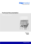
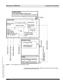
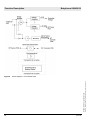
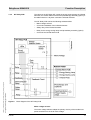
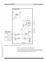
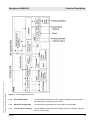
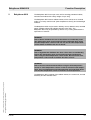
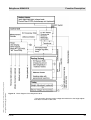
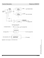
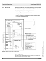
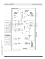
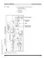
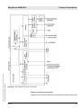
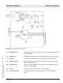
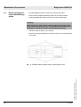
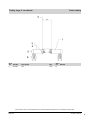
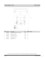
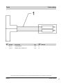
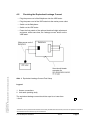
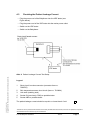
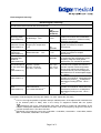
All rights reserved. Copyright reserved.
Version 2.1_ Released_Printed on_28.03.06_F6132300_Function_description.fm
Babytherm 8004/8010
Figure 7
6132.300
Function Description
Block diagram 2 of WT Power PCB
15


![[Competition Commission Undertaking No [ ] of 2004]](http://vs1.manualzilla.com/store/data/006010311_1-21996dba8872f587e5a78ef073ded048-150x150.png)