1
I
a
2002 IMPREZA SERVICE MANUAL
QUICK REFERENCE INDEX
~~
CHASSIS SECTION
c-
.
This service manual has been prepared
to provide SUBARU service personnel
with the necessary information and data
for the correct maintenance and repair
of SUBARU vehicles.
This manual includes the procedures
for maintenance, disassembling, reassembling, inspection and adjustment of
components and diagnostics for guidance of experienced mechanics.
Please peruse and utilize this manual
fully to ensure complete repair work for
satisfying our customers by keeping
their vehicle in optimum condition.
When replacement of parts during
repair work is needed, be sure to use
SUBARU genuine parts.
All information, illustration and specifications contained in this manual are
based on the latest product information
available at the time of publication
approval.
FUJI HEAVY INDUSTRIES LTD.
G18306E5
FRONT SUSPENSION
FSr
1.
2.
3.
4.
5.
6.
7.
8.
9.
c-
.
General Description ....................................................................................
Wheel Alignment .........................................................................................
Sub Frame ................................................................................................
Front Transverse Link ...............................................................................
Front Ball Joint ..........................................................................................
Front Strut .................................................................................................
Front Stabilizer ..........................................................................................
Front Crossmember ..................................................................................
General Diagnostic Table..........................................................................
2
8
16
17
19
20
24
25
26
I
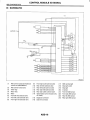
GENERAL DESCRIPTION
FRONT SUSPENSION
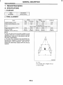
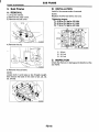
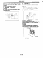
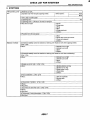
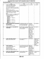
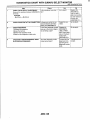
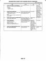
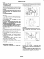
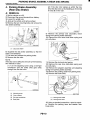
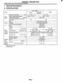
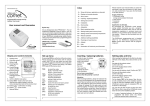
1. General Description
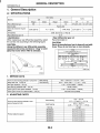
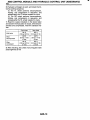
A: SPECIFICATIONS
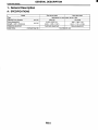
1. STABILIZER
Model
ALL MODEL
Bar diameter.
20 mm (0.79 in)
2. WHEEL ALIGNMENT
Sedan
Model
Caster (common difference: f0'45')
3'35'
I
14"35'
396 mm
(15.59 in)
I
I
Toe-in
I Kingpin angle (tolerance: +0"45')
Wheel arch height
[tolerance: f 1 2 mm (f0.47 in)]
I
Wagon
I
3'35'
I 3'25'
II
3'25'
. ~I
0+3 mm (Of0.12 in)
Each toe anale: kO"O7'30 (Total toe anale: fO"15')
14"20'
I 13"45' I 13"30' I
13'20'
406 mm
387 mm
397 mm
402 mm
(15.98 in)
(15.24 in)
(15.63 in)
(15.83 in)
3'25'
I
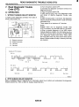
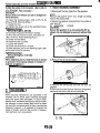
AOTE:
Front and rear toe-ins and front camber can be
adjusted. If the toe-in or camber tolerance exceeds
specifications,adjust toe-in and camber to the middle value of specification.
The other items indicated in the specification table cannot be adjusted. If the other items exceeds
specifications, check suspension parts and connections for deformities; replace with new ones as
required.
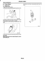
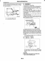
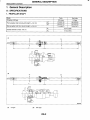
B4M2250B
(1) Front
A - B = Positive: Toe-in, Negative: Toe-out
a = Each toe angle
FS-2
I
GENERAL DESCRIPTION
FRONT SUSPENSION
c-
.
FS-3
GENERAL DESCRIPTION
FRONT SUSPENSION
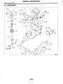
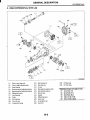
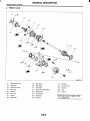
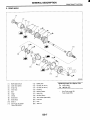
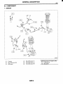
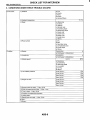
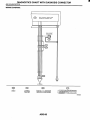
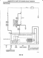
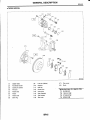
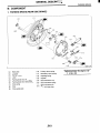
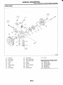
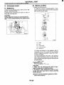
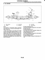
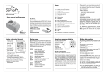
B: COMPONENT
FS-4
GENERAL DESCRIPTION
FRONT SUSPENSION
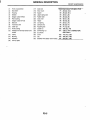
Front crossmember
Bolt ASSY
Housing
Washer
Stopper rubber (Rear)
Rear bushing
Stopper rubber (Front)
Ball joint
Transverse link
Cotter pin
Front bushing
Stabilizer link (Except sedan turbo
model)
Clamp
Bushing
Stabilizer
Jack-up plate
Dust seal
Tightening torque: N.m (kgf-m, ft-lb)
Strut mount
T I : ZO(2.0, 14.5)
T2: 25 (2.5, 18.1)
Spacer
Upper spring seat
T3: 30 (3.1,22)
Rubber seat
T4: 34 (3.5,25)
Dust cover
T5: 40 (4.1, 30)
Helper
T6: 45 (4.6, 33)
Coil spring
T7: 50 (5.1, 37)
Damper strut
T8: 55 (5.6, 41)
Adjusting bolt
T9: 71 (7.2, 52)
T10: 100 (10.2, 74)
(27) Castle nut
T11: <Ref. to FS-17, INSPECTION,
(28) Self-locking nut
Sub Frame.>
Sub
frame
(29)
T12: 175 (17.8, 129)
(30) Cover
T13: 190(19.4, 140)
(311 Clip
(32) Stabilizer link (Sedan turbo model) T14: 250 (25.5, 184)
(17 )
(18)
(19)
(20)
(21)
(22)
(23)
(24)
(25)
(26)
1
.-
I
FS-5
GENERAL DESCRIPTION
FRONT SUSPENSION
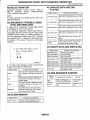
C: CAUTION
Wear working clothing, including a cap, protective goggles, and protective shoes during operation.
Remove contamination including dirt and corrosion before removal, installation or disassembly.
Keep the disassembled parts in order and protect them from dust or dirt.
Before removal, installation or disassembly, be
sure to clarify the failure. Avoid unnecessary removal, installation, disassembly, and replacement.
Use SUBARU genuine grease etc. or the equivalent. Do not mix grease etc. with that of another
grade or from other manufacturers.
Be sure to tighten fasteners including bolts and
nuts to the specified torque.
Place shop jacks or safety stands at the specified
points.
Apply grease onto sliding or revolution surfaces
before installation.
- Before installing O-rings or snap rings, apply sufficient amount of grease to avoid damage and deformation.
Before securing a part on a vice, place cushioning material such as wood blocks, aluminum plate,
or shop cloth between the part and the vice.
c-
FS-6
GENERAL DESCRIPTION
FRONT SUSPENSION
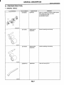
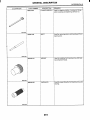
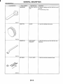
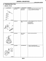
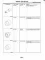
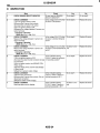
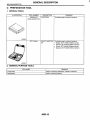
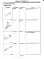
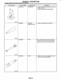
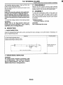
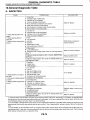
D: PREPARATION TOOL
1. SPECIAL TOOLS
REMARKS
sed as an adapter for camber & caster gauge
,hen measuring camber and caster.
I ) 28199AC000 PLATE
2) 28199AC010 BOLT
TOOL NUMBER
927380002
ILLUSTRATION
~
927680000
NSTALLER &
3EMOVER SET
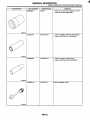
Jsed for replacing transverse link bushing.
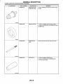
927760000
STRUT MOUNT
SOCKET
Used for disassembling and assembling strut
and shock mount.
84M2385
2. GENERAL PURPOSE TOOLS
TOOL NAME
Alignment gauge
Turning radius gauge
Toe-in gauge
Dial gauge
REMARKS
Used for wheel alignment measurement.
Used for wheel alignment measurement.
Used for toe-in measurement.
Used for damper strut measurement.
FS-7
I
WHEEL ALIGNMENT
FRONT SUSPENSION
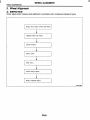
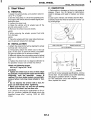
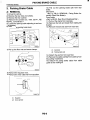
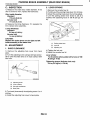
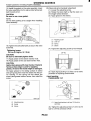
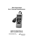
2. Wheel Alignment
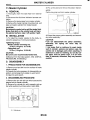
A: INSPECTION
Check, adjust and/or measure wheel alignment in accordance with procedures indicated in figure:
WHEEL ARCH HEIGHT (FRONT AND REAR)
1
CAMBER (FRONT AND REAR)
FRONT TOE-IN
REAR TOE-IN
THRUST ANGLE (REAR)
WHEEL STEERING ANGLE
B4M1OBBA
FS-8
I
I
WHEEL ALIGNMENT
FRONT SUSPENSION
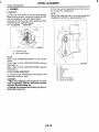
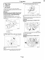
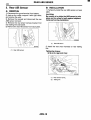
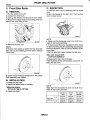
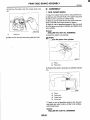
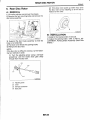
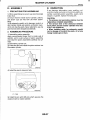
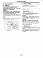
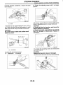
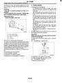
1. WHEEL ARCH HEIGHT
1) Adjust the tire pressure to specifications.
2) Set the vehicle under “curb weight” conditions. (Empty luggage compartment, install spare tire, jack, service tools, and top up fuel tank.)
3) Set the steering wheel in a wheel-forward position.
4) Suspend a thread from wheel arch (point “ A in figure below) to determine the point directly above center
of spindle.
5 ) Measure the distance between measuring point “ A and center of spindle.
c
E
t
.-m
a,
m
.a,
a,
..c
c
c
c
E
2
2
m
m
.-c
a,
a,
.c
c
3
c
5
L
m
-a,a,
aa,
f
-a,
a,
c
C
e
LL
7
m
2
End of spindle;,y//,/
suo009
Model
~
Sedan
Wagon
OUTBACK
I
Front
I
Specified wheel arch height
Turbo
Non-turbo
~~
396k12 mm (15.59k0.47in)
406kl2 mm (15.98k0.47in)
381532 mm (15.0k0.47in)
397k12 mm (1 5.63k0.47in)
Rear
376k12 mm (14.80k0.47in)
387k12 mm (15.24k0.47in)
376+12 mm (14.80k0.47in)
Front
-
381332 mm (15.0k0.47in)
402k12 mm (15.83k0.47in)
Rear
-
386k12 mm (15.20k0.47in)
Rear
Front
FS-9
I
WHEEL ALIGNMENT
FRONT SUSPENSION
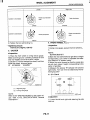
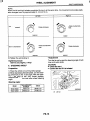
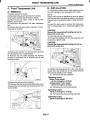
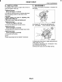
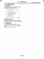
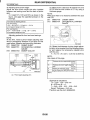
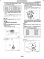
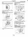
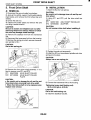
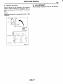
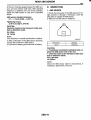
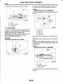
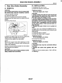
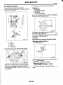
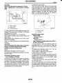
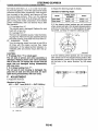
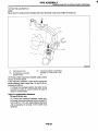
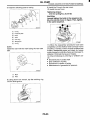
2. CAMBER
Inspection
1) Place the front wheel on turning radius gauge.
Make sure the ground contacting surfaces of front
and rear wheels are set at the same height.
2) Set the ST into the center of the wheel, and then
install the wheel alignment gauge.
ST 927380002 ADAPTER
c-
~
2) Turn the camber adjusting bolt so that the camber is set at the specification.
NOTE:
Moving the adjusting bolt by one scale graduation
changes the camber by approximately 0’10’.
(1) Alignment gauge
(2) Turning radius gauge
NOTE:
Refer to the ‘SPECIFICATIONS” for the camber
va Iues.
Front: <Ref. to FS-2, SPECIFICATIONS, General
Description.>
Rear: <Ref. to RS-2, SPECIFICATIONS, General
Description.>
Front camber adjustment
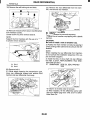
1) Loosen the two self-locking nuts located at the
lower front portion of strut.
CAUTION:
When the adjusting bolt needs to be loosened or tightened, hold its head with a wrench
and turn the self-locking nut.
Discard the loosened self-locking nut and replace with a new one.
FS-10
J
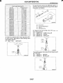
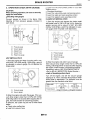
(1)
(2)
(3)
(4)
(5)
(6)
(7)
Strut
Adjusting bolt
Housing
Outer
Inner
Camber is increased.
Camber is decreased.
I
I
WHEEL ALIGNMENT
FRONT SUSPENSION
~
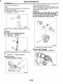
Right side
Left side
@)
Camber is increased.
@
I
J
;hte
counterclock-
Rotate clockwise.
u
B4M03Gn
04M0190
Camber is decreased.
@
I
Rotate clockwise.
@
‘
;?:e counterclock-
W
B4M0190
B4M0350
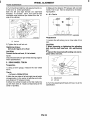
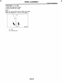
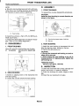
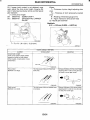
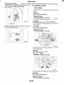
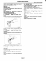
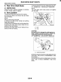
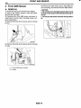
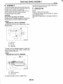
4. FRONT WHEEL TOE-IN
Inspection
3 ) Tighten the two self-locking nuts.
--Tightening torque:
175 N.m (1 7.8 kgf-m, 129 ft-lb)
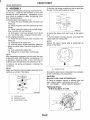
1) Using a toe gauge, measure the front wheel toein.
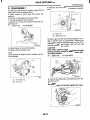
3. CASTER
Inspection
1) Place the front wheel on turning radius gauge.
Make sure the ground contacting surfaces of front
and rear wheels are set at the same height.
2) Set the ST into the center of the wheel, and then
install the wheel alignment gauge.
ST 927380002
ADAPTER
Toe-in:
Of3 mm (OdU. 12 in)
2) Mark the rear sides of left and right tires at height
corresponding to the center of spindles and measure distance “ A between marks.
3) Move the vehicle forward so that the marks line
up with front sides at height corresponding to the
center of spindles.
4) Measure the distance “ 6 between left and the
right marks. Toe-in can then be obtained by the following equation:
A - B = Toe-in
B
A
i
(1) Alignment gauge
(2) Turning radius gauge
NOTE:
Refer to the ‘SPECIFICATIONS’ for the caster values. <Ref. to FS-2, SPECIFICATIONS, General
Description.>
i
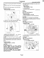
Adjustment
1) Loosen the left and right side steering tie-rods
lock nuts.
FS-11
I
WHEEL ALIGNMENT
FRONT SUSPENSION
2) Turn the left and right tie rods equal amounts until the toe-in is at the specification.
Both the left and right tie-rods are right-hand
threaded. To increase toe-in, turn both tie-rods
clockwise equal amounts (as viewed from the inside of the vehicle).
4) Measure the distance “B” between left and right
marks. Toe-in can then be obtained by the following equation:
A
- B = Toe-in
I
-
S4M0348A
(1) Lock nut
3) Tighten the tie-rod lock nut.
Tightening torque:
83 N-m (8.5kgf-m, 61.5 ff-lb)
CAUTION:
Correct the tie-rod boot, if it is twisted.
NOTE:
Check that the left and right wheel steering angle is
within specifications.
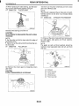
Adjustment
1) Loosen the self-locking nut on inner side of link
rear.
CAUTION:
When loosening or tightening the adjusting
bolt, hold the bolt head and turn self-locking
nut.
Discard the loosened self-locking nut and replace with a new one.
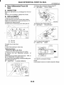
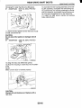
5. REAR WHEEL TOE-IN
Inspection
1) Using a toe-in gauge, measure the rear wheel
toe-in.
Toe-in:
-132 mm (-0.039fo.079 in)
2) Mark the rear sides of left and right tires at height
corresponding to the center of spindles and measure distance “A” between marks.
3) Move the vehicle forward so the that marks line
up with front sides at height corresponding to the
center of spindles.
(1) Adjusting bolt
(2) Link rear
2) Turn the adjusting bolt head until toe-in is at the
specification.
FS-12
I
WHEEL ALIGNMENT
FRONT SUSPENSION
NOTE:
When the left and right wheels are adjusted for toe-in at the same time, the movement of one scale graduation changes toe-in by approximately 1.5 mm (0.12 in).
Right side
Left side
~~
Rotate counterclockwise.
Rotate clockwise.
Toe-in is increased.
B4M0352
B4M0192
~~
Rotate counterclockwise.
c
Toe-in is decreased.
Rotate clockwise.
84M0192
B4M0352
1) Tighten the self-locking nut.
Tightening torque:
100 N-m (10.2 kgf-m, 74 ft-lb)
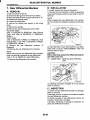
6. STEERING ANGLE
Inspection
1) Place the vehicle on a turning radius gauge.
2) While depressing the brake pedal, turn the steering wheel fully to the left and right. With the steering wheel held at each fully turned position,
measure both the inner and outer wheel steering
angle.
Adjus ment
Turn the tie-rod to adjust the steering angle of both
inner and outer wheels.
CAUTION:
Check the toe-in.
Correct the boot if it is twisted.
-
Steering angle:
Turbo,sedan and
Model
Others
OUTBACK
S4M0348A
Outerwheel
I
29"35"f1.5"
I
~~
31"35Y1.5"
(1) Locknut
FS-13
I
WHEEL ALIGNMENT
FRONT SUSPENSION
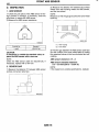
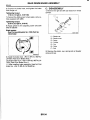
7. THRUST ANGLE
Inspection
1) Position the vehicle on a level surface.
2) Move the vehicle 3 to 4 meters directly forward.
3) Determine the locus of both front and rear axles.
4) Measure the distance “L” between center line of
loci of the axles.
3) When the left and right adjusting bolts are turned
incrementally by one graduation in the same direction, the thrust angle will change approximately 16’
[‘I“
is almost equal to 12 mm (0.472 in)].
Thrust angle:
O”f20’
Thrust angle:
Less than 20‘ when “L” is equal to or less
than 15 mm (59 in).
c-
.
M
T
S4M0350B
(1) Center line of loci (front axle)
(2) Center line of loci (rear axle)
S4M0350B
(1) Center line of loci (front axle)
(2) Center line of loci (rear axle)
Adjustment
1) Make the thrust angle adjustments by turning
toe-in adjusting bolts of rear suspension equally in
the same direction.
2) When one rear wheel is adjusted in a toe-in direction, adjust the other rear wheel equally in toeout direction, in order to make the thrust angle adjustment.
NOTE:
Thrust angle refers to a mean value of left and right
rear wheel toe angles in relation to the vehicle
body center line. Vehicle is driven straight in the
thrust angle direction while swinging in the oblique
direction depending on the degree of the mean
thrust angle.
(11
t
(1) Front
(2) Thrust angle
(3) Body center line
FS-14
I
WHEEL ALIGNMENT
Thrust angle: r = (a- p)/2
a: Right rear wheel toe-in angle
p: Left rear wheel toe-in angle
NOTE:
Here, use only positive toe-in values from each
wheel to substitute for a and p in the equation.
B4M01948
(1) Front
(2) Body center line
c.
FS-15
I
FRONT SUSPENSION
SUB FRAME
FRONT SUSPENSION
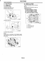
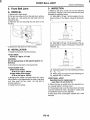
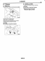
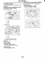
3. Sub Frame
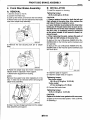
B: INSTALLATION
Install in the reverse order of removal.
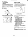
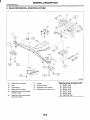
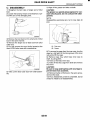
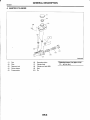
A: REMOVAL
NOTE:
Replace the M12 bolt with a new one.
1) Lift-up the vehicle.
2) Remove the under cover.
3) Remove the bolt cover.
Tightening torque:
T1: 34 N.m (3.5 kgf-m, 25 ff-lb)
T2: 55 N-m (5.6 kgf-m, 41 ff-lb)
T3: 71 N.m (7.2 kgf-m, 52 ff-lb)
T4: 105 N-m (10.7 kgf-m, 77 ff-lb)
4) Remove the clip.
(1)
(2)
(3)
(4)
5) Remove the sub frame.
NOTE:
Loosen bolt (1) and leave a few threads caught,
then remove the bolts in the order of (2),(3), (4),
(51,and (6).
FS-16
M8 bolt
M12 bolt (with max)
M12 bolt (with oil)
M10 bolt
SUB FRAME
FRONT SUSPENSION
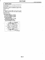
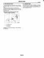
C: INSPECTION
1) Check that there is no damage and distortion at
the sub frame.
2) Check that the bolts are tightened with the specified torque. If there is looseness, tighten to the
specified torque.
NOTE:
The tightening torque differs by the color for bolt
(3). Always verify the bolt color before checking
tightening torque.
Tightening torque:
T I : 34 N-m (3.5 kgf-m, 25 ff-lb)
T2: 55 N.m (5.6 kgf-m, 41 ff-lb)
T3: 71 N-m (7.2 kgf-m, 52 ff-lb)
T4: Dark green bolt
105 Nom(10.7 kgf-m, 77 ff-lb)
T4: Except dark green bolt
55 N-m (5.6 kgf-m, 41 ff-lb)
FS-17
SUB FRAME
FRONT SUSPENSION
3. Sub Frame
B: INSTALLATION
Install in the reverse order of removal.
NOTE:
Replace the M12 bolt with a new one.
A: REMOVAL
1) Lift-up the vehicle.
2) Remove the under cover.
3) Remove the bolt cover.
Tightening torque:
T1: 34 N-m (3.5 kgf-my25 ft-16)
T2: 55 N-m (5.6 kgf-my41 ft-16)
T3: 71 N-m (7.2 kgf-my52 ft-16)
4) Remove the clip.
(1) M8 bolt
(2) M12 bolt
(3) MlO bolt
C: INSPECTION
Check that there is no damage and distortion at the
sub frame.
5 ) Remove the sub frame.
NOTE:
Loosen bolt (1) and leave a few threads caught,
then remove the bolts in the order of (2),(3), (4),
(5),and (6).
FS-16
I
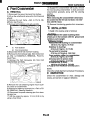
FRONT TRANSVERSE LINK
FRONT SUSPENSION
B: INSTALLATION
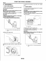
4. Front Transverse Link
A: REMOVAL
1) Set the vehicle on the lift.
2) Disconnect the ground terminal from battery.
3) Lift-up the vehicle and remove the wheel.
4) Remove the sub frame. <Ref. to FS-16, REMOVAL, Sub Frame.>
5) Disconnect the stabilizer link from transverse
link.
6) Remove the bolt securing the ball joint of transverse link to housing.
c.
1) Temporarily tighten the two bolts used to secure
the rear bushing of the transverse link to body.
NOTE:
These bolts should be tightened to such an extent
that they can still move back and forth in the oblong
shaped hole in the bracket (which holds the bushing).
2) Install the bolts used to connect the transverse
link to crossmember and temporarily tighten with
nut.
CAUTION:
Discard the loosened self-locking nut and replace with a new one.
3) Insert the ball joint into housing.
4) Connect the stabilizer link to transverse link, and
temporarily tighten bolts.
CAUTION:
Discard the loosened self-locking nut and replace with a new one.
S4MOO9(
7) Remove the nut (do not remove bolt.) securing
the transverse link to crossmember.
8) Remove the two bolts securing the bushing
bracket of transverse link to vehicle body at rear
bushing location.
"
S4M0090
5) Tighten the following points in the order shown
below when the wheels are in full contact with the
ground and vehicle is curb weight.
(1) Transverse link and stabilizer
9) Extract the ball joint from housing.
10) Remove the bolt securing the transverse link to
crossmember and extract the transverse link from
crossmember.
Tightening torque:
Sedan Turbo model:
45 N.m (4.6 kgf-m, 33 ft-lb)
Except sedan Turbo model:
30 N m (3.1 kgf-m, 22 ft-lb)
(2) Transverse link and crossmember
Tightening torque:
100 N-m (10.2 kgf-m, 74 ft-lb)
(3) Transverse link rear bushing and body
Tightening torque:
250 N-m (25.5 kgf-m, 184 ff-16)
FS-17
I
FRONT TRANSVERSE LINK
FRONT SUSPENSION
NOTE:
Move the rear bushing back and forth until transverse link-to-rear bushing clearance is established
(as indicated in figure.) before tightening.
Unit: mm (in)
.059)
D: ASSEMBLY
1. FRONT BUSHING
To reassemble, reverse disassembly procedures.
CAUTION:
Install the front bushing in correct direction, as
shown in the figure.
(1) Rear bushing
6) Install the sub frame. <Ref. to FS-16, INSTALLATION, Sub Frame.>
7) Inspect the wheel alignment and adjust if necessary. <Ref. to FS-8, Wheel Alignment.>
S4M0351A
(1) Face bushing toward center of ball joint
(2) Ball joint
C: DISASSEMBLY
2. REAR BUSHING
1. FRONT BUSHING
1) Install the rear bushing to transverse link and
align the aligning marks scribed on the two.
2) Tighten the self-locking nut.
CAUTION:
Discard the loosened self-locking nut and replace with a new one.
While holding the rear bushing so as not to
change position of aligning marks, tighten the
self-locking nut.
Using ST, press the front bushing out of place.
ST 927680000
INSTALLER & REMOVER
SET
Tightening torque:
190 N-m (19.4 kgf-m, 140 ff-lb)
E: INSPECTION
G4M0494
2. REAR BUSHING
1) Scribe an aligning mark on the transverse link
and rear bushing.
2) Loosen the nut and remove the rear bushing.
G4M0495
1) Check the transverse link for wear, damage and
cracks, and correct or replace if defective.
2) Check the bushings for cracks, fatigue or damage.
3) Check the rear bushing for oil leaks.
I
FS-18
I
FRONT BALL JOINT
FRONT SUSPENSION
C: INSPECTION
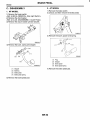
5. Front Ball Joint
A: REMOVAL
1) Remove the front wheel.
2) Pull out the cotter pin from the ball stud, remove
the castle nut, and extract the ball stud from the
transverse link.
3) Remove the bolt securing the ball joint to the
housing.
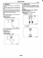
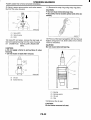
1) Measure the play of ball joint by the following
procedures. Replace with a new one when the play
exceeds the specified value.
(1) With 686 N (70 kgf, 154 Ib) loaded in the direction shown in the figure, measure dimension
e 1.
-
G4M0500
(2) With 686 N (70 kgf, 154 Ib) loaded in the opposite direction shown in the figure, measure dimension e,.
\
G4M0499
--4)-€xtract the ball joint from the housing.
B: INSTALLATION
I
1) Install the ball joint onto the housing.
4
Torque (Bolt):
50 N-m (5-7 kgf-m, 37 ft-lb)
CAUTION:
Do not apply grease to the tapered portion of
ball stud.
2) Connect the ball joint to transverse link.
Torque (Castle nut):
Sedan turbo model:
30 N-m (3.7 kgf-m, 22ft-lb)
Except sedan turbo model:
45 N.m (4.6 kgf-m, 33ft-lb)
3) Retighten the castle nut further within 60" until a
slot in castle nut is aligned with the hole in ball stud
end, then insert the new cotter pin and bend it
around castle nut.
4) Install the front wheel.
G4M0501
(3) Calculate plays from the following formula.
S= Q2 - 0 1
(4) When plays are larger than the following value, replace with a new one.
FRONT BALL JOINT
Specified play for replacement: S
Less than 0.3 mm (0.012 in)
2) When the play is smaller than the specified value, visually inspect the dust cover.
3) The ball joint and cover that have been removed
must be checked for wear, damage or cracks, and
any defective part must be replaced.
4) If the dust cover is damaged, replace with a new
ball joint.
FS-19
I
FRONT STRUT
FRONT SUSPENSION
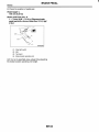
6. Front Strut
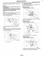
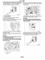
6) Remove the three nuts securing strut mount to
body.
A: REMOVAL
1) Remove the front wheel.
2) Remove the bolt securing brake hose from strut.
R4Mi78A
3) Scribe an alignment mark on the camber adjusting bolt which secures strut to housing.
4) Remove the bolt securing the ABS sensor harness.
suo011
5 ) Remove the two bolts securing housing to strut.
CAUTION:
While holding the head of adjusting bolt, loosen
self-locking nut.
FS-20
I
I
FRONT STRUT
FRONT SUSPENSION
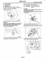
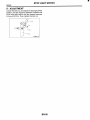
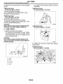
B: INSTALLATION
C: DISASSEMBLY
1) Install the strut mount at upper side of strut to
body and tighten with nuts.
1) Using a coil spring compressor, compress the
coil spring.
Tightening torque:
20 N-m (2.0 kgf-m, 74.5 ft-lb)
2) Position the aligning mark on camber adjustment
bolt with aligning mark on lower side of strut.
CAUTION:
While holding the head of adjusting bolt,
tighten self-locking nut.
Be sure to use a new self-locking nut.
Tightening torque:
775 N-m (77.8 kgf-m, 729 ft-lb)
3 ) Install the ABS sensor harness to strut.
S4M0095
Tightening torque:
33 N.m (3.4 kgf-m, 24.3 ft-lb)
4) Install bolts which secure the brake hose to strut.
2) Using the ST, remove the self-locking nut.
ST 927760000
STRUT MOUNT SOCKET
-_Tightening torque:
33 N-m (3.4 kgf-m, 24.3 ft-lb)
5 ) Install the front wheels.
NOTE:
Check wheel alignment and adjust if necessary.
3) Remove the strut mount, upper spring seat and
rubber seat from strut.
4) Gradually decreasing the compression force,
and remove the coil spring.
5 ) Remove the dust cover and helper spring.
FS-21
I
FRONT STRUT
FRONT SUSPENSION
D: ASSEMBLY
1) Before installing the coil spring, strut mount, etc.,
on the strut, check for the presence of air in the
dampening force generating mechanism of the
strut since air prevents proper dampening force
from being produced.
2) Checking for the presence of air:
(1) Place the strut vertically with the piston rod
facing up.
(2) Move the piston rod to the center of its entire
stroke.
(3) While holding the piston rod end with fingertips, move the rod up and down.
(4) If the piston rod moves at least 10 mm (0.39
in) in the former step, purge air from the strut.
3) Air purging procedure:
(1) Place the strut vertically with the piston rod
facing up.
(2) Fully extend the piston rod.
(3) With the piston rod fully extended, place the
-piston rod side down. The strut must stand vertically.
(4) Fully contract the piston rod.
(5) Repeat 3 or 4 times from the first step.
NOTE:
After completely purging air from the strut, be sure
to place the strut with the piston rod facing up. If it
is laid down, check for entry of air in the strut as
outlined under “Checking for the presence of air”.
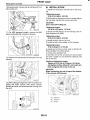
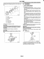
4) Using a coil spring compressor, compress the
coil spring.
NOTE:
Make sure that the vertical installing direction of coil
spring is as shown in the figure.
--
(2
5) Set the coil spring correctly so that its end face
fits well into the spring seat as shown.
I
S4M0353A
6) Install the helper and dust cover to the piston
rod.
7) Pull the piston rod fully upward, and install the
rubber seat and spring seat.
NOTE:
Ensure the upper spring seat is positioned as
shown in the figure.
4
(1)
(1) Outside of body
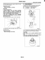
8) Install the strut mount to the piston rod, and tighten the self-locking nut temporarily.
CAUTION:
Be sure to use a new self-locking nut.
9) Using a hexagon wrench to prevent strut rod
from turning, tighten self-locking nut with ST.
ST 927760000
STRUT MOUNT SOCKET
Tightening torque:
55 N.m (5.6 kgf-m, 41 ft-lb)
I
B4M0568B
S4M0097B
I
(1) Fiat (top side)
(2) identificationpaint
(3) inclined (bottom side)
FS-22
I
FRONT STRUT
FRONT SUSPENSION
10) Loosen the coil spring carefully.
5. HELPER
E: INSPECTION
Replace it with a new one if cracked or damaged.
Check the disassembled parts for cracks, damage
and wear, and replace with new parts if defective.
F: DISPOSAL
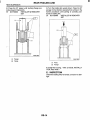
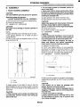
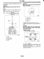
1. DAMPER STRUT
1) Check for oil leakage.
2) Move the piston rod up and down to check that it
operates smoothly without any binding.
3) Play of piston rod
Measure the play as follows:
Fix the outer shell and fully extend the rod. Set a
dial gauge at the end of the rod: L [ l o mm (0.39
in)], then apply a force of W [20 N (2 kgf, 4 Ib)] to
threaded portion. With the force of 20 N (2 kgf, 4 Ib)
applied, read the dial gauge indication: PI. Apply a
force of 20 N (2 kgf, 4 Ib) in the opposite direction
of “W”, then read the dial gauge indication: P.,
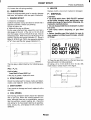
CAUTION:
On struts which have “GAS FILLED” marked
on the outer housing under spring seat, completely discharge the gas before disposing, following the methods below.
Do not disassemblethe strut damper or place
into a fire.
Drill holes before disposing of gas filled
struts.
Before handling gas filled struts, be sure to
wear goggles to protect eyes from gas, oil and/
or filings.
GAS FILLED
DO NOT OPEN
DO NOT HEAT
I
The free play is determined by the following equation:
B4M1201
1) Place the gas filled strut on a flat and level surface with piston rod fully extended.
2) Using a 2 to 3 mm (0.08 to 0.12 in) dia. drill,
make holes in areas shown in the figure.
Play = PI, P2
I
Limit of play:
Less than 0.8 mm (0.031 in)
If the play is greater, replace the strut.
2. STRUT MOUNT
Check the rubber part for creep, cracks and deterioration, and replace it with a new one if defective.
3. DUSTCOVER
If any cracks or damage are found, replace it with a
new one.
4. COIL SPRING
One having permanent strain should be replaced
with a new one. When the vehicle posture is uneven, although there are no considerable reasons
like tire puncture, uneven loading, etc., check the
coil spring for its free length referring to specifications, cracks, etc., and replace it with a new one if
defective.
FS-23
piston
rod
,-Strut
M
(1.57 in)
B4M1202P
I
FRONT STABILIZER
FRONT SUSPENSION
7. Front Stabilizer
B: INSTALLATION
1) Install in the reverse order of removal.
A: REMOVAL
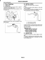
Jack-up the front part Of the vehicleand
it with safety stands (rigid racks).
2, Remove the j a c k w plate from lowerpart Of
crossmember.
3) Remove the sub frame. <Ref. to FS-16,RELbVAL, Sub Frame.>
4) Remove the bolt and nut which secure the stabilizer to crossmember.
NOTE:
Install the bushing (on front crossmember side)
while aligning it with paint mark on stabilizer.
Ensure the bushing and stabilizer have the Same
identification colors when installing.
''
c-
suo012
(1) Mark stamped on stabilizer
(2) Bushing identification color
-
5 ) Remove the bolts which Secure the stabilizer link
to front transverse link.
2)Always tighten the rubber bushing location when
wheels are in full contact with the ground and vehicle is curb weight.
Tightening torque (Sedan turbo model):
Jack-up plate to crossmember:
20 Nom(2.0 kgf-m, 14.5 ft-lb)
Stabilizer link to front transverse link:
45 N-m (4.6 kgf-m, 33 ft-lb)
Stabilizer to crossmember:
25 N.m (2.5 kgf-m, 18.1 ft-lb)
Tightening torque (Except sedan turbo model):
Jack-up plate to crossmember:
20 N.m (2.0 kgf-m, 14.5 ft-lb)
Stabilizer link to front transverse link:
30 N.m (3.1 kgf-m, 22 ft-lb)
Stabilizer to crossmember:
25 N-m (2.5 kgf-m, 18.1 ft-lb)
3) Install the sub frame. <Ref. to FS-16, INSTALLATION, Sub Frame.>
C: INSPECTION
1) Check the bushing for cracks, fatigue or damage.
2) Check the stabilizer link for deformities, cracks
or damage, and bushing for protrusions from the
hole of stabilizer link.
FS-24
FRONT CROSSMEMBER
FRONT SUSPENSION
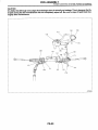
8. Front Crossmember
A: REMOVAL
1) Disconnect the ground terminal from battery.
2) Lift-up the vehicle and remove the front tires and
wheels.
3) Remove the sub frame. <Ref. to FS-16, REMOVAL, Sub Frame.>
4) Remove both stabilizer and jack-up plate.
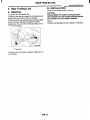
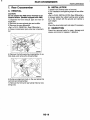
12) Support the crossmember with a jack, remove
the nuts securing crossmember to body and lower
crossmember gradually along with the steering
gearbox.
CAUTION:
When removing the crossmember downward,
be careful that the tie-rod end does not interfere with SFJ boot.
13) Remove the steering gearbox from crossmember.
B: INSTALLATION
1) Install in the reverse order of removal.
CAUTION:
Always tighten the rubber bushing when
wheels are in full contact with the ground and
vehicle is curb weight.
c.
(1) Front stabilizer
(2) Front crossmember
5) Disconnect the tie-rod end from housing.
6) Remove the front exhaust pipe. (Non-turbo model) <Ref. to. EX(S0HC)-5, REMOVAL, Front Exhaust Pipe.>
7 ) Remove the front transverse link from front
crossmember and body.
Tightening torque:
Transverse link bushing to crossmember:
100 N.m (10.2 kgf-m, 74 ft-lb)
Stabilizer to bushing:
25 N.m (2.5 kgf-m, 18.1 ft-lb)
Tie-rod end to housing:
27.0 N-m (2.75 kgf-m, 19.9 ft-lb)
Front cushion rubber to crossmember:
85 N.m (8.7 kgf-m, 62.7 ft-lb)
Universal joint to pinion shaft:
24 N-m (2.4 kgf-m, 17.4 ff-16)
Crossmember to body:
100 N-m (10.2 kgf-m, 74 ft-lb)
2) Purge air from the power steering system.
NOTE:
Check the wheel alignment and adjust if necessary.
C: INSPECTION
Check the crossmember for wear, damage and
cracks, and correct or replace if defective.
8) Remove the nuts attaching engine mount cushion rubber to crossmember.
9) Remove the steering universaljoint. <Ref. to PS26, REMOVAL, Steering Gearbox.>
10) Disconnect the power steering pipe from steering gear box.
11) Lift the engine by approx. 10 mm (0.39 in) by
using a chain block.
FS-25
I
GENERAL DIAGNOSTIC TABLE
FRONT SUSPENSION
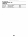
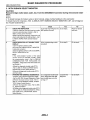
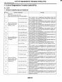
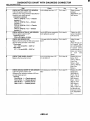
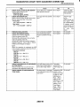
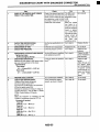
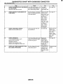
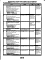
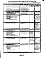
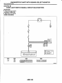
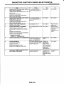
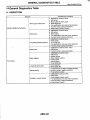
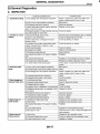
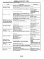
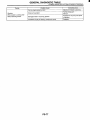
9. General Diagnostic Table
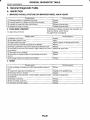
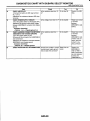
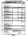
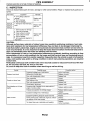
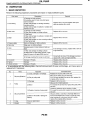
A: INSPECTION
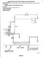
1. IMPROPER VEHICLE POSTURE OR IMPROPER WHEEL ARCH HEIGHT
Possible causes
Countermeasures
Replace.
Replace with proper parts.
Replace with proper parts.
(2) Unsmooth operation of damper strut and/or shock absorber
(3) Installation of wrong strut and/or shock absorber
(4) Installation of wrong coil spring
ning over bump and/or hump.
3) Large shock in bumping
1) Large rebound shock
I Replace.
(1) Breakage of coil spring
(2) Overinflation pressure of tire
I (3) Improper wheel arch height
(4) Fault in operation of damper strut and/or shock absorber
*(5)Damage or deformation of strut mount and/or shock absorber mount
(6) Unsuitability of maximum and/or minimum length of damper strut and/or
shock absorber
I Adjust.
I Adjust or replace coil springs with new ones.
I ( 7 ) Deformation or loss of bushing
I Replace.
(8) Deformationor damage of helper in strut assembly and/or shock
absorber
(9) Oil leakaae of damDer strut and/or shock absorber
I
I
Replace.
Replace.
Replace with proper parts.
I
Replace.
Replace.
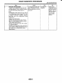
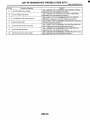
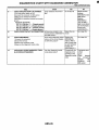
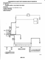
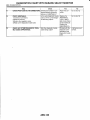
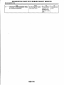
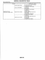
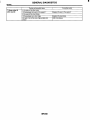
Countermeasures
Possible causes
(1 ) Wear or damage of damper strut and/or shock absorber component
parts
(2) Loosenina of suspension link installing bolt
(3) Deformation or loss of bushing
(4) Unsuitability of maximum and/or minimum length of damper strut and/or
shock absorber
(5) Breakaae of coil sprina
I (6) Wear or damaae of ball ioint
I (7) Deformation of stabilizer clamp
FS-26
Replace.
I Retighten to the specified torque.
1 Replace.
I
I
Replace with proper parts.
Replace.
I Replace.
I Replace.
I
I
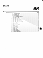
REAR SUSPENSION
RS
.
Page
1.
2.
3.
4.
5.
6.
7.
8.
General Description ....................................................................................
2
Wheel Alignment ......................................................................................... 9
Rear Stabilizer........................................................................................... 10
Rear Trailing Link ...................................................................................... 11
Rear Strut .................................................................................................. 15
Lateral link ................................................................................................. 16
19
Rear Crossmember ...................................................................................
General Diagnostic Table .......................................................................... 20
a
I
GENERAL DESCRIPTION
REAR SUSPENSION
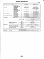
1. General Description
A: SPECIFICATIONS
Item
I Camber (tolerance: fO"45')
Turbo
I
Sedan
I Non-turbo
-1"30'
Toe-in
I
Wheel arch height
[tolerance:k12 mm (k0.47 in)l
Thrust angle
Diameter of stabilizer
376 m m
(14.80 in)
I
20 mm
(0.79 in)
I
1
I
Turbo
Wagon
1 Non-turbo
OUTBACK
-1'20'
I -1'15' I
-1"10'
- I f 2 mm (-0.039k0.079 in)
Each toe-in angle: fO"07'30 (Total toe-in angle 0"+15')
381 m m
386 m m
381 mm
376 m m
(15.0 in)
(15.20 in)
(15.0 in)
(14.80 in)
O"f20'
13mm
1 3 mm
17 mm
(0.51 in)
(0.67 in)
(0.51 in)
-1"25'
NOTE:
Front and rear toe-ins and front camber can be
adjusted. If the toe-in or camber tolerance exceeds
specifications, adjust the toe-in and camber to the
middle value of specification.
The other items indicated in the specification ta%le cannot be adjusted. If the other items exceeds
specifications, check the suspension parts and
connections for deformities; replace with new ones
as required.
B4M2250C
(1) Front
A - B = Positive: Toe-in, Negative: Toe-out
al, a2: Each toe-in angle
RS-2
I
I
3
GENERAL DESCRIPTION
REAR SUSPENSION
c.
RS-3
I
I
GENERAL DESCRIPTION
REAR SUSPENSION
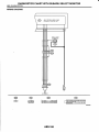
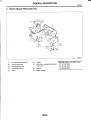
B: COMPONENT
P
I
SI
RS-4
GENERAL DESCRIPTION
REAR SUSPENSION
Stabilizer
Stabilizer bracket
Stabilizer bushing
Clamp
Floating bushing
Stopper
Stabilizer link
Rear lateral link
Bushing (C)
Bushing (A)
Front lateral link
Trailing link bracket
Cap (Protection)
Washer
Rear crossmember
Strut mount cap
Strut mount
Rubber seat upper
Dust cover
Coil spring
Helper
Rubber seat lower
Tightening torque: N-m (kgf-m, ft-lb)
T1: 20(2.0, 14.5)
T2: 25 (2.5, 18.1)
T3: 45 (4.6, 33.2)
T4: 55 (5.6, 4 1)
T5: 70 (7.1, 52)
T6: 90 (9.2, 66)
T7: 100 (10.2, 74)
T8: 115(11.7, 85)
T9: 130 (13.3, 96)
TlO: 135(13.8, 100)
Bushing (B)
Damper strut
T11: 220(22.4, 162)
Trailing link rear bushing
Trailing link
Trailing link front bushing
Self-locking nut
Rear differential member rear
c.
RS-5
I
GENERAL DESCRIPTION
REAR SUSPENSION
C: CAUTION
Wear working clothing, including a cap, protective goggles, and protective shoes during operation.
Remove contamination including dirt and corrosion before removal, installation or disassembly.
Keep the disassembled parts in order and protect them from dust or dirt.
Before removal, installation or disassembly, be
sure to clarify the failure. Avoid unnecessary removal, installation, disassembly, and replacement.
Use SUBARU genuine grease etc. or the equivalent. Do not mix grease etc. with that of another
grade or from other manufacturers.
Be sure to tighten fasteners including bolts and
nuts to the specified torque.
Place shop jacks or safety stands at the specified
points.
Apply grease onto sliding or revolution surfaces
before installation.
-0
Before installing O-rings or snap rings, apply sufficient amount of grease to avoid damage and deformation.
Before securing a part on a vice, place cushioning material such as wood blocks, aluminum plate,
or shop cloth between the part and the vice.
Before disposing shock absorbers, be sure to
bleed gas completely. Also, do not throw away in
fire.
RS-6
GENERAL DESCRIPTION
I
REAR SUSPENSION
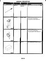
D: PREPARATION TOOL
1. SPECIAL TOOLS
I
DESCRIPTlON
rDAPTER
REMARKS
Jsed as an adapter for camber & caster gauge
vhen measuring camber and caster.
1) 28199ACOOO PLATE
2) 28199AC010 BOLT
927720000
NSTALLER &
3EMOVER
Jsed for replacing front bushing.
927730000
NSTALLER &
3EMOVER
Used for replacing rear bushing.
28099PA100
REMOVER
Used for removing DOJ.
TOOL NUMBER
927380002
ILLUSTRATION
1
B4M2378A
I
I
suo014
SUOOI!
RS-7
I
GENERAL DESCRIPTION
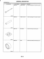
REAR SUSPENSION
ILLUSTRATION
TOOL NUMBER
92770000
DESCRIPTION
INSTALLER &
REMOVER
REMARKS
Used for replacing lateral link bushing.
927690000
HELPER SOCKET
WRENCH
Used for replacing lateral link bushing.
SUO015
SUO015
2. GENERAL PURPOSE TOOLS
TOOL NAME
Alignment gauge
Turnina radius aauae
IToe-in aauae
I Transmission iack
Bearing puller
I
REMARKS
Used for wheel alignment measurement.
Used for wheel alianment measurement.
I Used for toe-in measurement.
I Used for suspension assembly/disassembly.
I Used for removing bushings.
RS-8
I
I
I
WHEEL ALIGNMENT
REAR SUSPENSION
2. Wheel Alignment
A: INSPECTION
NOTE:
The front and rear wheel alignment must be measured and/or adjusted at once to obtain accuracy.
Measure and/or adjust the rear wheel alignment together with the front. Follow the procedure in "FS"
section "Wheel Alignment" for measurement and/or
adjustment of wheel alignment. <Ref. to FS-8, INSPECTION, Wheel Alignment.>
RS-9
I
REAR STABILIZER
REAR SUSPENSION
3. Rear Stabilizer
B: INSTALLATION
1) Install in the reverse order of removal.
A: REMOVAL
1) Jack-up the rear part of the vehicle, support it
with safety stands (rigid racks).
2) Remove the bolts which secure stabilizer link to
rear lateral link.
NOTE:
Install the bushing while aligning it with paint
mark on stabilizer.
Ensure that the bushing and stabilizer have the
same identification colors when installing.
3) Remove the bolt which secures stabilizer to stabilizer bracket.
c-
(1) Mark stamped on stabilizer
(2) Bushing identification color
-
2) Always tighten the rubber bushing location when
wheels are in full contact with the ground and vehicle is curb weight.
Tightening torque:
Stabilizer link to rear lateral link
45 N-m (4.6 kgf-m, 33.2 ft-lb)
Stabilizer to stabilizer bracket
25 N.m (2.5 kgf-m, 18.1 ft-lb)
C: INSPECTION
1) Check the bushing for cracks, fatigue or damage.
2) Check the stabilizer links for deformities, cracks,
or damage, and bushing for protrusions from the
hole of stabilizer link.
RS-10
1
REAR TRAILING LINK
REAR SUSPENSION
4. Rear Trailing Link
B: INSTALLATION
A: REMOVAL
1) Loosen the rear wheel nuts.
2)Jack-up the vehicle, SUPPofl it with safety stands
(rigid racks) and remove the rear wheels.
3) Remove both rear parking brake clamp and ABS
sensor harness. (Models equipped with ABS)
4) R~~~~~ the bolt which Secures trailing link to
trailing link bracket.
Install in the reverse order of removal.
CAUTION:
Always tighten the .rubber bushing location
when wheels are in full contact with the ground
and vehicle is at curb weight condition.
NOTE:
Check the wheel alignment and adjust if necessary.
(1) Trailing link
5 ) Remove the bolt which secures trailing link to
rear housing.
RS-11
REAR TRAILING LINK
REAR SUSPENSION
C: DISASSEMBLY
2. REAR BUSHING
1. FRONT BUSHING
1) Remove the housing. <Ref. to DS-23, REMOVAL, Rear Axle.>
2) Using ST, press the rear bushing out of place.
INSTALLER &-REMOVER
ST 927730000
SET
Using ST, press the front bushing out of place.
INSTALLER & REMOVER
ST 927720000
SET
c-
-
(1) Press
(2) Trailing link
(1) Press
(2) Housing
RS-12
REAR TRAILING LINK
I
REAR SUSPENSION
D: ASSEMBLY
2. REAR BUSHING
1. FRONT BUSHING
1) Using ST, press the bushing into trailing link.
ST 927730000
INSTALLER & REMOVER
SET
Using ST, press the bushing into trailing link.
ST 927720000
INSTALLER & REMOVER
SET
CAUTION:
When installing the bushing, turn ST plunger
upside down and press it until plunger end surface contacts trailing link end surface.
NOTE:
If it is difficult to press the bushing into trailing link,
apply water-diluted TIRE LUBE to the inner surface
of ST as a lubricant.
SPE ClFlED lubricant:
TIRE LUBE :water = 1 :3
‘ir
(2)
\
c-
(3)
\
S4M0360E
(1) Press
(2) Front bushing
(1) Press
(3) Trailing link
CAUTION:
Install the front bushing in proper direction, as
shown in the figure.
I
S4M0361A
(1) Front
RS-13
REAR TRAILING LINK
REAR SUSPENSION
2) Press the ST pluger until bushing flange protrudes beyond trailing link.
INSTALLER & REMOVER
ST 927730000
SET
r.
3) Turn the trailing link upside down. Press the ST
plunger in the direction opposite that outlines in the
former procedure until bushing is correctly positioned in trailing link.
INSTALLER & REMOVER
ST 927730060
SET
.
( 1 ) Plunger
(2) Flange
( 1 ) Press
(2) Plunger
4) Install the housing. <Ref. to DS-26, INSTALLATION, Rear Axle.>
E: INSPECTION
Check the trailing links for bends, corrosion or damage.
RS-14
I
I
REAR STRUT
REAR SUSPENSION
5. Rear Strut
B: INSTALLATION
A: REMOVAL
1) Remove the rear seat cushion and backrest.
(Sedan model)
2) Remove the strut cap of quarter trim. (Wagon
model)
3) Loosen the rear wheel nuts.
4) Jack-up the vehicle, support it with safety stands
(rigid racks) and remove the rear wheels.
5 ) Remove the brake hose clip and remove the
brake hose from rear strut.
1) Tighten the self-locking nut used to secure strut
mount to car body.
CAUTION:
Discard the loosened self-locking nut, and replace with a new one.
Tightening torque:
20 Nom(2.0 kgf-m, 14.5 ft-lb)
2) Tighten the bolts which secure rear strut to housing.
Tightening torque:
220 N.m (22.4 kgf-m, 162 ft-lb)
CAUTION:
Discard the loosened self-locking nut, and replace with a new one.
3) Install the brake hose to lower side of strut, then
insert brake hose clip.
CAUTION:
Check that the hose clip is positioned proper-
ly(1) Brake hose clip
(2) Brake hose
6) Remove -the bolts which secure rear strut to
housing.
Check the brake hose for twisting, or excessive tension.
(Model equipped with ABS)
Do not subject the ABS sensor harness to exces-sive tension.
4) Lower the vehicle and tighten wheel nut.
Tightening torque:
90 N-m (9.2 kgf-m, 66 ft-lb)
5 ) Sedan model:
Install the rear seat backrest and rear seat cushion.
Wagon model:
Install the strut cap to rear quarter trim.
NOTE:
Check wheel alignment and adjust if necessary.
C: DISASSEMBLY
7) Remove the nuts securing strut mount to body.
For disassembly of rear strut, refer to procedures
outlined under front strut as a guide. <Ref. to FS21, DISASSEMBLY, Front Strut.>
D: ASSEMBLY
Refer to Front Strut as a guide for assembly procedures.
<Ref. to FS-22, ASSEMBLY, Front Strut.>
E: INSPECTION
Refer to Front Strut as a guide for inspection procedures.
<Ref. to FS-23, INSPECTION, Front Strut.>
F: DISPOSAL
Refer to Front Strut as a guide for disposal procedures.<Ref. to FS-23, DISPOSAL, Front Strut.>
RS-15
LATERAL LINK
REAR SUSPENSION
6. Lateral link
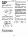
A: REMOVAL
1) Loosen the wheel nuts. Lift-up the vehicle and
remove wheel.
2) Remove the stabilizers. (Turbo model)
3) Remove the ABS sensor harness from trailing
link.
(Models eqipped with ABS)
4) Remove the bolt securing trailing link to housing.
r.
(1) Rear housing
(2) Trailing link
5) Remove the bolts which secure lateral link assembly to rear housing.
6) Remove the DOJ from rear differential using ST.
ST 28099PA100 DRIVE SHAFT REMOVER
NOTE:
The side spline shaft circlip comes out together
with the shaft.
I
(1) Bolt
(2) DOJ
CAUTION:
Be careful not to damage the side bearing retainer. Always use bolt shown in figure, as supporting point for ST during removal.
7) Scribe an alignment mark on the rear lateral link
adjusting bolt and crossmember.
RS-16
Bushing
Bushing A
Bushina B
BushinaC
I
ST:INSTALLER & REMOVER SET
927700000
927690000
927700000
I
LATERAL LINK
REAR SUSPENSION
D: ASSEMBLY
1) Using ST, press the bushing into place.
CAUTION:
Select the ST according to the type of bushings
used.
NOTE:
Use the same ST as that used during disassembly.
If it is difficult to press the bushing into trailing
link, apply water-diluted TIRE LUBE to the inner
surface of ST as a lubricant.
Specified lubricant:
TIRE LUBE :water = 1 :3
S4MQIQQ
(1) Bushing A
(2) Bushing B
(3) Bushing C
(4) Front
(5) Outside of body
(1) Press
(2) Bushing
(3) Lateral link
S4MQ365
(1) Press
(2) Lateral link
RS-17
I
LATERAL LINK
REAR SUSPENSION
2) Press the ST plunger until bushing flange protrudes beyond lateral link.
NOTE:
Use the same ST as that used during disassembly.
c
.
3) Turn the lateral link upside down. Press the ST
plunger in the direction opposite that outlined in the
former procedure until bushing is correctly positioned in trailing link.
NOTE:
Using the same ST as that used during dissassembly.
.
(1)
(2)
(3)
(4)
Press
Plunger
Lateral link
Flange
(1) Press
(2) Plunger
(3) Lateral link
E: INSPECTION
Visually check the lateral links for damage or
bends.
RS-18
I
I
REAR CROSSMEMBER
REAR SUSPENSION
B: INSTALLATION
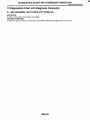
7. Rear Crossmember
A: REMOVAL
CAUTION:
Do not subject the ABS sensor harness to excessive tension. (Models equipped with ABS)
1) Separate the front exhaust pipe and rear exhaust pipe.
2) Remove the rear exhaust pipe and muffler.
3) Remove the rear differential.
<Ref. to DI-19, REMOVAL, Rear Differential.>
4) Place a transmission jack under rear crossmember.
1) Install in the reverse order of removal.
2) For installation and tightning torque of rear differential:
<Ref. to DI-20, INSTALLATION, Rear Differential.>
3) Always tighten the rubber bushing when wheels
are in full contact with the ground and vehicle is
curb weight.
NOTE:
Check the wheel alignment and adjust if necessary.
C: INSPECTION
Check the removed parts for wear, damage and
cracks, and correct or replace if defective.
5) Remove the bolts securing crossmember to vehicle body, and remove the crossmember.
6) Scribe an alignment mark on the rear lateral link
cam bolt and crossmember.
7) Remove the front and rear lateral links by loosening nuts.
RS-19
I
GENERAL DIAGNOSTIC TABLE
REAR SUSPENSION
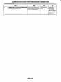
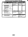
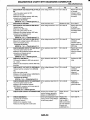
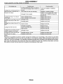
8. General Diagnostic Table
A: INSPECTION
1. IMPROPER VEHICLE POSTURE OR IMPROPER WHEEL ARCH HEIGHT
Possible causes
(1) Permanent distortion or breakage of coil spring
(2) Unsmooth operation of damper strut and/or shock absorber
I (3) Installation of wrong strut and/or shock absorber
(4) Installation of wrong coil spring
I
Countermeasures
Replace.
Replace.
I Replace with proper parts.
I Replace with proper parts.
I
I
2. POOR RIDE COMFORT
1) Large rebound shock
2) Rocking of vehicle continues too long after running over bump and/or hump.
3) Large shock in bumping
I (1) Breakage of coil
spring
I Replace.
I (2) Overinflation Dressure of tire
I Adiust.
(3) Improper wheel arch height
Adjust or replace coil springs with new ones.
44)Fault in operation of damper strut and/or shock absorber
II Replace.
'
t(5) Damaae or deformation of strut mount and/or shock absorber mount
I Replace.
(6) Unsuitabilityof maximum and/or minimum length of damper strut and/or Replace with proper parts.
shock absorber
(7) Deformation or loss of bushing
Replace.
(8) Deformation or damage of helper in strut assembly and/or shock
Replace.
absorber
I (9) Oil leakage of damper strut and/or shock absorber
1 Replace.
I
\
,
3. NOISE
Possible causes
(1) Wear or damage of damper strut and/or shock absorber component
parts
(2) Loosening of suspension link installing bolt
(3) Deformation or loss of bushing
(4) Unsuitability of maximum and/or minimum length of damper strut and/or
shock absorber
(5)Breakaae of coil sprina
(6) Wear or damage of ball ioint
I (7) Deformationof stabilizer clamp
RS-20
Countermeasures
Replace.
I Retighten to the specified torque.
I Replace.
I
I
Replace with proper parts.
Replace.
Replace.
I
I Replace.
I
I
WHEEL AND TIRE SYSTEM
WT
~~
~
1.
2.
3.
4.
5.
6.
7.
8.
page
General Description .................................................................................... 2
Tire .............................................................................................................. 4
Steel Wheel ................................................................................................. 5
Aluminum Wheel ......................................................................................... 6
Wheel Balancing .........................................................................................
7
“T-type” Tire ................................................................................................ 8
Full Wheel Cap ............................................................................................ 9
General Diagnostics Table ........................................................................ 10
I
GENERAL DESCRIPTION
WHEEL AND TIRE SYSTEM
~
~
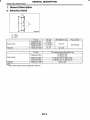
1. General Description
A: SPECIFICATIONS
S4M0367A
I
I
Front and rear
-*
.
T-Type tire
P195/60R1587H
P205/55 R16 89V
215/45 R17 87W
T I 35/70 D16 1OOM
I
15x6JJ
16 x 6 1/2JJ
17 x 7JJ
16 x 4T
Tire size
T-Type tire
55 (2.17)
I
100 (3.94) Dia.
50 (1.97)
Tire inflation pressure kPa (kg/cm2,psi)
Fr: 220 (2.2, 32)
Rr: 200 (2.0, 29)
Fr: 220 (2.2, 32) Fir: 200 (2.0, 29)
Fr: 230 (2.3, 33) Rr: 220 (2.2, 32)
420 (4.2, 60)
P I95/60 R15 87H
Front and rear
I
I
P205155 R16 89V
215/45 R17 87W
T135ffO D16 100M
WT-2
I
GENERAL DESCRIPTION
WHEEL AND TIRE SYSTEM
B: PREPARATION TOOL
1. SERVICE DATA
I
~
Item
Steel wheel
Aluminum wheel
I
Axial runout
I Radial runout
1.5 mm (0.059 in)
1.O mm (0.039 in)
1
1. GENERAL PURPOSE TOOLS
TOOL NAME
Air pressure gauge
Dial gauge
2. ADJUSTING PARTS
I n a m F iunbalance
I
Less than 5 g (0.18 02)
Balance weight part number
I
723141320
723141330
I
Weight
I
20 g (0.71 02)
I
723141350
723241380
723241590
Balance weight part number
(For aluminum wheel)
23141GA462
Weight
23141GA482
r
I
23141GA512
23141GA522
23141GA532
231
~- 41GA542
23141GA552
23141GA572
I
-I
30 g (1.06 02)
35 g (1.23 02)
40 g (1.41 02)
45 a (15 9 02)
50 g (I
.76 02)
55 g (1.94 0 2 )
60 g (2.12 02)
"
I
I
>
WT-3
REMARKS
Used for measuring tire air pressure.
Used for measuring wheel runout.
I
TIRE
WHEEL AND TIRE SYSTEM
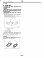
2. Tire
A: INSPECTION
1) Take stone, glass, nail etc. off the tread groove.
2) Replace the tire:
CAUTION:
When replacing a tire, make sure to use only
the same size, construction and load range as
originally installed.
Avoid mixing radial, belted bias or bias tires
on the vehicle.
(1) when large crack on side wall, damage or
crack on tread is found.
(2) when the “tread wear indicator” appears as
a solid band across the tread.
r.
.
-
I
S4M0377A
(1 ) Tread wear indicator
(2) Tire tread
1. TIRE ROTATION
If tires are maintained at the same positions for a
long period of time, uneven wear results. Therefore, they should be periodically rotated.
This lengthens service life of tires.
CAUTION:
When rotating tires, replace unevenly worn or
damaged tires with new ones.
WT-4
I
I
STEEL WHEEL
WHEEL AND TIRE SYSTEM
C: INSPECTION
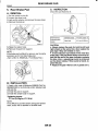
3. Steel Wheel
A: REMOVAL
1) Apply the parking brake, and position select lever to “P” or “LOW”.
2) Set the shop jacks or a lift to the specified point,
and support the vehicle with its wheels slightly contacting the floor.
3) Loosen the wheel nuts.
4) Raise the vehicle until its wheels take off the
ground using a jack or a lift.
5) Remove the wheel nuts and wheels.
NOTE:
While removing the wheels, prevent hub bolts
from damage.
NOTE:
Place the wheels with their outer sides facing upward to prevent wheels from damage.
1) Deformation or damage on the rim can cause air
leakage. Check the rim flange for deformation,
crack or damage, and repair or replace as necessary.
2) Jack-up the vehicle until wheels clear the floor.
3) Slowly rotate the wheel to check rim “runout” using a dial gauge.
/
G4M029E
B: INSTALLATION
--I ) Attach the wheel to the hub by aligning the wheel
bolt hole with the hub bolt.
2) Temporarily attach the wheel nuts to the hub
bolts. (In the case of aluminum wheel, use SUBARU genuine wheel nut for aluminum wheel.)
3) Manually tighten the nuts making sure the wheel
hub hole is aligned correctly to the guide portion of
hub.
4) Tighten the wheel nuts in a diagonal selection to
the specified torque. Use a wheel nut wrench.
I-1.5 mm (0.059 in)
I
~
APP
Wheel nut tightening torque:
90 N.m (9. I kgf-m, 65.7 ff-lb)
CAUTION:
Tighten the wheel nuts in two or three steps
by gradually increasing the torque and working
diagonally, until the specified
torque is
reached. For drum brake models, excess tightening of wheel nuts may cause wheels to “judder”.
Do not depress the wrench with a foot; Always use both hands when tightening.
Make sure the bolt, nut and the nut seating
surface of the wheel are free from oils.
5) If a wheel is removed for replacement or for repair of a puncture, retighten the wheel nuts to the
specified torque after running 1,000 km (600
miles).
G4M0299
4) If the rim runout exceeds specifications, remove
the tire from rim and check runout while attaching
dial gauge to positions shown in figure.
5) If the measured runout still exceeds specifications, replace the wheel.
WT-5
I
ALUMINUM WHEEL
WHEEL AND TIRE SYSTEM
4. Aluminum Wheel
A: REMOVAL
Refer to Steel Wheel for removal procedure of a h minum wheels. <Ref. to WT-5, REMOVAL, Steel
Wheel.>
B: INSTALLATION
Refer to Steel Wheel for installation procedure of
aluminum wheels.cRef. to WT-5, INSTALLATION,
Steel Wheel.>
C: INSPECTION
Refer to Steel Wheel for inspection procedure of
aluminum wheels. <Ref. to WT-5, INSPECTION,
Steel Wheel.>
Rim runout:
I
Axial runout limit
I
Radial runout limit
1.O mm (0.039 in)
I
D: -CAUTION
Aluminum wheels are easily scratched. To maintain their appearance and safety, do the following:
1) Do not damage the aluminum wheels during removal, disassembly, installation, wheel balancing,
etc. After removing the aluminum wheels, place
them on a rubber mat, etc.
2) While the vehicle is being driven, be careful not
to ride over sharp obstacles or allow aluminum
wheels to contact the shoulder of the road.
3) When installing a tire chain, be sure to install it
properly not to have a slack; otherwise it may hit
the wheel while driving.
4) When washing the aluminum wheel, use neutral
synthetic detergent and water. Avoid using the
cleanser including abrasive, hard brushes or an
automatic car washer.
WT-6
I
WHEEL BALANCING
WHEEL AND TIRE SYSTEM
B: INSPECTION
5. Wheel Balancing
A: REPLACEMENT
1) Remove the balance weights.
2) Using the dynamic balancing, measure wheel
balance.
3) Select a weight close to the value measured by
dynamic balancing.
I
Balance weight part number
(For steel wheel)
I
I
723141300
723141310
723141320
723141330
723141340
723141350
723141360
723141370
723241380
723241580
723241590
I
I
c-
~
Weight
I
I
I
I
Balance weight part number
(For aluminum wheel)
23 14 1GA462
23141GA472
r I
I
I
10 g (0.35 02)
15 g (0.53 02)
20 g (0.71 02)
25 g (0.88 02)
30 g (1.06 02)
35 CI (1.23 oz)
I
I
40 g (1.41 02)
45 g (1.59 02)
50 g (1.76 02)
55 g (1.94 02)
60 g (2.12 02)
I
I
Weight
5 g (0.18 02).
10 a (0.35 02)
23141GA492
23141GA502
23141GA512
23141GA522
23141GA532
23141GA542
23141GA552
I
I
I
20 CI (0.71 02)
25 g (0.88 02)
30 g (1.06 02)
35 g (1.23 02)
40 g (1.41 02)
45 g (1.59 02)
50 Q (1.76 02)
I
-
I
55 g (1.94 02)
60 g (2.12 02)
I
23141GA572
1) Proper wheel balance may be lost if the tire is repaired or if it wears. Check the tire for dynamic balance, and repair as necessary.
2) To check for dynamic balance, use a dynamic
balancer. Drive in the balance weight on both the
top and rear sides of the rim.
3) Some types of balancer can cause damage to
the wheel. Use an appropriate balancer when adjusting the wheel balance.
4) Use genuine balance weights.
CAUTION:
55 g (1.94 02) weight used with aluminum
wheel is not available.
Balance weights are available for use with
any of 14- to 16-inch wheels.
I
I
B4M0053B
(1) Weight for aluminum wheel
(2) Weight for steel wheel
Service limit: A
Weight for steel wheel;
2.16 mm (0.085 in)
Weight for aluminum wheel;
4.5 mm (0.177 in)
WT-7
I
“T-TYPE” TIRE
WHEEL AND TIRE SYSTEM
6. “T-type” Tire
A: NOTE
“T-type” tire for temporary use is prepared as a
spare tire.
CAUTION:
Do not use a tire chain with the “T-type” tire.
Because of the smaller tire size, a tire chain will
not fit properly and will result in damage to the
vehicle and the tire.
Do not drive at a speed greater than 80 km/h
(50 MPH).
Drive as slowly as possible and avoid passing over bumps.
B: REPLACEMENT
Refer to Removal and Installation of Steel Wheel
for removaVinstallation of “T-type” tires. <Ref. to
WT-5, Steel Wheel.>
CAUTION:
Tiepiace with a conventional tire as soon as
possible since the “T-type” tire is only for temporary use.
C: INSPECTION
1) Check the tire inflation pressure.
Specification:
420 kPa (4.2 kg/cn?, 60 psi)
2) Take the stones, glass, nails, etc. out of the tread
groove.
3) Check the tires for deformation, cracks, partial
wear, or wear.
CAUTION:
Replace the tire with a new one.
WT-8
I
FULL WHEEL CAP
WHEEL AND TIRE SYSTEM
7. Full Wheel Cap
A: REMOVAL
Pry off the full wheel cap with a wheel cap remover
inserted between openings in the cap.
B: INSTALLATION
Align the valve hole in the wheel cap with the valve
on the wheel and secure the wheel cap by tapping
four
*.- . points by hand.
C: INSPECTION
1) Check the wheels for missing wheel caps.
2) Check the pawls of wheel caps for damage or
bend.
3) Check the wheel caps for cracks.
WT-9
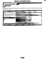
3
GENERAL DIAGNOSTICS TABLE
WHEEL AND TIRE SYSTEM
8. General Diagnostics Table
A: INSPECTION
II
Front wheel shimmy
Abnormal tire wear
Sways/pitches
Wander/pulls
I
I
I
Worn or improperly inflated of tire.
I Replace
Wheel is out of balance.
Improperly inflated of tire.
Worn or improperly inflated of tire.
Worn or improperly inflated of tire.
I Adjustment
I Replace
WT-10
Replace
Replace
I
I
I
E
DIFFERENTIALS
Dl
~~~~~~~~
1.
2.
3.
4.
5.
6.
7.
8.
~
Page
General Description .... ..................................................................... ...........2
Differential Gear Oil ...................................................................................
17
Front Differential........................................................................................ 18
Rear Differential ........................................................................................
19
Rear Differential Front Oil Seal ......................................
.... .......................35
Rear Differential Side Oil Seal .................................................................. 37
Rear Differential Member ..........................................................................
40
General Diagnostic Table .......................................................................... 41
I
GENERAL DESCRIPTION
DIFFERENTIALS
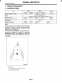
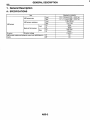
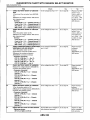
1. General Description
A: SPECIFICATIONS
II
I
I
Non-Turbo
Turbo
MODEL
Waaon
Type of gear
Gear ratio (Number of gear
teeth)
Sedan
Waaon
Sedan
MT
AT
3.545 (39/11)
4.1 11 (37/9)
I
Hypoid gear
3.900 (39/10)
4.1 11 (37/9)
Oil capacity
0.8
0
Rear differential gear oil
4.444 (40/9)
(0.8 US qt, 0.7 Imp qt)
GL-5
causes the drive line and tires to "drag" or emit
abnormal noise when AWD is selected.
I \
ITEM
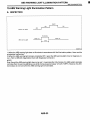
Rear differential gear oil
API Classification
I
tiL-5
SAE Viscosity No. and Application Temperature
("C) -30 -26 -15 -5 0
15 25 30
( O F ) -22 -15
5 23 32
59 77 86
I
I
I
I
1-2
I
L
'
I
75W-90
I
I
f=
I
I
I
I
H3M1272A
DROOOI
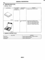
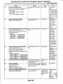
1. SERVICE DATA
Front and rear bearing preload at companion New bearing
flange bolt hole N (kgf, Ib)
Used bearing
Side aear backlash mm (in)
I Side bearina standard width mm (in)
I Crown gear to drive pinion backlash mm (in)
I Crown gear runout on its back surface mm (in)
I
I
I
19.6 - 28.4 (2.0 - 2.9, 4.4 - 6.4)
8.34-16.67(0.85-1.7,
1.87-3.75)
0.10 - 0.20 (0.0039 - 0.0079)
20.00 (0.7874)
0.10 - 0.20 (0.0039 - 0.0079)
Less than 0.05 (0.0020)
2. ADJUSTING PARTS
New bearing
Front and rear bearing preload at companion flange bolt hole
Used bearing
I
I
Preload adjusting spacer
Part No.
383695201
383695202
383695203
383695204
383695205
383695206
DI-2
I
I
19.6 - 28.4 N
(2.0 - 2.9 kgf, 4.4 - 6.4 Ib)
8.34 - 16.67 N
(0.85 - 1.7 kgf, 1.87 - 3.75 Ib)
Lenath
56.2 mm (2.213 in)
56.4 mm (2.220 in)
56.6 mm (2.228 in)
56.8 mm (2.236 in)
57.0 mm (2.244 in)
57.2 mm (2.252 in)
I
I
I
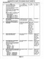
GENERAL DESCRIPTION
DIFFERENTIALS
Length
2.59 mm (0.1020 in)
2.57 mm (0.1012 in)
I
Part No.
383705200
383715200
383725200
t
t
3.33 mm (0.131 1 in)
383575200
383585200
3.36 mm (0.1323 in)
3.39 mm (0.1335 in)
383595200
3.42 mm (0.1346 in)
383605200
3.45 mm (0.1358 in)
383615200
3.48 mm (0.1370 in)
383625200
383635200
3.51 mm (0.1382 in)
3.54 mm (0.1394 in)
383645200
383655200
3.57 mm (0.1406 in)
3.60 mm (0.141 7 in)
383665200
3.63
mm (0.1429 in)
383675200
383685200
3.66 mm (0.1441 in)
0.1 - 0.2 mm (0.0039 - 0.0079 in)
Part No.
Thickness
I
II 0.75 - 0.80 mm (0.0295 - 0.0315 in)
383445201
383445202
I 0.80 - 0.85 mm (0.0315 - 0.0335 in)
I
2.55 mm (0.1004 in)
I
I Preload adjusting washer
..
Pinion height adjusting shim
Side gear backlash
Side gear thrust washer
(Non-Turbo model)
Side bearina standard width
-
I Side bearing retainer shim
-1
I
&own gear to drive pinion backlash
Crown gear runout on its back sunface
~
Part No.
383475201
383475202
383475203
383475204
383475205
Limit
DI-3
I
I
20.00 mm (0.7874 in)
Thickness
0.20 mm (0.0079 in)
0.25 mm (0.0098 in)
0.30 mm (0.0118 in)
0.40 mm (0.0157 in)
0.50 mm (0.0197 in)
0.10 - 0.20 mm (0.0039 - 0.0079 in)
0.05 mm (0.0020 in)
I
I
I
I
GENERAL DESCRIPTION
DIFFERENTIALS
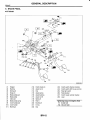
B: COMPONENT
1. REAR DIFFERENTIAL WITHOUT LSD
Pinion crown gear set
Pinion height adjusting washer
Rear bearing
Bearing preload adjusting spacer
Bearing preload adjusting washer
Differentialcarrier
Front bearing
Spacer
Pilot bearing
(IO) Front oil seal
(11) Companion flange
(12) Self-locking nut
(1)
(2)
(3)
(4)
(5)
(6)
.,
(7)
(8)
(9)
(13) Side bearing
(14) O-ring
(15) Side bearing retainer shim
(16) Side bearing retainer
(17) Side oil seal
(18)
. , Side aear
.. thrust washer
(19) Side gear
(20) Pinion mate gear
(21) Pinion mate gear washer
(22) Pinion shaft lock pin
(23) Circlip
(24) Pinion mate shaft
DI-4
(25) Air breather cap
(26) Stud bolt
(27) Oil filler plug
(28) Oil drain plug
(29) Rear cover
(301 Differentialcase
Tightening torque: N-m (kgf-m, ft-lb)
T1: 10.3 (1.05, 7.6)
T2: 29.4 (3.00,21.7)
T3: 49.0 (5.0, 36.2)
T4: 103.0 (10.50, 75.9)
T5: 181.4 (18.50, 133.8)
\
I
I
GENERAL DESCRIPTION
DIFFERENTIALS
2. REAR DIFFERENTIAL WITH LSD
(1)
Pinion crown gear set
(2) Pinion height adjusting shim
Rear bearing
Bearing preload adjusting spacer
Bearing preload adjusting washer
Differentialcarrier
Front bearing
Collar
Pilot bearing
Front oil seal
Companion flange
(12)
(13)
Self-locking nut
Side bearing
O-ring
Side bearing retainer shim
Side bearing retainer
Side oil seal
Gasket
Differential case
Rear cover
Air breather cap
Stud bolt
DI-5
(23)
(24)
Oil filler plug
Oil drain plug
Tightening torque: N.m (kgf-m, ft-lb)
T1: 10.3 (1.05, 7.6)
TZ: 29.4 (3.00,21.7)
T3: 49.0 (5.00, 36.2)
T4: 103.0 (10.50, 75.9)
T5: 181.4 (18.50, 133.8)
I
I
GENERAL DESCRIPTION
DIFFERENTIALS
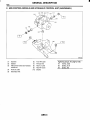
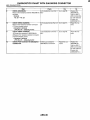
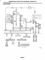
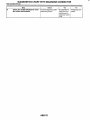
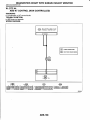
3. REAR DIFFERENTIAL MOUNTING SYSTEM
DR0002
(1)
(2)
(3)
(4)
(5)
Differentialfront member
Plate
Crossmember
Differential rear member
Differential mount lower bracket
(TURBO model)
(6)
Differential mount lower bracket
(Non-turbo model)
(7)
(8)
(9)
(10 )
Stopper
Dynamic damper
Differential mount bracket
Differential mount front cover
DI-6
Tightening torque: N-m (kgf-m, ft-I&)
T1: 20(2.0, 14.5)
T2: 33 (3.4, 24.3)
T3: 65 (6.6, 47.9)
T4: 70 (7.1, 51.6)
T5: 90 (9.2, 66.4)
T6: 100 (10.2, 73.8)
GENERAL DESCRIPTION
DIFFERENTIALS
C: CAUTION
Wear working clothing, including a cap, protective goggles, and protective shoes during operation.
Remove contamination including dirt and corrosion before removal, installation or disassembly.
Keep the disassembled parts in order and protect them from dust or dirt.
Before removal, installation or disassembly, be
sure to clarify the failure. Avoid unnecessary removal, installation, disassembly, and replacement.
Be careful not to burn your hands, because each
part on the vehicle is hot after running.
Use SUBARU genuine gear oil, grease etc. or
the equivalent. Do not mix gear oil, grease etc. with
that of another grade or from other manufacturers.
Be sure to tighten fasteners including bolts and
nuts to the specified torque.
Place shop jacks or safety stands at the specified
points.
--a- Apply gear oil onto sliding or revolution surfaces
before installation.
Before installing O-rings or snap rings, apply sufficient amount of gear oil to avoid damage and deformation.
Before securing a part on a vice, place cushioning material such as wood blocks, aluminum plate,
or shop cloth between the part and the vice.
Avoid damaging the mating face of the case.
DI-7
GENERAL DESCRIPTION
DIFFERENTIALS
D: PREPARATION TOOL
1. SPECIAL TOOLS
ILLUSTRATION
TOOL NUMBER
398477701
DESCRIPTION
HANDLE
REMARKS
Used for installing front and rear bearing cone.
398477702
DRIFT
Used for press-fitting the bearing cone of differential carrier (rear).
398217700
ATTACHMENT SET
Stand for rear differential carrier disassembly
and assembly.
498447120
DRIFT
Used for installing front oil seal.
B3M1893
B3M1894
B3M1895
B3M1896
DI-8
I
GENERAL DESCRIPTION
98427200
DESCRIPTION
LANGE WRENCH
IEMARKS
k e d for stopping rotation of companion flange
vhen loosening and tightening self-lock nut.
I98467700
)RIFT
Jsed for removing pinion, pilot bearing and front
iearing cone.
a7801 04
VEIGHT
Used for installing front bearing cone, pilot bearing companion flange.
899580100
NSTALLER
Used for press-fittingthe front bearing cone, pilo
bearing.
TOOL NUMBER
ILLUSTRATION
DIFFERENTIALS
B3M1897
B3M189e
~
B3M189(
B3M190
DI-9
GENERAL DESCRIPTION
DIFFERENTIALS
ILLUSTRATION
TOOL NUMBER
899904100
DESCRIPTION
STRAIGHT PIN
REMOVER
REMARKS
Used for driving out differential pinion shaft lock
Din.
498247001
MAGNET BASE
1 Used for measuring backlash between side
jear and pinion, and hypoid gear.
1 Used with DIAL GAUGE (498247100).
498247100
DIAL GAUGE
1 Used for measurng backlash between side
gear and pinion, and hypoid gear.
1 Used with MAGNET BASE (498247001).
398507704
BLOCK
Jsed for adjusting pinion height and preload.
B3M1901
B3M1902
03M1903
B3M1904
DI-I 0
I
I
GENERAL DESCRIPTION
DIFFERENTIALS
%98177700
DESCRIPTION
VSTALLER
3EMARKS
Used for installing rear bearing cone.
398457700
UTACHMENT
I
398477703
]RIFT2
1
398437700
DRIFT
TOOL NUMBER
ILLUSTRATION
3
B3M1905
Used for removing side bearing retainer.
6=:p
B3M1906
Used for press-fitting the bearing race (rear) of
differential carrier.
B3M190i
B3M1901
DI-11
Used for installing side oil seal.
GENERAL DESCRIPTION
DIFFERENTIALS
I
I
ILLUSTRATION
TOOL NUMBER
398507702
DESCRIPTION
DUMMY SHAFT
REMARKS
Used for adjusting pinion height and preload.
398507703
3UMMY COLLAR
Used for adjusting pinion height and preload.
39851 7700
3EPLACER
Used for removing rear bearing cone.
398487700
)RIFT
B3M1910
DI-I 2
1
Used for press-fitting the side bearing cone.
I
I
GENERAL DESCRIPTION
DIFFERENTIALS
ILLUSTRATION
TOOL NUMBER
398507701
DESCRIPTION
DIFFERENTIAL
CARRIER GAUGE
398527700
PULLEY ASSY
399527700
PULLER SET
REMARKS
Used for adjusting pinion height.
B3M1913
Used for removing front oil seal.
Used for removing side bearing cup. (T-type)
B3M1914
Used for extracting side bearing cone.
(1)BOLT (899521412)
(2)PULLER (399527702)
(3)HOLDER (399527703)
(4)ADAPTER (398497701)
(5)BOLT (899520107)
(6)NUT (021008000)
B3M1915A
398227700
WEIGHT
B3M1916
DI-I 3
.
Used for installing side bearing.
GENERAL DESCRIPTION
DIFFERENTIALS
I
ILLUSTRATION
TOOL NUMBER
28099PA090
DESCRIPTION
REMARKS
Used for installing rear drive shaft into rear difOIL SEAL PROTECTOR
ferential.
For protecting oil seal.
398237700
GAUGE
B3M1917
I------
Used for installing side bearing.
B3M1918
I
28099PA100
DRIVE SHAFT
REMOVER
399703602
WLLEY ASSY
B3M1930
DI-I 4
Used for removing rear drive shaft from rear
differential.
Used for removing companion flange
I
GENERAL DESCRIPTION
TOOL NUMBER
399874100
ILLUSTRATION
DESCRIPTION
INSTALLER
B3M193
DI-I 5
I
DIFFERENTIALS
3EMARKS
Used for installing companion flange.
1
GENERAL DESCRIPTION
DIFFERENTIALS
2. GENERAL PURPOSE TOOLS
I TOOL NAME
I Transmission jack
Puller
Thickness gauge
I REMARKS
1 Used for assembly/disassembly of rear differential.
Used for removal of side bearing retainer.
Used for measuring clearance.
DI-16
I
I
I
1
DIFFERENTIAL GEAR OIL
DIFFERENTIALS
2. Differential Gear Oil
A: INSPECTION
1) Take out the filler plug, and replace gear oil if it is
contaminated or deteriorated. <Ref. to DI-17, REPLACEMENT, Differential Gear Oil.>
2) Check gear oil level is up to the bottom part of filler bolt. If the level is low, refill up to the bottom of
filler bolt.
1
DUO017
.
Oil capacity:
0.8 Q (0.8 US qf, 0.7 Imp qt)
1
I
r-
5 ) Fill differential carrier with gear oil to the upper
plug level.
CAUTION:
Carefully refill oil while watching the level. Excess or insufficient oil must be avoided.
I
I
. . ,
.
.
.
,
I
(A) Filler plug
( 6 ) Drain plug
(A) Filler plug
( 6 ) Drain plug
B: REPLACEMENT
1) Disconnect the ground terminal from battery.
2) Jack-up the vehicle and support it with sturdy
racks.
3) Remove the oil drain plug and filler plug, and
drain the gear oil.
6) Install the filler plug.
NOTE:
Apply fluid packing to the filler plug.
Fluid packing:
THREE BOND 1105 or equivalent
Tightening torque:
49.0 N.m (5.0 kgf-m, 36.2 ff-lb)
CAUTION:
Be careful not to burn your hands, because
gear oil becomes extremely hot after running.
(A) Filler plug
(B) Drain plug
4) Tighten the oil drain plug.
NOTE:
Apply fluid packing to the drain plug.
Fluid packing:
THREE BOND I105 or equivalent
Tightening torque:
49.0 N.m (5.0 kgf-m, 36.2 ff-lb)
DI-17
I
FRONT DIFFERENTIAL
DIFFERENTIALS
3. Front Differential
A: NOTE
1. AT MODEL
Refer to AUTOMATIC TRANSMISSION in separate publication “AUTOMATIC TRANSMISSION”
for Front Differential. <Pub. No. G0853ZE>
2. MTMODEL
For front differential of manual transmission, refer
to “MT” section. <Ref. to MT-71, Front Differential
Assembly.>
DI-18
I
REAR DIFFERENTIAL
DIFFERENTIALS
4. Rear Differential
A: REMOVAL
1) Set the vehicle on the lift.
2 ) Disconnect the ground terminal from battery.
3) Move the select lever or gear shift lever to “N”.
4) Release the parking brake.
5) Loosen the wheel nuts.
6) Jack-up the vehicle and support it with sturdy
racks.
7) Remove the wheels.
8) Remove the rear exhaust pipe and muffler.
Non-turbo model:
<Ref. to EX(S0HC)-9, REMOVAL, Rear Exhaust
Pipe.> and <Ref. to EX(S0HC)-11, REMOVAL,
Muffler.>
Turbo model:
<Ref. to EX(D0HC TURBO)-13, REMOVAL, Rear
Exhaust
PiDe.> and <Ref. to EX(D0HC TURBO)14, REMOVAL, Muffler.>
9) Remove the rear differential protector. (If
equipped)
10) Remove the front cover of rear differential
mount.
14) Remove the DOJ of rear drive shaft from rear
differential using ST. <Ref. to DI-37, REPLACEMENT, Rear Differential Side Oil Seal.>
ST 28099PA100 DRIVE SHAFT REMOVER
(A) Bolt
15) Secure the rear drive shaft to rear crossmember using wire.
r
.
S3M0500
16) Remove the lower differential bracket.
11) Remove the propeller shaft. <Ref. to DS-14,
REMOVAL, Propeller Shaft.>
12) Remove the heat shield cover.
13) Remove the clamps and bracket of parking
brake cable.
0
S3M0529
17) Support the rear differential with transmission
jack.
DI-I 9
I
REAR DIFFERENTIAL
DIFFERENTIALS
18) Remove the self-locking nuts and bolts.
22) Remove the rear differential from front member, and remove rear member.
19) Remove the bolts which secure rear differential
front member to body.
Loosen bolt A first, then remove bolts B.
NOTE:
Support the front member with the use of a helper
to prevent it from dropping.
c-
-
\
\
'
'B3M0657C
1
(A) Bolt A
(B) Bolt B
G3M1030
B: INSTALLATION
To install, reverse the removal sequence.
1) Install the air breather cap tapping with a plastic
hammer.
CAUTION:
Be sure to install a new air breather cap.
2) Position the front member on body by passing it
under parking brake cable and securing to rear differential.
NOTE:
When installing the rear differential front member,
do not confuse the installation sequence of the upper and lower stoppers.
3) Install the DOJ of drive shaft into rear differential.<Ref. to DI-37, REPLACEMENT, Rear Differential Side Oil Seal.>
ST 28099PA090 SIDE OIL SEAL PROTECTOR
20) Remove bolt A.
21) While slowly lowering the transmission jack,
move rear differential forward and remove front
member and rear differential from body.
. .
I
' G3M1029
4) Install in the reverse order of removal.
5 ) After installation, fill the differential carrier with
gear oil to the filler plug level. <Ref. to DI-17, Differential Gear Oil.>
DI-20
REAR DIFFERENTIAL
C: DISASSEMBLY
To detect the real cause of trouble, inspect the following items before disassembling.
Tooth contact of crown gear and pinion, and
backlash
Runout of crown gear at its back surface
Turning resistance of drive pinion
1) Set the ST on vise and install the differential assembly to ST.
ST 398217700
ATTACHMENT
DIFFERENTIALS
4) Remove the rear cover by loosening retaining
bolts.
I
I
(A) Rear cover
(B) Differential carrier
I
ST
G3M1031
1
2) Drain the gear oil by removing plug.
3) Remove the air breather cap.
NOTE:
Do not attempt to replace the air breather cap unless necessary.
5) Make right and left side bearing retainers in order to identify them at reassembly. Remove the
side bearing retainer attaching bolts, set the ST to
differential case, and extract right and left side
bearing retainers with a puller.
CAUTION:
Each shim, which is installed to adjust the side
bearing preload, should be kept together with
its mating retainer.
ST 398457700
ATTACHMENT
)
S3M0530A
(A) Air breather cap
(B) Rear cover
6) Pull out the differential case assembly from differential carrier.
CAUTION:
Be careful not to hit the teeth against the case.
S3M0533
DI-21
I
I
REAR DIFFERENTIAL
DIFFERENTIALS
7) When replacing the side bearing, pull the bearing cup from side bearing retainer using ST.
ST 398527700
PULLER ASSY
,
10) Drive out the pinion shaft lock pin from crown
gear side. (Without LSD)
NOTE:
The lock pin is staked at the pin hole end on the differential carrier; do not drive it out forcibly before
unstaking it.
ST 899904100
STRAIGHT PIN REMOVER
S3M05341:
8) Extract the bearing cone with ST.
CAUTION:
Do not attempt to disassemble the parts unless
necessary.
NOTE:
Set the puller so that its claws catch the edge of
+he bearing cone.
Never mix up the right and left hand bearing races and cones.
ST 398527700
PULLER SET
11) Draw out the pinion mate shaft and remove pinion mate gears, side gears and thrust washers.
(Without LSD)
NOTE:
The gears as well as thrust washers should be
marked or kept separated right and left, and front
and rear.
(C)
9) Remove the crown gear by loosening crown
gear bolts.
CAUTION:
Further disassembling is not allowed.
S3M0509
DI-22
S3M051OP
(A) Sidegear
(B) Pinion mate gear
(C) Thrust washer
(D) Differential case
(E) Pinion mate shaft
I
REAR DIFFERENTIAL
12) Hold the companion flange with ST and remove
drive pinion nut.
ST 498427200
FLANGE WRENCH
I
DIFFERENTIALS
15) Remove the rear bearing cone from drive pinion by supporting cone with ST.
NOTE:
Place the replacer so that its center-recessed side
faces the pinion gear.
ST 398517700
REPLACER
13) Extract the companion flange with a puller.
S3MOS
16) Remove the front oil seal from differential carrier using ST.
ST 398527700
PULLER ASSY
14) Press the end of drive pinion shaft and extract it
together with rear bearing cone, preload adjusting
spacer and washer.
NOTE:
Hold the drive pinion so as not to drop it.
ST 398467700
DRIFT
S3M0513
17) Remove the pilot bearing together with front
bearing cone using ST.
ST 398467700
DRIFT
G3M0078
S3M0514A
(A) Pinion bearing
(B) Front bearing
(C) Rear bearing cup
DI-23
I
I
REAR DIFFERENTIAL
DIFFERENTIALS
18) When replacing the bearings, tap front bearing
cup and rear bearing cup in this order out of case
by using a brass bar.
(A) 2 cutouts along diagonal lines
(6) Tap alternately with brass bar.
D: ASSEMBLY
1) Precautions for assembling:
Assemble in the reverse order of disassembling.
Check and adjust each part during assembly.
Keep the shims and washers in order, so that
they are not misinstalled.
Thoroughly clean the surfaces on which the
shims, washers and bearings are to be installed.
Apply gear oil when installing the bearings and
thrust washers.
Be careful not to mix up the right and left hand
races of the bearings.
Replace the oil seal with a new one at every disassembly. Apply chassis grease between the lips
when installing the oil seal.
c.
2) Adjusting preload for front and rear bearings:
Adjust the bearing preload with spacer and washer
between front and rear bearings. Pinion height adjusting washer are not affected by this adjustment.
The adjustment must be carried out without oil seal
inserted.
(1) Press the rear bearing race into differential
carrier with STI and ST2.
ST1 398477701 HANDLE
ST2 398477703 DRIFT 2
m
G3M1037
(2) Insert the ST1 into carrier with pinion height
adjusting washer and rear bearing cone fitted
onto it.
CAUTION:
Re-use the used washer if not deformed.
Use a new rear bearing cone.
DI-24
I
REAR DIFFERENTIAL
DIFFERENTIALS
(3) Then install the preload adjusting spacer
and washer, front bearing cone, ST2, companion flange, and washer and drive pinion nut.
ST1 398507702 DUMMY SHAFT
ST2 398507703 DUMMY COLLAR
Front and rear bearing preload
For new bearing:
19.6- 28.4N (2.0- 2.9kgf, 4.4- 6.4Ib)
at companion flange bolt hole
For used bearing:
8.34- 16.67N (0.85- 1.7 kgf, 1.87- 3.75Ib)
at cotmanion flanae bolt hole
S3M0516A
(A) Pinion height adjusting shim
(8) Preload adjusting spacer
(C) Preload adjusting washer
---
1
(4) Turn the STI with hand to make it seated,
and tighten the drive pinion nut while measuring
the preload with spring balance. Select the preload adjusting washer and spacer so that the
specified preload is obtained when nut is tightened to the specified torque.
CAUTION:
Use a new lock nut.
NOTE:
Be careful not to give excessive preload.
When tightening the drive pinion nut, lock ST1
with ST2 as shown in the figure.
ST1 398507704 BLOCK
ST2 398507702 DUMMY SHAFT
1
I
383705200
383715200
383725200
383735200
I
[
I
1
Thickyiy mm
. .
2.59 (0.1020)
2.57(0.1012)
2.55(0.1004)
2.53 10.0996)
I
383775200
383785200
383795200
383805200
383815200
383825200
383835200
383845200
rI
1
I
I
2.45 (0.0965)
2.43 (0.0957)
2.41 (0.0949)
2.39(0.0941)
2.37 (0.0933)
2.35(0.0925)
2.33(0.0917)
2.31 (0.0909)
Part No.
Preload adjusting
spacer
G3M1038
DI-25
II
I
383755200
’reload adjusting
Masher
Tightening torque:
181 N.m (18.5 kgf-m, 134 ft-lb)
U
Part NO.
383695202
383695203
383695204
383695205
383695206
1
I
56.4(2.2201
56.6(2.228)
56.8 (2.236)
57.0(2.244)
57.2 (2.252)
1
f
I
I
I
REAR DIFFERENTIAL
DIFFERENTIALS
3) Adjusting drive pinion height:
Adjust the drive pinion height with shim installed
between rear bearing cone and the back of pinion
gear.
(1) Install STl, ST2 and ST3, as shown in the
figure, and apply the specified preload on the
bearings.
Front and rear bearing preload
For new bearing:
19.6 - 28.4 N (2.0 - 2.9 kgf, 4.4 - 6.4 Ib)
at companion flange bolt hole
For used bearing:
8.34-l6.67N(0.85-l1.7kgf, 1.87-3.75Ib)
at companion flange bolt hole
Adjusting preload for front and rear bearings:
NOTE:
At this time, install a pinion height adjusting shim
which is temporarily selected or the same as that
used before. Measure and record the thickness.
ST1
398507702 DUMMY SHAFT
.
ST2 398507701 DIFFERENTIAL CARRIER
GAUGE
ST3 398507703 DUMMY COLLAR
c-
-I
(2) Measure the clearance N between the end
of ST2 and the end surface of STI by using a
thickness gauge.
NOTE:
Make sure there is no clearance between the case
and ST2.
ST1 398507702 DUMMY SHAFT
ST2 398507701 DIFFERENTIAL CARRIER
GAUGE
H3M1309B
(3) Obtain the thickness of pinion height adjusting shim to be inserted from the following formula, and replace the temporarily installed shim
with this one.
T = To + N - (H x 0.01) - 0.20 mm (0.0079 in)
NOTE:
Use copies of this page.
T
Thickness of shim temporarily inserted
mm (in)
Thickness
of
pinion
height
adjusting
To
I shim
mm (in) I
N
Reading of thickness gauge mm (in)
H
I Figure marked on drive pinion head I
Memo:
I
S3M0518B
I
(A) Pinion height adjusting shim
(Example of calculation)
To = 2.20 + 1.20 = 3.40 mm
N = 0.23 mm H = + 1,
T = 3.40 + 0.23 - 0.01 - 0.20 = 3.42
Result: Thickness = 3.42 mm
Therefore use the shim 383605200.
DI-26
I
REAR DIFFERENTIAL
DIFFERENTIALS
I
i
Pinion height adjusting shim
383495200
c-
-
I
383525200
3.15 (0.1240)
3.18 (0.1 252)
383545200
383555200
383565200
383575200
383585200
383595200
383605200
383615200
383625200
383635200
383645200
383655200
383665200
383675200
383685200
3.24 (0.1276)
3.27 (0.1287)
3.30 (0.1299)
3.33 (0.1311)
3.36 (0.1323)
3.39 (0.1335)
3.42 (0.1346)
3.45 (0.1358)
3.48 (0.1370)
3.51 (0.1382)
3.54 (0.1394)
3.57 (0.1 406)
3.60 (0.1417)
3.63 (0.1429)
3.66 (0.1441)
ST 398177700
5) Insert the drive pinion into differential carrier, install the previously selected bearing preload adjusting spacer and washer.
(A)
(B)
(C)
(D)
Drive pinion
Bearing adjusting spacer
Washer
Differential carrier
6) Press-fit the front bearing cone into case with
ST1, ST2 and ST3.
ST1 398507703 DUMMY COLLAR
ST2 399780104 WEIGHT
ST3 899580100 INSTALLER
INSTALLER
S3M0519A
7) Insert the spacer, then press-fit pilot bearing with
ST1 and ST2.
ST1 399780104 WEIGHT
ST2 899580100 INSTALLER
DI-27
I
REAR DIFFERENTIAL
DIFFERENTIALS
8) Fit a new oil seal with ST.
NOTE:
Press-fit until end of oil seal is 1 mm (0.04 in) inward from end of carrier.
Apply grease between the oil seal lips.
DRIFT
ST 498447120
11) Assembling differential case:
Install the side gears and pinion mate gears, with
their thrust washers and pinion mate shaft, into differential case. (Without LSD)
CAUTION:
Apply gear oil on both sides of the washer
and on the side gear shaft before installing.
Insert the pinion mate shaft into the differential case by aligning the lock pin holes.
9) Press-fit the companion flange with ST1 and
ST2.
GAUTION:
Be careful not to damage the bearing.
ST1 899874100 INSTALLER
ST2 399780104 WEIGHT
G3M0089
(1) Measure the side gear backlash.
Side gear back clearance:
0.10 - 0.20 mm (0.0039 - 0.0079 in)
S3M0521A
10) Install the self-locking nut. Then tighten it with
ST.
ST 498427200
FLANGE WRENCH
Tightening torque:
181 N-m (18.5 kgf-m, 134 fWb)
DI-28
1
REAR DIFFERENTIAL
DIFFERENTIALS
Thickness mm (in)
Part No.
I
383445201
383445202
383445203
I
0.75- 0.80(0.0295- 0.0315)
0.80- 0.85(0.0315 - 0.0335)
0.85- 0.90(0.0335- 0.0354)
I
14) Adjusting the side bearing retainer shims:
(1) The driven gear backlash and side bearing
preload can be determined by the side bearing
retainer shim thickness.
(2) Installthe differential case assembly into differential carrier in the reverse order of disassembly.
(3) Install the side retainer shims and O-rings to
the left and right retainers from which they were
removed.
NOTE:
Replace the broken or cracked O-ring with a new
one.
Replace the broken or corroded side retainer
shim with a new one of same thickness.
Thickness mm (in)
Part No.
I
S3M0509
383475201
383475202
383475203
383475204
3a3475205
I
13) Press the side bearing
- cone onto differential
case with ST.
DRIFT
ST 398487700
w
(A) Arrow mark
01-29
I
0.20 (0.0079)
0.25(0.0098)
0.30(0.0118)
0.40(0.0157)
0.50(0.0197)
I
I
REAR DIFFERENTIAL
DIFFERENTIALS
15) Recheck the crown gear-to-pinion backlash.
(5) Tighten the side bearing retainer bolts.
CAUTION:
Before tightening the two side bearing retainer
bolts, apply Lock Tite to bolt threads.
Backlash:
0.10 - 0.20 mm (0.0039 - 0.0079 in)
+Lock Tite:
THREE BOND 1 105 or equivalent
-
Tightening torque:
10.3 N.m (1.05 kgf-m, 7.6 ft-16)
G3M1047
16) Check the crown uear runout on its back surface, and make sure pinion and crown gear rotates
smoothIy .
Limit of runout:
Less than 0.05 mm (0.0020 in)
S3M0173
(6) Measure the crown gear-to-drive pinion
backlash. Set the magnet base on differential
carrier. Align the contact point of dial gauge with
tooth face of crown gear, and move crown gear
while holding drive pinion still. Read the value indicated on dial gauge.
Backlash:
0.10 - 0.20 mm (0.0039 - 0.0079 in)
1
G3M1047
(7) At the same time, measure the turning resistance of drive pinion. Compared with the resistance when differential case is not installed, if
the increase of the resistance is not within the
specified range, readjust side bearing retainer
shims.
1
4
S3M0525
17) Checking and adjusting the tooth contact of
crown gear:
(1) Apply an even coat of red lead on both sides
of three or four teeth on the the crown gear.
Check the contact pattern after rotating the
crown gear several revolutions back and forth
until a definite contact pattern appears on the
crown gear.
(2) When the contact pattern is incorrect, readjust according to the instructions given in
“TOOTH CONTACT PATTERN”.
NOTE:
Be sure to wipe off red lead completely after adjustment is completed.
Turning resistance increase:
2 . 9 - l 0 . 8 N ( 0 . 3 - l 1 . 1 kgf,O.7-2.4Ib)
DI-30
I
REAR DIFFERENTIAL
DIFFERENTIALS
18) If proper tooth contact is not obtained, once
again adjust the drive pinion height changing RH
and LH side bearing retainer shims and the hypoid
gear
backlash.
(1) Drive pinion height
STl 398507702 DUMMY SHAFT
ST2 398507701 DIFFERENTIAL CARRIER
GAUGE
Where:
T = Thickness of pinion height adjusting shim
(">
To = Thickness of shim temDorarilv inserted
N = Reading of thickness gauge (mm)
H = Figure marked on drive pinion head
(2) Hyp6id gear backlash
Backlash:
0.10
0.20 mm (0.0039 - 0.0079 in)
-
H3M13098
T = To + N - (H x 0.01) - 0.20 (mm)
G3M104i
)
Condition
Correct tooth contact
Tooth contact pattern slightly shifted
towards toe under no load rotation.
(When loaded, contact pattern moves
toward heel.)
TOOTH CONTACT PATTERN
Contact pattern
Heel side
-
Adjustment
G3M0098A
Face contact
Backlash is too large.
This may cause noise and chipping at
tooth ends.
-
G3M0098B
Flank contact
Backlash is too small.
This may cause noise and stepped wear
on surfaces.
-
G3M0098C
DI-31
Increase thickness of drive pinion height
adjusting shim in order to bring drive pinion closer to crown gear center.
V
G3M0098F
Reduce thickness of drive pinion height
adjusting shim in order to move drive pinion away from crown gear.
G3M0098G
I
I
REAR DIFFERENTIAL
DIFFERENTIALS
Condition
Toe contact
Contact area is small.
TOOTH CONTACT PATTERN
Contact pattern
rhis may cause chipping at toe ends.
Adjustment
Adjust as for flank contact.
I
I
G3M0098G
G3M0098D
Heel contact
Contact area is small.
rhis may cause chipping at heel ends.
Adjust as for face contact.
V
G3M0098E
I): Adjusting direction of drive pinion
: Adjusting direction of crown gear
DI-32
G3M0098F
REAR DIFFERENTIAL
DIFFERENTIALS
19) Install the rear cover and tighten bolts to specified torque.
CAUTION:
Securely connect the ground terminal of rear
differential temperature sensor.
Tightening torque:
29 N-m (3.0 kgf-m, 2 1.7 ff-lb)
1. SIDE GEAR BACKLASH
Using a dial gauge, check the backlash of the side
gear.
Side gear backlash:
0.1 - 0.2 mm (0.004 - 0.008 in)
If the side gear backlash is not within the specification, adjust clearance as specified by selecting side
gear thrust washer.
1934
E: INSPECTION
‘-Wash all the disassembled parts clean, and examine them for wear, damage or other defects. Repair
or replace defective parts as necessary.
1) Crown gear and drive pinion:
If abnormal tooth contact is evident, find out the
cause and adjust to give correct tooth contact at assembly. Replace the gear if excessively worn or incapable of adjustment.
If crack, score or seizure is evident, replace as a
set. Slight damage of tooth can be corrected by oil
stone or the like.
2) Side gear and pinion mate gear:
Replace if crack, score or other defects are evident on tooth surface.
Replace if thrust washer contacting surface is
worn or seized. Slight damage of the surface can
be corrected by oil stone or the like.
3) Bearing:
Replace if seizure, peeling, wear, rust, dragging
during rotation, abnormal noise or other defect is
evident.
4) Thrust washers of side gear and pinion mate
gear:
Replace if seizure, flaw, abnormal wear or other
defect is evident.
5) Oil seal:
Replace if deformed or damaged, and at every disassembling.
6) Differential carrier:
Replace if the bearing bores are worn or damaged.
7) Differential case:
Replace if its sliding surfaces are worn or cracked.
8) Companion flange:
Replace if the oil seal lip contacting surfaces have
flaws.
2. CROWN GEAR BACKLASH
Using a dial gauge, check the backlash of the
crown gear.
Crown gear backlash:
0.1 - 0.2 mm (0.004 - 0.008 in)
If the crown gear backlash is not within the specification, adjust the side bearing preload or repair if
necessary.
DI-33
I
G3M1047
I
REAR DIFFERENTIAL
DIFFERENTIALS
F: ADJUSTMENT
3. CROWN GEAR RUNOUT
Using a dial gauge, check the crown gear runout.
1. SIDE GEAR BACKLASH
Crown gear runout:
Less than 0.05 mm (0.0020 in)
If the crown gear runout exceeds 0.05 mm (0.0020
in), replace the crown gear.
Adjust the side gear backlash.
<Ref. to DI-24, ASSEMBLY, Rear Differential.>
2. CROWN GEAR BACKLASH
Adjust the crown gear backlash.
<Ref. to DI-24, ASSEMBLY, Rear Differential.>
3. TOOTH CONTACT BETWEEN CROWN
GEAR AND DRIVE PINION
Adjust the tooth contact between crown gear and
drive pinion gear.
<Ref. to DI-24, ASSEMBLY, Rear Differential.>
9
4. TOTAL PRELOAD
Adjust the side bearing shim.
<Ref. to DI-24, ASSEMBLY, Rear Differential.>
S3M0525
4. TOOTH CONTACT BETWEEN CROWN
GEAR AND DRIVE PINION
r.
Inspect the tooth contact between crown gear and
driven pinion. <Ref. to DI-24, ASSEMBLY, Rear
Differential.>
5. TOTAL PRELOAD
Using a gauge, check the turning resistance increase.
Total preload:
2.9-l0.8N.m(0.3-l1.1 kgf,O.7-2.4Ib)
If the increase of the resistance is not within the
specification, adjust the side bearing retainer
shims.
B3M 1935
DI-34
I
REAR DIFFERENTIAL FRONT OIL SEAL
DIFFERENTIALS
11) Extract the companion flange using ST.
ST 399703602
PULLEY ASSY
5. Rear Differential Front Oil
Seal
.
A: INSPECTION
Make sure that there is no oil leakage from front oil
seal.
If there is any oil leakage, replace the oil seal.
B: REPLACEMENT
1 ) Set the vehicle on the lift.
2) Disconnect the ground terminal from battery.
3) Move the select lever or gear shift lever to “N”.
4) Release the parking brake.
5) Remove the oil drain plug, and drain gear oil.
---
6448
12) Remove the oil seal using ST.
ST 499705401
PULLER ASSY
.
/
i:
DR0003
(A) Filler plug
(B) Drain plug
B3M1609B
13) Fit a new oil seal using ST
ST 498447120
DRIFT
6) Install the oil drain plug.
NOTE:
Apply fluid packing to drain plug.
Tightening torque:
49 N.m (5.0 kgf-m, 36.2 ft-lb)
7) Remove the rear exhaust pipe and muffler.
8) Remove the rear differential protector. (If
equipped)
9) Remove the propeller shaft from body. <Ref. to
DS-14, REMOVAL, Propeller Shaft.>
IO) Remove the self-locking nut while holding companion flange with ST.
ST 498427200
FLANGE WRENCH
I
/ /
\ \
G3M0037
14) Install the companion flange.
NOTE:
Use a plastic hammer to install companion flange.
G3M0034
DI-35
I
REAR DIFFERENTIAL FRONT OIL SEAL
DIFFERENTIALS
15) Tighten the self-locking nut within the specified
torque range so that the turning resistance of companion flange becomes the same as that before replacing oil seal.
ST 498427200
FLANGE WRENCH
NOTE:
Use a new self-locking nut.
Tightening torque:
181.4 N-m (18.50 kgf-m, 133.8 ff-lb)
r.
.
\ \
G3M0034
16) Reassembling procedure hereafter is the reverse of the disassembling.
17) Fill the differential carrier with gear oil to the filler plug level. <Ref. to DI-17, Differential Gear Oil.>
DI-36
1
REAR DIFFERENTIAL SIDE OIL SEAL
DIFFERENTIALS
6. Rear Differential Side Oil Seal
(3) Remove the ABS sensor cable clamp and
parking brake cable guide from the trailing link.
A: INSPECTION
Make sure that there is no oil leakage from side oil
seal.
If there is any oil leakage, replace the oil seal.
B: REPLACEMENT
1) Disconnect the ground terminal from battery.
2) Move the select lever or gear shift lever to “N”.
3) Release the parking brake.
4) Loosen both wheel nuts.
5 ) Jack-up the vehicle and support it with rigid
racks.
6) Remove the wheels.
7) Remove the rear exhaust pipe and muffler.
Non-turbo model:
<Ref. to EX(S0HC)-9, REMOVAL, Rear Exhaust
Pipe.> and <Ref. to EX(S0HC)-11, REMOVAL,
Muffler.>
Turbo model:
*<Ref. to EX(D0HC TURBO)-13, REMOVAL, Rear
Exhaust Pipe.> and <Ref. to EX(D0HC TURBO)14, REMOVAL, Muffler.>
8) Remove the DOJ of rear drive shaft from rear differential.
(1) Remove the ABS sensor cable clamp and
parking brake cable clamp from bracket.
(A) ABS sensor cable clamp
(B) Parking brake cable guide
(4) Remove the rear stabilizer link.
-
17
(5) Remove the bolts which secure the trailing
link to the housing.
(A) ABS sensor cable clamp
(B) Parking brake cable guide
\\
(2) Remove the ABS sensor cable clamp from
the trailing link.
DI-37
G3M0042
(6) Remove the bolts which secure the front
and rear lateral link to the rear housing.
I
REAR DIFFERENTIAL SIDE OIL SEAL
DIFFERENTIALS
(7) Remove the DOJ from the rear differential
by using ST.
CAUTION:
When removing the DOJ from the rear differential, fit ST to the bolts as shown in figure so as
not to damage the side bearing retainer.
ST 208099PA100 DRIVE SHAFT REMOVER
10) Remove the nut of protector.
PULLER ASSY
ST 398527700
G3M1023
11) Drive in a new side oil seal with ST.
CAUTION:
Apply chassis grease between the oil seal lips.
ST 398437700
DRIFT
I
1024
DR0006
(A) Bolt
12) Insert the DOJ into rear differential.
(1) Install the ST to rear differential.
ST 28099PA090 SIDE OIL SEAL PROTECTOR
,
9) Remove the rear drive shaft to rear crossmember using wire.
S3M050C
DI-38
I
1
REAR DIFFERENTIAL SIDE OIL SEAL
DIFFERENTIALS
_
_
_
~
~
(2) Install the spline shaft until the spline portion
is inside the side oil seal using ST.
ST 28099PA090 SIDE OIL SEAL PROTECTOR
(3) Remove ST.
ST 28099PA090 SIDE OIL SEAL PROTECTOR
13) Hereafter, reassemble in the reverse order of
disassembly.
-44)Fill differential carrier with gear oil to the filler
plug level. <Ref. to DI-17, Differential Gear Oil.>
DI-39
I
REAR DIFFERENTIAL MEMBER
DIFFERENTIALS
B: INSTALLATION
7. Rear Differential Member
A: REMOVAL
1) Set the vehicle on the lift.
2) Disconnect the ground terminal from battery.
3) Move the selector lever or gear shift lever to “N”.
4) Release the parking brake.
5) Loosen the wheel nuts.
6) Jack-up the vehicle and support it with study
racks.
7) Remove the wheels.
8) Remove the rear exhaust pipe and muffler.
Non-turbo model:
<Ref. to EX(S0HC)-9, REMOVAL, Rear Exhaust
Pipe.> and <Ref. to EX(S0HC)-11, REMOVAL,
Muffler.>
Turbo model:
<Ref. to EX(D0HC TURBO)-13, REMOVAL, Rear
Exhaust Pipe.> and <Ref. to EX(D0HC TURBO)14, REMOVAL, Muffler.>
9). Remove the rear differential protector. (If
equipped)
10) Remove the rear differential front member.
To install, reverse the removal sequence.
1) Position the front member on body by passing it
under parking brake cable and securing to rear differential.
NOTE:
When installing the rear differential front member,
do not confuse the installation seqence of the stopper.
I
I
’ G3M1029
r-
NOTE:
When removing the rear differential front member,
work the removal procedure as rear differential.
<Ref. to DI-19, REMOVAL, Rear Differential.>
11) Remove the differential rear member.
2) Insert the DOJ of rear drive shaft into rear differential.<Ref. to DI-37, REPLACEMENT, Rear Differential Side Oil Seal.>
CAUTION:
Before inserting, replace the differential side oil
seal with a new one.
ST 28099PA090 SIDE OIL SEAL PROTEXTOR
1026
3) Installing procedure hereafter is in the reverse
order of removal.
C: INSPECTION
1) Check the rear differential member for damage,
bend or corrosion.
If damage, bend or corrosion is excessive, replace
the rear differential member.
2) Check bushings of rear differential member for
cracking, hardening or damage.
If cracking, hardening or damage is excessive, replace rear differential member.
DI-40
I
GENERAL DIAGNOSTIC TABLE
DIFFERENTIALS
8. General Diagnostic Table
A: INSPECTION
Possible cause
(1) Worn, scratched, or incorrectly seated
front or side oil seal. Scored, battered or
excessively worn sliding surface of companion flange.
(2) Clogged or damaged air breather.
(3) Loose bolts on differential spindle or
side retainer or incorrectlv fitted 0-rina.
(4) Loose rear cover attaching bolts or
damaged gasket.
(5) Loose oil filler or drain plug.
(6) Wear, damage or incorrectly fitting for
sDindle. side retainer and oil seal.
(1) Insufficient backlash for hypoid gear.
2. Seizure
NOTE:
(2) Excessive preload for side, rear or
Seized or damaged parts should be re- front bearing,
placed, and
Other parts should be
(3) insufficient or improper oil used,
thoroughly checked for any defect and
should be repaired or replaced as required.
(1) Improper backlash for hypoid gear.
3. Damage
NOTE:
(2) Insufficient or excessive preload for
Damaged Parts should be replaced, and side. rear or front bearina.
Other parts should be thoroughly (3) Excessive backlash f& differential
checked for any defect and should be re- ycai.
~~~"
paired or replaced as required.
(4) Loose bolts and nuts such as crown
gear bolt.
(5) Damage due to overloading.
4. Noises when starting or shifting
(1) Excessive backlash for hypoid gear.
gears
(2) Excessive backlash for differential
NOTE:
near
a---..
Noises may be caused by differential
as- (3) Insufficient preload for front or rear
sembly, universal joint, wheel bearing, cIU---:-~dlIlly.
etc. Find out what is-actuallymaking noise
(4) Loose drive pinion nut.
before disassemblv.
(5) Loose bolts and nuts such as side
bearing retainer attaching bolt.
(1) Damaged differential gear.
5. Noises when cornering
(2) Excessive wear or damage of thrust
washer.
(31Broken Dinion mate shaft.
1 (4) Seized or damaaed side bearing.
Remedy
Repair or replace.
Symptom or trouble
1. Oil leakage
1
Readjust or replace.
Readjust or replace.
Replace seized part and fill with specified
oil to specified level.
Replace.
Readjust or replace.
1
Replace gear or thrust washer.
I
I Retighten.
Replace.
Readjust.
Replace gear or thrust washer.
1
DI-41
Clean, repair or replace.
Tighten bolts to specified torque. Replace
0-rina.
Tighten bolts to specified torque. Replace
gasket and apply liquid packing.
Retighten and apply liquid packing.
Repair or replace.
Readjust.
Tighten to specified torque.
Tighten to specified torque.
Replace.
Replace.
I
Redace.
Replace.
I
GENERAL DIAGNOSTIC TABLE
DIFFERENTIALS
I
SvmDtom or trouble
6. Gear noises
NOTE:
Since noises from engine, muffler, transmission, propeller shaft, wheel bearings,
tires, and body are sometimes mistaken
for noises from differential assembly, be
careful in checking them. Inspection
methods to locate noises include coasting, accelerating, cruising, and jacking-up
all four wheels. Perform these inspections
according to condition of trouble. When
listening to noises, shift gears into four
wheel drive and fourth speed position, trying to pick up only differential noise.
(1) Improper tooth contact of hypoid gear.
(2) Improper backlash for hypoid gear.
(3) Scored or chipped teeth of hypoid
gear.
(4) Seized hypoid gear.
(5) Improper preload for front or rear
bearings.
(6) Seized, scored or chipped front or
rear bearing.
(7) Seized, scored or chipped side bearina.
(8) Vibrating differential carrier.
DI-42
I Readjust or replace hypoid gear set.
I Readiust.
Replace hypoid gear set.
Replace hypoid gear set.
Readjust.
Replace.
Replace.
I Replace.
I
TRANSFER CASE
TC
Page
1.
2.
3.
4.
5.
6.
7.
8.
9.
.
c
10.
11.
12.
13.
General Description ....................................................................................
Transfer Case and Extension for MT ..........................................................
Transfer Clutch and Extension for AT .........................................................
Oil Seal ........................................................................................................
Transfer Drive Gear (MT) ............................................................................
Transfer Driven Gear (MT) ..........................................................................
Reduction Drive Gear without VTD .............................................................
Reduction Drive Gear with VTD ..................................................................
Reduction Driven Gear without VTD .........................................................
Reduction Driven Gear with VTD ..............................................................
Center Differential .....................................................................................
Transfer Clutch Pressure Test ..................................................................
Transfer Duty Solenoid and Valve Body ...................................................
2
3
4
5
6
7
8
9
10
11
12
13
14
I
GENERAL DESCRIPTION
TRANSFERCASE
1. General Description
A: NOTE
For removal, installation and inspection work, refer
to “AT” or “MT” section.
AT model:
<Ref. to AT-2, General Description.>
MT model:
<Ref. to MT-2, General Description.>
TC-2
I
TRANSFER CASE AND EXTENSION FOR MT
TRANSFERCASE
2. Transfer Case and Extension
for MT
A: NOTE
For removal, installation and inspection work, refer
to “MT” section. <Ref. to MT-41, Transfer Case and
Extension Case Assembly.>
c.
TC-3
TRANSFER CLUTCH AND EXTENSION FOR AT
TRANSFERCASE
3. Transfer Clutch and Extension for AT
A: NOTE
For removal, installation and inspection work, refer
to “AUTOMATIC TRANSMISSION’’ (a separate
publication: Pub. No. G0853ZE).
TC-4
I
I
OIL SEAL
4. Oil Seal
A: NOTE
For removal, installation and inspection work, refer
to “AT” or “MT” section.
AT model:
<Ref. to AT-27, Extension Case Oil Seal.>
MT model:
<Ref. to MT-36, Oil Seal.>
TC-5
TRANSFERCASE
TRANSFER DRIVE GEAR (MT)
TRANSFERCASE
5. Transfer Drive Gear (MT)
A: NOTE
For removal, installation and inspection work, refer
to “MT” section. <Ref. to MT-45, Transfer Drive
Gear.>
TC-6
I
TRANSFER DRIVEN GEAR (MT)
TRANSFERCASE
6. Transfer Driven Gear (MT)
A: NOTE
For removal, installation and inspection work, refer
to "MT" section. <Ref. to MT-47, Transfer Driven
Gear.>
TC-7
I
REDUCTION DRIVE GEAR WITHOUT VTD
TRANSFERCASE
7. Reduction Drive Gear without
VTD
A: NOTE
For removal, installation and inspection work, refer
to “AUTOMATIC TRANSMISSION” (a separate
publication: Pub. No. G0853ZE).
TC-8
I
REDUCTION DRIVE GEAR WITH VTD
TRANSFERCASE
8. Reduction Drive Gear with
VTD
A: NOTE
For removal, installation and inspection work, refer
to “AUTOMATIC TRANSMISSION’’ (a separate
publication: Pub. No. G0853ZE)
TC-9
I
REDUCTION DRIVEN GEAR WITHOUT VTD
TRANSFERCASE
9. Reduction Driven Gear without VTD
A: NOTE
For removal, installation and inspection work, refer
to “AUTOMATIC TRANSMISSION’’ (a separate
publication: Pub. No. G0853ZE).
TC-10
I
REDUCTION DRIVEN GEAR WITH VTD
TRANSFERCASE
1O.Reduction Driven Gear with
VTD
A: NOTE
For removal, installation and inspection work, refer
to “AUTOMATIC TRANSMISSION” (a separate
publication: Pub. No. G0853ZE)
TC-11
CENTER DIFFERENTIAL
TRANSFERCASE
11.Center Differential
A: NOTE
For removal, installation and inspection work, refer
to “AUTOMATIC TRANSMISSION’’ (a separate
publication) or “MT” section.
AT model:
Pub No. G0853ZE
MT model:
<Ref. to MT-49, Center Differential.=.
TC-12
I
TRANSFERCLUTCHPRESSURETEST
TRANSFERCASE
12.Transfer Clutch Pressure
Test
A: NOTE
For inspection work, refer to “AT” section. <Ref. to
AT-18, Transfer Clutch Pressure Test.>
TC-13
I
TRANSFER DUTY SOLENOID AND VALVE BODY
TRANSFERCASE
13.Transfer Duty Solenoid and
Valve Body
A: NOTE
For removal, installation and inspection work, refer
to “AUTOMATIC TRANSMISSION’’ (a separate
publication: Pub. No. G0853ZE) or “AT” section.
<Ref. to AT-39, Shift Solenoids, Duty Solenoids
and ATF Temperature Sensor.>
r.
.
TC-14
I
DRIVE SHAFT SYSTEM
DS
1.
2.
3.
4.
5.
6.
7.
8.
9.
Page
General Description .................................................................................... 2
Propeller Shaft .......................................................................................... 14
Front Axle .................................................................................................. 17
Rear Axle .................................................................................................. 23
Front Drive Shaft .......................................................................................
32
Front Drive Shaft Boots ............................................................................. 38
Rear Drive Shaft........................................................................................ 39
Rear Drive Shaft Boots ............................................................................. 44
General Diagnostic Table.......................................................................... 46
GENERAL DESCRIPTION
DRIVE SHAFT SYSTEM
~
~
~~
1. General Description
A: SPECIFICATIONS
1. PROPELLER SHAFT
I
[ Model
Propeller shaft type
AT
MT
Front propeller shaft Joint-to-jointlength: L1 mm (in)
Rear propeller shaft Joint-to-jointlength: L, mm (in)
Turbo
DOJ type
579 (22.79)
638 (25.12)
I
713 (28.07)
Outside diameter of tube: mm (in)
Non-turbo
UJ type
584 (22.99)
643 (25.32)
708 (27.87)
D1
63.5 (2.500)
D2
57.0 (2.244)
Di
D2
Di
Dz
DR0008
(A)
UJtYPe
(B) DOJ type
DS-2
I
a
GENERAL DESCRIPTION
DRIVE SHAFT SYSTEM
2. FRONT DRIVE SHAFT ASSEMBLY
2 ,
Except turbo MT model
Ttirbo MT model
EBJ87+SFJ82
26 mm (1.02 in)
28 mm (1.10 in)
B4M2218l
(A)
EBJ87+SFJ82
(B)
Measuring point
DS-3
GENERAL DESCRIPTION
DRIVE SHAFT SYSTEM
3. REAR DRIVE SHAFT ASSEMBLY
Type of drive shaft assembly
EBJ8WDOJ82 RH
EBJ8WDOJ82 LH
BJ79/DOJ79 RH
BJ79/DOJ79 LH
EBJ8WDOJ82 RH
EBJ82/DOJ82 LH
BJ79/DOJ79 RH
BJ79/DOJ79 LH
Model
Sedan Turbo
Sedan Non-turbo
I
Wagon Turbo
Wagon Non-turbo
No. of identification
protrusion on shaft
2 (Two)
1 (One)
2 (Two)
1 (One)
. ,
2 (Two)
1 (One)
2 (Two)
1 (One)
L1
(")
363
353
368
358
353
343
358
348
+D
(")
24
24
23
23
24
24
23
23
I
DR0013
11)
Identification protrusion
DS-4
,
GENERAL DESCRIPTION
DRIVE SHAFT SYSTEM
B: COMPONENT
1. PROPELLER SHAFT
DROOlk
(1)
Propeller shaft (Turbo model)
(4)
Bush
(2)
(3)
Propeller shaft (Non-Turbo model)
Rear differential
(5)
Bush
Tightening torque: N.m (kgf-m, ft-lb)
T I : 31 (3.2,23.1)
T2: 52 (5.3, 38.3)
DS-5
I
GENERAL DESCRIPTION
DRIVE SHAFT SYSTEM
2. FRONTAXLE
04M2213A
(1)
(2)
(3)
(4)
(5)
(6)
(7)
(8)
Baffle plate (SFJ)
Spring pin
Outer race (SFJ)
Snap ring
Trunnion
Free ring
Circlip
Boot band
(9) Boot (SFJ)
(10) Boot (EBJ)
(11) EBJASSY
(12) Tone wheel (With ABS)
(13) Baffle plate
(14)
. . Oil seal (IN)
(15) Snap ring
(16) Bearing
(17) Housing
(18) Oil seal (OUT)
(19) Hub bolt
(20) Hub
(21) Axle nut
~I
DS-6
Tightening torque: N-m (kgf-m,
ft-lb)
. T: l S S ( 1 9 , 137)
GENERAL DESCRIPTION
DRIVE SHAFT SYSTEM
3. REARAXLE
Baffle plate (DOJ)
Outer race (DOJ)
Snap ring
Inner race
Ball
Cage
Circlip
Boot band
Boot (DOJ)
Boot (*)
Non-Turbo: BJ ASSY
Turbo: EBJ ASSY
Baffle plate
Oil seal (IN. No. 2)
Oil seal (IN. No. 3)
Housing
Bearing ASSY
Snap ring
Oil seal (OUT)
Tone wheel (With ABS)
Hub bolt
Hub
Axle nut
DS-7
Tightening torque: N.m (kgf-m, ft-lb)
T1: 13 (1.3, 9.4)
12: lSS(19, 137)
*
Non-Turbo model: BJ
Turbo model: EBJ
GENERAL DESCRIPTION
DRIVE SHAFT SYSTEM
C: CAUTION
Wear working clothing, including a cap, protective goggles, and protective shoes during operation.
Remove contamination including dirt and corrosion before removal, installation or disassembly.
Keep the disassembled parts in order and protect them from dust or dirt.
Before removal, installation or disassembly, be
sure to clarify the failure. Avoid unnecessary removal, installation, disassembly, and replacement.
Be careful not to burn your hands, because each
part on the vehicle is hot after running.
Use SUBARU genuine grease etc. or the equivalent. Do not mix grease etc. with that of another
grade or from other manufacturers.
Be sure to tighten fasteners including bolts and
nuts to the specified torque.
Place shop jacks or safety stands at the specified
points.
Apply grease onto sliding or revolution surfaces
before installation.
Before installing O-rings or snap rings, apply sufficient amount of grease to avoid damage and deformation.
Before securing a part on a vice, place cushioning material such as wood blocks, aluminum plate,
or shop cloth between the part and the vice.
DS-8
GENERAL DESCRIPTION
DRIVE SHAFT SYSTEM
D: PREPARATION TOOL
1. SPECIAL TOOLS
TOOL NUMBER
122431000
ILLUSTRATION
DESCRIPTION
4XLE SHAFT
NSTALLER
3EMARKS
1 Used for installing axle shaft into housing.
Used with ADAPTER (927390000).
1
B4M2386
325091000
Used for tightening boot band. (Except front
3ANDTIGHTENING
axle housing side)
rooL
(A) Jig for band
(B) Ratchet wrench
326470000
AXLE SHAFT
PULLER
927060000
HUB REMOVER
B4N2387P
Used for removing axle shaft.
B4M238f
B4M238!
DS-9
Used for removing front hub.
Used with HUB STAND (927080000).
GENERAL DESCRIPTION
DRIVE SHAFT SYSTEM
ILLUSTRATION
TOOL NUMBER
927420000
DESCRIPTION
HUB REMOVER
REMARKS
Used for removing rear hub.
Used with HUB STAND (927080000).
927080000
HUB STAND
Used for disassembling and assembling hub bolt
in hub.
927100000
3EARING PULLER
Used for disassembling and assembling front
housing bearing.
Used with HOUSING STAND (927400000).
927140000
4XLE SHAFT
WLLER PLATE
Same as plate 2 included in AXLE SHAFT
PULLER (926470000).
H5M0981
B4M2390
B4M2391
B4M2392
DS-10
GENERAL DESCRIPTION
DRIVE SHAFT SYSTEM
t
ILLUSTRATION
I
TOOL NUMBER
)27390000
INSTALLER (922431000).
B4M2393
327400000
-1OUSING STAND
327410000
OIL SEAL
INSTALLER
Used for disassembling and assembling front
housing bearing.
Used with BEARING PULLER (927100000).
04M2394
r
Used for installing oil seal into front housing.
Used with HOUSING STAND (927400000).
B4M2395
927430000
HOUSING STAND
H5M098;
DS-11
Used for disasembling and assembling rear
housing bearing.
Used with BEARING PULLER (927440000).
I
GENERAL DESCRIPTION
DRIVE SHAFT SYSTEM
I
I
ILLUSTRATION
TOOL NUMBER
927120000
DESCRIPTION
HUB INSTALLER
REMARKS
Used for installing hub.
927440000
BEARING
REMOVER
* Used for disassembling and assembling rear
housing bearing.
Used with HOUSING STAND (927430000).
927460000
31L SEAL
NSTALLER
327450000
W B INSTALLER
Used for installing outer bearing and sub bearng into houding.
1 Used with HOUSING STAND (927430000).
1
H5M0984
Used for installing hub unit into hub ASSY.
Used with BEARING SPACER (28499AE000)
md HUB STAND (927080000).
1
1
DS-12
GENERAL DESCRIPTION
DRIVE SHAFT SYSTEM
ILLUSTRATION
TOOL NUMBER
28OBPAO90
REMARKS
DESCRIPTION
Used for installing rear drive shaft into rear difOIL SEAL PROTECferential.
TOR
For potecting oil seal.
28099PA100
DRIVE SHAFT
REMOVER
Used for removing rear drive shaft from rear differential.
28099ACOOO
BOOT BAND PLIERS
Used for tightening front EBJ boot band. (Front
axle housing side)
B4M2401
B4M2402
84M2403
2. GENERAL PURPOSE TOOLS
TOOL NAME
Puller
Dial aauae
lSnaD riniiliers
~
REMERKS
Used for removing ball joint from knuckle arm.
Used for insDectinQ DroDeller shaft run-out.
I Used for installing and removing snap ring.
DS-13
I
PROPELLER SHAFT
DRIVE SHAFT SYSTEM
2. Propeller Shaft
A: REMOVAL
NOTE:
Before removing propeller shaft, wrap metal
parts with a cloth or rubber material.
In case of DOJ type, before removing propeller
shaft, wrap metal parts (installed at the rubber boot
of center DOJ) with a cloth or rubber material, as
shown in the figure. Rubber boot may be damaged
due to interference with adjacent metal parts while
bending the DOJ during removal.
9) Remove the four bolts which hold propeller shaft
to rear differential.
NOTE:
Put matching mark on affected parts before removal.
Remove all but one bolt.
(A) Matching mark
10) Remove the two bolts which hold center bearing to the vehicle body.
lt3“‘
S3M0030
1) Set the vehicle on a lift.
2) Disconnect the ground terminal from battery.
3) Move the select lever or gear shift lever to “N”.
4) Release the parking brake.
5) Jack-up the vehicle and support it with the safety
stands. (rigid racks)
6) Remove the rear exhaust pipe and muffler.
7) Remove the rear differential protector.
(If equipped)
8) Remove the differential mount front cover.
I
S3M0026
DS-14
I
S3M0028
PROPELLER SHAFT
DRIVE SHAFT SYSTEM
B: INSTALLATION
11) Remove the propeller shaft from the transmission.
CAUTION:
not to damage oil seals and frictional surface
of sleeve yoke.
Cover the center exhaust pipe with a cloth to
keep off any ATF or oil spilled from transmission when removing propeller shaft.
NOTE:
Be sure to use an empty oil can to catch oil flowing out when removing propeller shaft.
Be sure to plug the opening in transmission after
removal of propeller shaft.
1) Insert the sleeve yoke into the transmission and
attach center bearing to body.
Tightening torque:
52 N-m (5.3 kgf-m, 38.3 ff-lb)
, ... i'
S3M0028
2) Align the matching marks and connect the flange
yoke and rear differential.
Tightening torque:
37 N-m (3.2 kgf-m, 23.7 ff-lb)
12) Install the extension cap to transmission.
NOTE:
If extension cap is not available, place vinyl bag
over opening and fasten with string to prevent gear
oil or ATF from leaking.
(A) Matching mark
3) Install the differential mount front cover.
Tightening torque:
88 N.m (9.0kgf-m, 65 ff-lb)
(A) Extension cap
S3MO026
4) Install the rear differential protector. (If equipped)
5) Install the rear exhaust pipe and muffler.
DS-15
PROPELLER SHAFT
DRIVE SHAFT SYSTEM
C: INSPECTION
3. RUNOUT OF PROPELLER SHAFT
NOTE:
Do not disassemble propeller shaft. Check the following and replace if necessary.
1) Tube surfaces for dents or cracks
2) Splines for deformation or abnormal wear
3) Joints for non-smooth operation or abnormal
noise
4) Center bearing for free play, noise or nonsmooth operation
5 ) Oil seals for abnormal wear or damage
6) Center bearing for breakage
Check the following points with propeller shaft installed in vehicle.
1) Remove the rear exhaust pipe and muffler.
2) Remove the heat shield cover. (If equipped)
3) Turn the rear wheels by hand to check for
“runout” of propeller shaft.
NOTE:
Measure runout with a dial gauge at the center of
front and rear propeller shaft tubes.
Runout:
Limit 0.6 mm (0.024 in)
1. JOINTS AND CONNECTIONS
1) Remove the rear exhaust pipes and muffler.
2) Remove the heat shield cover. (If equipped)
3) Check for any looseness of yoke flange connecting bolts and center bearing retaining bolts.
2. SPLINES AND BEARING LOCATIONS
1) Remove the rear exhaust pipe and muffler.
2) Remove the heat shield cover. (If equipped)
3) Turn the propeller shaft by hand to see if abnormal free play exists at splines. Also move yokes to
see if the abnormal free play exists at spiders and
bearings.
(A) Propeller shaft
(B) Dial gauge
4. CENTER BEARING FREE PLAY
1) Remove the rear exhaust pipe and muffler.
2) Remove the heat shield cover. (If equipped)
3) While holding propeller shaft near center bearing
with your hand, move it up and down, and left and
right to check for any abnormal bearing free play.
\
B3M1604
DS-16
FRONT AXLE
3. Front Axle
A: REMOVAL
1) Disconnect the ground cable from battery.
2) Jack-up the vehicle, support it with safety
stands, and remove the front wheels.
3) Unlock the axle nut.
DRIVE SHAFT SYSTEM
7) Remove the front drive shaft assembly from the
hub. If it is hard to remove, use STs.
ST1 926470000 AXLE SHAFT PULLER
ST2 927140000 AXLE SHAFT PULLER
PLATE
CAUTION:
Be careful not to damage oil seal lip when removing front drive shaft.
When replacing front drive shaft, also replace
inner oil seal.
14
4) Remove the axle nut using a socket wrench.
CAUTION:
Be sure to loose and retighten axle nut after removing wheel from vehicle. Failure to follow
this rule may damage wheel bearings.
5) Remove the stabilizer link.
8) Remove the disc rotor from the hub.
If disc rotor seizes up within hub, drive disc rotor out
by installing an 8-mm bolt in screw hole on the rotor.
u
G4M0215
6) Remove the disc brake caliper from the housing,
and suspend it from strut using a wire.
B4M 1670
9) Remove the cotter pin and castle nut which secure tie-rod end to housing knuckle arm.
(A) Cotterpin
(B) Castle nut
(C) Tie-rod
DS-17
FRONT AXLE
DRIVE SHAFT SYSTEM
10) Using a puller, remove the tie-rod ball joint from
the knuckle arm.
B: INSTALLATION
1) Install the transverse link ball joint to the housing.
Tightening torque:
49 N-m (5.0 kgf-m, 36 ft-lb)
2) While aligning alignment mark on camber adjusting bolt head, connect the housing and strut.
CAUTION:
Use a new self-locking nut.
11) On ABS equipped models, remove the ABS
sensor assembly and harness in advance.
Tightening torque:
152 N-m (15.5 kgf-m, 112 ft-lb)
3) Install the ABS sensor on the housing (only vehicle equipped with ABS).
Tightening torque:
32 N-m (3.3 kgf-m, 24 ft-lb)
4 ) Install the disc rotor on the hub.
5) Install the disc brake caliper on the housing.
12) Remove the transverse link ball joint from the
housing.
Tightening torque:
78 N.m (8 kgf-m, 57.9 ft-lb)
6) Install the front drive shaft. <Ref. to DS-32, INSTALLATION, Front Drive Shaft.>
7) Connect the stabilizer link.
8) Connect the tie-rod end ball joint and knuckle
arm with a castle nut, and insert the cotter pin into
the tie-rod end.
Castle nut tightening torque:
Tighten to 27.0 N-m (2.75 kgf-m, 19.9 ft-lb),
and tighten further within 60" until cotter pin
hole is aligned with a slot in the nut.
CAUTION:
When connecting, do not hit cap at the bottom
of tie-rod end with hammer.
13) After scribing an alignment mark on camber adjusting bolt head, remove bolts which connect
housing and strut, and disconnect the housing from
the strut.
(A) Cotter pin
(B) Castle nut
(C) Tie-rod
1970
-
DS-18
1
FRONT AXLE
DRIVE SHAFT SYSTEM
9) While depressing brake pedal, tighten the axle
nut and lock it securely.
Tightening torque:
186 N-m (19 kgf-m, 137 ft-lb)
CAUTION:
Use a new axle nut.
Always tighten axle nut before installing
wheel on vehicle. If wheel is installed and
comes in contact with ground when axle nut is
loose, wheel bearings may be damaged.
Be sure to tighten axle nut to specified
torque. Do not overtighten it as this may damage wheel bearing.
10) After tightening the axle nut, lock it securely.
C: DISASSEMBLY
1) Using ST1, support housing and hub securely.
2) Attach ST2 to housing and drive hub out.
ST1 927060000 HUB REMOVER
ST2 927080000 HUB STAND
I
I
G4M0238
1
11) Install the wheel and tighten the wheel nuts to
specified torque.
Tightening torque:
90 N.m (9.2 kgf-m, 66.5 ft-lb)
v
G4M0223
If inner bearing race remains in the hub, remove it
with a suitable tool (commercially available).
CAUTION:
Be careful not to scratch polished area of
hub.
Be sure to install inner race on the side of
outer race from which it was removed.
DS-19
Y
FRONT AXLE
DRIVE SHAFT SYSTEM
3) Remove the disc cover from the housing.
8) Using ST and a hydraulic press, drive hub bolts
out.
ST 927080000
HUB STAND
CAUTION:
Be careful not to hammer the hub bolts. This
may deform hub.
G4M0225
4) Using a standard screwdriver, remove the outer
and inner oil seals.
CAUTION:
Do not use old oil seals.
5) Using flat bladed screwdriver, remove the snap
ring.
CAUTION:
Be careful not to damage housing at removal.
H4M1001
6) Using STl , support housing securely.
7) Using ST2, press inner race to drive out outer
bearing.
ST1 927400000 HOUSING STAND
ST2 927100000 BEARING PULLER
CAUTION:
Do not remove outer race unless it is faulty.
Discard outer race after removal.
Do not replace inner or outer race separately;
always replace as a unit.
DS-20
G4M0228
I
FRONT AXLE
DRIVE SHAFT SYSTEM
D: ASSEMBLY
5) Using pliers, install the snap ring in its groove.
1) Attach the hub to ST securely.
ST 927080000
HUB STAND
CAUTION:
Make sure to install it firmly to groove.
G4M0230
2) Using a hydraulic press, press the new hub bolts
into place.
CAUTION:
Be sure to press hub bolts until their seating
surfaces contact the hub.
NOTE:
Use 12 mm (0.47 in) dia. holes in HUB STAND to
prevent bolts from tilting.
3) Clean the dust or foreign particles from inside
the housing.
4) Using ST1 and ST2, press a new bearing into
place.
ST1 927400000 HOUSING STAND
ST2 927100000 BEARING PULLER
CAUTION:
Always press outer race when installing bearing.
Be careful not to remove the plastic lock from
inner race when installing bearing.
Charge bearing with new grease when outer
race is not removed.
Do not apply pressure more than 30 kN (3.1
ton, 2.8 US ton, 3.1 Imp ton).
Specified grease:
SHELL 6459N
6) Using ST1 and ST2, press the outer oil seal until
it contacts the bottom of housing.
ST1 927410000 OIL SEAL INSTALLER
ST2 927400000 HOUSING STAND
CAUTION:
Do not apply pressure more than 3.92 kN (0.4
ton, 0.4 US ton, 0.4 Imp ton).
7) Using ST1 and ST2, press the inner oil seal until
it contacts circlip.
ST1 927410000 OIL SEAL INSTALLER
ST2 927400000 HOUSING STAND
CAUTION:
Do not apply pressure more than 3.92 kN (0.4
ton, 0.4 US ton, 0.4 Imp ton).
G4M0234
8) Invert the ST and housing.
ST 927400000
HOUSING STAND
DS-21
FRONT AXLE
DRIVE SHAFT SYSTEM
9) Apply the sufficient grease to oil seal lip.
E: INSPECTION
Specified grease
SHELL 6459N
1) Inspect the rattle of bearing, give the tires a
shake with grasping both the upper and lower sides
of the tire. And also inspect to rotate the wheel
smoothly.
CAUTION:
If specified grease is not available, remove
bearing grease and apply Auto Rex A instead.
Do not mix different types of grease.
10) Install the disc cover to housing the three bolts.
Tightening torque:
18 N-m (1.8 kgf-m, 13.0 ft-lb)
11) Attach the hub to ST1 securely.
12) Clean the dust or foreign particles from the polished surface of hub.
13) Using ST2, press the bearing into hub by driving inner race.
STI 927080000 HUB STAND
ST2 927120000 HUB INSTALLER
CAUTION:
Do not apply pressure more than 25 kN (2.5 ton,
2.3 US ton, 2.5 Imp ton).
2) Inspect the lean of axis direction using a dial
gauge. Replace the hub bearing if the load range
exceed the limitation.
Limit:
Maximum: 0.05"
(0.0020in)
G4M0235
3) Inspect the removed parts for wear and damage.
If defective, replace with new ones.
CAUTION:
If bearing is faulty, replace it as the bearing
set.
Be sure to replace oil seal at every overhaul.
L
H4M1002C
(A) Replace as a set.
DS-22
I
REAR AXLE
DRIVE SHAFT SYSTEM
8) Disconnect the parking brake cable end
4. Rear Axle
A: REMOVAL
1. DISC BRAKE
1) Disconnect the ground cable from battery.
2) Jack-up the vehicle, and remove the rear wheel
cap and wheels.
CAUTION:
Be sure to loosen and retighten the axle nut after removing wheel from vehicle. Failure to follow this rule may damage wheel bearings.
3) Unlock the axle nut.
4) Remove the axle nut using a socket wrench.
5) Return the parking brake lever and loosen the
adjusting nut.
(1) Parking brake lever
(2) Lock nut
(3) Adjusting nut
9) Disconnect the rear stabilizer from rear lateral
link.
10) Remove the bolts which secure trailing link assembly to the rear housing.
CAUTION:
Discard old self-locking nut. Relpace with a
new one.
S4M0109
6) Remove the disc brake caliper from the back
plate, and suspend it from strut using a piece of
wire.
11) Remove the bolts which secure lateral assembly to the rear housing.
CAUTION:
Discard old self-locking nut. Relpace with a
new one.
7) Remove the disc rotor from the hub.
NOTE:
If disc rotor seizes up within hub, drive it out by installing an 8-mm bolt into bolt hole in disc rotor.
DS-23
REAR AXLE
DRIVE SHAFT SYSTEM
12) Disengage the BJ from the housing splines,
and remove the rear drive shaft assembly.
If it is hard to remove, use STs.
STI 926470000 AXLE SHAFT PULLER
ST2 927140000 AXLE SHAFT PULLER
PLATE
CAUTION:
Be careful not to damage the oil seal lip when
removing rear drive shaft.
When rear drive shaft is to be replaced, also
replace inner oil seal with a new one.
I
N
2. DRUMBRAKE
1) Disconnect the ground cable from battery.
2) Jack-up the vehicle, and remove the rear wheel
cap and wheels.
CAUTION:
Be sure to loosen and retighten the axle nut after removing wheel from vehicle. Failure to follow this rule may damage wheel bearings.
3) Unlock the axle nut.
4) Remove the axle nut using a socket wrench.
5) Return the parking brake lever and loosen the
adjusting nut.
G4M0247
13) Remove the rear ABS sensor from the back
plate (only vehicle equipped with ABS).
(1) Parking brake lever
(2) Locknut
(3) Adjusting nut
6) Remove the brake drum from hub.
7) If it is difficult to remove brake drum, remove the
adjusting hole cover from the back plate, and then
turn the adjusting screw using a slot-type screwdriver until the brake shoe separates from the
drum.
(1) ABS sensor
14) Remove the bolts which secure rear housing to
strut, and separate the two.
(1)
(2)
(3)
(4)
(5)
(6)
DS-24
Back plate
Wheel cylinder
Adjuster ASSY pawls
Adjusting lever
Tightening direction
Push
REAR AXLE
DRIVE SHAFT SYSTEM
NOTE:
If brake drum is difficult to remove, drive it out by installing an 8-mm bolt into bolt hole in brake drum.
I
I
11) Remove the bolts which secure trailing link assembly to the rear housing.
CAUTION:
Discard old self-locking nut. Replace with a
new one.
G4M0243 1
8) Using a flare-net wrench, disconnect the brake
hose from the wheel cylinder.
CAUTION:
Cover open end of wheel cylinder to prevent entry of foreign particles.
S4M0109
I
12) Remove the bolts which secure lateral link assembly to the rear housing.
CAUTION:
Discard old self-locking nut. Replace with a
new one.
9) Disconnect the parking brake cable end.
13) Disengage the BJ from the housing splines,
and remove the rear drive shaft assembly.
If it is hard to remove, use STs.
ST1 926470000 AXLE SHAFT PULLER
ST2 927140000 AXLE SHAFT PULLER
PLATE
I
CAUTION:
Be careful not to damage the oil seal lip when
removing rear drive shaft.
When rear drive shaft is to be replaced, also
replace inner oil seal with a new one.
\
(1) Cable end
I
10) Disconnect the rear stabilizer from the rear lateral link.
I
DS-25
//
U
G4M0247
I
REAR AXLE
DRIVE SHAFT SYSTEM
14) Remove the rear ABS sensor from the back
plate (only vehicle equipped with ABS).
B: INSTALLATION
1. DISC BRAKE
1) Connect the rear housing assembly and strut assembly.
CAUTION:
Use a new self-locking nut.
Tightening torque:
196 N-m (20 kgf-m, 145 ft-16)
2) Fit the BJ (bell joint) to the rear housing splines.
(1) ABS sensor
15) Remove the bolts which secure rear housing to
strut, and separate the two.
CAUTION:
Be careful not to damage inner oil seal lip.
3) Connect the rear housing assembly to the lateral
link assembly.
CAUTION:
Use a new self-locking nut.
Tightening torque:
137 N-m (14 kgf-m, 101 ft-16)
4) Connect the rear housing assembly to the trailing link assembly.
CAUTION:
Use a new self-locking nut.
Tightening torque:
113 N-m (1 1.5 kgf-m, 83 ft-16)
S4M0109
5) Connect the rear stabilizer to the rear lateral link.
CAUTION:
Use a new self-locking nut.
Tightening torque:
44 N-m (4.5 kgf-m, 32.5 ft-lb)
DS-26
REAR AXLE
DRIVE SHAFT SYSTEM
6) Connect the parking brake cable to the parking
brake.
7) Install the disc rotor on the rear housing assembly.
8) Install the disc brake caliper on the back plate.
13) Install the wheel and tighten the wheel nuts to
specified torque.
Tightening torque:
88 N-m (9 kgf-m, 65 ft-lb)
2. DRUMBRAKE
1) Connect the rear housing assembly and strut assembly.
CAUTION:
Use a new self-locking nut.
Tightening torque:
52 N.m (5.3 kgf-m, 38.3 ft-lb)
Tightening torque:
196 N-m (20 kgf-m, 745 ff-lb)
2) Fit the BJ (bell joint) to rear housing splines.
CAUTION:
Be careful not to damage inner oil seal lip.
3) Connect the rear housing assembly to the lateral
link assembly.
9) Install the rear ABS sensor and brake cable
bracket (only vehicle equipped with ABS).
CAUTION:
Use a new self-locking nut.
Tightening torque:
137 N.m (74 kgf-m, 101 ff-lb)
I.
(1) ABS sensor
10) Bleed air from brake system. <Ref. to BR-44,
REPLACEMENT, Brake FIuid.>
11) Adjust the parking brake lever stroke by turning
adjuster.
12) Move the brake lever back to apply brakes.
While depressing brake pedal, tighten the axle nut
using a socket wrench. Lock the axle nut after tightening.
4) Connect the rear housing assembly to the trailing link assembly.
CAUTION:
Use a new self-locking nut.
Tightening torque:
173 N.m (1 7.5 kgf-m, 83 ff-lb)
Tightening torque:
786 N-m (79 kgf-m, 737 ft-lb)
CAUTION:
Use a new axle nut.
Always tighten axle nut before installing
wheel on vehicle. If wheel is installed and
comes in contact with ground when axle nut is
loose, wheel bearings may be damaged.
Be sure to tighten axle nut to specified
torque. Do not overtighten it as this may damage wheel bearing.
DS-27
S4M0109
I
REAR AXLE
DRIVE SHAFT SYSTEM
5) Connect the rear stabilizer to the rear lateral link.
C: DISASSEMBLY
CAUTION:
Use a new self-locking nut.
1) Using STI and ST2, remove the hub from the
rear housing.
ST 927080000
HUB STAND
ST 927420000
HUB REMOVER
Tightening torque:
44 N-m (4.5 kgf-m, 32.5 ft-lb)
6) Connect the parking brake cable to the parking
brake.
7) Clean the brake pipe connection. Using a flarenut wrench, connect the brake pipe to the wheel
cylinder.
8) Connect the rear ABS sensor to the back plate
(only vehicle equipped with ABS).
I
I
G4M02501
2) Remove the back plate from the rear housing
3) Using a standard screwdriver, remove the outer
and inner oil seals.
CAUTION:
Use new oil seals.
4) Using flat bladed screwdriver, remove the snap
ring.
CAUTION:
Be careful not to damage housing at removal.
(1) ABS sensor
9) Connect the parking brake cable to the lever.
IO) Install the brake drum on the rear housing assembly.
11) Bleed air from brake system. <Ref. to BR-44,
REPLACEMENT, Brake FIuid.>
12) Adjust the parking brake lever stroke by turning
adjuster.
13) Move the brake lever back to apply brakes.
While depressing brake pedal, tighten the axle nut
using a socket wrench. Lock the axle nut after tightening.
Tightening torque:
186 N-m (19 kgf-m, 137 ft-lb)
CAUTION:
Use a new axle nut.
Always tighten axle nut before installing
wheel on vehicle. If wheel is installed and
comes in contact with ground when axle nut is
loose, wheel bearings may be damaged.
Be sure to tighten axle nut to specified
torque. Do not overtighten it as this may damage wheel bearing.
14) Install the wheel and tighten the wheel nuts to
specified torque.
0
H4M1003
5 ) Using STI and ST2, remove the bearing by
pressing inner race.
STI 927430000 HOUSING STAND
ST2 927440000 BEARING REMOVER
CAUTION:
Do not remove bearing unless damaged.
Do not re-use bearing after removal.
Tightening torque:
90 Nom(9.2 kgf-m, 66.5 ft-lb)
U
G4M0252
DS-28
REAR AXLE
DRIVE SHAFT SYSTEM
6) Remove the tone wheel bolts and remove the
tone wheel from the hub (only vehicle equipped
with ABS).
7 ) Using ST, press the hub bolt out.
ST 927080000
HUB STAND
CAUTION:
Be careful not to hammer the hub bolts. This
may deform hub.
G4M0221
D: ASSEMBLY
1) Using ST, press the new hub bolt into place.
CAUTION:
Ensure hub bolt closely contacts hub.
Use a 12 mm (0.47 in) hole in the ST to prevent hub bolt from tilting during installation.
HUB STAND
ST 927080000
30
2) Remove the foreign particles (dust, rust, etc.)
from the mating surfaces of hub tone wheel, and install the tone wheel to hub (only vehicle equipped
with ABS).
CAUTION:
Ensure tone wheel closely contacts hub.
Be careful not to damage tone wheel teeth.
(1)
S4M0370P
(1) Tone wheel
DS-29
REAR AXLE
DRIVE SHAFT SYSTEM
3) Clean the housing interior completely. Using
STI and ST2, press the bearing into the housing.
ST1 927430000 HOUSING STAND
ST2 927440000 BEARING REMOVER
CAUTION:
Always press iouter race when installing
bearing.
Be careful not to remove plastic lock from inner race when installing bearing.
Charge bearing with new grease when outer
race is not removed.
Do not apply pressure more than 30 kN (3.1
ton, 2.8 US ton, 3.1 Imp ton).
5) Using ST1 and ST2, press the outer oil seal unit
it comes in contact with snap ring.
STI 927430000 HOUSING STAND
ST2 927460000 OIL SEAL INSTALLER
CAUTION:
Do not apply pressure more than 3.92 kN (0.4
ton, 0.4 US ton, 0.4 Imp ton).
S4M0267E
(1) Snap ring
6) Invert both ST1 and housing.
7) Using ST2, press the inner oil seal into the housI
S4M0266A
4) Using plier, install the snap ring.
CAUTION:
Ensure snap ring fits in groove properly.
ing until it touches bottom.
ST1 927430000 HOUSING STAND
ST2 927460000 OIL SEAL INSTALLER
CAUTION:
Do not apply pressure more than 3.92 kN (0.4
ton, 0.4 US ton, 0.4 ImD ton).
(1) Plier
DS-30
1
REAR AXLE
DRIVE SHAFT SYSTEM
8) Using ST1 and ST2, press the sub seal into
place.
ST1 927430000 HOUSING STAND
ST2 927460000 OIL SEAL INSTALLER
CAUTION:
Do not apply pressure more than 3.92 kN (0.4
ton, 0.4 US ton, 0.4 Imp ton).
E: INSPECTION
1) Inspect the rattle and lean of axis direction of the
removed parts as the same procedure of Front Axle
<Ref. to DS-22, INSPECTION, Front Axle.>
The lean of axis direction
Maximum: 0.05"
(0.0020in)
2) Inspect the removed parts for wear and damage.
If defective, replace with a new one.
CAUTION:
If a bearing is faulty, replace it as the bearing
set.
Be sure to replace oil seal at every overhaul.
S4M0269A
9) Apply the sufficient grease to oil seal lip.
Specified grease:
SHELL 6459N
CAUTION:
If specification grease is not available, remove bearing grease and apply Auto Rex A instead.
Do not mix different types of grease.
10) Install back plate to rear housing.
Tightening torque:
52 N.m (5.3 kgf-m, 38 ft-16)
11) Using ST1 and ST2, press the baring into hub.
ST1 927080000 HUB STAND
ST2 927450000 HUB INSTALLER
CAUTION:
Do not apply pressure more than 25 kN (2.5 ton,
2.3 US ton, 2.5 Imp ton).
DS-31
H4M1002C
(A) Replace as a set.
FRONT DRIVE SHAFT
DRIVE SHAFT SYSTEM
5. Front Drive Shaft
6 : INSTALLATION
1) Insert the BJ into hub splines.
A: REMOVAL
1) Disconnect the ground cable from battery.
2) Jack-up the vehicle, support it with safety stands
(rigid racks), and remove the front wheel cap and
wheels.
3) Unlock the axle nut.
4) Depress the brake pedal and remove the axle
nut using a socket wrench.
CAUTION:
Be sure to loosen and retighten axle nut after
removing wheel from vehicle. Failure to follow
this rule may damage wheel bearings.
5 ) Remove the stabilizer link from the transverse
link.
6) Disconnect the transverse link from the housing.
7) Remove the spring pin which secures transmission spindle to SFJ.
CAUTION:
Use a new spring pin.
CAUTION:
Be careful not to damage inner oil seal lip and
tone wheel.
2) Using STI and ST2, pull the drive shaft into
place.
STI 922431000 AXLE SHAFT INSTALLER
ST2 927390000 ADAPTER
CAUTION:
Do not hammer drive shaft when installing it.
3) Tighten the axle nut temporarily.
4) Install the SFJ on transmission spindle and drive
spring pin into place.
CAUTION:
Always use a new spring pin.
8) Remove the front drive shaft assembly. If it is
hard to remove, use STI and ST2.
STI 926470000 AXLE SHAFT PULLER
ST2 927140000 AXLE SHAFT PULLER
PLATE
CAUTION:
Be careful not to damage the oil seal lip and
tone wheel when removing front drive shaft.
When front drive shaft is to be replaced, also
replace inner oil seal.
5 ) Connect the transverse link to the housing.
Tightening torque (self-locking nut):
49 N-m (5.0 kgf-m, 36 ft-lb)
CAUTION:
Use a new self-locking nut.
6) Install the stabilizer bracket.
DS-32
a
FRONT DRIVE SHAFT
DRIVE SHAFT SYSTEM
7) While depressing brake pedal, tighten the axle
nut to the specified torque.
Tightening torque:
186 N.m (1 9 kgf-m, 137 fi-lb)
CAUTION:
Use a new axle nut.
Always tighten axle nut before installing
wheel on vehicle. If wheel is installed and
comes in contact with ground when axle nut is
loose, wheel bearings may be damaged.
Be sure to tighten axle nut to specified
torque. Do not overtighten it as this may damage wheel bearing.
8) After tightening axle nut, lock it securely.
C: DISASSEMBLY
1) Place alignment marks on the shaft and outer
race.
I
/
04M0774
2) Remove the SFJ boot band and boot.
CAUTION:
Be careful not to damage boot.
B4M0775
1
3) Remove the circlip from SFJ outer race using
screwdriver.
04M0776
4) Remove the SFJ outer race from shaft assembly.
5 ) Wipe off grease.
CAUTION:
The grease is a special grease. Do not confuse
with other greases.
DS-33
I
I
FRONT DRIVE SHAFT
DRIVE SHAFT SYSTEM
6) Place alignment mark on free ring and trunnion.
1 1 ) Place the drive shaft in a vise between wooden
bIocks.
CAUTION:
Do not place drive shaft directly in the vise; use
wooden block.
12)Raise the boot band claws by means of screwdriver and hammer
04M0777
7) Remove the free ring from trunnion.
CAUTION:
Be careful with the free ring position.
8) Place alignment mark on trunnion and shaft.
04M2220B
(A) Boot band claws
13)Cut and remove the boot.
CAUTION:
The boot must be replaced with a new one
whenever it is removed.
04M0778
9) Remove the snap ring and trunnion.
14)Thus, disassembly of axle is completed, but BJ
cannot be disassembled.
W
B4M0779
CAUTION:
Be sure to wrap shaft splines with vinyl tape to
prevent boot from scratches.
IO) Remove the SFJ boot.
DS-34
FRONT DRIVE SHAFT
DRIVE SHAFT SYSTEM
D: ASSEMBLY
7) Install the boot projecting portion to shaft groove.
CAUTION:
Use specified grease.
,C)
EBJ side:
NTG2218 (Part No. 28093AA000)
SFJ side:
SSG6003 (Part No. 28093TAOOO)
1) Place the EBJ boot and small boot band on the
BJ side of shaft.
CAUTION:
Be sure to wrap shaft splines with vinyl tape to
prevent boot from scratches.
2) Place the drive shaft in a vise.
CAUTION:
Do not place drive shaft directly in the vise; use
wooden blocks.
3) Apply a coat of specified grease [60 to 70 g (2.12
to 2.47 oz)] to EBJ.
4) Apply an even coat of specified grease [20 to 30
g (0.71 to 1.06 oz)] to the entire inner surface of
boot. Also apply the grease to the shaft.
NOTE:
The inside of the larger end of BJ boot and the boot
qroove shall be cleaned so as to be free from
irease and other substances.
5) Install the boot projecting portion to the EBJ
groove.
(A) EBJ
(6) Lorge boot band
(C) Boot
6) Set the large boot band in place.
DS-35
N
(A) Boot
(6) Small boot band
(C) Shaft
B4M 1297C
I
FRONT DRIVE SHAFT
DRIVE SHAFT SYSTEM
8) Tighten the boot bands using ST, torque wrench
and socket flex handle.
ST 28099AC000 BOOT BAND PLlER
(A)
(B)
(C)
(D)
14) Align alignment marks on free ring and trunnion
and install the free ring.
CAUTION:
Be careful with the free ring position.
Large boot band
Boot
Torque wrench
Socket flex handle
(E) BJ
Tightening torque:
Large boot band
157 N-m (16.0 kgf-m, 116 ff-lb) or more
Small boot band
733 N.m (73.6 kgf-m, 98 ff-lb) or more
9) Place the SFJ boot at the center of shaft.
10) Align alignment marks and install the trunnion
on the shaft.
I
84M0777
15) A g n alignment marks on shaft and outer race,
and install outer race.
04MQ774
04M0778 I
11) Install the snap ring to the shaft.
CAUTION:
Confirm that the snap ring is completely fitted
in the shaft groove.
12) Fill 100 to 110 g (3.53 to 3.88 oz) of specified
grease into the interior of SFJ outer race.
13) Apply a coat of specified grease to the free ring
and trunnion.
16) Install the circlip in the groove on the SFJ outer
race.
CAUTION:
Pull the shaft lightly and assure that the circlip
i s completely fitted in the groove.
17) Apply an even coat of the specified grease 30
to 40 g (1.06 to 1.41 oz) to the entire inner surface
of boot.
18) Install the SFJ boot taking care not to twist it.
CAUTION:
The inside of the larger end of SFJ boot and
the boot groove shall be cleaned so as to be
free from grease and other substances.
When installing SFJ boot, position outer race
of SFJ at center of its travel.
DS-36
FRONT DRIVE SHAFT
DRIVE SHAFT SYSTEM
19) Put a band through the clip and wind twice in
alignment with band groove of boot.
CAUTION:
Use a new band.
20) Pinch the end of band with pliers. Hold the clip
and tighten securely.
NOTE:
When tightening boot, exercise care so that the air
within the boot is appropriate.
21) Tighten the band by using ST.
ST 925091000
BAND TIGHTENING TOOL
NOTE:
Tighten the band until it cannot be moved by hand.
E: INSPECTION
Check the removed parts for damage, wear, corrosion etc. If faulty, repair or replace.
1) SFJ (Shudder-less Freering tripod Joint)
Check seizure, corrosion, damage and excessive
Play.
2) Shaft
Check excessive bending, twisting, damage and
wear.
3) EBJ (Bell Joint)
Check seizure, corrosion, damage and excessive
Play.
4) Boot
Check for wear, warping, breakage or scratches.
5) Grease
Check for discoloration or fluidity.
22) Tap on the clip with the punch provided at the
end of ST.
ST 925091000
BAND TIGHTENING TOOL
CAUTION:
Tap to an extent that the boot underneath is not
damaged.
G4M029C
23) Cut off band with an allowance of about 10 mm
(0.39 in) left from the clip and bend this allowance
over the clip.
CAUTION:
Be careful so that the end of the band is in close
contact with clip.
24) Fix up boot on the EBJ in the same manner.
NOTE:
Extend and retract the SFJ to provide equal grease
coating.
DS-37
FRONT DRIVE SHAFT BOOTS
DRIVE SHAFT SYSTEM
6. Front Drive Shaft Boots
A: INSPECTION
Inspect the wear, warping, breakage or scratches
for boot. If faulty, repair or replace.
B: REPLACEMENT
1 ) Disconnect the ground terminal from battery.
2) Jack-up the vehicle, support it with safety stands
(rigid racks), and remove the front wheel cap and
wheels.
NOTE:
Do not remove the axle nut.
3) Remove the stabilizer link.
4) Disconnect the transverse link from the housing.
5) Remove the spring pin which secures transmission spindle to the SFJ.
CAUTION:
Use a new spring pin.
6) Remove the EBJ and SFJ boots from the drive
shaft. <Ref. to DS-33, DISASSEMBLY, Front Drive
Shaft.>
7) Install the EBJ and SFJ boots to the drive shaft.
<Ref. to DS-35, ASSEMBLY, Front Drive Shaft.>
8) Install the SFJ on transmission spindle and drive
spring pin into the place.
CAUTION:
Always use a new spring pin.
9) Connect the transverse link to the housing.
10) Install the stabilizer link.
DS-38
1
REAR DRIVE SHAFT
DRIVE SHAFT SYSTEM
7. Rear Drive Shaft
A: REMOVAL
1) Disconnect the ground cable from battery.
2) Lift-up the vehicle, and remove the rear wheel
cap and wheels.
CAUTION:
Be sure to loosen and retighten axle nut after
removing wheel from vehicle. Failure to follow
this rule may damage wheel bearings.
3) Unlock the axle nut.
4) Remove the DOJ from rear differential using ST.
ST 28099PA100 DRIVE SHAFT REMOVER
NOTE:
The side spline shaft circlip comes out together
with the shaft.
5) Remove the axle nut and drive shaft. If it is hard
to remove, use ST1 and ST2.
ST1 926470000 AXLE SHAFT PULLER
ST2 927140000 AXLE SHAFT PULLER
PLATE
CAUTION:
Be careful not to damage tone wheel when removing rear drive shaft.
(1) Bolt
(2) DOJ
CAUTION:
Be careful not to damage the side bearing retainer. Always use bolt as shown in figure, as
supporting point for ST during removal.
ST 28099PA100 DRIVE SHAFT REMOVER
(1) Side bearing retainer
DS-39
REAR DRIVE SHAFT
DRIVE SHAFT SYSTEM
B: INSTALLATION
1) Insert the BJ or EBJ into the rear hub splines.
CAUTION:
Be careful not to damage tone wheel.
2) Using ST1 and ST2, pull the drive shaft into the
place.
ST1 922431000 AXLE SHAFT INSTALLER
ST2 927390000 ADAPTER
CAUTION:
Do not hammer drive shaft when installing it.
6) Align the DOJ and differential splines.
7) Push the housing to insert DOJ into the differential.
NOTE:
Make sure the DOJ is inserted properly.
G3M0050
CAUTION:
Discard old self-locking nut. Replace with a
new one.
8) While depressing brake pedal, tighten the axle
nut using a socket wrench.
B4M1690A
Tightening torque:
235 N-m (24 kgf-m, 174 ft-lb)
3) Tighten the axle nut temporarily.
4) Usina ST, install the DOJ into differential.
ST 28099PA090 SIDE OIL SEAL PROTECTOR
CAUTION:
Use a new axle nut for rear use only.
Always tighten axle nut before installing
wheel on vehicle. If wheel is installed and
comes in contact with ground when axle nut is
loose, wheel bearings may be damaged.
Be sure to tighten axle nut to specified
torque. Do not overtighten it as this may damage wheel bearing.
9) After tightening axle nut, lock it securely.
5) Insert the DOJ spline end into the bore of side oil
seal, and remove ST.
CAUTION:
Do not allow DOJ splines to damage side oil
seal.
ST 28099PA090 SIDE OIL SEAL PROTECTOR
DS-40
REAR DRIVE SHAFT
DRIVE SHAFT SYSTEM
C: DISASSEMBLY
7) Wipe off the grease and take out balls.
1) Straighten the bent claw of larger end of DOJ
boot.
2) Loosen the band by means of screwdriver or pliers with care of not damaging boot.
CAUTION:
The grease is a special grease (grease for constant velocity joint). Do not confuse with other
greases.
NOTE:
Disassemble exercising care not to lose balls (6
PCS).
3) Remove the boot band on the small end of DOJ
boot in the same manner.
4) Remove the larger end of DOJ boot from DOJ
outer race.
5 ) Pry and remove the round circlip located at the
neck of DOJ outer race with a screwdriver.
G4M0282
I
6) Take out the DOJ outer race from shaft assembly.
27E
(A) Outer race
(6) Grease
8) To remove the cage from the inner race, turn the
cage by a half pitch to the track groove of the inner
race and shift the cage.
9) Remove snap ring, which fixes inner race to
shaft, by using pliers.
IO) Take out the DOJ inner race.
11) Take off the DOJ cage from shaft and remove
DOJ boot.
CAUTION:
Be sure to wrap shaft splines with vinyl tape to
prevent boot from scratches.
12) Remove the BJ or EBJ boot in the same procedure as DOJ boot.
13) Thus, disassembly of axle is completed, but BJ
or EBJ is unable to be disassembled.
DS-41
REAR DRIVE SHAFT
DRIVE SHAFT SYSTEM
5) Install the cage, which was previously fitted, to
inner race fixed upon shaft.
D: ASSEMBLY
CAUTION:
Use specified grease.
NOTE:
Fit the cage with the protruded part aligned with the
track on the inner race and then turn by a half pitch.
BJ side (Non-turbo model):
Molylex No. 2 (Part No. 723223010)
EBJ side (Turbo model):
NTG 2218 (Part No. 28093AA000)
DOJ side:
VU-3A702 (Yellow) (Part No. 23223GA050)
1) Install the BJ or EBJ boot in specified position,
and fill it with 60 to 70 g (2.12 to 2.47 oz) of specified grease.
2) Place the DOJ boot at the center of shaft.
CAUTION:
Be sure to wrap shaft splines with vinyl tape to
prevent boot from scratches.
3) Insert the DOJ cage onto shaft.
NOTE:
Insert the cage with the cut-out portion facing the
shaft end, since the cage has an orientation.
6,
B4M0228E
(A) inner race
(B) Cage
6) Fill 80 to 90 g (2.82 to 3.17 oz) of specified
grease into the interior of DOJ outer race.
7) Apply a coat of specified grease to the cage
pocket and six balls.
8) Insert six balls into the cage pocket.
9) Align the outer race track and ball positions and
place in the part where shaft, inner race, cage and
balls are previously installed, and then fit outer
race.
S4M0376B
(A) Cage
(B) Cut-out portion
~~~
4) Install the DOJ inner race on shaft and fit snap
ring with pliers.
NOTE:
Confirm that the snap ring is completely fitted in the
shaft groove.
-_
B4M0227E
(A) Outer race
(B) Grease
I
I
G4M0285
DS-42
I
REAR DRIVE SHAFT
DRIVE SHAFT SYSTEM
10) Install the circlip in the groove on the DOJ outer
race.
NOTE:
Assure that the balls, cage and inner race are
completely fitted in the outer race of DOJ.
Exercise care not to place the matched position
of circlip in the ball groove of outer race.
Pull the shaft lightly and assure that the circlip is
completely fitted in the groove.
16) Tap on the clip with the punch provided at the
end of ST.
BAND TIGHTENING TOOL
ST 925091000
CAUTION:
Tap to an extent that the boot underneath is not
damaged.
G4M0290
4
G4M0282
11) Apply an even coat of the specified grease [20
to 30 g (0.71 to 1.06 oz)] to the entire inner surface
of boot. Also apply grease to shaft.
12) Install the DOJ boot taking care not to twist it.
NOTE:
The inside of the larger end of DOJ boot and the
boot groove shall be cleaned so as to be free from
grease and other substances.
When installing DOJ boot, position outer race of
DOJ at center of its travel.
13) Put a band through the clip and wind twice in
alignment with band groove of boot.
CAUTION:
Use a new band.
14) Pinch the end of band with pliers. Hold the clip
and tighten securely.
NOTE:
When tightening boot, exercise care so that the air
within the boot is appropriate.
15) Tighten the band by using ST.
ST 925091000
BAND TIGHTENING TOOL
NOTE:
Tighten the band until it cannot be moved by hand.
G4M0289
17) Cut off the band with an allowance of about 10
mm (0.39 in) left from the clip and bend this allowance over the clip.
CAUTION:
Be careful so that the end of the band is in close
contact with clip.
18) Fix up the boot on the BJ or EBJ in the same
manner.
NOTE:
Extend and retract the DOJ to provide equal grease
coating.
E: INSPECTION
Check the removed parts for damage, wear, corrosion etc. If faulty, repair or replace.
1) DOJ (Double Offset Joint)
Check seizure, corrosion, damage, wear and excessive play.
2) Shaft
Check excessive bending, twisting, damage and
wear.
3) BJ (Bell Joint) and EBJ (Eightball Bell Joint)
Check seizure, corrosion, damage and excessive
Play.
4) Boot
Check for wear, warping, breakage or scratches.
5) Grease
Check for discoloration or fluidity.
REAR DRIVE SHAFT BOOTS
DRIVE SHAFT SYSTEM
~
8. Rear Drive Shaft Boots
A: INSPECTION
Inspect the wear, warping, breakage or scratches
for boot. If faulty, repair or replace.
__
7) Remove the DOJ from rear differential using ST.
ST 28099PA100 DRIVE SHAFT REMOVER
NOTE:
The side spline shaft circlip comes out together
with the shaft.
B: REPLACEMENT
1) Disconnect the ground terminal from battery.
2) Lift-up the vehicle, and remove the rear wheel
cap and wheels.
NOTE:
Axle nut need not be removed.
3) Remove the ABS sensor clamps and parking
brake cable bracket.
4) Disconnect the stabilizer link from the lateral link.
5) Remove the bolts which secure lateral link assembly to the rear housing.
6) Remove the bolts which secure trailing link assembly to the rear housing.
(1) Bolt
(2) DOJ
CAUTION:
Be careful not to damage the side bearing retainer. Always use bolt as shown in figure, as
supporting point for ST during removal.
ST 28099PA100 DRIVE SHAFT REMOVER
(1) Side bearing retainer
8) Remove the DOJ and BJ or EBJ boots from the
drive shaft. <Ref. to DS-41, DISASSEMBLY, Rear
Drive Shaft.>
9) Install the DOJ and BJ or EBJ boots to the drive
shaft. <Ref. to DS-42, ASSEMBLY, Rear Drive
Shaft.>
DS-44
REAR DRIVE SHAFT BOOTS
DRIVE SHAFT SYSTEM
10) Using ST, install the DOJ into differential.
ST 28099PA090 SIDE OIL SEAL PROTECTOR
14) Connect the rear housing assembly to the trailing link assembly, and tighten the self-locking nut.
15) Connect the rear housing assembly to the latera1 link assembly, and tighten the self-locking nut.
16) Connect the stabilizer link to the lateral link.
17) Install the ABS sensor clamps and parking
brake cable bracket.
11) Insert the DOJ spline end into the bore of side
oil seal, and remove ST.
CAUTION:
Do not allow DOJ splines to damage side oil
seal.
ST 28099PA090 SIDE OIL SEAL PROTECTOR
12) Align the DOJ and differential splines.
13) Push the housing to insert DOJ into the differential.
NOTE:
Make sure the DOJ is inserted properly.
I
G3M005C
CAUTION:
Discard old self-locking nut. Replace with a
new one.
DS-45
GENERAL DIAGNOSTIC TABLE
DRIVE SHAFT SYSTEM
9. General Diagnostic Table
A:INSPECTION
NOTE:
Vibration while cruising may be caused by an unbalanced tire, improper tire inflation pressure, improper
wheel alignment, etc.
Symptom
1. Vibration of propeller shaft
NOTE:
Vibration is caused by propeller shaft during operation and is transferred to vehicle
body. Generally vibration increase in proportion to vehicle speed.
Possible cause
(1) Worn or damaged universal joint.
(2) Unbalanced propeller shaft due to
bend or dent,
(3)Loose installation of propeller shaft,
(4) Worn or damaged center bearing and
damaaed center mountina
" rubber.
(1) Worn or damaged universal joint.
(2) Worn spline of sleeve yoke.
(3) Loose installation of propeller shaft.
(4) Loose installation of joint.
(5) Worn or damaged center bearing and
damaged center mounting rubber.
(1) Worn or damaged hub bearing
(1) Worn or damaged hub bearing
Remedy
Replace.
Replace.
Retighten.
Replace.
I
2. Tapping when starting and noise
while cruising, Cawed by Propeller
shaft.
3. Front wheel shimmy
4. Wander or pulling
DS-46
Replace.
Replace.
Retighten.
Replace.
Replace.
Repair or replace.
Repair or replace.
ABS
ABS
1.
2.
3.
4.
5.
6.
7.
8.
Page
General Description .................................................................................... 2
ABS Control Module and Hydraulic Control Unit (ABSCM&H/U)................7
ABS Sequence Control .............................................................................
11
Front ABS Sensor ..................................................................................... 14
Rear ABS Sensor ......................................................................................
18
Front Tone Wheel ..................................................................................... 21
Rear Tone Wheel ......................................................................................
22
G Sensor ................................................................................................... 23
GENERAL DESCRIPTION
ABS
1. General Description
A: SPECIFICATIONS
Standard or remarks
0.3 - 0.8 mm (0.012 - 0.031 in)
0.7 - 1.2 mm (0.028- 0.047 in)
Item
ABS sensor gap
ABS sensor resistance
ABS sensor
Front
Marks of the harness
Rear
ABS control module and hydraulic control unit (ABSCM&H/U)
marks
Front
Rear
I Front
I Rear
RH
LH
RH
LH
I
I
1.25k0.25 kR
1.Of0.2 k!2
White
Yellow
Light blue
Brown
AT
cc
MT
CD
ABS-2
I
I
GENERAL DESCRIPTION
ABS
B: COMPONENT
1. SENSOR
El
/-----Q
BROOOl
(1)
(2)
(3)
G sensor
Rear ABS sensor RH
ABS spacer
(4)
(5)
(6)
Rear ABS sensor LH
Front ABS sensor LH
Front ABS sensor RH
ABS-3
Tightening torque: N.m (kgf-m, fi-lb)
T1: 7.4 (0.75, 5.4)
T2: 32 (3.3,24)
I
GENERAL DESCRIPTION
ABS
2. ABS CONTROL MODULE AND HYDRAULIC CONTROL UNIT (ABSCM&H/U)
(1)
(2)
(3)
(4)
(5)
Stud bolt
Damper
ABS control module and hydraulic
control unit
Front-LH outlet
Secondary inlet
(6)
(7)
(8)
(9)
(10)
Front-RH outlet
Primary inlet
Rear-LH outlet
Rear-RH outlet
Bracket
ABS-4
Tightening torque: N.m (kgf-m, ft-lb)
T1:
lS(1.8, 13.0)
T2: 29 (3.0, 21.7)
T3:
32 (3.3.24)
1
GENERAL DESCRIPTION
ABS
C: CAUTION
Wear working clothing, including a cap, protective goggles, and protective shoes during operation.
Remove contamination including dirt and corrosion before removal, installation or disassembly.
Keep the disassembled parts in order and protect them from dust or dirt.
Before removal, installation or disassembly, be
sure to clarify the failure. Avoid unnecessary removal, installation, disassembly, and replacement.
Be careful not to burn your hands, because each
part in the vehicle is hot after running.
Be sure to tighten fasteners including bolts and
nuts to the specified torque.
Place shop jacks or safety stands at the specified
points.
Before disconnecting electrical connectors of
sensors or units, be sure to disconnect negative
terminal from battery.
ABS-5
GENERAL DESCRIPTION
ABS
D: PREPARATION TOOL
1. SPECIAL TOOLS
TOOL NUMBER
24082AA150
(New apopted tool)
ILLUSTRATION
DESCRIPTION
;ARTRIDGE
REMARKS
rroubleshootingfor electrical systems.
SELECT MONITOR
<IT
b
02M3876
22771AA030
Troubleshooting for electrical systems.
English: 22771AA030 (Without printer)
German: 22771AA070 (Without printer)
French: 22771AA080 (Without printer)
Spanish: 22771AA090 (Without printer)
02M3877
2. GENERAL PURPOSE TOOLS
TOOL NAME
Circuit tester
Pressure gauge
Oscilloscope
REMARKS
Used for measuring resistance, voltage and ampere.
Used for measuring oil pressure.
Used for measuring sensor.
ABS-6
I
ABS CONTROL MODULE AND HYDRAULIC CONTROL UNIT (ABSCM&H/U)
ABS
2. ABS Control Module and Hydraulic Control Unit (ABSCM&H/U)
A: REMOVAL
1) Disconnect the ground terminal from battery.
2) Remove the air intake duct from engine compartment to facilitate removal of ABSCM&H/U.
3) Use an air gun to get rid of water around the ABSCM&H/U.
CAUTION:
The contact will be insufficient if the terminal
gets wet.
4) Pull off the lock of the ABSCM&H/U connector to
remove it.
8) Remove the ABSCM&H/U from engine compartment.
CAUTION:
ABSCM&H/U cannot be disassembled. Do
not attempt to loosen the bolts and nuts.
Do not drop or bump the ABSCM&H/U.
Do not turn the ABSCM&H/U upside down or
place it on its side.
Be careful to prevent foreign particles from
getting into the ABSCM&H/U.
Apply a coat of rust-preventive wax (Nippeco
LT or GB) to bracket attaching bolt after tightening.
Do not pull the harness when disconnecting
connector.
/-
5) Disconnect the connector from ABSCM&H/U.
CAUTION:
Be careful not to let water or other foreign matter contact the ABSCM&H/U terminal.
6) Unlock the cable clip.
7) Disconnect the brake pipes from ABSCM&H/U.
CAUTION:
Wrap the brake pipes with vinyl bag to avoid
spilling brake fluid on vehicle body.
ABS-7
B4M1222
ta
ABS CONTROL MODULE AND HYDRAULIC CONTROL UNIT (ABSCM&H/U)
ABS
B: INSTALLATION
1) Install the ABSCM&H/U bracket.
Tightening torque:
32 N-m (3.3 kgf-m, 24 ff-16)
2) Install the ABSCM&H/U.
CAUTION:
Confirm that the specifications of the ABSCM&H/U conforms to the vehicle specifications.
Mark
Model
AT
cc
I
CD
I
I
MT
Tightening torque:
18 N.m (1.8 kgf-m, 13.0 ff-16)
(1) Mark
I
/-
04M1222
3) Connect the brake pipes to their correct ABSCM&H/U connections.
Tightening torque:
15 N.m (1.5 kgf-m, 10.8 ft-lb)
4) Using cable clip, secure the ABSCM&H/U harness to bracket.
5 ) Connect the connector to the ABSCM&H/U.
CAUTION:
Be sure to remove all foreign matter from inside the connector before connecting.
Ensure that the ABSCM&H/U connector is securely locked.
6) Install the air intake duct.
Non-turbo model:
<Ref. to IN(S0HC)-7, INSTALLATION, Air Intake
Duct.>
Turbo model:
<Ref. to IN(D0HC TURBO)-8, INSTALLATION, Air
Intake Duct.>
7) Bleed air from the brake system. <Ref. to BR-46,
Air Bleeding.>
1. CHECKING THE HYDRAULIC UNIT ABS
OPERATION BY PRESSURE GAUGE
1) Lift-up the vehicle and remove wheels.
2) Disconnect the air bleeder screws from the FL
and FR caliper bodies.
3) Connect two pressure gauges to the FL and FR
caliper bodies.
CAUTION:
Pressure gauges used exclusively for brake
fluid must be used.
Do not employ the pressure gauge previously
used for transmission since the piston seal is
expanded and may lead to malfunction of the
brake.
NOTE:
Wrap a sealing tape around the pressure gauge.
I
ABS-8
R4M 1797
ABS CONTROL MODULE AND HYDRAULIC CONTROL UNIT (ABSCM&H/U)
ABS
2. CHECKING THE HYDRAULIC UNIT ABS
OPERATION WITH BRAKE TESTER
1) In the case of AWD AT Non-turbo vehicles, install a spare fuse with the FWD connector in the
main fuse box to simulate FWD vehicles.
Initial value
When
decompressed
When
compressed
Front wheel
3,432 kPa
(35 kgf/cm2,498
Psi)
490 kPa
(5 kgf/cm2, 71 psi)
or less
3,432 kPa
(35 kgf/cm2,498
Psi)
or more
Rear wheel
3,432 kPa
(35 kgf/cm2,498
Psi)
490 kPa
(5 kgf/cm2,71 psi)
or less
3,432 kPa
(35 kgf/cm2,498
Psi)
or more
(1) Main fuse box
(2) FWD connector
~
8) Remove the pressure gauges from FL and FR
caliper bodies.
9 ) Remove the air bleeder screws from the RL and
RR caliper bodies.
10) Connect the air bleeder screws to the FL and
FR caliper bodies.
11) Connect two pressure gauges to the RL and
RR caliper bodies.
12) Bleed air from the pressure gauges and the FL
and FR caliper bodies.
13) Perform the ABS sequence control.
<Ref. to ABS-I 1, ABS Sequence Control.>
14) When the hydraulic unit begins to work, at first
the RR side performs decompression, holding, and
compression, and then the RL side performs decompression, holding, and compression.
15) Read the values indicated on the pressure
gauges and check if they meet the standard value.
16) After checking, remove the pressure gauges
from caliper bodies.
17) Connect the air bleeder screws to RL and RR
caliper bodies.
18) Bleed air from the brake line.
2) Prepare for operating the ABS sequence control.
<Ref. to ABS-I 1, ABS Sequence Control.>
3) Set the front wheels or rear wheels on the brake
tester and set the select lever’s position at “neut ral”.
(1) Brake tester
4) Operate the brake tester.
5) Perform ABS sequence control.
<Ref. to ABS-1 1, ABS Sequence Control.>
ABS-9
I
ABS CONTROL MODULE AND HYDRAULIC CONTROL UNIT (ABSCM&H/U)
ABS
6) Hydraulic unit begins to work; and check the following working sequence.
(1) The FL wheel performs decompression,
holding, and compression in sequence, and
subsequently the FR wheel repeats the cycle.
(2) The RR wheel performs decompression,
holding, and compression in sequence, and
subsequently the RL wheel repeats the cycle.
7) Read the values indicated on the brake tester
and check if the fluctuation of values, when decompressed and compressed, meet the standard values.
Initial value
I
Empressed
When
compressed
1
Front wheel
981 N
(100 kgf, 221 Ib)
I
Rear wheel
981 N
(100 kgf, 221 Ib)
(50 ~ ~ 0 l y O l b ) 5
(0:;1yO
Ib)
or less
or less
981 N
981 N
(100 kgf, 221 Ib)
(100 kgf, 221 Ib)
or more
or more
I
8 ) After checking, also check if any irregular brake
pedal tightness is felt.
ABS-1 0
m
ABS SEQUENCE CONTROL
ABS
2. ABS SEQUENCE CONTROL WITH SE-
3. ABS Sequence Control
LECT MONITOR
A: OPERATION
1) Under the ABS sequence control, after the hydraulic unit solenoid valve is driven, the operation
of the hydraulic unit can be checked by means of
the brake tester or pressure gauge.
2) ABS sequence control can be started by diagnosis connector or select monitor.
1. ABS SEQUENCE CONTROL WITH DIAGNOSIS CONNECTOR
1) Connect the diagnosis terminals to terminals No.
3 and No. 6 of the diagnosis connector beside driver’s seat heater unit.
&
BR0094
’
(1)
(2)
(3)
(4)
Diagnosis connector
Diagnosis terminals
3 terminal
6 terminal
2) Set the speed of all wheels at 4 km/h (2 MPH) or
less.
3) Turn the ignition switch OFF.
4) Within 0.5 seconds after the ABS warning light
goes out, depress the brake pedal and hold it immediately after the ignition switch is turned to ON.
NOTE:
In the event of any trouble, the sequence control
may not be operative. In such a case, activate the
sequence control, referring to “ABS SEQUENCE
CONTROL WITH DIAGNOSIS CONNECTOR’’.
<Ref. to ABS-11, ABS SEQUENCE CONTROL
WITH DIAGNOSIS CONNECTOR, ABS Sequence
Control.>
When the diagnosis terminal is connected to the
diagnosis connector, the sequence control will not
operate.
1) Connect the select monitor to data link connector
under the driver’s seat instrument panel lower cover.
2) Turn the ignition switch ON.
3) Turn the select monitor switch ON.
4) Put the select monitor to “BRAKE CONTROL”
mode.
5 ) When “Function check sequence’’ is selected,
‘ABS sequence control’ will start.
6) The message ’Press Brake Pedal Firmly’ is displayed as follows:
(1) When using the brake tester, depress the
brake pedal with braking force of 981 N (100 kgf,
221 Ib).
(2) When using the pressure gauge, depress
the brake pedal so as to make the pressure
gauge indicate 3,432 kPa (35 kg/cm2, 498 psi).
CAUTION:
Do not depress the clutch pedal.
7) When the message “Press YES’’ is displayed,
press the YES key.
8) Operation points will be displayed on the select
monitor.
CAUTION:
Do not depress the clutch pedal.
NOTE:
When the ignition switch is set to on, the brake
pedal must not be depressed.
Engine must not operate.
5 ) After completion of ABS sequence control, turn
the ignition switch OFF.
ABS-1 1
ABS SEQUENCE CONTROL
ABS
3. CONDITIONS FOR ABS SEQUENCE CONTROL
4 km/h
Unit: second
-
10 km/h (6 MPH) or less
Speed of all wheels
Terminal No.3 and No.6
LOW
ON
Ignition key switch
OFF
Operational
guide line of
sequence
control
I
J
1.5
I
I
I
I
j
_IA
j 1.5
1.4
ABS warning light
Stop light switch
I
HIGH
I
;
LOW
1
I
I
1
I
j
I
I
1
1
1
I
I
I
FL inlet valve
FR outlet valve
Operational
pattern of
sequence
control
FR inlet valve
RR outlet valve
RR inlet valve
OFF
ON
OFF'
ON
I
!
!
1
I
1
I
1
I
!
,
I
I
I1
1
1
I
1I
I
1
I
I
I
I
I
I
I
I
I
II
1
1
1
I
I
I
1
I
j
j
I
I1
1
1
I
I
1
1
I
1
I
I
I
1
I
1
1
1
I
I
1
1
I
I
I
I
I
1
I
I
j
I
I
I
1
1
1
I
1
I
,
.I 1.
I
;
I
ON
!
I
!
I
OFF
I
I
1
ON
I
I
I
I
'
I
0.6
-1-
Withinm
AT ABS signal
OFF
ON
1.4 Ljl
i 1.0 i
w-v
1
1
I
I
Point A
1
1
I
~
I*
I 1
I
1
I
1
n
I
I
I
I
I
I
I
1
I
I
I
1
1
I
1
1
1
1
1
I
I
I
I
I
I
1
l
I
I
I
I
I
I
I
1
l
1
I
,
I
1
I
I
I
1
1
I
I
. .
I
I
1
1
I
I
1
I
I
I
I
I
I
I
1
1
1
I
1
I
I
I
I
I
I
I
I
I
I
I
I
1I
.
I
I
I
I
I
I
I
I
I
I
I
Operational
pressure of
sequence
control
Pressure of
Pressure of
Pressure of
Pressure of
Pressure of
L
I
master cylinder
FL wheel cylinder
FR wheel cvlinder
RR wheel c h d e r l
RL wheel cilinderl
!
!
!
!
j
I I
/ II
I
,
I
I
I
I
1
1
I .I
.I
I
I
I
,
I
1
1
I
I
I
W
.
I
I
I
1
,
I
I
i
I
B4M1001A
NOTE:
When the select monitor is used, control operation starts at point A. The patterns from IGN key ON to the
point A show that operation is started by diagnosis connector.
HIGH means high voltage.
LOW means low voltage.
ABS-I 2
ABS SEQUENCE CONTROL
ABS
~~
~
4. CONDITIONS FOR COMPLETION OF
ABS SEQUENCE CONTROL
When the following conditions develop, the ABS
sequence control stops and ABS operation is returned to the normal control mode.
1) When the speed of at least one wheel reaches
10 km/h (6 MPH).
2) When terminal No. 3 or No. 6 are separated from
diagnosis terminals. (When the select monitor is
not used.)
3) When the brake pedal is released during sequence control and the braking lamp switch is set
to OFF.
4) When the brake pedal is depressed after the ignition key is turned to ON, and before ABS warning
light goes out. (When the select monitor is not
used.)
5 ) When the brake pedal is not depressed after the
ignition key is turned to ON, and within 0.5 seconds
after ABS warning light goes out. (When the select
monitor is not used.)
6) After completion of the sequence control.
7) When malfunction is detected. (When the select
monitor is used.)
ABS-1 3
FRONT ABS SENSOR
ABS
4. Front ABS Sensor
A: REMOVAL
1) Disconnect the ground terminal from battery.
2) Jack-up the vehicle, support it with rigid racks,
and remove the wheel.
3) Disconnect the front ABS sensor connector located next to the front strut mounting house in engine compartment.
4) Remove the bolts which secure sensor harness
to strut.
6) Remove the bolts which secure front ABS sensor to housing, and remove the front ABS sensor.
CAUTION:
Be careful not to damage the pole piece located at tip of the sensor and teeth faces during removal.
Do not pull the sensor harness during removai.
B4M2209
5 ) Remove the bolts which secure sensor harness
to body.
(1) To front ABS sensor connector
(2) Bracket
ABS-14
1
FRONT ABS SENSOR
B: INSTALLATION
1) Temporarily install the front ABS sensor on
housing.
CAUTION:
Be careful not to strike the ABS sensor's pole
piece and tone wheel's teeth against adjacent
metal parts during installation.
ABS
3) Place a thickness gauge between the ABS sensor's and tone wheel's tooth face. After standard
clearance is obtained over the entire perimeter,
tighten the ABS sensor on housing to specified
torque.
ABS sensor standard clearance:
0.3 - 0.8 mm (0.012
0.031 in)
-
Tightening torque:
32 N-m (3.3 kgf-m, 24 ft-16)
1
84M220E
2) Install the front ABS sensor on strut and wheel
apron bracket.
CAUTION:
Check the marks on the harness to make sure
that no distortion exists.
RH: White
LH: Yellow
NOTE:
If the clearance is outside specifications, readjust.
4) After confirmation of the ABS sensor clearance,
connect the connector to ABS sensor.
5) Install the wheel.
6) Connect the battery ground terminal to battery.
Tightening torque:
32 N-m (3.3 kgf-m, 24 ft-16)
1728C
I
(1) To front ABS sensor connector
(2) Bracket
ABS-15
FRONT ABS SENSOR
ABS
C: INSPECTION
1. ABS SENSOR
1) Check the pole piece of the ABS sensor for foreign particles or damage. If necessary, clean the
pole piece or replace the ABS sensor.
2) Measure the ABS sensor resistance.
2) Measure the distance “B” between the surface
where front axle housing meets the ABS sensor,
and the tone wheel.
NOTE:
Measure so that the gauge touches the tone wheel
teeth top.
I
B
B4M0248
(1) Axle housing
Terminal No.
1 and2
Standard
1.25f0.25 kQ
(2) Tone wheel
3) Find the gap between the ABS sensor pole face
and the surface of the tone wheel teeth by putting
the measured values in the formula below and calculating.
ABS sensor clearance = B - A
ABS sensor standard clearance:
0.3 - 0.8 mm (0.012 - 0.031 in)
NOTE:
If the clearance is outside specifications, readjust.
A
A
B4M2482A
ABS-I 6
FRONT ABS SENSOR
Output voltage can be checked by the following
method. Install a resistor and condenser, then rotate the wheel about 2.75 km/h (2 MPH) or equivalent.
NOTE:
Regarding terminal No., please refer to item 1. ABS
SENSOR.
Adjust the gap using spacer (Part No. 26755A000).
+60 mV
-60
Standard output voltage:
0.12 - 1 v
(When it is 20 Hz)
1
Oscilloscope
LL
r
ABS
D: ADJUSTMENT
3. OUTPUT VOLTAGE
__-
1
---
ABS-1 7
REAR ABS SENSOR
ABS
5. Rear ABS Sensor
B: INSTALLATION
A: REMOVAL
1) Disconnect the ground terminal from battery.
2) Jack-up the vehicle, suppofl it with rigid racks,
and remove the wheel.
3) Remove the rear seat and disconnect the rear
ABS sensor connector.
4) Remove the rear sensor harness bracket from
rear trailing link and bracket.
5) Remove the rear ABS sensor from back plate.
1) Temporarily install the rear ABS sensor on back
plate.
CAUTION:
Be careful not to strike the ABS sensor's pole
piece and tone wheel's teeth against adjacent
metal parts during installation.
(1) Rear ABS sensor
link.
(1) Rear ABS sensor
Tightening torque:
32 N-m (3.3 kgf-m, 24 ff-lb)
(1) Rear sensor harness
(2) Trailing link
ABS-I 8
ia
REAR ABS SENSOR
3) Place a thickness gauge between the ABS sensor’s and tone wheel’s tooth face. After standard
clearance is obtained over the entire perimeter,
tighten the ABS sensor on rear arm to specified
torque.
ABS sensor standard clearance:
0.7- f.2mm(0.028-00.047in)
ABS
C: INSPECTION
1. ABS SENSOR
1) Check the pole piece of the ABS sensor for foreign particles or damage. If necessary, clean the
pole piece or replace the ABS sensor.
2) Measure the ABS sensor resistance.
I
Tightening torque:
32 N.m (3.3 kgf-m, 24 ff-lb)
CAUTION:
Check the marks on the harness to make sure
that no distortion exists.
RH: White
LH: Yellow
NOTE:
If the clearance is outside specifications, readjust.
4) After confirmation of the ABS sensor clearance,
connect the connector to ABS sensor.
5) Connect the battery ground terminal to battery.
Standard
Terminal No.
~~~~
~
CAUTION:
If resistance is outside the standard value, replace the ABS sensor with a new one.
Check the marks on the harness to make sure
that no distortion exists.
RH: Light blue
LH: Brown
NOTE:
Check the ABS sensor cable for discontinuity. If
necessary, replace with a new one.
ABS-I 9
REAR ABS SENSOR
2. SENSORGAP
3. OUTPUT VOLTAGE
Clearances (sensor gaps) should be measured one
by one to ensure the tone wheel and speed sensor
are installed correctly.
NOTE:
If clearance is narrow, adjust by using the spacer
(Part No. 26755AA000).
If clearance is wide, check the outputted voltage
then replace the ABS sensor or tone wheel if the
outputted voltage is outside the specification.
Output voltage can be checked by the following
method. Install a resistor and condenser, then rotate the wheel about 2.75 km/h (2 MPH) or equivalent.
NOTE:
Regarding terminal No., please refer to item 1. ABS
SENSOR.
+60 mV
ABS sensor clearance:
0.7
7.2 mm (0.028 - 0.047 in)
-
Tone wheel
-60 mV
1
Standard output voltage:
0.12 - 1 v
(When it is 20 Hz)
--E=
Oscilloscope
%nsor
gap
To terminal
BR0002
To terminal
H4M1141P
D: ADJUSTMENT
Adjust the gap
26755AA000).
ABS-20
using
spacer
(Part
No.
PI
FRONT TONE WHEEL
ABS
6. Front Tone Wheel
A: REMOVAL
Refer to Front Drive Shaft, because the front tone
wheel is integrated with front drive shaft.
<Ref. to DS-32, REMOVAL, Front Drive Shaft.>
B: INSTALLATION
Refer to Front Drive Shaft, because the front tone
wheel is integrated with front drive shaft.
<Ref. to DS-32, INSTALLATION, Front Drive
Shaft.>
C: INSPECTION
Visually check the tone wheels teeth (44 pieces) for
cracks or dents. If necessary, replace the tone
wheel with a new one.
NOTE:
Replace the BJ assembly with a new one as a single unit if there is any defect found on the tone
wheel, since it is unitized with the BJ assembly of
drive shaft.
ABS-21
REAR TONE WHEEL
ABS
7. Rear Tone Wheel
A: REMOVAL
Refer to Rear Drive Shaft, because the rear tone
wheel is integrated with hub.
<Ref. to DS-23, REMOVAL, Rear Axle.>
B: INSTALLATION
Refer to Rear Drive Shaft, because the rear tone
wheel is integrated with hub.
<Ref. to DS-26, INSTALLATION, Rear Axle.>
C: INSPECTION
Visually check the tone wheels teeth (44 pieces) for
cracks or dents. If necessary, replace the tone
wheel with a new one.
ABS-22
G SENSOR
8. GSensor
B: INSTALLATION
A: REMOVAL
1) Install in the reverse order of removal.
CAUTION:
Do not drop or bump the G sensor.
1) Disconnect the ground terminal from battery.
Tightening torque (G sensor):
32 N.m (3.3 kgf-m, 24 ft-lb)
2) Remove the console cover.
<Ref. to El-41, Console Box.>
3) Disconnect the connector from G sensor.
4) Remove the G sensor from body.
CAUTION:
Do not drop or bump the G sensor.
ABS-23
1
ABS
G SENSOR
ABS
C: INSPECTION
Step
CHECK SUBARU SELECT MONITOR.
I
I
I
I
I
CHECK G SENSOR.
1)Turn the ignition switch to OFF.
2)Remove the G sensor from vehicle.
3)Connect the connector to G sensor.
4)Turn the ignition switch to ON.
5)Measure the voltage between G sensor connector terminals.
Connector & terminal:
(8292) NO.2 (+) - NO. 3 (-)
CHECK G SENSOR.
Measure the voltage between G sensor connector terminals.
Connector & terminal:
(8292) NO.2 (+) - NO. 3 (-)
CHECK G SENSOR.
Measure the voltage between G sensor connector terminals.
Connector & terminal:
(8292) NO.2 (+) - NO. 3 (-)
CHECK G SENSOR.
1)Turn the ignition switch to OFF.
2)Connect the select monitor connector to data
link connector.
3)Turn the select monitor into (BRAKE CONTROL} mode.
4)Set the display in the {Current Data Display
& Save} mode.
5)Read the G sensor output voltage.
CHECK G SENSOR.
1)Remove the console box.
2)Remove the G sensor from vehicle. (Do not
disconnect connector.)
3)Read the select monitor display.
CHECK G SENSOR.
Read the select monitor display.
Check
Do you have the SUBARU
SELECT MONITOR?
Is the voltage 2.3k0.2 V when
G sensor is horizontal?
Yes
30 to step 5.
No
Go to step 2.
30 to step 3.
Replace G sensor.
Is the voltage 3.9k0.2 V when
G sensor is inclined forwards
to go"?
nd/
Is the voltage 0.7f0.2 V when 3 sensor is norG sensor is inclined backwards
to go"?
Replace G sensor.
Is the indicated reading
2.3f0.2 V when the vehicle is
in horizontal position?
30 to step 6.
Replace G sensor.
3 sensor is nornal.
Replace G sensor.
Is the indicated reading
3.9f0.2 V when G sensor is
inclined forwards to go"?
Is the indicated reading
0.7k0.2 V when G sensor is
inclined backwards to go"?
ABS-24
ABS (DIAGNOSTICS)
ABS
1.
2.
3.
4.
5.
6.
7.
8.
9.
10.
11.
12.
13.
14.
Page
Basic Diagnostic Procedure ........................................................................ 2
Check List for Interview...............................................................................
6
General Description .................................................................................... 9
Electrical Components Location................................................................ 12
Control Module I/O Signal ......................................................................... 14
Subaru Select Monitor...............................................................................
18
Read Diagnostic Trouble Code (DTC) ...................................................... 20
Inspection Mode ........................................................................................
21
Clear Memory Mode.................................................................................. 22
ABS Warning Light Illumination Pattern .................................................... 23
List of Diagnostics Trouble Code (DTC) ................................................... 24
Diagnostics Chart with Diagnosis Connector ............................................ 29
Diagnostics Chart with Subaru Select Monitor .......................................... 96
General Diagnostics Table ...................................................................... 183
I
BASIC DIAGNOSTIC PROCEDURE
ABS (DIAGNOSTICS)
1. Basic Diagnostic Procedure
A: PROCEDURE
1. WITHOUT SUBARU SELECT MONITOR
CAUTION:
Remove foreign matter (dust, water, etc.) from the ABSCM&H/U connector during removal and installation.
NOTE:
To check harness for broken wires or short circuits, shake it while holding it or the connector.
When the ABS warning light illuminates, read and record the diagnostic trouble code (DTC) indicated by
ABS warning light.
I
!
I
I
Step
Check
Yes
CHECK PRE-INSPECTION.
Is unit that might influence the Go to step 2.
1)Ask the customer when and how the trouble ABS problem normal?
occurred using interview checklist. <Ref. to
ABS-6, Check List for Interview.>
2)Before performing diagnosis, inspect the unit
which might influence the ABS problem. <Ref.
to ABS-9, INSPECTION, General Description.>
CHECK INDICATION OF DIAGNOSTIC
Is the diagnostic trouble code Go to step 3.
TROUBLE CODE (DTC).
Calling up diagnostic trouble code (DTC).
<Ref. to ABS-20, Read Diagnostic Trouble
Code (DTC).>
CHECK DIAGNOSTIC TROUBLE CODE
Is only the start code issued? Go to step 4.
(DTC).
NOTE:
Record all diagnostic trouble codes (DTC).
PERFORM THE GENERAL DIAGNOSTICS. Is only the start code issued? IComplete the
diagnosis.
1)Inspect using “General Diagnostics Table”.
<Ref. to ABS-I 83, General DiagnosticsTable.>
2)Perform the clear memory mode. <Ref. to
ABS-22, WITHOUT SUBARU SELECT MONITOR, OPERATION, Clear Memory Mode.>
3)Perform the inspection mode. <Ref. to ABS21, Inspection Mode.>
Calling up the diagnostic trouble code (DTC).
<Ref. to ABS-20, Read Diagnostic Trouble
Code (DTC).>
ABS-2
No
Repair or replace
each unit.
Inspect using diag
nostic chart for
ABS warning light
failure.cRef. to
ABS-29, Diagnostics Chart with
Diagnosis Connector.>
NOTE:
Call up diagnostic
trouble code (DTC]
again after inspect.
ing ABS warnins
light. <Ref. to ABS.
20, Read Diagnos
tic Trouble Code
(DTC).>
Go to step 5.
Go to step 5.
m
ii
BASIC DIAGNOSTIC PROCEDURE
ABS (DIAGNOSTICS)
)
Check
Step
Is only the start code issued?
PERFORM THE DIAGNOSIS.
1)lnspect using “Diagnostics Chart with Diagnostic Connectof.<Ref. to ABS-29, Diagnostics Chart with Diagnosis Connector.>
NOTE:
For diagnostic trouble code (DTC) list, refer tc
“List of DiagnosticsTrouble Code (DTC)”.<Ref.
to ABS-24, WITHOUT SUBARU SELECT
MONITOR, LIST, List of Diagnostics Trouble
Code (DTC).>
2)Repair the trouble cause.
3)Perform the clear memory mode. <Ref. to
ABS-22, WITHOUT SUBARU SELECT MONITOR, OPERATION, Clear Memory Mode.>
4)Perform the inspection mode. <Ref. to ABS21, Inspection Mode.>
5)Calling up the diagnostic trouble code (DTC).
<Ref. to ABS-20, Read Diagnostic Trouble
Code (DTC).>
ABS-3
Yes
2omplete the
iiagnosis.
No
Inspect using
“DiagnosticsChart
with Diagnostic
Connectof. <Ref.
to ABS-29, Diagnostics Chart with
Diagnosis Connector.>
I
I
BASIC DIAGNOSTIC PROCEDURE
ABS (DIAGNOSTICS)
2. WITH SUBARU SELECT MONITOR
CAUTION:
Remove foreign matter (dust, water, etc.) from the ABSCM&H/U connector during removal and installation.
NOTE:
To check harness for broken wires or short circuits, shake it while holding it or the connector.
Check the list for interview. <Ref. to ABS-26, WITH SUBARU SELECT MONITOR, LIST, List of Diagnostics Trouble Code (DTC).>
Step
CHECK PRE-INSPECTION.
1)Ask the customer when and how the trouble
occurred using interview checklist. <Ref. to
ABS-6, Check List for Interview.>
2)Before performing diagnosis, inspect the unit
which might influence the ABS problem. <Ref.
to ABS-9, INSPECTION, General Description.>
CHECK INDICATION OF TROUBLE CODE
DISPLAY.
1)Turn the ignition switch to OFF.
2)Connect the SUBARU SELECT MONITOR
to data link connector.
3)Turn the ignition switch to ON and SUBARU
SELECT MONITOR to ON.
NOTE:
If the communication function of the selec
monitor cannot be executed normally, check
the communication circuit. <Ref. to ABS-96
COMMUNICATION FOR INITIALIZING IM.
POSSIBLE, Diagnostics Chart with Subaru Se,
lect Monitor.>
4)Read the diagnostic trouble code (DTC).
<Ref. to ABS-19, READ CURRENT DATA,
OPERATION, Subaru Select Monitor.>
5)Record all diagnostic trouble codes (DTC)
and frame data.
PERFORM THE GENERAL DIAGNOSTICS.
1)lnspect using “General Diagnostics Table”.
<Ref. to ABS-183, General DiagnosticsTable.>
2)Perform the clear memory mode. <Ref. to
ABS-19, CLEAR MEMORY MODE, OPERATION, Subaru Select Monitor.>
3)Perform the inspection mode. <Ref. to ABS21, Inspection Mode.>
4)Calling up the diagnostic trouble code (DTC).
<Ref. to ABS-I 8, READ DIAGNOSTIC TROUBLE CODE (DTC), OPERATION, Subaru
Select Monitor.>
Check
Is unit that might influence the
ABS problem normal?
Yes
o
; to step 2.
No
lepair or replace
!ach unit.
Is the corresponding trouble
encoding?
30 to step 3.
;o to step 4.
IS no
2omplete the
liagnosis.
;o to step 4.
diagnostic trouble code
:DTC) designated and ABS
Narning light goes out after
:urning on?
ABS-4
BASIC DIAGNOSTIC PROCEDURE
I
Step
PERFORM THE DIAGNOSIS.
1)lnspect using “Diagnostics Chart with Subaru Select Monitor”.<Ref. to ABS-96, Diagnostics Chart with Subaru Select Monitor.>
NOTE:
Check
Is no diagnostic trouble code
(DTC) designated and does
ABS warning light go out after
turning on?
ABS-5
Yes
Complete the
diagnosis.
1
ABS (DIAGNOSTICS)
No
Inspect using
“DiagnosticsChart
with Subaru Select
Monitor”. <Ref. to
ABS-96, Diagnostics Chart with
Subaru Select
Monitor.>
CHECK LIST FOR INTERVIEW
ABS (DIAGNOSTICS)
2. Check List for Interview
A: CHECK
Check the following items about the vehicle's state.
1. STATE OF ABS WARNING LIGHT
ABS warning light
comes on.
Ignition key position
Timing
0 Always
CI Sometimes
U Only once
CI Does not come on
When / how long does it come on?:
CI LOCK
CI ACC
CI ON (before starting engine)
CI START
CI On after starting (Engine is running)
0 On after starting (Engine is stop)
CI Immediately after ignition is ON.
Q Immediately after ignition starts.
CI When advancing
km/h
0 While traveling at a constant speed
Q When decelerating
km/h to
MPHto
Q When turning to left
1
Parts name :
Operating condition :
ABS-6
I
km/h to
MPHto
Steering time :
Steering angle :
Steering time :
km/b
MPF
MPF
km/b
MPF
sec
deg
sec
CHECK LIST FOR INTERVIEW
ABS (DIAGNOSTICS)
2. SYMPTOMS
4BS operating condition
c1 Operates only when abruptly applying brakes.
Vehicle speed :
*How to steD on brake pedal
a) Operating time :
km/h
MPH
sec
What kind of noise?
Behavior of vehicle
t
D Knock
D Gong gong
D Bong
D Buzz
D Gong gong buzz
D Others :
D Stick
D Press down once with a clunk
c1 Press and released
D Others :
a) Directional stability cannot be obtained or steering arm refuses to work when applying brakes :
D Yes/ D No
When :
D Vehicle turns to right
I
When :
D Vehicle turns to right
c1 Vehicle turns to left
CI Spins
D Others :
What :
0 Braking distance is long
D Brakes lock or drag
D Pedal stroke is long
c1 Pedal sticks
D Others :
What :
c1 Fails to accelerate
D Engine stalls
D Others :
Where
What kind :
f) Occurrence of abnormal noise : P Yes / D No
Where
What kind :
a) Occurrence of other Dhenomena : D Yes / D No
What kind :
ABS-7
CHECK LIST FOR INTERVIEW
ABS (DIAGNOSTICS)
3. CONDITIONS UNDER WHICH TROUBLE OCCURS
:nvironment
3 Fine
Ll Cloudy
CI Rainy
U Snowy
U Various/Others :
a) Weather
OF ("C)
b) Ambient temperature
c) Road
F u r b a n area
0 Suburbs
Highway
General road
Ascending slope
Descending slope
Paved road
U Gravel road
U Muddy road
U Sandy place
U Others :
U Dry
CI Wet
U New-fallen snow
U Compressed snow
U Frozen slope
U Others :
U
U
U
U
U
d) Road surface
2ondition
a) Brakes
Deceleration :
g
U Continuous / U Intermittent
b) Accelerator
Acceleration :
D Continuous / U Intermittent
km/h I
U Advancing
U Accelerating
U Reducing speed
CI Low speed
CI Turning
U Others :
Front RH tire :
Front LH tire :
Rear RH tire :
Rear LH tire :
Front RH tire
Front LH tire :
Rear RH tire :
Rear LH tire :
c) Vehicle speed
d) Tire inflation pressure
e) Degree of wear
f) Genuine parts are used. : 0 Yes / U No
g) Chain is passed around tires. : U Yes / U No
h) T tire is used. : U Yes / Q No
i) Condition of suspension alignment :
j) Loading state :
k) Repair parts are used. : U Yes / Q No
What :
I) Others :
ABS-8
9
MPH
kPa
kPa
kPa
kPa
a
GENERAL DESCRIPTION
ABS (DIAGNOSTICS)
3. General Description
B: INSPECTION
A: CAUTION
Before performing diagnostics, check the following
items which might affect ABS problems:
1. SUPPLEMENTAL RESTRAINT SYSTEM
“AIR BAG”
The airbag system wiring harness is routed near
the ABS sensor, ABS control module and hydraulic
control unit.
CAUTION:
All Airbag system wiring harness and connectors are colored yellow. Do not use electrical test equipment on these circuit.
Be careful not to damage the Airbag system
wiring harness when servicing the ABS sensor,
ABS control module and hydraulic control unit.
1. BATTERY
Measure the battery voltage and specific gravity of
electrolyte.
Standard voltage: 12 V, or more
Specific gravity: Above 1.260
2. BRAKE FLUID
1) Check the brake fluid level.
2) Check for brake fluid leakage.
3. HYDRAULIC UNIT
Check the hydraulic unit.
With brake tester <Ref. to ABS-9, CHECKING
THE HYDRAULIC UNIT ABS OPERATION WITH
BRAKE TESTER, INSPECTION, ABS Control
Module and Hydraulic Control Unit (ABSCM&H/
U).>
Without brake tester <Ref. to ABS-8, CHECKING THE HYDRAULIC UNIT ABS OPERATION
BY PRESSURE GAUGE, INSPECTION, ABS
Control Module and Hydraulic Control Unit (ABSCM&H/U).>
4. BRAKEDRAG
Check for brake drag.
5. BRAKE PAD AND ROTOR
Check the brake pad and rotor.
Front
<Ref. to BR-17, INSPECTION, Front
Brake Pad.> and <Ref. to BR-18, INSPECTION,
Front Disc Rotor.>
Rear
<Ref. to BR-24, INSPECTION, Rear
Brake Pad.> and <Ref. to BR-26, INSPECTION,
Rear Disc Rotor.> or <Ref. to BR-31, INSPECTION, Rear Drum Brake Shoe.> and <Ref. to BR32, INSPECTION, Rear Drum Brake Drum.>
6. TIRE
Check the tire specifications, tire wear and air pressure. <Ref. to WT-2, SPECIFICATIONS, General
Description.>
GENERAL DESCRIPTION
ABS (DIAGNOSTICS)
C: PREPARATION TOOL
1. SPECIAL TOOLS
ILLUSTRATION
I
TOOL NUMBER
DESCRIPTION
24082AA150
CARTRIDGE
(Newly adopted tool)
REMARKS
Troubleshooting for electrical systems.
B2M3876
22771AA030
SELECT MONITOR
KIT
Troubleshooting for electrical systems.
1 English: 22771AA030 (Without printer)
1 German: 22771AA070 (Without printer)
1
French: 22771AA080 (Without printer)
1 Spanish: 22771AA090 (Without printer)
B2M3877
2. GENERAL PURPOSE TOOLS
I
TOOL NAME
Circuit tester
Oscilloscope
I
REMARKS
1 Used for measuring resistance, voltage and ampere.
I Used for measuring sensor.
ABS-I 0
I
GENERAL DESCRIPTION
ABS (DIAGNOSTICS)
ABS-I 1
ELECTRICAL COMPONENTS LOCATION
ABS (DIAGNOSTICS)
4. Electrical Components Location
A: LOCATION
(1)
ABS control module and hydraulic
(2)
(3)
(4)
control unit (ABSCM&H/U)
Proportioning valve
Diagnosis connector
ABS warning light
(5)
Data link connector (for Subaru
(6)
select monitor)
Transmission control module (only
AT vehicle)
(7)
Tone wheel
ABS-12
(8)
(9)
(10)
(1 1)
(12)
ABS sensor
Wheel cylinder
G sensor
Stop light switch
Master cylinder
ELECTRICAL COMPONENTS LOCATION
(4
64M1226B
\I
I
BR0056
REAR
(7)
ABS-I 3
ABS IDIAGNOSTICS)
BR0079
CONTROL MODULE I/O SIGNAL
ABS (DIAGNOSTICS)
5. Control Module I/O Signal
A: ELECTRICAL SPECIFICATION
ABS control module and
hydraulic control unit connector
I
Connector switch
B4M1220A
NOTE:
The terminal numbers in the ABS control module and hydraulic control unit connector are as shown in the
figure.
When the connector is removed from the ABSCM&H/U, the connector switch closes the circuit between
terminal No. 22 and No. 23. The ABS warning light illuminates.
ABS-14
a
CONTROL MODULE I/O SIGNAL
ABS (DIAGNOSTICS)
Contents
ABS sensor*2
(Wheel speed sensor)
I
Front left wheel
Front right wheel
Rear left wheel
Rear rightwheel
Valve relay power supply
Motor relay power supply
G sensor*2
power supply
ground
output
28
6-28
Stop light switch*l
2-23
ABS warning light*2
22-23
AT ABS signal*2
(AT model only)
31-23
ABS operation signal monitor*2
3-23
Data is received.
Data is sent.
ABS diagnosis connec- Terminal No. 3
tor*2
Terminal No. 6
Power supply*l
Grounding line
Grounding line
Select monitor*2
InputlOutput signal
Measured value and measuring conditions
Terminal No.
(+)-(-)
9-1 0
11-12
7-8
14-1 5
24-23
25-23
30-28
20-23
5-23
29-23
4-23
1-23
23
26
0.12- 1 v
(When it is 20 Hz.)
10-15V
10-15V
4.75 - 5.25 V
2.3f0.2 V when the vehicle is in horizontal position.
Less than 1.5 V when the stop light is OFF and, 10 - 15 V
when the stoD
. liaht
* is ON.
Less than 1.5 V during 1.5 seconds when ignition switch is ON,
and 10 - 15 V after 1.5 seconds.
Less than 1.5 V when the ABS control still operates and more
than 5.5 V when ABS does not operate.
Less than 1.5 V when the ABS control still operates and more
than 5.5 V when ABS does not operate.
Less than 1.5 V when no data is received.
4.75 - 5.25 V when no data is sent.
10 - 15 V when the ignition switch is ON.
10 - 15 V when the ignition switch is ON.
10 - 15 V when the ignition switch is ON.
-
-
ABS-I 5
CONTROL MODULE I/O SIGNAL
ABS (DIAGNOSTICS)
B: SCHEMATIC
BR0108
ABS control module and hydraulic
control unit (ABSCM&H/U)
ABS control module area
Valve relay
Motor relay
Motor
Front left inlet solenoid valve
Front left outlet solenoid valve
Front right inlet solenoid valve
(9)
(10 )
(11)
(12)
(13)
Front right outlet solenoid valve
Rear left inlet solenoid valve
Rear left outlet solenoid valve
Rear right inlet solenoid valve
Rear right outlet solenoid valve
(14) Transmissioncontrol module (only
AT model)
(15 ) Diagnosis connector
(16) Data link connector
ABS-I 6
(17) ABS warning light
(18) Stop light switch
(19) Stop light
(20) G sensor
(21)
(22)
(23)
(24)
Front left ABS sensor
Front right ABS sensor
Rear left ABS sensor
Rear right ABS sensor
CONTROL MODULE I/O SIGNAL
C: WAVEFORM
ABS sensor
[VI
Terminal NO.
9 - 10
11 - 1 2
7 - 8
14 - 15
Standard output
voltage at 20 Hz:
0.12 - 1 v
B4M2526A
ABS-I 7
ABS (DIAGNOSTICS)
SUBARU SELECT MONITOR
ABS (DIAGNOSTICS)
6. Subaru Select Monitor
5) Turn the ignition switch to ON (engine OFF) and
Subaru Select Monitor switch to ON.
A: OPERATION
1. READ DIAGNOSTIC TROUBLE CODE
WC)
1) Prepare the Subaru Select Monitor kit.
”
S2M0288D
(1) Power switch
2) Connect the diagnosis cable to Subaru Select
Monitor.
3) Insert the cartridge into Subaru Select Monitor.
<Ref. to ABS-IO, SPECIAL TOOLS, PREPARATION TOOL, General Description.>
S2M0286
4) Connect the Subaru Select Monitor to data link
connector.
(1) Data link connector is located in the lower
portion of the instrument panel (on the driver’s
side).
6) On the ((Main Menu)) display screen, select the
{Each System Check} and press the [YES] key.
7) On the ((System Selection Menu)) display
screen, select the {Brake Control System} and
press the [YES] key.
8) Press the [YES] key after displayed the information of engine type.
9) On the ((ABS Diagnosis))display screen, select
the {Diagnostic Code(s) Display} and press the
[YES] key.
10) On the ((Diagnostic Code@) Display)) display
screen, select the {Current Diagnostic Code(s)} or
{History Diagnostic Code(s)} and press the [YES]
key.
NOTE:
For detailed operation procedure, refer to the
SUBARU SELECT MONITOR OPERATION MANUAL.
For detailed concerning diagnostic trouble codes
(DTC), refer to the LIST OF DIAGNOSTICSTROUBLE CODE (DTC). <Ref. to ABS-24, List of Diagnostics Trouble Code (DTC).>
I
(2) Connect the diagnosis cable to data link
connector.
ABS-18
G sensor output Signal
Valve Relay Signal
Valve Relay Signal
I e I a v Signal
1 Motor Relay Signal
I
I
ABS Signal to TCM
km/h or MPH
km/h or MPH
km/h or MPH
km/h or MPH
ON or OFF
V
Wheel speed detected by the Front Right ABS sensor is displayed
Wheel speed detected by the Front Left ABS sensor is displayed
Wheel speed detected by the Rear Right ABS sensor is displayed
Wheel speed detected by the Rear Left ABS sensor is displayed
Stop light switch signal
Stop light switch monitor voltage is displayed.
Refers to vehicle acceleration detecting by the analog G sensor. It
appears on the select monitor display in volts.
FR Wheel Speed
FL Wheel Speed
RR Wheel Speed
RL Wheel Speed
Stop Light Switch
Stop Light Switch
1
V
ON or OFF
I
ABS operation signal from ABS control module to TCM
ABS Warning Lamp
Motor Relay Monitor
ON operation of the ABS warning light is displayed.
Operating condition of the motor relay is displayed.
Valve Relay Monitor
Operating condition of the valve relay is displayed.
CCM Signal
ABS operation signal from ABS control module to TCM
I
I
ON or OFF
ON or OFF
I
ON or OFF
ON or OFF
ON or OFF
ON or OFF
I
1
NOTE:
For detailed operation procedure, refer to the SUBARU SELECT MONITOR OPERATION MANUAL.
3. CLEAR MEMORY MODE
1) On the ((Main Menu. display screen, select the {2. Each System Check} and press the ((YES))key.
2) On the ((SystemSelect Menu))display screen, select {Brake System} and press the ((YES))key.
3) Press the ((YES))key after displayed the information of engine type.
4) On the (<BrakeControl Diagnosis,) display screen, select the {Clear Memory} and press the ((YES), key.
5 ) When the “Done” and “turn ignition switch O F F are shown on the display screen, turn the Subaru Select
Monitor and ignition switch to OFF.
NOTE:
For detailed operation procedure, refer to the SUBARU SELECT MONITOR OPERATION MANUAL.
ABS-1 9
READ DIAGNOSTIC TROUBLE CODE (DTC)
ABS (DIAGNOSTICS)
7. Read Diagnostic Trouble
Code (DTC)
A: OPERATION
1. WITHOUT SUBARU SELECT MONITOR
1) Take out the diagnosis connector from side of
driver's seat heater unit.
NOTE:
When there are no diagnostic trouble code
(DTC) in memory, only the start code (1 1) is shown.
When on-board diagnosis of the ABS control
module detects a problem, the information (up to a
maximum of three) will be stored in the EEP ROM
as a diagnostic trouble code (DTC). When there
are more than three, the most recent three will be
stored. (Stored codes will stay in memory until they
are cleared.)
BRO110
(1)
(2)
(3)
(4)
2) Turn the ignition switch OFF.
3) Connect the diagnosis connector terminal 6 to
diagnosis terminal.
4) Turn the ignition switch ON.
5) ABS warning light is set in the diagnostic mode
and blinks to identify diagnostic trouble code
(DTC).
6) After the start code (1 1) is shown, the diagnostic
trouble code (DTC) will be shown in order of the last
information first.
These repeat for a maximum of 3 minutes.
Diagnosis connector
Diagnosis terminals
3 terminal
6 terminal
Example of DTC indication
DTC: 21
^..
1
2
1
k-! 0.3 sec
0.3 sec
1
DTC: 22,31
1
1
Start code
2
1
2
1
\L 0.3 sec
DTC: 21
I
1
Start code
2
DTC: 22
DTC: 21
3
1
DTC: 31
1
1
Start code
BR0081
2. WITH SUBARU SELECT MONITOR
Refer to SUBARU SELECT MONITOR for information about how to obtain and understand the diagnostic
trouble code (DTC). <Ref. to ABS-18, Subaru Select Monitor.>
ABS-20
I
INSPECTION MODE
ABS (DIAGNOSTICS)
8. Inspection Mode
A: OPERATION
Reproduce the condition under which the problem
has occurred as much as possible.
Drive the vehicle at a speed more than 40 km/h (25
MPH) for at least one minute.
ABS-21
CLEAR MEMORY MODE
ABS (DIAGNOSTICS)
9. Clear Memory Mode
A: OPERATION
1. WITHOUT SUBARU SELECT MONITOR
1) After calling up a diagnostic trouble code (DTC),
disconnect the diagnosis connector terminal 6 from
diagnosis terminal.
(1)
(2)
(3)
(4)
Diagnosis connector
Diagnosis terminals
3 terminal
6 terminal
2) Repeat 3 times within approx. 12 seconds; connecting and disconnecting terminal 6 and diagnosis terminal for at least 0.2 seconds each time.
Diagnostic trouble code (DTC) indicatione mode
--
Memory erase mode
a
GND(Low level)
GND open (High level)
Terminal 8
0.2 sec 0.2 sec or more
or more
12 sec or less
BR0082
NOTE:
After diagnostics is completed, make sure to clear memory. Make sure only start code (1 1) is shown after
memory is cleared.
2. WITH SUBARU SELECT MONITOR
Refer to SUBARU SELECT MONITOR for information about how to clear the diagnostic trouble code (DTC).
<Ref. to ABS-18, Subaru Select Monitor.>
ABS-22
ABS WARNING LIGHT ILLUMINATION PATTERN
ABS (DIAGNOSTICS)
1O.ABS Warning Light Illumination Pattern
A: INSPECTION
START
OFF
Ignition key switch
'-I
Goes out.
ABS warning light
Goes out.
1.5 s
~ 4 ~ 0 7A8 1
1) When the ABS warning light does not illuminate in accordance with this illumination pattern, there must be
an electrical malfunction.
2) When the ABS warning light remains constantly OFF, repair the ABS warning light circuit or diagnosis circuit. <Ref. to ABS-29, Diagnostics Chart with Diagnosis Connector.>
NOTE:
Even though the ABS warning light does not go out 1.5 seconds after it illuminates, the ABS system operates
normally when the warning light goes out while driving at approximately 12 km/h (7 MPH). However, the Antilock brakes do not work while the ABS warning light is illuminated.
ABS-23
LIST OF DIAGNOSTICS TROUBLE CODE (DTC)
ABS (DIAGNOSTICS)
11.List of Diagnostics Trouble Code (DTC)
A: LIST
1. WITHOUT SUBARU SELECT MONITOR
3TC No
11
Contents of diagnosis
Start code
DTC is shown after start code.
Only start code is shown in normal condition.
21
23
25
Index No.
-
Front right ABS sensor
Abnormal ABS sensor
(Open circuit or input
voltage too high)
27
Front left ABS sensor
Rear right ABS sensor
Rear left ABS sensor
<Ref. to ABS-40, DTC 21 ABNORMAL ABS SENSOR (OPEN CIRCUIT OR INPUT VOLTAGE TOO HIGH) (FRONT RH), Diagnostics
Chart with Diagnosis Connector.>
<Ref. to ABS-40, DTC 23 ABNORMAL ABS SENSOR (OPEN CIRCUIT OR INPUT VOLTAGE TOO HIGH) (FRONT LH), Diagnostics
Chart with Diagnosis Connector.>
<Ref. to ABS-40, DTC 25 ABNORMAL ABS SENSOR (OPEN CIRCUIT OR INPUT VOLTAGE TOO HIGH) (REAR RH), Diagnostics
Chart with Diagnosis Connector.>
<Ref. to ABS-41, DTC 27 ABNORMAL ABS SENSOR (OPEN CIRCUIT OR INPUT VOLTAGE TOO HIGH) (REAR LH), Diagnostics
Chart with Diaanosis Connector.>
<Ref. to ABS-46, DTC 22 ABNORMAL ABS SENSOR (FRONT RH),
Diagnostics Chart with Diagnosis Connector.>
<Ref. to ABS-46, DTC 24 ABNORMAL ABS SENSOR (FRONT LH),
Diaanostics
Chart with Diaanosis Connector.>
u
<Ref to ABS-46, DTC 26 ABNORMAL ABS SENSOR (REAR RH),
Diaanostics Chart with Diaanosis Connector.>
<Ref. to ABS-47, DTC 28 ABNORMAL ABS SENSOR (REAR LH),
Diagnostics Chart with Diagnosis Connector.>
<Ref. to ABS-53, DTC 29 ABNORMAL ABS SENSOR SIGNAL
(ANY ONE OF FOUR), Diagnostics Chart with Diagnosis Connector.>
<Ref. to ABS-57, DTC 31 ABNORMAL INLET SOLENOID VALVE
ClRCUIT(S) IN ABSCM&H/U (FRONT RH), Diagnostics Chart with
Diagnosis Connector.>
<Ref. to ABS-61, DTC 32 ABNORMAL OUTLET SOLENOID VALVE
CIRCUIT(S) IN ABSCM&H/U (FRONT RH), Diagnostics Chart with
Diagnosis Connector.>
<Ref. to ABS-57, DTC 33 ABNORMAL INLET SOLENOID VALVE
CIRCUIT(S) IN ABSCM&H/U (FRONT LH), Diagnostics Chart with
Diagnosis Connector.>
<Ref. to ABS-61, DTC 34 ABNORMAL OUTLET SOLENOID VALVE
CIRCUIT(S) IN ABSCM&H/U (FRONT LH), Diagnostics Chart with
Diagnosis Connector.>
<Ref. to ABS-57, DTC 35 ABNORMAL INLET SOLENOID VALVE
CIRCUIT(S) IN ABSCM&H/U (REAR RH), Diagnostics Chart with
Diagnosis Connector.>
<Ref. to ABS-61, DTC 36 ABNORMAL OUTLET SOLENOID VALVE
CIRCUIT(S) IN ABSCM&H/U (REAR RH), Diagnostics Chart with
Diagnosis Connector.>
<Ref. to ABS-57, DTC 37 ABNORMAL INLET SOLENOID VALVE
CIRCUIT(S) IN ABSCM&H/U (REAR LH), Diagnostics Chart with
Diagnosis Connector.>
<Ref. to ABS-61, DTC 38 ABNORMAL OUTLET SOLENOID VALVE
ClRCUIT(S) IN ABSCM&H/U (REAR LH), Diagnostics Chart with
Diagnosis Connector.>
s
22
Front right ABS sensor
24
Front left ABS sensor
I
~
26
28
Abnormal ABS sensor
(Abnormal ABS sensor signal)
Rear r'ght ABS
Rear left ABS sensor
29
Any one of four
31
Front right inlet valve
32
Front right outlet valve
33
Front left inlet valve
1
34
35
Abnormal solenoid
valve circuit(s) in ABS
control module and
hydraulic unit
Front left outlet valve
Rear right inlet valve
36
Rear right outlet valve
37
Rear left inlet valve
38
Rear left outlet valve
ABS-24
I
LIST OF DIAGNOSTICS TROUBLE CODE (DTC)
ABS (DIAGNOSTICS)
DTC No.
Contents of diagnosis
41
Abnormal ABS control module
42
Source voltage is abnormal.
44
A combination of AT control abnormal
51
Abnormal valve relay
52
Abnormal motor and/or motor relay
54
Abnormal stop light switch
56
Abnormal G sensor output voltage
Index No.
<Ref. to ABS-66, DTC 41 ABNORMAL ABS CONTROL MODULE,
Diagnostics Chart with Diagnosis Connector.>
<Ref. to ABS-69, DTC 42 SOURCE VOLTAGE IS ABNORMAL.,
Diagnostics Chart with Diagnosis Connector.>
<Ref. to ABS-74, DTC 44 A COMBINATION OF AT CONTROL
ABNORMAL, Diagnostics Chart with Diagnosis Connector.>
<Ref. to ABS-77, DTC 51 ABNORMAL VALVE RELAY, Diagnostics
Chart with Diagnosis Connector.>
<Ref. to ABS-81, DTC 52 ABNORMAL MOTOR AND/OR MOTOR
RELAY, Diagnostics Chart with Diagnosis Connector.>
<Ref. to ABS-86, DTC 54 ABNORMAL STOP LIGHT SWITCH,
Diagnostics Chart with Diagnosis Connector.>
<Ref. to ABS-89, DTC 56 ABNORMAL G SENSOR OUTPUT VOLTAGE. Diaanostics Chart with Diaanosis Connector.>
ABS-25
LIST OF DIAGNOSTICS TROUBLE CODE (DTC)
ABS (DIAGNOSTICS)
2. WITH SUBARU SELECT MONITOR
DTC
No.
Display screen
Contents of diagnosis
Index No.
-
Communication for initializing impossible
Select monitor communication failure
Although no trouble
code appears on the
select monitor display,
the ABS warning light
remains on.
Open or short circuit in
front right ABS sensor
circuit
Front right ABS sensor
abnormal signal
Open or short circuit in
front left ABS sensor
circuit
Front left ABS sensor
abnormal signal
Open or short circuit in
rear right ABS sensor
circuit
Rear right ABS sensor
abnormal signal
Open or short circuit in
rear left ABS sensor
circuit
Rear left ABS sensor
abnormal signal
Abnormal ABS sensor
signal on any one of
four
Front right inlet valve
malfunction
Front right outlet valve
malfunction
Front left inlet valve
malfunction
Front left outlet valve
malfunction
Rear right inlet valve
malfunction
Rear right outlet valve
malfunction
Rear left inlet valve
malfunction
Rear left outlet valve
malfunction
<Ref. to ABS-96, COMMUNICATION FOR INITIALIZING IMPOSSIBLE, Diagnostics Chart with Subaru Select Monitor.>
-
I
Open or short circuit in
front right ABS sensor
circuit
Front right ABS sensor
abnormal signal
Open or short circuit in
front left ABS sensor
circuit
Front left ABS sensor
abnormal signal
Open or short circuit in
rear right ABS sensor
circuit
Rear right ABS sensor
abnormal signal
Open or short circuit in
rear left ABS sensor
circuit
Rear left ABS sensor
abnormal signal
Abnormal ABS sensor
signal on any one of
four sensor
Front right inlet valve
malfunction
Front right outlet valve
malfunction
Front left inlet valve
malfunction
Front left outlet valve
malfunction
Rear right inlet valve
malfunction
Rear right outlet valve
malfunction
Rear left inlet valve
malfunction
Rear left outlet valve
malfunction
21
22
23
24
25
26
27
28
29
31
32
33
34
35
36
37
38
1
1
i
42
42
No trouble code
1I
A D C A--4"-l
--A..lMPO l.UIIlIUI IIIUUUIG
malfunction
Power supply voltage
too low
Power supply voltage
too high
<Ref. to ABS-101, NO TROUBLE CODE, Diagnostics Chart with
Subaru Select Monitor.>
<Ref. to ABS-104, DTC 21 OPEN OR SHORT CIRCUIT IN FRONT
RIGHT ABS SENSOR CIRCUIT, Diagnostics Chart with Subaru
Select Monitor.>
<Ref. to ABS-110, DTC 22 FRONT RIGHT ABNORMAL ABS SENSOR SIGNAL, Diagnostics Chart with Subaru Select Monitor.>
<Ref. to ABS-104, DTC 23 OPEN OR SHORT CIRCUIT IN FRONT
LEFT ABS SENSOR CIRCUIT, DiagnosticsChart with Subaru Select
Monitor.>
<Ref. to ABS-110, DTC 24 FRONT LEFT ABNORMAL ABS SENSOR SIGNAL, Diagnostics Chart with Subaru Select Monitor.>
<Ref. to ABS-104, DTC 25 OPEN OR SHORT CIRCUIT IN REAR
RIGHT ABS SENSOR CIRCUIT, Diagnostics Chart with Subaru
Select Monitor.>
<Ref. to ABS-1 10, DTC 26 REAR RIGHT ABNORMAL ABS SENSOR SIGNAL, Diagnostics Chart with Subaru Select Monitor.>
<Ref. to ABS-105, DTC 27 OPEN OR SHORT CIRCUIT IN REAR
LEFT ABS SENSOR CIRCUIT, DiagnosticsChart with Subaru Select
Monitor.>
<Ref. to ABS-1 11, DTC 28 REAR LEFT ABNORMAL ABS SENSOR
SIGNAL, Diagnostics Chart with Subaru Select Monitor.>
<Ref. to ABS-117, DTC 29 ABNORMAL ABS SENSOR SIGNAL ON
ANY ONE OF FOUR SENSOR, Diagnostics Chart with Subaru
Select Monitor.>
<Ref. to ABS-121, DTC 31 FRONT RIGHT INLET VALVE MALFUNCTION, Diagnostics Chart with Subaru Select Monitor.>
<Ref. to ABS-125, DTC 32 FRONT RIGHT OUTLET VALVE MALFUNCTION, Diagnostics Chart with Subaru Select Monitor.>
'
<Ref. to ABS-121, DTC 33 FRONT LEFT INLET VALVE MALFUNCTION, Diagnostics Chart with Subaru Select Monitor.>
<Ref. to ABS-125, DTC 34 FRONT LEFT OUTLET VALVE MALFUNCTION, Diagnostics Chart with Subaru Select Monitor.>
<Ref. to ABS-121, DTC 35 REAR RIGHT INLET VALVE MALFUNCTION, Diagnostics Chart with Subaru Select Monitor.>
<Ref. to ABS-125, DTC 36 REAR RIGHT OUTLET VALVE MALFUNCTION, Diagnostics Chart with Subaru Select Monitor.>
<Ref. to ABS-121, DTC 37 REAR LEFT INLET VALVE MALFUNCTION, Diagnostics Chart with Subaru Select Monitor.>
<Ref. to ABS-125, DTC 38 REAR LEFT OUTLET VALVE MALFUNCTION, Diagnostics Chart with Subaru Select Monitor.>
I ABS controlmodule I Cnel. LO H nD m3 - I dl0, DTC 41 ABS CONTROL MODULE MALFUNCand hydraulic control
unit malfunction
Power supply voltage
too low
Power supply voltage
too high
I
.n-S
I-
A
4-
TION, Diagnostic:s Chart with Subaru Select Monitor.>
<Ref. to ABS-132, DTC 42 POWER SUPPLY VOLTAGE TOO LOW,
Diagnostics Chart with Subaru Select Monitor.>
<Ref. to ABS-134, DTC 42 POWER SUPPLY VOLTAGE TOO HIGH,
Diagnostics Chart with Subaru Select Monitor.>
ABS-26
a
LIST OF DIAGNOSTICS TROUBLE CODE (DTC)
ABS (DIAGNOSTICS)
'
L'
No.
44
44
51
51
52
52
52
54
56
56
56
56
Display screen
ABS-AT control (Non
Controlled)
ABS-AT control (Controlled)
Contents of diagnosis
Index No.
ABS-AT control (Non
Controlled)
ABS-AT control (Controlled)
<Ref. to ABS-138, DTC 44 ABS-AT CONTROL (NON CONTROLLED), Diagnostics Chart with Subaru Select Monitor.>
<Ref. to ABS-I 40, DTC 44 ABS-AT CONTROL (CONTROLLED),
Diagnostics Chart with Subaru Select Monitor.>
<Ref. to ABS-143, DTC 51 VALVE RELAY MALFUNCTION, DiagValve relay malfunction Valve relay malfunction
nostics Chart with Subaru Select Monitor,>
I
<Ref. to ABS-I 47, DTC 51 VALVE RELAY ON FAILURE, DiagnosValve relay ON failure
Valve relay ON failure
tics Chart with Subaru Select Monitor.>
<Ref. to ABS-151, DTC 52 OPEN CIRCUIT IN MOTOR RELAY CIROpen circuit in motor
Open circuit in motor
relay circuit
relay circuit
CUIT, Diagnostics Chart with Subaru Select Monitor.>
<Ref. to ABS-I 55, DTC 52 MOTOR RELAY ON FAILURE, DiagnosMotor relay ON failure Motor relay ON failure
tics Chart with Subaru Select Monitor.r
<Ref. to ABS-159, DTC 52 MOTOR MALFUNCTION, Diagnostics
Motor malfunction
Motor malfunction
Chart with Subaru Select Monitor.>
Stop light switch signal Stop light switch signal <Ref. to ABS-162, DTC 54 STOP LIGHT SWITCH SIGNAL CIRCUIT
circuit malfunction
circuit malfunction
MALFUNCTION, Diagnostics Chart with Subaru Select Monitor.>
Open or short circuit in Open or short circuit in <Ref. to ABS-165, DTC 56 OPEN OR SHORT CIRCUIT IN G SENG sensor circuit
G sensor circuit
SOR CIRCUIT, Diagnostics Chart with Subaru Select Monitor.>
Battery short in G sen- Battery short in G sen- <Ref. to ABS-169, DTC 56 BATTERY SHORT IN G SENSOR CIRsor circuit
sor circuit
CUIT, Diagnostics Chart with Subaru Select Monitor.>
Abnormal G sensor
<Ref. to ABS-175, DTC 56 ABNORMAL G SENSOR HIGH M OUTAbnormal G sensor
PUT, Diagnostics Chart with Subaru Select Monitor.>
high output
high p output
Detection of G sensor Detection of G sensor <Ref. to ABS-179, DTC 56 DETECTION OF G SENSOR STICK,
stick
stick
Diagnostics Chart with Subaru Select Monitor.>
ABS-27
I
LIST OF DIAGNOSTICS TROUBLE CODE (DTC)
ABS (DIAGNOSTICS)
ABS-28
DIAGNOSTICS CHART WITH DIAGNOSIS CONNECTOR
ABS (DIAGNOSTICS)
12.Diagnostics Chart with Diagnosis Connector
A: ABS WARNING LIGHT DOES NOT COME ON.
DIAGNOSIS:
ABS warning light circuit is open or shorted.
TROUBLE SYMPTOM:
When the ignition switch is turned ON (engine OFF), ABS warning light does not come on.
ABS-29
I
DIAGNOSTICS CHART WITH DIAGNOSIS CONNECTOR
ABS (DIAGNOSTICS)
WIRING DIAGRAM:
BATTERY
SBF-3
SBF-1
3 c
t
1
m
RELAY HOLDER
BROO83
ABS-30
DIAGNOSTICS CHART WITH DIAGNOSIS CONNECTOR
ABS IDIAGNOSTICS)
I
2
3
S
5
6
7
8
9
Step
CHECK IF OTHER WARNING LIGHTS TURN
ON.
Turn the ignition switch to ON (engine OFF).
Check
)o other warning lights turn
In?
Yes
io to step 2.
CHECK ABS WARNING LIGHT BULB.
1)Turn the ignition switch to OFF.
2)Remove the combination meter.
3)Remove the ABS warning light bulb from
combination meter.
CHECK BATTERY SHORT OF ABS WARNING LIGHT HARNESS.
1)Disconnectthe connector (B200) from connector (F74).
2)Measure the voltage between connector
(8200) and chassis ground.
Connector & terminal
(6200) No. 19 (+) - Chassis ground (-):
CHECK BATTERY SHORT OF ABS WARNING LIGHT HARNESS.
1)Turn the ignition switch to ON.
2)Measure the voltage between connector
(8200) and chassis ground.
Connector & terminal
(B200) No. 19 (+) - Chassis ground (-):
CHECK WIRING HARNESS.
1)Turn the ignition switch to OFF.
2)lnstall the ABS warning light bulb from combination meter.
3)lnstall the combination meter.
4)Turn the ignition switch to ON.
5)Measure the voltage between connector
(B200) and chassis ground.
Connector & terminal
(8200) No. 19 (+) - Chassis ground (-):
CHECK BATTERY SHORT OF ABS WARNING LIGHT HARNESS.
1)Turn the ignition switch to OFF.
2)Measure the voltage between connector
(F74) and chassis ground.
Connector & terminal
(F74) No. 19 (+) - Chassis ground (-):
CHECK BATTERY SHORT OF ABS WARNING LIGHT HARNESS.
1)Turn the ignition switch to ON.
2)Measure the voltage between connector
(F74) and chassis ground.
Connector & terminal
(F74) No. 19 (+) - Chassis ground (-):
CHECK GROUND CIRCUIT OF ABSCM&HIU
Measure the resistance between ABSCM&HlU
and chassis ground.
Connector & terminal
(F49) NO. 23 - GND:
CHECK WIRING HARNESS.
Measure the resistance between connector
(F74) and chassis ground.
Connector & terminal
(F74) No. 19 (+) - Chassis ground (-):
s the ABS warning light bulb
i o to step 3.
IK?
No
3epair the combiiation meter.
cRef. to IDI-11,
Zombination
Weter Assembly.>
Replace the ABS
Narning light bulb.
<Ref. to IDI-11,
Zombination
Weter Assembly.>
Repair the warning
light harness.
s the voltage less than 3 V?
;o to step 4.
s the voltage less than 3 V?
i o to step 5.
Repairthe warning
light harness.
s the voltage between 10 and
5 V?
;o to step 6.
Repair the wiring
harness.
s the voltage less than 3 V?
;o to step 7.
Repair the wiring
harness.
s the voltage less than 3 V?
;o to step 8.
Repair the wiring
harness.
s the resistance less than 0.5 ;o to step 9.
2?
Repair the
ABSCM&HlU
ground harness.
s the resistance less than 0.5 20 to step 10.
Repair the harnesslconnector.
n?
ABS-31
DIAGNOSTICS CHART WITH DIAGNOSIS CONNECTOR
ABS (DIAGNOSTICS)
10
Step
Check
CHECK POOR CONTACT IN CONNECTORS. Is there poor contact in conTurn the ignition switch to OFF.
nectors between combination
meter and ABSCM&H/U?
Yes
Repair the connector.
No
Replace the
ABSCM&H/U.
<Ref. to ABS-7,
ABS Control Module and Hydraulic
Control Unit
(ABSCM&H/U).>
I
ABS-32
DIAGNOSTICS CHART WITH DIAGNOSIS CONNECTOR
ABS (DIAGNOSTICS)
B: ABS WARNING LIGHT DOES NOT GO OFF.
DIAGNOSIS:
ABS warning light circuit is open or shorted.
TROUBLE SYMPTOM:
When starting the engine and while the ABS warning light is kept ON.
ABS-33
ii
DIAGNOSTICS CHART WITH DIAGNOSIS CONNECTOR
ABS (DIAGNOSTICS)
WIRING DIAGRAM:
BATTERY
SBF-3
SBF-1
C
r
I
m
RELAY HOLDER
BR0083
ABS-34
1
DIAGNOSTICS CHART WITH DIAGNOSIS CONNECTOR
ABS (DIAGNOSTICS)
I
!
3
1
5
6
7
8
Step
CHECK INSTALLATION OF ABSCM&H/U
CONNECTOR.
Turn the ignition switch to OFF.
Check
;the ABSCM&H/U connector
iserted into ABSCM until the
lamp locks onto it?
Yes
io to step 2.
CHECK DIAGNOSIS TERMINAL.
Measure the resistance between diagnosis terminals (B81) and chassis ground.
Terminals
Diagnosis terminal (A) - Chassis
ground:
Diagnosis terminal (B) - Chassis
ground:
CHECK DIAGNOSIS LINE.
1)Turn the ignition switch to OFF.
2)Connect the diagnosis terminal (881) to
diagnosis connector (B82) No. 6.
3)Disconnect the connector from ABSCM&
H/U.
4)Measure the resistance between
ABSCM&H/U connector and chassis ground.
Connector & terminal
(F49) No. 4 - Chassis ground:
CHECK GENERATOR.
1)Start the engine.
2)ldle the engine.
3)Measure the voltage between generator and
chassis ground.
Terminal
Generator B terminal (+) - Chassis
ground (-):
CHECK BAlTERY TERMINAL.
Turn the ignition switch to OFF.
CHECK POWER SUPPLY OF ABSCM.
1)Disconnectthe connector from ABSCM&
H/U.
2)Start the engine.
3)ldle the engine.
4)Measure the voltage between ABSCM&H/U
connector and chassis ground.
Connector & terminal
(F49) No. 1 (+) - Chassis ground (-):
CHECK WIRING HARNESS.
1)Disconnectthe connector (F74) from connector (8200).
2)Turn the ignition switch to ON.
CHECK PROJECTION AT ABSCM&H/U.
1)Turn the ignition switch to OFF.
2)Check for broken projection at the
ABSCM&H/U terminal.
;the resistance less than 0.5
I?
io to step 3.
s the resistance less than 0.5
YO to
step 4.
qepair harness
:onnector
Detween
\BSCM&H/U and
jiagnosis connector.
50 to step 5.
Repair the genera
tor. <Ref. to SC13. Generator.>
2?
s the voltage between 10 and
5 V?
No
nsert ABSCM&H/
J connector into
4BSCM&H/U until
he clamp locks
into it.
3epalr the diagno;is terminal harless.
s there poor contact at battery 3epair the battery Go to step 6.
erminal.
erminal?
Repair the
s the voltage between 10 and ;o to step 7.
ABSCM&H/U
I5 V?
power supply circuit.
loes the ABS warning light
,emain off?
i o to step 8.
Repair the front
wiring harness.
9re the projection broken?
i o to step 9.
Replace the
ABSCM&H/U.
<Ref. to ABS-7,
ABS Control Mod.
ule and Hydraulic
Control Unit
(ABSCM&H/U).>
ABS-35
DIAGNOSTICS CHART WITH DIAGNOSIS CONNECTOR
ABS (DIAGNOSTICS)
I
0
Check
Step
Is the resistance more than 1
CHECK ABSCM&H/U.
Measure the resistance between ABSCM&H/U MR?
terminals.
Terminal
NO.22 - NO. 23:
CHECK WIRING HARNESS.
Measure the resistance between connector
(F74) and chassis ground.
Connector & terminal
(F74) No. 20 Chassis ground:
CHECK WIRING HARNESS.
1)Connect the connector to ABSCM&H/U.
2)Measure the resistance between connector
(F74) and chassis ground.
Connector & terminal
(F74)No. 20 - Chassis ground:
CHECK POOR CONTACT IN ABSCM&H/U
CONNECTOR.
Yes
Go to step 10.
Is the resistance less than 0.5 Go to step 11.
Q?
-
1
2
No
Replace the
ABSCM&H/U.
<Ref. to ABS-7,
ABS Control Module and Hydraulic
Control Unit
(ABSCM&H/U).>
Repair the harness.
I
Is the resistance more than 1
MR?
Go to step 12.
Is there poor contact in
ABSCM&H/U connector?
Repair the connector.
ABS-36
I Repair the harness.
Replace the
ABSCM&H/U.
<Ref. to ABS-7,
ABS Control Module and Hydraulic
Control Unit
(ABSCM&H/U).>
DIAGNOSTICS CHART WITH DIAGNOSIS CONNECTOR
ABS (DIAGNOSTICS)
C: DIAGNOSTIC TROUBLE CODE (DTC) DOES NOT APPEAR.
DIAGNOSIS:
Diagnosis circuit is open.
TROUBLE SYMPTOM:
The ABS warning light turns on or off normally but the start code cannot be read out in the diagnostic mode.
ABS-37
DIAGNOSTICS CHART WITH DIAGNOSIS CONNECTOR
ABS (DIAGNOSTICS)
WIRING DIAGRAM:
BATTERY
DIAGNOSIS
I
m
RELAY HOLDER
BR0083
ABS-38
DIAGNOSTICS CHART WITH DIAGNOSIS CONNECTOR
ABS (DIAGNOSTICS)
1
2
3
Step
CHECK DIAGNOSIS TERMINAL.
1)Turn the ignition switch to OFF.
2)Measure the resistance between diagnosis
terminals (881) and chassis ground.
Terminals
Diagnosis terminal (A) - Chassis
ground:
Diagnosis terminal (B) - Chassis
ground:
CHECK DIAGNOSIS LINE.
1)Turn the ignition switch to OFF.
2)Connect the diagnosis terminal (B81) to
diagnosis connector (B82) No. 6.
3)Disconnect the connector from ABSCM&
HIU.
4)Measure the resistance between
ABSCM&H/U connector and chassis ground.
Connector &
terminal
i
(F49) No. 4 - Chassis ground:
CHECK POOR CONTACT IN ABSCM&H/U
CONNECTOR.
!
-
Check
Is the resistance less than 0.5 So to step 2.
n?
Is the resistance less than 0.5
Q?
Is there poor contact in
ABSCM&H/U connector?
ABS-39
Repair the diagnosis terminal harness.
connector
between
ABSCM&H/U and
diagnosis connector.
Repair the connector.
Replace the
ABSCM&H/U.
<Ref. to ABS-7,
ABS Control Module and Hydraulic
Control Unit
(ABSCM&H/U).>
DIAGNOSTICS CHART WITH DIAGNOSIS CONNECTOR
ABS (DIAGNOSTICS)
D: DTC21
ABNORMAL ABS SENSOR (OPEN CIRCUIT OR INPUT VOLTAGE TOO
HIGH) (FRONT RH)
NOTE:
For the diagnostic procedure, refer to DTC 27. <Ref. to ABS-41, DTC 27 ABNORMAL ABS SENSOR (OPEN
CIRCUIT OR INPUT VOLTAGE TOO HIGH) (REAR LH), Diagnostics Chart with Diagnosis Connector.>
E: DTC23
ABNORMAL ABS SENSOR (OPEN CIRCUIT OR INPUT VOLTAGE TOO
HIGH) (FRONT LH)
NOTE:
For the diagnostic procedure, refer to DTC 27. <Ref. to ABS-41, DTC 27 ABNORMAL ABS SENSOR (OPEN
CIRCUIT OR INPUT VOLTAGE TOO HIGH) (REAR LH), Diagnostics Chart with Diagnosis Connector.>
F: DTC25
ABNORMAL ABS SENSOR (OPEN CIRCUIT OR INPUT VOLTAGE TOO
HIGH) (REAR RH)
NOTE:
For the diagnostic procedure, refer to DTC 27. <Ref. to ABS-41, DTC 27 ABNORMAL ABS SENSOR (OPEN
CIRCUIT OR INPUT VOLTAGE TOO HIGH) (REAR LH), Diagnostics Chart with Diagnosis Connector.>
ABS-40
1
DIAGNOSTICS CHART WITH DIAGNOSIS CONNECTOR
ABS (DIAGNOSTICS)
_
_
_
_
~
G: DTC27
ABNORMAL ABS SENSOR (OPEN CIRCUIT OR INPUT VOLTAGE TOO
HIGH) (REAR LH)
DIAGNOSIS:
Faulty ABS sensor (Broken wire, input voltage too high)
Faulty harness connector
TROUBLE SYMPTOM:
ABS does not operate.
ABS41
fa
DIAGNOSTICS CHART WITH DIAGNOSIS CONNECTOR
ABS (DIAGNOSTICS)
WIRING DIAGRAM:
@ ABS CONTROL MODULE AND HYDRAULIC CONTROL UNIT
I
1.
I
I
I
I
I
I
I
I
I
I
I
I
I
I
I
I
I
I
I
I
I
I
I
I
I
I
I
I
I
I
I
I
I
I
I
I
I
I
I
I
I
I
I
I
I
I
I
I
I
I
I
I
I
I
I
I
I
I
I
I
I
I
I
I
I
I
I
I
I
I
I
I
I
I
I
I
I
I
I
I
I
I
I
I
I
5
!
I
li
I
I
I
I
I
I
I
I
I
I
I
I
I
I
I
I
I
I
I
I
I
I
I
I
I
I
I
I
I
I
I
I
I
I
I
I
I
I
I
I
I
I
I
I
I
I
I
I
I
I
I
I
I
I
I
I
I
SHIELD JOINT
CONNECTOR
I
I
,
€
I
I
I
I
I
I
I
I
I
I
I
I
I
I
I
I
I
I
I
I
I
I
,
@
SENSOR LH
r
I
I
I
I
I
I
I
I
I
I
I
I
I
I
I
I
I
I
I
I
I
5
1
1.
I
I
I
I
5
@
~
'i
1.
I
FRONT
ABS
SENSOR RH
I
REAR
ABS
SENSOR LH
REAR
ABS
SENSOR RH
BR0084
ABS-42
DIAGNOSTICS CHART WITH DIAGNOSIS CONNECTOR
ABS (DIAGNOSTICS)
Step
CHECK ABS SENSOR.
1)Turn the ignition switch to OFF.
2)Disconnect the connector from ABS sensor.
3)Measure the resistance of ABS sensor connector terminals.
Terminal
Front RH No. 1 - No. 2:
Front LH No. 1 No. 2:
Rear RH No. 1 -No. 2:
Rear LH No. 1 No. 2:
CHECK BATTERY SHORT OF ABS SENSOR.
1)Disconnect the connector from ABSCM&
H/U.
2)Measure the voltage between ABS sensor
and chassis ground.
Terminal
Front RH No. 1 (+) - Chassis ground (-):
Front LH No. 1 (+) - Chassis ground (-):
Rear RH No. 2 (+) - Chassis ground (-):
Rear LH No. 2 (+) - Chassis ground (-):
CHECK BATTERY SHORT OF ABS SENSOR.
1)Turn the ignition switch to ON.
2)Measure the voltage between ABS sensor
and chassis ground.
Terminal
Front RH No. 1 (+) - Chassis ground (-):
Front LH No. 1 (+) - Chassis ground (-):
Rear RH No. 2 (+) - Chassis ground (-):
Rear LH No, 2 (+) - Chassis ground (-):
CHECK HARNESS/CONNECTOR BETWEEN
ABSCM&H/U AND ABS SENSOR.
1)Turnthe ignition switch to OFF.
2)Connect the connector to ABS sensor.
3)Measure the resistance between
ABSCM&H/U connector terminals.
Connector & terminal
DTC 21 / (F49) NO. 11 - NO. 12:
DTC 23 / (F49) NO. 9 - NO. 10:
DTC 25 / (F49) NO. 14 - NO. 15:
DTC 27 / (F49) NO. 7 - NO. 8:
CHECK BAlTERY SHORT OF HARNESS.
Measure the voltage between ABSCM&H/U
connector and chassis ground.
Connector i? terminal
DTC 21 / (F49) No. 11 (+)
Chassis
ground (-):
DTC 23 / (F49) No. 9 (+)
Chassis
ground (-):
DTC 25 / (F49) No. 14 (+) - Chassis
ground (-):
DTC 2 7 / (F49) No. 7 (+) - Chassis
ground 6):
Check
s the resistance between 1
ind 1.5 kR?
Yes
20 to step 2.
No
3eplace the ABS
sensor. Front:
:Ref. to ABS-I 4,
7ont ABS Sen;or.> Rear: <Ref.
:o ABS-18, Rear
4BS Sensor.>
s the voltage less than 1 V?
20 to step 3.
3eplace the ABS
sensor. Front:
:Ref. to ABS-14,
3ont ABS Sen:or.> Rear: <Ref.
:o ABS-18, Rear
4BS Sensor.>
s the voltage less than 1 V?
30 to step 4.
Replace the ABS
sensor. Front:
<Ref. to ABS-14,
Front ABS Sen:or.> Rear: <Ref.
to ABS-I 8, Rear
ABS Sensor.>
Is the resistance between 1
and 1.5 kR?
20 to step 5.
Repair harness/
connector
between
ABSCM&H/U and
ABS sensor.
Is the voltage less than 1 V?
30 to step 6.
Repair harness
between
ABSCM&H/U and
ABS sensor.
-
I
I
b
-
ABS-43
Is
DIAGNOSTICS CHART WITH DIAGNOSIS CONNECTOR
ABS (DIAGNOSTICS)
i
r
$
Step
CHECK BAlTERY SHORT OF HARNESS.
1)Turn the ignition switch to ON.
2)Measure the voltage between ABSCM&H/U
connector and chassis ground.
Connector & terminal
DTC 21 /(F49) No. 11 (+) - Chassis
ground (-):
DTC 23 / (F49) No. 9 (+) - Chassis
ground (-):
DTC 25 / (F49) No. 14 (+) - Chassis
ground (-):
DTC 27/ (F49) No. 7 (+) - Chassis
ground (-):
CHECK INSTALLATION OF ABS SENSOR.
Turn the ignition switch to OFF.
Tightening torque:
32 N.m (3.3 kgf-m, 24 ft-lb)
CHECK ABS SENSOR GAP.
Measure the tone wheel to ABS sensor piece
gap over entire perimeter of the wheel.
Front wheel
0.3 - 0.8 mm (0.012 - 0.031 in)
Rear wheel
0.7 - 1.2 mm (0.028 - 0.047 in)
Yes
;o to step 7.
No
Repair harness
between
ABSCM&H/U and
ABS sensor.
Are the ABS sensor installation 20 to step 8.
Iolts tightened securely?
Tighten the ABS
sensor installation
bolts securely.
s the gap within the specifica- 20 to step 9.
ions?
Adjust the gap.
NOTE:
Adjust the gap u s
ing spacers (Par
No. 26755AA000)
If spacers canno
correct the gap, re.
place worn sensoi
or
worn
tone
wheel.
Replace the tone
wheel. Front:
<Ref. to ABS-21,
Front Tone
Wheel.> Rear:
<Ref. to ABS-22,
Rear Tone
Wheel.>
Replace the ABS
sensor and
ABSCM&H/U.
Front: <Ref. to
ABS-14, Front
ABS Sensor.>
Rear: <Ref. to
ABS-18, Rear
ABS Sensor.>
and <Ref. to
ABS-7, ABS Control Module and
Hydraulic Control
Unit (ABSCM&H/
U).>
Check
s the voltage less than 1 V?
s the runout less than 0.05
nm (0.0020 in)?
b
CHECK TONE WHEEL RUNOUT.
Measure the tone wheel runout.
10
CHECK GROUND SHORT OF ABS SENSOR. s the resistance more than 1
dR?
1)Turnthe ignition switch to ON.
2)Measure the resistance between ABS sensor and chassis ground.
Terminal
Front RH No. 1 - Chassis ground:
Front LH No. 1 - Chassis ground:
Rear RH No. 1 - Chassis ground:
Rear LH No. 1 - Chassis ground:
ABS-44
20 to step 10.
20 to step 11.
DIAGNOSTICS CHART WITH DIAGNOSIS CONNECTOR
ABS (DIAGNOSTICS)
11
Check
Step
CHECK GROUND SHORT OF HARNESS.
1)Turnthe ignition switch to OFF:
2)Connect the connector to ABS sensor.
3)Measure the resistance between
ABSCM&H/U connector terminal and chassis
ground.
Connector & terminal
DTC 21 / (F49) No. 11 - Chassis ground:
DTC 23 / (F49) No. 9
Chassis ground:
DTC 25 / (F49) No. 14 - Chassis ground:
DTC 27/(F49) No. 7 Chassis ground:
CHECK POOR CONTACT IN CONNECTORS. Is there poor contact in connectors between ABSCM&H/U
and ABS sensor?
Is the same diagnostic trouble
CHECK ABSCM&H/U.
:ode as in the current diagno1)Connect all connectors.
sis still being output?
2)Erase the memory.
3)Perform the inspection mode.
4)Read out the diagnostic trouble code.
-
12
13
14
CHECK ANY OTHER DIAGNOSTIC TROUBLE CODES APPEARANCE.
Are other diagnostic trouble
codes being output?
ABS-45
Repair the connector.
Replace the
ABSCM&H/U.
<Ref. to ABS-7,
ABS Control Module and Hydraulic
Control Unit
(ABSCM&H/U).>
Proceed with the
diagnosis corresponding to the
diagnostic trouble
code.
No
Repair harness
between
ABSCM&H/U and
ABS sensor.
Replace
ABSCM&H/U.
<Ref. to ABS-7,
ABS Control Module and Hydraulic
Control Unit
(ABSCM&H/U).>
Go to step 13.
Go to step 14.
A temporary poor
contact.
NOTE:
Check
harnes:
and
connector:
between
AB,
SCM&H/U
anc
ABS sensor.
m
I
DIAGNOSTICS CHART WITH DIAGNOSIS CONNECTOR
ABS (DIAGNOSTICS)
H: DTC22
ABNORMAL ABS SENSOR (FRONT RH)
NOTE:
For the diagnostic procedure, refer to DTC 28. <Ref. to ABS-47, DTC 28 ABNORMAL ABS SENSOR (REAR
LH), Diagnostics Chart with Diagnosis Connector.>
I: DTC24
ABNORMAL ABS SENSOR (FRONT LH)
NOTE:
For the diagnostic procedure, refer to DTC 28. <Ref. to ABS-47, DTC 28 ABNORMAL ABS SENSOR (REAR
LH), Diagnostics Chart with Diagnosis Connector.>
J: DTC26
ABNORMAL ABS SENSOR (REAR RH)
NOTE:
For the diagnostic procedure, refer to DTC 28. <Ref. to ABS-47, DTC 28 ABNORMAL ABS SENSOR (REAR
LH), Diagnostics Chart with Diagnosis Connector.>
ABS-46
la
DIAGNOSTICS CHART WITH DIAGNOSIS CONNECTOR
ABS (DIAGNOSTICS)
K: DTC28
ABNORMAL ABS SENSOR (REAR LH)
DIAGNOSIS:
Faulty ABS sensor signal (noise, irregular signal, etc.)
Faulty harnesskonnector
TROUBLE SYMPTOM:
ABS does not operate.
ABS-47
ia
DIAGNOSTICS CHART WITH DIAGNOSIS CONNECTOR
ABS (DIAGNOSTICS)
WIRING DIAGRAM:
ABS CONTROL MODULE AND HYDRAULIC CONTROL UNIT
I
I
I
I
I
I
I
I
I
I
I
I
I
I
I
I
I
I
I
I
I
I
I
I
I
I
I
I
I
I
I
I
I
I
I
I
I
I
I
I
I
I
I
I
I
5
I
I
I
I
I
I
I
I
I
I
I
I
I
I
I
I
I
I
I
I
I
I
I
I
I
I
I
I
I
I
I
I
I
I
I
I
I
I
I
I
I
I
I
I
1,
I
I
I
I
I
I
I
I
I
I
I
I
I
I
I
I
I
I
I
I
I
I
I
I
I
I
I
I
I
I
I
I
I
I
I
I
I
I
I
I
I
I
I
I
I
I
I
I
I
I
I
I
I
I
I
I
I
I
I
I
I
I
I
I
I
I
I
I
I
I
I
I
I
I
I
I
I
I
I
I
I
I
I
I
1.
I
I
I
I
I
I
I
I
I
FRONT
ABS
SENSOR LH
I
i
I
FRONT
ABS
SENSOR RH
1.
I
I
I
I
I
I
,
I
I
I
I
I
I
I
1
e
1.
I
I
I
I
F
I
I
I
I
I
I
I
I
I
I
I
I
I
I
I
I
I
I
I
I .
I
I
I
I
I
.
€
I
SHIELD JOINT
CONNECTOR
5
I
1.
I
I
I
I
I
5
@
I
I
I
I
I
1
1 1
REAR
ABS
SENSOR LH
REAR
ABS
SENSOR RH
BR0084
ABS-48
m
DIAGNOSTICS CHART WITH DIAGNOSIS CONNECTOR
ABS (DIAGNOSTICS)
I
I
I
i
Yes
Check
Step
CHECK INSTALLATION OF ABS SENSOR. Are the ABS sensor installation 30 to step 2.
Turn the ignition switch to OFF.
bolts tightened securely?
Tightening torque:
32 N.m (3.3 kgf-m, 24 ft-lb)
Is the gap within the specifica- 30 to step 3.
CHECK ABS SENSOR GAP.
Measure the tone wheel to ABS sensor piece tions?
gap over entire perimeter of the wheel.
Front wheel
0.3 - 0.8 mm (0.012 - 0.031 in)
PREPARE OSCILLOSCOPE.
CHECK ABS SENSOR SIGNAL.
1)Raise all four wheels off ground.
2)Turn the ignition switch OFF.
3)Connect the oscilloscope to the connector.
4)Turn the ignition switch ON.
5)Rotate the wheels and measure voltage at
specified frequency. <Ref. to ABS-17, WAVEFORM, Control Module I/O Signal.>
NOTE:
When this inspection is completed, the ABS
control module sometimes stores the DTC 29.
Connector & terminal
DTC 22 /
(F95) NO. 1 (+) - NO. 2 (-):
DTC 24 /
(F94) NO. 1 (+) - NO. 2 (-):
DTC26/
(699) NO. 9 (+) - NO. 10 (-):
DTC28/
(699) NO. 4 (+) - NO. 5 (-):
CHECK CONTAMINATION OF ABS SENSOR
OR TONE WHEEL.
Remove the disc rotor or drum from hub in
accordance with diagnostic trouble code.
CHECK DAMAGE OF ABS SENSOR OR
TONE WHEEL.
Is an oscilloscope available?
Is the oscilloscope pattern
smooth, as shown in the figure?
30 to step 4.
30 to step 8.
No
7ghten the ABS
iensor installation
lolts securely.
idjust the gap.
JOTE:
idjust the gap us
'lg spacer (Par
do. 26755AA000)
f spacers canno
:orrect the gap, re
)lace worn senso
)r
worn
tonc
vheel.
io to step 5.
20 to step 7.
io to step 6.
Is the ABS sensor piece or the rhoroughly
'emove dirt or
tone wheel contaminated by
ither foreign matdirt or other foreign matter?
er.
Are there broken or damaged 3eplace the ABS 30 to step 7.
in the ABS sensor piece or the sensor or tone
Nheel. Front: <Ref.
tone wheel?
:o ABS-14, Front
4BS Sensor.>
3ear: <Ref. to
46s-18, Rear
4BS Sensor.> and
Front: <Ref. to
46s-21, Front
Tone Wheel.>
?ear: <Ref. to
465-22, Rear
Tone Wheel.>
ABS-49
DIAGNOSTICS CHART WITH DIAGNOSIS CONNECTOR
ABS (DIAGNOSTICS)
~
~ _ _ _
Step
CHECK TONE WHEEL RUNOUT.
Measure the tone wheel runout.
Check
s the runout less than 0.05
nm (0.0020 in)?
Yes
So to step 8.
s the resistance between 1
So to step 9.
13
CHECK RESISTANCE OF ABS SENSOR.
1)Turn the ignition switch OFF.
2)Disconnect the connector from ABS sensor.
3)Measure the resistance between ABS sensor connector terminals.
Terminal
Front RH No. 1 - No. 2:
Front LH No. 1 -No. 2:
Rear RH No. 1 No. 2:
Rear LH No. 1 No. 2:
CHECK GROUND SHORT OF ABS SENSOR.
Measure the resistance between ABS sensor
and chassis ground.
Terminal
Front RH No. 1 Chassis ground:
Front LH No. 1 - Chassis ground:
Rear RH No. 1 - Chassis ground:
Rear LH No. 1 Chassis ground:
CHECK HARNESWCONNECTOR BETWEEN
ABSCM&HIU AND ABS SENSOR.
1)Connect the connector to ABS sensor.
2)Disconnect the connector from ABSCM&
H/U.
3)Measure the resistance at ABSCM&HIU
connector terminals.
Connector & terminal
DTC 22 / (F49) NO. 11 NO. 12:
DTC 24 / (F49) NO. 9 - NO. 10:
DTC 26 /(F49) NO. 14 NO. 15:
DTC 28 / (F49) NO. 7 NO. 8:
CHECK GROUND SHORT OF HARNESS.
Measure the resistance between ABSCM&H/U
connector and chassis ground.
Connector & terminal
DTC 22 / (F49) No. 11 Chassis ground:
DTC 24 / (F49) No. 9 - Chassis ground:
DTC 26 / (F49) No. 14 Chassis ground:
DTC 28 / (F49) No. 7 Chassis ground:
CHECK GROUND CIRCUIT OF ABSCM&H/U.
Measure the resistance between ABSCM&H/U
and chassis ground.
Connector & terminal
(F49) NO. 23 - GND:
CHECK POOR CONTACT IN CONNECTORS.
14
CHECK SOURCES OF SIGNAL NOISE.
I
1
ind 1.5 kR?
~
~~
No
Replace the tone
wheel. Front:
<Ref. to ABS-21,
Front Tone
Wheel.> Rear:
<Ref. to ABS-22,
Rear Tone
Wheel.>
Replace the ABS
sensor. Front:
<Ref. to ABS-14,
Front ABS Sensor.> Rear: <Ref.
to ABS-18, Rear
ABS Sensor.>
-
s the resistance more than 1
dR?
So to step 10.
Replace the ABS
sensor. Front:
<Ref. to ABS-14,
Front ABS Sensor.> Rear: <Ref.
to ABS-18, Rear
ABS Sensor.>
s the resistance between 1
md 1.5 kR?
So to step 11.
Repair harness1
connector
between
ABSCM&H/U and
ABS sensor.
s the resistance more than 1
dQ?
i o to step 12.
Repair harness/
connector
between
ABSCM&H/U and
ABS sensor.
s the resistance less than 0.5
2?
So to step 13.
Repair the
ABSCM&H/U
ground harness.
s there poor contact in conlectors between ABSCM&H/L
md ABS sensor?
s the car telephone or the
vireless transmitter properly
nstalled?
lepair the conlector.
Go to step 14.
So to step 15.
Properly install the
car telephone or
the wireless transmitter.
-
-
IO
-
I1
-
12
ABS-50
DIAGNOSTICS CHART WITH DIAGNOSIS CONNECTOR
ABS (DIAGNOSTICS)
5
6
Step
CHECK SOURCES OF SIGNAL NOISE.
No
Yes
Check
;o to step 16.
Are noise sources (such as an nstall the noise
sources apart from
antenna) installed near the
he sensor harsensor harness?
less.
3epair the shield
Is the resistance less than 0.5 30 to step 17.
iarness.
Q?
CHECK SHIELD CIRCUIT.
1)Connect all connectors.
2)Measure the resistance between shield connector and chassis ground.
Connector & terminal
DTC 26 / (6200) No. 1 1 Chassis
ground:
DTC 28 / (6200) No. 3 - Chassis ground
NOTE:
For the DTC 22 and 24:
Go to step 17.
Is the same diagnostic trouble
CHECK ABSCM&H/U.
code as in the current diagno1)Connect all connectors.
sis still being output?
2)Erase the memory.
3)Perform the inspection mode.
4)Read out the diagnostic trouble code.
-
I7
18
CHECK ANY OTHER DIAGNOSTIC TROUBLE CODES APPEARANCE.
Are other diagnostic trouble
codes being output?
I
ABS-51
20 to step 18.
3eplace the
4BSCM&H/U.
:Ref. to ABS-7,
4BS Control ModJle and Hydraulic
Zontrol Unit
:ABSCM&H/U).>
4 temporary noise
Proceed with the
nterference.
jiagnosis corresponding to the
%agnostictrouble
:ode.
a
DIAGNOSTICS CHART WITH DIAGNOSIS CONNECTOR
ABS-52
DIAGNOSTICS CHART WITH DIAGNOSIS CONNECTOR
ABS (DIAGNOSTICS)
~~
L: DTC29
ABNORMAL ABS SENSOR SIGNAL (ANY ONE OF FOUR)
DIAGNOSIS:
Faulty ABS sensor signal (noise, irregular signal, etc.)
Faulty tone wheel
Wheels turning freely for a long time
TROUBLE SYMPTOM:
ABS does not operate.
ABS-53
DIAGNOSTICS CHART WITH DIAGNOSIS CONNECTOR
ABS (DIAGNOSTICS)
WIRING DIAGRAM:
@ ABS CONTROL MODULE AND HYDRAULIC CONTROL UNIT
IC
I
1.
I
I
I
I
I
I
I
I
I
I
I
I
I
I
I
I
I
I
I
I
I
I
I
I
I
I
I
I
I
I
I
I
I
I
I
I
I
I
I
I
I
I
I
I
I
I
I
I
I
I
I
I
I
I
I
I
I
I
I
I
I
I
I
I
I
I
I
I
I
I
I
I
I
I
I
I
I
I
I
I
I
I
I
I
I
I
5,
!
[i
@
i
FRONT
ABS
SENSOR LH
r.
I
I
I
I
I
I
I
I
I
I
I
I
I
--
I
I
I-
I
I
I
I
I
I
I
I
I
I
I
I
I
I
I
I
I
I
I
I
I
I
I
I
I
I
I
I
I
I
I
I
I
I
I
I
I
I
I
I
I
I
I
I
I
I
I
I
I
I
I
I
I
I
I
I
I
I
I
I
I
I
I
I
I
I
I
I
I
I
I
I
-
1
I
I
I
I
.
,
I
_.
-.
i
I,
,
I
I
I
I
>- -
5 -
@
I
FRONT
ABS
SENSOR RH
I
I
I
I
I
I
I
1.
3
I
I
I
I
I
I
I
I
I
I
I
1g]
F
I
I
I
@
SHIELD JOINT
CONNECTOR
I
I
I
I
I
I
I
I
I
I
I
I
I
.
@
Lv
REAR
ABS
SENSOR LH
I
I
I
I
.
I
5
I
I
i
I
REAR
ABS
SENSOR RH
BR0084
ABS-54
DIAGNOSTICS CHART WITH DIAGNOSIS CONNECTOR
ABS (DIAGNOSTICS)
Step
CHECK IF THE WHEELS HAVE TURNED
FREELY FOR A LONG TIME.
!
1
I
i
CHECK TIRE SPECIFICATIONS.
Turn the ignition switch to OFF.
CHECK WEAR OF TIRE.
CHECK TIRE PRESSURE.
CHECK INSTALLATION OF ABS SENSOR.
Tightening torque:
32 N.m (3.3 kgf-m, 24 ft-lb)
CHECK ABS SENSOR GAP.
Measure the tone wheel to ABS sensor piece
gap over entire perimeter of the wheel.
Specifications
Front wheel
0.3 - 0.8 mm (0.012
0.031 in)
Rear wheel
0.7 - 1.2 mm (0.028 - 0.047 in)
-
I
PREPARE OSCILLOSCOPE.
CHECK ABS SENSOR SIGNAL.
1)Raise all four wheels off ground.
2)Turn the ignition switch OFF.
3)Connect the oscilloscope to the connector.
4)Turn the ignition switch ON.
5)Rotate the wheels and measure voltage at
specified frequency. <Ref. to ABS-17, WAVEFORM, Control Module I/O Signal.>
No
Check
Yes
:heck if the wheels have been lThe ABS is nor- /Go to step 2.
urned freely for more than one mal. Erase the
ninute, such as when the vehi- diagnostic trouble
:le is jacked-up, under full-lock code.
:ornering or when tire is not in NOTE:
:ontact with road surface.
When the wheels
turn freely for a
long time, such as
when the vehicle is
towed or jackedup, or when steering wheel is continuously turned all
the way, this trouble code may
sometimes occur.
Replace the tire.
4re the tire specifications cor- Go to step 3.
ect?
Replace the tire.
Go to step 4.
s the tire worn excessively?
Go to step 5.
Adjust the tire
s the tire pressure correct?
pressure.
Tighten the ABS
4re the ABS sensor installation Go to step 6.
sensor installation
iolts tightened securely?
bolts securely.
Adjust the gap.
s the gap within the specifica- Go to step 7.
ions?
NOTE:
Adjust the gap us,
ing spacer (Part
No. 26755AAOOO).
If spacers cannot
correct the gap, replace worn sensor
or
worn
tone
wheel.
Go to step 9.
s an oscilloscope available? Go to step 8.
Go to step 9.
Go to ster, 12.
s the oscilloscope pattern
imooth, as shown in figure?
NOTE:
When this inspection is completed, the AB
SCM&H/U sometimes stores the DTC 29.
Connector & terminal
Front RH
(F95) NO. 1 (+) - NO. 2 (-):
Front LH
(F94) NO. 1 (+) - NO.2 (-):
Rear RH
(B99) NO. 9 (+) - NO. 10 (-):
Rear LH
(B99) NO. 4 (+) - NO. 5 (-):
ABS55
DIAGNOSTICS CHART WITH DIAGNOSIS CONNECTOR
~
ABS (DIAGNOSTICS)
3
IO
I1
Yes
Check
Step
CHECK CONTAMINATION OF ABS SENSOR s the ABS sensor piece or the Thoroughly
remove dirt or
one wheel contaminated by
OR TONE WHEEL.
other foreign matlirt or other foreign matter?
Remove the disc rotor from hub.
ter.
4re there broken or damaged Replace the ABS
CHECK DAMAGE OF ABS SENSOR OR
eeth in the ABS sensor piece sensor or tone
TONE WHEEL.
wheel. Front: <Ref.
)r the tone wheel?
to ABS-14, Front
ABS Sensor.>
Rear: <Ref. to
ABS-18, Rear
ABS Sensor.>
and Front: <Ref.
to ABS-21, Front
Tone Wheel.>
Rear: <Ref. to
ABS-22, Rear
Tone Wheel.>
Go to step 12.
s the runout less than 0.05
CHECK TONE WHEEL RUNOUT.
nm (0.0020 in)?
Measure the tone wheel runout.
12
CHECK ABSCM&H/U .
1)Turn the ignition switch to OFF.
2)Connect all connectors.
3)Erase the memory.
4)Perform the inspection mode.
5)Read out the diagnostic trouble code.
13
CHECK ANY OTHER DIAGNOSTIC TROUBLE CODES APPEARANCE.
No
30 to step 10.
30 to step 11.
3eplace the tone
Nheel. Front:
:Ref. to ABS-21,
3ont Tone
Nhee1.z Rear:
:Ref. to ABS-22,
3ear Tone
Nheeb
30 to step 13.
s the same diagnostic trouble Replace the
;ode as in the current diagno- ABSCM&H/U.
<Ref. to ABS-7,
;is still being output?
ABS Control Module and Hydraulic
Sontrol Unit
[ABSCM&H/U).>
Proceed with the
4 temporary poor
4re other diagnostic trouble
diagnosis corre:ontact.
;odes being output?
sponding to the
diagnostic trouble
:ode.
ABS-56
DIAGNOSTICS CHART WITH DIAGNOSIS CONNECTOR
ABS (DIAGNOSTICS)
~~
M: DTC31
ABNORMAL INLET SOLENOID VALVE CIRCUIT(S) IN ABSCM&H/U (FRONT
RH)
NOTE:
For the diagnostic procedure, refer to DTC 37. <Ref. to ABS-57, DTC 37 ABNORMAL INLET SOLENOID
VALVE CIRCUIT(S) IN ABSCM&H/U (REAR LH), Diagnostics Chart with Diagnosis Connector.>
N: DTC33
ABNORMAL INLET SOLENOID VALVE CIRCUIT(S) IN ABSCM&H/U (FRONT
LH)
NOTE:
For the diagnostic procedure, refer to DTC 37. <Ref. to ABS-57, DTC 37 ABNORMAL INLET SOLENOID
VALVE CIRCUIT(S) IN ABSCM&H/U (REAR LH), Diagnostics Chart with Diagnosis Connector.>
0: DTC35
ABNORMAL INLET SOLENOID VALVE ClRCUIT(S) IN ABSCM&H/U (REAR
RH)
NOTE:
For the diagnostic procedure, refer to DTC 37. <Ref. to ABS-57, DTC 37 ABNORMAL INLET SOLENOID
VALVE CIRCUIT(S) IN ABSCM&H/U (REAR LH), Diagnostics Chart with Diagnosis Connector.>
P: DTC37
ABNORMAL INLET SOLENOID VALVE ClRCUIT(S) IN ABSCM&H/U (REAR
LH)
DIAGNOSIS:
Faulty harness/connector
Faulty inlet solenoid valve in ABSCM&H/U
TROUBLE SYMPTOM:
ABS does not operate.
ABS-57
I
DIAGNOSTICS CHART WITH DIAGNOSIS CONNECTOR
ABS (DIAGNOSTICS)
WIRING DIAGRAM:
BATTERY
n
RELAY
HOLDER
ABS
RELAY
@ ABS
CONTROL MODULE AND HYDRAULIC CONTROL UNIT
BR0005
ABS-58
DIAGNOSTICS CHART WITH DIAGNOSIS CONNECTOR
ABS (DIAGNOSTICS)
~
I
2
3
4
5
6
7
0
Step
CHECK INPUT VOLTAGE OF RELAY HOLDER.
1)Turn the ignition switch to OFF.
2)Remove the fuse.
3)Measure the voltage between ABS relay
connector and chassis ground.
Connector & terminal
(8225) No. 5 (+) - Chassis ground (-):
CHECK RELAY HOLDER.
CHECK INPUT VOLTAGE OF ABS RELAY.
1)lnstall the fuse.
2)Remove the ABS relay.
3)Turn the ignition switch to ON.
4)Measure the voltage between ABS relay
connector and chassis ground.
Connector & terminal
(8264) No. 2 (+) - Chassis ground (-):
CHECK INPUT VOLTAGE OF ABS RELAY.
Measure the voltage between ABS relay connector and chassis ground.
Connector & terminal
(8264) No. 1 (+) - Chassis ground (-):
CHECK GROUND CIRCUIT OF ABS RELAY.
1)Turn the ignition switch to OFF.
2)Measure the resistance between ABS relay
connector and chassis ground.
Connector & terminal
(8264) No. 3 (+) - Chassis ground:
CHECK the ABS RELAY.
1)Connect the battery to ABS relay terminal
No. 1 and 3.
2)Measure the resistance between ABS relay
terminals.
CHECK INPUT VOLTAGE OF ABSCM&H/U.
1)Disconnectthe connector from ABSCM&
H/U.
2)Run the engine at idle.
3)Measure the voltage between ABSCM&H/U
connector and chassis ground.
Connector & terminal
(F49) No. 1 (+) - Chassis ground (-):
CHECK GROUND CIRCUIT OF ABSCM&H/U.
1)Turn the ignition switch to OFF.
2)Measure the resistance between
ABSCM&H/U connector and chassis ground.
Connector & terminal
(F49) No. 23 Chassis ground:
CHECK POOR CONTACT IN CONNECTORS.
Yes
Check
s the voltage more than 10 V? Go to step 2.
No
Repair open circuit
in harness
between battery
m d Relay holder
Zonnector.
IReplace the fuse.
Is the fuse blown out?
Is the voltage more than 10 V? Go to step 4.
Go to step 3.
Repair open circuit
in harness
between battery
and Relay holder
connector.
k
IS the voltage more than 10 V? Go to step 5.
Is the resistance less than 5
Go to step 6.
Is the resistance less than 10
Go to step 7.
n?
n?
Repair harness
connector
between battery,
ignition switch and
ABS relay.
Repair open circuit
between ABS
relay and chassis
ground.
Replace the ABS
relay.
Repair harness
connector
between ABS
relay and
ABSCM&H/U.
15 V?
7-j-
Is the resistance less than 0.5 Go to step 9.
Repair the
ABSCM&H/U
ground harness.
-
9
10
CHECK ABSCM&H/U.
1)Connect all connectors.
2)Erase the memory.
3)Perform the inspection mode.
4)Read out the diagnostic trouble code.
Is there poor contact in connectors between generator,
battery and ABSCM&H/U?
Is the same diagnositc trouble
code as in the current diagnosis still being output?
ABS-59
Repair the connector.
Go to step 10.
Go to step 11.
Replace the
ABSCM&H/U.
<Ref. to ABS-7,
ABS Control Module and Hydraulic
Control Unit
(ABSCM&H/U).>
9
DIAGNOSTICS CHART WITH DIAGNOSIS CONNECTOR
ABS (DIAGNOSTICS)
11
Step
CHECK ANY OTHER DIAGNOSTIC TROUBLE CODES APPEARANCE.
Check
Are other diagnostic trouble
codes being output?
sponding to the
diagnostic trouble
code.
ABS-60
DIAGNOSTICS CHART WITH DIAGNOSIS CONNECTOR
ABS (DIAGNOSTICS)
Q: DTC32
ABNORMAL OUTLET SOLENOID VALVE CIRCUIT(S) IN ABSCM&H/U
(FRONT RH)
NOTE:
For the diagnostic procedure, refer to DTC 38. <Ref. to ABS-61, DTC 38 ABNORMAL OUTLET SOLENOID
VALVE CIRCUIT(S) IN ABSCM&H/U (REAR LH), Diagnostics Chart with Diagnosis Connector.>
R: DTC34
ABNORMAL OUTLET SOLENOID VALVE CIRCUIT(S) IN ABSCM&H/U
(FRONT LH)
NOTE:
For the diagnostic procedure, refer to DTC 38. <Ref. to ABS-61, DTC 38 ABNORMAL OUTLET SOLENOID
VALVE CIRCUIT(S) IN ABSCM&H/U (REAR LH), Diagnostics Chart with Diagnosis Connector.>
S: DTC36
ABNORMAL OUTLET SOLENOID VALVE CIRCUIT(S) IN ABSCM&H/U
(REAR RH)
NOTE:
For the diagnostic procedure, refer to DTC 38. <Ref. to ABS-61, DTC 38 ABNORMAL OUTLET SOLENOID
VALVE CIRCUIT(S) IN ABSCM&H/U (REAR LH), Diagnostics Chart with Diagnosis Connector.>
T: DTC38
ABNORMAL OUTLET SOLENOID VALVE CIRCUIT(S) IN ABSCM&H/U
(REAR LH)
DIAGNOSIS:
Faulty harnesdconnector
Faulty outlet solenoid valve in ABSCM&H/U
TROUBLE SYMPTOM:
ABS does not operate.
ABS-61
a
DIAGNOSTICS CHART WITH DIAGNOSIS CONNECTOR
ABS (DIAGNOSTICS)
WIRING DIAGRAM:
BATTERY
RELAY
HOLDER
ABS
RELAY
I
@ ABS
CONTROL MODULE AND HYDRAULIC CONTROL UNIT
I
ABS-62
I
1
DIAGNOSTICS CHART WITH DIAGNOSIS CONNECTOR
ABS (DIAGNOSTICS)
~~
I
2
3
1
5
Step
CHECK INPUT VOLTAGE OF RELAY HOLDER.
1)Turn the ignition switch to OFF.
2)Remove the fuse.
3)Measure the voltage between ABS relay
connector and chassis ground.
Connector & terminal
(8225) No. 5 (+) - Chassis ground (-):
CHECK RELAY HOLDER.
CHECK INPUT VOLTAGE OF ABS RELAY.
1)lnstall the fuse.
2)Remove the ABS relay.
3)Turn the ignition switch to ON.
4)Measure the voltage between ABS relay
connector and chassis ground.
Connector & terminal
(8264) No. 2 (+) - Chassis ground (-):
CHECK INPUT VOLTAGE OF ABS RELAY.
Measure the voltage between ABS relay connector and chassis ground.
Connector & terminal
(8264) No. 1 (+) - Chassis ground (-):
CHECK GROUND CIRCUIT OF ABS RELAY,
1)Turnthe ignition switch to OFF.
2)Measure the resistance between ABS relay
connector and chassis ground.
Connector & terminal
(8264) No. 3 (+)
Chassis ground:
CHECK ABS RELAY.
1)Connect the battery to ABS relay terminal
No. 1 and 3.
2)Measure the resistance between ABS relay
terminals.
CHECK INPUT VOLTAGE OF ABSCM&H/U.
1)Disconnectthe connector from ABSCM&
H/U.
2)Run the engine at idle.
3)Measure the voltage between ABSCM&H/U
connector and chassis ground.
Connector & terminal
(F49) No. 1 (+) - Chassis ground (-):
CHECK GROUND CIRCUIT OF ABSCM&H/U
1)Turn the ignition switch to OFF.
2)Measure the resistance between
ABSCM&H/U connector and chassis ground.
Connector & terminal
(F49) No. 23 - Chassis ground:
CHECK POOR CONTACT IN CONNECTORS
j
Check
Yes
the voltage more than 10 V? Go to step 2.
No
3epair open circuit
n harness
2etween battery
2nd Relay holder
:onnector.
Replace the fuse.
s the fuse blown out?
s the voltage more than 10 V? Go to step 4.
30 to step 3.
s the voltage more than 10 V? Go to step 5.
Repair harness
:onnector
Detween battery,
ignition switch and
ABS relay.
Repair open circuit
between ABS
relay and chassis
ground.
s the resistance less than 5
Go to step 6.
2?
Repair open circuit
n harness
Detween battery
2nd Relay holder
:onnector.
-
6 .
7
B
9
10
CHECK ABSCM&HN.
1)Connect all connectors.
2)Erase the memory.
3)Perform the inspection mode.
4)Read out the diagnostic trouble code.
s the resistance less than 10
Go to step 7.
L?
Replace the ABS
relay.
s the voltage between 10 and Go to step 8.
15 V?
Repair harness
connector
between battery,
ignition switch and
ABSCM&H/U.
s the resistance less than 0.5 Go to step 9.
Repair the
ABSCM&H/U
ground harness.
l?
s there poor contact in conlectors between generator,
Iattery and ABSCM&H/U?
s the same diagnostic trouble
:ode as in the current diagno;is still being output?
ABS-63
Repair the connector.
Go to step 10.
Go to step 11.
Replace the
ABSCM&H/U.
<Ref. to ABS-7,
ABS Control Module and Hydraulic
Control Unit
(ABSCM&H/U).>
m
DIAGNOSTICS CHART WITH DIAGNOSIS CONNECTOR
ABS (DIAGNOSTICS)
11
Step
CHECK ANY OTHER DIAGNOSTIC TROUBLE CODES APPEARANCE.
Check
Are other diagnostic trouble
codes being output?
ABS-64
Yes
No
Proceed with the A temporary poor
diagnosis correcontact.
sponding to the
diagnostic trouble
code.
DIAGNOSTICS CHART WITH DIAGNOSIS CONNECTOR
ABS (DIAGNOSTICS)
ABS-65
a
DIAGNOSTICS CHART WITH DIAGNOSIS CONNECTOR
ABS (DIAGNOSTICS)
U: DTC41
ABNORMAL ABS CONTROL MODULE
DIAGNOSIS:
Faulty ABSCM&H/U.
TROUBLE SYMPTOM:
ABS does not operate.
WIRING DIAGRAM:
@
B4M145i
ABS-66
3
DIAGNOSTICS CHART WITH DIAGNOSIS CONNECTOR
ABS (DIAGNOSTICS)
I
!
i
Check
Step
CHECK GROUND CIRCUIT OF ABSCM&H/U. s the resistance less than 0.5
2?
1)Turn the ignition switch to OFF.
2)Disconnect the connector from ABSCM&
H/U.
3)Measure the resistance between
ABSCM&H/U and chassis ground.
Connector & terminal
(F49)No. 23 - Chassis ground:
CHECK POOR CONTACT IN CONNECTORS. s there poor contact in conlectors between battery, igniion switch and ABSCM&H/U?
s the car telephone or the
CHECK SOURCES OF SIGNAL NOISE.
vireless transmitter properly
nstalled?
I
CHECK SOURCES OF SIGNAL NOISE.
I
CHECK ABSCM&H/U.
1)Connect all connectors.
2) Erase the memory.
3)Perform the inspection mode.
4)Read out the diagnostic trouble code.
5
CHECK ANY OTHER DIAGNOSTICTROUBLE CODES APPEARANCE.
Yes
Go to step 2.
I
I
Repair the connector.
Go to step 4.
7
--3epair the
4BSCM&H/U
jround harness.
30 to step 3.
>roperlyinstall the
:ar telephone or
he wireless transnitter.
30 to step 5.
4re noise sources (such as an Install the noise
sources apart from
mtenna) installed near the
the sensor har;ensor harness?
ness.
30 to step 6.
s the same diagnostic trouble Replace the
:ode as in the current diagno- ABSCM&H/U.
<Ref. to ABS-7,
;is still being output?
ABS Control Module and Hydraulic
Control Unit
(ABSCM&H/U).>
Proceed with the
4re other diagnostic trouble
diagnosis corre:ontact.
:odes being output?
sponding to the
diagnostic trouble
code.
ABS-67
I
DIAGNOSTICS CHART WITH DIAGNOSIS CONNECTOR
ABS (DIAGNOSTICS)
ABS-68
DIAGNOSTICS CHART WITH DIAGNOSIS CONNECTOR
ABS (DIAGNOSTICS)
V: DTC42
SOURCE VOLTAGE IS ABNORMAL
DIAGNOSIS:
Power source voltage of the ABSCM&H/U is low or high.
TROUBLE SYMPTOM:
ABS does not operate.
ABS-69
DIAGNOSTICS CHART WITH DIAGNOSIS CONNECTOR
ABS (DIAGNOSTICS)
WIRING DIAGRAM:
RELAY
HOLDER
ABS
RELAY
@ ABS
CONTROL MODULE AND HYDRAULIC CONTROL UNIT
516171819
BR0085
ABS-70
a
DIAGNOSTICS CHART WITH DIAGNOSIS CONNECTOR
ABS (DIAGNOSTICS)
Step
CHECKGENERATOR.
1)Start the engine.
2)ldling after warm-up.
3)Measure the voltage between generator B
terminal and chassis ground.
Terminal
Generator 8 terminal - Chassis ground:
CHECK BATTERY TERMINAL.
Turn the ignition switch to OFF.
1
Check
Yes
s the voltage between 10 and 30 to step 2.
7 V?
ire the positive and negative 30 to step 3.
battery terminals tightly
ilamped?
CHECK INPUT VOLTAGE OF RELAY HOLD- s the voltage more than 10 V? 30 to step 4.
ER.
1)Turn the ignition switch to OFF.
2)Remove the fuse.
3)Measure the voltage between ABS relay
connector and chassis ground.
Connector & terminal
(8225) No. 5 (+) - Chassis ground (-):
3eplace the fuse.
s the fuse blown out?
CHECK RELAY HOLDER.
CHECK INPUT VOLTAGE OF ABS RELAY. s the voltage more than 10 V? 30 to step 6.
1)lnstall the fuse.
2)Remove the ABS relay.
3)Turn the ignition switch to ON.
4)Measure the voltage between ABS relay
connector and chassis ground.
Connector & terminal
(8264) No. 2 (+) - Chassis ground (-):
CHECK INPUT VOLTAGE OF ABS RELAY. s the voltage more than 10 V? 30 to step 7.
Measure the voltage between ABS relay connector and chassis ground.
Connector & terminal
(8264) No. 1 (+) - Chassis ground (-):
30 to step 8.
CHECK GROUND CIRCUIT OF ABS RELAY. s the resistance less than 5
2?
1)Turnthe ignition switch to OFF.
2)Measure the resistance between ABS relay
connector and chassis ground.
Connector & terminal
(8264) No. 3 (+) - Chassis ground:
s the resistance less than 10 30 to step 9.
CHECK ABS RELAY.
a?
1)Connect the battery to ABS relay terminal
No. 1 and 3.
2)Measure the resistance between ABS relay
terminals.
CHECK INPUT VOLTAGE OF ABSCM&H/U. s the voltage between 10 and So to step 10.
I7 V?
1)Disconnectthe connector from ABSCM&
H/U.
2)Run the engine at idle.
3)Measure the voltage between ABSCM&H/U
connector and chassis grou.nd.
Connector & terminal
(F49) No. 1 (+) - Chassis ground (-):
CHECK GROUND CIRCUIT OF ABSCM&H/U. s the resistance less than 0.5 Go to step 11.
3?
1)Turnthe ignition switch to OFF.
2)Measure the resistance between
ABSCM&H/U connector and chassis ground.
Connector & terminal
(F49) No. 23 - Chassis ground:
ABS-71
No
qepair the genera:or. <Ref. to SC13, Generator.>
Tighten the clamp
2f terminal.
Repair open circuit
n harness
3etween battery
and Relay holder
:onnector.
Go to step 5.
Repair open circuit
in harness
between battery
and Relay holder
connector.
Repair harness
connector
between battery,
ignition switch and
ABS relay.
Repair open circuit
between ABS
relay and chassis
ground.
Replace the ABS
relay.
Repair harness
connector
between battery,
ignition switch and
ABSCM&H/U.
Repair the
ABSCM&H/U
ground harness.
I
DIAGNOSTICS CHART WITH DIAGNOSIS CONNECTOR
ABS (DIAGNOSTICS)
1
2
3
Check
Step
CHECK POOR CONTACT IN CONNECTORS. Is there poor contact in connectors between generator,
battery and ABSCM&H/U?
Is the same diagnostic trouble
CHECK ABSCM&H/U.
code as in the current diagno1)Connect all connectors.
sis still being output?
2)Erase the memory.
3)Perform the inspection mode.
4)Read out the diagnostic trouble code.
CHECK ANY OTHER DIAGNOSTIC TROW
BLE CODES APPEARANCE.
Are other diagnostic trouble
codes being output?
ABS-72
Yes
Repair the connector.
No
Go to step 12.
Replace the
Go to step 13.
ABSCM&H/U.
<Ref. to ABS-7,
ABS Control Module and Hydraulic
Control Unit
(ABSCM&H/U).>
Proceed with the A temporary poor
diagnosis correcontact.
sponding to the
diagnostic trouble
code.
DIAGNOSTICS CHART WITH DIAGNOSIS CONNECTOR
ABS (DIAGNOSTICS)
ABS-73
DIAGNOSTICS CHART WITH DIAGNOSIS CONNECTOR
ABS (DIAGNOSTICS)
W: DTC44
A COMBINATION OF AT CONTROL ABNORMAL
DIAGNOSIS:
Combination of AT control faults
TROUBLE SYMPTOM:
ABS does not operate.
WIRING DIAGRAM:
I
@
ABS CONTROL MODULE AND
HYDRAULIC CONTROL UNIT
1
I
1
: TURBO ENGINE MODEL
I
6: 655
A
:
TCM
8
I
BR0086
ABS-74
DIAGNOSTICS CHART WITH DIAGNOSIS CONNECTOR
ABS (DIAGNOSTICS)
1
2
3
Step
CHECK SPECIFICATIONS OF THE ABSCM&H/U.
Check specifications of the mark to the
ABSCM&H/U.
CC: AT
CD: MT
Check
Is an ABSCM&H/U for AT
model installed on a MT
nodel?
CHECK GROUND SHORT OF HARNESS.
1)Turn the ignition switch to OFF.
2)Disconnect two connectors from TCM.
3)Disconnect the connector from ABSCM&
H/U.
4)Measure the resistance between
ABSCM&H/U connector and chassis ground.
Connector & terminal
(F49) No. 3 - Chassis ground:
CHECK BATTERY SHORT OF HARNESS.
Measure the voltage between ABSCM&H/U
connector and chassis ground.
Connector & terminal
(F49) No. 3 (+)
Chassis ground (-):
CHECK BATTERY SHORT OF HARNESS.
1)Turnthe ignition switch to ON.
2)Measure the voltage between ABSCM&H/U
connector and chassis ground.
Connector & terminal
(F49) No, 3 (+) - Chassis ground (-):
CHECK TCM.
1)Turn the ignition switch to OFF.
2)Connect all connectors to TCM.
3)Turn the ignition switch to ON.
4)Measure the voltage between TCM connector terminal and chassis ground.
Connector & terminal
NON-TURBO MODEL
(B54) No. 19 (+) - Chassis ground (-):
TURBO MODEL
(B55) No. 21 (+) - Chassis ground (-):
CHECK AT.
CHECK OPEN CIRCUIT OF HARNESS.
Measure the voltage between ABSCM&H/U
connector and chassis ground.
Connector & terminal
(F49) No. 3 (+)
Chassis ground (-):
(F49) No. 31 (+) - Chassis ground (-):
CHECK POOR CONTACT IN CONNECTORS
Is the resistance more than 1
MQ?
Yes
No
Go to step 2.
3eplace the
4BSCM&H/U.
:Ref. to ABS-7,
9BS Control Modde and Hydraulic
2ontrol Unit
:ABSCM&H/U).>
Repair harness
30 to step 3.
between TCM and
ABSCM&H/U.
Is the voltage less than 1 V?
30 to step 4.
Repair harness
between TCM and
ABSCM&H/U.
Is the voltage less than 1 V?
30 to step 5.
Repair harness
between TCM and
ABSCM&H/U.
-
4
5
6
7
-
8
9
CHECK ABSCM&H/U.
1)Turn the ignition switch to OFF.
2)Connect all connectors.
3)Erase the memory.
4)Perform the inspection mode.
5)Read out the diagnostic trouble code.
Is the voltage between 10 and Go to step 7.
15 V?
Go to step 6.
Is the AT functioning normally? Replace the TCM. Repair the AT.
Repair harness/
Is the voltage between 10 and Go to step 8.
connector
15 V?
between TCM and
ABSCM&H/U.
Is there poor contact in connectors between TCM and
ABSCM&H/U?
Is the same diagnostic trouble
code as in the current diagnosis still being output?
ABS-75
Repair the connector.
Go to step 9.
Replace the
Go to step 10.
ABSCM&H/U.
<Ref. to ABS-7,
ABS Control Module and Hydraulic
Control Unit
(ABSCM&H/U).r
ii
DIAGNOSTICS CHART WITH DIAGNOSIS CONNECTOR
ABS (DIAGNOSTICS)
10
Step
CHECK ANY OTHER DIAGNOSTIC TROUBLE CODES APPEARANCE.
codes being output?
ABS-76
diagnosis corresponding to the
diagnostic trouble
code.
No
A temporary poor
contact.
DIAGNOSTICS CHART WITH DIAGNOSIS CONNECTOR
ABS (DIAGNOSTICS)
X: DTC51
ABNORMAL VALVE RELAY
DIAGNOSIS:
Faulty valve relay
TROUBLE SYMPTOM:
ABS does not operate.
ABS-??
DIAGNOSTICS CHART WITH DIAGNOSIS CONNECTOR
ABS (DIAGNOSTICS)
WIRING DIAGRAM:
1
RELAY
r
I
I
1-1
N
m
11
I
$
I
ABS CONTROL MODULE AND
HYDRAULIC CONTROL UNIT
'I
I
a
3
a
<A
RELAY MOTOR
RELAY
f
I
B
m
BR0087
ABS-78
DIAGNOSTICS CHART WITH DIAGNOSIS CONNECTOR
ABS (DIAGNOSTICS)
~~~
~
Step
CHECK INPUT VOLTAGE OF RELAY HOLDER.
1)Turn the ignition switch to OFF.
2)Remove the fuse.
3)Measure the voltage between ABS relay
connector and chassis ground.
Connector & terminal
(6225) No. 5 (+)
Chassis ground (-):
CHECK RELAY HOLDER.
CHECK INPUT VOLTAGE OF ABS RELAY.
1)lnstall the fuse.
2)Remove the ABS relay.
3)Turn the ignition switch to ON.
4)Measure the voltage between ABS relay
connector and chassis ground.
Connector & terminal
(6264) No. 2 (+) - Chassis ground (-):
CHECK INPUT VOLTAGE OF ABS RELAY.
Measure the voltage between ABS relay connector and chassis ground.
Connector & terminal
(6264) No. 1 (+)
Chassis ground (-):
CHECK GROUND CIRCUIT OF ABS RELAY.
1)Turn the ignition switch to OFF.
2)Measure the resistance between ABS relay
connector and chassis ground.
Connector & terminal
(6264) No. 3 (+) - Chassis ground:
CHECK ABS RELAY.
1)Connect the battery to ABS relay terminal
No. 1 and 3.
2)Measure the resistance between ABS relay
terminals.
CHECK INPUT VOLTAGE OF ABSCM&HIU.
1)Turn the ignition switch to OFF.
2)Disconnect the connector from ABSCM&
H/U.
3)Run the engine at idle.
4)Measure the voltage between ABSCM&H/U
connector and chassis ground.
Connector & terminal
(F49) No. 1 (+) - Chassis ground (-):
(F49) No. 24 (+) - Chassis ground (-):
CHECK GROUND CIRCUIT OF ABSCM&H/U.
1)Turn the ignition switch to OFF.
2)Measure the resistance between
ABSCM&H/U connector and chassis ground.
Connector & terminal
(F49) No. 23 - Chassis ground:
CHECK VALVE RELAY IN ABSCM&H/U.
Measure the resistance between ABSCM&H/U
and terminals.
Terminals
NO.23 (+) - NO. 24 (-):
Yes
Check
s the voltage more than 10 V? 30 to step 2.
No
Repair open circuit
in harness
between battery
and relay holder
Connector.
3eplace fuse.
s the fuse blown out?
s the voltage more than 10 V? 30 to step 4.
Go to step 3.
Repair open circuit
in harness
between battery
and relay holder
connector.
s the voltage more than 10 V? 30 to step 5.
Repair harness
connector
between battery,
ignition switch and
ABS relay.
Repair open circuit
between ABS
relay and chassis
ground.
-
!
I
I
-
i
?
5
3
IO
s the resistance less than 5
2?
30 to step 6.
s the resistance less than 10
2?
30 to step 7 .
Replace the ABS
relay.
s the voltage between 10 and 30 to step 8.
I5 V?
Repair harness
connector
between battery,
ABS relay and
ABSCM&H/U.
s the resistance less than 0.5 Go to step 9.
Repair the
ABSCM&H/U
ground harness.
;2?
s the resistance more than 1
Go to step 10.
VlQ?
CHECK POOR CONTACT IN CONNECTORS. s there poor contact in conlectors between generator,
iattery and ABSCM&H/U?
ABS-79
Repair the connector.
Replace the
ABSCM&H/U.
<Ref. to ABS-7,
ABS Control Module and Hydraulic
Control Unit
(ABSCM&H/U).>
Go to step 11.
m
DIAGNOSTICS CHART WITH DIAGNOSIS CONNECTOR
ABS (DIAGNOSTICS)
~
I1
12
~~
~
Step
CHECK ABSCM&H/U.
1)Connect all connectors.
2)Erase the memory.
3)Perform the inspection mode.
4)Read out the diagnostic trouble code.
CHECK ANY OTHER DIAGNOSTIC TROUBLE CODES APPEARANCE.
Yes
No
Check
Is the same diagnostic trouble Replace the
IGo to step 12.
code as in the current diagno- ABSCM&H/U.
<Ref. to ABS-7,
sis still being output?
ABS Control Module and Hydraulic
Control Unit
(ABSCM&H/U).>
Proceed with the A temporary poor
Are other diagnostic trouble
diagnosis correcontact.
codes being output?
sponding to the
diagnostic trouble
code.
ABS-80
DIAGNOSTICS CHART WITH DIAGNOSIS CONNECTOR
ABS (DIAGNOSTICS)
~~
~
Y: DTC 52
ABNORMAL MOTOR AND/OR MOTOR RELAY
DIAGNOSIS:
Faulty motor
Faulty motor relay
Faulty harness connector
TROUBLE SYMPTOM:
ABS does not operate.
ABS-81
I
DIAGNOSTICS CHART WITH DIAGNOSIS CONNECTOR
ABS (DIAGNOSTICS)
~
- I
WIRING DIAGRAM:
BATTERY
ZJ
h
ABS RELAY 6 2 2 5
r
1
VALVE RELAY
@
m
BR0088
ABS-82
II
DIAGNOSTICS CHART WITH DIAGNOSIS CONNECTOR
ABS (DIAGNOSTICS)
Step
CHECK INPUT VOLTAGE OF ABSCM&H/U.
1)Turn the ignition switch to OFF.
2)Disconnect the connector from ABSCM&
HIU.
3)Turn the ignition switch to ON.
4)Measure the voltage between ABSCM&H/U
connector and chassis ground.
Connector & terminal
(F49) No. 25 (+) - Chassis ground (-):
CHECK GROUND CIRCUIT OF MOTOR.
1)Turn the ignition switch to OFF.
2)Measure the resistance between
ABSCM&H/U connector and chassis ground.
Connector & terminal
(F49) No. 26 - Chassis ground:
CHECK INPUT VOLTAGE OF RELAY HOLD,
ER.
1)Turn the ignition switch to OFF.
2)Remove the fuse.
3)Measure the voltage between ABS relay
connector and chassis ground.
Connector & terminal
(8225) No. 5 (+) - Chassis ground (-):
CHECKRELAYHOLDER.
CHECK INPUT VOLTAGE OF ABS RELAY.
1)lnstall the fuse.
2)Remove the ABS relay.
3)Turn the ignition switch to ON.
4)Measure the voltage between ABS relay
connector and chassis ground.
Connector & terminal
(8264) No. 2 (+) - Chassis ground (-):
CHECK INPUT VOLTAGE OF ABS RELAY.
Measure the voltage between ABS relay connector and chassis ground.
Connector & terminal
(8264) No. 1 (+) - Chassis ground (-):
CHECK GROUND CIRCUIT OF ABS RELAY
1)Turn the ignition switch to OFF.
2)Measure the resistance between ABS relay
connector and chassis ground.
Connector & terminal
(8264) No. 3 (+) - Chassis ground:
CHECK ABS RELAY.
1)Connect the battery to ABS relay terminal
No. 1 and 3.
2)Measure the resistance between ABS relay
terminals.
CHECK INPUT VOLTAGE OF ABSCM&H/U.
1)Run the engine at idle.
2)Measure the voltage between ABSCM&H/U
connector and chassis ground.
Connector & terminal
(F49) No. 1 (+) - Chassis ground (-):
Check
the voltage between 10 and
5 V?
Yes
;o to step 2.
No
Repair harness/
connector
between battery
and ABSCM&H/U
and check fuse
SBF-holder.
;the resistance less than 0.5
!?
30 to step 3.
Repair the
ABSCM&H/U
ground harness.
;the voltage more than 10 V?
30 to step 4.
in harness
between battery
and Relay holder
connector.
Replace the fuse. Go to step 5.
Repair open circui
j the voltage more than 10 V? Go to step 6.
in harness
between battery
and Relay holder
connector.
s the fuse blown out?
;the voltage more than 10 V?
j
the resistance less than 5
30 to step 7 .
So to step 8.
2?
s the resistance less than 10
Go to step 9.
2?
s the voltage between 10 and Go to step 10.
I5 V?
ABS-83
Repair harness
connector
between battery,
ignition switch and
ABS relay.
Repair open circuP
between ABS
relay and chassis
ground.
Replace the ABS
relay.
connector
between battery,
ignition switch an(
ABSCM&H/U.
DIAGNOSTICS CHART WITH DIAGNOSIS CONNECTOR
ABS (DIAGNOSTICS)
IO
I1
12
13
14
Step
CHECK GROUND CIRCUIT OF ABSCM&H/U.
1)Turn the ignition switch to OFF.
2)Measure the resistance between
ABSCM&H/U connector and chassis ground.
Connector & terminal
(F49)No. 23 - Chassis ground:
CHECK MOTOR OPERATION.
Operate the sequence control. <Ref. to ABS11, ABS Sequence Control.>
NOTE:
Use the diagnosis connector to operate the sequence control.
Check
Is the resistance less than 0.5
n?
Can motor revolution noise
30 to step 12.
(buzz) be heard when carrying
out the sequence control?
CHECK POOR CONTACT IN CONNECTORS. Is there poor contact in connector between generator, batTurn the ignition switch to OFF.
tery and ABSCM&H/U?
Is the same diagnostic trouble
CHECK ABSCM&H/U.
1)Connect all connectors.
code as in the current diagno2)Erase the memory.
sis still being output?
3)Perform the inspection mode.
4)Read out the diagnostic trouble code.
CHECK ANY OTHER DIAGNOSTIC TROUBLE CODES APPEARANCE.
Yes
;o to step 11.
Are other diagnostic trouble
:odes being output?
ABS-84
lepair the conlector.
No
3epair the
4BSCM&H/U
jround harness.
3eplace the
4BSCM&H/U.
:Ref. to ABS-7,
ABS Control Modde and Hydraulic
>ontrol Unit
ABSCM&H/U).>
30 to step 13.
leplace the
30 to step 14.
\BSCM&H/U.
:Ref. to ABS-7,
4BS Control Modile and Hydraulic
:ontrol Unit
ABSCM&H/U).>
'roceed with the
4 temporary poor
liagnosis corre:ontact.
iponding to the
liagnostic trouble
:ode.
DIAGNOSTICS CHART WITH DIAGNOSIS CONNECTOR
ABS (DIAGNOSTICS)
ABS-85
DIAGNOSTICS CHART WITH DIAGNOSIS CONNECTOR
ABS (DIAGNOSTICSI
2: DTC54
ABNORMAL STOP LIGHT SWITCH
DIAGNOSIS:
Faulty stop light switch
TROUBLE SYMPTOM:
ABS does not operate.
WIRING DIAGRAM:
BATTERY
n
STOP LIGHl
SWITCH
11
1
I
N
ABS CONTROL MODULE AND
HYDRAULIC CONTROL UNIT
~
~
__
2 7 1 2 8 1 2 9 1 3 0 1 3 1 1 23
I 24 I 25 I
m
m
: WITHOUT CRUISE
CONTROL
: WITH CRUISE
CONTROL
26
BR0089
ABS-86
DIAGNOSTICS CHART WITH DIAGNOSIS CONNECTOR
ABS (DIAGNOSTICS)
I
!
3
1
5
Check
Step
Do the stop lights come on?
CHECK STOP LIGHTS COME ON.
Depress the brake pedal.
Is the voltage between 10 and
CHECK OPEN CIRCUIT IN HARNESS.
15 V?
1)Turn the ignition switch to OFF.
2)Disconnect the connector from ABSCM&
H/U.
3)Depress the brake pedal.
4)Measure the voltage between ABSCM&H/U
connector and chassis ground.
Connector & terminal
(F49) No. 2 (+) - Chassis ground (-):
CHECK POOR CONTACT IN CONNECTORS. Is there poor contact in connector between stop light
switch and ABSCM&H/U?
Is the same diagnostic trouble
CHECK ABSCM&WU.
code as in the current diagno1)Connect all connectors.
sis still being output?
2)Erase the memory.
3)Perform the inspection mode.
4)Read out the diagnostic trouble code.
CHECK ANY OTHER DIAGNOSTIC TROUBLE CODES APPEARANCE.
Are other diagnostic trouble
codes being output?
ABS-87
Yes
Go to step 2.
Go to step 3.
No
Repair the stop
lights circuit.
Repair harness
between stop light
switch and
ABSCM&H/U.
nector.
Go to step 5.
Replace the
ABSCM&H/U.
<Ref. to ABS-7,
ABS Control Module and Hydraulic
Control Unit
(ABSCM&H/U).>
Proceed with the A temporary poor
contact.
diagnosis corresponding to the
diagnostic trouble
code.
M
DIAGNOSTICS CHART WITH DIAGNOSIS CONNECTOR
ABS (DIAGNOSTICS)
ABS-88
DIAGNOSTICS CHART WITH DIAGNOSIS CONNECTOR
ABS (DIAGNOSTICS)
AA:DTC 56
ABNORMAL G SENSOR OUTPUT VOLTAGE
DIAGNOSIS:
Faulty G sensor output voltage
TROUBLE SYMPTOM:
ABS does not operate.
ABS-89
a
DIAGNOSTICS CHART WITH DIAGNOSIS CONNECTOR
ABS (DIAGNOSTICS)
WIRING DIAGRAM:
SHIELD JOINT
CONNECTOR
7 -
$E
8200
L
I
I
I
I
I
I
I
I
I
I
I
I
I
I
I
I
I
I
I
I
I
I
I
I
I
I
I
I
I
I
I
I
I
I
I
I
I
I
I
I
I
I
I
I
:
t
,@
1
ABS
G SENSOR
BR0090
ABS-90
9
DIAGNOSTICS CHART WITH DIAGNOSIS CONNECTOR
ABS (DIAGNOSTICS)
~
Check
iave the wheels been turned
reely such as when the vehicle
s lifted up, or operated on a
,oiling road?
CHECK SPECIFICATIONS OF ABSCM&H/U. Ioes the vehicle specification
2nd the ABSCM&H/U specifiCheck specifications of the mark to the
:ation match?
ABSCM&H/U.
CC: AT
CD: MT
Step
CHECK ALL FOUR WHEELS FOR FREE
TURNING.
CHECK INPUT VOLTAGE OF G SENSOR.
1)Turn the ignition switch to OFF.
2)Remove the console box.
3)Disconnect the G sensor from body. (Do not
disconnect the connector.)
4)Turn the ignition switch to ON.
5)Measure the voltage between G sensor connector terminals.
Connector & terminal
(6292) NO. 1 (+) - NO. 3 (-):
CHECK OPEN CIRCUIT IN G SENSOR OUT,
PUT HARNESS AND GROUND HARNESS.
1)Turnthe ignition switch to OFF.
2)Disconnect the connector from ABSCM&
H/U.
3)Measure the resistance between
ABSCM&H/U connector terminals.
Connector & terminal
(F49) NO. 6 NO.28:
CHECK GROUND SHORT IN G SENSOR
OUTPUT HARNESS.
1)Disconnectthe connector from G sensor.
2)Measure the resistance between
ABSCM&H/U connector and chassis ground.
Connector & terminal
(F49) No. 6 - Chassis ground:
CHECK BATTERY SHORT OF HARNESS.
Measure the voltage between ABSCM&H/U
connector and chassis ground.
Connector & terminal
(F49) No. 6 (+) - Chassis ground (-):
CHECK BATTERY SHORT OF HARNESS.
1)Turn the ignition switch to ON.
2)Measure the voltage between ABSCM&H/U
connector and chassis ground.
Connector & terminal
(F49) No. 6 (+)
Chassis ground (-):
IS the voltage between 4.75
and 5.25 V?
No
Yes
-he ABS is nor20 to step 2.
nal. Erase the
liagnostic trouble
:ode.
30 to step 3.
3eplace the
4BSCM&H/U.
:Ref. to ABS-7,
4BS Control Modile and Hydraulic
2ontrol Unit
ABSCM&H/U).>
2AUTION:
3e sure to turn igiition switch to
3FF when removng ABSCM&H/U.
Repair harness/
30 to step 4.
:onnector
Detween G senso
and ABSCM&H/U
Is the resistance between 4.3
and 4.9 kR?
30 to step 5.
Repair harness/
connector
between G senso
and ABSCM&H/U
Is the resistance more than 1
MR?
Go to step 6.
Repair harness
between G sensor
and ABSCM&H/U.
Is the voltage less than 1 V?
Go to step 7.
Repair harness
between G sensor
and ABSCM&H/U.
Is the voltage less than 1 V?
Go to step 8.
Repair harness
between G sensor
and ABSCM&H/U.
-
-
ABS-91
I
DIAGNOSTICS CHART WITH DIAGNOSIS CONNECTOR
ABS (DIAGNOSTICS)
I
I
0
1
2
3
4
Check
Step
CHECK GROUND SHORT OF HARNESS.
Is the resistance more than 1
Measure the resistance between ABSCM&H/U MR?
connector and chassis ground.
Connector & terminal
(F49) No. 28 - Chassis ground:
Yes
30 to step 9.
CHECK G SENSOR.
Is the voltage between 2.1 and
1)Turn the ignition switch to OFF.
2.4 V when G sensor is hori2)Remove the G sensor from vehicle.
zontal?
3)Connect the connector to G sensor.
4)Connect the connector to ABSCM&H/U.
5)Turn the ignition switch to ON.
6)Measure the voltage between G sensor connector terminals.
Connector & terminal
(B292) NO. 2 (+) - NO. 3 (-):
CHECK G SENSOR.
Is the voltage between 3.7 and
Measure the voltage between G sensor con- 4.1 V when G sensor is
nector terminals.
inclined forwards to go"?
Connector & terminal
(B292) NO. 2 (+) - NO. 3 (-):
CHECK G SENSOR.
Is the voltage between 0.5and
Measure the voltage between G sensor con- 0.9 V'when G sensor is
nector terminals.
inclined backwards to 90°?
Connector & terminal
(8292) NO. 2 (+) - NO. 3 (-):
CHECK POOR CONTACT IN CONNECTORS. Is there poor contact in connector between ABSCM&H/U
and G sensor?
CHECK ABSC M&H/U.
Is the same diagnostic trouble
1)Connect all connectors.
code as in the current diagno2)Erase the memory.
sis still being output?
3)Perform the inspection mode.
4)Read out the diagnostic trouble code.
30 to step 10.
CHECK ANY OTHER DIAGNOSTIC TROUBLE CODES APPEARANCE.
Are other diagnostic trouble
codes being output?
ABS-92
No
Repair harness
between G sensor
and ABSCM&H/U.
Replace the
ABSCM&H/U.
<Ref. to ABS-7,
ABS Control Module and Hydraulic
Control Unit
(ABSCM&H/U).>
Replace the G
sensor. <Ref. to
ABS-23, G Sensor.>
o
; to step 11.
Replace the G
sensor. <Ref. to
ABS-23, G Sensor.>
o
; to step 12.
Replace the G
sensor. <Ref. to
ABS-23, G Sensor.>
3epair connector. Go to step 13.
3eplace the
Go to step 14.
4BSCM&H/U.
:Ref. to ABS-7,
4BS Control Modile and Hydraulic
:ontrol Unit
ABSCM&H/U).>
'roceed with the A temporary poor
liagnosis correcontact.
iponding to the
liagnostic trouble
:ode.
DIAGNOSTICS CHART WITH DIAGNOSIS CONNECTOR
ABS (DIAGNOSTICS)
AB :SELECT MONIT0R
Applicable cartridge of select monitor: <Ref. to
ABS-10, SPECIAL TOOLS, PREPARATION
TOOL, General Description.>
NOTE:
For basic handling of the select monitor, refer to its
Operation Manual.
AE:ANALOG DATA ARE DISPLAYED.
Contents to be monitored
1
Wheel speed detected by the Front Right
FR wheel speed ABS sensor is displayed in km/h or mile/
h.
Wheel speed detected by the Front Left
FL wheel speed ABS sensor is displayed in km/h or mile/
h.
Wheel speed detected by the Rear Right
RR wheel speed ABS sensor is displayed in km/h or mile/
h.
Wheel speed detected by the Rear Left
RL wheel speed ABS sensor is displayed in km/h or mile/
h.
Stop light switch monitor voltage is disStop light switch
played.
Refers to vehicle acceleration detecting
Output
by the analog G sensor. It appears on
voltage
the select monitor display in volts.
DisDlav screen
AC:DIAGNOSTIC TROUBLE CODES
(DTC) ARE DISPLAYED.
A maximum of 3 diagnostic trouble codes (DTC)
are displayed in order of occurrence.
If a particular diagnostic trouble code (DTC) is
not properly stored in memory (due to a drop in ABSCM&H/U power supply, etc.) when a problem occurs, the diagnostic trouble code (DTC), followed
by a question mark
appears on the select monitor display. This shows it may be an unreliable
reading.
‘I?”,
AF:ON/OFF DATA ARE DISPLAYED.
21 Front Right ABS Sensor Circuit
Open or Shorted Battery
(*a*)/?
Motor relay signal
t t
ABS signal to TCM
ABS warning light
Valve relay monitor
Motor relav monitor
S4M0076A
*a* refers to the troubles in order of occurrence
(Latest, Old, Older and Reference).
Latest
Contents to be monitored
The most recent diagnostic trouble code
(DTC) appears on the select monitor dis-
Older
The second most recent diagnostic trouble code (DTC) appears on the select
monitor display.
The third most recent diagnostic trouble
code (DTC) appears on the select moni-
Reference
diagnostic trouble code (DTC) appears
CCM signal
Clear memory?
I Motor relay signal
1
I
ABS operation signal from ABS control module to TCM
ABS warning light
Valve relay operation monitor signal
Motor relay operation monitor signal
ABS operation signal from ABS control module to TCM
AG:ABS SEQUENCE CONTROL
1
I
sequence
control
AD:CLEAR MEMORY
Display screen
Contents to be monitored
Stop light switch signal
Valve relay siqnal
Display screen
Stop light switch
Valve relav siqnal
u
DisDlav screen I
I
Contents to be monitored
Function of clearing diagnostic trouble
code (DTC) and freeze frame data.
ABS-93
Contents to be monitored
I
IndexNo.
I
I
DIAGNOSTICS CHART WITH DIAGNOSIS CONNECTOR
ABS (DIAGNOSTICS)
AH:FREEZE FRAME DATA
NOTE:
Data stored at the time of trouble occurrence is
shown on display.
Each time trouble occurs, the latest information
is stored in the freeze frame data in memory.
Freeze frame data will be memorized maximum
to three.
If freeze frame data is not properly stored in
memory (due to a drop in ABSCM power supply,
etc.), a diagnostic trouble code (DTC), preceded by
a question mark "?", appears on the select monitor
display. This shows it may be an unreliable reading.
Display screen
Contents to be monitored
Wheel speed detected by the Front Right
ABS sensor is displayed in km/h or mile/
h.
Wheel speed detected by the Front Left
FR wheel speed
Wheel speed detected by the Rear Right
Wheel speed detected by the Rear Left
ABS sensor is displayed in km/h or mile/
Ih.
ABSCM power
Power (in volts) supplied to ABSCM&H/U
appears on the select monitor display.
voltage
Refers to vehicle acceleration detected
G sensor output
by the analog G sensor. It appears on
voltage
the select monitor disDlav in volts.
Motor relay monMotor relay operation monitor signal
itor
Stop light switch Stop light switch signal
ABS signal to
ABS operation signal from ABS control
TCM
module to TCM
ABS operation signal from ABS control
ABS-AT control module to TCM
RL wheel speed
I
I
ABS 'peration
sianal
I
ABS operation signal
ABS-94
\
DIAGNOSTICS CHART WITH DIAGNOSIS CONNECTOR
ABS (DIAGNOSTICS)
I
ABS-95
DIAGNOSTICS CHART WITH SUBARU SELECT MONITOR
ABS (DIAGNOSTICS)
13.Diagnostics Chart with Subaru Select Monitor
A: COMMUNICATION FOR INITIALIZING IMPOSSIBLE
DIAGNOSIS:
Faulty harness connector
TROUBLE SYMPTOM:
ABS warning light remains on.
WIRING DIAGRAM:
P
B
DATA LINK
CONNECTOR
RELAY
HOLDER
ABS
RELAY
+
@ ABS
CONTROL MODULE AND HYDRAULIC CONTROL UNIT
I
m
BR0091
ABS-96
3
DIAGNOSTICS CHART WITH SUBARU SELECT MONITOR
ABS (DIAGNOSTICS)
,
-
Yes
Step
CHECK IGNITION SWITCH.
Check
Is the ignition switch ON?
CHECK BATTERY.
1)Turn the ignition switch to OFF.
2)Measure the battery voltage.
CHECK BAlTERY TERMINAL.
Is the voltage more than 11 V? 30 to step 3.
CHECK COMMUNICATION OF SELECT
MONITOR.
1)Turnthe ignition switch to OFF.
2)Using the select monitor, check whether
communication to other system (such as
engine, TCM, etc.) can be executed normally.
CHECK COMMUNICATION OF SELECT
MONITOR.
1)Turn the ignition switch to OFF.
€‘)Disconnect the ABSCM&H/U connector.
3)Check whether communication to other systems (such as TCM, engine etc.) can be executed normally.
CHECK COMMUNICATION OF SELECT
MONITOR.
1)Turnthe ignition switch to OFF.
2)Connect the ABSCM&H/U connector.
3)Disconnect the ECM connector.
4)Check whether communication to other systems (such as TCM, engine etc.) can be executed normally.
CHECK COMMUNICATION OF SELECT
MONITOR.
1)Turn the ignition switch to OFF.
2)Connect the ECM connector.
3)Disconnect the TCM connector.
4)Check whether communication to other systems (such as engine etc.) can be executed
normally.
CHECK COMMUNICATION OF SELECT
MONITOR.
1)Turnthe ignition switch to OFF.
2)Connect the TCM connector.
3)Disconnect the cruise control module connector.
4)Check whether communication to other systems (such as engine, TCM etc.) can be executed normally.
NOTE:
If the vehicle is not equipped with cruise control
Go to ster, 9.
30 to step 2.
No
Turn the ignition
switch to ON, and
select ABS mode
using the select
monitor.
Charge or replace
bettery.
Is there poor contact at battery Repair or tighten
the battery termiterminal?
181.
Are the name and year of the So to step 10.
system displayed on the select
monitor?
Go to step 4.
Are the name and year of the Go to step 10.
system displayed on the select
monitor?
Go to step 6.
Are the name and year of the Inspect the ECM.
system displayed on the select
monitor?
Go to step 7 .
Are the name and year of the Inspect the TCM.
system displayed on the select
monitor?
Go to step 8.
Go to step 5.
Are the name and year of the Inspect the cruise Go to step 9.
system displayed on the select control module.
monitor?
ABS-97
DIAGNOSTICS CHART WITH SUBARU SELECT MONITOR
ABS (DIAGNOSTICS)
3
IO
I1
Step
CHECK HARNESS CONNECTOR BETWEEN
EACH CONTROL MODULE AND DATA LINK
CONNECTOR.
1)Turnthe ignition switch to OFF.
2)Disconnect the TCM, ECM, ABSCM&H/U,
and, cruise control module connectors.
3)Measure the resistance between
ABSCM&H/U connector and chassis ground.
Connector & terminal
(840) No. 5 - Chassis ground:
(B40) No. 4 - Chassis ground:
CHECK OUTPUT SIGNAL FOR ABSCM&H/
U.
1)Turn the ignition switch to ON.
2)Measure the voltage between ABSCM&H/U
and chassis ground.
Connector & terminal
(840) No. 5 (+) - Chassis ground (-):
(840) No. 4 (+) - Chassis ground (-):
CHECK HARNESWCONNECTOR BETWEEN
ABSCM&H/U AND DATA LINK CONNECTOR.
Measure the resistance between ABSCM&H/U
connector and data link connector.
Connector & terminal
(F49) NO. 20 (840) NO. 5:
(F49) NO. 5 - (840) NO. 4:
CHECK INSTALLATION OF ABSCM&HN
CONNECTOR.
Turn the ignition switch to OFF.
CHECK INPUT VOLTAGE OF RELAY HOLDER.
1)Turn the ignition switch to OFF.
2)Remove the fuse.
3)Measure the voltage between ABS relay
connector and chassis ground.
Connector & terminal
(8225) No. 5 (+) - Chassis ground (-):
CHECK RELAY HOLDER.
CHECK INPUT VOLTAGE OF ABS RELAY.
1)lnstall the fuse.
2)Remove the ABS relay.
3)Turn the ignition switch to ON.
4)Measure the voltage between ABS relay
connector and chassis ground.
Connector & terminal
(8264) No. 2 (+) - Chassis ground (-):
CHECK INPUT VOLTAGE OF ABS RELAY.
Measure the voltage between ABS relay connector and chassis ground.
Connector & terminal
(8264) No. 1 (+) - Chassis ground (-):
CHECK GROUND CIRCUIT OF ABS RELAY.
1)Turn the ignition switch to OFF.
2)Measure the resistance between ABS relay
connector and chassis ground.
Connector & terminal
(8264) No. 3 (+) - Chassis ground:
Check
s the resistance less than 1
2?
Yes
30 to step 10.
s the voltage more than 1 V?
3epair harness
20 to step 11.
and connector
letween each con
rol module and
jata link connecor.
s the resistance less than 0.5
3epair harness
ind connector
letween
iBSCM&H/U and
jata link connecor.
2?
-
12
13
14
15
16
17
s the ABSCM&H/U connector 20 to step 13.
iserted into ABSCM&H/U until
he clamp locks onto it?
s the voltage more than 10 V? 20 to step 14.
s the fuse blown out?
3eplace the fuse.
No
3epair harness
and connector
letween each con,
:rol module and
lata link connec:or.
30 to step 12.
nsert ABSCM&H/
J connector into
4BSCM&H/U.
3epair open circuit
n harness
letween battery
and Relay holder
:onnector.
20 to step 15.
s the voltage more than 10 V? 20 to step 16.
3epair open circuit
n harness
letween battery
md Relay holder
:onnector.
s the voltage more than 10 V? 20 to step 17.
3epair harness
:onnector
letween battery,
gnition switch and
4BS relay.
3epair open circuit
letween ABS
'elay and chassis
ground.
s the resistance less 5 R?
ABS-98
20 to step 18.
DIAGNOSTICS CHART WITH SUBARU SELECT MONITOR
ABS (DIAGNOSTICS)
8
9
!O
Yes
Step
Check
CHECK ABS RELAY.
Is the resistance less than 10 Go to step 19.
Q?
1)Connect the battery to ABS relay terminal
No. 1 and 3.
2)Measure the resistance between ABS relay
terminals.
Is the voltage more than 10 V? Go to step 20.
CHECK POWER SUPPLY CIRCUIT.
1)Turnthe ignition switch to ON (engine OFF).
2)Measure the ignition power supply voltage
No
Replace the ABS
relay.
Go to step 21.
CHECK HARNESS CONNECTOR BETWEEN Is the resistance less than 1
ABSCM&H/U AND CHASSIS GROUND.
Q?
1)Turn the ignition switch to OFF.
2)Disconnect the connector from ABSCM&H/U
and transmission.
3)Measure the resistance of harness between
ABSCM&H/U and chassis ground.
Connector & terminal
(F49) No. 23
Chassis ground:
CHECK POOR CONTACT IN CONNECTORS. Is there poor contact in control Repair the conmodule power supply, ground nector.
line and data link connector?
Repair open circuit
in harness
between
ABSCM&H/U and
inhibitor side connector, and poor
contact in coupling connector.
-
!1
ABS-99
Repair open circuit
in harness
between
ABSCM&H/U and
battery.
Replace the
ABSCM&H/U.
<Ref. to ABS-7,
ABS Control Module and Hydraulic
Control Unit
(ABSCM&H/U).>
DIAGNOSTICS CHART WITH SUBARU SELECT MONITOR
ABS (DIAGNOSTICS)
ABS-I 00
I
I
DIAGNOSTICS CHART WITH SUBARU SELECT MONITOR
ABS (DIAGNOSTICS)
B: NO TROUBLE CODE
DIAGNOSIS:
ABS warning light circuit is shorted.
TROUBLE SYMPTOM:
ABS warning light remains on.
NO TROUBLE CODE displayed on the select monitor.
NOTE:
When the ABS warning light is OFF and “NO TROUBLE CODE” is displayed on the select monitor, the system is in normal condition.
ABS-I 01
DIAGNOSTICS CHART WITH SUBARU SELECT MONITOR
ABS (DIAGNOSTICS)
WIRING DIAGRAM:
BATTERY
SBF-1
SBF-3
3 c
U
IGNITION
SWITCH
?
z
F
RELAY HOLDER
BR0083
ABS-1 02
m
DIAGNOSTICS CHART WITH SUBARU SELECT MONITOR
ABS IDIAGNOSTICS)
1
2
Step
CHECK WIRING HARNESS.
1)Turn the ignition switch to OFF.
2)Disconnect the connector (F74) from connector (8200).
3)Turn the ignition switch to ON.
CHECK PROJECTIONAT ABSCM&H/U.
1)Turn the ignition switch to OFF.
2)Disconnect the connector from ABSCM&
H/U.
3)Check for broken projection at the
ABSCM&H/U terminal.
Check
Does the ABS warning light
remain off?
Yes
Go to step 2.
No
Repair the front
wiring harness.
Are the projection broken?
Go to step 3.
Replace the
ABSCM&H/U.
<Ref. to ABS-7,
ABS Control Module and Hydraulic
Control Unit
(ABSCM&H/U).>
Replace the
ABSCM&H/U.
<Ref. to ABS-7,
ABS Control Module and Hydraulic
Control Unit
(ABSCM&H/U).>
Repair the harness.
,
3
CHECK ABSCM&H/U.
Measure the resistance between ABSCM&H/U MR?
terminals.
Terminals
NO. 22 - NO. 23:
1
CHECK WIRING HARNESS.
Measure the resistance between connector
(F74) and chassis ground.
Connector & terminal
(F74) No. 19 - Chassis ground:
CHECK WIRING HARNESS.
1)Connect the connector to ABSCM&H/U.
2)Measure the resistance between connector
(F74) and chassis ground.
Connector & terminal
(F74) No. 19 Chassis ground:
CHECK POOR CONTACT IN ABSCM&H/U
CONNECTOR.
5
-
5
Is the resistance less than 0.5 Go to step 5.
R?
Is the resistance more than 1
Go to step 6.
Repair the harness.
Repair the connector.
Replace the
ABSCM&H/U.
<Ref. to ABS-7,
ABS Control Module and Hydraulic
Control Unit
(ABSCM&H/U).>
I
Is there poor contact in
ABSCM&H/U connector?
ABS-103
DIAGNOSTICS CHART WITH SUBARU SELECT MONITOR
ABS (DIAGNOSTICS)
C: DTC21
OPEN OR SHORT CIRCUIT IN FRONT RIGHT ABS SENSOR CIRCUIT
NOTE:
For the diagnostic procedure, refer to DTC 27. <Ref. to ABS-I 05, DTC 27 OPEN OR SHORT CIRCUIT IN
REAR LEFT ABS SENSOR CIRCUIT, Diagnostics Chart with Subaru Select Monitor.>
D: DTC23
OPEN OR SHORT CIRCUIT IN FRONT LEFT ABS SENSOR CIRCUIT
NOTE:
For the diagnostic procedure, refer to DTC 27. <Ref. to ABS-I 05, DTC 27 OPEN OR SHORT CIRCUIT IN
REAR LEFT ABS SENSOR CIRCUIT, Diagnostics Chart with Subaru Select Monitor.>
E: DTC25
OPEN OR SHORT CIRCUIT IN REAR RIGHT ABS SENSOR CIRCUIT
NOTE:
For the diagnostic procedure, refer to DTC 27. <Ref. to ABS-105, DTC 27 OPEN OR SHORT CIRCUIT IN
REAR LEFT ABS SENSOR CIRCUIT, Diagnostics Chart with Subaru Select Monitor.>
ABS-I 04
DIAGNOSTICS CHART WITH SUBARU SELECT MONITOR
ABS (DIAGNOSTICS)
F: DTC27
OPEN OR SHORT CIRCUIT IN REAR LEFT ABS SENSOR CIRCUIT
DIAGNOSIS:
Faulty ABS sensor (Broken wire, input voltage too high)
Faulty harness connector
TROUBLE SYMPTOM:
ABS does not operate.
ABS-I 05
DIAGNOSTICS CHART WITH SUBARU SELECT MONITOR
ABS (DIAGNOSTICS)
WIRING DIAGRAM:
I
ABS CONTROL MODULE AND HYDRAULIC CONTROL UNIT
I
I
1.
I
I
I
I
I
I
I
I
I
I
I
I
I
I
I
I
I
I
I
I
I
I
I
I
I
I
I
I
I
I
I
I
I
I
I
I
I
I
I
I
I
I
I
I
I
I
I
I
I
I
I
I
I
I
I
I
I
I
I
I
I
I
I
I
I
I
I
I
I
I
I
I
I
I
I
I
I
I
I
I
I
I
I
I
I
I
5
I
I
1.
I
I
I
1.
I
I
I
I
I
I
I
I
I
I
I
I
I
I
I
I
I
I
I
I
I
I
I
I
I
I
I
I
I
I
I
I
I
I
I
I
I
I
I
I
I
I
I
I
I
I
I
I
I
I
I
I
I
I
I
I
I
I
I
I
I
I
I
I
I
I
I
I
I
I
I
I
I
I
I
I
I
I
I
,'
e
1.
I
I
I
I
7 r'
FRONT
ABS
SENSOR LH
I
I
I
I
I
I
b
.
I
I
I
I
@
I
1
F
I
I
I
I
I
I
I
I
I
I
I
I
SHIELD JOINT
CONNECTOR
-i
5
I
I
I
I
I
I
I
I
I
I
I
I
I
I
I
I
I
I
1.
I
I
I
I
I
I
I
5
@
1.
I
@
r'
FRONT
ABS
SENSOR RH
.
I
I
I
I
I
I
I
5
I
I
I
.
I
I
I
1
REAR
ABS
SENSOR LH
REAR
ABS
SENSOR RH
BROOM
ABS-I 06
3
DIAGNOSTICS CHART WITH SUBARU SELECT MONITOR
ABS (DIAGNOSTICS)
~
Step
CHECK OUTPUT OF ABS SENSOR USING
SELECT MONITOR.
1)Select “Current data display & Save” on the
select monitor.
2)Read the ABS sensor output corresponding
to the faulty system in the select monitor data
display mode.
CHECK INSTALLATION OF ABS SENSOR.
Tightening torque:
32 N.m (3.3 kgf-m, 24 ft-lb)
CHECK ABS SENSOR GAP.
Measure the tone wheel to ABS sensor piece
gap over entire perimeter of the wheel.
front wheel
0.3 - 0.8 mm (0.012 0.031 in)
Rear wheel
0.7 - 1.2 mm (0.028 0.047 in)
Yes
Check
Ioes the speed indicated on
30 to step 2.
he display change in response
3 the speedometer reading
luring acceleration/deceleraion when the steering wheel is
I the straight-ahead position?
No
Go to step 8.
ire the ABS sensor installation 30 to step 3.
,olts tightened securely?
.CHECK TONE WHEEL RUNOUT.
Measure the tone wheel runout.
s the runout less than 0.05
Tighten the ABS
sensor installation
bolts securely.
Adjust the gap.
NOTE:
Adjust the gap us
ing spacers (Pal
No. 26755AA000:
If spacers cannc
correct the gap, re
place the wori
sensor or wori
tone wheel.
Replace the tone
wheel. Front:
<Ref. to ABS-21,
Front Tone
Wheel.> Rear:
<Ref. to ABS-22,
Rear Tone
Wheel.>
Go to step 6.
s the gap within the specifica- 30 to step 4.
ions?
-
CHECK POOR CONTACT IN CONNECTORS. s there poor contact in conlectors between ABSCM&H/U
Turn the ignition switch to OFF.
ind ABS sensor?
s the same diagnostic trouble
CHECK ABSCM&HN.
:ode as in the current diagno1)Connect all connectors.
;is still being output?
2)Erase the memory.
3)Perform the inspection mode.
4)Read out the diagnostic trouble code.
I
30 to step 5.
nm (0.0020 in)?
CHECK ANY OTHER DIAGNOSTICTROUBLE CODES APPEARANCE.
ire other diagnostic trouble
:odes being output?
CHECK ABS SENSOR.
1)Turn the ignition switch to OFF.
2)Disconnect the connector from ABS sensor.
3)Measure the resistance of ABS sensor connector terminals.
Terminal
front RH No. 1 -No. 2:
front LH No. 1 -No. 2:
Rear RH No. 1 - No. 2:
Rear LH No. 1 No. 2:
s the resistance between 1
ind 1.5 kR?
-
ABS-I 07
3epair the conlector.
3eplace the
SBSCM&H/U.
:Ref. to ABS-7,
4BS Control ModAe and Hydraulic
2ontrol Unit
ABSCM&H/U).>
’roceed with the
jiagnosis corresponding to the
liagnostic trouble
:ode.
30 to step 9.
Go to step 7.
A temporary poor
contact.
NOTE:
Check
harnes
and
connector
between
AE
SCM&H/U
an
ABS sensor.
Replace the ABS
sensor. Front:
<Ref. to ABS-14,
Front ABS Sensor.> Rear: <Ref.
to ABS-18, Rear
ABS Sensor.>
DIAGNOSTICS CHART WITH SUBARU SELECT MONITOR
ABS (DIAGNOSTICS)
9
IO
I1
12
13
14
Step
CHECK BATTERY SHORT OF ABS SENSOR.
1)Disconnect the connector from ABSCM&
H/U.
2)Measure the voltage between ABS sensor
and chassis ground.
Terminal
Front RH No. 1 (+) - Chassis ground (-)
Front LH No. 1 (+) - Chassis ground (-)
Rear RH No. 1 (+) - Chassis ground (-):
Rear LH No. 1 (+) - Chassis ground (-):
CHECK BAlTERY SHORT OF ABS SENSOR.
1)Turnthe ignition switch to ON.
2)Measure the voltage between ABS sensor
and chassis ground.
Terminal
Front RH No. 1 (+) - Chassis ground (-)
Front LH No. 1 (+) - Chassis ground (-)
Rear RH No. 1 (+) - Chassis ground (-):
Rear LH No. 1 (+) - Chassis ground (-):
CHECK HARNESSKONNECTOR BETWEEN
'nBSCM&HlU AND ABS SENSOR.
1)Turnthe ignition switch to OFF.
2)Connect the connector to ABS sensor.
3)Measure the resistance between
ABSCM&H/U connector terminals.
Connector & terminal
DTC 21 / (F49) NO. 11 - NO. 12:
DTC 23 / (F49) NO. 9 - NO. 10:
DTC 25 / (F49) NO. 14 - NO. 15:
DTC 2 7 / (F49) NO. 7 - NO. 8:
CHECK BAlTERY SHORT OF HARNESS.
Measure the voltage between ABSCM&H/U
connector and chassis ground.
Connector & terminal
DTC 21 /(F49) No. 11 (+) - Chassis
ground (-):
DTC 23 / (F49) No. 9 (+) - Chassis
ground (-):
DTC 25 / (F49) No. 14 (+) - Chassis
ground (-):
DTC 27 / (F49) No. 7 (+) - Chassis
ground (-):
CHECK BAlTERY SHORT OF HARNESS.
1)Turn the ignition switch to ON.
2)Measure the voltage between ABSCM&H/U
connector and chassis ground.
Connector & terminal
DTC 21 /(F49) No. 11 (+) - Chassis
ground (-):
DTC 23 / (F49) No. 9 (+) - Chassis
ground (-):
DTC 25 / (F49) No. 14 (+) - Chassis
groundI)-(
DTC 2 7 / (F49) No. 7 (+) - Chassis
ground (-):
CHECK INSTALLATION OF ABS SENSOR.
Tightening torque:
32 N.m (3.3 kgf-m, 24 ft-lb)
Check
s the voltage less than 1 V?
i o to step 10.
s the voltage less than 1 V?
;o to step 11.
Replace the ABS
sensor. Front:
<Ref. to ABS-14,
Front ABS Sensor.> Rear: <Ref.
to ABS-I 8, Rear
ABS Sensor.>
s the resistance between 1
ind 1.5 kR?
;o to step 12.
Repair harness/
sonnector
Detween
4BSCM&H/U and
4BS sensor.
s the voltage less than 1 V?
i o to step 13.
Repair harness
3etween
4BSCM&H/U and
4BS sensor.
s the voltage less than 1 V?
i o to step 14.
3epair harness
ietween
4BSCM&H/U and
4BS sensor.
Ire the ABS sensor installation
iolts tightened securely?
io to step 15.
righten the ABS
sensor installation
iolts securely.
ABS-I 08
Yes
No
Replace the ABS
sensor. Front:
<Ref. to ABS-14,
Front ABS Sensor.> Rear: <Ref.
to ABS-I 8, Rear
ABS Sensor.>
DIAGNOSTICS CHART WITH SUBARU SELECT MONITOR
ABS (DIAGNOSTICS)
Step
CHECK ABS SENSOR GAP.
Measure the tone wheel to ABS sensor piece
gap over entire perimeter of the wheel.
front wheel
0.3 - 0.8 mm (0.012 0.031 in)
Rear wheel
0.7
1.2 mm (0.028 - 0.047 in)
Yes
Check
;the gap within the specifica- io to step 16.
ons?
CHECK TONE WHEEL RUNOUT.
Measure the tone wheel runout.
3 the
runout less than 0.05
nm (0.0020 in)?
20 to step 17.
CHECK GROUND SHORT OF ABS SENSOR
1)Turn the ignition switch to ON.
2)Measure the resistance between ABS sensor and chassis ground.
Terminal
Front RH No. 1 - Chassis ground:
Front LH No. 1 - Chassis ground:
Rear RH No. 1 - Chassis ground:
Rear LH No. 1 - Chassis ground:
s the resistance more than 1
20 to step 18.
-
-
~
An?
s the resistance more than 1
CHECK GROUND SHORT OF HARNESS.
nn?
1)Turnthe ignition switch to OFF.
2)Connect the connector to ABS sensor.
3)Measure the resistance between
ABSCM&H/U connector terminal and chassis
ground.
Connector & terminal
DTC 21 /(F49) No. 11 - Chassis ground
DTC 23 / (F49) No. 9 - Chassis ground:
DTC 25 / (F49) No. 14 - Chassis ground
DTC 27/(F49) No. 7 - Chassis ground:
CHECK POOR CONTACT IN CONNECTORS s there poor contact in conlectors between ABSCM&H/U
md ABS sensor?
s the same diagnostic trouble
CHECK ABSCM&H/U.
;ode as in the current diagno1)Connect all connectors.
;is still being output?
2)Erase the memory.
3)Perform the inspection mode.
4)Read out the diagnostic trouble code.
4re other diagnostic trouble
CHECK ANY OTHER DIAGNOSTIC TROU:odes being output?
BLE CODES APPEARANCE.
ABS-I 09
30 to step 19.
3epair the conlector.
No
Adjust the gap.
NOTE:
Adjust the gap us.
ing spacers (Pad
No. 26755AAOOO).
If spacers cannol
correct the gap, replace the worr
sensor or wow
tone wheel.
Replace the tone
wheel. Front:
<Ref. to ABS-21,
Front Tone
Wheel.> Rear:
<Ref. to ABS-22,
Rear Tone
Wheel.>
Replace the ABS
sensor and
ABSCM&H/U.
Front: <Ref. to
ABS-14, Front
ABS Sensor.>
Rear: <Ref. to
ABS-18, Rear
ABS Sensor.>
and <Ref. to
ABS-7, ABS Control Module and
Hydraulic Control
Unit (ABSCM&H/
U).>
Repair harness
between
ABSCM&H/U and
ABS sensor.
And replace the
ABSCM&H/U.
<Ref. to ABS-7,
ABS Control Module and Hydraulic
Control Unit
(ABSCM&H/U).>
Go to step 20.
3eplace the
4BSCM&H/U.
Go to step 21.
Droceed with the
diagnosis corresponding to the
jiagnostic trouble
:ode.
A temporary poor
contact.
NOTE:
Check
harnes!
and
connector!
between
AB
SCM&H/U
anc
ABS sensor.
DIAGNOSTICS CHART WITH SUBARU SELECT MONITOR
ABS (DIAGNOSTICS)
G: DTC22
FRONT RIGHT ABNORMAL ABS SENSOR SIGNAL
NOTE:
For the diagnostic procedure, refer to DTC 28. <Ref. to ABS-111, DTC 28 REAR LEFT ABNORMAL ABS
SENSOR SIGNAL, Diagnostics Chart with Subaru Select Monitor.>
H: DTC24
FRONT LEFT ABNORMAL ABS SENSOR SIGNAL
NOTE:
For the diagnostic procedure, refer to DTC 28. <Ref. to ABS-111, DTC 28 REAR LEFT ABNORMAL ABS
SENSOR SIGNAL, Diagnostics Chart with Subaru Select Monitor.>
I: DTC26
REAR RIGHT ABNORMAL ABS SENSOR SIGNAL
NOTE:
For the diagnostic procedure, refer to DTC 28. <Ref. to ABS-1 11, DTC 28 REAR LEFT ABNORMAL ABS
SENSOR SIGNAL, Diagnostics Chart with Subaru Select Monitor.>
ABS-I 10
I
m
DIAGNOSTICS CHART WITH SUBARU SELECT MONITOR
ABS (DIAGNOSTICS)
_
_
_
_
_
~
J: DTC28
REAR LEFT ABNORMAL ABS SENSOR SIGNAL
1
1
t
i
DIAGNOSIS:
Faulty ABS sensor signal (noise, irregular signal, etc.)
Faulty harnesskonnector
TROUBLE SYMPTOM:
ABS does not operate.
ABS-1 11
DIAGNOSTICS CHART WITH SUBARU SELECT MONITOR
ABS (DIAGNOSTICS)
WIRING DIAGRAM:
@ ABS CONTROL MODULE AND HYDRAULIC CONTROL UNIT
1
II
I
I
I
I
I
I
I
I
I
I
I
I
I
I
I
I
I
I
I
I
I
I
I
I
I
I
I
I
I
I
I
I
I
I
I
I
I
I
I
I
I
I
I
I
I
I
I
I
I
I
I
I
I
I
I
I
I
I
I
I
I
I
I
I
I
I
I
I
I
I
I
I
I
I
I
I
I
I
I
I
I
I
-
5.
1
I
I
I
I
II
I
I
I
I
I
I
I
I
I
I
I
c
I
I
I
I
I
I
I
I
I
I
I
I
I
I
I
I
I
I
I
I
I
I
I
I
I
I
I
I
I
I
I
I
I
I
I
I
e'
I
I
I
I
I
I
I
I
I
I
I
I
I
I
I
I
FRONT
ABS
SENSOR LH
1
I
I
I
I
I
I
I
I
I
I
,
I
I
I
I
I
I
I
I
I
I
I
I
I
5
I
I
I
I
I
I
I
I
I
I
I
SHIELD JOINT
CONNECTOR
I
I
I
I
I""
f
I
I
I
I
I
I
I
I
I
I
I
I
i
I
I.
I
I
I
I
I
I
I
.
I
I
5
1
I-
I
I
I
I
I
I
I
I
I
I
I
I
1
f
I
I
I
I
I
I
I
I
-
I
5.
~
I
FRONT
ABS
SENSOR RH
U
U
REAR
ABS
SENSOR LH
REAR
ABS
SENSOR RH
BR0084
ABS-I 12
DIAGNOSTICS CHART WITH SUBARU SELECT MONITOR
ABS (DIAGNOSTICS)
~~
~
Step
CHECK OUTPUT OF ABS SENSOR USING
SELECT MONITOR.
1)Select "Current data display & Save" on the
select monitor.
2)Read the ABS sensor output corresponding
to the faulty system in the select monitor data
display mode.
CHECK POOR CONTACT IN CONNECTORS.
Turn the ignition switch to OFF.
CHECK SOURCES OF SIGNAL NOISE.
1
CHECK SOURCES OF SIGNAL NOISE.
Yes
Check
io
to
step
2.
Ioes the speed indicated on
he display change in response
o the speedometer reading
luring acceleration/deceleraion when the steering wheel is
n the straight-ahead position?
No
i o to step 8.
iepair the cons there poor contact in conlectors between ABSCM&H/U lector.
ind ABS sensor?
i o to step 4.
s the car telephone or the
vireless transmitter properly
nstalled?
So to step 3.
4re noise sources (such as an
mtenna) installed near the
iensor harness?
s the resistance less than 0.5
CHECK SHIELD CIRCUIT.
3?
1)Turnthe ignition switch to OFF.
02)Connectall connectors.
3)Measure the resistance between shield connector and chassis ground.
Connector & terminal
DTC 26 / (B200) No. 11 - Chassis
ground:
DTC 28 / (8200) No. 3 - Chassis ground.
I
'roperly install the
:ar telephone or
he wireless transnitter.
;o to step 5.
istall the noise
8ourcesapart from
l e sensor harless.
3epair the shield
So to step 6.
iarness.
NOTE:
For the DTC 22 and 24:
Go to step 6.
CHECK ABSCM&HIU.
1)Connect all connectors.
2)Erase the memory.
3)Perform the inspection mode.
4)Read out the diagnostic trouble code.
i
r
CHECK ANY OTHER DIAGNOSTICTROUBLE CODES APPEARANCE.
I
3
.
IO
CHECK INSTALLATIONOF ABS SENSOR.
Tightening torque:
32 N.m (3.3 kgf-m, 24 ft-lb)
CHECK ABS SENSOR GAP.
Measure the tone wheel to ABS sensor piece
gap over entire perimeter of the wheel.
Front wheel
0.3 - 0.8 mm (0.012 - 0.031 in)
Rearwheel
0.7- 1.2"
(0.028-0.047in)
PREPARE OSCILLOSCOPE.
3eplace the
4BSCM&H/U.
:Ref. to ABS-7,
4BS Control Modrle and Hydraulic
2ontrol Unit
ABSCM&H/U).>
'roceed with the
4re other diagnostic trouble
iiagnosis corre:odes being output?
;ponding to the
iiagnostic trouble
:ode.
; to step 9.
4re the ABS sensor installation o
iolts tightened securely?
s the same diagnostic trouble
:ode as in the current diagnosis still being output?
Is the gap within the specifica- o; to step 10.
!ions?
Is an oscilloscope available?
ABS-I 13
30 to step 11.
30 to step 7.
1 temporary noise
nterference.
righten the ABS
sensor installation
iolts securely.
4djust the gap.
VOTE:
4djust the gap us.
ng spacer (Par
10. 26755AA000)
f spacers canno
:orrect the gap, reilace the worn
sensor or worn
:one wheel.
DIAGNOSTICS CHART WITH SUBARU SELECT MONITOR
ABS (DIAGNOSTICS)
1
Step
CHECK ABS SENSOR SIGNAL.
1)Raise all four wheels of ground.
2)Turn the ignition switch OFF.
3)Connect the oscilloscope to the connector.
4)Turn the ignition switch ON.
5)Rotate the wheels and measure voltage at
specified frequency. <Ref. to ABS-I 7,WAVEFORM, Control Module 110 Signal.>
NOTE:
When this inspection is completed, the AB
SCM&H/U sometimes stores the DTC 29.
Connector & terminal
DTC 22 /(F95) NO. 1 (+) - NO. 2 (-):
DTC 24 / (F94) NO. 1 (+) - NO.2 (-):
DTC 26/(899) NO. 9 (+)
NO. 70 (-):
DTC 28 / (899) NO. 4 (+)
NO. 5 (-):
CHECK CONTAMINATION OF ABS SENSOR
OR TONE WHEEL.
Remove the disc rotor or drum from hub in
accordance with diagnostic trouble code.
CHECK DAMAGE OF ABS SENSOR OR
TONE WHEEL.
Check
s the oscilloscope pattern
mooth, as shown in the figIre?
$0to
Yes
step 15.
No
So to step 12.
-
2
3
s the ABS sensor piece or the
one wheel contaminated by
lirt or other foreign matter?
Ire there broken or damaged
n the ABS sensor piece or the
one wheel?
4
CHECK TONE WHEEL RUNOUT.
Measure the tone wheel runout.
s the runout less than 0.05
nm (0.0020 in)?
5
CHECK RESISTANCE OF ABS SENSOR.
1)Turn the ignition switch OFF.
2)Disconnect the connector from ABS sensor.
3)Measure the resistance between ABS sensor connector terminals.
Terminal
Front RH No. 1 -No. 2:
Front LH No. 1 -No. 2:
Rear RH No. 1 No. 2:
Rear LH No. 1 - No. 2:
CHECK GROUND SHORT OF ABS SENSOR
Measure the resistance between ABS sensor
and chassis ground.
Terminal
Front RH No. 1 Chassis ground:
Front LH No. 1 Chassis ground:
Rear RH No. 1 Chassis ground:
Rem LH No. 1 Chassis ground:
s the resistance between 1
n d 1.5 kR?
-horoughly
30 to step 13.
emove dirt or
Ither foreign mate r.
leplace the ABS
$0to step 14.
iensor or tone
vheel. Front: <Ref.
3 ABS-14, Front
iBS Sensor.>
lear: <Ref. to
iBS-18, Rear
\BS Sensor.>
ind Front: <Ref.
3 ABS-21, Front
one Wheel.>
lear: <Ref. to
rBS-22, Rear
one Wheel.>
;o to step 15.
leplace the tone
vheel. Front:
:Ref. to ABS-21,
:rant Tone
Yheel.> Rear:
:Ref. to ABS-22,
lear Tone
Yheel.>
leplace the ABS
i o to step 16.
lensor. Front:
:Ref. to ABS-14,
:rant ABS Sen;or.> Rear: <Ref.
Q ABS-18, Rear
iBS Sensor.>
-
6
s the resistance more than 1
VIR?
-
ABS-I 14
i o to step 17.
leplace the ABS
;ensor. Front:
:Ref. to ABS-I 4,
:rant ABS Sen,or.> Rear: <Ref.
3 ABS-I 8, Rear
iBS Sensor.>
DIAGNOSTICS CHART WITH SUBARU SELECT MONITOR
ABS /DIAGNOSTICS)
Step
7
Check
s the resistance between 1
3nd 1.5 kR?
Yes
io to step 18.
No
iepair harness/
onnector
letween
rBSCM&H/U and
rBS sensor.
s the resistance more than 1
io to step 19.
iepair harness/
onnector
letween
rBSCM&H/U and
iBS sensor.
i o to step 20.
iepair the
\BSCM&H/U
iround harness.
Is there poor contact in connectors between ABSCM&H/U
and ABS sensor?
Is the car telephone or the
vvireless transmitter properly
installed?
iepair the conlector.
io to step 21.
i o to step 22.
'roperly install the
:ar telephone or
he wireless transnitter.
$0to step 23.
istall the noise
ources apart from
l e sensor harless.
3epair the shield
i o to step 24.
tarness.
0
CHECK HARNESS/CONNECTOR BETWEEN
ABSCM&H/U AND ABS SENSOR.
1)Connect the connector to ABS sensor.
2)Disconnect the connector from ABSCM&
H/U.
3)Measure the resistance at ABSCM&H/U
connector terminals.
Connector & terminal
DTC 22/(F49) NO. 11 NO. 12:
DTC 24 / (F49) No. 9 No. 10:
DTC 26 / (F49) NO. 14 - NO. 15:
DTC 28 / (F49) NO. 7 NO. 8:
CHECK GROUND SHORT OF HARNESS.
Measure the resistance between ABSCM&H/U
connector and chassis ground.
Connector & terminal
DTC 22 / (F49) No. 11 - Chassis ground:
DTC 24 / (F49) No. 9 Chassis ground:
DTC 26 / (F49) No. 14 Chassis ground:
DTC 28 / (F49) No. 7 - Chassis ground:
CHECK GROUND CIRCUIT OF ABSCM&H/U.
Measure the resistance between ABSCM&H/U
And chassis ground.
Connector & terminal
(F49) NO. 23
GND:
CHECK POOR CONTACT IN CONNECTORS.
1
CHECK SOURCES OF SIGNAL NOISE.
2
CHECK SOURCES OF SIGNAL NOISE.
Are noise sources (such as an
antenna) installed near the
sensor harness?
13
CHECK SHIELD CIRCUIT.
1)Connect all connectors.
2)Measure the resistance between shield connector and chassis ground.
Connector & terminal
DTC 26 / (6200) No. 11 - Chassis
ground:
DTC 28 / (8200) No. 3 - Chassis ground:
NOTE:
For the DTC 22 and 24:
Go to step 24.
CHECK ABSCM&HN.
1)Connect all connectors.
2)Erase the memory.
3)Perform the inspection mode.
4)Read out the diagnostic trouble code.
Is the resistance less than 0.5
-
8
WR?
-
9
Is the resistance less than 0.5
D?
-
!4
15
CHECK ANY OTHER DIAGNOSTICTROUBLE CODES APPEARANCE.
n?
Is the same diagnostic trouble
code as in the current diagnosis still being output?
Are other diagnostic trouble
codes being output?
ABS-I 15
ieplace the
20 to step 25.
\BSCM&H/U.
:Ref. to ABS-7,
IBS Control Modile and Hydraulic
:ontrol Unit
ABSCM&H/U).>
4 temporary noise
'roceed with the
liagnosis correnterference.
,pending to the
liagnostic trouble
:ode.
DIAGNOSTICS CHART WITH SUBARU SELECT MONITOR
ABS (DIAGNOSTICS)
ABS-I 16
3
DIAGNOSTICS CHART WITH SUBARU SELECT MONITOR
ABS (DIAGNOSTICS)
K: DTC29
ABNORMAL ABS SENSOR SIGNAL ON ANY ONE OF FOUR SENSOR
DIAGNOSIS:
Faulty ABS sensor signal (noise, irregular signal, etc.)
Faulty tone wheel
Wheels turning freely for a long time
TROUBLE SYMPTOM:
ABS does not operate.
ABS-I 17
DIAGNOSTICS CHART WITH SUBARU SELECT MONITOR
ABS (DIAGNOSTICS)
WIRING DIAGRAM:
\
ABS CONTROL MODULE AND HYDRAULIC CONTROL UNIT
I
E
.r
I
I
I
I
I
I
I
I
I
I
I
I
I
I
I
I
I
I
I
I
I
I
I
I
I
I
I
I
I
I
I
I
I
I
I
I
I
I
I
I
I
I
I
I
I
I
I
I
I
I
I
I
I
I
I
I
I
I
I
I
I
I
I
I
I
I
I
I
I
I
I
I
I
I
I
I
I
I
I
I
I
I
I
I
I
I
I
5
1
!
@
I
FRONT
ABS
SENSOR LH
I
I
--
I
I
I
I
I
I
I
I
I
I
I
I
I
I
I
I
I
I
I
I
I
I
I
I
I
I
I
I
I
I
I
I
I
I
I
I
I
I
I
I
I
I
I
I
,
I
1
1
_.
-.
I
I
I
I
I
I
I
I
I
I
I
I
I
I
I
I
f
I',
,
I
I
I
I
5 -
5 -
@
I
SENSOR RH
I
I
I
I
I
I
I
I
I
I
I
I
I
I
I
,
I
I
I
I
I
I
I
I
I
.
I,
I
I
I
I
I
I
I
I
I
1
k
I
I
I
I
I
II
I
I
I
I
I
1
SHIELD JOINT
CONNECTOR
F
'L
JrI
I
I
I
I
I
I
I
I
I
I
I
I
I
.
I
@
REAR
ABS
SENSOR LH
:-
I
I
I
I
I
I
>I
E
1
REAR
ABS
SENSOR RH
0R0084
ABS-I 18
DIAGNOSTICS CHART WITH SUBARU SELECT MONITOR
ABS (DIAGNOSTICS)
Step
I
I
I
i
-
?
Yes
No
30 to step 2.
The ABS is normal. Erase the
diagnostic trouble
code.
NOTE:
When the wheels
tum freely for a
long time, such as
when the vehicle is
towed or jackedup, or when steering wheel is continuously turned all
the way, this diagnostic trouble code
may
sometimes
occur.
Replace the tire.
Are the tire specifications cor- Go to step 3.
CHECK TIRE SPECIFICATIONS.
rect?
Turn the ignition switch to OFF.
Is the tire worn excessively? Replace the tire. Go to step 4.
CHECK WEAR OF TIRE.
Adjust the tire
Go to step 5.
Is the tire pressure correct?
CHECK TIRE PRESSURE.
pressure.
Tighten the ABS
CHECK INSTALLATION OF ABS SENSOR. Are the ABS sensor installation Go to step 6.
sensor installation
bolts tightened securely?
Tightening torque:
bolts securely.
32 N.m (3.3 kgf-m, 24 fl-lb)
Adjust the gap.
Go
to
step
7.
Is
the
gap
within
the
specificaCHECK ABS SENSOR GAP.
Measure the tone wheel to ABS sensor piece tions?
NOTE:
Adjust the gap us
gap over entire perimeter of the wheel.
ing spacer (Par
Front wheel
No. 26755AAOOO)
0.3 0.8 mm (0.012 0.031 in)
If spacers canno
Rear wheel
correct the gap, re
0.7 - 1.2 mm (0.028 - 0.047 in)
place the won
sensor or wori
tone wheel.
Go to step 9.
Is an oscilloscope available? Go to step 8.
PREPARE OSCILLOSCOPE.
CHECK IF THE WHEELS HAVE TURNED
FREELY FOR A LONG TIME.
I
Check
Check if the wheels have been
turned freely for more than one
minute, such as when the vehicle is jacked-up, under full-lock
cornering or when tire is not in
contact with road surface.
-
ABS-1 19
DIAGNOSTICS CHART WITH SUBARU SELECT MONITOR
ABS (DIAGNOSTICS)
~~
~~
~
~~~~
I
I
0
1
2
~
No
o
; to step 9.
NOTE:
When this inspection is completed, the AB
SCM&H/U sometimes stores the DTC 29.
Connector & terminal
Front RH
(F95) NO. 1 (+) - NO. 2 (-):
Front LH
(F94) NO. 1 (+) - NO. 2I)-(
Rear RH
(699) NO. 9 (+)
NO. 10I)-(
Rear LH
(699) NO. 4 (+) - NO. 5 (-):
30 to step 10.
CHECK CONTAMINATIONOF ABS SENSOR s the ABS sensor piece or the Thoroughly
one wheel contaminated by
remove dirt or
OR TONE WHEEL.
lirt or other foreign matter?
other foreign matRemove the disc rotor from hub.
ter.
4re
there
broken
or
damaged
Replace the ABS so to step 11.
CHECK DAMAGE OF ABS SENSOR OR
eeth in the ABS sensor piece sensor or tone
TONE WHEEL.
wheel. Front: <Ref.
i r the tone wheel?
to ABS-14, Front
ABS Sensor.>
Rear: <Ref. to
ABS-18, Rear
ABS Sensor.>
and Front: <Ref.
to ABS-21, Front
Tone Wheel.>
Rear: <Ref. to
ABS-22, Rear
Tone Wheel.>
I
CHECK TONE WHEEL RUNOUT.
nm (0.0020 in)?
wheel. Front:
Measure the tone wheel runout.
<Ref. to ABS-21,
Front Tone
Wheel.> Rear:
<Ref. to ABS-22,
Rear Tone
Wheel.>
s the same diagnostic trouble Replace the
Go to step 13.
CHECK ABSCM&H/U.
:ode as in the current diagno- ABSCM&H/U.
1)Turn the ignition switch to OFF.
;is still being output?
<Ref. to ABS-7,
2)Connect all connectors.
ABS Control Mod3)Erase the memory.
ule and Hydraulic
4)Perform the inspection mode.
Control Unit
5)Read out the diagnostic trouble code.
(ABSCM&H/U).>
ire other diagnostic trouble
Proceed with the A temporary poor
CHECK ANY OTHER DIAGNOSTICTROUcontact.
:odes being output?
diagnosis correBLE CODES APPEARANCE.
sponding to the
diagnostic trouble
code.
-
3
~~~
Step
CHECK ABS SENSOR SIGNAL.
3s shown in the figure?
1)Raise all four wheels of ground.
2)Turn the ignition switch OFF.
3)Connect the oscilloscope to the connector
(B99), (F95) or (F94) in accordance with trouble code.
4)Turn the ignition switch ON.
5)Rotate the wheels and measure voltage at
specified frequency. <Ref. to ABS-17, WAVEFORM, Control Module I/O Signal.>
I
DIAGNOSTICS CHART WITH SUBARU SELECT MONITOR
ABS (DIAGNOSTICS)
L: DTC31
FRONT RIGHT INLET VALVE MALFUNCTION
NOTE:
For the diagnostic procedure, refer to DTC 37. <Ref. to ABS-121, DTC 37 REAR LEFT INLET VALVE MALFUNCTION, Diagnostics Chart with Subaru Select Monitor.>
M: DTC33
FRONT LEFT INLET VALVE MALFUNCTION
NOTE:
For the diagnostic procedure, refer to DTC 37. <Ref. to ABS-121, DTC 37 REAR LEFT INLET VALVE MALFUNCTION, Diagnostics Chart with Subaru Select Monitor.>
N: DTC35
REAR RIGHT INLET VALVE MALFUNCTION
NOTE:
For the diagnostic procedure, refer to DTC 37. <Ref. to ABS-121, DTC 37 REAR LEFT INLET VALVE MALFUNCTION, Diagnostics Chart with Subaru Select Monitor.>
0: DTC37
REAR LEFT INLET VALVE MALFUNCTION
DIAGNOSIS:
Faulty harnesskonnector
Faulty inlet solenoid valve
TROUBLE SYMPTOM:
ABS does not operate.
ABS-I 21
DIAGNOSTICS CHART WITH SUBARU SELECT MONITOR
ABS (DIAGNOSTICS)
WIRING DIAGRAM:
BATTERY
ABS-I 22
m
DIAGNOSTICS CHART WITH SUBARU SELECT MONITOR
ABS (DIAGNOSTICS)
Step
CHECK INPUT VOLTAGE OF RELAY HOLD
ER.
1)Turn the ignition switch to OFF.
2)Remove the fuse.
3)Measure the voltage between ABS relay
connector and chassis ground.
Connector & terminal
(8225) No. 5 (+) - Chassis ground (-):
CHECK RELAY HOLDER.
CHECK INPUT VOLTAGE OF ABS RELAY.
1)lnstall the fuse.
2)Remove the ABS relay.
3)Turn the ignition switch to ON.
4)Measure the voltage between ABS relay
connector and chassis ground.
Connector & terminal
(8264) No. 2 (+) - Chassis ground (-):
CHECK INPUT VOLTAGE OF ABS RELAY.
Measure the voltage between ABS relay connector and chassis ground.
Connector & terminal
(8264) No. 1 (+) - Chassis ground (-):
CHECK GROUND CIRCUIT OF ABS RELAY
1)Turn the ignition switch to OFF.
2)Measure the resistance between ABS relay
connector and chassis ground.
Connector & terminal
(8264) No. 3 (+) - Chassis ground:
CHECK ABS RELAY.
1)Connect the battery to ABS relay terminal
No. 1 and 3.
2)Measure the resistance between ABS relay
terminals.
CHECK INPUT VOLTAGE OF ABSCM&WU.
1)Turn the ignition switch to OFF.
2)Disconnect the connector from ABSCM&
H/U.
3)Run the engine at idle.
4)Measure the voltage between ABSCM&H/U
connector and chassis ground.
Connector & terminal
(F49) No. 1 (+)
Chassis ground (-):
CHECK GROUND CIRCUIT OF ABSCM&H/U
1)Turn the ignition switch to OFF.
2)Measure the resistance between
ABSCM&H/U connector and chassis ground.
Connector & terminal
(F49) No. 23
Chassis ground:
CHECK POOR CONTACT IN CONNECTORS
I
2
3
1
5
6
7
Yes
Check
Is the voltage more than 10 V? 30 to step 2.
No
Repair open circuit
in harness
setween battery
snd relay holder
sonnector.
Is the fuse blown out?
3eplace the fuse.
Is the voltage more than 10 V? 30 to step 4.
Go to step 3.
Repair open circuit
in harness
between battery
and relay holder
sonnector.
Is the voltage more than 10 V? 30 to step 5.
Repair harness
connector
between battery,
ignition switch and
ABS relay.
Repair open circuit
between ABS
relay and chassis
ground.
Is the resistance less than 5
30 to step 6.
Is the resistance less than 10
Q?
30 to step 7.
a?
Is the voltage between 10 and Go to step 8.
15 V?
Replace the ABS
relay.
Repair harness
connector
between battery,
ignition switch and
ABSCM&H/U.
-
B
Is the resistance less than 0.5 Go to step 9.
Q?
Repair the
ABSCM&H/U
ground harness.
-
9
lo
~
CHECK ABSCM&WU.
1)Connect all connectors.
2)Erase the memory.
3)Perform the inspection mode.
4)Read out the diagnostic trouble code.
Isthere poorcontact in connectors between generator,
battery and ABSCM&H/U?
Is the same diagnostic trouble
code as in the current diagnosis still being output?
ABS-I 23
Repair the connector.
Go to step 10.
Go to step 11.
Replace the
ABSCM&H/U.
<Ref. to ABS-7,
ABS Control Module and Hydraulic
Control Unit
(ABSCM&H/U).>
DIAGNOSTICS CHART WITH SUBARU SELECT MONITOR
ABS (DIAGNOSTICS)
11
Step
CHECK ANY OTHER DIAGNOSTIC TROUBLE CODES APPEARANCE.
Check
Are other diagnostic trouble
codes being output?
ABS-124
Yes
No
Proceed with the A temporary poor
diagnosis correcontact.
sponding to the
diagnostic trouble
code.
m
DIAGNOSTICS CHART WITH SUBARU SELECT MONITOR
ABS (DIAGNOSTICS)
P: DTC32
FRONT RIGHT OUTLET VALVE MALFUNCTION
NOTE:
For the diagnostic procedure, refer to DTC 38. <Ref. to ABS-125, DTC 38 REAR LEFT OUTLET VALVE
MALFUNCTION, Diagnostics Chart with Subaru Select Monitor.>
Q: DTC34
FRONT LEFT OUTLET VALVE MALFUNCTION
NOTE:
For the diagnostic procedure, refer to DTC 38. <Ref. to ABS-125, DTC 38 REAR LEFT OUTLET VALVE
MALFUNCTION, Diagnostics Chart with Subaru Select Monitor.>
R: DTC36
REAR RIGHT OUTLET VALVE MALFUNCTION
NOTE:
For the diagnostic procedure, refer to DTC 38. <Ref. to ABS-125, DTC 38 REAR LEFT OUTLET VALVE
MALFUNCTION, Diagnostics Chart with Subaru Select Monitor.>
S: DTC38
REAR LEFT OUTLET VALVE MALFUNCTION
DIAGNOSIS:
Faulty harnesskonnector
Faulty outlet solenoid valve
TROUBLE SYMPTOM:
ABS does not operate.
ABS-I 25
n
DIAGNOSTICS CHART WITH SUBARU SELECT MONITOR
ABS IDIAGNOSTICS)
WIRING DIAGRAM:
BATTERY
I
RELAY
HOLDER
ABS
RELAY
I
B
@ ABS
CONTROL MODULE AND HYDRAULIC CONTROL UNIT
11213141
n I516171819
I
I
I
10111112113114 15 116117118119120
m
BR0085
ABS-126
DIAGNOSTICS CHART WITH SUBARU SELECT MONITOR
ABS (DIAGNOSTICS)
Step
CHECK INPUT VOLTAGE OF RELAY HOLD
ER.
1)Turnthe ignition switch to OFF.
2)Remove the fuse.
3)Measure the voltage between ABS relay
connector and chassis ground.
Connector & terminal
(6225) No. 5 (+) - Chassis ground (-):
CHECK RELAY HOLDER.
CHECK INPUT VOLTAGE OF ABS RELAY.
1)lnstall the fuse.
2)Remove the ABS relay.
3)Turn the ignition switch to ON.
4)Measure the voltage between ABS relay
connector and chassis ground.
Connector & terminal
Chassis ground (-):
(6264) No. 2 (+)
CHECK INPUT VOLTAGE OF ABS RELAY.
Measure the voltage between ABS relay connector and chassis ground.
Connector & terminal
(6264) No. 1 (+)
Chassis ground (-):
CHECK GROUND CIRCUIT OF ABS RELAY
1)Turn the ignition switch to OFF.
2)Measure the resistance between ABS relay
connector and chassis ground.
Connector & terminal
(6264) No. 3 (+) - Chassis ground:
CHECK ABS RELAY.
1)Connectthe battery to ABS relay terminal
No. 1 and 3.
2)Measure the resistance between ABS relay
terminals.
CHECK INPUT VOLTAGE OF ABSCM&WU.
1)Turn the ignition switch to OFF.
2)Disconnect the connector from ABSCM&
H/U.
3)Run the engine at idle.
4)Measure the voltage between ABSCM&H/U
connector and chassis ground.
Connector & terminal
(F49) No. 1 (+) - Chassis ground (-):
CHECK GROUND CIRCUIT OF ABSCM&H/U
1)Turn the ignition switch to OFF.
2)Measure the resistance between
ABSCM&H/U connector and chassis ground.
Connector & terminel
(F49) No. 23 Chassis ground:
CHECK POOR CONTACT IN CONNECTORS
Yes
Check
s the voltage more than 10 V? Go to step 2.
No
Repair open circuit
in harness
between battery
and relay holder
connector.
Replace the fuse.
Is the fuse blown out?
Is the voltage more than 10 V? Go to step 4.
Go to step 3.
Repair open circuit
in harness
between battery
and relay holder
connector.
Is the voltage more than 10 V? Go to step 5.
Repair harness
connector
between battery,
ignition switch and
ABS relay.
Repair open circuii
between ABS
relay and chassis
ground.
-
.
-
Is the resistance less than 5
Go to step 6.
Is the resistance less than 10
Go to step 7.
n?
n?
Is the voltage between 10 and Go to step 0.
15 V?
Replace the ABS
relay.
Repair harness
connector
between battery,
ignition switch and
ABSCM&H/U.
Is the resistance less than 0.5
n?
ABSCM&H/U
ground harness.
-
I
~
CHECK ABSCM&W.
1)Connect all connectors.
2)Erase the memory.
3)Perform the inspection mode.
4)Read out the diagnostic trouble code.
Is there poor contact in connectors between generator,
battery and ABSCM&H/U?
Is the same diagnostic trouble
code as in the current diagnosis still being output?
ABS-I 27
Repair the connector.
Go to step 10.
Replace the
Go to step 11.
ABSCM&H/U.
<Ref. to ABS-7,
ABS Control Module and Hydraulic
Control Unit
(ABSCM&H/U).>
DIAGNOSTICS CHART WITH SUBARU SELECT MONITOR
ABS (DIAGNOSTICS)
Check
BLE CODES APPEARANCE.
codes being output?
ABS-1 28
diagnosis correcontact.
sponding to the
diagnostic trouble
code.
DIAGNOSTICS CHART WITH SUBARU SELECT MONITOR
ABS (DIAGNOSTICS)
ABS-I 29
DIAGNOSTICS CHART WITH SUBARU SELECT MONITOR
ABS (DIAGNOSTICS)
T: DTC41
ABS CONTROL MODULE MALFUNCTION
DIAGNOSIS:
Faulty ABSCM&H/U
TROUBLE SYMPTOM:
ABS does not operate.
WIRING DIAGRAM:
ABS CONTROL MODULE AND
HYDRAULIC CONTROL UNIT
I
I
I
I
B4M1457
ABS-I 30
3
DIAGNOSTICS CHART WITH SUBARU SELECT MONITOR
ABS ( DIAG NOSTlCS)
~
Step
I
2
3
1
Check
CHECK GROUND CIRCUIT OF ABSCM&H/U Is the resistance less than 0.5
R?
1)Turn the ignition switch to OFF.
2)Disconnect the connector from ABSCM&
H/U.
3)Measure the resistance between
ABSCM&H/U and chassis ground.
Connector 81terminal
(F49) No. 23 - Chassis ground:
CHECK POOR CONTACT IN CONNECTORS Is there poor contact in connectors between battery, ignition switch and ABSCM&H/U?
Is the car telephone or the
CHECK SOURCES OF SIGNAL NOISE.
wireless transmitter properly
installed?
CHECK SOURCES OF SIGNAL NOISE.
Are noise sources (such as an
antenna) installed near the
sensor harness?
~
5
6
CHECK ABSCM&WU.
01)Turnthe ignition switch to OFF.
2)Connect all connectors.
3)Erase the memory.
4)Perform the inspection mode.
5)Read out the diagnostic trouble code.
CHECK ANY OTHER DIAGNOSTICTROUBLE CODES APPEARANCE.
Is the same diagnostic trouble
code as in the current diagnosis still being output?
Are other diagnostic trouble
codes being output?
ABS-1 31
Yes
$0to step 2.
No
Repair the
ABSCM&H/U
ground harness.
3epair the conlector.
Go to step 3.
;o to step 4.
Properly install the
car telephone or
the wireless transmitter.
Go to step 5.
nstall the noise
;ources apart from
he sensor harless.
qeplace the
Go to step 6.
iBSCM&H/U.
:Ref. to ABS-7,
4BS Control Modile and Hydraulic
;ontrol Unit
ABSCM&H/U).>
Voceed with the A temporary poor
liagnosis correcontact.
iponding to the
liagnostic trouble
:ode.
DIAGNOSTICS CHART WITH SUBARU SELECT MONITOR
ABS (DIAGNOSTICS)
U: DTC42
POWER SUPPLY VOLTAGE TOO LOW
DIAGNOSIS:
Power source voltage of the ABSCM&H/U is low.
TROUBLE SYMPTOM:
ABS does not operate.
WIRING DIAGRAM:
BATTERY
R E LAY
HOLDER
ABS
RELAY
BR0085
ABS-I 32
DIAGNOSTICS CHART WITH SUBARU SELECT MONITOR
ABS (DIAGNOSTICS)
I
Check
Step
s the voltage between 10 and
CHECK GENERATOR.
I5 V?
1)Start the engine.
2)ldling after warm-up.
3)Measure the voltage between generator B
terminal and chassis ground.
Terminal
Generator B terminal Chassis ground
\re the positive and negative
CHECK BATTERY TERMINAL.
iattery terminals tightly
Turn the ignition switch to OFF.
Aamped?
CHECK INPUT VOLTAGE OF ABSCM&H/U. s the voltage between 10 and
I5 V?
1)Disconnect the connector from ABSCM&
H/U.
2)Run the engine at idle.
3)Measure the voltage between ABSCM&H/U
connector and chassis ground.
Connector & terminal
(F49) No. 1 (+)
Chassis ground (-):
CHECK GROUND CIRCUIT OF ABSCM&H/U s the resistance less than 0.5
n?
1)Turnthe ignition switch to OFF.
2)Measure the resistance between
ABSCM&H/U connector and chassis ground.
Connector &
terminal
i
(F49) No. 23 Chassis ground:
CHECK POOR CONTACT IN CONNECTORS s there poor contact in conlectors between generator,
iattery and ABSCM&H/U?
s the same diagnostic trouble
CHECK ABSCM&H/U.
:ode as in the current diagno1)Connect all connectors.
;is still being output?
2)Erase the memory.
3)Perform the inspection mode.
4)Read out the diagnostic trouble code.
Yes
;o to step 2.
No
Repair the genera
tor. <Ref. to SC13, Generator.>
30 to step 3.
Tighten the clamp
of terminal.
o
; to step 4.
Repair harness
connector
between battery,
ignition switch anc
ABSCM&H/U.
i o to step 5.
Repair the
ABSCM&H/U
ground harness.
3epair the conlector.
Go to step 6.
-
!
I
-
I
-
b
i
?
CHECK ANY OTHER DIAGNOSTIC TROUBLE CODES APPEARANCE.
\re other diagnostic trouble
:odes being output?
ABS-I 33
3eplace the
Go to step 7.
4BSCM&H/U.
:Ref. to ABS-7,
4BS Control Modile and Hydraulic
;ontrol Unit
ABSCM&H/U).>
'roceed with the A temporary poor
contact.
jiagnosis correiponding to the
iiagnostic trouble
:ode.
DIAGNOSTICS CHART WITH SUBARU SELECT MONITOR
ABS (DIAGNOSTICS)
V: DTC42
POWER SUPPLY VOLTAGE TOO HIGH
DIAGNOSIS:
Power source voltage of the ABSCM&H/U is high.
TROUBLE SYMPTOM:
ABS does not operate.
WIRING DIAGRAM:
RELAY
HOLDER
ABS
RELAY
I
ABS CONTROL MODULE AND HYDRAULIC CONTROL UNIT
I
n 1 516171819
il21314l
101111121131 14
I
15 116117]18]19]20
0R0005
ABS-134
DIAGNOSTICS CHART WITH SUBARU SELECT MONITOR
ABS (DIAGNOSTICS)
Step
CHECK GENERATOR.
1)Start the engine.
2)ldling after warm-up.
3)Measure the voltage between generator B
terminal and chassis ground.
Terminal
Generator 6 terminal - Chassis ground:
CHECK BATTERY TERMINAL.
Turn the ignition switch to OFF.
I
I
i
I
I
3
lo
~
Check
s the voltage between 10 and
7 V?
Yes
30 to step 2.
No
Repair the genera
tor. <Ref. to SC13, Generator.>
Tighten the clamp
ire the positive and negative 30 to step 3.
of terminal.
Iattery terminals tightly
:lamped?
Repair open circuit
CHECK INPUT VOLTAGE OF RELAY HOLD- s the voltage more than 10 V? 30 to step 4.
in
harness
ER.
between battery
1)Turnthe ignition switch to OFF.
and Relay holder
2)Remove the fuse.
connector.
3)Measure the voltage between ABS relay
connector and chassis ground.
Connector & terminal
(6225) No. 5 (+) - Chassis ground (-):
3eplace the fuse. Go to step 5.
s the fuse blown out?
CHECK RELAY HOLDER.
Repair open circuil
So to step 6.
s
the
voltage
more
than
10
V?
CHECK INPUT VOLTAGE OF ABS RELAY.
in harness
1)lnstall the fuse.
between battery
2)Remove the ABS relay.
and Relay holder
3)Turn the ignition switch to ON.
connector.
4)Measure the voltage between ABS relay
connector and chassis ground.
Connector & terminal
(8264) No. 2 (+) - Chassis ground (-):
Repair harness
CHECK INPUT VOLTAGE OF ABS RELAY. s the voltage more than 10 V? So to step 7.
connector
Measure the voltage between ABS relay conbetween battery,
nector and chassis ground.
ignition switch and
Connector & terminal
ABS relay.
(8264) No. 1 (+) - Chassis ground (-):
Repair open circui'
Go to step 8.
CHECK GROUND CIRCUIT OF ABS RELAY. s the resistance less than 5
between ABS
R?
1)Turnthe ignition switch to OFF.
relay and chassis
2)Measure the resistance between ABS relay
ground.
connector and chassis ground.
Connector & terminal
(6264) No. 3 (+) - Chassis ground:
Replace the ABS
s the resistance less than 10 Go to step 9.
CHECK ABS RELAY.
relay.
R?
1)Connect the battery to ABS relay terminal
No. 1 and 3.
2)Measure the resistance between ABS relay
terminals.
Repair harness
CHECK INPUT VOLTAGE OF ABSCM&H/U. Is the voltage between 10 and Go to step 10.
connector
17
V?
1)Disconnectthe connector from ABSCM&
between battery,
HIU.
ignition switch anc
2)Run the engine at idle.
ABSCM&H/U.
3)Measure the voltage between ABSCM&H/U
connector and chassis ground.
Connector & terminal
(F49) No. 1 (+) - Chassis ground (-):
Repair the
CHECK GROUND CIRCUIT OF ABSCM&H/U Is the resistance less than 0.5 Go to step 11.
ABSCM&H/U
R?
1)Turn the ignition switch to OFF.
ground harness.
2)Measure the resistance between
ABSCM&H/U connector and chassis ground.
Connector & terminal
1F49)No. 23 - Chassis around:
ABS-1 35
DIAGNOSTICS CHART WITH SUBARU SELECT MONITOR
ABS (DIAGNOSTICS)
11
12
13
Check
Step
CHECK POOR CONTACT IN CONNECTORS. Is there poor contact in connectors between generator,
battery and ABSCM&H/U?
Is the same diagnostic trouble
CHECK ABSCM&H/U.
code as in the current diagno1)Connect all connectors.
sis still being output?
2) Erase the memory.
3)Perform the inspection mode.
4)Read out the diagnostic trouble code.
CHECK ANY OTHER DIAGNOSTIC TROUBLE CODES APPEARANCE.
Are other diagnostic trouble
codes being output?
ABS-I 36
Yes
Repair the connector.
No
Go to step 12.
Replace the
Go to step 13.
ABSCM&H/U.
<Ref. to ABS-7,
ABS Control Module and Hydraulic
Control Unit
(ABSCM&H/U).>
Proceed with the A temporary poor
diagnosis correcontact.
sponding to the
diagnostic trouble
code.
DIAGNOSTICS CHART WITH SUBARU SELECT MONITOR
ABS (DIAGNOSTICS)
ABS-I 37
DIAGNOSTICS CHART WITH SUBARU SELECT MONITOR
ABS (DIAGNOSTICS)
W: DTC44
ABS-AT CONTROL (NON CONTROLLED)
DIAGNOSIS:
Combination of AT control faults
TROUBLE SYMPTOM:
ABS does not operate.
WIRING DIAGRAM:
I
I
c
T
I
NA
A:
: NON-TURBO ENGINE MODEL
8
854
8 : 655
TCM
BR008f
ABS-I 38
DIAGNOSTICS CHART WITH SUBARU SELECT MONITOR
ABS (DIAGNOSTICS)
~
1
2
3
Step
CHECK SPECIFICATIONSOF THE ABSCM&H/U.
Check specifications of the mark to the
ABSCM&H/U.
CC: AT
CD: MT
Check
s an ABSCM&H/U for AT
model installed on a MT
nodel?
CHECK GROUND SHORT OF HARNESS.
1)Turn the ignition switch to OFF.
2)Disconnect two connectors from TCM.
3)Disconnect the connector from ABSCM&
H/U.
4)Measure the resistance between
ABSCM&H/U connector and chassis ground.
Connector & terminal
(F49)No. 3 - Chassis ground:
CHECK TCM.
1)Connect all connectors to TCM.
2)Turn the ignition switch to ON.
3)Measure the voltage between TCM connec,tor terminal and chassis ground.
Connector & terminal
NON-TURBO MODEL:
(854) No. 19 (+) - Chassis ground (-):
TURBO MODEL:
(B55) No. 21 (+)
Chassis ground (-):
CHECK AT.
CHECK OPEN CIRCUIT OF HARNESS.
Measure the voltage between ABSCM&H/U
connector and chassis ground.
Connector & terminal
(F49)No. 3 (+)
Chassis ground (-):
(F49)No. 31 (+) - Chassis ground (-):
CHECK POOR CONTACT IN CONNECTORS.
Is the resistance more than 1
MQ?
No
Yes
Replace the
Go to step 2.
ABSCM&H/U.
<Ref. to ABS-7,
ABS Control Module and Hydraulic
Control Unit
(ABSCM&H/U).>
Repair harness
Go to step 3.
between TCM and
ABSCM&H/U.
Is the voltage between 10 and Go to step 5.
15 V?
Go to step 4.
-
4
5
-
6
7
CHECK ABSCM&HN.
1)Connect all connectors.
2)Erase the memory.
3)Perform the inspection mode.
4)Read out the diagnostic trouble code.
8
CHECK ANY OTHER DIAGNOSTICTROUBLE CODES APPEARANCE.
Is the AT functioning normally? Replace the TCM. Repair the AT.
Repair harness/
Is the voltage more than IO V? Go to step 6.
connector
between TCM and
ABSCM&H/U.
Is there poor contact in connectors between TCM and
ABSCM&H/U?
Is the same diagnostic trouble
code as in the current diagnosis still being output?
Are other diagnostic trouble
codes being output?
ABS-I 39
Repair the connector.
Go to step 7.
Go to step 8.
Replace the
ABSCM&H/U.
<Ref. to ABS-7,
ABS Control Module and Hydraulic
Control Unit
(ABSCM&H/U).>
Proceed with the A temporary poor
diagnosis correcontact.
sponding to the
diagnostic trouble
code.
DIAGNOSTICS CHART WITH SUBARU SELECT MONITOR
ABS (DIAGNOSTICSI
X: DTC44
ABS-AT CONTROL (CONTROLLED)
DIAGNOSIS:
Combination of AT control faults
TROUBLE SYMPTOM:
ABS does not operate.
WIRING DIAGRAM:
: TURBO ENGINE MODEL
a
z
m
+
m
7
a
T
(u
m
BR0086
ABS-I 40
DIAGNOSTICS CHART WITH SUBARU SELECT MONITOR
ABS (DIAGNOSTICS)
t
Step
CHECK BATTERY SHORT OF HARNESS.
1)Turnthe ignition switch to OFF.
2)Disconnect two connectors from TCM.
3)Disconnect the connector from ABSCM&
HIU.
4)Measure the voltage between ABSCM&H/U
connector and chassis ground.
Connector & terminal
(F49) No. 3 (+)
Chassis ground (-):
CHECK BAlTERY SHORT OF HARNESS.
1)Turn the ignition switch to ON.
2)Measure the voltage between ABSCM&H/U
connector and chassis ground.
Connector & terminal
(F49) No. 3 (+) - Chassis ground (-):
CHECK OPEN CIRCUIT OF HARNESS.
1)Turn the ignition switch to OFF.
2)Connect all connectors to TCM.
3)Turn the ignition switch to ON.
4)Measure the voltage between ABSCM&H/U
connector and chassis ground.
Connector & terminal
(F49) No. 3 (+)
Chassis ground (-):
(F49) No. 31 (+)
Chassis ground (-):
CHECK POOR CONTACT IN CONNECTORS.
Turn the ignition switch to OFF.
Is the voltage less than 1 V?
Yes
Go to step 2.
No
Repair harness
between TCM and
ABSCM&H/U.
Is the voltage less than 1 V?
Go to step 3.
Repair harness
between TCM and
ABSCM&H/U.
Is the voltage between 10 and Go to step 4.
13 V?
Repair harness/
connector
between TCM and
ABSCM&H/U.
Is there poor contact in connectors between TCM and
ABSCM&H/U?
Is the same diagnostic trouble
code as in the current diagnosis still being output?
Go to step 5.
Check
-
2
3
-
Q
5
CHECK ABSCM&H/U.
1)Connect all connectors.
2)Erase the memory.
3)Perform the inspection mode.
4)Read out the diagnostic trouble code.
6
CHECK ANY OTHER DIAGNOSTIC TROUBLE CODES APPEARANCE.
Are other diagnostic trouble
codes being output?
ABS-1 41
Repair the conqector.
Replace the
Go to step 6.
ABSCM&H/U.
<Ref. to ABS-7,
ABS Control Module and Hydraulic
Control Unit
(ABSCM&H/U).>
Proceed with the A temporary poor
diagnosis correcontact.
sponding to the
diagnositc trouble
code.
DIAGNOSTICS CHART WITH SUBARU SELECT MONITOR
ABS (DIAGNOSTICS)
ABS-142
3
DIAGNOSTICS CHART WITH SUBARU SELECT MONITOR
ABS (DIAGNOSTICS)
Y: DTC51
VALVE RELAY MALFUNCTION
i
DIAGNOSIS:
Faulty valve relay
TROUBLE SYMPTOM:
ABS does not operate.
ABS-143
DIAGNOSTICS CHART WITH SUBARU SELECT MONITOR
ABS (DIAGNOSTICS)
WIRING DIAGRAM:
BATTERY
SBF-1
r
(3c
t
U.
m
m
0
z
PI
RELAY
r
1
IGNITION
SWITCH
ABS RELAY@
r!l
I
I '
tIIIIIIIII
rl
@
(
u
l
II
I
ABS CONTROL MODULE AND
HYDRAULIC CONTROL UNIT
BR0087
ABS-1 44
3
DIAGNOSTICS CHART WITH SUBARU SELECT MONITOR
ABS (DIAGNOSTICS)
~~
I
2
3
1
~
Step
CHECK INPUT VOLTAGE OF RELAY HOLDER.
1)Turnthe ignition switch to OFF.
2)Remode the fuse.
3)Measure the voltage between ABS relay
connector and chassis ground.
Connector & terminal
(8225)No. 5 (+) - Chassis ground (-):
CHECK RELAY HOLDER.
CHECK INPUT VOLTAGE OF ABS RELAY.
1)lnstall the fuse.
2)Remove the ABS relay.
3)Turn the ignition switch to ON.
4)Measure the voltage between ABS relay
connector and chassis ground.
Connector & terminal
(8264)No. 2 (+) - Chassis ground (-):
CHECK INPUT VOLTAGE OF ABS RELAY.
Measure the voltage between ABS relay connector and chassis ground.
Connector & terminal
(6264)No. 1 (+) - Chassis ground (-):
CHECK GROUND CIRCUIT OF ABS RELAY.
1)Turnthe ignition switch to OFF.
2)Measure the resistance between ABS relay
connector and chassis ground.
Connector & terminal
(6264)No. 3 (+) - Chassis ground:
CHECK ABS RELAY.
1)Connect the battery to ABS relay terminal
No. 1 and 3.
2)Measure the resistance between ABS relay
terminals.
CHECK INPUT VOLTAGE OF ABSCM&H/U.
1)Turnthe ignition switch to OFF.
2)Disconnect the connector from ABSCM&
HIU.
3)Run the engine at idle.
4)Measure the voltage between ABSCM&H/U
connector and chassis ground.
Connector & terminal
(F49)No. 1 (+) - Chassis ground (-):
(F49)No. 24 (+) Chassis ground (-):
CHECK GROUND CIRCUIT OF ABSCM&H/U
1)Turnthe ignition switch to OFF.
2)Measure the resistance between
ABSCM&H/U connector and chassis ground.
Connector & terminal
(F49)No. 23 - Chassis ground:
CHECK POOR CONTACT IN CONNECTORS
.
5
6
7
Yes
Check
Is the voltage more than 10 V? 30 to step 2.
No
3epair open circuit
n harness
ietween battery
3nd Relay holder
:onnector.
3eplace the fuse.
Is the fuse blown out?
Is the voltage more than 10 V? 30 to step 4.
So to step 3.
Repair open circuit
in harness
between battery
snd Relay holder
sonnector.
Is the voltage more than 10 V? 30 to step 5.
Repair harness
connector
between battery,
ignition switch and
ABS relay.
Repair open circuit
between ABS
relay and chassis
ground.
Is the resistance less than 5
So to step 6.
Is the resistance less than 10
Q?
So to step 7.
a?
Is the voltage between 10 and Go to step 8.
15 V?
Replace the ABS
relay.
Repair harness
connector
between battery
and ABSCM&H/U.
-
B
9
10
CHECK ABSCM&H/U.
1)Connect all connectors.
2)Erase the memory.
3)Perform the inspection mode.
4)Read out the diagnostic trouble code.
Is the resistance less than 0.5
Q?
Go to step 9.
Repair the
ABSCM&H/U
ground harness.
Is there poor contact in con-
Repair the connector.
Go to step 10.
nectors between generator,
battery and ABSCM&H/U?
Is the same diagnostic trouble
code as in the current diagnosis still being output?
ABS-I 45
Go to step 11.
Replace the
ABSCM&H/U.
<Ref. to ABS-7,
ABS Control Module and Hydraulic
Control Unit
(ABSCM&H/U).>
DIAGNOSTICS CHART WITH SUBARU SELECT MONITOR
ABS IDIAGNOSTICS)
11
Step
CHECK ANY OTHER DIAGNOSTIC TROUBLE CODES APPEARANCE.
codes being output?
ABS-1 46
diagnosis correcontact.
sponding to the
diagnostic trouble
code.
I
DIAGNOSTICS CHART WITH SUBARU SELECT MONITOR
ABS (DIAGNOSTICS)
Z: DTC 51
VALVE RELAY ON FAILURE
DIAGNOSIS:
Faulty valve relay
TROUBLE SYMPTOM:
ABS does not operate.
ABS-I 47
DIAGNOSTICS CHART WITH SUBARU SELECT MONITOR
ABS (DIAGNOSTICS)
WIRING DIAGRAM:
SBF-3
RATTFRY
-
SBF-1
T
i
IGNITION
SWITCH
RELAY
HOLDER
ABS CONTROL MODULE AND
HYDRAULIC CONTROL UNIT
I
I
M
-
BR0087
ABS-148
DIAGNOSTICS CHART WITH SUBARU SELECT MONITOR
ABS IDIAGNOSTICS)
~~
~
I
2
3
I
Check
Step
,sthe resistance more than 1
CHECK VALVE RELAY IN ABSCM&HIU.
Measure the resistance between ABSCM&H/U wn?
terminals.
Terminals
NO. 23 (+) - NO. 24 (-):
Yes
Go to step 2.
CHECK POOR CONTACT IN CONNECTORS. Is there poor contact in connectors between generator,
battery and ABSCM&H/U?
Is the same diagnostic trouble
CHECK ABSCM&H/U.
code as in the current diagno1)Connect all connectors.
sis still being output?
2)Erase the memory.
3)Perform the inspection mode.
4)Read out the diagnostic trouble code.
Repair the connector.
CHECK ANY OTHER DIAGNOSTICTROUBLE CODES APPEARANCE.
Are other diagnostic trouble
codes being output?
ABS-I 49
No
3eplace the
4BSCM&H/U.
:Ref. to ABS-7,
9BS Control ModJle and Hydraulic
Zontrol Unit
:ABSCM&H/U).>
30 to step 3.
30 to step 4.
Replace the
ABSCM&H/U.
<Ref. to ABS-7,
ABS Control Module and Hydraulic
Control Unit
(ABSCM&H/U).>
Proceed with the A temporary poor
contact.
diagnosis corresponding to the
diagnostic trouble
code.
-
I
DIAGNOSTICS CHART WITH SUBARU SELECT MONITOR
ABS (DIAGNOSTICSI
ABS-I 50
=
DIAGNOSTICS CHART WITH SUBARU SELECT MONITOR
ABS (DIAGNOSTICS)
AA:DTC 52
OPEN CIRCUIT IN MOTOR RELAY CIRCUIT
DIAGNOSIS:
Faulty motor
Faulty motor relay
Faulty harness connector
TROUBLE SYMPTOM:
ABS does not operate.
ABS-I 51
DIAGNOSTICS CHART WITH SUBARU SELECT MONITOR
ABS (DIAGNOSTICS)
WIRING DIAGRAM:
BATTERY
SBF-l
a
T
, 1)
m
1
=
ABS RELAY 8225
ABS CONTROL MODULE AND
HYDRAULIC CONTROL UNIT
1
ABS-I 52
I
DIAGNOSTICS CHART WITH SUBARU SELECT MONITOR
ABS (DIAGNOSTICS)
~~
1
2
Step
CHECK INPUT VOLTAGE OF ABSCM&H/U.
1)Turnthe ignition switch to OFF.
2)Disconnect the connector from ABSCM&
H/U.
3)Turn the ignition switch to ON.
4)Measure the voltage between ABSCM&H/U
connector and chassis ground.
Connector & terminal
(F49) No. 25 (+) - Chassis ground (-):
CHECK GROUND CIRCUIT OF MOTOR.
1)Turn the ignition switch to OFF.
2)Measure the resistance between
ABSCM&H/U connector and chassis ground.
Connector & terminal
(F49) No. 26 Chassis ground:
CHECK MOTOR OPERATION.
Operate the sequence control. <Ref. to ABS11, ABS Sequence Control.>
NOTE:
Use the diagnosis connector to operate the se,
quence control.
~
Yes
Check
Is the voltage between 10 and 30 to step 2.
13 V?
No
Repair harness/
connector
between battery
and ABSCM&H/U
and check fuse
SBFG.
Is the resistance less than 0.5 Go to step 3.
Q?
Repair the
ABSCM&H/U
ground harness.
Can the motor revolution noise Go to step 4.
(buzz) be heard when carrying
out the check sequence?
Replace the
ABSCM&H/U.
<Ref. to ABS-7,
ABS Control Module and Hydraulic
Control Unit
(ABSCM&H/U).>
Go to step 5.
-
3
4
5
6
%HECK POOR CONTACT IN CONNECTORS Is there poor contact in connector between hydraulic unit,
Turn the ignition switch to OFF.
relay box and ABSCM&H/U?
Is the same diagnostic trouble
CHECK ABSCM&H/U.
code as in the current diagno1)Connect all connectors.
sis still being output?
2)Erase the memory.
3)Perform the inspection mode.
4)Read out the diagnostic trouble code.
CHECK ANY OTHER DIAGNOSTICTROUBLE CODES APPEARANCE.
Are other diagnostic trouble
codes being output?
ABS-I 53
Repair the connector.
Go to step 6.
Replace the
ABSCM&H/U.
<Ref. to ABS-7,
ABS Control Module and Hydraulic
Control Unit
(ABSCM&H/U).>
Proceed with the A temporary poor
diagnosis correcontact.
sponding to the
diagnostic trouble
code.
DIAGNOSTICS CHART WITH SUBARU SELECT MONITOR
ABS (DIAGNOSTICS)
ABS-I 54
E
I
DIAGNOSTICS CHART WITH SUBARU SELECT MONITOR
ABS (DIAGNOSTICS)
AB:DTC 52
MOTOR RELAY ON FAILURE
f
I
1
DIAGNOSIS:
Faulty motor
Faulty motor relay
Faulty harness connector
TROUBLE SYMPTOM:
ABS does not operate.
ABS-155
DIAGNOSTICS CHART WITH SUBARU SELECT MONITOR
ABS (DIAGNOSTICS)
WIRING DIAGRAM:
a
ABS CONTROL MODULE AND
HYDRAULIC CONTROL UNIT
'd
k!3
L
a
MOTOR RELAY
VALVE RELAY
3 c
I II
r
n
SBF-1
ABS-I 56
1
m
DIAGNOSTICS CHART WITH SUBARU SELECT MONITOR
ABS (DIAGNOSTICS)
I
Step
CHECK MOTOR RELAY IN ABSCM&H/U.
Measure the resistance between ABSCM&H/U
terminals.
Terminals
NO. 25 - NO. 26:
Check
2
CHECK MOTOR OPERATION.
Operate the sequence control. <Ref. to ABS- (buzz) be heard when carrying
out the sequence control?
11, ABS Sequence Control.>
NOTE:
Use the diagnosis connector to operate the se
quence control.
3
CHECK POOR CONTACT IN CONNECTORS Is there poor contact in conTurn the ignition switch to OFF.
nector between hydraulic unit,
relay box and ABSCM&H/U?
CHECK ABSCM&HN.
Is the same diagnostic trouble
1)Connect all connectors.
code as in the current diagno2)Erase the memory.
sis still being output?
3)Perform the inspection mode.
4)Read out the diagnostic trouble code.
1
5
CHECK ANY OTHER DIAGNOSTICTROUBLE CODES APPEARANCE.
Are other diagnostic trouble
codes being output?
ABS-I 57
Repair the connector.
No
?eplace the
4BSCM&H/U.
:Ref. to ABS-7,
4BS Control ModJle and Hydraulic
Zontrol Unit
:ABSCM&H/U).>
Replace the
4BSCM&H/U.
<Ref. to ABS-7,
4BS Control Modde and Hydraulic
Zontrol Unit
(ABSCM&H/U).>
Go to step 4.
Replace the
Go to step 5.
ABSCM&H/U.
<Ref. to ABS-7,
ABS Control Module and Hydraulic
Control Unit
(ABSCM&H/U).>
Proceed with the A temporary poor
diagnosis correcontact.
sponding to the
diagnostic trouble
code.
1
DIAGNOSTICS CHART WITH SUBARU SELECT MONITOR
ABS (DIAGNOSTICS)
ABS-I 58
I
I
DIAGNOSTICS CHART WITH SUBARU SELECT MONITOR
ABS (DIAGNOSTICS)
AC:DTC 52
MOTOR MALFUNCTION
r
i
DIAGNOSIS:
Faulty motor
Faulty motor relay
Faulty harness connector
TROUBLE SYMPTOM:
ABS does not operate.
t
ABS-159
DIAGNOSTICS CHART WITH SUBARU SELECT MONITOR
ABS (DIAGNOSTICS)
WIRING DIAGRAM:
BATTERY
SBF-1
!
T
I
3 c
9
0
W
U
r
I
I
m
II
I
II
T
'Q
I d
ABS CONTROL MODULE AND
HYDRAULIC CONTROL UNIT
-VALVE RELAY
MOTOR RELAY
3
a
I
I
11213141
n I 516171819
I
10]11]121131 14 15
ABS-I 60
I
1
DIAGNOSTICS CHART WITH SUBARU SELECT MONITOR
ABS (DIAGNOSTICS)
~~
Step
CHECK INPUT VOLTAGE OF ABSCM&H/U.
1)Turn the ignition switch to OFF.
2)Disconnect the connector from ABSCM&
H/U.
3)Turn the ignition switch to ON.
4)Measure the voltage between ABSCM&H/U
connector and chassis ground.
Connector & terminal
(F49) No. 25 (+)
Chassis ground (-):
CHECK GROUND CIRCUIT OF MOTOR.
1)Turn the ignition switch to OFF.
2)Measure the resistance between
ABSCM&H/U connector and chassis ground.
Connector & terminal
(F49) No. 26 Chassis ground:
CHECK INPUT VOLTAGE OF ABSCM&H/U.
1)Run the engine at idle.
2)Measure the voltage between ABSCM&H/U
connector and chassis ground.
Connector & terminal
(F49) No, 1 (+) - Chassis ground (-):
.CHECK GROUND CIRCUIT OF ABSCM&H/U.
1)Turn the ignition switch to OFF.
2)Measure the resistance between
ABSCM&H/U connector and chassis ground.
Connector & terminal
(F49) No. 23 - Chassis ground:
CHECK MOTOR OPERATION.
Operate the sequence control. <Ref. to ABS11, ABS Sequence Control.>
~~
Check
Is the voltage between 10 and
13 V?
Yes
to step 2.
NO
Repair harness/
connector
between battery
and ABSCM&H/U
and check fuse
SBFG.
Is the resistance less than 0.5
to step 3.
Repair the
ABSCM&H/U
ground harness.
Is the voltage between 10 and
15 V?
to step 4.
Repair harness
connector
between battery,
ignition switch and
ABSCM&H/U.
Is the resistance less than 0.5
R?
to step 5.
Repair the
ABSCM&H/U
ground harness.
Can the motor revolution noise
(buzz) be heard when carrying
out the sequence control?
to step 6.
Replace the
ABSCM&H/U.
<Ref. to ABS-7,
ABS Control Module and Hydraulic
Control Unit
(ABSCM&H/U).>
Go to step 7.
-
R?
-
NOTE:
Use the diagnosis connector to operate the se.
quence control.
CHECK POOR CONTACT IN CONNECTORS, Is there poor contact in connector between generator, batTurn the ignition switch to OFF.
tery and ABSCM&H/U?
Is the same diagnostic trouble
CHECK ABSCM&H/U.
code as in the current diagno1)Connect all connectors.
sis still being output?
2)Erase the memory.
3)Perform the inspection mode.
4)Read out the diagnostic trouble code.
CHECK ANY OTHER DIAGNOSTIC TROUBLE CODES APPEARANCE.
Are other diagnostic trouble
codes being output?
ABS-I 61
Dair the con:tor.
Aace the
Go to step 8.
SCM&H/U.
ef. to ABS-7,
S Control Modand Hydraulic
itrol Unit
ECM&H/U).>
ceed with the A temporary poor
contact.
gnosis corremding to the
gnostic trouble
le.
DIAGNOSTICS CHART WITH SUBARU SELECT MONITOR
ABS (DIAGNOSTICS)
AD:DTC 54
STOP LIGHT SWITCH SIGNAL CIRCUIT MALFUNCTION
DIAGNOSIS:
Faulty stop light switch
TROUBLE SYMPTOM:
ABS does not operate.
WIRING DIAGRAM:
BATTERY
+=L
I
STOP LIGHT
SWITCH
ABS CONTROL MODULE AND
HYDRAULIC CONTROL UNIT
m
nI
il213ITl
516171819
101111121131 14 I 15 ]16117118]19120
BR0089
ABS-1 62
DIAGNOSTICS CHART WITH SUBARU SELECT MONITOR
ABS (DIAG NOSTlCS)
I
2
3
I
Step
CHECK OUTPUT OF STOP LIGHT SWITCH
USING SELECT MONITOR.
1)Select “Current data display & Save” on the
select monitor.
2)Release the brake pedal.
3)Read the stop light switch output in the
select monitor data display.
CHECK OUTPUT OF STOP LIGHT SWITCH
USING SELECT MONITOR.
1)Depress the brake pedal.
2)Read the stop light switch output in the
select monitor data display.
CHECK IF STOP LIGHTS COME ON.
Depress the brake pedal.
CHECK OPEN CIRCUIT IN HARNESS.
1)Turnthe ignition switch to OFF.
2)Disconnectthe connector from ABSCM&
H/U.
3)Depress the brake pedal.
4)Measure the voltage between ABSCM&H/U
.connector and chassis ground.
Connector & terminal
(F49) No. 2 Chassis ground:
CHECK POOR CONTACT IN CONNECTORS
Check
Is the reading indicated on
monitor display less than 1.5
Yes
Go to step 2.
No
30 to step 3.
Go to step 5.
30 to step 3.
Go to step 4.
3epair the stop
ights circuit.
3epair harness
Detween stop light
switch and
4BSCM&H/U conlector.
V?
Is the reading indicated on
monitor display between 10
and 15 V?
Do stop lights turn on?
Is the voltage between 10 and Go to step 5.
15 V?
-
5
5
CHECK ABSCM&HRI.
1)Connect all connectors.
2)Erase the memory.
3)Perform the inspection mode.
4)Read out the diagnostic trouble code.
r
CHECK ANY OTHER DIAGNOSTICTROUBLE CODES APPEARANCE.
Is there poor contact in connector between stop light
switch and ABSCM&H/U?
Is the same diagnostic trouble
code as in the current diagnosis still being output?
Are other diagnostic trouble
codes being output?
ABS-1 63
Repair the connector.
30 to step 6.
30 to step 7.
Replace the
ABSCM&H/U.
<Ref. to ABS-7,
ABS Control Module and Hydraulic
Control Unit
(ABSCM&H/U).>
Proceed with the 4 temporary poor
:ontact.
diagnosis corresponding to the
diagnostic trouble
code.
DIAGNOSTICS CHART WITH SUBARU SELECT MONITOR
ABS (DIAGNOSTICS)
ABS-I 64
DIAGNOSTICS CHART WITH SUBARU SELECT MONITOR
ABS (DIAGNOSTICS)
AE:DTC 56
OPEN OR SHORT CIRCUIT IN G SENSOR CIRCUIT
DIAGNOSIS:
Faulty G sensor output voltage
TROUBLE SYMPTOM:
ABS does not operate.
ABS-I 65
DIAGNOSTICS CHART WITH SUBARU SELECT MONITOR
ABS (DIAGNOSTICSI
WIRING DIAGRAM:
\
@
ABS CONTROL MODULE AND
HYDRAULIC CONTROL UNIT
SHIELD JOINT
CONNECTOR
I
I
I
I
1
7 -
~
I
I
I
I
I
I
I
I
I
I
I
I
I
I
I
I
I
I
I
I
I
I
I
I
I
I
I
I
I
I
I
I
I
I
I
I
I
I
I
I
I
I
I
I
t
2
G
ABS
SENSOR
I
BR0090
ABS-1 66
DIAGNOSTICS CHART WITH SUBARU SELECT MONITOR
ABS (DIAGNOSTICS)
!
Step
CHECK OUTPUT OF G SENSOR USING SELECT MONITOR.
1)Select “Current data display & Save” on the
select monitor.
2)Read the G sensor output in select monitor
data display.
CHECK POOR CONTACT IN CONNECTORS.
Check
Is the G sensor output on the
monitor display between 2.1
and 2.5 V when the G sensor
is in horizontal position?
Is there poor contact in connectar between ABSCM&H/U
and G sensor?
Is the same diagnostic trouble
code as in the current diagnosis still being output?
I
CHECK ABSCM&H/U.
1)Connect all connectors.
2)Erase the memory.
3)Perform the inspection mode.
4)Read out the diagnostic trouble code.
I
CHECK ANY OTHER DIAGNOSTICTROUBLE CODES APPEARANCE.
Are other diagnostic trouble
codes being output?
i
CHECK INPUT VOLTAGE OF G SENSOR.
1)Turnthe ignition switch to OFF.
2)Remove the console box.
3)Disconnect the G sensor from body. (Do not
disconnect connector.)
4)Turn the ignition switch to ON.
5)Measure the voltage between G sensor connector terminals.
Connector & terminal
NO. 3 (-):
(8292) NO. 1 (+)
CHECK OPEN CIRCUIT IN G SENSOR OUTPUT HARNESS AND GROUND HARNESS.
1)Turn the ignition switch to OFF.
2)Disconnect the connector from ABSCM&
H/U.
3)Measure the resistance between
ABSCM&H/U connector terminals.
Connector & terminal
(F49) NO. 6 - NO. 28:
CHECK GROUND SHORT IN G SENSOR
OUTPUT HARNESS.
1)Disconnectthe connector from G sensor.
2)Measure the resistance between
ABSCM&H/U connector and chassis ground.
Connector & terminal
(F49) No. 6 - Chassis ground:
CHECK G SENSOR.
1)Connect the connector to G sensor.
2)Connect the connector to ABSCM&H/U.
3)Turn the ignition switch to ON.
. 4)Measure the voltage between G sensor connector terminals.
Connector & terminal
NO. 3 (-):
(8292) NO. 2 (+)
Is the voltage between 4.75
and 5.25 V?
Yes
$0to step 2.
No
Go to step 5.
Iepair the conlector.
Go to step 3.
3eplace the
4BSCM&H/U.
:Ref. to ABS-7,
4BS Control Modile and Hydraulic
:ontrol Unit
ABSCM&H/U).>
’roceed with the
fiagnosis correiponding to the
iiagnostic trouble
:ode.
30 to step 6.
Go to step 4.
A temporary poor
contact.
Repair harness/
connector
between G sensoi
and ABSCM&H/U
-
i
T
j
Is the resistance between 4.3
and 4.9 kR?
30 to step 7.
Repair harness/
connector
between G sensoi
and ABSCM&H/U
IS the resistance more than 1
MR?
30 to step 8.
Repair harness
between G sensoi
and ABSCM&H/U
Is the voltage between 2.1 and 30 to step 9.
2.5 V when G sensor is horizontal?
-
ABS-I 67
Replace the G
sensor. <Ref. to
ABS-23, G Sensor.>
DIAGNOSTICS CHART WITH SUBARU SELECT MONITOR
ABS (DIAGNOSTICS)
9
10
11
12
13
Step
CHECK G SENSOR.
Measure the voltage between G sensor connector terminals.
Connector & terminal
(6292) NO. 2 (+) - NO. 3I)-(
CHECK G SENSOR.
Measure the voltage between G sensor connector terminals.
Connector & terminal
(6292) NO. 2 (+) - NO. 3 (-):
CHECK POOR CONTACT IN CONNECTORS.
Turn the ignition switch to OFF.
Yes
Check
Go
to
step
10.
Is the voltage between 3.7 and
4.1 V when G sensor is
inclined forwards to go"?
No
Replace the G
sensor. <Ref. to
ABS-23, G Senso r.>
Is the voltage between 0.5 and Go to step 11.
0.9 V when G sensor is
inclined backwards to go"?
Replace the G
sensor. <Ref. to
ABS-23, G Senso r.>
Is there poor contact in connector between ABSCM&H/U
and G sensor?
Is the same diagnostic trouble
code as in the current diagnosis still being output?
CHECK ABSCM&H/U.
1)Connect all connectors.
2)Erase the memory.
3)Perform the inspection mode.
4)Read out the diagnostic trouble code.
CHECK ANY OTHER DIAGNOSTIC TROU-
Are other diagnostic trouble
codes being output?
. BLE CODES APPEARANCE.
I
ABS-1 68
Repair the connector.
Go to step 12.
Replace the
Go to step 13.
ABSCM&H/U.
<Ref. to ABS-7,
ABS Control Module and Hydraulic
Control Unit
(ABSCM&H/U).>
Proceed with the A temporary poor
contact.
diagnosis corresponding to the
diagnostic trouble
code.
DIAGNOSTICS CHART WITH SUBARU SELECT MONITOR
ABS (DIAGNOSTICS)
~
AF:DTC 56
BATTERY SHORT IN G SENSOR CIRCUIT
DIAGNOSIS:
Faulty G sensor output voltage
TROUBLE SYMPTOM:
ABS does not operate.
ABS-I 69
DIAGNOSTICS CHART WITH SUBARU SELECT MONITOR
ABS (DIAGNOSTICS)
WIRING DIAGRAM:
ABS CONTROL MODULE AND
HYDRAULIC CONTROL UNIT
SHIELD JOINT
CONNECTOR
+g
8200
L
I
I
I
I
I
I
I
I
I
I
I
I
I
I
I
I
I
I
I
I
I
I
I
I
I
I
I
I
I
I
I
I
I
I
I
I
I
I
I
I
I
I
I
t
3
I
P
U
0
BS
NSOR
nI
11213141
5 16 17 18 19
101111121131 14 I 15 116117[18119120
BR0090
ABS-I 70
DIAGNOSTICS CHART WITH SUBARU SELECT MONITOR
ABS (DIAGNOSTICS)
~~
Step
CHECK OUTPUT OF G SENSOR USING SELECT MONITOR.
1)Select “Current data display & Save” on the
select monitor.
2)Read the G sensor output in select monitor
data display.
CHECK POOR CONTACT IN CONNECTORS,
!
~
Check
5 the G sensor output on the
ionitor display between 2.1
n d 2.5 V when the G sensor
j in horizontal position?
Yes
;o to step 2.
No
Go to step 5.
5 there poor contact in con-
3epair the conlector.
Go to step 3.
3eplace the
4BSCM&H/U.
:Ref. to ABS-7,
4BS Control Modile and Hydraulic
2ontrol Unit
ABSCM&H/U).>
’roceed with the
iiagnosis correiponding to the
liagnostic trouble
:ode.
50 to step 6.
Go to step 4.
lector between ABSCM&H/U
ind G sensor?
3 the same diagnostic trouble
:ode as in the current diagno#isstill being output?
I
CHECK ABSCM&H/U.
1)Connect all connectors.
2)Erase the memory.
3)Perform the inspection mode.
4)Read out the diagnostic trouble code.
I
CHECK ANY OTHER DIAGNOSTICTROUBLE CODES APPEARANCE.
ire other diagnostic trouble
:odes being output?
i
CHECK FREEZE FRAME DATA.
1)Select “Freeze frame data” on the select
monitor.
2)Read the front right wheel speed on the
select monitor display.
CHECK FREEZE FRAME DATA.
Read the front left wheel speed on the select
monitor display.
CHECK FREEZE FRAME DATA.
Read the rear right wheel speed on the select
monitor display.
CHECK FREEZE FRAME DATA.
Read the rear left wheel speed on the select
monitor display.
CHECK FREEZE FRAME DATA.
Read the G sensor output on the select monitor display.
CHECK OPEN CIRCUIT IN G SENSOR OUT.
PUT HARNESS AND GROUND HARNESS.
1)Turn the ignition switch to OFF.
2)Disconnectthe connector from ABSCM8
H/U.
3)Measure the resistance between
ABSCM&H/U connector terminals.
Connector & terminal
(F49)NO. 6 NO. 28:
CHECK BATTERY SHORT OF HARNESS.
1)Turn the ignition switch to OFF.
2)Remove the console box.
3)Disconnect the connector from G sensor.
4)Disconnect the connector from ABSCM&
H/U.
5)Measure the voltage between ABSCM&
H/U connector and chassis ground.
Connector & terminal
(F49) No. 6 (+) - Chassis ground (-):
s the front right wheel speed
In monitor display 0 km?
i
T
5
B
IO
s the front left wheel speed on 50 to step 7.
A temporary poor
contact.
Go to step 16.
Go to step 16.
nonitor display 0 km?
s the rear right wheel speed
)n monitor display 0 km?
30 to step 8.
Go to step 16.
s the rear left wheel speed on
nonitor display 0 km?
30 to step 9.
Go to step 16.
s the G sensor output on mon- 20 to step 10.
tor display more than 3.65 V?
Go to step 16.
s the resistance between 4.3
ind 4.9 w1?
20
to step 11.
Repair harness/
connector
between G sensoi
and ABSCM&H/U
s the voltage less than 1 V?
30 to step 12.
Repair harness
between G senso
and ABSCM&H/U
-
I1
~
ABS-171
DIAGNOSTICS CHART WITH SUBARU SELECT MONITOR
ABS (DIAGNOSTICS)
~~
12
13
14
~
Step
Check
CHECK BATTERY SHORT OF HARNESS.
Is the voltage less than 1 V?
1)Turnthe ignition switch to ON.
2)Measure the voltage between ABSCM&H/U
connector and chassis ground.
Connector & terminal
(F49)No. 6 (+) - Chassis ground (-):
CHECK POOR CONTACT IN CONNECTORS. Is there poor contact in connector between ABSCM&H/U
and G sensor?
CHECK ABSCM&H/U.
Is the same diagnostic trouble
1)Connect all connectors.
code as in the current diagno2)Erase the memory.
sis still being output?
3)Perform the inspection mode.
4)Read out the diagnostic trouble code.
15
CHECK ANY OTHER DIAGNOSTICTROUBLE CODES APPEARANCE.
Are other diagnostic trouble
codes being output?
16
CHECK INPUT VOLTAGE OF G SENSOR.
1)Turnthe ignition switch to OFF.
2)Remove the console box.
3)Disconnect the G sensor from body. (Do not
disconnect connector.)
4)Turn the ignition switch to ON.
5)Measure the voltage between G sensor connector terminals.
Connector & terminal
(6292)NO. 1 (+) - NO. 3 (-):
CHECK OPEN CIRCUIT IN G SENSOR OUTPUT HARNESS AND GROUND HARNESS.
1)Turn the ignition switch to OFF.
2)Disconnect the connector from ABSCM&
H/U.
3)Measure the resistance between
ABSCM&H/U connector terminals.
Connector & terminal
Is the voltage between 4.75
and 5.25 V?
17
Is the resistance between 4.3
and 4.9 kn?
Yes
Go to step 13.
No
Repair harness
between G sensor
and ABSCM&H/U.
Repair the connector.
Go to step 14.
Replace the
ABSCM&H/U.
<Ref. to ABS-7,
ABS Control Module and Hydraulic
Control Unit
(ABSCM&H/U).>
Proceed with the
diagnosis corresponding to the
diagnostic trouble
code.
Go to step 17.
Go to step 15.
Go to step 18.
A temporary poor
contact.
Repair harness/
connector
between G sensor
and ABSCM&H/U.
Repair harness/
connector
between G sensor
and ABSCM&H/U.
(F49)NO. 6 - NO. 28:
18
19
!O
CHECK G SENSOR.
1)Connect the connector to G sensor.
2)Connect the connector to ABSCM&H/U.
3)Turn the ignition switch to ON.
4)Measure the voltage between G sensor connector terminals.
Connector & terminal
(6292)NO. 2 (+) -NO. 3 (-):
CHECK G SENSOR.
Measure the voltage between G sensor connector terminals.
Connector & terminal
(6292)NO. 2 (+) - NO. 3 (-):
CHECK G SENSOR.
Measure the voltage between G sensor connector terminals.
Connector & terminal
(6292)NO. 2 (+) - NO. 3 (-):
Is the voltage between 2.1 and Go to step 19.
2.5 V when G sensor is horizontal?
Replace the G
sensor. <Ref. to
ABS-23, G Sensor.>
Is the voltage between 3.7and Go to step 20.
4.1 V when G sensor is
nclined forwards to 90°?
Replace the G
sensor. <Ref. to
ABS-23, G Senso r.>
s the voltage between 0.5 and Go to step 21.
1.9 V when G sensor is
nclined backwards to go"?
Replace the G
sensor. <Ref. to
ABS-23, G Sensor.>
ABS-I 72
DIAGNOSTICS CHART WITH SUBARU SELECT MONITOR
ABS (DIAGNOSTICS)
21
22
23
Step
I
Check
CHECK POOR CONTACT IN CONNECTORS. Is there poor contact in connector between ABSCM&H/U
Turn the ignition switch to OFF.
and G sensor?
Is the same diagnostic trouble
CHECK ABSCM&H/U.
code as in the current diagno1)Connect all connectors.
sis still being output?
2)Erase the memory.
3)Perform the inspection mode.
4)Read out the diagnostic trouble code.
CHECK ANY OTHER DIAGNOSTICTROUBLE CODES APPEARANCE.
Are other diagnostic trouble
codes being output?
ABS-I73
Yes
Repair the connector.
No
Go to step 22.
Replace the
Go to step 23.
ABSCM&H/U.
<Ref. to ABS-7,
ABS Control Module and Hydraulic
Control Unit
(ABSCM&H/U).>
Proceed with the A temporary poor
contact.
diagnosis corresponding to the
diagnostic trouble
code.
DIAGNOSTICS CHART WITH SUBARU SELECT MONITOR
ABS (DIAGNOSTICS)
ABS-1 74
I
DIAGNOSTICS CHART WITH SUBARU SELECT MONITOR
ABS (DIAGNOSTICS)
AG:DTC 56
ABNORMAL G SENSOR HIGH p OUTPUT
DIAGNOSIS:
Faulty G sensor output voltage
TROUBLE SYMPTOM:
ABS does not operate.
Y
DIAGNOSTICS CHART WITH SUBARU SELECT MONITOR
ABS (DIAGNOSTICS)
WIRING DIAGRAM:
@
ABS CONTROL MODULEAND
HYDRAULIC CONTROL UNIT
I
I
*
SHIELD JOINT
CONNECTOR
I
I
I
c
I
I
I
I
I
I
I
I
I
I
I
I
I
I
I
I
I
I
I
I
I
I
I
I
I
I
I
I
I
I
I
I
I
I
I
I
I
I
I
I
I
I
t
2
I
I
ABS
G SENSOR
BR0090
ABS-I 76
m
DIAGNOSTICS CHART WITH SUBARU SELECT MONITOR
ABS (DIAGNOSTICS)
Step
CHECK OUTPUT OF G SENSOR USING SELECT MONITOR.
1)Select “Current data display & Save” on the
select monitor.
2)Read the G sensor output on the select monitor display.
CHECK POOR CONTACT IN CONNECTORS.
Turn the ignition switch to OFF.
CHECK ABSCM&H/U.
1)Connect all connectors.
2)Erase the memory.
3)Perform the inspection mode.
4)Read out the diagnostic trouble code.
CHECK ANY OTHER DIAGNOSTIC TROUBLE CODES APPEARANCE.
Check
No
30 to step 6.
‘or display 2.3k0.2 V when the
:sensor is in horizontal posiion?
s there poor contact in conlector between ABSCM&HlU
ind G sensor?
s the same diagnostic trouble
:ode as in the current diagno;is still being output?
\re other diagnostic trouble
:odes being output?
CHECK OPEN CIRCUIT IN G SENSOR OUT- s the resistance between 4.3
ind 4.9 kR?
PUT HARNESS AND GROUND HARNESS.
1)Turn the ignition switch to OFF.
2)Disconnect the connector from ABSCM&
HIU.
3)Measure the resistance between
ABSCM&H/U connector terminals.
Connector & terminal
(F49) NO. 6 NO. 28:
s the resistance more than 1
CHECK GROUND SHORT OF HARNESS.
Measure the resistance between ABSCM&HlU m?
connector and chassis ground.
Connector & terminal
(F49) No. 28 Chassis ground:
Repair the connector.
30 to step 3.
Replace the
ABSCM&H/U.
<Ref. to ABS-7,
ABS Control Module and Hydraulic
Control Unit
(ABSCM&H/U).>
Proceed with the
diagnosis corresponding to the
diagnostic trouble
code.
Go to step 6.
30 to step 4.
4 temporary poor
:ontact.
3epair harness1
:onnector
3etween G sensor
m d ABSCM&H/U.
-
,
30 to step 7.
-
I
~
CHECK G SENSOR.
1)Remove the console box.
2)Remove the G sensor from vehicle.
3)Connect the connector to G sensor.
4)Connect the connector to ABSCM&H/U.
5)Turn the ignition switch to ON.
6)Measure the voltage between G sensor connector terminals.
Connector & terminal
(6292) NO.2 (+) - NO. 3 (-):
CHECK G SENSOR.
Measure the voltage between G sensor connector terminals.
Connector & terminal
(8292) NO. 2 (+) - NO. 3 (-):
s the voltage between 2.1 and 30 to step 8.
!.5 V when G sensor is horirontal?
s the voltage between 3.7 and 30 to step 9.
&.IV when G sensor is
nclined forwards to go”?
ABS-177
Repair harness
Detween G sensor
m d ABSCM&H/U.
aeplace
4BSCM&H/U.
<Ref. to ABS-7,
4BS Control Module and Hydraulic
Sontrol Unit
(ABSCM&H/U).=.
Replace the G
sensor. <Ref. to
ABS-23, G Sensor.>
Replace the G
sensor. <Ref. to
ABS-23, G Senso r.>
I
DIAGNOSTICS CHART WITH SUBARU SELECT MONITOR
ABS (DIAGNOSTICS)
9
10
11
Step
CHECK G SENSOR.
Measure the voltage between G sensor connector terminals.
Connector 8i terminal
(8292) NO. 2 (+) - NO. 3 (-):
CHECK ABSCM&W.
1)Turn the ignition switch to OFF.
2)Connect all connectors.
3)Erase the memory.
4)Perform the inspection mode.
5)Read out the diagnostic trouble code.
CHECK ANY OTHER DIAGNOSTICTROUBLE CODES APPEARANCE.
Check
Yes
Is the voltage between 0.5 and Go to step 10.
0.9 V when G sensor is
inclined backwards to 90°?
No
Replace the G
sensor. <Ref. to
ABS-23, G Sensor.>
Is the same diagnostic trouble Replace the
Go to step 11.
code as in the current diagno- ABSCM&H/U.
sis still being output?
<Ref. to ABS-7,
ABS Control Module and Hydraulic
Control Unit
(ABSCM&H/U).>
Are other diagnostic trouble
Proceed with the A temporary poor
codes being output?
diagnosis correcontact.
sponding to the
diagnostic trouble
code.
ABS-170
DIAGNOSTICS CHART WITH SUBARU SELECT MONITOR
ABS (DIAGNOSTICS)
AH:DTC 56
DETECTION OF G SENSOR STICK
DIAGNOSIS:
Faulty G sensor output voltage
TROUBLE SYMPTOM:
ABS does not operate.
ABS-I 79
DIAGNOSTICS CHART WITH SUBARU SELECT MONITOR
ABS (DIAGNOSTICS)
WIRING DIAGRAM:
@
ABS CONTROL MODULE AND
HYDRAULIC CONTROL UNIT
SHIELD JOINT
CONNECTOR
f
I
I
I
I
I
I
I
I
I
I
I
I
I
I
I
I
I
I
I
J
I
I
I
I
I
I
I
I
I
I
I
I
I
I
I
I
I
I
I
I
I
I
I
I
I
t
7
ABS
G SENSOR
BR0090
ABS-I 80
-
DIAGNOSTICS CHART WITH SUBARU SELECT MONITOR
ABS (DIAGNOSTICS)
Check
lave the wheels been turned
ireely such as when the vehicle
s lifted up, or operated on a
rolling road?
CHECK OUTPUT OF G SENSOR USING SE- Is the G sensor output on the
monitor display between 2.1
LECT MONITOR.
1)Select ”Current data display 8 Save” on the 2nd 2.5 V when the vehicle is
in horizontal position?
select monitor.
2)Read the select monitor display.
CHECK OUTPUT OF G SENSOR USING SE- Is the G sensor output on the
monitor display between 3.7
LECT MONITOR.
and 4.1 V when G sensor is
1)Turn the ignition switch to OFF.
inclined forwards to go”?
2)Remove the console box.
3)Remove the G sensor from vehicle. (Do not
disconnect connector.)
4)Turn the ignition switch to ON.
5)Select “Current data display & Save” on the
select monitor.
6)Read the select monitor display.
CHECK OUTPUT OF G SENSOR USING SE- Is the G sensor output on the
monitor display between 0.5
LECT MONITOR.
and 0.9 V when G sensor is
Read the select monitor display.
inclined backwards to go“?
CHECK POOR CONTACT IN CONNECTORS, Is there poor contact in connector between ABSCM&H/U
Turn the ignition switch to OFF.
and G sensor?
ISthe same diagnostic trouble
CHECK ABSCM&H/U.
code as in the current diagno1)Connect all connectors.
sis still being output?
2)Erase the memory.
3)Perform the inspection mode.
4)Read out the diagnostic trouble code.
Step
CHECK ALL FOUR WHEELS FOR FREE
TURNING.
I
!
5
1
5
6
7
CHECK ANY OTHER DIAGNOSTIC TROUBLE CODES APPEARANCE.
Are other diagnostic trouble
codes being output?
B
CHECK OPEN CIRCUIT IN G SENSOR OUTPUT HARNESS AND GROUND HARNESS.
1)Turnthe ignition switch to OFF.
2)Disconnect the connector from ABSCM&
H/U.
3)Measure the resistance between
ABSCM&H/U connector terminals.
Connector & terminal
(F49) NO. 6 - NO. 28:
CHECK G SENSOR.
1)Remove the console box.
2)Remove the G sensor from vehicle.
3)Connect the connector to G sensor.
4)Connect the connector to ABSCM&H/U.
5)Turn the ignition switch to ON.
6)Measure the voltage between G sensor connector terminals.
Connector & terminal
(8292) NO. 2 (+) - NO. 3I)-(
Is the resistance between 4.3
and 4.9 kR?
9
~
Yes
The ABS is nornal. Erase the
jiagnostic trouble
:ode.
30 to step 3.
30 to step 8.
30 to step 4.
3eplace the G
sensor. <Ref. to
465-23, G Sensor.>
20 to step 5.
Replace the G
sensor. <Ref. to
ABS-23, G Sensor.>
Go to step 6.
Repair the conlector.
Replace the
4BSCM&H/U.
<Ref. to ABS-7,
ABS Control Module and Hydraulic
Control Unit
(ABSCM&H/U).>
Proceed with the
diagnosis corresponding to the
diagnostic trouble
code.
Go to step 9.
Is the voltage between 2.1 and Go to step 10.
2.5 V when G sensor is horizontal?
ABS-I 81
No
30 to step 2.
Go to step 7 .
A temporary poor
contact.
Repair harness/
connector
between G sensor
and ABSCM&H/U.
Replace the G
sensor. <Ref. to
ABS-23, G Sensor.>
DIAGNOSTICS CHART WITH SUBARU SELECT MONITOR
ABS (DIAGNOSTICS)
10
11
Step
CHECK G SENSOR.
Measure the voltage between G sensor connector terminals.
Connector & terminal
(8292) NO. 2 (+) - NO. 3 (-):
CHECK G SENSOR.
Measure the voltage between G sensor connector terminals.
Connector & terminal
(8292) NO. 2 (+)
NO. 3 (-):
CHECK ABSCM&W.
1)Turn the ignition switch to OFF.
2)Connect all connectors.
3)Erase the memory.
4)Perform the inspection mode.
5)Read out the diagnostic trouble code.
Check
Yes
Is the voltage between 3.7 and Go to step 11.
4.1 V when G sensor is
inclined forwards to 90°?
Is the voltage between 0.5 and Go to step 12.
0.9 V when G sensor is
inclined backwards to 90°?
-
12
13
CHECK ANY OTHER DIAGNOSTICTROUBLE CODES APPEARANCE.
sensor. <Ref. to
ABS-23, G Sensor.>
sensor. <Ref. to
ABS-23, G Sensor.>
Is the same diagnostic trouble Replace the
Go to step 13.
code as in the current diagno- ABSCM&H/U.
sis still being output?
<Ref. to ABS-7,
ABS Control Module and Hydraulic
Control Unit
(ABSCM&H/U).>
Are other diagnostic trouble
Proceed with the A temporary poor
codes being output?
diagnosis correcontact.
sponding to the
diagnostic trouble
code.
ABS-I 82
I
GENERAL DIAGNOSTICS TABLE
ABS (DIAGNOSTICS)
14.General Diagnostics Table
A: INSPECTION
-~
Symptom
9
Vehicle pulls to either side.
dehicle instability during braking
Vehicle spins.
Probable faulty units/parts
ABSCM&H/U (solenoid valve)
ABS sensor
Brake (caliper & piston, pads)
Wheel alignment
Tire specifications, tire wear and air pressures
Incorrect wiring or piping connections
Road surface (uneven, camber)
ABSCM&H/U (solenoid valve)
ABS sensor
Brake (pads)
Tire specifications,tire wear and air pressures
Incorrect wiring or Piping connections
~~
Long brakinglstopping distance
Wheel locks.
Brake dragging
Poor braking
Long brake pedal stroke
Vehicle pitching
Unstable or uneven braking
ABS-I83
ABSCM&H/U (solenoid valve)
Brake (pads)
Air in brake line
Tire specifications,tire wear and air pressures
Incorrect wiring or piping connections
ABSCM&H/U (solenoid valve, motor)
ABS sensor
Incorrect wiring or piping connections
9 ABSCM&H/U (solenoid valve)
ABS sensor
Master cylinder
Brake (caliper & piston)
Parking brake
9 Axle & wheels
Brake pedal play
9 Air in brake line
Brake Pedal Play
*-Suspension play or fatigue (reduced damping)
Incorrect wiring or piping connections
* Road surface (uneven)
9
ABSCM&H/U (solenoid valve)
ABS sensor
9 Brake (caliper & piston, pads)
9 Tire specifications, tire wear and air pressures
9
Incorrect wiring or piping connections
Road surface (uneven)
GENERAL DIAGNOSTICS TABLE
ABS (DIAGNOSTICS)
Symptom
Excessive pedal vibration
Noise from ABSCM&H/U
Vibration and/or noise
(while driving on slippery roads)
Noise from front of vehicle
Noise from rear of vehicle
ABS-I 84
Probable faulty unitslparts
Incorrect wiring or piping connections
Road surface (uneven)
ABSCM&H/U (mount bushing)
ABS sensor
Brake piping
ABSCM&H/U (mount bushing)
ABS sensor
Master cylinder
Brake (caliper & piston, pads, rotor)
Brake piping
Brake booster & check valve
Suspension play or fatigue
ABS sensor
Brake (caliper & piston, pads, rotor)
Parking brake
Brake piping
Suspension play or fatigue
.
BRAKE
BR
1.
2.
3.
4.
5.
6.
7.
8.
9.
10.
11.
12.
13.
14.
15.
16.
17.
18.
19.
20.
Page
General Description .................................................................................... 2
Front Brake Pad ........................................................................................ 16
Front Disc Rotor ........................................................................................ 18
Front Disc Brake Assembly ....................................................................... 19
Rear Brake Pad......................................................................................... 24
Rear Disc Rotor ......................................................................................... 25
Rear Disc Brake Assembly ....................................................................... 27
Rear Drum Brake Shoe ............................................................................. 30
Rear Drum Brake Drum ............................................................................ 32
Rear Drum Brake Assembly...................................................................... 33
Master Cylinder .........................................................................................
36
...........................................................................................
Brake Booster
38
Proportioning Valve ................................................................................... 43
Brake Fluid ................................................................................................ 44
Air Bleeding ............................................................................................... 46
Brake Hose ............................................................................................... 48
50
Brake Pipe.................................................................................................
Brake Pedal............................................................................................... 51
Stop Light Switch ...................................................................................... 55
57
General Diagnostics..................................................................................
GENERAL DESCRIPTION
BRAKE
1. General Description
A: SPECIFICATIONS
I
Other
Size
Type
Effective disc diameter
Front disc brake
Disc thickness x Outer diameter
1
Effective cylinder diameter
Pad dimensions
(lenath x width x thickness)
Clearance adjustment
Type
Effective disc diameter
Disc thickness x Outer diameter
Rear disc brake
Effective cylinder diameter
Pad dimensions
(length x width x thickness)
Clearance adjustment
Type
Rear drum brake
Master cylinder
Effective drum diameter
Effective cylinder diameter
Lining dimensions
(length x width x thickness)
Clearance adiustment
Type
Effective diameter
Reservoir type
Brake fluid reservoir capacity
205 cm3 (12.51 cu in)
Vacuum suspended
205 + 230 mm
(8.07 + 9.06 in)
1,961 kPa
(20 kg/cm2, 285 psi)
0.3
Dual circuit system
FMVSS No. 116, DOT3 or DOT4
Effective diameter
Split point
-
Reducina ratio
Turbo
1
<.
Proportioning
valve
Sedan and
0UTBACK
15 inch
16 inch
Disc (Floating type, ventilated)
247 mm (9.72 in)
228 mm (8.98 in)
24 x 294 mm
24 x 277 mm
10.94
x 11.57 in)
(0.94 x 10.91 in)
I
42.8 mm (1.685 in) x 2
112.3 x 50.0 x 11.0 mm
105.0~50.5xl1.0mm
(4.421 x 1.969 x 0.433 in)
(4.134 x 1.989 x 0.433 in)
Automatic adjustment
Disc (Floating type)
230 mm (9.06 in)
10 x 266 mm
(0.39 x 10.47 in)
38.1 mm (1.500 in)
82.4
x 33.7 x 9.0 mm
(3.244 x 1.327 x 0.354 in)
Automatic adjustment
Drum
(Leading-Trailing type)
228.6 mm (9 in)
19.0 mm (0.689 in)
219.3 x 35.0 x 4.1 mm
(8.63 x 1.378 x 0.161 in)
Automatic adjustment
Tandem
26.99 mm (1-1/16 in)
Sealed type
TvDe
Brake booster
I
Non-turbo
I
Brake line
Brake fluid
NOTE:
Refer to “PB section” for parking brake SPECIFICATIONS. <Ref. to PB-2, SPECIFICATIONS, General Description.>
BR-2
GENERAL DESCRIPTION
BRAKE
I
Front brake
R~~~b r ane
p [viab
t
n
:
.
.
- ksn-\
iypc)
Rear brake (Drum type)
,yp= p a RII vy,
Parking brake
I
I
I
Disc thickness
Disc runout
Pad thickness
(including
- back metal)
'
Disc thickness
Disc runout
Inside diameter
Linina thickness
Inside diameter
Lining thickness
Lever stroke
-
I
10 mm (0.39 in)
I
I
8.5 mm (0.335 in)
0.07 mm (0.0028 in)
228.6 mm (9 in)
230.6 mm (9.08 in)
4.1 mm (0.161 in)
1.5 mm (0.059 in)
171 mm (6.73 in)
170 mm (6.69 in)
1.5 mm (0.059 in)
3.2 mm (0.126 in)
7 to 8 notchesil96 N (20 kgf, 44
Non-turbo
Brake fluid pressure without
engine running
Brake booster
Brake fluid pressure with engine
running and vacuum at 66.7 kPa
(500 mmHg, 19.69 inHg)
Brake pedal
Free play
147 N
(15 kgf, 33 Ib)
294 N
(30 kgf, 66 Ib)
147 N
(15kgf, 33 Ib)
294 N
(30 kaf. 66 Ib)
Turbo
I
588 kPa
(6 kg/cm2, 85 psi)
1,471 kPa
(15 kg/cm2,213 psi)
5,296 kPa
5,688 kPa
(58 kg/cm2, 825 psi)
(54 kg/cm2, 768 psi)
9,120 kPa
(93 ka/cm2. 1.323 Dsi)
1 - 3 mm (0.04 - 0.12 in)
[Depress brake pedal pad with a force of less than 10 N (1 kgf, 2 Ib).]
BR-3
I
22 mm (0.87 in)
0.075 mm (0.0030 in)
24 mm (0.94 in)
I
1 . 3 111111 ( U . L i l 3 Ill]
J
GENERAL DESCRIPTION
BRAKE
B: COMPONENT
1. FRONT DISK BRAKE
NON-TURBO MODEL
BR0097
Caliper body
Air bleeder screw
Guide pin (Green)
Pin boot
Piston seal
Piston
Piston boot
Lock pin (Yellow)
Support
Pad clip
Outer shim
Inner shim
Pad (Outside)
Pad (Inside)
Disc rotor
Disc cover
BR-4
(1 7)
Lock pin sleeve
Tightening torque: N-m (kgf-m, ft-lb)
T1: 8 (0.8, 5.8)
T2: lS(1.8, 13.0)
T3: 26.5 (2.70, 19.5)
T4: 80 (8.2. 59)
GENERAL DESCRIPTION
BRAKE
TURBO MODEL
(1)
(2)
(3)
(4)
(5)
(6)
(7)
(8)
Caliper body
Air bleeder screw
Guide pin (Green)
Pin boot
Piston seal
Piston
Piston boot
Boot ring
(9)
(10)
(11)
(12)
(13)
(14)
(15)
(16)
Lock pin (Yellow)
Support
Pad clip
Outer shim
Inner shim
Pad (Outside)
Pad (Inside)
Disc rotor
BR-5
(17)
(18)
Disc cover
Bush
Tightening torque: N.m (kgf-m, ff-lb)
T I : 8 (0.8, 5.8)
T2: 18(1.8, 13.0)
T3: 37 (3.8,27.5)
T4: 80 (8.2, 59)
GENERAL DESCRIPTION
BRAKE
2. REAR DISC BRAKE
Caliper body
Air bleeder screw
Guide pin (Green)
Pin boot
Piston seal
Piston
Piston boot
Boot ring
(9) Lock pin (Yellow)
(IO) Support
(11) Pad clip
(12) Inner pad
(13) Outer pad
Shim
Shoe hold-down pin
Cover
Back plate
Retainer
Spring washer
Parking brake lever
Parking brake shoe (Secondary)
(22) Parking brake shoe (Primary)
(23) Strut
(24) Strut shoe spring
(25) Shoe guide plate
(26) Secondary shoe return spring
BR-6
(27) Primary shoe return spring
(28) Adjusting spring
(29) Adjuster
(30) Shoe hold-down cup
(31) Shoe hold-down spring
(32) Disc rotor
(33) Bush
Tightening torque: N.m (kgf-m, ft-lb)
T1: 8 (0.8, 5.8)
T2: 37 (3.8,27.5)
T3: 53 (5.4, 39.1)
GENERAL DESCRIPTION
BRAKE
3. REAR DRUM BRAKE
B4M1120,
(1)
(2)
(3)
(4)
Air bleeder cap
Air bleeder screw
Boot
Piston
(5) CUP
(6)
(7)
(8)
Spring
Wheel cylinder body
Pin
(9) Plug
(10)
Back plate
(11)
(12)
(13)
(14)
(15)
(16)
(17)
(18)
Upper shoe return spring
Retainer
Washer
Parking brake lever
Brake shoe (Trailing)
Brake shoe (Leading)
Shoe hold-down spring
CUP
(19)
(20)
Adjusting lever
Adjuster
BR-7
(21)
(22)
(23)
Lower shoe return spring
Adjusting spring
Drum
Tightening torque: N.m (kgf-m, ft-lb)
T7: 8 (0.8, 5.8)
72: 10 (1.0, 7.2)
T3: 53 (5.4, 39.7)
k
GENERAL DESCRIPTION
BRAKE
4. MASTER CYLINDER
84M03250
(1)
(2)
(3)
(4)
(5)
Cap
Filter
Reservoir tank
Piston retainer
Primary piston
Secondary piston
(7) Cylinder body
(8) Cylinder pin (with ABS)
(9) Seal
(10) Pin
(6)
BR-8
Tightening torque: N.m (kgf-m, ft-lb)
T1: 14(1.4, 10.1)
GENERAL DESCRIPTION
BRAKE
5. FRONT BRAKE PIPES AND HOSE
(1)
(2)
(3)
(4)
(5)
Front brake pipe assembly
Proportioning valve
Front brake hose RH
Front brake hose LH
Clamp
(6)
(7)
(8)
(9)
Gasket
ABS control module and hydraulic
control unit
Bracket
Master Cylinder
B R-9
Tightening torque: N.m (kgf-m, ft-lb)
T1: 15 (1.5, 10.8)
T2: l B ( 1 . 8 , 13.0)
T3: 32 (3.3, 23.6)
GENERAL DESCRIPTION
BRAKE
6. CENTER AND REAR BRAKE PIPES AND HOSE
(1)
'
/-
I/-
BR0078
(1)
(2)
(3)
(4)
(5)
Clamp
Center brake pipe assembly
Two-way connector
Rear brake pipe assembly
Rear brake hose RH (Disc brake
model)
(6)
(7)
(8)
Rear brake hose RH (Drum brake
model)
Rear brake hose LH (Disc brake
model)
Rear brake hose LH (Drum brake
model)
BR-IO
(9)
Gasket
Tightening torque: N-m (kgf-m, ft-lb)
T1: 15 (1.5, 10.8)
T2; 18 (1.8, 13.0)
GENERAL DESCRIPTION
BRAKE
7. BRAKE BOOSTER
(1)
Push rod
(5)
Filter
(2)
(3)
Return spring
Reaction disc
(6)
(7)
Silencer
Operating rod
(4)
Key
(8)
Poppet valve
BR-I 1
(9) Valve body
(10) Plunger valve
(1 1) Diaphragm plate
(12) Valve return spring
GENERAL DESCRIPTION
BRAKE
8. BRAKE PEDAL
MT Model
B4M2345A
(1)
(2)
(3)
(4)
(5)
(6)
(7)
(8)
(9)
(10)
(11)
Stopper
Bushing
Spring pin
Snap pin
Brake pedal pad
Brake pedal
Clevis pin
Brake pedal spring
Clutch pedal pad
Clutch pedal
Bushing C
(12)
(13)
(14)
(15)
(16)
(17)
(18)
(19)
(20)
(21)
(22)
Clutch clevis pin
Assist rod A
Clip
Assist spring
Assist bushing
Assist rod B
Spring S
Rod S
Bushing S
O-ring
Clip
BR-12
(23)
Clutch switch (Starter interlock)
(24) Clutch switch (With cruise control)
(25) Stop light switch
(26) Pedal bracket
(27) Clutch master cylinder bracket
(28) Lever
Tightening torque: N-m (kgf-m, ff-lb)
T1: 8 (0.8, 5.8)
T2: lS(1.8, 13.0)
GENERAL DESCRIPTION
BRAKE
AT Model
BR000;
(1)
(2)
(3)
(4)
(5)
Stopper
Bushing
Pedal bracket
Stop light switch
Snap pin
(6)
(7)
(8)
(9)
Brake pedal pad
Brake pedal
Clevis pin
Brake pedal spring
BR-13
Tightening torque: N.m (kgf-m, ft-lb)
T1: 8 (0.8, 5.8)
T2: lS(1.8, 13.0)
T3: 29 (3.0,21.7)
GENERAL DESCRIPTION
BRAKE
C: CAUTION
Wear working clothing, including a cap, protective goggles, and protective shoes during operation.
Remove contamination including dirt and corrosion before removal, installation or disassembly.
Keep the disassembled parts in order and protect them from dust or dirt.
Before removal, installation or disassembly, be
sure to clarify the failure. Avoid unnecessary removal, installation, disassembly, and replacement.
Be careful not to burn your hands, because each
part in the vehicle is hot after running.
Use SUBARU genuine grease etc. or the equivalent. Do not mix grease etc. with that of another
grade or from other manufacturers.
Be sure to tighten fasteners including bolts and
nuts to the specified torque.
Place shop jacks or safety stands at the specified
points.
Apply grease onto sliding or revolution surfaces
before installation.
Before installing O-rings or snap rings, apply sufficient amount of grease to avoid damage and deformation.
Before securing a part on a vice, place cushioning material such as wood blocks, aluminum plate,
or shop cloth between the part and the vice.
Do not put fluid on body. If the body is tainted,
wash away with water.
BR-14
GENERAL DESCRIPTION
BRAKE
D: PREPARATION TOOL
1. SPECIAL TOOLS
I
ILLUSTRATION
B4M2
TOOLNUMBER
926460000
DESCRIPTION
NHEEL CYLINDER
3/4”ADAPTER
REMARKS
Jsed for installing cup onto wheel cylinder piston
:Size 11/16 in).
6
2. GENERAL PURPOSE TOOLS
TOOL NAME
SNAP RING PLIERS
REMARKS
Used for removing and installing snap ring.
BR-15
FRONT BRAKE PAD
BRAKE
(4) Attach a rod of less than 12 mm (0.47 in) dia.
to the shaded area of the brake pad, and strike
the rod with a hammer to drive brake pad out of
place.
2. Front Brake Pad
A: REMOVAL
1) Set the vehicle on the lift.
2) Loosen the wheel nuts.
3) Jack-up the vehicle, and remove the front wheel.
4) Remove the lock pin.
5) Raise the caliper body.
6) Remove the pad.
u
B4M2231
B: INSTALLATION
.
NOTE:
If the brake pad is difficult to remove, proceed as
follows:
(1) Remove the caliper body and fasten it provisionally to coil spring.
(2) Remove the support.
(3) Place the support in a vise between wooden
blocks.
1) Apply a thin coat of Molykote AS880N (Part No.
26298AC000) to the frictional portion between pad
and pad clip.
2) Apply a thin coat of Molykote AS880N (Part No.
26298AC000) to the frictional portion between pad
and pad inner shim.
3) Install the pads on support.
4) Install the caliper body on support.
(5)
(1) Support
(2) Wooden blocks
B4M2230E
Tightening torque:
Non-turbo model:
26.5 N.m (2.70 kgf-m, 19.5 ft-lb)
Turbo model:
37 N.m (3.8 kgf-m, 27.5 ft-lb)
NOTE:
If it is difficult to push the piston during pad replacement, loosen the air bleeder to facilitate work.
5) Install the front wheel.
BR-I 6
m
FRONT BRAKE PAD
BRAKE
C: INSPECTION
Check the pad thickness A.
I
I
I Pad thickness
metal)
BROI 0
I Standard value I
Wear limit
17 mm (0.67 in)
I
7.5 mm (0.295 in)
CAUTION:
Always replace the pads for both the left and
right wheels at the same time. Also replace the
pad clips if they are twisted or worn.
A wear indicator is provided on the inner disc
brake pad. If the pad wears down to such an extent that the end of the wear indicator contacts
the disc rotor, a squeaking sound is produced
as the wheel rotates. If this sound is heard, replace the pad.
Replace the pad if there is oil or grease on it.
BR-17
FRONT DISC ROTOR
BRAKE
C: INSPECTION
3. Front Disc Rotor
A: REMOVAL
1) Set the vehicle on the lift.
2) Loosen the wheel nuts.
3) Jack-up the vehicle, and remove the front wheel.
4) Remove the caliper body from housing, and suspend it from strut using a wire.
RR007Fi
5) Remove the disc rotor.
NOTE:
If the disc rotor seizes up within the hub, drive the
disc rotor out by installing an 8-mm bolt in holes B
on the rotor.
.
1) Install the disc rotor by tightening the five wheel
nuts.
2) Set a dial gauge on the disc rotor. Turn the disc
rotor to check runout.
I
dl
NOTE:
Make sure the dial gauge is set 5 mm (0.20in) inward of rotor outer perimeter.
If the runout of disc rotor exceeds the limit, check
for abnormal free play at hub bearing and runout in
the thrust direction. <Ref. to DS-22, INSPECTION,
Front Axle.>
If the hub bearing is okay, replace the disc rotor.
Disc rotor runout limit:
0.075 mm (0.0030 in)
3 ) Measure the disc rotor thickness.
If the thickness of disc rotor is below runout limit, replace the disc rotor.
G4M0365
I
6) Clean mud and foreign particles from the caliper
body assembly and support.
B: INSTALLATION
1) Install the disc rotor.
2) Install the caliper body on housing.
Tightening torque:
80 N-m (8.2 kgf-m, 59 ft-lb)
3) Install the wheel.
G4M0365
I
NOTE:
Make sure the micrometer is set 5 mm (0.20 in) inward of rotor outer perimeter.
Disc rotor
thickness A
BR-18
1I
Standard
value
24.0mm
(0.945 in)
24.0mm
(0.945 in)
~
Service
limit
22.0mm
(0.866in)
22.0mm
(0.866in)
I
Disc outer
diameter
277mm
(10.91 in)
294mm
(11.57in)
FRONT DISC BRAKE ASSEMBLY
BRAKE
B: INSTALLATION
4. Front Disc Brake Assembly
1) Install the support on housing.
A: REMOVAL
1) Set the vehicle on the lift.
2) Loosen the wheel nuts.
3) Jack-up the vehicle, and remove the front wheel.
4) Remove the union bolt and disconnect the brake
hose from caliper body assembly.
w
B4Mi844
5) Remove the bolt securing lock pin to caliper
body.
.
L
6) Raise the caliper body and move it toward the
vehicle center to separate it from support.
7) Remove the support from housing.
NOTE:
Remove the support only when replacing it or the
rotor. It need not be removed when servicing the
caliper body assembly.
Tightening torque:
80 Nom(8.2 kgf-m, 59 ft-lb)
CAUTION:
Always replace the pads for both the left and
right wheels at the same time. Also replace the
pad clips if they are twisted or worn.
A wear indicator is provided on the inner disc
brake pad. If the pad wears down to such an extent that the end of the wear indicator contacts
the disc rotor, a squeaking sound is produced
as the wheel rotates. If this sound is heard, replace the pad.
When replacing the pads, replace the pads of
the right and left wheels at the same time.
2) Apply a thin coat of Molykote AS880N (Part No.
26298AC000) to the frictional portion between pad
and pad clip.
3) Apply a thin coat of Molykote AS880N (Part No.
26298AC000) to the frictional portion between pad
and inner shim.
4) Install the pads on support.
5) Install the caliper body on support.
Tightening torque:
Non-turbo model:
26.5 N.m (2.70 kgf-m, 19.5 ft-lb)
Turbo model:
37 N*m (3.8 kgf-m, 27.5 ft-lb)
6) Connect the brake hose.
Tightening torque:
18 N-m (1.8 kgf-m, 13.0 ft-lb)
CAUTION:
Replace the brake hose gaskets with new ones.
7) Bleed air from the brake system. <Ref. to BR-46,
Air Bleeding.>
8) Clean mud and foreign particles from the caliper
body assembly and support.
BR-19
FRONT DISC BRAKE ASSEMBLY
BRAKE
C: DISASSEMBLY
5) Remove the guide pin and boot from caliper
body.
1. NON-TURBO MODEL
1) Clean mud and foreign particles from the caliper
body assembly and support.
CAUTION:
Be careful not to allow foreign particles to enter
inlet (at brake hose connector).
2) Gradually supply compressed air via caliper
body brake hose to force piston out.
CAUTION:
Place a wooden block as shown in the figure
to prevent damage to piston.
Do not apply excessively high-pressure.
2. TURBO MODEL
1) Clean mud and foreign particles from the caliper
body assembly and support.
CAUTION:
Be careful not to allow foreign particles to enter
inlet (at brake hose connector).
2) Using a standard screwdriver, remove the boot
ring from piston.
B4M1164C
(1) Boot ring
( 1 -)
3) Remove the boot from piston end.
4) Gradually supply compressed air via caliper
body brake hose to force piston out.
B4M1165C
( I ) Place a 30 mm (1.I8in) wide wooden block
here.
CAUTION:
Place a wooden block as shown in the figure to
prevent damage to piston.
3) Remove the piston boot.
BROlOt
( 1 ) - L 1 ,
4) Remove the piston seal from caliper body sylinder.
BR-20
B4M1165C
(1) Place a 30 mm (1.I8in) wide wooden block
here.
FRONT DISC BRAKE ASSEMBLY
BRAKE
5) Remove the piston seal from caliper body cylinder.
(1 1
Piston pin
6) Remove the lock pin boot and guide pin boot.
D: ASSEMBLY
1. NON-TURBO MODEL
1) Clean the caliper body interior using brake fluid.
2) Apply a coat of brake fluid to the piston seal and
fit piston seal in groove on caliper body.
3) Apply a coat of brake fluid to the entire inner surface of cylinder and outer surface of piston.
4) Apply a coat of specified grease to the boot and
fit in the groove on ends of cylinder and piston boot
onto cylinder.
Grease:
NIGLUBE RX-2 (Part No. 003606000)
5) Insert the piston into cylinder.
CAUTION:
Do not force the piston into cylinder.
I
(1) Piston
(2) Piston boot
6) Position the boot in grooves on cylinder and piston.
,-.
(3)
7
RRnin:
(1)
(2)
(3)
(4)
Piston
Piston boot
Caliper body
Piston seal
7) Apply a coat of specified grease to the lock pin
and guide pin outer surface, cylinder inner surface,
and boot grooves.
Grease:
NIGLUBE RX-2 (Part No. 003606000)
BR-21
FRONT DISC BRAKE ASSEMBLY
5) Apply a coat of specified grease to the boot and
fit in the groove on ends of cylinder and piston.
8) Install the lock and guide pin boot on support.
Grease:
NIGLUBE RX-2 (Part No. 003606000)
To facilitate installation,fit the boot starting with piston end.
BRQlQ
(1) Pin boot
U
(2) Lock pin or guide pin
(3) Apply grease.
(2)
(3)
S4MQ448A
2. TURBO MODEL
1) Clean the caliper body interior using brake fluid.
2) Apply a coat of brake fluid to the piston seal and
fit piston seal in groove on caliper body.
3) Apply'a coat of brake fluid to the entire inner surface of cylinder and outer surface of piston.
4) Insert the piston into cylinder.
CAUTION:
Do not force the piston into cylinder.
(4)
(1)
(2)
(3)
(4)
Piston boot
Boot ring
Piston seal
Caliper body
6 ) Position the boot in grooves on cylinder and piston.
7) Install the boot ring. Be careful not to scratch the
boot.
8) Apply a coat of specified grease to lock pin and
guide pin, outer surface, cylinder inner surface, and
boot grooves.
Grease:
NIGLUBE RX-2 (Part No. 003606000)
B4M1176E
(1) Pin boot
(2) Lock pin or guide pin
(3) Apply grease.
9) Install the lock pin boot and guide pin boot on
support.
BR-22
FRONT DISC BRAKE ASSEMBLY
BRAKE
E: INSPECTION
NOTE:
Repair or replace the faulty parts.
1) Check the caliper body and piston for uneven
wear, damage or rust.
2) Check the rubber parts for damage or deterioration.
BR-23
REAR BRAKE PAD
BRAKE
C: INSPECTION
5. Rear Brake Pad
Check the pad thickness A.
A: REMOVAL
1) Set the vehicle on the lift.
2) Loosen the wheel nuts.
3) Jack-up the vehicle, and remove the rear wheel.
4) Remove the lock pin.
I Pad thickness
(including back
5) Raise the caliper body.
6) Remove the pad from support.
NOTE:
If the brake pad is difficult to remove, use the same
procedure as for front disc brake pad.
<Ref. to BR-16, REMOVAL, Front Brake Pad.>
.
I Standard value I
Wear limit
14.0 mm (0.551 in)
I
6.5 mm (0.256 in)
CAUTION:
Always replace the pads for both the left and
right wheels at the same time. Also replace the
pad clips if they are twisted or worn.
A wear indicator is provided on the inner disc
brake pad. If the pad wears down to such an extent that the end of the wear indicator contacts
the disc rotor, a squeaking sound is produced
as the wheel rotates. If this sound is heard, replace the pad.
Replace the pad if there is oil or grease on it.
B: INSTALLATION
1) Apply a thin coat of Molykote AS880N (Part No.
26298AC000) to the frictional portion between pad
and pad clip.
2) Install the pad on support.
3) Install the caliper body on support.
Tightening torque:
37 N-m (3.8 kgf-m, 27.5 fi-lb)
NOTE:
If it is difficult to push the piston during pad replacement, loosen the air bleeder to facilitate work.
BR-24
I
REAR DISC ROTOR
BRAKE
(2) If the disc rotor seizes up within hub, drive
the disc rotor out by installing an 8-mm bolt in
holes B on the rotor.
6. Rear Disc Rotor
A: REMOVAL
1) Lift-up the vehicle and remove the wheels.
2) Remove the two mounting bolts and remove the
disc brake assembly.
G4MQ38:
B: INSTALLATION
I
I
3) Suspend the disc brake assembly so that the
hose is not stretched.
4) Pull down and release the parking brake.
5) Remqve the disc rotor.
1) Install in the reverse order of removal.
2) Adjust the parking brake. <Ref. to PB-12, ADJUSTMENT, Parking Brake Assembly (Rear Disc
Brake).>
NOTE:
If the disc rotor is difficult to remove, try the following two methods in order.
(1) Turn the adjusting screw using a slot-type
screwdriver until the brake shoe gets away
enough from the disc rotor.
S4MQ569A
(1)
(2)
(3)
(4)
Adjusting screw
Cover
Slot-type screwdriver
Back plate
BR-25
REAR DISC ROTOR
BRAKE
C: INSPECTION
1) Set a dial gauge on the disc rotor. Turn the disc
rotor to check runout.
CAUTION:
Securely adjust the disc rotor to hub.
NOTE:
Make sure the dial gauge is set 5 mm (0.20 in) inward of rotor outer perimeter.
If the runout of disc rotor exceeds the limit, check
for abnormal free play at hub bearing and runout in
the thrust direction. <Ref. to DS-31, INSPECTION,
Rear Axle.>
If the hub bearing is okay, replace the disc rotor.
Disc rotor runout limit:
0.07 mm (0.0028 in)
2) Measure the disc rotor thickness.
If the thickness of disk rotor is below runout limit, replace the disk rotor.
NOTE:
Make sure the micrometer is set 5 mm (0.20 in) inward of rotor outer perimeter.
Standard value
10 mm (0.39 in)
Service limit
8.5 mm (0.335 in)
BR-26
-
REAR DISC BRAKE ASSEMBLY
BRAKE
B: INSTALLATION
7. Rear Disc Brake Assembly
1) Install the disc rotor on hub.
2) Install the support on back plate.
A: REMOVAL
CAUTION:
Do not allow brake fluid to come in contact with
the vehicle body; wipe off completely if spilled.
1) Set the vehicle on the lift.
2) Loosen the wheel nuts.
3) Lift-up the vehicle and remove the wheels.
4) Disconnect the brake hose from caliper body assembly.
5 ) Remove the lock pin.
Tightening torque:
53 N-m (5.4 kgf-m, 39.1 ft-lb)
CAUTION:
Always replace the pads for both the left and
right wheels at the same time. Also replace the
pad clips if they are twisted or worn.
A wear indicator is provided on the inner disc
brake pad. If the pad wears down to such an extent that the end of the wear indicator contacts
the disc rotor, a squeaking sound is produced
as the wheel rotates. If this sound is heard, replace the pad.
Replace the pads if there is oil or grease on
them.
3) Apply a thin coat of Molykote AS880N (Part No.
26298AC000) to the frictional portion between pad
and pad clip.
4) Install the pads on support.
5 ) Install the caliper body on support.
6) Raise the caliper body and move it toward the
vehicle center to separate it from support.
7) Remove the support from back plate.
NOTE:
Remove the support only when replacing it or the
rotor. It need not be removed when servicing the
caliper body assembly.
8) Clean mud and foreign particles from the caliper
body assembly and support.
CAUTION:
Be careful not to allow foreign particles to enter
inlet (at brake hose connector).
Tightening torque:
37 N-m (3.8 kgf-m, 27.5 ft-lb)
6) Connect the brake hose.
Tighfening torque:
18 Nom(1.8 kgf-m, 13.0 ft-lb)
CAUTION:
The brake hose must be connected without
any twist.
Replace the brake hose gaskets with new
ones.
7) Bleed air from the brake system. <Ref. to BR-46,
Air Bleeding.>
BR-27
REAR DISC BRAKE ASSEMBLY
BRAKE
C: DISASSEMBLY
4) Remove the piston seal from caliper body cylinder.
1) Remove the boot ring.
.
.
S4M0122
S4M0120B
5) Remove the lock pin sleeve and boot from caliper body.
6) Remove the guide pin boot.
(1) Boot ring
2) Remove the piston boot.
I
1
S4M0121
3) Gradually supply compressed air via inlet of caliper body to force piston out.
CAUTION:
Place a wooden block as shown in the figure
to prevent damage to piston.
Do not apply excessively high-pressure.
(1
)-l-l-B4M1174C
(1) Place a 30 mm (1.18 in) wide wooden block
here.
BR-28
m
REAR DISC BRAKE ASSEMBLY
BRAKE
~~
9) Install the lock pin boot on caliper body and in-
D: ASSEMBLY
1) Clean the caliper body interior using brake fluid.
2) Apply a coat of brake fluid to the piston seal and
fit piston seal in groove on caliper body.
3) Apply a coat of brake fluid to the entire inner surface of cylinder and outer surface of piston.
4) Insert the piston into cylinder.
CAUTION:
Do not force the piston into cylinder.
5) Apply a coat of specified grease to the boot and
fit in the groove on ends of cylinder and piston.
sert lock pin sleeve into place.
E: INSPECTION
NOTE:
Repair or replace the faulty parts.
1) Check the caliper body and piston for uneven
wear, damage or rust.
2) Check the rubber parts for damage or deterioration.
Grease:
NIGLUBE RX-2 (Part No. 003606000)
6 ) Install the piston boot to the caliper body, and attach boot ring.
I
\-I
"J
~ 4 ~ 0 4 4 8 ~
(1)
(2)
(3)
(4)
Piston boot
Boot ring
Piston seal
Caliper body
7) Apply a coat of specified grease to guide pin,
outer surface, sleeve outer surface, cylinder inner
surface, and boot grooves.
Grease:
NIGLUBE RX-2 (Part No. 003606000)
~ _ _ _
~
(1) Pin boot
(2) Lock pin or guide pin
(3) Apply grease.
8) Install the guide pin boot on caliper body.
BR-29
REAR DRUM BRAKE SHOE
BRAKE
8. Rear Drum Brake Shoe
A: REMOVAL
1) Loosen the wheel nuts, jack-up the vehicle, support it with rigid racks, and remove the wheel.
2) Release the parking brake.
3) Remove the brake drum from brake assembly.
NOTE:
If it is difficult to remove the brake drum, remove
the adjusting hole cover from back plate, and then
turn the adjuster assembly pawls using a slot-type
screwdriver until the brake shoe separates from the
drum.
I
5 ) Disconnect the hold-down cup from hold-down
pin by rotating hold-down cup.
6) Disconnect the lower shoe return spring from
shoes.
wBack
I
7) Remove the shoes one by one from back plate
with adjuster.
CAUTION:
Be careful not to bend the parking brake cable
excessively when removing the brake shoes.
Wheel cylinder
Adjuster ASSY
pawls
Adjusting lever
'
+
I
Push
Wheel cvlinder
I
/Adjuster
G4MQ242
If the brake drum is difficult to remove, drive it out
by installing an 8-mm bolt into bolt hole in brake
drum.
I
Lower shoe retur; spring
Pa;king lever
G4M0397
8) Disconnect the parking brake cable from parking
lever.
4) Hold the hold-down pin by securing rear of back
plate with your hand.
I
1-
S4MO4.51A
(1) Hold-down cup
(2) Hold-down pin
BR-30
=
REAR DRUM BRAKE SHOE
BRAKE
B: INSTALLATION
1) Clean the back plate and wheel cylinder.
2) Apply grease to the portions indicated by arrows
in the figure.
Brake grease:
Dow Corning Molykote No. 7439 (Part No.
725191460)
9) Set the outside diameter of brake shoes less
than 0.5 to 0.8 mm (0.020 to 0.031 in) in comparison with the inside diameter of brake drum.
10) Install the drum. <Ref. to BR-32, INSTALLATION, Rear Drum Brake Drum.>
C: INSPECTION
1) Measure the lining thickness.
Lining thickness:
Standard 4.1 mm (0.16 1 in)
Service limit 1.5 mm (0.059 in)
2) If the deformation or wear of back plate, shoe,
etc. are notable, replace them.
3) When the shoe return spring tension is excessively weakened, replace it, taking care to identify
upper and lower springs.
3) Apply grease to the adjusting screw and both
ends of adjuster.
Brake grease:
Dow Corning Molykote No. 7439 (Part No.
72519 1460)
4) Connect the upper shoe return spring to shoes.
5) Connect the parking brake cable to parking lever.
6) While positioning the shoes (one at a time) in
groove on wheel cylinder, secure shoes.
I
Wheel cylinder
\
Shoe
(Trailing)
G4M040E
7) Fix the shoes by connecting hold-down cup to
hold-down pin.
8 ) Connect the lower shoe return spring.
BR-31
REAR DRUM BRAKE DRUM
BRAKE
B: INSTALLATION
9. Rear Drum Brake Drum
A: REMOVAL
1) Loosen the wheel nuts, jack-up the vehicle, support it with rigid racks, and remove the wheel.
2) Release the parking brake.
3) Remove the brake drum from brake assembly.
NOTE:
If it is difficult to remove the brake drum, remove
the adjusting hole cover from back plate, and then
turn adjuster assembly pawls using a slot-type
screwdriver until the brake shoe separates from the
drum.
1) Set the outside diameter of brake shoes less
than 0.5 to 0.8 mm (0.020 to 0.031 in) in comparison with the inside diameter of brake drum.
2) Install the drum.
3) Install the rear wheel.
C: INSPECTION
1) If the inside surface of brake drum is streaked,
correct the surface. And, if it is unevenly worn, taperingly streaked, or the outside surface of brake
drum is damaged, correct or replace it.
2) Measure the drum inner diameter.
Drum inner diameter: "L"
Standard 228 mm (9 in)
Service limit 230.6 mm (9.08 in)
Wheel cylinder
Adjuster ASSY
pawls
Adjusting lever
'
* Push
G4M0242
If the brake drum is difficult to remove, drive it out
by installing an 8-mm bolt into bolt hole in brake
drum.
I
I
BR-32
L
G4M0403
m
REAR DRUM BRAKE ASSEMBLY
BRAKE
B: INSTALLATION
10.Rear Drum Brake Assembly
A: REMOVAL
1) Loosen the wheel nuts, jack-up the vehicle, support it with rigid racks, and remove the wheel.
2) Release the parking brake.
3) Remove the brake drum from brake assembly.
<Ref. to BR-32, REMOVAL, Rear Drum Brake
Drum.>
4) Remove the brake shoe. <Ref. to BR-30, REMOVAL, Rear Drum Brake Shoe.>
5) Unscrew the brake hose flare nut and disconnect
the brake hose.
1) Clean the back plate and wheel cylinder.
2) Install the wheel cylinder on back plate, and
tighten bolts.
Tightening torque:
10 N-m (1.0 kgf-m, 7.2 ft-16)
3) Apply grease to the portions indicated by arrows
in Figure.
Brake grease:
Dow Corning Molykote No. 7439 (Part No.
72519 1460)
6) Remove the hub.
<Ref. to DS-23, REMOVAL, Rear Axle.>
7) Disconnect the ABS sensor from back plate.
(only vehicle equipped ABS)
8) Remove the brake assembly.
4) install the brale assembly on hopusing, and
tighten bolts to install the back plate.
Tightening torque:
53 N m (5.4 kgf-m, 39.1 ft-l6)
G4M0400
9) Remove the bolts installing the wheel cylinder on
back plate, and remove it.
5 ) Install the hub. <Ref. to DS-26, INSTALLATION,
Rear Axle.>
BR-33
REAR DRUM BRAKE ASSEMBLY
BRAKE
6) Connect the brake hose, and tighten the brake
hose flange nut.
Tightening torque:
15 N-m (1.5 kgf-m, 10.8 ft-lb)
7) Connect the ABS sensor to back plate. (only vehicle equipped with ABS)
C: DISASSEMBLY
1) Remove the right and left dust boots from wheel
cy1inder.
Tightening torque:
32 N.m (3.3 kgf-m, 24 ft-lb)
8 ) Apply grease to the adjusting screw and both
ends of adjuster.
Brake grease:
Dow Corning Molykote No. 7439 (Part No.
725191460)
B4M1126B
(1)
(2)
(3)
(4)
Bleeder cap
Bleeder screw
Spring
Cylinder
(5) CUP
(6) Piston
(7) Boot
k
S4M04570
2) Remove the piston, cup, spring and air bleeder
screw and cap.
I
9) Install the brake shoe. <Ref. to BR-31, INSTALLATION, Rear Drum Brake Shoe.>
10) Install brake drum. <Ref. to BR-32, INSTALLATION, Rear Drum Brake Drum.>
11) After installing brake assembly, bleed air from
brake line. <Ref. to BR-46, Air Bleeding.>
BR-34
I
REAR DRUM BRAKE ASSEMBLY
BRAKE
3) Apply rubber grease to the boot inside as shown
in figure.
CAUTION:
Never use brake grease.
Grease:
NIGLUBE RX-2 (Part No. 003606000)
Ih;l
S4M04568
Applicable size
19.0 mm (3/4 in)
Part No.
926460000
E: INSPECTION
1) Inspect the wheel cylinder for leakage.
2) If the deformation or wear of back plate, shoe,
etc. are notable, replace them.
BR-35
MASTER CYLINDER
BRAKE
11.Master Cylinder
3) Pry up the pawl and remove the piston retainer.
A: REMOVAL
NOTE:
Piston may jump out from master cylinder.
1) Thoroughly drain the brake fluid from reservoir
tank.
2) Disconnect the fluid level indicator harness connector.
3) Remove the brake pipes from master cylinder.
4)Remove the master cylinder mounting nuts, and
take out master cylinder from brake booster.
CAUTION:
Be extremely careful not to spill the brake fluid.
Brake fluid spilt on the vehicle body will harm
the painted surface; wipe it off quickly if spilt.
B: INSTALLATION
1) To install the master cylinder to the body, reverse the sequence of removal procedure.
Tightening torque:
Master cylinder mounting nut
14 N-m (1.4 kgf-m, 10.1 t?-16)
Piping flare nut
15 N.m (1.5 kgf-m, 10.8 ff-16)
CAUTION:
Be sure to use recommended brake fluid.
2) Bleed air from the brake system. <Ref. to BR-46,
PROCEDURE, Air Bleeding.>
I
4) Extract the primary piston assembly and secondary piston assembly.
CAUTION:
Do not disassemble the piston assembly;
otherwise, the spring set value may be
changed.
Use brake fluid or methanol to wash inside
wall of cylinder, pistons and piston cups. Be
careful not to damage parts when washing. If
methanol is used for washing, do not dip rubber parts, such as piston cups, in it for more
than 30 seconds; otherwise, they may become
swelled.
C: DISASSEMBLY
1. PRECAUTIONS FOR DISASSEMBLING
1) Remove mud and dirt from the surface of brake
master cylinder.
2) Prepare the tools necessary for disassembly operation, and arrange them neatly on work bench.
3) Clean the work bench.
2. DISASSEMBLING PROCEDURE
1) Remove the pin with drift pin which secures the
reserve tank to master cylinder.
2) Remove the cylinder pin with magnetic pick-up
tool while pushing in primary piston. (with ABS)
I
(-2
S4M0121
,B
(1) Cylinder pin
BR-36
I
MASTER CYLINDER
BRAKE
E: INSPECTION
D: ASSEMBLY
1. PRECAUTIONS FOR ASSEMBLING
1) When assembling, be sure to use recommended
brake fluid.
2) Ensure that the inside wall of cylinder, pistons,
and piston cups are free from dirt when assembling.
3) Be extremely careful not to damage, scratch, or
dent cylinder inside wall, pistons, and piston cups.
4) Do not drop the parts. Never attempt to use any
part that has been dropped accidentally.
2. ASSEMBLING PROCEDURE
1) Assembling piston assembly:
Apply recommended brake fluid to inside wall of
cylinder, and to outer surface of piston assembly,
and install the piston assemblies carefully into cylinder.
2) Assembling cylinder pin:
3) Press the pawl and install the piston retainer into
the master cylinder.
If any damage, deformation, wear, swelling, rust,
and other faults are found on the primary piston assembly, secondary piston assembly, supply valve
stopper, or gasket, replace the faulty part.
CAUTION:
The primary and secondary pistons must be
replaced as complete assemblies.
The service limit of the clearance between
each piston and the master cylinder inner dia.
is 0.11 mm (0.0043 in).
When handling parts, be extremely careful
not to damage or scratch the parts, or let any
foreign matter get on them.
4) Install the seal to reservoir tank.
(1) Seal
5) Install the pin with drift pins which secures the
reservoir tank to master cylinder.
BR-37
BRAKE BOOSTER
BRAKE
12.Brake Booster
A: REMOVAL
1) Remove or disconnect the following parts at engine compartment.
(1) Disconnect the connector for brake fluid level indicator.
(2) Remove the brake pipes from master cylinder.
(3) Remove the master cylinder installing nuts.
(4) Disconnect the vacuum hose from brake
booster.
2) Remove the following parts from the pedal
bracket.
(1) Snap pin and clevis pin
(2) Four brake booster installing nuts
3) Remove the brake booster while shunning brake
pipes.
NOTE:
Be careful not to drop the brake booster. Brake
booster should be discarded if it has been dropped.
Use special care when handling the operating
rod.
If excessive force is applied to operating rod, sufficient to cause a change in the angle in excess of
f3”,it may result in damage to the power piston cylinder.
Use care when placing the brake booster on the
floor.
Do not change the push rod length. If it has been
changed, reset the projected length “L” to the standard length.
CAUTION:
If external force is applied from above when
brake booster is placed in this position, the resin portion as indicated by “P”, may be damaged.
Standard:
L = 10.4 mm (0.41 in)
L
G4M0424
BR-38
S4M0464A
(1) Force
I
BRAKE BOOSTER
BRAKE
B: INSTALLATION
7) Adjust the operating rod of brake booster.
1) Mount the brake booster in position.
2) Connect the operating rod to brake pedal with
clevis pin and snap pin.
Standard: L
LHD model:
144.6 mm (5.69 in)
RHD model:
7 73.2 mm (6.82 in)
If it is not in specified value, adjust it by adjusting
the brake booster operating rod.
L
k
MM0616P
8) Measure the clearance between threaded end of
stop light switch and stopper.
If it is not in specified value, adjust it by adjusting
the position of stop light switch.
CAUTION:
Be careful not to rotate the stop light switch.
B4M0117C
Stop ljght switch clearance: A
0.3 mm (0.012 in)
(1) Nuts
(2) Clevis pin
(3) Snap pin
(4) Operating rod
3) Connect the vacuum hose to brake booster.
A
u-
B4M0617H
9) Apply grease to operating rod connecting pin to
prevent it from wearing.
10) Bleed air from the brake system.
4) Mount the master cylinder onto brake booster.
5)Connect the brake pipes to master cylinder.
6) Connect the electric connector for brake fluid
level indicator.
Tightening torque (Air bleeder screw):
8 N.m (0.8 kgf-m, 5.8 ft-16)
11) Conduct road tests to ensure brakes do not
drag.
BR-39
BRAKE BOOSTER
BRAKE
C: INSPECTION
Operation check
1. OPERATION CHECK (WITHOUT GAUGES)
CAUTION:
When checking operation, be sure to securely
apply the hand brake.
Checking without gauges
1) With the engine off, depress the brake pedal
several times applying the same pedal force and
make sure that the pedal height does not vary with
each depression of the pedal.
This method cannot determine the exact portion
which has failed, but it can provide a rough understanding of the nature of the failure if checking is
conducted in accordance with the following procedures.
Air tightness check
Start the engine, and run it for 1 to 2 minutes, then
turn it off. Depress the brake pedal several times
applying the same pedal force as that used in ordinary braking operations. The pedal stroke should
be greatest on the 1st depression, and it should become smaller with each successive depression. If
no change occurs in the pedal height while in a depressed state, the brake booster is faulty.
S4M0466A
(1) When engine is stopped
(2) When engine is started
2) With the brake pedal depressed, start the engine.
3) As engine starts, the brake pedal should move
slightly toward the floor. If no change occurs in the
pedal height, the brake booster is faulty.
NOTE:
If faulty, check precisely with gauges.
Loaded air tightness check
Depress the brake pedal while engine is running,
and turn off the engine while the pedal is still depressed. Keep the pedal depressed for 30 seconds; if no change occurs in the pedal height, the
brake booster is functioning normally; if the pedal
height increases, it is faulty.
NOTE:
If faulty, check precisely with gauges.
S4M0465A
(1) OK
(2) NOTOK
(3) 1st
(4) 2nd
(5) 3rd
NOTE:
In the event of defective operation, inspect the
condition of the check valve and vacuum hose.
Replace them if faulty and conduct the test
again.
If no improvement is observed, check precisely
with gauges.
BR-40
BRAKE BOOSTER
BRAKE
2. OPERATION CHECK (WITH GAUGES)
CAUTION:
When checking operation, be sure to securely
apply the hand brake.
Checking with gauges
Connect gauges as shown in the figure. After
bleeding air from pressure gauges, proceed to
each check.
Leak from the shell jointed portion or stud bolt
welded portion
Damaged diaphragm
Leak from valve body seal and bearing portion
Leak from plate and seal assembly portion
Leak from poppet valve assembly portion
Loaded air tightness check
1) Start the engine and depress the brake pedal
with pedal force of 196 N (20 kgf, 44 Ib). Keep the
engine running until a vacuum of 66.7 kPa (500
mmHg, 19.69 inHg) = point B is indicated on vacuum gauge while the pedal is still depressed.
,B
(1 )(2)
(3)
(4)
(5)
Pressure gauge
Vacuum gauge
Adapter hose
Vacuum hose
Pedal force gauge
S4M0469A I
Air tightness check
1) Start the engine and keep it running until a vacuum of 66.7 kPa (500 mmHg, 19.69 inHg) = point A
is indicated on vacuum gauge. Do not depress the
brake pedal.
(1) Pressure gauge
(2) Vacuum gauge
(3) Pedal force gauge
(4) Depress
2) Stop the engine and watch vacuum gauge.
If the vacuum drop range is less than 3.3 kPa (25
mmHg, 0.98 inHg) within 15 seconds after stopping
the engine, brake booster is functioning properly.
If defective, refer to “AIR TIGHTNESS CHECK’.
<Ref. to BR-40, INSPECTION, Brake Booster.>
Lack of boosting action check
Turn off the engine, and set the vacuum gauge
reading at “0”. Then, check the fluid pressure when
brake pedal is depressed. The pressure must be
greater than the standard value listed.
Brake pedal
force
Fluid pressure
(1) Pressure gauge
(2) Vacuum gauge
2) Stop the engine and watch the gauge. If the vacuum drop range is less than 3.3 kPa (25 mmHg,
0.98 inHg) within 15 seconds after stopping the engine, the brake booster is functioning properly.
If defective, the cause may be one of those listed
below.
Check valve malfunction
Leak from vacuum hose
BR-41
147 N
(1 5 kgf, 33 Ib)
588 kPa
(6 kcdcm’, 85 psi)
294 N
(30 kgf, 66 Ib)
1,471 kPa
(15 kg/cm2,213 psi)
BRAKE BOOSTER
BRAKE
Boosting action check
Set the vacuum gauge reading at 66.7 kPa (500
mmHg, 19.69 inHg) by running engine. Then,
check the fluid pressure when brake pedal is depressed. The pressure must be greater than the
standard value listed.
force
Fluid Turbo
pressure
5,688 kPa
BR-42
m
PROPORTIONING VALVE
BRAKE
C: INSPECTION
13.Proportioning Valve
1) Install the oil.pressure gauges to measure the
master cylinder fluid pressure (front wheel brake
fluid pressure) and rear wheel cylinder fluid pressure.
2) Bleed air from the oil pressure gauges.
3) Check the master cylinder fluid pressure and
rear wheel cylinder fluid pressure.
The standard values are shown in the figure.
A: REMOVAL
“%
BR0066
1) Remove the brake pipe from proportioning valve
at four places.
2) Remove the proportioningvalve from its bracket.
CAUTION:
Do not disassemble or adjust the proportioning
valve. (The proportioning valve must be replaced as an assembly.)
B: INSTALLATION
1) Install the proportioning valve to bracket.
2) Connect the brake pipes correctly to proportioning valve.
3) Bleed air, then check each joint of brake pipe for
oil leaks.
are normal
Master cylinder fluid pressure:
Pz
BR0067
4) For the oil pressure in case of split point, refer to
“SPEC IFICAT1ONS”.
<Ref. to BR-2, SPECIFICATIONS, General Description.>
Tightening torque:
Proportioning valve to brake pipe flare nut:
15 N-m (1.5 kgf-m, 10.8 ft-lb)
Proportioning valve to bracket
18 N-m (1.8 kgf-m, 13.0 ff-lb)
BR-43
BRAKE FLUID
BRAKE
5) Install one end of a vinyl tube onto the air bleeder
and insert the other end of the tube into a container
to collect the brake fluid.
14.Brake Fluid
A: INSPECTION
1) Check that the brake fluid level remains between
“MIN” and “MAX’. If out of the specified range, refill
or drain fluid. If fluid level becomes close to “MIN”,
refill fluid.
2) Check the fluid for discoloration. If fluid color has
excessively changed, drain the fluid and refill with
new fluid.
B: REPLACEMENT
CAUTION:
To always maintain the brake fluid characteristics, replace the brake fluid according to
maintenance schedule or earlier than that when
used in severe condition.
The FMVSS No. 116, fresh DOT3 or 4 brake
fluid must be used.
Cover the bleeder with waste cloth, when
loosening it, to prevent brake fluid from being
splashed over surrounding parts.
Avoid mixing different brands of brake fluid
to prevent degrading the quality of the fluid.
Be careful not to allow dirt or dust to get into
the reservoir tank.
NOTE:
During bleeding operation, keep the brake reservoir tank filled with brake fluid to eliminate entry of
air.
Brake pedal operating must be very slow.
For convenience and safety, two people should
do the work.
The amount of brake fluid required is approximately 500 m 0 (16.9 US fl oz, 17.6 Imp fl oz) for total brake system.
1) Either jack-up the vehicle and place a safety
stand under it, or lift up the vehicle.
2) Remove both front and rear wheels.
3) Draw out the brake fluid from master cylinder
with syringe.
4) Refill the reservoir tank with recommended
brake fluid.
Recommended brake fluid:
FMVSS No. 116, fresh DOT3 or 4 brake fluid
Am
Air bleeder screw
CAUTION:
Brake fluid replacement sequence; (A) Front
right -+(8) Rear left + (C) Front left + (D) Rear
right
-
I
r
S4M0475A
(1 ) Master cylinder
(2) Hydraulic unit
(3) Proportioning valve
6) Instruct your co-worker to depress the brake
pedal slowly two or three times and then hold it depressed.
7) Loosen the bleeder screw approximately 1/4 turn
until a small amount of brake fluid drains into the
container, and then quickly tighten the screw.
BR-44
Pls
BRAKE FLUID
BRAKE
8) Repeat steps 6) and 7) above until there are no
air bubbles in drained brake fluid and new fluid
flows through vinyl tube.
NOTE:
Add brake fluid as necessary while performing the
air bleed operation, in order to prevent the tank
from running short of brake fluid.
9 ) After completing the bleeding operation, hold the
brake pedal depressed and tighten the screw and
install bleeder cap.
Tightening torque (Bleeder screw):
8 N-m (0.8 kgf-m, 5.8 fi-lb)
10) Bleed air from each wheel cylinder using the
same procedures as described in steps 6) through
7) above.
11) Depress the brake pedal with a force of approximately 294 N (30 kgf, 66 Ib) and hold it there for approximately 20 seconds. At this time check the
pedal to see if it shows any unusual movement.
Visually inspect the bleeder screws and brake pipe
joints to make sure that there is no fluid leakage.
12) Install the wheels, and drive vehicle for a short
distance between 2 to 3 km (1 to 2 miles) to make
sure that brakes are operating properly.
BR-45
AIR BLEEDING
BRAKE
15.Air Bleeding
4) Close the outlet plug with your finger, and release the brake pedal.
A: PROCEDURE
CAUTION:
The FMVSS No. 116, fresh DOT3 or 4 brake
fluid must be used.
Cover the bleeder with waste cloth when
loosening it to prevent brake fluid from being
splashed over surrounding parts.
Avoid mixing different brands of brake fluid
to prevent degrading the quality of the fluid.
Be careful not to allow dirt or dust to get into
the reservoir tank.
NOTE:
Start with the brakes (wheels) connected to the
secondary chamber of the master cylinder.
The time interval between two brake pedal operations (from the time when the pedal is released to
the time when it is depressed another time) shall be
approximately 3 seconds.
The air bleeder on each brake shall be released
for 1 to 2 seconds.
1. MASTER CYLINDER
NOTE:
If the master cylinder is disassembled or reservoir tank is empty, bleed the master cylinder.
During the bleeding operation, keep the brake
reservoir tank filled with brake fluid to eliminate entry of air.
Brake pedal operating must be very slow.
For convenience and safety, two people should
do the work.
1) Disconnect the brake line at primary and secondary sides.
2) Cover the master cylinder with vinyl bag.
3) Carefully depress and hold the brake pedal.
I
S4M0541
5) Repeat the above step3) and 4) until brake fluid
is completey bled from outlet plug.
6) Remove the vinyl bag, then connect the brake
pipe to master cylinder.
Tightening torque:
8 N-m (0.8 kgf-m, 5.8 ff-lb)
7) Using water, wash off the spilt brake fluid at the
master cylinder surrounding, then wipe up the water.
8) Bleed air from the brake line. <Ref. to BR-46,
BRAKE LINE, PROCEDURE, Air Bleeding.>
2. BRAKE LINE
NOTE:
During the bleeding operation, keep the brake
reservoir tank filled with brake fluid to eliminate entry of air.
Brake pedal operating must be very slow.
For convenience and safety, two people should
do the work.
1) Make sure that there is no leak from joints and
connections of the brake system.
2) Fit one end of vinyl tube into the air bleeder and
put the other end into a brake fluid container.
S4M0.540
W
BR-46
S4M0246
is
AIR BLEEDING
BRAKE
CAUTION:
Brake fluid replacement sequence; (A) Front
right (6) Rear left + (C) Front left + (D) Rear
right
I
6) Check the pedal stroke.
While the engine is idling, depress the brake pedal
with a 490 N (50 kgf, 110 Ib) load and measure the
distance between the brake pedal and steering
wheel. With the brake pedal released, measure the
distance between the pedal and steering wheel
again. The difference between the two measurements must be more than specified.
S4M0475A
(1) Master cylinder
(2) Hydraulic unit
(3) Proportioning valve
\
3) Slowly depress the brake pedal and keep it depressed. Then, open the air bleeder to discharge
air together with the fluid.
Release the air bleeder for 1 to 2 seconds.
Next, with the bleeder closed, slowly release the
brake pedal.
Repeat these steps until there is no more air bubbles in the vinyl tube.
Allow 3 to 4 seconds between two brake pedal operations.
CAUTION:
Cover the bleeder with waste cloth, when loosening it, to prevent brake fluid from being
splashed over surrounding parts.
NOTE:
Brake pedal operating must be very slow.
4) Tighten the air bleeder securely when no air bubbles are visible.
Air bleeder tightening torque:
8 N.m (0.8 kgf-m, 5.8 ft-lb)
5 ) Perform these steps for the brakes connecting to
the secondary chamber of master cylinder, first,
and then for the ones connecting to primary chamber. With all procedures completed, fully depress
the brake pedal and keep it in that position for approximately 20 seconds to make sure that there is
no leak evident in the entire system.
S4M0476A
(1) Steering wheel
(2) Toe board
Specified pedal stroke:
Without ABS
90 mm (3.54 in)
With ABS
95 mm (3.74 in)
When depressing brake pedal with a 490 N
(50 kg, 110 lb) load.
7) If the distance is more than specified, there is a
possibility that air is in the brake line. Bleed the
brake line until pedal stroke meets the specification.
8) Operate the hydraulic control unit in the sequence control mode. (With ABS)
<Ref. to ABS-I 1, ABS Sequence Control.>
9) Recheck the brake stroke.
10) If the distance is more than specified, there is a
possibility air is in the inside of the hydraulic unit.
Repeat above steps 2) to 9) until pedal stroke
meets the specification.
11) Add brake fluid to the required level (MAX. level) of reservoir tank.
12) As a final step, test run the vehicle at low speed
and apply brakes relatively hard 2 to 3 times to ensure that brakes provide normal braking action on
all four wheels without dragging and uneven braking.
BR-47
BRAKE HOSE
BRAKE
16.Brake Hose
B: INSTALLATION
A: REMOVAL
1. FRONT BRAKE HOSE
1. FRONT BRAKE HOSE
1) Route the end of brake hose (on caliper side)
through hole in brake hose bracket at strut location.
2) Tighten the end of brake hose at caliper using a
union bolt.
1) Separate the brake pipe from brake hose.
(Always use flare nut wrench and be careful not to
deform flare nut.)
Tightening torque (Union bolt):
18 N.m (1.8 kgf-m, 13.0 ff-lb)
18438
I1844
(1) Brake hose
(2) Brake pipe
2) Pull out the clamp to remove the brake hose.
3) Remove the bolt at strut and union bolt.
2. REAR BRAKE HOSE
1) Separate the brake pipe from brake hose.
NOTE:
Always use flare nut wrench and be careful not to
deform flare nut.
3) Secure the middle fitting of brake hose to bracket
at strut location using a clamp.
4) Position the disc in straight-forwarddirection and
route the brake hose through hole in bracket on
wheel apron side.
CAUTION:
Be sure the brake hose is not twisted.
5) Temporarily tighten the flare nut to connect
brake pipe and hose.
6) Fix the brake hose with clamp at wheel apron
bracket.
7) While holding the hexagonal part of brake hose
fitting with a wrench, tighten the flare nut to the
specified torque.
Tightening torque (Brake pipe flare nut):
15 N-m (1.5 kgf-m, 10.8 ff-lb)
8 ) Bleed air from the brake system. <Ref. to BR-46,
Air Bleeding.>
(1) Brake hose clip
(2) Brake hose
(3) Brake pipe
2) Unscrew the brake hose flare nut, and disconnect the brake hose.
3) Pull out the clamp to remove the brake hose.
BR-48
ia
BRAKE HOSE
BRAKE
2. REAR BRAKE HOSE
C: INSPECTION
1) Pass the brake hose through the hole of bracket,
and lightly tighten the flare nut to connect brake
hose.
2) Insert the clamp upward to fix brake hose.
3) While holding the hexagonal part of brake hose
fitting with a wrench, tighten the flare nut to the
specified torque.
Ensure there are no cracks, breakage, or damage
on hoses. Check the Joints for fluid leakage. If any
cracks, breakage, damage or leakage is found, repair or replace the hose.
Tightening torque (Brake pipe flare nut):
75 N*m (7.5 kgf-m, 70.8 ft-lb)
(1) Brake hose clip
(2) Brake hose
(3) Brake pipe
4) Bleed air from the brake system. <Ref. to BR-46,
Air Bleeding.>
BR-49
BRAKE PIPE
BRAKE
17.Brake Pipe
C: INSPECTION
A: REMOVAL
NOTE:
Airbag system wiring harness is routed near the
center brake pipe.
CAUTION:
All Airbag system wiring harness and connectors are colored yellow. Do not use electrical test equipment on these circuits.
Be careful not to damage the Airbag system
wiring harness when servicing the center brake
pipe.
When removing the brake pipe, make sure
that it is not bent.
Ensure there are no cracks, breakage, or damage
on pipes. Check the joints for fluid leakage. If any
cracks, breakage, damage or leakage is found, repair or replace the pipe.
NOTE:
Use a mirror when inspecting the low-visible part or
back side.
B: INSTALLATION
NOTE:
Airbag system wiring harness is routed near the
center brake pipe.
CAUTION:
All Airbag system wiring harness and connectors are colored yellow. Do not use electrical test equipment on these circuits.
Be careful not to damage the Airbag system
wiring harness when servicing the center brake
pipe.
When installing the brake pipe, make sure
that it is not bent.
After installing the brake pipe and hose,
bleed the air.
After installing the brake hose, make sure
that it does not touch the tire or suspension assembly, etc.
Brake pipe tightening torque:
15 N*m (1.5 kgf-m, 10.8 ft-lb)
BR-50
1
BRAKE PEDAL
BRAKE
18.Brake Pedal
B: INSTALLATION
A: REMOVAL
1. MT MODEL
1) Remove the steering bolts.
2) Raise the vehicle on hoist and remove the two
bolts which secure steering unit to underside of
body.
3) Lower the vehicle to floor.
4) Remove the instrument panel lower cover from
instrument panel.
5) Disconnect the following parts from pedal bra&et.
Operating rod of brake booster
Electrical connectors (for stop light switch, etc.)
6) Remove the clevis pin which secures lever to
push rod.
7) Remove the nut which secures clutch master
cylinder.
8) Remove the steering assembly.
9) Remove the accelerator pedal.
10) Remove the bolts and nuts which secure pedal
bracket.
1 ) Install in the reverse order of removal.
CAUTION:
If the cable clamp is damaged, replace it with
a new one.
Never fail to cover the outer cable end with
boot.
Be careful not to kink the accelerator cable.
Always use new clevis pins.
2) Adjust the clutch pedal <Ref. to CL-27, ADJUSTMENT, Clutch Pedal.>
3) Inspect after pedal installation <Ref. to BR-53,
INSPECTION, Brake Pedal.>
.
2. ATMODEL
1 ) Disconnect the ground cable from battery.
2) Remove the instrument panel lower cover from
instrument panel.
3) Remove the clevis pin which secures brake pedal to brake booster operating rod. Also disconnect
the stop light switch connector.
4) Remove the two bolts and four nuts which secure brake pedal to pedal.
BR-51
BRAKE PEDAL
BRAKE
C: DISASSEMBLY
2. ATMODEL
1. MT MODEL
1) Remove the brake switch.
2) Unbolt, and then remove the brake pedal.
1) Remove the brake switch.
<Ref. to BR-55, REMOVAL, Stop Light Switch.>
2) Remove the clutch pedal.
<Ref. to CL-26, DISASSEMBLY, Clutch Pedal.>
3) Remove the clutch master cylinder bracket.
3) Remove the bush, spacer and spring.
4) Remove the bush, spring and stopper.
Plug
(2) Stopper
(3) Brake pedal
(4) Brake pedal spring
(1)
\)
(1)
(2)
(3)
(4)
Stopper
Bushing
Brake pedal
Brake pedal spring
B4M2350A
4) Remove the brake pedal pad.
5) Remove the brake pedal pad.
BR-52
1
BRAKE PEDAL
BRAKE
D: ASSEMBLY
E: INSPECTION
1) Attach the stop light switch, etc. to pedal bracket
temporarily.
2) Clean the inside of bores of clutch pedal and
brake pedal, apply grease, and set bushings into
bores.
3) Align bores of pedal bracket, clutch pedal and
brake pedal, attach brake pedal return spring and
clutch pedal effort reducing spring (vehicle with hill
holder), and then install the pedal bolt.
NOTE:
Clean up inside of bushings and apply grease before installing the spacer.
1) Move the brake and clutch pedal pads in the lateral direction with a force of approximately 10 N (1
kgf, 2 Ib) to ensure pedal deflection is in specified
range.
CAUTION:
If excessive deflection is noted, replace the
bushings with new ones.
Deflection of brake and clutch pedal:
Service limit
5.0 mm (0.197 in) or less
Tightening torque:
T: 29 Nom(3.0 kgf-m, 21.7 ft-lb)
(1) Clutch pedal
(2) Brake pedal
4) Set the brake pedal position by adjusting the position of stop light switch.
-
Pedal position: L
125.9 mm (4.96 in)
Tightening torque:
T: 8 N.m (0.8 kgf-m, 5.8 ft-lb)
&g
F::
BR-53
G4M0326
BRAKE PEDAL
BRAKE
2) Check the position of pedal pad.
Pedal height: L
148 mm (5.83 in)
Brake pedal free play: A
1 -3 mm (0.04 - 0.12 in) [Depress brake
pedal pad with a force of less than 10 N (1 kgf,
2 lb).]
B4M03668
(1)
(2)
(3)
(4)
Stop light switch
Mat
Toe board
Brake booster operating rod
3) If it is not in specified value, adjust it by adjusting
the brake booster operating rod length.
BR-54
Is
STOP LIGHT SWITCH
BRAKE
19.Stop Light Switch
C: INSPECTION
A: REMOVAL
1) If the stop light switch does not operate properly
(or if it does not stop at the specified position), replace with a new one.
1) Disconnect the ground terminal from battery.
2) Disconnect the stop light switch connector.
3) Loosen the nuts, and unscrew stop light switch
to remove.
Specified position: L
2 mm (0.079 in)
7
A+I
(1) Stop light switch
B: INSTALLATION
1) Screw the stop light switch onto a bracket and
secure it temporarily with a nut.
2) Adjust the stop light switch position, and then
tighten the nut.
<Ref. to BR-56, ADJUSTMENT, Stop Light
Switch.>
G4M0327
2) Measure the clearance between threaded end of
stop light switch and stopper.
CAUTION:
Be careful not to rotate the stop light switch.
Stop light switch clearance: A
0.3 mm (0.012 in)
Tightening torque:
8 N.m (0.8 kgf-m, 5.8 ft-lb)
(,,--p3)
B4M0617E
(1) Stop light switch
(2) Stopper
(3) Brake pedal
3) If it is not in specified value, adjust it by adjusting
the position of stop light switch.
CAUTION:
Be careful not to rotate the stop light switch.
BR-55
STOP LIGHT SWITCH
BRAKE
D: ADJUSTMENT
Loosen the lock nut, and adjust the stop light switch
position until the clearance between threaded end
of the stop light switch and the stopper becomes
0.3 mm (0.012 in). Then, tighten the lock nut.
Ir'
B4M0617E
BR-56
GENERAL DIAGNOSTICS
BRAKE
20.General Diagnostics
A: INSPECTION
Corrective action
Repair or replace (cup, piston seal, piston boot,
master cylinder piston kit, pipe or hose).
(2) Entry of air into the hydraulic mechanism
1 Bleed the air.
] Adjust the clearance.
(3) Excessively wide shoe clearance
Replace, grind or clean.
(4) Wear, deteriorated surface material, adhering
water or fluid on the lining
(5) Improper operation of master cylinder, disc cal- Correct or replace.
iDer, brake booster or check valve
Eliminate cause of fluid leakage, clean, or replace.
(1) Fluid on the lining, drum or rotor
Correct or replace the drum or rotor.
(2) Drum or rotor eccentricity
Correct by grinding, or replace.
(3) Worn brake drum, or damage to the drum
caused by sand
Correct by grinding, or replace.
(4) Improper lining contact, deteriorated surface
material, improper inferior material, or wear
Correct or replace.
(5) Deformed back plate
Inflate to correct pressure.
(6) Improper tire inflation
Adjust alignment.
(7) Disordered wheel alignment
Retighten.
(8) Loosened back plate or the support installing
bolts
I Retighten to normal tightening torque or replace.
(9) Loosened wheel bearing
Replace the cylinder, brake pipe or hose.
(10) Trouble in the hydraulic system
Check, adjust, or replace the rear brake and cable
(11) Uneven effect of the parking brake
system.
1 Bleed the air.
(1) Entrv of air into the hvdraulic mechanism
(2) Excessive play in the master cylinder push rod 1 Adjust.
Repair or replace (cup, piston seal, piston boot,
(3) Fluid leakage from the hydraulic mechanism
master cylinder piston kit, pipe or hose).
Adjust.
(4) Improperly adjusted shoe clearance
Correct or replace.
(5) ImDroDer linina contact or worn linina
Trouble and possible cause
1. Insufficient braking
2. Unstable or uneven
braking
(1) Fluid leakage from the hydraulic mechanism
1
1
I
3. Excessive pedal
stroke
4. Brake dragging or
improper brake return
(2) Improper master cylinder return
(3) Clogged hydraulic system
(4) Improper return or adjustment of parking brake
(5) Weakened spring tension or breakage of shoe
return sDrina
(6) Excessively narrow shoe clearance
( 7 ) lmprouer disc caliper operation
(8) Improper adjusted wheel bearing
(1) Hardened or deteriorated lining
(2) Worn lining
(3) Loosened back plate or the support installing
bolts
(4) Loose wheel bearing
(5) Dirty drum or rotor
~~~~~
5. Brake noise (1)
(creak sound)
6. Brake noise (2)
(hissing sound)
~
~
(1) Worn lining
(2) ImDroDer installed shoe or Dad
(3) Loose or bent drum or rotor
BR-57
1 Clean or replace the cylinder.
Replace.
Correct or adjust.
Replace the spring.
I Adiust the clearance.
1 Correct or replace.
Adjust or replace.
Replace the shoe assembly or pad.
Replace the shoe assembly or pad.
Retighten.
I Retighten to normal tightening torque.
Clean the drum or rotor, or clean and replace the
brake assembly.
Replace the shoe assembly or pad.
Correct or replace the shoe assembly or pad.
I Retighten or replace.
GENERAL DIAGNOSTICS
BRAKE
7. Brake noise (3)
(click sound)
I
Trouble and possible cause
In the case of the disc brake:
(1) Excessively worn pad or the support
In the case of the drum brake:
(1) Excessively worn shoe ridge
(2) Lack of oil on the shoe ridge surface and
anchor
BR-58
Corrective action
I Replace the pad or the support.
Replace the back plate.
Add more grease.
PARKING BRAKE
PB
~~
~
Page
1.
2.
3.
4.
5.
General Description ....................................................................................
Parking Brake Lever....................................................................................
Parking Brake Cable ...................................................................................
Parking Brake Assembly (Rear Disc Brake) .............................................
General Diagnostic Table ..........................................................................
2
6
8
10
13
GENERAL DESCRIPTION
PARKING BRAKE
1 General Description
A: SPECIFICATIONS
Model
Type
Effective drum diameter
Lining dimensions
(length x width x thickness)
Clearance adjustment
Lever stroke
Rear drum brake
Rear disc brake
Mechanical on rear brakes, drum in disc
mm (in)
mm (in)
notches/N (kgf, Ib)
228.6 (9)
21 9.3x 35.0x 4.1
(8.63x 1.378x 0.161)
170 (6.69)
163.1 x 30.0x 3.2
(6.42x 1.181x 0.126)
Automatic adjustment
Manual adjustment
7 to 8/196(20,44)
PB-2
1
GENERAL DESCRIPTION
PARKING BRAKE
B: COMPONENT
1. PARKING BRAKE (REAR DISC BRAKE)
(1)
(2)
(3)
(6)
(7)
(8)
Back plate
Retainer
Spring washer
Lever
Parking brake shoe (Primary)
Parking brake shoe (Secondary)
Strut spring
Strut
(9)
Shoe guide plate
(4)
(5)
(10)
(11)
Primary return spring
Secondary return spring
(12)
(13)
Adjusting spring
Adjuster
(14) Shoe hold-down cup
(15) Shoe hold down spring
(16) Shoe hold down pin
(17) Adjusting hole cover
PB-3
Tightening torque: N-m (kgf-m, ft-lb)
T: 53 (5.4, 39)
PARKING BRAKE
GENERAL DESCRIPTION
2. PARKING BRAKE CABLE
(1
i
B4M0705B
(1)
(2)
(3)
(4)
(5)
(6)
Parking brake lever
Parking brake switch
Lock nut
Adjusting nut
Equalizer
Bracket
Clamp
(8) Parking brake cable RH
(9) Cable guide
(IO) Clamp (Rear disc brake model
only)
(11) Parking brake cable LH
(7)
PB-4
Tightening torque: N.m (kgf-m, ft-lb)
T1: 6 (0.6, 4.4)
T2: lS(1.8, 13.0)
T3: 33 (3.4,24)
is
GENERAL DESCRIPTION
PARKING BRAKE
C: CAUTION
Wear working clothing, including a cap, protective goggles, and protective shoes during operation.
Remove contamination including dirt and corrosion before removal, installation or disassembly.
Keep the disassembled parts in order and protect them from dust or dirt.
Before removal, installation or disassembly, be
sure to clarify the failure. Avoid unnecessary removal, installation, disassembly, and replacement.
Be careful not to burn your hands, because each
part on the vehicle is hot after running.
Use SUBARU genuine grease etc. or the equivalent. Do not mix grease etc. with that of another
grade or from other manufacturers.
Be sure to tighten fasteners including bolts and
nuts to the specified torque.
Place shop jacks or safety stands at the specified
points.
Apply grease onto sliding or revolution surfaces
before installation.
Before installing O-rings or snap rings, apply sufficient amount of grease to avoid damage and deformation.
Before securing a part on a vice, place cushioning material such as wood blocks, aluminum plate,
or shop cloth between the part and the vice.
Keep grease etc. away from parking brake
shoes.
PB-5
PARKING BRAKE LEVER
PARKING BRAKE
2. Parking Brake Lever
8) Unbend the parking brake lever pawls and remove cable.
A: REMOVAL
1) Move the select lever to “P” position or gear shift
lever to 1st gear, then block the wheels.
2) Disconnect the battery ground terminal from battery.
3) Remove the console box. <Ref. to El-41, REMOVAL, Console Box.>
4) Disconnect the connector of parking brake
switch.
5 ) Loosen the parking cable adjusting nut and console bracket.
6) Remove the parking brake lever.
(1) Parking brake lever
(2) Cable
B: INSTALLATION
Install in the reverse order of removal.
7) Remove the inner cable end from equalizer.
-
Tightening torque:
Parking brake lever;
18 N.m (1.8 kgf-m, 13.0 ft-lb)
Adjusting nut;
6 N-m (0.6 kgf-m, 4.4 ft-lb)
NOTE:
Be sure to pass the cable through the guide inside tunnel.
Be sure to adjust the lever stroke. <Ref. to PB-7,
ADJUSTMENT, Parking Brake Lever.>
S4M0473A
(1) Equalizer
(2) Inner cable end
PB-6
1
PARKING BRAKE LEVER
PARKING B R M F
~~~
-
~
C: INSPECTION
D: ADJUSTMENT
While pulling the parking brake lever upward, count
the notches.
1) Remove the console box. <Ref. to El-41, REMOVAL, Console Box.>
2) Forcibly pull the parking brake lever 3 to 5 times.
3) Adjust the parking brake lever by turning adjuster until the parking brake lever stroke is set at 7 to
8 notches with an operating force of 196 N (20 kgf,
44 Ib).
4) Tighten the lock nut.
Lever stroke:
with a force Of
7t0 8notches when
N (20 kgf, 44 lb)
If incorrect, adjust the parking brake.
<Ref. to PB-12, ADJUSTMENT, Parking Brake ASsembly (Rear Disc Brake).>
Lever stroke:
7 to 8 notches when pulled with a force of 796
N (20 kgc 44 lb)
Tightening torque (Lock nut):
5.9 N-m (0.6 kgf-m, 4.3 ft-lb)
(1) Parking brake lever
(2) Locknut
(3) Adjusting nut
5 ) Install the console box. <Ref. to El-41, INSTALLATION, Console Box.>
PB-7
I
PARKING BRAKE CABLE
PARKING BRAKE
3. Parking Brake Cable
A: REMOVAL
1) Lift-up the vehicle.
2) Remove the rear tires and wheels.
3) Remove the rear cushion.
4) Remove the console box. <Ref. to El-41, REMOVAL, Console Box.>
5) Loosen the parking cable adjusting nut and console bracket.
6) Remove the parking brake lever.
10) Pull out the parking brake cable from rear
brake.
Disc brake
<Ref. to PB-10, REMOVAL, Parking Brake Assembly (Rear Disc Brake).>
Drum brake
<Ref. to BR-33, Rear Drum Brake Assembly.>
11) Pull out the clamp from rear brake.
12) Remove the bolt and bracket from trailing link
bracket.
13) Remove the bolt and clamp from rear floor.
S4M0474A
7) Roll up the floor mat and remove clamps.
(1) Grommet
(2) Parking brake cable
14) Detach the grommet from rear floor.
15) Remove the cable assembly from cabin by forcibly pulling it backward.
16) Detach the parking brake cable from cable
guide at rear trailing link.
0R0030
8) Remove the equalizer cover.
9) Remove the inner cable end from equalizer.
2)
S4M0473A
(1) Equalizer
(2) Inner cable end
PB-8
a
PARKING BRAKE CABLE
PARKING BRAKE
B: INSTALLATION
C: INSPECTION
Install the (new) parking brake assembly in the reverse order of removal.
NOTE:
Be sure to pass the cable through the cable
guide inside tunnel.
Be sure to adjust the lever stroke. <Ref. to PB-7,
ADJUSTMENT, Parking Brake Lever.>
Check the removed cable and replace if damaged,
rusty or malfunctioning.
1) Check for smooth operation of the cable.
2) Check the inner cable for damage and rust.
3) Check the outer cable for damage, bends, and
cracks.
4) Check the boot for damage, cracks, and deterioration.
PB-9
PARKING BRAKE ASSEMBLY (REAR DISC BRAKE)
PARKING BRAKE
4. Parking Brake Assembly
(Rear Disc Brake)
(2) If the disc rotor seizes up within the hub,
drive the disc rotor out by installing an 8-mm bolt
in holes B on the rotor.
A: REMOVAL
1)Set the vehicle on a lift.
2) Disconnect the ground terminal from battery.
3) Loosen the wheel nuts.
4) Jack-up the vehicle, and remove wheel.
5) Remove the two mounting bolts and remove the
disc brake assembly.
G4M0383
9) Remove the primary and secondary return
spring from parking brake assembly.
IO) Remove the front shoe hold down spring and
pin with pliers.
(1) Disc brake ASSY
6) Suspend the disc brake assembly so that the
hose is not stretched.
7) Pull down and release the parking brake.
8) Remove the disc rotor.
NOTE:
If the disc rotor is difficult to remove try the following
two methods in order.
(1) Turn the adjusting screw using a slot-type
screwdriver until the brake shoe gets away
enough from the disc rotor.
11) Remove the strut and strut spring.
12) Remove the rear shoe hold-down spring and
pin with pliers.
13) Remove the adjuster assembly and adjusting
spring from parking brake assembly.
14) Remove the parking cable from parking lever.
15) Remove the brake shoe.
S4M0569A
(1) Adjusting screw
(2) Cover (rubber)
(3) Slot-type screwdriver
(4) Back plate
(1) Parking brake cable
(2) Parking brake lever
16) Using a standard screwdriver, raise the retainer. Remove the parking lever and washer from
brake shoe.
PB-10
-
PARKING BRAKE ASSEMBLY (REAR DISC BRAKE)
PARKING BRAKE
B: INSTALLATION
NOTE:
Ensure that the shoe return spring is installed as
shown in Figure.
CAUTION:
Be sure the lining surface is free from oil contamination.
Brake grease:
Dow Corning Molykote No. 7439 (Part No.
72579 1460)
1) Apply brake grease to the following places.
Six contact surfaces of shoe rim and back plate
packing
Contact surface of shoe wave and anchor pin
Contact surface of lever and strut
Contact surface of shoe wave and adjuster assembly
Contact surface of shoe wave and strut
Contact surface of lever and shoe wave
2) Install in the reverse order of removal.
CAUTION:
Use new retainers and clinch them when installing the brake shoes to levers.
Ensure that the parking lever moves smoothlye Do not confuse the left parking lever with
right one.
Do not confuse the left strut with right one.
NOTE:
Ensure that the adjuster assembly is securely installed with the screw in the left side, facing vehicle
front.
I
S4M0462A
(1)
(2)
(3)
(4)
(5)
Back plate
Shoe guide plate
Retainer
Spring washer
Lever
(6)
(7)
(8)
(9)
Primary shoe return spring (Blue)
Secondary shoe return spring (Yellow)
Parking brake shoe (Primary)
Parking brake shoe (Secondary)
3) Adjust the parking brakes. <Ref. to PB-12, ADJUSTMENT, Parking Brake Assembly (Rear Disc
Brake).>
CAUTION:
After replacing the parking brake lining, be sure
to drive the vehicle for “break-in” purposes.
(1) Drive the vehicle at about 35 km/h (22 MPH).
(2) With the parking brake release button
pushed in, pull the parking brake lever gently.
(3) Drive the vehicle for about 200 meter (0.12
mile) in this condition.
(4) Wait 5 to 10 minutes for the parking brake to
cool down. Repeat this procedure once more.
(5) After breaking-in, re-adjust the parking
brakes.
S4M0461A
(1) LEFT
PB-11
PARKING BRAKE ASSEMBLY (REAR DISC BRAKE)
PARKING BRAKE
C: INSPECTION
2. LEVER STROKE
1) Measure the brake disc inside diameter. If the
disc is scored or worn, replace the brake disc.
1) Remove the console box lid.
2) Forcibly pull the parking brake lever 3 to 5 times.
3) Adjust the parking brake lever by turning adjuster until the parking brake lever stroke is set at 6
notches with operating force of 196 N (20 kgf, 44
Ib).
Disc inside diameter:
Standard
170 mm (6.69 in)
Service limit
171 mm (6.73 in)
2) Measure the lining thickness. If it exceeds the
limit, replace shoe assembly.
Lining thickness:
Standard
3.2 mm (0.126 in)
Service limit
1.5 mm (0.059 in)
CAUTION:
Replace the brake shoes on the right and left
brake assembly at the same time.
BR0054
(1) Parking brake lever
(2) Locknut
(3) Adjusting nut
D: ADJUSTMENT
1. SHOE CLEARANCE
1) Remove the adjusting hole cover from back
plate.
2) Turn the adjusting screw using a slot-type screwdriver until the brake shoe is in close contact with
disc rotor.
4) Tighten the lock nut.
5) Install the console box lid.
Lever stroke:
7 to 8 notches when pulled with a force of 196
N (20 kgf, 44 16)
Tightening torque (Adjuster lock nut):
6 N-m (0.6 kgf-m, 4.4 ft-16)
S4M0463A
(1)
(2)
(3)
(4)
I
Adjusting screw
Cover (rubber)
Slot-type screwdriver
Back plate
3) Turn back (downward) the adjusting screw 3 or 4
notches.
4) Install the adjusting hole cover to back plate.
PB-I 2
GENERAL DIAGNOSTIC TABLE
PARKING BRAKE
5. General Diagnostic Table
A: INSPECTION
Brake drag
Noise from brake
Possible cause
Parking brake lever is maladjusted.
Parkina brake cable does not move.
Parkina brake shoe clearance is maladiusted.
1
I
Return spring is faulty.
Return spring is faulty.
Shoe hold down spring is faulty.
PB-13
Remedy
Adjustment.
Repair or replace.
Adjustment.
Replace.
Replace.
Replace.
I
I
GENERAL DIAGNOSTIC TABLE
PARKING BRAKE
PB-14
POWER ASSISTED SYSTEM
(POWER STEERING)
1.
2.
3.
4.
5.
6.
7.
8.
9.
10.
Page
General Description .................................................................................... 2
Steering Wheel .......................................................................................... 19
Universal Joint ........................................................................................... 20
Tilt Steering Column..................................................................................
23
Steering Gearbox ......................................................................................
26
Pipe Assembly .......................................................................................... 47
Oil Pump ...................................................................................................
55
Reservoir Tank .......................................................................................... 70
Power Steering Fluid.................................................................................
72
General Diagnostic Table .......................................................................... 74
GENERAL DESCRIPTION
POWER ASSISTED SYSTEM (POWER STEERING)
1. General Description
A: SPECIFICATIONS
Non-TURBO
Sedan and
Others
OUTBACK
Model
Whole
svstem
Minimum turning radius
m (ft)
Steering angle (Inside-Outside)
Steering wheel diameter
mm (in)
Overall gear ratio (Turns, lock to lock
Gear
- - -.. -box)
-..
Gearbox
5.1 (16.7)
36'55' - 31 "35'
I
Rack and pinion, Integral
0 (Automatically adjustable)
Rotary valve
Vane pump
Installed on body
I
Oil tank
Pump
(Power
steering
system)
kPa (kg/cm2, psi)
1 Hvdraulic fluid control
Hydraulic fluid
Working
fluid
(Power
steering
system)
7.8(0.476)
7,164- 7,840
(73- 80.1,040- 1,165)
cm3 (cu in)/rev.
Relief pressure
I
Q (US qt, Imp qt)
Range of revolution
Revolvina direction
Name
rPm
3.02
I
Valve (Power steerina svsteml
output
5.4(17.7)
34'05' - 29'35'
385 (15.16)
3.22
Type
Backlash
1 TvDe
TURBO
1
7.2 (0.439)
7,350- 8,036(75- 82,
1,067- 1,165)
Dropping in response to increased engine revolutions
I
1,000rpm: 7 (7.4,
6.2)
3,000rpm: 5 (5.3,
4.4)
700 - 9,000
I
Clockwise
ATF DEXRON Ill
Oil tank
0.3(0.3,0.3)
Capacity
Q (US qt, Imp qt) Total
0.7(0.7,0.6)
PS-2
7.5(7.9,
6.6)"
7 (7.4,
6.2)'*
I
.
I
GENERAL DESCRIPTION
POWER ASSISTED SYSTEM (POWER STEERING)
Steering wheel Free play
Turning angle
Steering shaft
mm (in)
TURBO,
OUTBACK,
Non-TURBO
sedan
Inner tire &
wheel
other
Outer tire & TURBO, OUTBACK, Non-TURBO sedan
wheel
I other
I
Clearance between steering wheel and
mm (in)
column
- - .-. . ... . cover
- - ..
Sliding resistance
N (kgf, Ib)
I
~
Steering gearbox
(Power steering system)
I
Rack shaft
play in radial
Left-turn steering
direction
mm (in)
mm (in)
In radial direction
Input shaft
In axial direction
mm (in)
Play
Turning resistance
N (kgf, Ib)
Radial play
mm (in)
I Non-TURBO
mm (in) I
Pulley shaft
Axial play
TURBO
mm
(in) I
I
I
I Ditch deflection
mm (in) I
Pulley
I s t a n c e torotation
N (kqf, Ib) I
Regular pressure
kPa (kg/cm2,psi)
I
I
Oil pump
(Power steering system)
I
I
I
,
\
I
,
17 (0.67)
34"05'+1.5"
36"55'+1.5"
29"35'+1.5"
31"35'+1.5"
3.0 (0.1 18)
340 (35, 76) or less
Horizontal movement:
0.15 (0.0059) or less
Vertical movement:
0.3 (0.012) or less
0.18 (0.0071) or less
0.5 (0.020) or less
Maximum allowable value: 12 (1.2, 2.7)
0.4 (0.016) or less
0.4 (0.016) or less
0.8 (0.031) or less
1.O (0.039) or less
I
9.22 (0.94, 2.07) or less
981 (IO,142) or less
I
kPa (kg/cm2, psi)
7,355 (75, 1,067)
sure
TURBO
kPa (kg/cm2, psi)
Steeringwheel At standstill with engine idling on a conN (kgf, Ib)
crete road
effort
(Power steer- At standstill with engine stalled on a
N (kgf, Ib)
ing system)
concrete road
7,845 (80, 1,138)
Relief pres-
"+TURBO
Recommended power steering fluid
La
CALTEX
ATF DEXRON Ill
MOBIL
TEXACO
PS-3
I
31.4 (3.2, 7.1) or less
294.2 (30, 66.2) or less
I
I
GENERAL DESCRIPTION
POWER ASSISTED SYSTEM (POWER STEERING)
CAUTION:
This table lists various clearances that must be correctly adjusted to ensure normal vehicle driving
without interfering noise, or any other faults.
Location
Minimum allowance
5 mm (0.20 in)
14 mm (0.55 in)
11 mm (0.43 in)
2 mm (0.08 in)
5 mm (0.20 in)
11 mm (0.43 in)
15 mm (0.59 in)
10 mm (0.39 in)
15 mm (0.59 in)
1.5 mm (0.059 in)
20 mm (0.79 in)
(1) Crossmember - Pipe
(2) DOJ - Shaft or joint
(3) DOJ - Valve housing
(4) Pipe - Pipe
(5) Stabilizer - Pipe
(6) Exhaust pipe - Pipe
(7) Exhaust pipe - Gearbox bolt
(8) Side frame - Hose A and B
(9) Cruise control Dump - Hose A and B
(IO)Pipe portion of hose A - Pipe portion of hose B
(1 1) AT cooling hose - Joint
ST0081
PS-4
GENERAL DESCRIPTION
POWER ASSISTED SYSTEM (POWER STEERING)
B: COMPONENT
1. STEERING WHEEL AND COLUMN
STO10'
(1)
(2)
(3)
(4)
(5)
Bushing
Knee protector
Steering shaft
Steering roll connector
Column cover
(6)
(7)
(8)
Steering wheel
Airbag module
Lower steering wheel cover
PS-5
Tightening torque: N.m (kgf-m, ft-lb)
T1: 1.2 (0.72, 0.9)
T2: 3.4 (0.35, 2.5)
T3: 25 (2.5, 18.1)
T4: 44 (4.5, 32.5)
GENERAL DESCRIPTION
POWER ASSISTED SYSTEM (POWER STEERING)
2. POWER ASSISTED SYSTEM
I
TURBOMODEL
I
I
STOlO2
PS-6
GENERAL DESCRIPTION
POWER ASSISTED SYSTEM (POWER STEERING)
(1)
(2)
(3)
(4)
(5)
(6)
(7)
Eye bolt
Pipe C
Gasket
Clip
Pipe D
Clamp E
O-ring
(8)
(9)
Cap
Reservoir tank
Reservoir tank bracket
Pulley
Oil pump
Bracket
Belt tension nut
Bush
Belt cover
Pipe E
Pipe F
Clamp plate
Universal joint
Dust seal
Valve housing
Gasket
Oil seal
Ball bearing
Seal ring
(27) Pinion and valve ASSY
(28) Oil seal
(29) Back-up washer
(30) Ball bearing
(31) Snap ring
(32) Locknut
(33) Adjusting screw
(34) Spring
(35) Sleeve
Adapter
Clamp
Cotter pin
Castle nut
Dust cover
Clip
Tie-rod end
Clip
Boot
Band
Tie-rod
Lock washer
Pipe B
Pipe A
Steering body
Oil seal
Piston ring
PS-7
(53)
(54)
Rack
Rack bushing
(55) Rack stopper
(56) Circlip
(57) Suction hose
(58) Tie-rod end plate
(59) Clamp plate
Tightening torque: N-m (kgf-m, ff-lb)
T1: 6 (0.6, 4.3)
T2: 7.4 (0.75, 5.4)
T3: 8 (0.8, 5.8)
T4: 13 (1.3, 9.4)
T5: 15(1.5, 10.8)
T6: 15(1.5, 10.8)
T7: 15.7(1.6, 11.6)
T8: 22 (2.2, 15.9)
T9: 24 (2.4, 17.4)
T10: 25 (2.5, 18.1)
T11: 25 (2.5, 18.1)
T12: 27(2.75, 19.9)
T13: 37.3 (3.8,27.5)
T14: 39 (4.0,28.9)
T15: 59 (6.0, 43)
T16: 78 (8.0, 58)
T17: 83 (8.5, 61.5)
T18: 25 (2.5, 18.1)
GENERAL DESCRIPTION
POWER ASSISTED SYSTEM (POWER STEERING)
3. OILPUMP
NON-TURBO MODEL
(1)
(2)
(3)
(4)
(5)
(6)
(7)
(8)
(9)
Pulley
Oil seal
Shaft
Connector
O-ring
Spool valve
Spring
O-ring
Front casing
(10)
Pressure switch
(11) O-ring
(12) O-ring
(13) Pressure plate
(14) Straight pin
(15) Vane
(16) Rotor
(17) Cam ring
(18) Retaining ring
PS-8
(19)
(20)
(21)
O-ring
Rear cover
Suction connector
Tightening torque: N.m (kgf-m, ft-lb)
T1: 21 (2.14, 15.5)
T2: 49 (5.0, 36.2)
T3: 52 (5.3, 38)
GENERAL DESCRIPTION
POWER ASSISTED SYSTEM (POWER STEERING)
TURBO MODEL
STOOOl
Lead wire
Pump switch
Rear cover
O-ring
Cam
Pressure plate
O-ring
Front casing
Front casing
Flow control spring
Flow control valve
Pulley
Oil seal
Suction connector
O-ring
Retaining ring
PS-9
(17)
O-ring
Tightening torque: N.m (kgf-m, ft-lb)
T1: 9.8 (1.0, 7.2)
T2: 27 (2.75, 19.9)
T3: 27.4 (2.8,20.3)
T4: 59 (6.0, 43)
T5: 11.8 (1.2, 8.7)
I
GENERAL DESCRIPTION
POWER ASSISTED SYSTEM (POWER STEERING)
C: CAUTION
Wear working clothing, including a cap, protective goggles, and protective shoes during operation.
Remove contamination including dirt and corrosion before removal, installation or disassembly.
Keep the disassembled parts in order and protect them from dust or dirt.
Before removal, installation or disassembly, be
sure to clarify the failure. Avoid unnecessary removal, installation, disassembly and replacement.
Be careful not to burn your hands, because each
part on the vehicle is hot after running.
Use SUBARU genuine steering fluid, grease etc.
or the equivalent. Do not mix steering fluid, grease
etc. with that of another grade or from other manufact urers.
Be sure to tighten fasteners including bolts and
nuts to the specified torque.
Place shop jacks or safety stands at the specified
points.
Apply steering fluid onto sliding or revolution surfaces before installation.
Before installing O-rings or snap rings, apply sufficient amount of steering fluid to avoid damage
and deformation.
Before securing a part on a vice, place cushioning material such as wood blocks, aluminum plate,
or shop cloth between the part and the vice.
PS-10
GENERAL DESCRIPTION
POWER ASSISTED SYSTEM (POWER STEERING)
D: PREPARATION TOOL
1. SPECIAL TOOLS
ILLUSTRATION
TOOL NUMBER
I25700000
DESCRIPTION
VRENCH
325711000
'RESSURE
3AUGE
REMARKS
Used for removing and installing tie-rod.
Apply this tool to rack.
B4M2411
Used for measuring oil pump pressure.
84M241:
~
Used when inspecting characteristic of gearbox
assembly and disassembling it.
926200000
STAND
34099AC010
ADAPTER HOSE A 1 Used with PRESSURE GAUGE (925711000).
B4M241
PS-11
1
GENERAL DESCRIPTION
POWER ASSISTED SYSTEM (POWER STEERING)
I
ILLUSTRATION
TOOL NUMBER
34099FA100
r
DESCRIPTION
STAND BASE
REMARKS
Used for assembling power steering gearbox.
For LHD model.
G1H0273
ADAPTER HOSE B
Used with PRESSURE GAUGE (925711000).
326230000
SPANNER
For the lock nut when adjusting backlash of
gearbox.
34099PA100
SPANNER
Measurement of rotating resistance of gearbox assembly.
34099AC020
r
04M2415
04M2416
~
I
ST0047
PS-12
GENERAL DESCRIPTION
POWER ASSISTED SYSTEM (POWER STEERING)
I
ILLUSTRATION
TOOLNUMBER
134199AE020
For TURBO model.
B4M247 7
14199AE030
NSTALLER
Jsed for installing oil seal into oil pump.
34199AE040
31L CHARGE
SUIDE
K e d for charging power steering oil.
927640000
INSTALLER B
Used for installing ball bearing into housing.
B4M241$
B4M242
PS-13
GENERAL DESCRIPTION
POWER ASSISTED SYSTEM (POWER STEERING)
ILLUSTRATION
TOOL NUMBER
926370000
DESCRIPTION
INSTALLER A
926390001
COVER &
REMOVER ASSY
926420000
PLUG
926400000
GUIDE
REMARKS
Used for installing valve assembly into valve
housing assembly.
Used with STAND BASE (927630000).
84M2421
~~~
~
Used for assembling rack assembly.
84M2422
When oil leaks from pinion side of gearbox
assembly, remove pipe B from valve housing,
attach this tool and check oil leaking points.
04M2423
84M2424
PS-14
Right side of rack when installing rack bush.
Used with GUIDE (927660000).
GENERAL DESCRIPTION
POWER ASSISTED SYSTEM (POWER STEERING)
ILLUSTRATION
TOOL NUMBFR
-. .
927660000
REMARKS
Right side of rack when installing rack bush.
Used with GUIDE (926400000).
DESCRIPTION
GUIDE
B4M242!
~
927620000
INSTALLER B
b
b
Used for installing oil seal of valve housing.
Used with INSTALLER A (926360000).
B4M242E
326360000
INSTALLER A
'
1
Used as a guide to install oil seal.
Used with INSTALLER B (927620000).
04M2420
INSTALLER
B4M2429
PS-15
Jsed for installing oil seal.
GENERAL DESCRIPTION
POWER ASSISTED SYSTEM (POWER STEERING)
ILLUSTRATION
TOOL NUMBER
34099FA120
DESCRIPTION
INSTALLER AND
REMOVER SEAL
REMARKS
Used for installing and removing valve housing
oil seal.
34099FA130
INSTALLER SEAL
Used for installing valve housing oil seal.
Used with INSTALLERAND REMOVER SEAL
(34099FA120).
34199AE050
REMOVER OIL
SEAL
Used for removing back-up ring and oil seal.
34099AC030
INSTALLER A
SI H0030
ST0007
84M2432
H4M1408
PS-16
Used for installing retaining ring.
Used with INSTALLER B (34099AC040).
For non-turbo model.
GENERAL DESCRIPTION
POWER ASSISTED SYSTEM (POWER STEERING)
ILLUSTRATION
TOOL NUMBER
34099AC040
DESCRIPTION
INSTALLER B
H4M140E
PS-17
REMARKS
Used for installing retaining ring.
Used with INSTALLER A (34099AC030).
For non-turbo model.
GENERAL DESCRIPTION
POWER ASSISTED SYSTEM (POWER STEERING)
2. GENERAL PURPOSE TOOLS
-
~
Spring scale
Snap ring pliers
Dial gauge
I
I
Used for measuring tightening torque.
Used for removina and installina snaD rina.
Used for measuring steering gearbox.
PS-18
I
.
.
.
I
I
I
STEERING WHEEL
POWER ASSISTED SYSTEM (POWER STEERING)
B: INSTALLATION
2. Steering Wheel
A: REMOVAL
1) Disconnect the ground terminal from battery.
2) Set the tires to straight-ahead position.
3) Remove the airbag module. <Ref. to AB-12, REMOVAL, Driver’s Airbag Module.>
WARNING:
Always refer to “Air Bag System” before performing airbag module service. <Ref. to AB-12,
CAUTION, Driver’s Airbag Module.>
4) Remove the steering wheel nut, and then draw
out the steering wheel from the shaft using steering
puller.
NOTE:
Make the matching marks on the steering wheel
and steering column in advance.
1) Align the center of roll connector. <Ref. to AB-17,
ADJUSTMENT, Roll Connector.>
2) Install in the reverse order of removal.
NOTE:
Align the matching marks on the steering wheel
and steering column.
Tightening torque:
44 N.m (4.5 kgf-m, 32.5 ft-lb)
Column cover-to-steering wheel clearance:
2 - 4 mm (0.08 0.16 in)
WARNING:
Always refer to “Air Bag System” before performing airbag module service. <Ref. to AB-12,
CAUTION, Driver’s Airbag Module.>
-
CAUTION:
Insert the roll connector guide pin into the
guide hole on lower end of surface of steering
wheel to prevent damage. Draw out the airbag
system connector, horn connector and cruise
control connectors from the guide hole of
steering wheel lower end.
C: INSPECTION
(1) Matching mark
1) Check the steering wheel for deformation. If the
deformation is excessive, replace the steering
wheel.
2) Check the splines on the steering wheel for damage. If the damage is excessive, replace the steering wheel.
PS-19
UNIVERSAL JOINT
POWER ASSISTED SYSTEM (POWER STEERING)
3. Universal Joint
B: INSTALLATION
A: REMOVAL
1) Install the universal joint.
(1) Align the cutout at serrated section of the
column shaft and yoke, then insert the universal
1) Remove the steering wheel. <Ref. to PS-19, REMOVAL, Steering Wheel.>
2) Remove the universal joint bolts and then remove the universal joint.
CAUTION:
Scribe alignment marks on universal joint so
that it can be reassembled at the original serration.
(1)
(2)
(3)
(4)
(5)
cutout
Yoke
Column shaft
Column shaft side
Gearbox side
(2) Align the bolt hole on the gearbox side of
universal joint with the cutout at the serrated
section of gearbox assembly. Lower the universal joint completely.
(3) Temporarily tighten the bolt on the gearbox
side. Raise the universal joint to make sure the
bolt is properly passing through the cutout at the
serrated section.
(4) Tighten the bolt.
Tightening torque:
24 N-m (2.4 kgf-m, 17.4 ff-lb)
CAUTION:
Make sure that universal joint bolt is tightened through notch in shaft serration.
Excessively large tightening torque of universal joint bolts may lead to heavy steering
wheel operation.
Standard clearance between gearbox to DOJ:
Over 14 mm (0.55 in)
PS-20
UNIVERSAL JOINT
POWER ASSISTED SYSTEM (POWER STEERING)
2) Align the center of roll connector. <Ref. to AB-1 7,
ADJUSTMENT, Roll Connector.>
CAUTION:
Ensure that front wheel are set straight forward
direction.
3) Install the steering wheel and airbag module.
<Ref. to PS-19, INSTALLATION, Steering Wheel.>
WARNING:
Always refer to “Air Bag System” before performing airbag module service. <Ref. to AB-12,
CAUTION, Driver’s Airbag Module.> and <Ref.
to AB-12, INSTALLATION, Driver‘s Airbag Module.>
PS-21
I
UNIVERSAL JOINT
POWER ASSISTED SYSTEM (POWER STEERING)
C: INSPECTION
Clean the disassembled parts with a cloth, and check for wear, damage, or any other faults. If necessary, repair or replace faulty parts.
Inspection
Corrective action
Free play
Swinging torque
Yawing torque
Looseness
1
Yawing torque
Replace if faulty.
Looseness
G4M0089
Standard value of universal joint free play: 0 mm (0 in)
Max. value of universal joint swinging torque: 0.3 N.m (0.03 kgf-m, 0.2 ft-lb)
Measurement of folding torque of universal joint is
as shown in the figures.
Service limit:
Maximum load; 7.3 N (0.74 kgf, 1.64 lb) or less
Service limit:
Maximum load; 7.3 N (0.74 kgc 1.64 lb) or less
S4M0445A
(1) Yoke (Steering column side)
S4M0443A
Service limit:
Maximum load; 7.3 N (0.74 kgf, 1.64 lb) or less
(1) Yoke (gearbox side)
Service limit:
Maximum load; 7.3 N (0.74 kgf, 1.64 lb) or less
S4M0446A
.
,,
.
(1) Yoke (Steering column side)
S4M0444A
(1) Yoke (gearbox side)
PS-22
I
TILT STEERING COLUMN
POWER ASSISTED SYSTEM (POWER STEERING)
4. Tilt Steering Column
A: REMOVAL
n
ST0022
(1)
(2)
Tightening torque: N.m (kgf-m, ft-lb)
T1: 24 (2.4, 17.4)
12: 25 (2.5, 18.1)
Tilt steering column
Universal joint
1) Set the vehicle on the lift.
2) Disconnect the battery ground terminal.
3) Remove the airbag module. <Ref. to AB-12, REMOVAL, Driver’s Airbag Module.>
5 ) Remove the universal joint. .=Ref.to PS-20, REMOVAL, Universal Joint.>
6) Remove the trim panel under instrument panel.
WARNING:
Always refer to “Air Bag System” before performing airbag module service. <Ref. to AB-12,
CAUTION, Driver’s Airbag Module.>
4) Remove the steering wheel. <Ref. to PS-19, REMOVAL, Steering Wheel.>
PS-23
I
TILT STEERING COLUMN
POWER ASSISTED SYSTEM (POWER STEERING)
7) Remove the screw securing lower steering column cover.
B: INSTALLATION
1) Set the grommet to the toe board.
w
1654
-
8) Remove the knee bolster
//
B4M1656
2) Insert the end of steering shaft into the toe board
grommet.
3) Tighten the steering shaft mounting bolts under
instrument panel.
Tightening torque:
25 N-m (2.5 kgf-m, 78.7 fWb)
4) Install the knee bolster.
9) Remove all connectors from the steering column.
10) Remove the two bolts under instrument panel
securing steering column.
5) Connect all connectors under instrument panel.
6) Connect the airbag system connector at the harness spool.
11) Pull out the steering shaft assembly from the
hole on toe board.
CAUTION:
Be sure to remove the universal joint before removing steering shaft assembly installingbolts
when removing steering shaft assembly or
when lowering it for servicing of other parts.
NOTE:
Make sure to apply double lock.
7) Install the lower column cover with tilt lever held
in the lowered position.
8) Install the universal joint. <Ref. to PS-20, INSTALLATION, Universal Joint.>
9) Align the center of roll connector. <Ref. to AB-17,
ADJUSTMENT, Roll Connector.>
CAUTION:
Ensure that front wheels are set in straight forward direction.
PS-24
I
TILT STEERING COLUMN
POWER ASSISTED SYSTEM (POWER STEERING)
10) Install the steering wheel. <Ref. to PS-19, INSTALLATION, Steering Wheel.>
Set the steering wheel to neutral and install it onto
steering shaft.
CAUTION:
Insert roll connector guide pin into guide hole
on lower end of surface of steering wheel to
prevent damage. Draw out airbag system connector, horn connector and cruise control connectors from guide hole of steering wheel lower
end.
11) Install the airbag module to the steering wheel.
WARNING:
Always refer to “Air Bag System” before performing the service operation. <Ref. to AB-12,
CAUTION, Driver’s Airbag Module.>
C: DISASSEMBLY
Remove the two screws securing upper steering
column covers, and the two screws securing combination switch, then remove the related parts.
D: ASSEMBLY
1) Insert the combination switch to the upper column shaft, and install the upper column cover.
Then route the ignition key harness and combination switch harness between column cover mounting bosses.
Tightening torque:
1.2 N.m (0.12 kgf-m, 0.9 ft-lb)
CAUTION:
Don’t overtorque the screw.
E: INSPECTION
1. BASIC INSPECTION
Clean the disassembled parts with a cloth, and check d r wear, damage, or any other faults. necessary, repair or replace faulty parts.
Corrective action
Inspection
Overall length of steering column
Measure overall length of steering column.
Standard overall length of steering column:
Replace steering column assembly.
825.7f1.5”
(32.51+0.059in)
ST0024
2. AIRBAG MODEL INSPECTION
WARNING:
For airbag model inspection procedures, refer
to “Air Bag System”. <Ref. to AB-12, CAUTION,
Driver’s Airbag Module.> and <Ref. to AB-12,
INSPECTION, Driver’s Airbag Module.>
PS-25
STEERING GEARBOX
POWER ASSISTED SYSTEM (POWER STEERING)
5. Steering Gearbox
A: REMOVAL
1) Set the vehicle on the lift.
2) Disconnect the battery ground terminal.
3) Loosen the front wheel nuts.
4) Lift the vehicle and remove the front wheels.
5) Remove the under cover.
6) Remove the sub frame. <Ref. to FS-16, REMOVAL, Sub Frame.>
7) Remove the front exhaust pipe assembly. (NonTURBO model)
<Ref. to EX(S0HC)-5, REMOVAL, Front Exhaust
Pipe.>
WARNING:
Be careful, exhaust pipe is hot.
8) Using a puller, remove the tie-rod end from the
knuckle arm after pulling off cotter pin and removing castle nut.
10) Remove the one pipe joint at the center of gearbox, and connect the vinyl hose to the pipe and
joint. Discharge the fluid by turning steering wheel
fully clockwise and counterclockwise. Discharge
the fluid similarly from the other pipe.
(1) PipeA
(2) Pipe B
11) Remove the universal joint. <Ref. to PS-20,
REMOVAL, Universal Joint.>
12) Disconnect the pipes C and D from the pipe of
gearbox.
CAUTION:
Be careful not to damage these pipes.
NOTE:
Disconnect the upper pipe D first, and lower pipe C
second.
(1) Castle nut
(2) Tie-rod end
(3) Knuckle arm
9) Remove the jack-up plate and front stabilizer.
(1) Pipe C
(2) Pipe D
(1) Jack-up plate
PS-26
9
STEERING GEARBOX
POWER ASSISTED SYSTEM (POWER STEERING)
(2) Connect the pipes C and D to the gearbox.
Connect the upper pipe D first, and lower pipe C
second.
13) Remove the clamp bolts securing gearbox to
the crossmember, and remove the gearbox.
Tightening torque:
15 N.m (1.5 kgf-m, 10.8 ft-16)
(1) Clamp
B: INSTALLATION
1) Insert the gearbox into the crossmember, being
careful not to damage gearbox boot.
2) Tighten the gearbox to the crossmember bracket
via clamp with bolt to the specified torque.
Tightening torque:
59 N-m (6.0 kgf-m, 43 ff-16)
(1) Pipe C
(2) Pipe D
4) Install the universal joint. <Ref. to PS-20, INSTALLATION, Universal Joint.>
5 ) Connect the tie-rod end and knuckle arm, and
tighten with castle nut. Fit the cotter pin into the nut
and bend the pin to lock.
Castle nut tightening torque:
Tighten to 27.0 N.m (2.75 kgf-m, 19.9 ft-lb),
and tighten further within 60" until cotter pin
hole is aligned with a slot in the nut.
CAUTION:
When connecting, do not hit cap at the bottom
of tie-rod end with hammer.
(1) Clamp
3) Install the four pipes on the gearbox.
(1) Connect the pipes A and B to the four pipe
joints of gearbox. Connect the upper pipe B first,
and lower pipe A.
Tightening torque:
13 N.m (1.3 kgf-m, 9.4 ft-16)
/,
S4M0379A
(1) Castle nut
(2) Tie-rod end
(3) Knuckle arm
6) Install the front stabilizer to vehicle.
7) Install the front exhaust pipe assembly.
8) Install the sub frame. <Ref. to FS-16, INSTALLATION, Sub Frame.>
PS-27
STEERING GEARBOX
POWER ASSISTED SYSTEM (POWER STEERING)
9) Align the center of roll connector. <Ref. to AB-17,
ADJUSTMENT, Roll Connector.>
CAUTION:
Ensure that front wheels are set in straight forward direction.
10) Install the steering wheel. <Ref. to PS-19, INSTALLATION, Steering Wheel.>
11) Install the tires.
12) Tighten the wheel nuts to the specified torque.
Tightening torque:
90 N-m (9.7 kgf-m, 66 ff-lb)
13) Connect the ground terminal to battery.
14) Pour the fluid into the oil tank, and bleed air.
<Ref. to PS-72, Power Steering Fluid.>
15) Check for fluid leaks.
16) Install the jack-up plate.
17) Lower the vehicle.
18) Check the fluid level in oil tank.
19) After adjusting toe-in and steering angle, tighten the lock nut on tie-rod end.
Tightening torque:
83 N-m (8.5 kgf-m, 61.5 ff-lb)
CAUTION:
When adjusting toe-in, hold the boot as shown
to prevent it from being rotated or twisted. If
twisted, straighten it.
1. RACK HOUSING ASSEMBLY
1) Disconnect the four pipes from the gearbox.
NOTE:
Remove the pipes E and F as a single unit being
fixed at the clamp plate.
2) Secure the gearbox removed from the vehicle in
vice using ST.
ST 926200000
STAND
CAUTION:
Secure the gearbox in a vice using the ST as
shown. Do not attempt to secure it without this
ST.
S4M0143A
3) Remove the tie-rod end plate.
I
ST0084
4) Remove the tie-rod end and lock nut from the
gearbox.
5 ) Remove the small clip from the boot using pliers,
and move the boot to the tie-rod end side.
G4M0132
C: DISASSEMBLY
NOTE:
Parts requiring replacement are described in the
smallest unit of spare parts including damaged
parts and spare parts damaged. In actual disassembly work, accidental damage as well as inevitable damage to some related parts must be taken
into account, and spare parts for them must also be
prepared. However, it is essential to pinpoint the
cause of trouble, and limit the number of replacement parts as much as possible.
I
S4M01448
(1) Clip
PS-28
1
STEERING GEARBOX
POWER ASSISTED SYSTEM (POWER STEERING)
9) Tighten the adjusting screw until it no longer
tightens.
6) Using standard screwdriver, remove the band
from the boot.
S4M0140
S4M0145C
(1) Band
7) Extend the rack approximately 40 mm (1.57in)
out. Unlock the lock wire at lock washer on each
side of tie-rod end using a standard screwdriver.
CAUTION:
Be careful not to scratch rack surface as oil
leaks may result.
10) Using a wrench [32mm (1.26in) width across
flats] or adjustable wrench, remove the tie-rod.
CAUTION:
Check ball joint for free play, and tie-rod for
bends. Replace if necessary.
Check dust seals used with tie-rod end ball
joint for damage or deterioration. Replace if
necessary.
-
40 mm (1.57 in)
S4M0146C
11) Loosen the adjusting screw and remove the
spring and sleeve.
CAUTION:
Replace spring and/or sleeve if damaged.
12)Remove the two bolts securing valve assembly.
(1) Lock washer
8) Usina ST. loosen the lock nut.
SPANNER
ST 9F6230OOO
S4M0147C
S4M0154
PS-29
I
a
STEERING GEARBOX
POWER ASSISTED SYSTEM (POWER STEERING)
13) Carefully draw out the input shaft and remove
the valve assembly.
16) Remove the rack bushing and rack stopper
from the rack assembly.
CAUTION:
Do not reuse removed rack bushing and circlip.
17) Remove the oil seal from rack.
18) Insert ST from the pinion housing side and remove the oil seal using a press.
ST 34099FA110 INSTALLER
14) Using a sharp pointed pliers, rotate the rack
stopper in the direction of the arrow until the end of
the circlip comes out of the stopper. Rotate the circlip in the opposite direction and pull it out.
(1) Rack stopper
15) Pull the rack assembly from the cylinder side,
and draw out the rack bushing and rack stopper together with the rack assembly.
CAUTION:
Be careful not to contact rack to inner wall of
cylinder when drawing out. Any scratch on cylinder inner wall will cause oil leakage.
(3)
L A
(1) Press
(2) Oil seal
NOTE:
Discard the removed the oil seal.
S4M0402A
(1) Rack bushing
(2) RackASSY
(3) Rack stopper
PS-30
S4M01638
1
STEERING GEARBOX
POWER ASSISTED SYSTEM (POWER STEERING)
2. CONTROL VALVE
1) Disconnect the four pipes from the gearbox.
NOTE:
Remove the pipes E and F as a single unit being
fixed at the clamp plate.
2) Secure the gearbox removed from the vehicle in
vice using ST.
ST 926200000
STAND
CAUTION:
Secure the gearbox in a vice using the ST as
shown. Do not attempt to secure it without this
ST.
5) Loosen the adjusting screw and remove the
spring and sleeve.
CAUTION:
Replace the spring and/or sleeve if damaged.
6) Remove the two bolts securing valve assembly.
I
S4M0154 I
7) Carefully draw out the input shaft and remove
the valve assembly.
S4M0143P
3) Usina ST, loosen the lock nut.
ST 926230000
SPANNER
8) Slide the dust cover out.
T008!
4) Tighten the adjusting screw until it no longer
tightens.
S4M01568
(1) Dust cover
PS-31
I
STEERING GEARBOX
POWER ASSISTED SYSTEM (POWER STEERING)
9) Using a press remove pinion and valve assembly from the valve housing.
11) Remove the snap ring using snap ring pliers.
CAUTION:
Do not reuse removed snap ring.
Be careful not to scratch pinion and valve assembly.
(3)-
S4M01578
(1) Valve ASSY
(2) Valve housing
(3) Cloth
10) Using ST and press, remove the dust seal, oil
seal and special bearing from the valve housing.
ST 34099FA120 INSTALLER & REMOVER
SEAL
CAUTION:
Do not apply a force to end surface of valve
housing.
Do not reuse oil seal after removal.
12) Press out the bearing together with the back up
washer using pipe of I.D. 38.5 to 39.5 mm (1.516 to
1.555 in) and press.
CAUTION:
Do not reuse removed bearing.
S4M0159B
(1) Oil seal
(2) Special bearing
S4M0403A
(1) Bearing
(2) Backing washer
(3) Oil seal
(4) Pipe
13) Remove the oil seal.
CAUTION:
Do not reuse removed oil seal.
PS-32
m
STEERING GEARBOX
POWER ASSISTED SYSTEM (POWER STEERING)
D: ASSEMBLY
1. RACK HOUSING ASSEMBLY
CAUTION:
Use only SUBARU genuine grease for gearbox.
Specified grease for gearbox:
VALIANT GREASE M2 (Part No. 003608001)
1) Clean all parts and tools before reassembling.
2) Force-fit oil seal using ST.
ST 34099FA110 INSTALLER
CAUTION:
Be careful not to damage or scratch cylinder inner wall.
NOTE:
Apply specified power steering fluid to oil seal.
Pay special attention not to install oil seal in
wrong direction.
Push oil seal until the stepped portion of A contacts end face of B.
Do not apply grease to threaded portion at
end of rack shaft.
Move rack shaft to stroke end two (2) or three
(3) times to squeeze grease which accumulates
on both ends. Remove grease to prevent it from
choking air passage hole.
4) Apply grease to the sleeve insertion hole.
5) Apply grease to the dust seal insertion hole.
CAUTION:
Apply clean grease with clean hands. If material
having a sharp edge is used for applying
grease, oil seal at the inside might be damaged.
6) Fixing rack housing
Fix the rack housing in vice using ST.
ST 926200000
STAND
CAUTION:
When fixing rack housing in vice, be sure to
use this special tool. Do not fix rack housing in
vice using pad such as aluminum plates, etc.
When using old rack housing, be sure to
clean and remove rust before assembling.
Check pinion housing bushing carefully.
7) Install the oil seal to rack.
8) Fit ST over toothed portion of rack assembly,
and check for binding or unsmooth insertion. If any
deformation is noted on flats at the end of rack,
shape bv using file, and wash with cleaning fluid.
COVER & REMOVER
ST 926390061
'
(1)
S4M0406A
(1) Rack ASSY
S4M01648
(1) Press
(2) Oil seal
3) Apply grease to the teeth of rack so that the
grease applied is about as high as teeth, and also
apply a thin film of grease to the sliding portion of
rack shaft.
CAUTION:
When moving rack to stroke end without tierod attached, prevent shocks from being applied at the end.
9) Apply genuine grease to the teeth of thoroughly
washed rack assembly, and fit ST over the toothed
portion.
CAUTION:
Be careful not to block air passage with
grease. Remove excessive grease.
After fitting cover, check air passage hole for
clogging. If clogged, open by removing grease
from the hole.
Check rack shaft for damage.
Apply specified power steering fluid to this
ST and surface of piston ring to prevent seal
from being damaged.
PS-33
STEERING GEARBOX
POWER ASSISTED SYSTEM (POWER STEERING)
10) Insert the rack assembly into the rack housing
from cylinder side, and remove ST after it has
passed completely through oil seal.
NOTE:
Before inserting rack assembly, apply a coat of
specified power steering fluid to surfaces of ST and
rack piston.
ST 926390001
COVER & REMOVER
11) Fit ST1 and ST2 over the end of rack, and install rack bushing.
STl 926400000 GUIDE
ST2 927660000 GUIDE
CAUTION:
If burrs, or nicks are found on this guide and
rack shaft portion, remove by filing.
Dip rack bushing in specified power steering
fluid before installing, and pay attention not to
damage O-ring and oil seal.
13) Insert the rack stopper into the rack housing,
and wrap the circlip using a sharp pointed pliers to
secure the rack stopper in position.
CAUTION:
Be careful not to scratch rack while winding circlip.
NOTE:
Rotate the wrench another 90 to 180" after the end
of circlip has been wrapped in.
S4M0167
14) Fit the mounting rubber onto the rack housing.
15) Apply the specified grease to the dust cover.
(1) Rack bushing ASSY
12) Insert the rack stopper into the cylinder tube until internal groove (on cylinder side) is aligned with
external groove (on rack stopper). Turn the rack
stopper with ST so that the rack stopper hole is
seen through cylinder slits.
I
S4M0166A I
16) Install the dust cover on the valve assembly.
17) Apply genuine grease to the pinion gear and
bearing of valve assembly.
G4M0158
PS-34
9
STEERING GEARBOX
POWER ASSISTED SYSTEM (POWER STEERING)
18) Install the gasket on the valve assembly. Insert
the valve assembly into the place while facing rack
teeth toward pinion.
CAUTION:
Be sure to use a new gasket.
NOTE:
Do not allow packing to be caught when installing
valve assembly.
21) Install the lock washers and tighten the left and
right tie-rods into the rack ends.
On condition
L: Approximately 40 mm (1.57 in)
Tightening torque:
78 N-m (8.0 kgf-m, 58 ft-16)
S4M01.508
.
S4M0155
(1) Tie-rod
19) Tighten the bolts alternately to secure the valve
assembly.
Tightening torque:
25 N.m (2.5 kgf-m, 18.1 ft-16)
CAUTION:
Be sure to alternately tighten bolts.
20) Apply grease to the sliding surface of sleeve
and spring seat, then insert the sleeve into the pinion housing. Fit the spring into the sleeve screw,
pack grease inside of screw, then install the screw.
22) Bend the lock washer using a chisel.
CAUTION:
Be careful not to scratch rack when bending
lock washer.
r
'
(1) Lock washer
B4M1129B
(1) Adjusting screw
(2) Spring
(3) Sleeve
PS-35
S4M0384A
STEERING GEARBOX
POWER ASSISTED SYSTEM (POWER STEERING)
23) Rack and pinion backlash adjustment
(1) Loosen the adjusting screw.
(2) Rotate the input shaft so that the rack is in
the straight ahead direction.
(3) Apply grease to the sleeve.
I
I
P-
I
B4M1130B
(1)
(2)
(3)
(4)
Adjusting screw
Lock nut
Spring
Sleeve
(4) Tighten the adjusting screw by two threads.
I
I
(7) Install the lock nut. While holding adjusting
screw with a wrench, tighten the lock nut using
ST.
ST 926230000
SPANNER
Tightening torque (Lock nut):
39 N-m (4.0 kgf-m, 29 f?-lb)
NOTE:
Hold the adjusting screw with a wrench to prevent it from turning while tightening lock nut.
Make adjustment so that the steering wheel can
be rotated fully from lock to lock without binding.
24) Check for service limit as per article of “Service
limit”.cRef. to PS-42, INSPECTION, Steering
Gearbox.> Make replacement and adjustment if
necessary.
25) Install the boot to the housing.
NOTE:
Before installing boot, be sure to apply grease to
the groove of tie-rod.
Install fitting portions of boots to the following
portions in both sides of assembled steering gearbox.
The groove on gearbox
The groove on the rod
Make sure that the boot is installed without unusual inflation or deflation.
G4M0121
(5) Apply liquid packing to at least 1/3 of entire
perimeter of adjusting screw thread.
Liquid packing:
THREE BOND 1141
I
S4M0151A
S4M0385A
(1) Apply liquid packing to at least 1/3 of entire
perimeter.
(6) Tighten the adjusting screw to 7.4 N.m (0.75
kgf-m, 5.4 ft-lb) and back off 25”.
PS-36
il
STEERING GEARBOX
POWER ASSISTED SYSTEM (POWER STEERING)
26) Using a screwdriver, tighten the screw until the
ends “ A and “6”of the band come into contact with
each other.
CAUTION:
Use a new band.
NOTE:
Always tighten the band from the underside of the
gear box.
28) If the tie-rod end was removed, screw in lock
nut and tie-rod end to the screwed portion of tierod, and tighten the lock nut temporarily in a position as shown in figure.
Installed tie-rod length: L
15 mm (0.59 in)
NOTE:
Pay attention to difference between right and left
tie-rod ends.
A
L
r-
S4M0152A
27) Fix the boot end with clip (small).
CAUTION:
After installing, check boot end is positioned
into groove on tie-rod.
G4M0126
29) Install the tie-rod end plate.
Tightening torque:
13 N.m (1.3 kgf-m, 9.4 ft-lb)
30) Inspect the gearbox as follows:
“ A Holding tie-rod end, repeat lock to lock two or
three times as quickly as possible.
“ B Holding tie-rod end, turn it slowly at a radius one
or two times as large as possible.
After all, make sure that the boot is installed in the
specified position without deflation.
S4M0144B
(1) Clip
G4M0127
31) Remove gearbox from ST.
ST 926200000
STAND
32) Install the four pipes on gearbox.
(1) Connect the pipe A and B to the four pipe
joints of gearbox.
Tightening torque:
13 N-m (1.3 kgf-m, 9.4 ft-lb)
(2) Connect the pipe E and F to the gearbox.
Tightening torque:
Pipe E: 15 N.m (1.5 kgf-m, 10.8 ft-lb)
Pipe F: 25 N.m (2.5 kgf-m, 18.1 ft-lb)
PS-37
I
STEERING GEARBOX
POWER ASSISTED SYSTEM (POWER STEERING)
2. CONTROL VALVE ASSEMBLY
Specified steering grease:
VALIANT GREASE M2 (Part No. 003608001)
1) Clean all parts and tools before reassembling.
2) Apply a coat of specified power steering fluid to
the inner wall of valve housing.
I Fluid I
S4M0162A
3) Attach ST2 to STI , and press the oil seal into the
place using a press.
STI 34099FA120 INSTALLER & REMOVER
SEAL
ST2 34099FA130 INSTALLER SEAL
(1) Face oil seal in the direction shown in figure
when installing.
(2) To avoid scratching oil seal, apply a coat of
grease to the contact surface of installer and oil
seal.
(3) To facilitate installation, attach oil seal to the
installer and position in valve housing before
pressing into place.
I
4) Using ST and press, install the special bearing in
valve housing.
ST 34099FA120 INSTALLER & REMOVER
SEAL
NOTE:
To facilitate installation, attach the ball bearing to
the remover and position in valve housing before
pressing it into place.
S4M0161B
(1) Special bearing
(2) Oil seal
5 ) Put vinyl tape around pinion shaft splines to protect oil seal from damage.
6) Fit pinion and valve assembly into valve housing.
7) Secure valve assembly to ST1 and ST2.
S4M0160A
PS-38
II
STEERING GEARBOX
POWER ASSISTED SYSTEM (POWER STEERING)
8 ) Put ST3 over pinion, and insert oil seal, then
force-fit oil seal into housing using ST4.
ST1 926370000 INSTALLER A
ST2 34099FA100 STAND BASE
ST3 926360000 INSTALLER A
ST4 927620000 INSTALLER B
10) Force-fit ball bearing using ST3.
ST1 926370000 INSTALLER A
ST2 34099FA100 STAND BASE
ST3 927640000 INSTALLER B
.
I
S4M04051
(1) Ball bearing
(2) Backing washer
NOTE:
Be careful not to tilt ball bearing during installation.
11) Install the snap ring using snap ring pliers.
NOTE:
Rotate the snap ring to check for proper installation.
12) Apply the specified grease to the dust cover.
S4M0404A
(1) Oil seal
NOTE:
Apply the specified power steering fluid to the oil
seal and ST3, being careful not to damage oil seal
lip.
Push the oil seal until ST3 contacts housing end
face.
9) Remove ST3, and fit backing washer.
I
S4M01566
(1) Dust cover
13) Install the dust cover on the valve assembly.
14) Apply genuine grease to the pinion gear and
bearing of valve assembly.
G4M0150
PS-39
STEERING GEARBOX
POWER ASSISTED SYSTEM (POWER STEERING)
15) Install the gasket on the valve assembly. Insert
the valve assembly into the place while facing rack
teeth toward pinion.
CAUTION:
Be sure to use a new gasket.
NOTE:
Do not allow packing to be caught when installing
valve assembly.
20) Rack and pinion backlash adjustment
(1) Loosen the adjusting screw.
(2) Rotate the input shaft so that the rack is in
the straight ahead direction.
(3) Apply grease to the sleeve.
_I
r
I
B4M1130E
(1)
(2)
(3)
(4)
16) Tighten the bolts alternately to secure the valve
assembly.
Tightening torque:
25 N-m (2.5 kgf-m, 18.1 ff-lb)
CAUTION:
Be sure to alternately tighten bolts.
17) Apply grease to the sleeve insertion hole.
18) Apply grease to the dust seal insertion hole.
CAUTION:
Apply clean grease with clean hands. If material
having a sharp edge is used for applying
grease, oil seal at the inside might be damaged.
19) Apply grease to the sliding surface of sleeve
and spring seat, then insert the sleeve into the pinion housing. Fit the spring into the sleeve the
screw, pack grease inside of screw, then install the
screw.
(4) Tighten the adjusting screw by two threads.
I
m
G4M0121
(5) Apply liquid packing to at least 1/3 of entire
perimeter of adjusting screw thread.
Liquid packing:
THREE BOND 1141
1
B4M1129B
(1) Adjusting screw
(2) Spring
(3) Sleeve
Adjusting screw
Locknut
Spring
Sleeve
'(1)
S4M03851
(1) Apply liquid packing to at least 1/3 of entire
perimeter.
(6) Tighten the adjusting screw to 7.4 N-m(0.75
kgf-m, 5.4 ft-lb) and back off 25".
PS-40
STEERING GEARBOX
POWER ASSISTED SYSTEM [POWER STEERING)
(7) Install the lock nut. While holding adjusting
screw with a wrench, tighten the lock nut using
ST.
ST 926230000
SPANNER
Tightening torque (Lock nut):
39 N-m (4.0 kgf-m, 29 ff-lb)
NOTE:
Hold the adjusting screw with a wrench to prevent it from turning while tightening lock nut.
Make adjustment so that the steering wheel can
be rotated fully from lock to lock without binding.
21) Check for service limit as per article of “Service
limit”.<Ref. to PS-42, INSPECTION, Steering
Gearbox.> Make replacement and adjustment if
necessary.
22) Take off the gearbox from ST.
23) Install the four pipes on the gearbox.
(1) Connect the pipe A and 6 to the gearbox.
Tightening torque:
13 N-m (1.3 kgf-m, 9.4 ft-lb)
(2) Connect the pipe E and F to the gearbox.
Tightening torque:
Pipe E: 15 Nom(1.5 kgf-m, 10.8 ft-lb)
Pipe F: 25 N.m (2.5 kgf-m, 18.1 ft-lb)
PS-41
1
STEERING GEARBOX
POWER ASSISTED SYSTEM (POWER STEERING)
E: INSPECTION
1. BASIC INSPECTION
1) Clean all disassembled parts, and check for wear, damage, or any other faults, then repair or replace as
necessary.
2) When disassembling, check inside of gearbox for water. If any water is found, carefully check boot for
damage, input shaft dust seal, adjusting screw and boot clips for poor sealing. If faulty, replace with new
parts.
Parts
No.
1
Input shaft
2
Dust seal
Inspection
(1) Bend of input shaft
(2) Damage on serration
(1) Crack or damage
(2) Wear
Corrective action
If the bend or damage is excessive, replace the entire
gearbox.
If the outer wall slips, the lip is worn out or damage is
found. redace it with new one.
(1) Adjust the backlash properly.
By measuring turning torque of gearbox and sliding resistance of rack, check if rack and pinion engage uniformly
and smoothly with each other. (Refer to “Service limit”.)
(2) Keeping rack pulled out all the way so that all teeth
emerge, check teeth for damage.
Even if abnormality is found in either (1) or (2), replace
the entire aearbox.
~~
3
Rack and pinion
Poor mating of rack with pinion
(1) Bend of rack shaft
(2) Bend of cylinder portion
(3) Crack or damage on cast iron
portion
4
Gearbox unit
(4) Wear or damage on rack bush
( 5 ) Wear on input shaft bearing
5
Boot
6
Tie-rod
7
Tie-rod end
10
Adjusting screw
swing
Boot clip
Sleeve
11
Pipes
8
9
Crack, damaae or deterioration
(1) Looseness of ball joint
(2) Bend of tie-rod
Damage or deterioration on dust
seal
Replace the gearbox with new one.
If the free play of rack shaft in radial direction is out of the
specified range, replace the gearbox with new one. (Refer
to “Service limit”.)
If the free plays of input shaft in radial and axial directions
are out of the specified ranges, replace the gearbox with
new one. (Refer to “Service limit”.)
Replace.
Replace.
Replace.
Deterioration
Replace.
Deterioration
Damage
(1) Damage to flared surface
(2) Damage to flare nut
(3) Damage to pipe
Replace.
Replace.
PS-42
Replace.
a
STEERING GEARBOX
POWER ASSISTED SYSTEM (POWER STEERING)
2. SERVICE LIMIT
Make a measurement as follows. If it exceeds
the specified service limit, adjust or replace.
NOTE:
When making a measurement, vise gearbox by using ST. Never vise gearbox by inserting aluminum
plates, etc. between vise and gearbox.
ST 926200000
STAND
3. RACK SHAFT PLAY IN RADIAL DIRECTION
Right-turn steering:
Service limit
0.19 mm (0.0075 in) or less
On condition
L: 5 mm (0.20 in)
P: 122.6 N (12.5 kgf, 27.6 lb)
Sliding resistance of rack shaft:
Service limit
340 N (35 kgf, 76 lb) or less
Left-turn steering:
Service limit
Direction
0.3 mm (0.012 in) or less
Direction +I)
0.15 mm (0.0059 in) or less
G4M0110
G4M0112
PS-43
STEERING GEARBOX
POWER ASSISTED SYSTEM (POWER STEERING)
4. INPUT SHAFT PLAY
5. TURNING RESISTANCE OF GEARBOX
In radial direction:
Using ST, measure gearbox turning resistance.
ST 34099PA100 SPANNER
Service limit
0.18 mm (0.0071 in) or less
Service limit
Maximum allowable resistance
Less than 12 N (1.2 kgf, 2.7 lb)
On condition
P: 98 N (10 kg< 22 lb)
In axial direction:
Service limit
0.5 mm (0.020 in) or less
On condition
P:20-49N(2-5kgf,4-
11 lb)
PS-44
1
STEERING GEARBOX
POWER ASSISTED SYSTEM (POWER STEERING)
6. OIL LEAKING
S4M0153A
(1)
(2)
Power cylinder
Cylinder
(3)
(4)
Rack piston
Rackaxle
NOTE:
If the gearbox is dismounted without confirming
where the leak is, it must be mounted again to locate the leak point.
1) Even if the location of the leak can be easily
found by observing the leaking condition, it is necessary to thoroughly remove the oil from the suspected portion and turn the steering wheel from
lock to lock about 30 to 40 times with engine running, then make comparison of the suspected portion between immediately after and several hours
after this operation.
(5)
(6)
Input shaft
Valve housing
2) Inspect leakage from “a”
The oil seal is damaged. Replace the valve assembly with a new one.
3) Inspect leakage from “ b
The torsion bar O-ring is damaged. Replace the
valve assembly with a new one.
4) Inspect leakage from “c”
The oil seal is damaged. Replace the valve assembly or oil seal with a new one.
5 ) Inspect leakage from “d”
The pipe is damaged. Replace the faulty pipe or 0ring.
PS-45
I
STEERING GEARBOX
POWER ASSISTED SYSTEM (POWER STEERING)
6) If leak is other than a, b, c, or d, and if oil is leaking from the gearbox, move the right and left boots
toward tie-rod end side, respectively,with the gearbox mounted to the vehicle, and remove oil from
the surrounding portions. Then, turn the steering
wheel from lock to lock 30 to 40 times with the engine running, then make comparison of the leaked
portion immediately after and several hours after
this operation.
(1) Leakage from "e"
The cylinder seal is damaged. Replace the rack
bush with a new one.
(2) Leakage from "f"
There are two possible causes. Take the following step first. Remove the pipe assembly B from
the valve housing, and close the circuit with ST.
ST 926420000
PLUG
Turn the steering wheel from lock to lock 30 to
40 times with the engine running, then make
comparison of the leaked portion between immediately after and several hours after this operation.
CAUTION:
If leakage from "f" is noted again:
The oil seal of pinion and valve assembly is
damaged. Replace pinion and valve assembly
with a new one. Or replace the oil seal and the
parts that are damaged during disassembly
with new ones.
If oil stops leaking from "f":
The oil seal of rack housing is damaged. Replace the oil seal and the parts that are damaged during disassembly with new ones.
2) Adjust the steering angle of wheels.
Standard of steering angle:
Model
Inner wheel
Outer wheel
I
I
TURBO, Sedan,
OUTBACK
34'05' f 1.5"
29'35' f 1.5"
Others
I
36'55' k 1.5"
31"35' f 1.5"
I
3) If the steering wheel spokes are not horizontal
when wheels are set in the straight ahead position,
and error is more than 5" on the periphery of steering wheel, correctly re-install the steering wheel.
I
-0
I
- 17 mm
in)
SAhlni R 8 A
4) If the steering wheel spokes are not horizontal
with vehicle set in the straight ahead position after
this adjustment, correct it by turning the right and
left tie-rods in the same direction by the same
turns.
F: ADJUSTMENT
1) Adjust the front toe.
Standard of front toe:
IN 3 - OUT 1 mm (IN 0.12 - OUT 0.039 in)
G4M0135
(1) Locknut
PS-46
1
PIPE ASSEMBLY
POWER ASSISTED SYSTEM (POWER STEERING)
6. Pipe Assembly
4) Remove the clamp E from pipes C and D.
A: REMOVAL
1) Disconnect the battery ground terminal.
2) Lift the vehicle and remove the jack-up plate.
I
(1) Jack-up plate
3) Remove one pipe joint at the center of gearbox,
and connect a vinyl hose to the pipe and joint. Discharge the fluid by turning steering wheel fully
clockwise and counterclockwise. Discharge the fluid similarly from the other pipe.
CAUTION:
Improper removal and installation of parts often
causes fluid leak trouble. To prevent this, clean
the surrounding portions before disassembly
and reassembly, and pay special attention to
keep dirt and other foreign matter from mating
surfaces.
S4M0437F
(1)
(2)
(3)
(4)
(5)
Return hose
Pressure hose
Clamp E
Pipe C
Pipe D
5) Disconnect the pipe C.D from the pipe (on the
gearbox side).
CAUTION:
When disconnecting pipe C-D, use two
wrenches to prevent deformities.
Be careful to keep pipe connections free from
foreign matter.
(1) Pipe A
(2) Pipe B
(1) Pipe C
(2) Pipe D
PS-47
PIPE ASSEMBLY
POWER ASSISTED SYSTEM (POWER STEERING)
6 ) Non-TURBO model:
(1) Remove the air intake duct. <Ref. to IN(S0HC)-7, REMOVAL, Air Intake Duct.>
(2) Remove the bolt A.
(3) Disconnect the pipe C from the oil pump.
(4) Disconnect the pipe D from the return hose.
CAUTION:
Do not allow fluid from the hose end to come
into contact with pulley belt.
To prevent foreign matter from entering the
hose and pipe, cover the open ends of them
with a clean cloth.
(3) Remove the coolant filler tank.
(4) Disconnect the pipe C from oil pump.
(5) Disconnect the pipe D from the return hose.
(1) Bolt A
(2) Pipe C
(3) Pipe D
7) TURBO model:
(1) Remove the air intake duct, air cleaner upper cover and air intake boot.
<Ref. to IN(D0HC TURBO)-8, REMOVAL, Air
Intake Duct.> and <Ref. to IN(D0HC TURBO)7, REMOVAL, Air Cleaner.>
(2) Remove the two bolts fixing pipe C and D.
CAUTION:
Do not allow fluid from the hose end to come
into contact with pulley belt.
To prevent foreign matter from entering the
hose and pipe, cover the open ends of them
with a clean cloth.
(1) Pipe C
(2) Pipe D
PS-48
PIPE ASSEMBLY
POWER ASSISTED SYSTEM (POWER STEERING)
B: INSTALLATION
2) Install the coolant filler tank. (Turbo model)
1) Temporarily tighten the bolts fixing pipe C and D.
CAUTION:
Visually check that hose between tank and pipe
D is free from bending or twisting.
Non-TURBO model
Tightening torque:
T7: 79 N.m (7.9 kgf-m, 73.7 ff-lb)
T2: 27 N.m (2.7 kgf-m, 75.2 ff-lb)
(1) Bolt A
(2) Pipe C
(3) Pipe D
TURBOmodel
(1) Pipe C
(2) Pipe D
(1) Connect the pipe D to oil tank.
(2) Install the pipe C to oil pump.
CAUTION:
Use a new gasket.
Tightening torque:
39 N.m (4.0 kgf-m, 28.9 ff-lb)
(3) Tighten bolts fixing pipe C and D.
Tightening torque:
73 N.m (7.3 kgf-m, 9.4 ff-lb)
PS-49
3
PIPE ASSEMBLY
POWER ASSISTED SYSTEM (POWER STEERING)
3) Temporarily connect the pipes C and D to the
pipes (on the gearbox side).
5) Tighten the clamp E firmly.
Tightening torque:
7.4 N-m (0.75 kgf-m, 5.4 ft-lb)
6) Tighten the joint nut.
Tightening torque:
15 N.m (1.5 kgf-m, 10.8 ft-lb)
7) Connect the pipes A and B to the four pipe joints
of gearbox. Connect the upper pipe B first, and lower pipe A second.
Tightening torque:
13 N-m (1.3 kgf-m, 9.4 ft-lb)
I
S4M0430A
(1) Pipe A
(2) Pipe B
(1) Return hose
(2) Pressure hose
(3)
(4)
(5)
(6)
(7)
Approx. 30 mm (1.18 in)
Clamp E
Pipe C
Pipe D
Pipe (on gearbox side)
4) Temporarily install the clamp E on the pipes C
and D.
CAUTION:
Ensure that the letter “8” on each clamp are diagonally opposite each other as shown in figure.
I
8) Install the jack-up plate.
9) Install the air intake duct. (Non-TURBO model).
<Ref. to IN(S0HC)-7, INSTALLATION, Air Intake
Duct.>
10) Install the air intake duct, air intake boot and air
cleaner upper cover. (TURBO model)
<Ref. to IN(D0HC TURBO)-7, INSTALLATION, Air
Cleaner.> and <Ref. to IN(D0HC TURBO)-8, INSTALLATION, Air Intake Duct.>
11) Connect the battery ground terminal.
I
(1) Clamp E
(2) Pipe C
PS-50
1
PIPE ASSEMBLY
POWER ASSISTED SYSTEM (POWER STEERING)
12) Feed the specified fluid.
NOTE:
Never start the engine before feeding the fluid; otherwise vane pump might be seized up.
S4M02728
(1)
(2)
High-pressure hose
No interferenceis allowed
between hoses.
(3)
Clearance between crossmember
and pipe: 3 - 8 mm (0.12 - 0.31
in)
13) Finally check clearance between pipes and/or
hoses, as shown above.
If the clearance between cruise control pump and
power steering hose is less than 10 mm (0.39 in),
proceed as follows:
(1) Move the clamped section (A) (refer to figure above.) down to a point where the pipe is
close to crossmember.
Pipe-to-crossmember clearance:
10 mm (0.39 in), min.
(2) Check that clearance between cruise control pump and power steering hose is at least 10
mm (0.39 in). If it is not, bend section (B) down
until a clearance of at least 10 mm (0.39 in) is
obtained.
PS-51
PIPE ASSEMBLY
I
POWER ASSISTED SYSTEM (POWER STEERING)
C: INSPECTION
Check all disassembled parts for wear, damage or other abnormalities. Repair or replace faulty parts as requi red.
I Part name I
Pipe
Inspection
O-ring fitting surface for
damage
Nut for damage
Pipe for damaae
I
Remedv
Replace with
new one.
Replace with
new one.
Flare nut for damage
Outer surface for cracks
Outer surface for wear
Clip for damage
End coupling or adapter for
degradation
I
Replace with
new one.
CAUTION:
Pressure hose burst
Forced out return hose
Fluid bleeding out of hose
slightly
Excessive holding time of relief status
Malfunction of relief valve
Poor cold characteristic of fluid
Poor connection
Poor holding of clip
Poor cold characteristic of fluid
1 Wronu lavout, tensioned
Excessive play of engine due to deterioration of
engine mounting rubber
Improper stop position of pitching stopper
I
I
I
Replace defective parts.
Replace defective parts.
Excessive holding time of relief status
1 Excessive tightening torque for return hose clip
Crack on hose
1
Instruct customers.
Replace oil pump.
Replace fluid.
Correct.
Retighten.
Replace fluid.
Replace hose.
Power steering fluid, brake fluid, engine oil, electrolyte adhere on the hose surface
Too many times use in extremely cold weather
PS-52
I Replace.
Replace.
Pay attention on service work.
Replace.
Instruct customers.
I
I
PIPE ASSEMBLY
POWER ASSISTED SYSTEM (POWER STEERING)
CAUTION:
It is likely that although one judges fluid leakage, there is actually no leakage. This is because the fluid spilt during the last maintenance was not completely wiped off. Be sure to wipe off spilt fluid thoroughly after maintenance.
STOOl
PS-53
PIPE ASSEMBLY
POWER ASSISTED SYSTEM (POWER STEERING)
Fluid leaking area
I
Leakage from connecting portions of
pipes and hoses, numbered with (1)
through (10) in figure
Possible cause
Insufficient tightening of flare nut, catching
dirt or the like, damage to flare or flare nut or
eye bolt
Poor insertion of hose, poor clamping
I
Loosen and retighten, if ineffective,
replace.
Damaged O-ring or gasket
Crack or damage in hose
Crack or damage in hose hardware
Leakage from surrounding of cast iron Damaged O-ring
portion of oil pump (14) and (15) in
Damaged gasket
fiaure
Leakage from hose (1 l ) , (12) and
(13) in figure
Leakage from oil tank (16) and (17) in
figure
Crack in oil tank
Leakage from filler neck (18)
Damaged cap packing
Crack in root of filler neck
Hiah fluid level
Leakage from surrounding of power
cylinder of gearbox (19) in figure
Leakage from control valve of gearbox (20) and (21) in figure
I
Damaged oil seal
Damaged packing or oil seal
Damage in control valve
PS-54
Corrective action
I
I
I
1
Retighten or replace the clamp.
Replace O-ring or gasket pipe or hose
with new one, if ineffective, replace the
gearbox also.
Replace with a new one.
Replace with a new one.
Replace the oil pump.
Replace the oil pump.
Replace the oil tank.
Replace the cap.
Replace the oil tank.
Adiust the fluid level.
Replace the oil seal.
Replace the problem parts.
Replace the control valve.
II
OIL PUMP
POWER ASSISTED SYSTEM (POWER STEERING)
6) Disconnect the pipe C and suction hose from the
oil pump.
CAUTION:
Do not allow fluid from the hose end to come
into contact with pulley belt.
To prevent foreign matter from entering the
hose, cover the open ends of them with a clean
cloth.
7. Oil Pump
A: REMOVAL
1. NON-TURBO MODEL
1) Remove the ground terminal from battery.
2) Remove the pulley belt cover.
3) Loosen the oil pump pulley nut, then remove the
bolts which secure alternator.
(1) Suction hose
(2) Pipe C
4) Loosen the lock bolt and slider bolt and remove
the power steering pump drive V-belt.
7) Remove the bolts, which install power steering
pump bracket.
5) Disconnect the connector from the power steering pump switch.
8) Place the oil pump bracket in a vise, remove the
two bolts from the front side of oil pump.
CAUTION:
Do not place oil pump bracket directly in the
vise; use soft pads and hold oil pump lightly to
protect the pump.
I
STOOl6
I
9) Remove the bolt from the rear side of oil pump.
PS-55
OIL PUMP
POWER ASSISTED SYSTEM (POWER STEERING)
10) Disassemble the oil pump and bracket by inserting a screwdriver as shown in the figure.
6) Remove the bolts which install power steering
pump bracket.
2. TURBO MODEL
7) Place the oil pump bracket in a vise, remove the
two bolts from the front side of oil pump.
CAUTION:
Do not place oil pump bracket directly in the
vise; use soft pads and hold oil pump lightly to
protect the pump.
1) Remove the ground terminal from battery.
2) Remove the pulley belt cover.
3) Loosen the lock bolt and slider bolt and remove
the power steering pump drive V-belt.
w
4) Disconnect the connector from the power steering pressure switch.
5) Disconnect the pipe C and suction hose from the
oil pump.
STOOl8
8) Remove the bolt from the rear side of oil pump.
9) Disassemble the oil pump and bracket by inserting a screwdriver as shown in the figure.
CAUTION:
Do not allow fluid from the hose end to come
into contact with pulley belt.
To prevent foreign matter from entering the
hose and pipe, cover the open ends of them
with a clean cloth.
(1) Suction hose
(2) Pipe C
PS-56
s
OIL PUMP
POWER ASSISTED SYSTEM (POWER STEERING)
Tightening torque:
37.3 N.m (3.8 kgf-m, 27.5 ft-lb)
B: INSTALLATION
1. NON-TURBO MODEL
1) Install the oil pump to the bracket.
(1) Place the oil pump bracket in a vise. Tighten
the bushing using a 12.7 mm (1/2”) type 14 and
21-mm box wrench until it is in contact with oil
pump mounting surface.
CAUTION:
Do not place oil pump bracket directly in the
vise; use soft pads and hold oil pump lightly to
protect the pump.
ST0019
L
2) Tighten the bolt which installs power steering
pump bracket.
Tightening torque:
22 N.m (2.2 kgf-m, 75.9 ft-lb)
B4M1670B
(1)
(2)
(3)
(4)
(5)
I
Bush
Nut
21 mm
14 mm
Bolt
3) Interconnect the pipe C and suction hose.
(2) Tighten the bolt which installs oil pump to
the bracket.
Tightening torque:
75.7 N.m (7.6 kgf-m, 7 1.6 ft-lb)
Tightening torque:
Joint nut
39.2 N.m (4 kgf-m, 28.9 ft-lb)
CAUTION:
If a hose is twisted at this step, the hose may
come into contact with some other parts.
(1) Suction hose
(2) Pipe C
4) Connect the connector to the power steering
pump switch.
5) Install the pulley belt to the oil pump.
PS-57
OIL PUMP
POWER ASSISTED SYSTEM (POWER STEERING)
6) Tighten the oil pump pulley nut to the specified
torque.
Tightening torque:
52 N.m (5.3 kgf-m, 38 ft-lb)
7) Check the pulley belt tension.
<Ref. to ME(S0HC)-44, INSPECTION, V-belt.>
8) Tighten the bolt belt tension.
(2) Tighten the bolt which installs oil pump to
the bracket.
Tightening torque:
37.3 N-m (3.8 kgf-m, 27.5 ft-lb)
Tightening torque:
8 N.m (0.8 kgf-m, 5.8 ft-lb)
9)Install the pulley belt cover.
10) Connect the ground terminal of battery.
11) Feed the specified power steering fluid. <Ref.
to PS-72, Power Steering Fluid.>
CAUTION:
Never start the engine before feeding the fluid;
otherwise vane pump might be seized up.
Tightening torque:
15.7 Nom(1.6 kgf-m, 11.6 ft-lb)
2. TURBO MODEL
1) Install the oil pump to the bracket.
(1) Place the oil pump bracket in a vise. Tighten
the bushing using a 12.7 mm (1/2”) type 14- and
21-mm box wrench until it is in contact with oil
pump mounting surface.
CAUTION:
Do not place oil pump bracket directly in the
vise; use soft pads and hold oil pump lightly to
protect the pump.
mnni FI
2) Tighten the bolt which install power steering
pump bracket.
Tightening torque:
22 N-m (2.2 kgf-m, 15.9 ft-lb)
(1)
(2)
(3)
(4)
(5)
Bush
Nut
21 mm
14 mm
Bolt
PS-58
I
OIL PUMP
POWER ASSISTED SYSTEM (POWER STEERING)
3) Interconnect the pipes C and suction hose.
C: DISASSEMBLY
Tightening torque:
Joint nut
39.2 N-m (4 kgf-m, 28.9 fi-lb)
CAUTION:
If a hose is twisted at this step, the hose may
come into contact with some other parts.
1. NON-TURBO MODEL
1) Remove the nut and detach oil pump pulley.
2) Remove the stay from the oil pump.
3) Remove the four bolts which secure rear cover.
v
STOOBZ
(1) Rear cover
4) Using a screwdriver, pry the retaining ring off.
(1) Suction hose
(2) Pipe C
4) Connect the connector to the power steering oil
pressure switch.
5) Install the pulley belt to the oil pump.
6) Check the pulley belt tension. <Ref. to
ME(D0HC TURBO)-45, INSPECTION, V-belt.>
7) Tighten the bolt belt tension.
Tightening torque:
8 N m (0.8 kgf-m, 5.8 fi-lb)
8 ) Install the pulley belt cover.
9) Connect the ground terminal of battery.
10) Feed the specified power steering fluid <Ref. to
PS-72, Power Steering Fluid.>
CAUTION:
Never start the engine before feeding the fluid;
otherwise vane pump might be seized up.
(1) Retaining ring
(2) Screwdriver
5) Extract the shaft from the front casing.
PS-59
I
OIL PUMP
POWER ASSISTED SYSTEM (POWER STEERING)
6) Remove the following parts from the front casing.
CAUTION:
Discard old seal washer; replace with a new
one.
9) Slightly loosen the outlet connector, and remove
the connector.
ST0092
(1) Flow control spring
(2) Spool valve assembly
(3) O-ring
(4) Connector
O-ring
Straight pin (2 ea.)
Cam ring
Rotor
Vane (10 ea.)
(6) Pressure plate
(7) O-ring (2 ea.)
(1)
(2)
(3)
(4)
(5)
2. TURBO MODEL
1) Using ST, place the oil pump in a vise and remove the four bolts which secure rear cover.
ST 34199AE020 MOUNT
7) Pry the oil seal off using a screwdriver.
CAUTION:
Be careful not to scratch inner surface of casing.
2) Using a screwdriver, pry the retaining ring off.
CAUTION:
Do not remove cam ring, rotor, etc.
ST0091
~~
~
(1) Oil seal
(2) Screwdriver
8) Remove the pressure switch.
3) Extract the oil pump pulley from the front casing.
PS-60
a
OIL PUMP
POWER ASSISTED SYSTEM (POWER STEERING)
4) Remove the following parts from the front casing.
(1)
(2)
(3)
(4)
(5)
(6)
(7)
O-ring
Straight pin (2 ea.)
Cam ring
Rotor
Vane (10 ea.)
Pressure plate
O-ring (2 ea.)
5 ) Place the oil pump in a vise.
CAUTION:
Do not place oil pump directly in the vise, use
soft pads and hold oil pump lightly to protect
the pump.
6) Pry the oil seal off using a screwdriver.
CAUTION:
Be careful not to scratch inner surface of casing.
D: ASSEMBLY
1. NON-TURBO MODEL
1) Reassembly precautions
(1) Whenever the O-rings, oil seals, and snap
rings are removed, they must be replaced with
new ones.
(2) Thoroughly wash the parts and allow to dry.
They must be kept free from cleaning oil and
dust.
(3) Reassembly procedure must be performed
in clean place. Ensure that the parts are kept
away from the waste threads or other dust particles.
(4) Cleaning oil tends to stay inside the front
casing. Remove it completely by blowing compressed air.
(5) Ensure that the parts are free from rust.
(Use specified hydraulic oil for rust prevention
after cleaning and drying.)
(6) Reverse the sequence of disassembly procedures.
2) Apply the grease to the oil seal and inner surface
of front casing (at bearing location).
CAUTION:
Make sure that the front body internal surfaces
are free from damage.
3) Attach ST to the front body. Using a press, install
the oil seal.
ST 34199AE030
B4M1667A
4) Press-fit the shaft assembly into the front body.
5 ) Apply the specified hydraulic oil to the O-rings
and fit them into the front casing.
PS-61
I
OIL PUMP
POWER ASSISTED SYSTEM (POWER STEERING)
10) Install the cam ring to the front casing, securing
with knock pins.
CAUTION:
Do not use hammer to fit knock pins in position.
11) Mount the O-ring on the front casing.
6) Install the side plate to the front casing.
CAUTION:
Use care not to let side plate gall.
ST0094
(1) Front casing
(2) O-ring
(3) Side plate
7) Install the cam ring to the front casing with alignment mark facing forward.
r3
(1) Front
(2) Alignment mark
8) Install the rotor to the front casing with groove
facing rearward.
(1) Rear
(2) Groove
9) Install the 10 vanes into the rotor with their nose
radius facing toward cam ring.
PS-62
(1)
(2)
(3)
(4)
(5)
Rotor
Vane
Radius facing
Cam ring
O-ring
1
OIL PUMP
POWER ASSISTED SYSTEM (POWER STEERING)
12) Using STs, press the retaining ring into the
shaft groove.
CAUTION:
Discard retaining ring and replace with a new
one.
NOTE:
Use ST2, bending its top edge slightly toward the
inside.
ST1 34099AC030 INSTALLER RETAINING
RING CAP
ST2 34099AC040 INSTALLER RETAINING
RING PIPE
CAUTION:
Make sure the retaining ring is fit in the second
groove of the shaft.
I
ST009C
Press
0
(1) First groove
(2)
(3)
(4)
(5)
Second groove
Shaft
Retaining ring
Rotor
13) Mount on pressure switch on front casing.
14) With knock pin positions aligned, install the rear
cover.
CAUTION:
Loosely the tighten bolts in the sequence (A),
(B), (C), and (D) shown in figure. Then, tighten
in the same sequence.
Tightening torque:
21 N.m (2.14 kgf-m, 15.5 fi-lb)
I
(1)
(2)
(3)
(4)
(5)
ST009t
Shaft
Front casing
48 mm (1.89 in)
Retaining ring
Block
STOl OC
(1) Rear cover
15) Install the spring into the front casing. Then,
with spool valve dipped in specified hydraulic oil, install it into the front casing.
16) Using a 5-mm dia. round bar, ensure that the
valve moves smoothly.
PS-63
OIL PUMP
POWER ASSISTED SYSTEM (POWER STEERING)
17) Set the O-ring, with grease applied to it, onto
the connector and secure connector to the front
casing.
CAUTION:
Use care to prevent damage to O-ring at installation.
When tightening the connector, ensure that
the O-ring does not protrude or get caught.
Tightening torque:
49 N-m (5.0 kgf-m, 36.2 ft-lb)
ST0092
(1)
(2)
(3)
(4)
Flow control spring
Spool valve assembly
O-ring
Connector
18) Fix the oil pump pulley temporarily.
19) When the reassembly procedures have been
completed, turn the shaft by hand to ensure it turns
smoothly. If it binds or other unusual conditions are
evident, disassemble again and check for foreign
matter trapped on sliding surfaces and improper installation. Eliminate the cause of trouble.
20) Check followings by referring to “CHECK article.
Excessive play in pulley shaft
Ditch deflection of pulley
Resistance to rotation of pulley
Measurement of generated oil pressure
2. TURBO MODEL
1) Reassembly precautions
(1) Whenever the O-rings, oil seals, and snap
rings are removed, they must be replaced with
new ones.
(2) Thoroughly wash the parts and allow to dry.
They must be kept free from cleaning oil and
dust.
(3) Reassembly procedure must be performed
in clean place. Ensure that the parts are kept
away from the waste threads or other dust particles.
(4) Cleaning oil tends to stay inside the front
casing. Remove it completely by blowing compressed air.
(5) Ensure that the parts are free from rust.
(Use specified hydraulic oil for rust prevention
after cleaning and drying.)
(6) Reverse the sequence of disassembly procedures.
2) Apply grease to the oil seal and inner surface of
front casing (at bearing location).
CAUTION:
Make sure that the front body internal surfaces
are free from damage.
3) Attach ST to front body. Using a press, install the
oil seal.
ST 34199AE030 INSTALLER
4) Install the pump pulley to front body.
5) Using ST, place the oil pump in a vise.
ST 34199AE020 MOUNT
6) Remove the rear cover.
PS-64
OIL PUMP
POWER ASSISTED SYSTEM (POWER STEERING)
9) Install the O-ring to the rear cover.
10) Install the rear cover.
7) Install the following parts to casing.
Tightening torque:
27.5 N.m (2.8 kgf-m, 20.3 ff-lb)
CAUTION:
Loosely tighten the bolts in the sequence (A),
(B), (C), and (D) shown in figure. Then, tighten
in the same sequence.
ST007E
(1) O-ring
(2)
(3)
(4)
(5)
(6)
(7)
Pressure plate
Rotor
Vane
Cam ring
Straight pin
O-ring
I
NOTE:
Install the rotor with the mark facing the rear case
side.
\
I
ST0046
11) When the reassembly procedures have been
completed, turn the shaft by hand to ensure it turns
smoothly. If it binds or other unusual conditions are
evident, disassemble again and check for foreign
matter trapped on sliding surfaces and improper installation. Eliminate the cause of trouble.
12) Check followings by referring to “CHECK article.
Excessive play in pulley shaft
Ditch deflection of pulley
Resistance to rotation of pulley
Measurement of generated oil pressure
(1) Mark
(2) Rear
8) Using 8-mm box wrench, tap the retaining ring
into the shaft groove.
ST004L
PS-65
OIL PUMP
POWER ASSISTED SYSTEM (POWER STEERING)
E: INSPECTION
1. BASIC INSPECTION
Perform the following inspection procedures and repair or replace defective parts.
Part name
1. Front casing
2. Rear cover
3. Shaft
4. Pressure plate
5. Cam ring
I
6. Vane
7. Rotor
I
Description
1) Damage on body surfaces
2) Excessive wear on hole, into which spool
valve is inserted.
3) Wear and damage on cartridge assembly
mounting surface
4) Wear and damage on surfaces in contact with
shaft and oil seal
1) Damage on body surfaces
2) Wear and damage on sliding surfaces
1) Shaft bend
2) Wear and damage on surfaces in contact with
bushing and oil seal
3) Wear and damage on rotor mounting surfaces
4) Bearing damage
Wear and damage on sliding surfaces
Ridge wear on sliding surfaces
Excessive wear on nose radius and side surfaces
1) Wear and damage on sliding surfaces
2) Ridge wear on vane sliding grooves (If light
leaks with vane in slit aaainst liaht source)
3) Damage resulting from snap ring removal
I Damage on threads
8. Connector
9. Spring
Damage
Damage on threads
10. Bolts and nuts
Remedy
Replace with a new one together with spool
valve as selective fit is made.
Replace with a new one.
Replace with a new one.
Replace with a new one.
If the damage is serious, replace with a new cartridge assembly.
Correct with oil stone. If the damage is serious,
replace with a new cartridge assembly.
Replace with a new one.
Replace with a new one.
Relslace with a new one.
In accordance with the following table, check all removed parts for wear and damage, and make repair or
replacement if necessary.
No.
Parts
1
Oil pump (Exterior)
Inspection
(1) Crack. damaae or oil leakaae
(2) Play of pulley shaft
(1) Damage
2
Pulley
(2) Bend
(1) Defect or burning of vane pump
3
Oil pump (Interior)
(2) Bend in the shaft or damage to
bearing
4
5
0-rina
Bracket
Crack or deterioration
Crack
PS-66
Corrective action
Replace the oil pump with a new one.
Measure the radial play and axial play.
If any of these exceeds the service limit, replace the
oil pump with a new one.
Replace it with a new one.
Measure the V ditch deflection.
If it exceeds the service limit, replace the pulley with a
new one.
Check the resistance to the rotation of pulley.
If it is past the service limit, replace the oil pump with a
new one.
Oil pump emits a noise that is markedly different in
tone and loudness from a sound of a new oil pump
when turning with a string put around its pulley,
replace the oil pump with a new one.
Replace it with a new one.
Replace it with a new one.
1
OIL PUMP
POWER ASSISTED SYSTEM (POWER STEERING)
2. SERVICE LIMIT
2) Ditch deflection of pulley
Make a measurement as follows. If it exceeds the
specified service limit, replace the parts with new
ones.
CAUTION:
Fix oil pump on a vise to make a measurement. At this time, hold oil pump with the least
possible force between two wood pieces.
Do not set outside of flow control valve or
pulley on a vise; otherwise outside or pulley
might be deformed. Select properly sized wood
pieces.
1) Play of pulley shaft
Service limit:
1.0 mm (0.039 in) or less
NOTE:
Read the value for one surface of V ditch, and then
the value for another off the dial.
On condition:
P: 9.8 N (1.0 kgc 2.2 16)
Service limit:
Radial play (Direction c))
0.4 mm (0.016 in) or less
S4M0441
(1) Dial indicator
3) Resistance to rotation of pulley
-
Service limit:
Maximum load; 9.22 N (0.94 kgf, 2.07 16) or
less
NOTE:
A rather higher value may be indicated when pulley starts turning.
Measure the load during rotation and make a
judgment.
5
S4M0439A
(1) Dial indicator
a
Axial play (Direction
)
Non-TURBO model
0.4 mm (0.016 in) or less
TURBO model
0.8 mm (0.031 in) or less
G
'
,
I
S4M0442A
(1) Spring balance
(1) Dial indicator
PS-67
I
OIL PUMP
POWER ASSISTED SYSTEM (POWER STEERING)
3. HYDRAULIC PRESSURE
CAUTION:
Be sure to complete all items aforementioned
in “INSPECTION”, prior to measuring hydraulic
pressure. Otherwise, pressure can not be measured correctly. <Ref. to PS-74, INSPECTION,
General Diagnostic Table.>
Do not leave the valve of pressure gauge
closed or hold the steering wheel at stop end
for 5 seconds or more in any case, as the oil
pump may be damaged due to long keep of
these conditions.
Put cotton cloth waste at a place where fluid
drops before pressure gauge is installed. Wipe
off spilt fluid thoroughly after the measurement.
NOTE:
Keep engine idling during the measurement.
1) MEASURE REGULAR PRESSURE.
(1) Remove the two bolts securing power steering pipes to the engine.
(2) Install ST1,2 and 3 between power steering
pump and pipes using gasket (Part No.
34621AC021) and bolt (Part No. 34620AC010).
(3) Replenish the power steering fluid up to
specified level.
(4) Open the valve, and start the engine.
(5) Measure the regular pressure.
STI 92571 1000 PRESSURE GAUGE
ST2 34099AC020 ADAPTER HOSE B
ST3 34099AC010 ADAPTER HOSE A
2) Measure relief pressure.
(1) Using STs, measure the relief pressure.
(2) Close the valve.
(3) Measure the relief pressure.
ST1 92571 1000 PRESSURE GAUGE
ST2 34099AC020 ADAPTER HOSE B
ST3 34099AC010 ADAPTER HOSE A
I1676A
Service limit:
TURBO model
7,350- 8,036kPa
(75- 82 k @ d , 1,067- 1,165psi)
Non-TURBO model
7,164- 7,840kPa
(73- 80 k & d , 1,040- 1,137psi)
(4) If it is not within the specified value, replace
the oil pump.
3) Measure working pressure.
(1) Using STs, measure the working pressure.
(2) Open the valve.
(3) Measure the working pressure of control
valve by turning wheel from stop to stop.
ST1 925711000 PRESSURE GAUGE
ST2 34099AC020 ADAPTER HOSE B
ST3 34099AC010 ADAPTER HOSE A
-
l675A
~
Service limit:
981 kPa (IO kg/cd, 142 psi) or less
(6) If it is not within the specified value, replace
the troubled part caused by the following symptoms; pipe or hose clogged, leaks from fluid line,
and mix of foreign objects in fluid line.
1 675A
Service limit:
TURBO model
7,350- 8,036kPa
(75- 82 k g k d , 1,067- 1,165psi)
Non-TURBO model
7,164- 7,840kPa
(73- 80 kg/Cd, 1,040- 1,137psi)
PS-68
OIL PUMP
POWER ASSISTED SYSTEM (POWER STEERING)
(4) If it is within the specified value, measure
the steering effort. <Ref. to PS-78, MEASUREMENT OF STEERING EFFORT, INSPECTION,
General Diagnostic Table.> If it is not within
specified value, replace the control valve itself or
control valve and pinion as a single unit with new
ones.
PS-69
RESERVOIR TANK
POWER ASSISTED SYSTEM (POWER STEERING)
8. Reservoir Tank
A: REMOVAL
1. NON-TURBO MODEL
1) Remove the air intake duct. <Ref. to IN(S0HC)7, REMOVAL, Air Intake Duct.>
2) Drain the fluid from the reservoir tank.
3) Disconnect the pipe D from the return hose and
suction hose from the oil pump.
3) Disconnect the return hose and suction hose
from the reservoir tank.
CAUTION:
Do not allow fluid from the hose end to come
into contact with pulley belt.
To prevent foreign matter from entering the
hose, cover the open ends of them with a clean
cloth.
CAUTION:
Do not allow fluid from the hose end to come
into contact with pulley belt.
To prevent foreign matter from entering the
hose and pipe, cover the open ends of them
with a clean cloth.
(1) Suction hose
(2) Pipe D
(3) Return hose
4) Remove the reservoir tank from the bracket by
pulling it upwards.
B: INSTALLATION
1. NON-TURBO MODEL
(1) Suction hose
(2) Pipe D
(3) Return hose
4) Remove the reservoir tank from the bracket by
pulling it upwards.
1) Install the reservoir tank to the bracket.
2) Connect the pipes D to the return hose and suction hose to the oil pump.
2. TURBO MODEL
1) Remove the air intake duct. <Ref. to IN(D0HC
TURBO)-9, REMOVAL, Intake Duct.>
2) Drain the fluid from the reservoir tank.
(1) Suction hose
(2) Pipe D
(3) Return hose
3) Feed the specified power steering fluid. <Ref. to
PS-72, Power Steering Fluid.>
PS-70
RESERVOIR TANK
POWER ASSISTED SYSTEM (POWER STEERING)
2. TURBO MODEL
1) Install the reservoir tank to the bracket.
2) Connect the pressure hose and suction hose to
the oil pump.
(1) Suction hose
(2) Pipe D
(3) Return hose
3) Feed the specified power steering fluid. <Ref. to
PS-72, Power Steering Fluid.>
C: INSPECTION
Check the reservoir tank for cracks, breakage, or
damage. If any cracks, breakage, or damage is
found, replace the reservoir tank.
PS-71
m
POWER STEERING FLUID
POWER ASSISTED SYSTEM (POWER STEERING)
C: INSTALLATION
9. Power Steering Fluid
A: SPECIFICATION
I
Recommended power steering- fluid
DEXRON Ill
B: INSPECTION
n
[ Manufacturer
I
1) Set ST on the top of reservoir tank and fill it about
half way with the specified fluid.
ST 34199AE040 OIL CHARGE
CALTEX
CASTROL
MOBIL
SHELL
TEXACO
1) Check the power steering fluid for deterioration
or contamination. If the fluid is highly deteriorated
or contaminated, drain it and refill with new fluid.
2) Check the joints and units for oil leakage. If any
oil leaks are found, repair or replace the applicable
part.
3) Inspect the fluid level on flat and level surface
with engine “OFF by indicator of reservoir tank.
If the level is at lower point or below, add fluid to
keep the level in the specified range of the indicator. If at upper point or above, drain the fluid by using a syringe or the like.
(1) Check at temperature 20°C (68°F) on reservoir surface of oil pump; read the fluid level on
the “COLD” side.
(2) Check at temperature 80°C (176°F) on reservoir surface of oil pump: read the fluid level on
the “HOT” side.
2) Continue to turn the steering wheel slowly from
lock to lock until the bubbles stop appearing in the
tank while keeping the fluid at that level.
3) In case air is absorbed to deliver bubbles into
piping because the fluid level is lower, leave it
about half an hour and then do the step 2) all over
again.
4) Start, and idle the engine.
5) Continue to turn the steering wheel slowly from
lock to lock again until the bubbles stop appearing
in the tank while keeping the fluid at that level.
It is normal that bubbles stop appearing after three
times turning of steering wheel.
6) In case bubbles do not stop appearing in the
tank, leave it about half an hour and then do the
step 5 ) all over again.
7) Stop the engine, and take out safety stands after
jacking up vehicle again.
Then lower the vehicle, and idle the engine.
8) Continue to turn the steering wheel from lock to
lock until the bubbles stop appearing and change of
the fluid level is within 3 mm (0.12 in).
9) In case the following happens, leave it about half
an hour and then do step 8) again.
(1) The fluid level changes over 3 mm (0.12 in).
(2) Bubbles remain on the upper surface of the
fluid.
(3) Grinding noise is generated from oil pump.
PS-72
POWER STEERING FLUID
POWER ASSISTED SYSTEM (POWER STEERING)
~~
~~
~
IO) Check the fluid leakage at flare nuts after turning steering wheel from lock to lock with engine
running.
CAUTION:
Before checking, wipe off any fluid on flare
nuts and piping.
In case the fluid leaks from flare nut, it is
caused by dust (or the like) and/or damage between flare and tapered seat in piping.
So remove the flare nut, tighten again it to the
specified torque after cleaning flare and tapered seat. If flare or tapered seat is damaged,
replace it with a new one.
PS-73
I
GENERAL DIAGNOSTIC TABLE
POWER ASSISTED SYSTEM (POWER STEERING)
1O.General Diagnostic Table
A: INSPECTION
Corrective action
Possible cause
Trouble
1. Pulley belt
Unequal length of pulley belts
Adhesion of oil and grease
Loose or damage of pulley belt
Poor uniformity of pulley belt cross section
Pulley belt touches to pulley bottom
Poor revolution of pulleys except oil pump pulley
Poor revolution of oil pump pulley
Adjust or replace.
2. Tire and rim
ieavy steering effort in all
ges
ieavy steering effort at
nd still
steering wheel surges when
ling.
Improper tires out of specification
Improper rims out of specification
Tires not properly inflated*l
3. Fluid
Low fluid level
Aeration
Dust mix
Deteriorationof fluid
Poor warming-up of fluid *2
4. Idling speed
Lower idling speed
Excessive drop of idling speed at start or at turning steering
wheel *3
5. Measure hydraulic pressure.<Ref. to PS-66, INSPECTION,
Oil Pump.>
6. Measure steering effort.<Ref. to PS-74, INSPECTION, General Diagnostic Table.>
1. Fluid line
Folded hose
Flattened pipe
2. Tire and rim
Flat tire
Mix use of different tires
Mix use of different rims
Abnormal
wear of tire
/chicle leads to one side or
Unbalance of remained grooves
other.
Unbalance of tire pressure
'oar return of steering wheel
3. Front alignment
:enter
Steering wheel surges when
Improper or unbalance caster
ning.
Improper or unbalance toe-in
Loose connection of suspension
4. Others
Damaged joint assembly
Unbalanced height
One-sided weight
5. Measure steering effort.<Ref. to PS-74, INSPECTION,General Diaanostic Table.>
Replace or reinflate.
Refill, bleed air, replace or
instruct customer.
Adjust or instruct customer.
Replace problem parts.
Adjust or replace.
Reform or replace.
Fix or replace.
Adjust or retighten.
Replace, adjust or instruct cus.
tomer.
~~
Adjust or replace.
*1 If the tires and/or rims are wider, the load to power steering system is the more. Accordingly, in a condition, for example before
fluid warms-up, relief valve may work before maximum turning angle. In this case, steering effort may be heavy. When the measured hydraulic pressure is normal, there is no abnormal thing.
*2 In cold weather, steering effort may be heavy due to increased flow resistance of cold fluid. After warming-up engine, turn the
steering wheel from stop to stop several times to warm-up fluid. Then if steering effort reduces normally, there is no abnormal
thing.
*3 In cold weather or with insufficient warm-up of engine, steering effort may be heavy due to excessive drop of idling when turning steering wheel. In this case, it is recommended to start the vehicle with increasing engine speed than usual. Then if steering
effort reduces normally, there is no abnormal thing.
PS-74
GENERAL DIAGNOSTIC TABLE
POWER ASSISTED SYSTEM (POWER STEERING)
1. NOISE AND VIBRATION
CAUTION:
Don’t keep the relief valve operated over 5 seconds at any time or inner parts of the oil pump
may be damaged due to rapid increase of fluid
temperature.
NOTE:
Grinding noise may be heard immediately after
the engine start in extremely cold condition. In this
case, if the noise goes off during warm-up there is
no abnormal function in the system. This is due to
the fluid characteristic in extremely cold condition.
Oil pump makes whine or growl noise slightly
due to its mechanism. Even if the noise can be
heard when steering wheel is turned at stand still
there is no abnormal function in the system provided that the noise eliminates when the vehicle is
running.
When stopping with service brake and/or parking
brake applied, power steering can be operated
easily due to its light steering effort. If doing so, the
disk rotates slightly and makes creaking noise. The
noise is generated by creaking between the disk
and pads. If the noise goes off when the brake is released, there is no abnormal function in the system.
There may be a little vibration around the steering devices when turning steering wheel at standstill, even though the component parts are properly
adjusted and have no defects.
Hydraulic systems are likely to generate this kind of
vibration as well as working noise and fluid noise
because of combined conditions, Le., road surface
and tire surface, engine speed and turning speed of
steering wheel, fluid temperature and braking condition.
This phenomena does not indicate there is some
abnormal function in the system.
The vibration can be known when steering wheel is
turned repeatedly at various speeds from slow to
rapid step by step with parking brake applied on
concrete road and in “D” range for automatic transmission vehicle.
PS-75
GENERAL DIAGNOSTIC TABLE
POWER ASSISTED SYSTEM (POWER STEERING)
Trouble
Hiss noise (continuous)
While engine is running.
Possible cause
Relief valve emits operating sound when steering wheel is
completely turned in either direction. (Don't keep this condition over 5 seconds.)
Relief valve emits operating sound when steering wheel is
not turned. This means that the relief valve is faulty.
Interference with adjacent parts
Rattling noise (intermittent)
While engine is running.
Loosened installation of oil pump, oil tank, pump bracket,
gearbox or crossmember
Loosened installation of oil D u m Dullev or other DulleW
Loosened linkage or play of steering or suspension Loosened tightening of joint or steering column
Corrective action
I
Normal
Defective
Replace the oil pump.
Check the clearance.
Correct if necessary.
<Ref. to PS-52, INSPECTION,
Pipe Assembly.>
Retighten.
Retighten.
I
~~~
Knocking
When turning steering wheel in
both direction with small angle
repeatedly at engine ON or OFF.
Grinding noise (continuous)
While engine is running.
Squeal, squeak (intermittent or
continuous)
While engine is running.
Sound generates from the inside of gearbox or oil pump.
Replace the bad parts of the
aearbox or oil wmu.
Excessive backlash
Loosened lock nut for adjusting backlash
Adjust and retighten.
Loosened tightening or play of tie-rod, tie-rod end
Retighten or replace.
Vane pump aeration
Inspect and retighten the fluid
line connection.
Vane pump seizing
Pulley bearing seizing of oil pump
Folded hose. flat DiDe
Maladjustmentof pulley belt
Damaged or charged pulley belt
Unequal length of pulley belts
Run out or soilage of V-groove surface of oil pump pulley
Fluid aeration
Sizzling noise (continuous)
While engine is running.
Whistle (continuous)
While engine is running.
Damaged pipe of gearbox
Abnormal inside of hose or pipe
Flat hose or DiDe
Abnormal inside of oil tank
Removed oil tank cap
Abnormal pipe of gearbox or abnormal inside of hose
Loosened installation of oil Duma oil Dump bracket
Whine or growl (continuous or
intermittent)
While engine is running with/
without steering turned.
Creaking noise (intermittent)
While engine is running with
steering turned.
Retighten or replace.
Abnormal inside of oil pump, hose
Torque converter growl, air conditioner compression growl
Abnormal inside of gearbox
Abnormal bearing for steering shaft
Generates when turning steering wheel with brake (service or Darkina) amlied.
PS-76
Replace.
I
Adjust or replace.
(Replace two belts as a set.)
Clean or redace.
Fix the wrong part causing aeration.
Redace the DiDe.
~
Rectify or replace.
Replace.
or hose.
RetiQhten.
Replace the oil pump, hose, if the
noise can be heard when running
Remove the power steering pulley belt and confirm.
Replace the bad parts of gear-
is released, it is normal.
I
I
GENERAL DIAGNOSTIC TABLE
POWER ASSISTED SYSTEM (POWER STEERING)
Trouble
Vibration
While engine is running with/
without steering turned.
I
Possible cause
Too low engine speed at start
Vane pump aeration
Damaged valve in oil pump, gearbox
Looseness of play of steering, suspension parts
PS-77
Corrective action
Adjust and instruct customers.
Fix the wrong part.
Vent
.- . .. -.air. .
Replace the oil pump, bad parts
of aearbox.
I
Retighten.
I
GENERAL DIAGNOSTIC TABLE
POWER ASSISTED SYSTEM (POWER STEERING)
2. MEASUREMENT OF STEERING EFFORT
~~
~~
Check
Step
Is the steering effort 31.4 N
CHECK STEERING EFFORT.
(3.2 kgf, 7.1 Ib) or less?
1)Stop the vehicle on a concrete road.
2)Start the engine.
3)ldle the engine.
4)lnstall the spring scale on the steering wheel.
5)Pull the spring scale at an right angle to the
steering wheel, and measure both right and left
steering wheel effort.
!
I
I
i
I
5
3
IO
I1
NOTE:
When turning steering more quickly than necessary from a direction to the other direction at
an engine speed over 2,000 rpm, steering effort
may be heavy. This is caused by flow characteristic of oil pump and is not a problem.
CHECK STEERING EFFORT.
1)Stop the engine.
2)Pull the spring scale at an right angle to the
steering wheel, and measure both right and left
steering wheel effort.
CHECK STEERING WHEEL EFFORT.
1)Remove the universal joint.
2)Measure the steering wheel effort.
CHECK STEERING WHEEL EFFORT.
Measure the steering wheel effort.
CHECK UNIVERSAL JOINT.
Measure the folding torque of the joint (yoke of
steering column side). <Ref. to PS-22,
INSPECTION, Universal Joint.>
CHECK UNIVERSAL JOINT.
Measure the folding torque of the joint (yoke of
gearbox side). <Ref. to PS-22, INSPECTION,
Universal Joint.>
CHECK FRONT WHEEL.
Is the steering effort 294.2 N
(30 kgf, 66.2 Ib) or less?
Yes
Go to step 2.
No
4djustment backash.
Go to step 3.
tdjustment.
Is the maximum force steering Go to step 4.
wheel effort 2.26 N (0.23 kgf,
0.51 Ib) or less?
Is the fluctuation width 1.08 N Go to step 5.
(0.11 kgf, 0.24 Ib) or less?
Check, adjust and
replace if necessary.
Check, adjust and
replace if necessary.
Replace with new
one.
Is the folding torque 7.3 N
(0.74 kgf, 1.64 Ib) or less?
Go to step 6.
Is the folding torque 7.3 N
(0.74 kgf, 1.64 Ib) or less?
Go to step 7.
Replace with new
one.
Inspect, readjust
and replace if nec.
essary.
Inspect and
replace if necessary.
Inspect and
replace if necessary.
Go to step 11.
Go to step 8.
Steering effort is
normal.
Readjust backlash, and if ineffec
tive, replace bad
Darts.
Are the front wheels for
unsteady revolution or rattling
and brake for dragging?
Are the tie-rod ends of suspen
CHECK TIE-ROD ENDS.
sion for unsteady revolution or
Remove the tie-rod ends.
ratting?
Are
the ball joints of suspenCHECK BALL JOINT.
sion for unsteady revolution or
ratting?
Is rotating resistance 12.7 N
CHECK GEARBOX.
(1.3 kgf, 2.9 Ib) or less in all
Measure the rotating of gearbox.
<Ref. to PS-44, TURNING RESISTANCE OF positions within 20% difference
between clockwise and counGEARBOX, INSPECTION, Steering Gearterclockwise?
box.>
Is sliding resistance 340 N (35
CHECK GEARBOX.
kgf, 76 Ib) or less with 20% dif.
Measure sliding of gearbox.
ference between left and right
<Ref. to PS-43, SERVICE LIMIT, INSPECdirection?
TION, Steering Gearbox.>
PS-78
Go to step 9.
Go to step 10.
Readjust backlash, and if ineffec
tive, replace bad
parts.