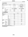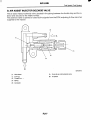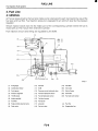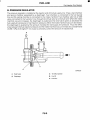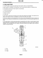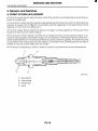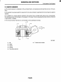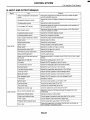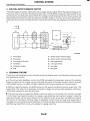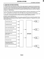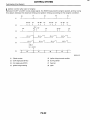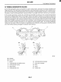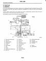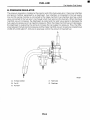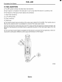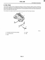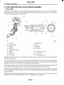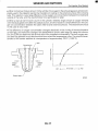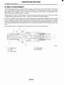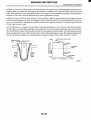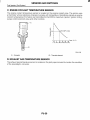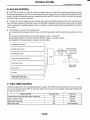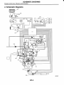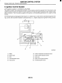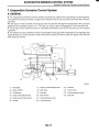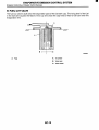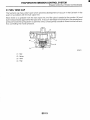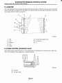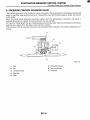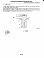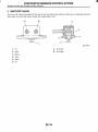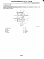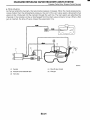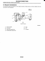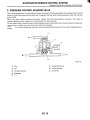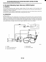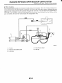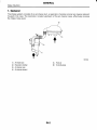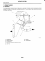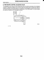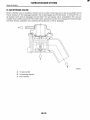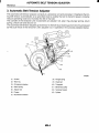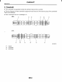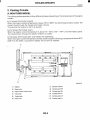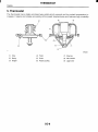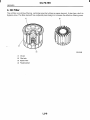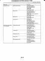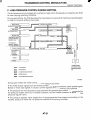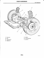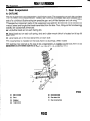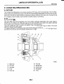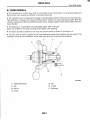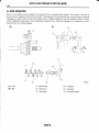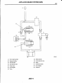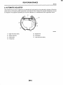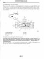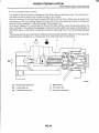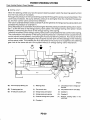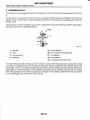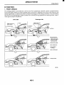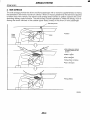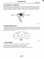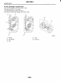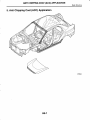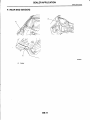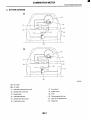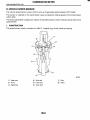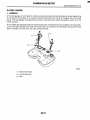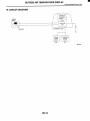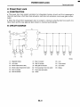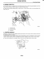
1
2002 IMPREZA SERVICE MANUAL
QUICK REFERENCE INDEX
NEW CAR INFORMATION SECTION
FOREWORD
This manual has been prepared to provide information
for the construction, operation and other technical details of SUBARU vehicles.
Read this manual thoroughly and make the most of it
to give better service to your customers and improve
your knowledge of vehicle maintenance.
All information, illustration and specifications contained in this manual are based on the latest product
information available at the time of publication approval.
FUJI HEAVY INDUSTRIES LTD.
W1830BE
FOREWORD
I)
QUICK REFERENCE INDEX
*
D
-
* e
FOREWORD
QUICK REFERENCE INDEX
FOREWORD
All right reserved. This book may not be reproduced or
copied, in whole or in part, without the written permission of FUJI HEAVY INDUSTRIES LTD., TOKYO JAPAN
@
SUBARU,
and @ are trademarks of FUJI
HEAVY INDUSTRIES LTD.
0 Copyright 2001 FUJI HEAVY INDUSTRIES LTD.
SPECIFICATIONS
SPCa
Page
1. lmpreza . . . . . ......................
. . . . . ................. . . . . . . . . ......... . . . . . . . . .. . .. . 2
IMPREZA
Specifications
1. lmpreza
A: DIMENSIONS
Model
Sedan
Wagon
OUTBACK
Overall length
mm (in)
Overall width
mm (in)
1,730 (68.1)
1,695 (66.7)
1,710 (67.3)
Overall height (at CW)
mm (in)
1,440 (56.7)
1,465 (57.7),
1,485 (58.5)*2
1,475 (58.1),
1,495 (58.9)*2
Compartment
Length
mm (in)
1,890 (74.4)
Width
mm (in)
Height
mm (in)
4,405 (173.4)
I
Wheelbase
Tread
I
1,845 (72.6)
1,380 (54.3)
1,180 (46.5)
1,200 (47.2),
1,I 50 (45.3)*3
1,200 (47.2),
1,I 50 (45.3)*3
mm (in)
2,525 (99.4)
Front
mm (in)
1,485 (58.5)
1,465 (57.7)
1,460 (57.5)
Rear
mm (in)
1,475 (58.1),
1,480 (58.3)*1
1,455 (57.3)
1,455 (57.3)
mm (in)
150 (5.9),
155 (6.1)*1
Minimum road clearance
150 (5.9),
155 (6.1)*1
160 (6.3)
B: ENGINE
Model
2.5 L
Turbo 2.0 L
Engine type
Horizontally opposed, liquid cooled, 4-cylinder, 4-stroke gasoline engine
I Valve arrangement
I
Overhead camshaft type
~~
Bore x Stroke
mm (in)
Displacement
cm3 (cu in)
Compression ratio
92 x 75
(3.62 x 2.95)
99.5 x 79.0
(3.917 x 3.1 10)
1,994 (121.67)
2,457 (149.9)
8.0
10.0
Firing order
1-3-2-4
Idle speed at ParWNeutral
position (NC OFF)
rPm
Maximum output
kW (HP)/rpm
Maximum torque
N.m (kgf-m,ft-lb)/rpm
750
650 (MT)
700 (AT)
160 (215)/6,000
123 (165)/5,600
294 (30.0, 217)/4,000
226 (23.0, 166)/4,000
SPC-2
IMPREZA
Specifications
Model
Ignitiontiming at idling speed
BTDC/rpm
Turbo 2.0 L
2.5 L
12" k 10"/750
MT: 10" f 10°/650
AT: 10" f 1O"I700
Spark plug
NGK: PFRGG
CHAMPION: RC1OYC4 (standard)
NGK: BKR5E-11
NGK: BKR6E-11
Generator
12V - 75A
12V - 90A
MT: 12V - 48AH (55D23L)
AT: 12V - 52AH (65D23L)
M I 12V - 48AH (55D23L)
AT: 12V - 52AH (75D23L)
min
MT: 99
AT: 111
MT: 99
AT: 118
amp
MT: 356
AT: 420
MT: 356
AT: 520
Battery
Type
Reserve capacity
Cold cranking
amperes
I Model
Turbo 2.0 L
Transmission type
Clutch type
I
I 1st
Gear ratio
5MTk1
4ATk2
DSPD
TCC
3.454
I
2.785
I
2nd
1.947
1.545
4th
0.972
0.694
5th
0.738
-
Reverse
3.333
2.272
Type of gear
-
Helical
Gear ratio
-
1.000
I
J
Reduction
gear (Front
drive)
1st reduction
Reduction
gear (Rear
drive)
I
I
Final
Tvpe of gear
Hypoid
Hypoid
Transfer
Type of gear
Helical
reduction
Gear ratio
Final
Tvpe of gear
1.100
Hypoid
-
I
I
Hypoid
I
5MT*l:5 forward speeds with synchromesh and 1-reverse
4AT*2:Electronically controlled fully-automatic, 4-forward speeds and 1-reverse
DSPD:Dry Single Plate Diaphragm
TCC:Torque Converter Clutch
SPC-3
I
IMPREZA
Specifications
2.5 L
Model
OTHERS
RS
Transmission type
5MTA1
Clutch type
DSPD
2nd
I
I
3rd
I
1st
4th
5th
Reverse
Dual range
Reduction
gear (Front
drive)
Reduction
gear (Rear
drive)
1st reduction
Typeofgear
Gear ratio
I
I
I
I
I
I
TCC
2.062
I
I
1.448
I
3.454
1.088
0.780
3.333
-
5MTA1
4ATA2
I
I
I
I
I
I
4ATA2
DSPD
TCC
1.619
I
I
2.062
I
I
1.000
I
1.448
I
3.027
0.694
2.272
Helical
1.000
1
I
I
I
I
I
3.454
1.088
0.780
3.333
-
-
1
I
I
I
I
I
1.545
I
I
1.ooo
I
2.785
2.272
-
Type of gear
Transfer
reduction
Final
reduction
1.000
~
Hypoid
Hypoid
Hypoid
Hypoid
Gear ratio
4.111
4.444
4.111
Type of gear
Helical
-
3.900
Helical
Gear ratio
1.ooo
-
1.000
-
Type of gear
Hypoid
Hypoid
Hypoid
Hypoid
4.111
4.444
3.900
4.111
Gear ratio
SPC-4
I
1
1
Helical
~~
Final
reduction
I
I
I
1.694
a
IMPREZA
Specifications
E: STEERING
Turns, lock to lock
Minimum turning
m (ft)
circle
3.2
3
Curb to curb
10.2 (33.5)
10.8 (35.4)
Wall to wall
11.1 (36.3)
11.7(38.3)
F: SUSPENSION
Front
Macpherson strut type, Independent, Coil spring
Rear
Dual link type, Independent, Coil spring
G: BRAKE
I
Dual circuit hydraulic with vacuum suspended power unit
Service brake system
Ventilated disc brake
Front
Disc brake
Rear
I ParkinQ brake
I
Drum brake, Disc brakekl
I
Mechanical on rear brakes
H: TIRE
TS
OTHERS
15 x 6JJ
16 x 6 '/2 JJ
P195/60R15 87H
P205/55R16 89V
Model
Rim size
Tire size
Steel belted radial, Tubeless
Type
I: CAPACITY
II Model
I
5MT
Fuel tank
Engine oil
e (US gal, Imp gal)
1 Upper level e (US qt, Imp qt)
Lower level
Transmission gear oil
Automatic transmission fluid
AT differentialgear oil
AWD rear differentialgear oil
Power steering fluid
Engine coolant
(US qt, Imp qt)
e (US qt, Imp qt)
(US qt, Imp qt)
e (US qt, Imp qt)
e (US qt, Imp qt)
e (US qt, Imp qt)
e (US qt, Imp qt)
2.5 L
Turbo 2.0 L
I
4AT
5MT
4AT
60 (15.9, 13.2)
60 (15.9, 13.2)
4.5 (4.8,4.0)
4.0 (4.2, 3.5)
3.5 (3.7,3.1)
3.0 (3.2, 2.6)
3.5 (3.7, 3.1)
-
3.5 (3.7,3.1)
-
-
9.3 (9.8,8.2)
-
9.5 (10.0,8.4)
1.2 (1.3, 1.l)
1.2(1.3, 1.1)
0.8 (0.8,0.6)
7.7 (8.1, 6.8)
SPC-5
I
0.7 (0.7, 0.6)
7.6(8.0,6.7)
I
I
7.0(7.4,6.2)
I
6.9 (7.3,6.1)
IMPREZA
Specifications
J: WEIGHT
1. U.S. SPEC. VEHICLE
Sedan
I
Model
I
Gross vehicle weight
(G.V. W.)
I Front
I Rear
I Total
Front
Rear
Total
kgf (Ib)
I
I
kgf (Ib) 1
kgf (Ib) I
kgf (Ib) I
kgf (Ib)
kgf (Ib)
I
Turbo 2.0 L
I
Curb weight (C.W.)
I
AWD
I
WRX
I
2.5 L
I
RS
5MTA1
4ATA 1
5MT
4AT
826 (1,820)
851 (1,875)
778 (1,715)
803 (1,770)
I
1
I
I
569 (1,255)
1,395 (3,075)
998 (2,200)
857 (1,890)
I
1,837 (4,050)
569 (1,255)
1,420 (3,130)
998 (2,200)
857 (1,890)
1,837 (4,050)
I
I
I
I
I
567 (1,250)
1,345 (2,965)
939 (2,070)
857 (1,890)
1,778 (3,920)
I
939 (2,070)
I
I
I
857 (1,890)
I
567 (1,250)
1,370 (3,020)
I
I
I
I
1,778 (3,920)
A1 :Excl,udesweight of side air bag.
Wagon
I
I
I
1
Model
Curb weight (C.W.)
Turbo 2.0
kgf (Ib)
Total
kgf (Ib)
I
I
5MTA1
(1,335)
606
(3,155)
Front
(2,200)
Rear
Total
L
WRX
Front
Rear
Gross vehicle weight
(G.V.W.)
AWD
I
I
2.5 L
I
TS
OUTBACK
4ATkl
5MTk2
4ATA2
5MT
4AT
851
(1,875)
773
(1,705)
603
(1,330)
1,376
(3,035)
939
(2,070)
925
(2,040)
1,833
(4,040)
796
(1,755)
783
(1,725)
601
(1,325)
1,384
(3,050)
939
(2,070)
925
(2,040)
1,833
(4,040)
805
(1,775)
603
(1,330)
1,408
(3,105)
939
(2,070)
925
(2,040)
1,033
(4,040)
605
(1,335)
1,458
(3,210)
998
(2,200)
925
(2,040)
1,901
(4,109)
A1 :Excludes weight of side air bag.
A2:Excludes weight of ABS, cruise control.
SPC-6
1
I
1
1
1
1
1
1
I
1
606
(1,335)
1,402
(3,090)
939
(2,070)
925
(2,040)
1,833
(4,040)
I
I
1
[
I
1
1
1
I
I
I
IMPREZA
Specifications
2. CANADA SPEC. VEHICLE
Model
AWD
Turbo 2.0 L
I
2.5 L
I
I
RS
WRX
Curb weight (C.W.)
4AT
5MT
4AT
I Front
kgf (Ib)
826 (1,820)
851 (1,875)
778 (1,715)
803 (1,770)
Rear
kgf (Ib)
573 (1,265)
573 (1,265)
567 (1,250)
567 (1,250)
Total
kgf (Ib)
1 Front
kgf (Ib)
I
Gross vehicle weight
(G.V.W.)
5MT
I
I
1,399 (3,085)
998 (2,200)
I
I
1,424 (3,140)
998 (2,200)
I
I
1,345 (2,965)
939 (2,070)
I
I
1,370 (3,020)
939 (2,070)
Rear
kgf (Ib)
857 (1,890)
857 (1,890)
857 (1,890)
857 (1,890)
Total
kgf (Ib)
1,837 (4,050)
1,837 (4,050)
1,778 (3,920)
1,778 (3,920)
Rear
kgf (Ib)
Total
kgf (Ib)
925
(2,040)
1,901
(4,190)
925
(2,040)
1,901
(4,190)
SPC-7
925
(2,040)
1,833
(4,040)
925
(2,040)
925
(2,040)
925
(2,040)
1,833
(4,040)
1,833
(4,040)
1,833
(4,040)
IMPREZA
SDecifications
MEMO
SPC-8
FUEL INJECTION
(FUEL SYSTEM)
1.
2.
3.
4.
5.
6.
FU
WHC)
General . . . . . . . . . . . . . . . . . . . . . . . . . . . . . . . . . . . . . . . . . . . . . . . . . . . . . . . . . . . . . . . . . . . . . . . . . . . . . . . .
2
. .
Air Line . . . . . . . . . . . . . . . . . . . . . . . . . . . . . . . . . . . . . . . . . . . . . . . . . . . . . . . . . . . . . . . . . . . . . . . . . . . . . . . . Page
3
Fuel Line . . . . . . . . . . . . . . . . . . . . . . . . . . . . . . . . . .
..
Sensors and Switches . . . . . . . . . . . . . . . . . . . . . . . . . . . . . . . . . . . . . . . . . . . . . . . . . . . . . . . . . . . 16
Control System . . . . . . . . . . . . . . . . . . . . . . . . . . . . . . . .
. . . . . . . . . . . . . . . . . . . 26
On-board Diagnosis System . . . . . . . . . . . . . . . . . . . . . . . . . . . . . . . . . . . . . . . . . . . . . . . . . . . . . . . 34
I
GENERAL
Fuel Injection (Fuel System)
1. General
The Multipoint Fuel Injection (MFI) system supplies optimum air-fuel mixture under every engine
operating condition through the use of the latest electronic control technology.
0
This system pressurizes the fuel to a constant pressure and injects it into each intake air port in
the cylinder head. The injection quantity of fuel is controlled by an intermittent injection system
where an electro-magnetic injection valve or injector opens for a short period that is precisely controlled depending on the quantity of air appropriate for each condition of operation. In actual control, an optimum fuel injection quantity is achieved by varying the duration of an electric pulse applied to the injector. This way of control enables simple, yet highly precise metering of the fuel.
0 The engine control module (ECM) that controls the fuel injection system corrects the fuel injection amount depending on the vehicle speed, throttle opening, coolant temperature and other vehicle-operation-related information. The ECM receives the information in the form of electric signals from the corresponding sensors and switches.
The MFI system also has the following features:
0
Reduced exhaust emissions
0
Reduced fuel consumption
0
Increased engine output
0
Quick response to accelerator and brake pedal operation
Superior startability and warm-up performance in cold weather due to corrective controls made
according to coolant and intake air temperatures
FU-2
AIR LINE
Fuel Injection (Fuel System)
2. Air Line
A: GENERAL
The air filtered by the air cleaner enters the throttle body where it is regulated in the volume by the
throttle valve and then enters the intake manifold. It is then distributed to each cylinder where the
air is mixed with fuel injected by the injector. During idling operation, air flows into the cylinder
through the idle air control solenoid valve, bypassing the throttle valve. This enables controlling
the engine idling speed properly.
B: INTAKE MANIFOLD PRESSURE AND AIR TEMPERATURE SENSORS
The intake manifold pressure sensor and the intake air temperature sensor are integrated into a
single unit. The unit is mounted on the intake manifold and measures the absolute air pressure in
the intake manifold as well as the temperature of the intake air.
The measured pressure and temperature are converted into electrical signals and sent to the
ECM. The ECM uses these signals to control injection and ignition timing as well as the fuel injection amount.
H2H2825B
(1) Pressure sensor
(2) Intake air temperature sensor
FU-3
I
AIR LINE
Fuel Injection (Fuel System)
C: ATMOSPHERIC PRESSURE SENSOR
The atmospheric pressure sensor converts pressure values into electric signals, and sends the
signals to the ECM.
NF0007
(1) Sensor unit
(6) Terminal
(2) O-ring
(7) Inner lead
(3) Case
(8) Resin
(4) Pipe
(9) Metal lid
(5) Through capacity
D: THROTTLE BODY
In response to operation of the accelerator pedal, the throttle valve in the throttle body opens/
closes to regulate the volume of the air drawn into the combustion chamber.
0 During idling, the throttle valve is almost fully closed and the volume of air passing through the
throttle body is less than that passing through the idle air control solenoid valve.
0 More than half of the air necessary for idling is supplied to the intake manifold via the idle air
control solenoid valve which controls properly the engine idling speed, so the idling speed needs
not be adjusted.
FU-4
a
AIR LINE
Fuel Injection (Fuel System)
E: THROTTLE POSITION SENSOR
0
The throttle position sensor is mounted in the throttle body and linked to the throttle valve.
The throttle position sensor sends the ECM voltage signal corresponding to the opening of the
throttle valve. When the sensor’s output voltage exceeds a predetermined level, the ECM interprets it as complete closure of the throttle valve. When the output voltage is at another predetermined level, the ECM recognizes that the throttle valve is at a wide open position. Since the output
characteristics of the sensor change over years, the ECM is provided with a learning function to
be able to interpret signals into throttle valve angles always correctly.
0
I
B2H2004B
(1) Lever
(2) Terminal
FU-5
AIR LINE
Fuel Injection (Fuel System)
F: IDLE AIR CONTROL SOLENOID VALVE
0 The idle air control solenoid valve is located in the throttle body and regulates the amount of intake air that flows bypassing the throttle valve into the intake manifold during engine idling. It is
activated by a signal from the ECM in order to maintain the engine idling speed at a target speed.
0 The idle air control solenoid valve is a stepping motor type solenoid-actuated valve which consists of coils, a shaft, a permanent magnet, a spring and a housing. The housing is an integral part
of the throttle body.
The stepping motor consists of two paired coils, the coils of each pair being arranged face to
face with a shaft in between.
0
The shaft has a screw at the end around which the permanent magnets are arranged.
As current flows in the form of pulses through the paired coils sequentially while alternating the
polarity, the N and S poles of the permanent magnets around the shaft are repelled by the same
poles of the magnetism generated by the coils. This causes a nut externally fixed to the magnets
and internally engaging with the screw of the shaft to turn.
The shaft then goes upward or downward.
0
This upward and downward motions of the shaft open or close the valve port, adjusting the
amount of bypass air.
B2H2005B
(1) Connector
(2) Permanent magnet
(3) Shaft
(4) Coil
(5) Spring
FU-6
m
I
AIR LINE
Fuel
Injection (Fuel System)
G: AIR ASSIST INJECTOR SOLENOID VALVE
The air assist injector solenoid valve is located in the piping between the throttle body and the injector and secured to the intake manifold.
This solenoid valve is opened or closed by the signals from the ECM, adjusting the flow rate of air
supplied to the injector.
82H34478
(1) Valve sheet
A: From idle air control solenoid valve
(2) Solenoid
B: To injector
(3) Plunger and valve
(4) Spring
(5) Connector
FU-7
FUEL LINE
Fuel Injection (Fuel System)
3. Fuel Line
A: GENERAL
The fuel pressurized by the fuel tank inside pump is delivered to each fuel injector by way of the
fuel pipe and fuel filter. Fuel injection pressure is regulated to an optimum level by the pressure
regulator.
0
Each injector injects fuel into the intake port of the corresponding cylinder where the fuel is
mixed with air. The mixture then enters the cylinder.
0
Fuel injection amount and timing are regulated by the ECM.
NF0477
(1) Fuel gauge
Canister
(19) Fuel tank
(2) Combination meter
ECM
(20) Vent valve
(3) Fuel injector
Pressure control solenoid valve
(21) Shut-off valve
(4) Pressure regulator
Fuel tank pressure sensor
(22) Drain filter
(5) Throttle body
Fuel temperature sensor
(23) Fuel sub level sensor
(6) Intake manifold
Fuel level sensor
(7) Fuel filter
Fuel pump
(8) Purge control solenoid valve
Jet pump
(a) Fuel line
(9) Drain valve
Fuel cut valve
(b) Evaporation line
FU-8
FUEL LINE
Fuel lniection (Fuel System\
B: PRESSURE REGULATOR
The pressure regulator is installed at the injector end of the fuel supply line. It has a fuel chamber
and spring chamber separated by a diaphragm. Fuel chamber is connected to the fuel supply
line and the spring chamber is connected to the intake manifold. Fuel chamber also has a relief
valve connected to the fuel return line through which fuel returns to the fuel tank. When the intake
manifold vacuum increases, the diaphragm is pulled and the relief valve opens to decrease the
fuel supply line pressure (or fuel injection pressure). When the intake manifold vacuum decreases,
the diaphragm is pushed by the spring to increase the fuel supply line pressure. Thus, the difference between the fuel injection pressure and the intake manifold vacuum is kept at a constant level
of 299.1 kPa (3.05 kgf/cm2, 43.4 psi) to precisely control the amount of injected fuel.
A
S2H0623C
A: To intake manifold
(1) Relief valve
B: Fuel IN
(2) Diaphragm
C: FuelOUT
FU-9
I
FUEL LINE
Fuel Injection (Fuel System)
C: FUEL INJECTORS
0
The MFI system employs top feed type fuel injectors with an air assist feature.
0
Each injector is installed in the fuel pipe in such a way that the injector is cooled by fuel.
0
The features of this type of fuel injector are as follows:
1) High heat resistance
2) Low driving noise
3) Easy to service
4) Small size
The injector injects fuel according to the valve open signal from the ECM. The needle valve is
lifted by the solenoid which is energized on arrival of the valve open signal.
0
Since the injector’s nozzle hole area, the lift of valve and the fuel pressure are kept constant, the
amount of fuel injected is controlled only by varying the duration of the valve open signal from the
ECM.
0
Fuel atomization is enhanced using assist air supplied from the idle air control solenoid valve
passing through the passage formed in the intake manifold at the area in which each injector is
installed. This contributes not only to higher combustion efficiency and higher output but also to
cleaner exhaust emissions.
0
S2H1943A
(1) Filter
(4) Seal
(2) O-ring
(5) O-ring
(3) Plunger
(6) Connector
FU-10
FUEL LINE
Fuel Injection (Fuel System)
D: FUEL TANK
The fuel tank utilizes a two-compartment design to ensure sufficient capacity without interfering
with the rear differential. It is provided with a suction jet pump (included in the fuel pump and fuel
level sensor assembly) which transfers fuel from one compartment to the other. Each compartment
has an individual fuel level sensor.
The fuel tank is located under the rear seat and secured with hold-down bands.
NF0473
(1 ) Fuel pump and fuel level sensor assembly
(4) Cushion
(2) Fuel sub level sensor
(5) Steel
(3) Band
FU-11
FUEL LINE
Fuel Injection (Fuel System)
E: FUEL PUMP AND FUEL LEVEL SENSOR ASSEMBLY
1. FUELPUMP
The fuel pump consists of a motor, impeller, pump casing, pump cover, check valve and filter. It
is located in the fuel tank and combined with the fuel level sensor into a single unit. The operation
of this impeller type pump is very quiet.
NF0474
(9) Motor armature
(1) Fuel pump
(2) Fuel level sensor
(IO) Suction
(3) Jet pump
(11) Discharge
(4) Mesh filter
(12) Vane groove
(5) Fuel temperature sensor
(6) Impeller
A: From engine (return line)
(7) Check valve
B: From sub tank
(8) Pump casing
C: To engine (delivery line)
When the ignition switch is turned ON, fuel pump relay is activated. Then the motor operates
to rotate the impeller.
0
As the impeller rotates, fuel in a vane groove of the impeller flows along the fuel passage into
the next vane groove by centrifugal force. When fuel flows from one groove to the next, a pressure
difference occurs due to friction. This creates a pumping effect.
0
0 The fuel pushed up by rotation of the impeller then passes through the clearance between the
armature and the magnet of the motor and is discharged through the check valve.
0 When the fuel discharge pressure reaches the specified level, the relief valve opens and excess
fuel is released into the fuel tank. In this manner, the relief valve prevents an abnormal increase
in fuel pressure.
0 When the engine and the fuel pump stop, spring force acts on the check valve to close the discharge port, so that the fuel pressure in the fuel delivery line is retained.
FU-12
FUEL LINE
Fuel Injection (Fuel System)
2. FUEL LEVEL SENSOR
The fuel level sensor forms part of the fuel pump and located in the fuel tank. The sensor outputs
an electric resistance signal that varies with movement of its float to indicate the level of the fuel
remaining in the tank.
NF0327
(1) Fuel level sensor
(2) Float
FU-13
FUEL LINE
Fuel Injection (Fuel System)
3. JETPUMP
The jet pump utilizes the velocity of fuel returning from the engine to produce negative pressure
in it.
0
0 Using the pumping effect produced by the negative pressure, the jet pump transfers fuel from
the sub-compartment to the main compartment of the fuel tank.
0 When the return line nozzle is clogged, the fuel sent back through the return line flows back into
the fuel tank via the relief valve.
A
+
t
A: Return line
(1) Relief valve
(2) Nozzle
FU-14
A
m
FUEL LINE
Fuel lniection (Fuel System)
F: SUB-COMPARTMENT FUEL LEVEL SENSOR
This sensor detects the level of the fuel in the sub-compartment (the compartment in which the
fuel pump is not located) and acts as part of the fuel transfer line when the jet pump is in operation
to maintain the fuel in both compartments at the same level.
NF0396
A: Tojet pump
(1) Fuel level sensor
(2) Float
G: FUEL FILTER
The fuel filter located in the engine compartment is a pressure-withstanding, cartridge type. It has
a filter element in a metal case. The fuel entering the filter flows from the perimeter of the element
to the center of the filter and goes out from there.
NF0018
FU-15
SENSORS AND SWITCHES
Fuel lniection (Fuel Svstem)
4. Sensors and Switches
A: FRONT OXYGEN (NF)SENSOR
The front oxygen sensor uses zirconium oxide (Zr02) which is a solid electrolyte, at portions exposed to exhaust gas.
0
The zirconium oxide has the property of generating electromotive force when its both sides are
exposed to oxygen ions of different concentration and the magnitude of this electromotive force
depends on how much the difference is.
0
The front oxygen sensor detects the amount of oxygen in exhaust gases by making use of this
property of the zirconium oxide material.
0
The zirconium oxide material is formed into a closed end tube and its external surface is exposed to exhaust gases with smaller oxygen ion concentration, whereas its internal surface is exposed to atmospheric air. The external surface has a porous platinum coating. The sensor housing
is grounded to the exhaust pipe and the inside is connected to the ECM through the harness to
be able to use the current output from the sensor.
0
0
The sensor incorporates a ceramic heater to improve its performance at low temperatures.
Y
(3)
1-
I
(4)
S2H1791B
(1) Sensor element
(2) Sensor housing
(3) Protection tube
(4) Gasket
FU-16
SENSORS AND SWITCHES
Fuel Injection (Fuel System)
When rich air-fuel mixture is burnt in the cylinder, the oxygen in the exhaust gases is almost completely used in the catalytic reaction by the platinum coating on the external surface of the zirconia
tube. This results in a very large difference in the oxygen ion concentration between the inside and
outside of the tube, and the electromotive force generated is large.
0
When a lean air-fuel mixture is burnt in the cylinder, relatively large amount of oxygen remains
in the exhaust gases even after the catalytic action, and this results in a small difference in the oxygen ion concentration between the tube's internal and external surfaces. The electromotive force
in this case is very small.
0
0 The difference in oxygen concentration changes drastically in the vicinity of the stoichiometric
air-fuel ratio, and hence the change in the electromotive force is also large. By using this information, the ECM can determine the air-fuel ratio of the supplied mixture easily. The front oxygen sensor does not generate much electromotive force when the temperature is low. The output characteristics of the sensor stabilize at a temperature of approximately 700°C (1,292"F).
Atmospheric air
/- Zro2
Lean
-
Air-fuel ratio
-
Rich
Ceramic heater -.J
NF0331
FU-17
SENSORS AND SWITCHES
Fuel lniection (Fuel System)
B: REAR OXYGEN SENSOR
The rear oxygen sensor is used to sense oxygen concentration in the exhaust gas. If the air-fuel
ratio is leaner than the stoichiometric ratio in the mixture (i.e., excessive amount of air), the exhaust
gas contains more oxygen. To the contrary, if the fuel ratio is richer than the stoichiometric ratio,
the exhaust gas contains almost no oxygen.
0
Detecting the oxygen concentration in exhaust gas using the oxygen sensor makes it possible
to determine whether the air-fuel ratio is leaner or richer than the stoichiometry.
0
The rear oxygen sensor has azirconia tube (ceramic) which generates voltage if there is a difference in oxygen ion concentration between the inside and outside of the tube. Platinum is coated
on the inside and outside of the zirconia tube as a catalysis and electrode material. The sensor
housing is grounded to the exhaust pipe and the inside is connected to the ECM through the harness.
0
0
A ceramic heater is employed to improve performance at low temperatures.
/
(4)
\\
\
(5)
B2H381OC
(1) Protectiontube
(4) Gasket
(2) Ceramic heater
(5) Sensor housing
(3) Zirconia tube
(6) Harness
FU-18
SENSORS AND SWITCHES
Fuel lniection (Fuel System)
When rich air-fuel mixture is burnt in the cylinder, the oxygen in the exhaust gases is almost completely used in the catalytic reaction by the platinum coating on the external surface of the zirconia
tube. This results in a very large difference in the oxygen ion concentration between the inside and
outside of the tube, and the electromotive force generated is large.
0
When a lean air-fuel mixture is burnt in the cylinder, relatively large amount of oxygen remains
in the exhaust gases even after the catalytic action, and this results in a small difference in the oxygen ion concentration between the tube's internal and external surfaces. The electromotive force
in this case is very small.
0
0s
as rich
s o
C
L
.p sz
-
-
E%
-t
Comparison
voltage
~
-
4
gz%
25
s
To be judged
- x o
w o >
Small
C: ENGINE COOLANT TEMPERATURE SENSOR
The engine coolant temperature sensor is located on the engine coolant pipe. The sensor uses
a thermistor whose resistance changes inversely with temperature. Resistance signals as engine
coolant temperature information are transmitted to the ECM to make fuel injection, ignition timing,
purge control solenoid valve and other controls.
A
1
-20
(-4)
Temp. "C ( O F )
0
20 40 60 80
(32) (68) (104)(140)(176)
S2H1113B
(2) Thermistor element
(1) Connector
FU-19
SENSORS AND SWITCHES
Fuel Injection (Fuel System)
D: CRANKSHAFT POSITION SENSOR
The crankshaft position sensor is installed on the oil pump which is located in the front center
portion of the cylinder block. The sensor generates a pulse when one of the teeth on the perimeter
of the crankshaft sprocket (rotating together with the crankshaft) passes in front of it. The ECM determines the crankshaft angular position by counting the number of pulses.
The crankshaft position sensor is a molded type which consists of a magnet, core, coil, terminals
and other components as illustrated below.
NF0024
(1) Terminal
(4) Coil
(2) Yoke core
(5) Core
(3) Magnet
(6) Cover
FU-20
SENSORS AND SWITCHES
Fuel Injection (Fuel System)
As the crankshaft rotates, each tooth aligns with the crankshaft position sensor. At that time, the
magnetic flux in the sensor’s coil changes since the air gap between the sensor pickup and the
sprocket changes. This change in magnetic flux induces a voltage pulse in the sensor and the
pulse is transmitted to the ECM.
0
NF0398
(1) Crankshaft position sensor
(2) Crankshaft sprocket
(3) Crankshaft half rotation
FU-21
SENSORS AND SWITCHES
Fuel Injection (Fuel System)
E: CAMSHAFT POSITION SENSOR
The camshaft position sensor is located on the left-hand camshaft support. It detects the combustion cylinder at any given moment.
0
0 The sensor generates a pulse when one of the bosses on the back of the left-hand camshaft
drive sprocket passes in front of the sensor. The ECM determines the camshaft angular position
by counting the number of pulses.
Internal construction and the basic operating principle of the camshaft position sensor are similar
to those of the crankshaft position sensor. A total of seven bosses are arranged at equally spaced
four locations (one each at two locations, two at one location, and three at one location) of the
sprocket as shown below.
S2H1813A
(1) Boss
(4) Camshaft position sensor
(2) Camshaft sprocket
(5) Boss
(3) Airgap
(6) Camshaft one rotation (Crankshafttwo rotations)
FU-22
I
SENSORS AND SWITCHES
Fuel Injection (Fuel System)
F: KNOCK SENSOR
The knock sensor is installed on the cylinder block, and senses knocking that occurs in the engine.
0
The sensor is a piezo-electric type which converts vibration resulting from knocking into electric
signals.
0
In addition to a piezo-electric element, the sensor has a weight and case as its components.
If knocking occurs in the engine, the weight in the case moves causing the piezo-electric element
to generate a voltage.
0
0
The knock sensor harness is connected to the bulkhead harness.
(2)
B2H1998B
A: To knock sensor harness
(1) Nut
(2) Weight
(3) Resistor
(4) Housing
(5) Piezo-electric element
FU-23
SENSORS AND SWITCHES
Fuel lniection (Fuel System)
G: VEHICLE SPEED SENSOR
1. MT VEHICLES
0 The vehicle speed sensor is mounted on the transmission.
0 The vehicle speed sensor generates a 4-pulse signal for every rotation of the front differential
and send it to the ECM and the combination meter.
B2H2458C
(1) Combination meter
(2) ECM
(3) Vehicle speed sensor
(4) Transmission
FU-24
SENSORS AND SWITCHES
Fuel Injection (Fuel System)
2. AT VEHICLES
0 The vehicle speed sensor is mounted on the transmission.
The vehicle speed sensor generates a 16-pulse signal for every rotation of the front differential
and send it to the transmission control module (TCM). The signal sent to the TCM is converted
there into a 4-pulse signal, and then sent to the ECM and the combination meter.
0
62H24596
(1) Combination meter
(2) ECM
(3) TCM
(4) Vehicle speed sensor
(5) Transmission
FU-25
CONTROL SYSTEM
Fuel lniection (Fuel System)
5. Control System
A: GENERAL
The ECM receives signals from various sensors, switches, and other control modules. Using these
signals, it determines the engine operating conditions and if necessary, emits signals to one or
more systems to control them for optimum operation.
Major control items of the ECM are as follow:
0
Fuel injection control
0
Ignition system control
0
Idle air control
0
Fuel pump control
0
Canister purge controt*1
0
Radiator fan control**
0
On-board diagnosis function
*I : Canister purge control is described under “EC (SOHC) - Emission Control (Aux. Emission Control Devices) Evaporative Emission Control System”.
*2: Radiator fan control is described under “CO - Cooling”.
FU-26
CONTROL SYSTEM
Fuel Injection (Fuel System)
B: INPUT AND OUTPUT SIGNALS
~
~
Function
Unit
Signal
~~
~
Intake air temperature and pressure
sensor
Detects the temperature of intake and amount of intake air (Measures the absolute pressure).
Atmospheric pressure sensor
Detects the amount of intake air (Measure the atmospheric pressure).
Throttle position sensor
Detects the throttle valve position.
Front oxygen (NF) sensor
Detects the density of oxygen in exhaust gases at the upstream of
the front catalytic converter.
Rear oxygen sensor
Detects the density of oxygen in exhaust gases at the downstream
of the front catalytic converter.
Crankshaft position sensor
Detects the crankshaft angular position.
Camshaft position sensor
Detects the combustion cylinder.
Engine coolant temperature sensor
Detects the engine coolant temperature.
Knock sensor
Detects engine knocking.
Vehicle speed sensor
Detects the vehicle speed.
Ignition switch
Detects operation of the ignition switch.
Starter switch
Detects the condition of engine cranking.
Neutral position switch (MT)
Detects that the gear is in neutral.
ParWNeutral position switch (AT)
Detects shift positions.
Torque control signal (AT)
Controls engine torque.
Heater circuit of front and rear oxygen sensor
Detects abnormality in the heater circuit of the front and rear oxygen
sensors.
Diagnostics of TCM (AT)
Detects the self-diagnostics of the TCM.
N C switch
Detects ON-OFF operation of the A/C switch.
Fuel temperature sensor
Detects the temperature of the fuel in the fuel tank.
Fuel level sensor
Detects the level of the fuel in the fuel tank.
nput signals
Fuel tank pressure sensor
Detects the evaporation gas pressure in the fuel tank.
Small light switch
Detects ON-OFF operation of the small light switch.
Blower fan switch
Detects ON-OFF operation of the blower fan switch.
Rear defogger switch
Detects ON-OFF operation of the rear defogger switch.
Fuel Injector
Activates an injector.
Ignition signal
Turns the primary ignition current ON or OFF.
Fuel pump relay
Turns the fuel pump relay ON or OFF.
~~
~~
~~
3utput signals
N C control relay
Turns the N C control relay ON or OFF.
Radiator fan control relay
Turns the radiator fan control relay ON or OFF.
Idle air control solenoid valve
Adjusts the amount of air flowing through the bypass line in the
throttle body.
Malfunction indicator lamp
Indicates existence of abnormality.
Purge control solenoid valve
Controls purge of evaporative gas absorbed by the canister.
Power supply
Control ON/OFF of the main power supply relay.
Pressure control solenoid valve
Controls evaporation gas pressure in the fuel tank.
Drain valve
Closes the evaporation line between the fuel tank and canister to
detect leakage of evaporation gases.
FU-27
CONTROL SYSTEM
Fuel Injection (Fuel System)
C: FUEL INJECTION CONTROL
0 The ECM receives signals from various sensors and based on them, it determines the amount
of fuel injected and the fuel injection timing. It performs the sequential fuel injection control over
the entire engine operating range except during start-up of the engine.
The amount of fuel injected depends upon the length of time the injector stays open. The fuel
injection duration is determined according to varying operating condition of the engine. For the
purpose of achieving highly responsive and accurate fuel injection duration control, the ECM performs a new feedback control that incorporates a learning feature as detailed later.
0
The sequential fuel injection control is performed such that fuel is injected accurately at the time
when the maximum air intake efficiency can be achieved for each cylinder (i.e., fuel injection is
completed just before the intake valve begins to open).
0
1. FUEL INJECTION DURATION
Fuel injection duration is basically determined as indicated below:
During engine start-up:
The duration defined below is used.
0 Duration of fuel injection during engine start-up ..... Determined according to the engine coolant temperature detected by the engine coolant temperature sensor.
0
0 During normal operation:
The duration is determined as follows:
Basic duration of fuel injection x Correction factors
+ Voltage correction time
Basic duration of fuel injection ..... The basic length of time fuel is injected. This is determined
by two factors -the amount of intake air detected by the manifold pressure sensor and the engine speed monitored by the crankshaft position sensor.
0 Correction factors ..... See the next section.
0 Voltage correction time ..... This is added to compensate for the time lag before operation of
injector that results from variation in the battery voltage.
0
FU-28
CONTROL SYSTEM
Fuel lniection (Fuel System)
2. CORRECTION FACTORS
The following factors are used to correct the basic duration of fuel injection in order to make the
air-fuel ratio meet the requirements of varying engine operating conditions:
0 Air-fuel ratio feedback factor:
This factor is used to correct the basic duration of fuel injection in relation to the actual engine
speed. (See the next section for more detail.)
0 Start increment factor:
This factor is used to increase the fuel injection duration only while the engine is being cranked
to improve its startability.
Coolant-temperature-dependent increment factor:
This factor is used to increase the fuel injection duration depending on engine coolant temperature
signals to facilitate cold starting. The lower the coolant temperature, the greater the increment.
0
0
After-start increment factor:
0 This factor is used to increase the fuel injection duration for a certain period immediately after
start of the engine to stabilize engine operation.
0 The increment depends on the coolant temperature at the start of the engine.
0 Wide-open-throttle increment factor:
This factor is used to increase the fuel injection duration depending on the relationship between
the throttle position sensor signal and manifold pressure sensor signal.
Acceleration increment factor:
This factor is used to increase the fuel injection duration to compensate for a time lag between air
flow measurement and fuel injection control for better engine response to driver’s pedal operation
during acceleration.
0
FU-29
CONTROL SYSTEM
Fuel Injection (Fuel System)
3. AIR-FUEL RATIO FEEDBACK FACTOR
The ECM creates this factor utilizing the front oxygen sensor signal. When the signal voltage is low,
the air-fuel ratio is richer than the stoichiometric ratio. The ECM then makes the fuel injection duration shorter by modifying the factor. When the voltage is high showing that the mixture is lean, the
ECM modifies the factor to make the injection duration longer. In this way, the air-fuel ratio is maintained at a level close to the stoichiometric ratio at which the three-way catalyst acts most effectively.
B2H0989B
(1) Front catalyst
A: Injection duration increment signal
(2) Exhaust gas
B: Injection duration decrement signal
(3) Front oxygen (NF) sensor
C: High oxygen density
(4) Fuel injector
D: Low oxygen density
(5) Combustion chamber
E: Lean signal
F: Rich signal
(6) ECM
4. LEARNING FEATURE
The air-fuel ratio feedback control includes a learning feature which contributes to more accurate
and responsive control.
In the air-fuel ratio feedback control, the ECM calculates the necessary amount of correction
based on data from the oxygen sensor and adds the result to the basic duration (which is stored
in the ECM’s memory for each condition defined by the engine speed and various loads.)
0
0 Without a learning feature, the ECM carries out the above-mentioned process every time. This
means that if the amount of necessary correction is large, the air-fuel ratio feedback control becomes less responsive and less accurate.
The learning feature enables the ECM to store the amount of correction into memory and add
it to the basic fuel injection duration to create a new reference fuel injection duration. Using the
reference duration as the basic duration for the injection a few times later, the ECM can reduce
the amount of correction and thus make its feedback control more accurate and responsive to
changes in the air-fuel ratio due to difference in driving condition and sensor/actuator characteristics that may result from unit-to-unit variation or aging over time.
FU-30
m
CONTROL SYSTEM
Fuel lniection (Fuel Svstem)
D: IGNITION SYSTEM CONTROL
The ECM determines operating condition of the engine based on signals from the pressure sensor, engine coolant temperature sensor, intake air temperature sensor, crankshaft position sensor
and other sources. It then selects the ignition timing most appropriate for the condition thus determined from those stored in its memory and outputs at that timing a primary current OFF signal to
the ignitor to initiate ignition.
0
This control uses a quick-to-response learning feature by which the data stored in the ECM
memory is processed in comparison with information from various sensors and switches.
0
0 Thus, the ECM can always perform optimum ignition timing taking into account the output, fuel
consumption, exhaust gas, and other factors for every engine operating condition.
0 Ignition control during start-up
Engine speed fluctuates during start of the engine, so the ECM cannot control the ignition timing.
During that period, the ignition timing is fixed at 10" BTDC by using the IO" signal from the crank-
Crankshaft position sensor
b
Camshaft position sensor
*
Engine coolant temperature sensor
*
Atmospheric pressure sensor
e
1
I
I
Intake air temperature and
pressuresensor
I
ECM
I
Knock sensor
Throttle position sensor
I
I *
Neutral position switch (MT)
ParWNeutralposition switch (AT)
NC switch
1
b
I
I
I
Ignitioncoil and
ignitor assembly
1
I
*I
-
NF0031
FU-31
CONTROL SYSTEM
Fuel Injection (Fuel System)
Ignition control after start of engine
Between the 97" and 65" crank angle signal, the ECM measures the engine speed, and by using
this data it decides the dwell set timing and ignition timing according to the engine condition.
(1)
#4
#1
#3
#2
#4
I
I
I
I
I
97" 65"
I 1
(2)
10"
97" 65"
I
I I
97" 65"
10"
I
I I
10"
1
97" 65"
I I
10"
I
27.5"
501 [
20"
(6)
I
#4
i
20"
#1
I
20"50"
#3
I
20"
#2
I
B2H041OD
(1) Cylinder number
(5) Ignition timing at normal condition
(2) Crank angle pulse (BTDC)
(6) Burning cylinder
(3) Cam angle pulse (ATDC)
(7) Dwellset
(4) Ignition timing at starting
(8) Ignite
FU-32
CONTROL SYSTEM
Fuel lniection (Fuel Svstem)
E: IDLE AIR CONTROL
The ECM activates the idle air control solenoid valve to control the bypass air flowing through
the bypass passage in the throttle body depending on signalsfrom the crankshaft position sensor,
engine coolant temperature sensor, pressure sensor and A/C switch so that the proper idle speed
for each engine load is achieved.
0
0 The idle air control solenoid valve uses a duty-ratio-controlled solenoid which can continuously
vary the opening area of the rotary valve. As the ECM increases the duty ratio, opening of the rotary
valve increases so that the bypass air flow increases, and the engine idling speed becomes higher
as a result.
0
The bypass air control is necessary for:
0 Increasing idling speed when the air conditioning system and/or electrical loads are turned
on.
0 Increasing idling speed during early stage of warm up period.
0 Obtaining dashpot function when the throttle valve is quickly closed.
0 Prevention of engine speed variation during idling.
Intake air temperature and pressure sensor
Crankshaft position sensor
Camshaft position sensor
Throttle position sensor
Engine coolant temperature sensor
ECM
Ignition switch
Idle air control solenoid valve
A/C switch
Neutral position switch (MT)
ParWNeutral position switch (AT)
NF0033
F: FUEL PUMP CONTROL
Using the signal from the crankshaft position sensor, the ECM controls operation of the fuel pump
by turning its relay ON or OFF. To improve safety, the fuel pump is stopped if the engine stalls with
the ignition switch ON.
~~~~
~
Ignition switch ON
I
Fuel pump relay
I
Fuel pump
A certain period of time after ignition switch is turned ON
ON
Operates
While cranking the engine
ON
Operates
While engine is operating
ON
Operates
When enaine stoos
OFF
Does not operate
FU-33
I
ON-BOARD DIAGNOSIS SYSTEM
Fuel Injection (Fuel System)
6. On-board Diagnosis System
A: GENERAL
The on-board diagnosis system detects and indicates a fault by generating a code corresponding to each fault location. The malfunction indicator lamp (CHECK ENGINE light) on the combination meter indicates occurrence of a fault or abnormality.
0
When the malfunction indicator lamp comes on as a result of detection of a fault by the ECM,
the corresponding diagnostic trouble code (DTC) and freeze frame engine condition are stored
in the ECM.
0
0 On the OBD-I1 conformable car, it is necessary to connect the Subaru Select Monitor (SSM) or
General Scan Tool (GST) to the data link connector in order to check the DTC.
0 The SSM and GST can read and erase DTCs. They can also read freeze frame data in addition
to other pieces of engine data.
0 If there is a failure involving sensors which may affect drive control of the vehicle, the fail-safe
function ensures minimum level of driveability.
B: FAIL-SAFE FUNCTION
For a sensor or switch which has been judged faulty in the on-board diagnosis, the ECM, if appropriate, generates an associated pseudo signal to keep the vehicle operational. (The control
becomes degraded .)
FU-34
FUEL INJECTION
(FUEL SYSTEM)
1.
2.
3.
4.
5.
6.
Page
General . . . . . . . . . . . . . . . . . . . . . . . . . . . . . . . . . . . . . . . . . . . . . . . . . . . . . . . . . . . . . . . . . . . . . . . . . . . . . . . .
2
. .
Air Line . . . . . . . . . . . . . . . . . . . . . . . . . . . . . . . . . . . . . . . . . . . . . . . . . . . . . . . . . . . . . . . . . . . . . . . . . . . . . . . .
3
Fuel Line . . . . . . . . . . . . . .
...................
.....................
..........
Sensors and Switches . . . . . . . . . . . .
...................
....................
16
Control System . . . . .
......................
. . . . . . . . . . 27
On-board Diagnosis System . .
.......................
36
8a
GENERAL
Fuel lniection (Fuel System)
1. General
The Multipoint Fuel Injection (MFI) system supplies optimum air-fuel mixture under every engine
operating condition through the use of the latest electronic control technology.
0
This system pressurizes the fuel to a constant pressure and injects it into each intake air port in
the cylinder head. The injection quantity of fuel is controlled by an intermittent injection system
where an electro-magnetic injection valve or injector opens for a short period that is precisely controlled depending on the quantity of air appropriate for each condition of operation. In actual control, an optimum fuel injection quantity is achieved by varying the duration of an electric pulse applied to the injector. This way of control enables simple, yet highly precise metering of the fuel.
The engine control module (ECM) that controls the fuel injection system corrects the fuel injection amount depending on the vehicle speed, throttle opening, coolant temperature and other vehicle-operation-related information. The ECM receives the information in the form of electric signals from the corresponding sensors and switches.
0
The MFI system also has the following features:
0
Reduced exhaust emissions
0
Reduced fuel consumption
0
Increased engine output
0
Quick response to accelerator and brake pedal operation
Superior startability and warm-up performance in cold weather due to corrective controls made
according to coolant and intake air temperatures
0
FU-2
AIR LINE
Fuel Injection (Fuel System)
2. Air Line
A: GENERAL
The air filtered by the air cleaner enters the throttle body where it is regulated in the volume by the
throttle valve and then enters the intake manifold. It is then distributed to each cylinder where the
air is mixed with fuel injected by the injector. During idling operation, air flows into the cylinder
through the idle air control solenoid valve, bypassing the throttle valve. This enables controlling
the engine idling speed properly.
B: PRESSURE SENSOR
The pressure sensor is attached to the top of the throttle body, and continuously sends to the engine control module (ECM) voltage signals that are proportional to intake manifold absolute pressures. The ECM controls the fuel injection and ignition timing based on the intake manifold absolute pressure signals in addition to other signals from many sensors and other control modules.
Connector
Terminal
BkL
“i#
I
I
I
I
Absolute pressure
NF0318
C: THROlTLE BODY
In response to operation of the accelerator pedal, the throttle valve in the throttle body opens/
closes to regulate the volume of the air drawn into the combustion chamber.
0
0 During idling, the throttle valve is almost fully closed and the volume of air passing through the
throttle body is less than that passing through the idle air control solenoid valve.
More than half of the air necessary for idling is supplied to the intake manifold via the idle air
control solenoid valve which controls properly the engine idling speed, so the idling speed needs
not be adjusted.
0
FU-3
AIR LINE
Fuel Injection (Fuel System)
D: THROTTLE POSITION SENSOR
0
The throttle position sensor is mounted in the throttle body and linked to the throttle valve.
0 The throttle position sensor sends the ECM voltage signal corresponding to the opening of the
throttle valve. When the sensor's output voltage exceeds a predetermined level, the ECM interprets it as complete closure of the throttle valve. When the output voltage is at another predetermined level, the ECM recognizes that the throttle valve is at a wide open position. Since the output
characteristics of the sensor change over years, the ECM is provided with a learning function to
be able to interpret signals into throttle valve angles always correctly.
Wave washer
'Connector
I
I
Return spring
Terminal
1
NF0319
FU-4
AIR LINE
Fuel Injection (Fuel System)
E: IDLE AIR CONTROL SOLENOID VALVE
0 The idle air control solenoid valve is located in the throttle body and regulates the amount of intake air that flows bypassing the throttle valve into the intake manifold during engine idling. It is
activated by a signal from the ECM in order to maintain the engine idling speed at a target speed.
0 The idle air control solenoid valve is a solenoid-actuated rotary valve consisting of a coil, rotary
valve, spring and housing. The housing is an integral part of the throttle body and provided with
a bypass air port whose opening area is changed by the rotary valve.
NF0397
(1) Connector
(3) Air inlet pori
(2) Air outlet port
(4) Terminal
FU-5
AIR LINE
Fuel Injection (Fuel System)
F: MASS AIR FLOW AND INTAKE AIR TEMPERATURE SENSOR
The mass air flow and the intake air temperature sensors are integrated into a single unit. The unit
is mounted on the air cleaner case and measures the amount as well as the temperature of the
intake air.
The measured amount and temperature are converted into electrical signals and sent to the ECM.
The ECM uses these signals to control injection and ignition timing as well as the fuel injection
amount.
NF0321
A: Air
(1) Mass air flow and the intake air temperature
sensor unit
(2) Mass air flow sensor
(3) Intake air temperature sensor
FU-6
AIR LINE
Fuel Injection (Fuel System)
G: TUMBLE GENERATOR VALVES
A tumble generator valve is provided on each engine bank, between the intake manifold and
intake air ports. The right bank tumble generator valve has butterfly valves for the #I and #3 cylinders and the left bank tumble generator valve has those for the #2 and #4 cylinders. The two butterfly valves in each tumble generator valve are fitted on a single shaft that is driven by an actuator.
0
The tumble generator valves are controlled by the ECM according to the coolant temperature
and the time elapsed after start of the engine. When the engine is started, the butterfly valves are
moved to the closing ends. In this state, the intake air flows at very high speeds passing through
narrowed passages in the directions determined by the individual intake air ports in the cylinder
head. This creates tumbling air motions in the cylinders, which enables lean mixtures to be ignited
and thus harmful exhaust emissions to be reduced during engine start. The tumble generator
valves are fully open when the engine is operating at an ordinary driving speed, allowing intake
air to flow without being changed in direction and velocity.
0
\
NF0322
(A) Activated
(B) Not activated
(1) Actuator
(6) Tumble generating air passage
(2) Tumble generator valve position sensor
(7) Intake main air passage
(3) Tumble generator housing
(8) Piston
(4) Intake manifold
(9) Injector
(5) Tumble generator valve
(10) Cylinder head
FU-7
FUEL LINE
Fuel Injection (Fuel System)
3. Fuel Line
A: GENERAL
0 The fuel pressurized by the fuel tank inside pump is delivered to each fuel injector by way of the
fuel pipe and fuel filter. Fuel injection pressure is regulated to an optimum level by the pressure
regulator.
0 Each injector injects fuel into the intake port of the corresponding cylinder where the fuel is
mixed with air. The mixture then enters the cylinder.
Fuel injection amount and timing are regulated by the ECM.
-:A
-: B
NF0428
Purge control solenoid valve
Drain filter
(21) Fuel tank pressure sensor
Purge valve
Shut-off valve
(22) Fuel gauge
Pressure regulator
Vent valve
(23) Combination meter
Throttle body
Fuel temperature sensor
(24) Fuel injector
Fuel filter
Fuel level sensor
Intake manifold
Fuel pump
A: Fuel line
ECM
Jet pump
B: Evaporation line
Canister
Fuel cut valve
Pressure control solenoid valve
Fuel sub level sensor
Drain valve
Fuel tank
FU-8
FUEL LINE
Fuel Injection (Fuel System)
B: PRESSURE REGULATOR
The pressure regulator is installed at the injector end of the fuel supply line. It has a fuel chamber
and spring chamber separated by a diaphragm. Fuel chamber is connected to the fuel supply
line and the spring chamber is connected to the intake manifold. Fuel chamber also has a relief
valve connected to the fuel return line through which fuel returns to the fuel tank. When the intake
manifold vacuum increases, the diaphragm is pulled and the relief valve opens to decrease the
fuel supply line pressure (or fuel injection pressure). When the intake manifold vacuum decreases,
the diaphragm is pushed by the spring to increase the fuel supply line pressure. Thus, the difference between the fuel injection pressure and the intake manifold vacuum is kept at a constant level
of 294 kPa (3.00 kgf/cm2, 43.0 psi) to precisely control the amount of injected fuel.
A
0
B
NF0387
A: To intake manifold
(1) Relief valve
B: Fuel IN
(2) Diaphragm
C: FuelOUT
FU-9
FUEL LINE
Fuel Injection (Fuel System)
C: FUEL INJECTORS
0
The MFI system employs top feed type fuel injectors.
0
Each injector is installed in the fuel pipe in such a way that the injector is cooled by fuel.
0
The features of this type of fuel injector are as follows:
1) High heat resistance
2) Low driving noise
3) Easy to service
4) Small size
The injector injects fuel according to the valve open signal from the ECM. The needle valve is
lifted by the solenoid which is energized on arrival of the valve open signal.
0
Since the injector’s nozzle hole area, the lift of valve and the fuel pressure are kept constant, the
amount of fuel injected is controlled only by varying the duration of the valve open signal from the
ECM.
0
The multi-hole nozzle makes it possible for the injector to produce fire fuel particles, which enhances the combustion efficiency and output performance of the engine.
0
NF0388
FU-10
FUEL LINE
Fuel Injection (Fuel System)
D: FUEL TANK
The fuel tank utilizes a two-compartment design to ensure sufficient capacity without interfering
with the rear differential. It is provided with a suction jet pump (included in the fuel pump and fuel
level sensor assembly) which transfers fuel from one compartment to the other. Each compartment
has an individual fuel level sensor.
The fuel tank is located under the rear seat and secured with hold-down bands.
NF0473
(1) Fuel pump and fuel level sensor assembly
(4) Cushion
(2) Fuel sub level sensor
(5) Steel
(3) Band
FU-11
FUEL LINE
Fuel injection (Fuel System)
E: FUEL PUMP AND FUEL LEVEL SENSOR ASSEMBLY
1. FUEL PUMP
The fuel pump consists of a motor, impeller, pump casing, pump cover, check valve and filter. It
is located in the fuel tank and combined with the fuel level sensor into a single unit. The operation
of this impeller type pump is very quiet.
NF0474
Fuel pump
(9) Motor armature
Fuel level sensor
(IO) Suction
Jet pump
(11) Discharge
Mesh filter
(12) Vane groove
Fuel temperature sensor
From engine (return line)
Impeller
A:
Check valve
B: From sub tank
Pump casing
C: To engine (delivery line)
When the ignition switch is turned ON, fuel pump relay is activated. Then the motor operates
to rotate the impeller.
0
As the impeller rotates, fuel in a vane groove of the impeller flows along the fuel passage into
the next vane groove by centrifugal force. When fuel flows from one groove to the next, a pressure
difference occurs due to friction. This creates a pumping effect.
0
0 The fuel pushed up by rotation of the impeller then passes through the clearance between the
armature and the magnet of the motor and is discharged through the check valve.
0 When the fuel discharge pressure reaches the specified level, the relief valve opens and excess
fuel is released into the fuel tank. In this manner, the relief valve prevents an abnormal increase
in fuel pressure.
0 When the engine and the fuel pump stop, spring force acts on the check valve to close the discharge port, so that the fuel pressure in the fuel delivery line is retained.
FU-12
FUEL LINE
Fuel Injection (Fuel System)
2. FUEL LEVEL SENSOR
The fuel level sensor forms part of the fuel pump and located in the fuel tank. The sensor outputs
an electric resistance signal that varies with movement of its float to indicate the level of the fuel
remaining in the tank.
NF0327
(1)
Fuel level sensor
(2) Float
FU-13
FUEL LINE
Fuel lniection (Fuel Svstem)
3. JETPUMP
The jet pump utilizes the velocity of fuel returning from the engine to produce negative pressure
in it.
0
Using the pumping effect produced by the negative pressure, the jet pump transfers fuel from
the sub-compartment to the main compartment of the fuel tank.
0
When the return line nozzle is clogged, the fuel sent back through the return line flows back into
the fuel tank via the relief valve.
0
r
i
A:
(1 ) Relief valve
(2) Nozzle
FU-14
Return line
r
i
FUEL LINE
Fuel Injection (Fuel System)
F: SUB-COMPARTMENT FUEL LEVEL SENSOR
This sensor detects the level of the fuel in the sub-compartment (the compartment in which the
fuel pump is not located) and acts as part of the fuel transfer line when the jet pump is in operation
to maintain the fuel in both compartments at the same level.
NF0396
A: Tojet pump
(1) Fuel level sensor
(2) Float
G: FUEL FILTER
The fuel filter located in the engine compartment is a pressure-withstanding, cartridge type. It has
a filter element in a metal case. The fuel entering the filter flows from the perimeter of the element
to the center of the filter and goes out from there.
NFOOI
FU-15
a
SENSORS AND SWITCHES
Fuel Injection (Fuel System)
4. Sensors and Switches
A: FRONT OXYGEN (NF) SENSOR
The front oxygen sensor uses zirconium oxide (Zr02) which is a solid electrolyte, at portions exposed to exhaust gas.
0
The zirconium oxide has the property of generating electromotive force when its both sides are
exposed to oxygen ions of different concentration and the magnitude of this electromotive force
depends on how much the difference is.
0
The front oxygen sensor detects the amount of oxygen in exhaust gases by making use of this
property of the zirconium oxide material.
0
The zirconium oxide material is formed into a closed end tube and its external surface is exposed to exhaust gases with smaller oxygen ion concentration, whereas its internal surface is exposed to atmospheric air. The external surface has a porous platinum coating. The sensor housing
is grounded to the exhaust pipe and the inside is connected to the ECM through the harness to
be able to use the current output from the sensor.
0
0
The sensor incorporates a ceramic heater to improve its performance at low temperatures.
NF0389
(1) Protectiontube
(3) Sensor housing
(2) Gasket
(4) Ceramic heater
FU-16
SENSORS AND SWITCHES
Fuel Injection (Fuel System)
When rich air-fuel mixture is burnt in the cylinder, the oxygen in the exhaust gases is almost completely used in the catalytic reaction by the platinum coating on the external surface of the zirconia
tube. This results in avery large difference in the oxygen ion concentration between the inside and
outside of the tube, and the electromotive force generated is large.
0
When a lean air-fuel mixture is burnt in the cylinder, relatively large amount of oxygen remains
in the exhaust gases even after the catalytic action, and this results in a small difference in the oxygen ion concentration between the tube's internal and external surfaces. The electromotive force
in this case is very small.
0
The difference in oxygen concentration changes drastically in the vicinity of the stoichiometric
air-fuel ratio, and hence the change in the electromotive force is also large. By using this information, the ECM can determine the air-fuel ratio of the supplied mixture easily. The front oxygen sensor does not generate much electromotive force when the temperature is low. The output characteristics of the sensor stabilize at a temperature of approximately 700°C (1,292"F).
0
AtmosDheric air
/- Zr02
Lean
t
- Air-fuel
ratio
-
Rich
Ceramic heater 1
NF0331
FU-17
SENSORS AND SWITCHES
Fuel lniection (Fuel System)
B: REAR OXYGEN SENSOR
The rear oxygen sensor is used to sense oxygen concentration in the exhaust gas. If the air-fuel
ratio is leaner than the stoichiometric ratio in the mixture (i.e., excessive amount of air), the exhaust
gas contains more oxygen. To the contrary, if the fuel ratio is richer than the stoichiometric ratio,
the exhaust gas contains almost no oxygen.
0
Detecting the oxygen concentration in exhaust gas using the oxygen sensor makes it possible
to determine whether the air-fuel ratio is leaner or richer than the stoichiometry.
0
The rear oxygen sensor has azirconia tube (ceramic) which generates voltage if there is a difference in oxygen ion concentration between the inside and outside of the tube. Platinum is coated
on the inside and outside of the zirconia tube as a catalysis and electrode material. The sensor
housing is grounded to the exhaust pipe and the inside is connected to the ECM through the harness.
0
0
A ceramic heater is employed to improve performance at low temperatures
NF0390
(1) Protection tube
(4) Ceramic heater
(2) Gasket
(5) Zirconia tube
(3) Sensor housing
FU-18
SENSORS AND SWITCHES
Fuel Injection (Fuel System)
When rich air-fuel mixture is burnt in the cylinder, the oxygen in the exhaust gases is almost completely used in the catalytic reaction by the platinum coating on the external surface of the zirconia
tube. This results in avery large difference in the oxygen ion concentration between the inside and
outside of the tube, and the electromotive force generated is large.
0
When a lean air-fuel mixture is burnt in the cylinder, relatively large amount of oxygen remains
in the exhaust gases even after the catalytic action, and this results in a small difference in the oxygen ion concentration between the tube’s internal and external surfaces. The electromotive force
in this case is very small.
0
The difference in oxygen concentration changes drastically in the vicinity of the stoichiometric
air-fuel ratio, and hence the change in the electromotive force is also large. By using this information, the ECM can determine the air-fuel ratio of the supplied mixture easily. The rear oxygen sensor
does not generate much electromotive force when the temperature is low. The output characteristics of the sensor stabilize at a temperature of approximately 300 to 400°C (572 to 752°F).
0
Large I
Stoichiometric mixture ratio
I
* \\\I
To be judged
as lean
Exhaust
Small
Lean -Air-fuel
ratio-
Rich
NF0333
FU-19
SENSORS AND SWITCHES
Fuel Injection (Fuel System)
C: ENGINE COOLANT TEMPERATURE SENSOR
The engine coolant temperature sensor is located on the engine coolant pipe. The sensor uses
a thermistor whose resistance changes inversely with temperature. Resistance signals as engine
coolant temperature information are transmitted to the ECM to make fuel injection, ignition timing,
purge control solenoid valve and other controls.
1'
-20
(-4)
I
Temp. "C ( O F )
0
20 40 60 80
(32) (68) (104)(140)(176)
U
S2H1113B
(1) Connector
(2) Thermistor element
D: EXHAUST GAS TEMPERATURE SENSOR
The exhaust gas temperature sensor is located on the joint pipe and used to monitor the condition
of the precatalytic converter.
FU-20
SENSORS AND SWITCHES
Fuel injection (Fuel System)
E: CRANKSHAFT POSITION SENSOR
0 The crankshaft position sensor is installed on the oil pump which is located in the front center
portion of the cylinder block. The sensor generates a pulse when one of the teeth on the perimeter
of the crankshaft sprocket (rotating together with the crankshaft) passes in front of it. The ECM determines the crankshaft angular position by counting the number of pulses.
The crankshaft position sensor is a molded type which consists of a magnet, core, coil, terminals
and other components as illustrated below.
0
NF0024
(1) Terminal
(4) Coil
(2) Yoke core
(5) Core
(3) Magnet
(6) Cover
FU-21
SENSORS AND SWITCHES
Fuel Injection (Fuel System)
As the crankshaft rotates, each tooth aligns with the crankshaft position sensor. At that time, the
magnetic flux in the sensor’s coil changes since the air gap between the sensor pickup and the
sprocket changes. This change in magnetic flux induces a voltage pulse in the sensor and the
pulse is transmitted to the ECM.
0
u u u
u u u u u u u u u u u u u
I-
(3)
NF0429
(1) Crankshaft position sensor
(2) Crankshaft sprocket
(3) Crankshaft half rotation
FU-22
SENSORS AND SWITCHES
Fuel Injection (Fuel Svstem)
F: CAMSHAFT POSITION SENSOR
The camshaft position sensor is located on the left-hand camshaft support. It detects the combustion cylinder at any given moment.
0
0 The sensor generates a pulse when one of the bosses on the back of the left-hand camshaft
drive sprocket passes in front of the sensor. The ECM determines the camshaft angular position
by counting the number of pulses.
Internal construction and the basic operating principle of the camshaft position sensor are similar
to those of the crankshaft position sensor. Two bosses are provided on the sprocket as shown below.
NF0478
(1) Boss
(4) Camshaft position sensor
(2) Camshaft sprocket
(5) Camshaft one rotation (Crankshaft two rotations)
(3) Air gap
FU-23
SENSORS AND SWITCHES
Fuel injection (Fuel System)
G: KNOCK SENSOR
0 The knock sensor is installed on the cylinder block, and senses knocking that occurs in the engine.
0 The sensor is a piezo-electric type which converts vibration resulting from knocking into electric
signals.
In addition to a piezo-electric element, the sensor has a weight and case as its components.
If knocking occurs in the engine, the weight in the case moves causing the piezo-electric element
to generate a voltage.
0
0
The knock sensor harness is connected to the bulkhead harness.
.)2(
(3)’
NF0391
(1) Nut
(4) Housing
(2) Weight
(5) Resistor
(3) Piezo-electricelement
FU-24
SENSORS AND SWITCHES
Fuel lniection (Fuel Svstem)
H: VEHICLE SPEED SENSOR
1. MT VEHICLES
0 The vehicle speed sensor is mounted on the transmission.
0 The vehicle speed sensor generates a 4-pulse signal for every rotation of the front differential
and send it to the ECM and the combination meter.
82H2458C
(1) Combination meter
(2) ECM
(3) Vehicle speed sensor
(4) Transmission
FU-25
I
SENSORS AND SWITCHES
Fuel Injection (Fuel System)
2. AT VEHICLES
0 The vehicle speed sensor is mounted on the transmission.
The vehicle speed sensor generates a 16-pulse signal for every rotation of the front differential
and send it to the transmission control module (TCM). The signal sent to the TCM is converted
there into a 4-pulse signal, and then sent to the ECM and the combination meter.
0
62H24596
(1) Combination meter
(2) ECM
(3) TCM
(4) Vehicle speed sensor
(5) Transmission
FU-26
CONTROL SYSTEM
Fuel Injection (Fuel System)
5. Control System
A: GENERAL
The ECM receives signals from various sensors, switches, and other control modules. Using these
signals, it determines the engine operating conditions and if necessary, emits signals to one or
more systems to control them for optimum operation.
Major control items of the ECM are as follow:
0
Fuel injection control
0
Ignition system control
0
Idle air control
0
Fuel pump control
0
Canister purge control*l
0
Radiator fan control*2
0
On-board diagnosis function
*1: Canister purge control is described under “EC (DOHC TURBO) - Emission Control (Aux. Emission Control Devices) Evaporative Emission Control System”.
*2: Radiator fan control is described under “CO - Cooling”.
FU-27
CONTROL SYSTEM
Fuel lniection (Fuel System)
B: INPUT AND OUTPUT SIGNALS
Signal
Unit
Function
Detects the amount of intake air (Measures the absolute pressure).
Pressure sensor
Mass air flowand intake air temperature sensor
Throttle position sensor
I Detects the throttle valve position.
Front oxygen (NF) sensor
Detects the density of oxygen in exhaust gases at the upstream of
the front catalytic converter.
Rear oxygen sensor
Detects the density of oxygen in exhaust gases at the downstream
of the rear catalytic converter.
Exhaust gas temperature sensor
I Detects the exhaust gas temperature.
Tumblegenerator valve position sensor
Detects the tumble generator valve position.
Crankshaft position sensor
Detects the crankshaft angular position.
Camshaft position sensor
I Detects the combustion cylinder.
I Detects the engine coolant temperature.
I Detects engine knocking.
I Detects the vehicle speed.
I Detects operation of the ignition switch.
I Detects the condition of engine cranking.
I Detects that the gear is in neutral.
I Detects shift positions.
Engine coolant temperature sensor
Knock sensor
Input signals
Detects the temperature and amount of intake air.
I
Vehicle speed sensor
Ignition switch
Starter switch
Neutral position switch (MT)
ParWNeutral position sensor (AT)
Heater circuit of front and rear oxygen sensor
Detects the abnormality in heater circuit of front and rear oxygen
sensor.
Diagnostics of TCM (AT)
Detects the self-diagnostics of the TCM.
Torque control signal (AT)
Controls engine torque.
NC switch
Detects ON-OFF operation of the N C switch.
Fuel level sensor
Detects the level of the fuel in the fuel tank.
Fuel temperature sensor
Detects the temperature of the fuel in the fuel tank.
Fuel tank pressure sensor
Detects the evaporation gas pressure in the fuel tank.
Small light switch
Detects ON-OFF operation of the small light switch.
Blower fan switch
Detects ON-OFF operation of the blower fan switch.
Rear defogger switch
Detects ON-OFF operation of the rear defogger switch.
~~
FU-28
CONTROL SYSTEM
Fuel Injection (Fuel System)
Signal
3utput signals
Fuel Injector
Activates an injector.
lanition signal
Turns the primary ignition current ON or OFF.
Fuel pump controller
Controls the fuel pump.
A/C control relay
Turns the A/C control relay ON or OFF.
Radiator fan control relay
Turns the radiator fan control relay ON or OFF.
Idle air control solenoid valve
Adjusts the amount of air flowing through the bypass line in the
throttle body.
Tumble generator valve actuator
I Operates the tumble generator valve.
Wastegate control solenoid valve
I Controls supercharging pressure.
Malfunction indicator lamp
Purge control solenoid valve
I Indicates existence of abnormality.
I Controls purge of evaporative gas absorbed by the canister.
Pressure control solenoid valve
I Controls evaporation gas pressure in the fuel tank.
~~
Drain valve
Power SUDD~V
II
Close the evaporation line between the fuel tank and canister to detect leakage of evaporation gases.
I
Controls ON/OFF of the main Dower SUDP~Yrelay.
FU-29
I
I
I
I
I
II
CONTROL SYSTEM
Fuel Injection (Fuel System)
C: FUEL INJECTION CONTROL
0 The ECM receives signals from various sensors and based on them, it determines the amount
of fuel injected and the fuel injection timing. It performs the sequential fuel injection control over
the entire engine operating range except during start-up of the engine.
The amount of fuel injected depends upon the length of time the injector stays open. The fuel
injection duration is determined according to varying operating condition of the engine. For the
purpose of achieving highly responsive and accurate fuel injection duration control, the ECM performs a new feedback control that incorporates a learning feature as detailed later.
0
The sequential fuel injection control is performed such that fuel is injected accurately at the time
when the maximum air intake efficiency can be achieved for each cylinder (i.e., fuel injection is
completed just before the intake valve begins to open).
0
1. FUEL INJECTION DURATION
Fuel injection duration is basically determined as indicated below:
During engine start-up:
The duration defined below is used.
0 Duration of fuel injection during engine start-up . . . . . Determined according to the engine coolant temperature detected by the engine coolant temperature sensor.
0 During normal operation:
The duration is determined as follows:
Basic duration of fuel injection x Correction factors
+ Voltage correction time
Basic duration of fuel injection ..... The basic length of time fuel is injected. This is determined
by two factors -the amount of intake air detected by the manifold pressure sensor and the engine speed monitored by the crankshaft position sensor.
0 Correction factors ..... See the next section.
0 Voltage correction time ..... This is added to compensate for the time lag before operation of
injector that results from variation in the battery voltage.
FU-30
CONTROL SYSTEM
Fuel lniection (Fuel System)
2. CORRECTION FACTORS
The following factors are used to correct the basic duration of fuel injection in order to make the
air-fuel ratio meet the requirements of varying engine operating conditions:
0 Air-fuel ratio feedback factor:
This factor is used to correct the basic duration of fuel injection in relation to the actual engine
speed. (See the next section for more detail.)
Start increment factor:
This factor is used to increase the fuel injection duration only while the engine is being cranked
to improve its startability.
0
0 Coolant-temperature-dependent increment factor:
This factor is used to increase the fuel injection duration depending on engine coolant temperature
signals to facilitate cold starting. The lower the coolant temperature, the greater the increment.
0
After-start increment factor:
0 This factor is used to increase the fuel injection duration for a certain period immediately after
start of the engine to stabilize engine operation.
0 The increment depends on the coolant temperature at the start of the engine.
Wide-open-throttle increment factor:
This factor is used to increase the fuel injection duration depending on the relationship between
the throttle position sensor signal and manifold pressure sensor signal.
0
0 Acceleration increment factor:
This factor is used to increase the fuel injection duration to compensate for a time lag between air
flow measurement and fuel injection control for better engine response to driver’s pedal operation
during acceleration.
FU-31
CONTROL SYSTEM
Fuel Injection (Fuel System)
3. AIR-FUEL RATIO FEEDBACK FACTOR
The ECM creates this factor utilizing the front oxygen sensor signal. When the signal voltage is low,
the air-fuel ratio is richer than the stoichiometric ratio. The ECM then makes the fuel injection duration shorter by modifying the factor. When the voltage is high showing that the mixture is lean, the
ECM modifies the factor to make the injection duration longer. In this way, the air-fuel ratio is maintained at a level close to the stoichiometric ratio at which the three-way catalyst acts most effectively.
I
t-------1
I
B2H0989B
(1) Front catalyst
A: Injection duration increment signal
(2) Exhaust gas
B: Injection duration decrement signal
(3) Front oxygen (NF) sensor
C: High oxygen density
(4) Fuel injector
D: Low oxygen density
(5) Combustion chamber
E: Lean signal
(6) ECM
F: Rich signal
4. LEARNING FEATURE
The air-fuel ratio feedback control includes a learning feature which contributes to more accurate
and responsive control.
0 In the air-fuel ratio feedback control, the ECM calculates the necessary amount of correction
based on data from the oxygen sensor and adds the result to the basic duration (which is stored
in the ECM’s memory for each condition defined by the engine speed and various loads.)
0 Without a learning feature, the ECM carries out the above-mentioned process every time. This
means that if the amount of necessary correction is large, the air-fuel ratio feedback control becomes less responsive and less accurate.
The learning feature enables the ECM to store the amount of correction into memory and add
it to the basic fuel injection duration to create a new reference fuel injection duration. Using the
reference duration as the basic duration for the injection a few times later, the ECM can reduce
the amount of correction and thus make its feedback control more accurate and responsive to
changes in the air-fuel ratio due to difference in driving condition and sensor/actuator characteristics that may result from unit-to-unit variation or aging over time.
0
FU-32
CONTROL SYSTEM
Fuel Injection (Fuel System)
D: IGNITION SYSTEM CONTROL
The ECM determines operating condition of the engine based on signals from the pressure sensor, engine coolant temperature sensor, intake air temperature sensor, crankshaft position sensor
and other sources. It then selects the ignition timing most appropriate for the condition thus determined from those stored in its memory and outputs at that timing a primary current OFF signal to
the ignitor to initiate ignition.
0
This control uses a quick-to-response learning feature by which the data stored in the ECM
memory is processed in comparison with information from various sensors and switches.
0
0 Thus, the ECM can always perform optimum ignition timing taking into account the output, fuel
consumption, exhaust gas, and other factors for every engine operating condition.
Ignition control during start-up
Engine speed fluctuates during start of the engine, so the ECM cannot control the ignition timing.
During that period, the ignition timing is fixed at IO" BTDC by using the IO" signal from the crankshaft position sensor.
0
Crankshaft position sensor
+
Camshaft position sensor
b
plug #2
+
Mass air flow and intake air temperature sensor
ECM
Ignition coil
and ignitor
assembly
-4
Spark
plug
#3
I
NF0432
FU-33
CONTROL SYSTEM
Fuel lniection (Fuel Svstem)
,
I
(2)
h
r
\
b
h
"
,
A
\I
l#+i-l-l-l!IIlfl! l ! ! ~ ~ # i ! ! ! ! ! !f i ! !~!!l-Hi!!!!!lIll /!#+++!!I! I' ; I
#3
#2
#4
#3
#2
#4
(3)
#1
(4)
(5)
#4
#1
#3
#2
NF0430
(1) Cylinder number (TDC)
(2) Crank angle pulse
(3) Ignition timing at starting
(4) Ignition timing at normal condition
(5) Burning cylinder
FU-34
a
CONTROL SYSTEM
Fuel Injection (Fuel System)
E: IDLE AIR CONTROL
0 The ECM activates the idle air control solenoid valve to control the bypass air flowing through
the bypass passage in the throttle body depending on signals from the crankshaft position sensor,
engine coolant temperature sensor, pressure sensor and A/C switch so that the proper idle speed
for each engine load is achieved.
0 The idle air control solenoid valve uses a duty-ratio-controlled solenoid which can continuously
vary the opening area of the rotary valve. As the ECM increases the duty ratio, opening of the rotary
valve increases so that the bypass air flow increases, and the engine idling speed becomes higher
as a result.
0 The bypass air control is necessary for:
0 Increasing idling speed when the air conditioning system and/or electrical loads are turned
on.
0 Increasing idling speed during early stage of warm up period.
0 Obtaining dashpot function when the throttle valve is quickly closed.
0 Prevention of engine speed variation during idling.
1-
Crankshaft position sensor
Camshaft position sensor
Throttle position sensor
ECM
Engine coolant temperature sensor
Vehicle speed sensor
Idle air control
solenoid valve
Ignition switch
N C switch
*Neutral position switch (MT)
*Park/Neutral position switch (AT)
NF0431
Fuel pump relay
Fuel pump
A certain period of time after ignition switch is turned ON
ON
Operates
While cranking the engine
ON
Operates
While engine is operating
ON
Operates
When engine stops
OFF
Does not operate
Ignition switch ON
FU-35
ON-BOARD DIAGNOSIS SYSTEM
Fuel lniection (Fuel Svstem)
6. On-board Diagnosis System
A: GENERAL
The on-board diagnosis system detects and indicates a fault by generating a code corresponding to each fault location. The malfunction indicator lamp (CHECK ENGINE light) on the combination meter indicates occurrence of a fault or abnormality.
0
0 When the malfunction indicator lamp comes on as a result of detection of a fault by the ECM,
the corresponding diagnostic trouble code (DTC) and freeze frame engine condition are stored
in the ECM.
0 On the OBD-II conformable car, it is necessary to connect the Subaru Select Monitor (SSM) or
General Scan Tool (GST) to the data link connector in order to check the DTC.
0 The SSM and GST can read and erase DTCs. They can also read freeze frame data in addition
to other pieces of engine data.
0 If there is a failure involving sensors which may affect drive control of the vehicle, the fail-safe
function ensures minimum level of driveability.
B: FAIL-SAFE FUNCTION
For a sensor or switch which has been judged faulty in the on-board diagnosis, the ECM, if appropriate, generates an associated pseudo signal to keep the vehicle operational. (The control
becomes degraded.)
FU-36
EMISSION CONTROL
(AUX. EMISSION
CONTROL DEVICES)
EC
(SOHC)
Page
...........................
2
1. System Overview .........................
4
Schematic
Diagrams
.
.
.
.
.
.
.
.
.
.
.
.
.
.
.
.
.
.
.
.
.
.
.
.
.
.
.
.
.
.
.
.
.
.
.
.
.
.
2.
Crankcase
Emission
Con
....................
6
3.
......................................
a
4. Three-way Catalyst . . . . . . . . . . . . . .
.......................
9
5. A/F Control System ...........................
..................................
6. Ignition Control System .
m ..........
. . . . . . . . . . . . . . . . . . . 11
7. Evaporative Emission Co
lo
20
a. On-board Refueling Vapor Recovery (ORVR) System . . . . . . . . . . . . . .
. . . . . . . . . . . . . . . . . . 22
9. Vacuum Connections ..............................
m
I
SYSTEM OVERVIEW
Emission Control (Aux. Emission Control Devices)
1. System Overview
There are three emission control systems which are as follows:
Crankcase emission control system
0
Exhaust emission control system
Three-way catalyst system
0 Air/fuel (A/F) control system
0 Ignition control system
0
0
0
Evaporative emission control system
On-board refueling vapor recovery (ORVR) system
0
I Main components I Function
tem
Positive crankcase
ventilation (PCV)
valve
Draws blow-by gas into intake manifold from crankcase and burns it
together with air-fuel mixture. Amount of blow-by gas to be drawn in
is controlled by intake manifold pressure.
I Catalyst I Front
Three-way catalyst
Oxidizes HC and CO contained in exhaust gases as well as reducing
NOx.
I A/F control
Engine control module (ECM)
Receives input signals from various sensors, compares signals with
stored data, and emits a signal for optimal control of air-fuel mixture
ratio.
Front oxygen (NF)
sensor
Detects quantity of oxygen contained exhaust gases.
;rankcase emission control
system
Exhaust
mission
:ontrol
system
Rear oxygen sensor
Throttle position
sensor
Intake air temperature and pressure
sensor
Evaporative emission control
system
3RVR system
I Detects density of oxygen contained exhaust gases.
I
Detects throttle position.
Detects absolute pressure of intake manifold.
Detects intake air temperature of intake manifold.
ECM
Receives various signals, compares signals with basic data stored in
memory, and emits a signal for optimal control of ignition timing.
Crankshaft position
sensor
Detects engine speed (Revolution).
Camshaft position
sensor
Detects reference signal for combustion cylinder discrimination.
Engine coolant ternperature sensor
Detects coolant temperature.
Knock sensor
Detects engine knocking.
Canister
Absorbs evaporative gas which occurs in fuel tank when engine
stops, and releases it to combustion chambers for a complete burn
when engine is started. This prevents HC from being discharged into
atmosphere.
Purge control
solenoid valve
Receives a signal from ECM and controls purge of evaporative gas
absorbed by canister.
Pressure control
solenoid valve
Receives a signal from ECM and controls evaporative gas pressure
in fuel tank.
I Ventvalve
I-Drainvalve
[Controls evaporation pressure in fuel tank.
Closes the evaporation line by receiving a signal from ECM to check
evaporation gas leak.
EC-2
SYSTEM OVERVIEW
Emission Control (Aux. Emission Control Devices)
MEMO
EC-3
SCHEMATIC DIAGRAMS
Emission Control (Aux. Emission Control Devices)
2. Schematic Diagrams
I L
I
I
I
I
NF0475
EC-4
SCHEMATIC DIAGRAMS
Emission Control (Aux. Emission Control Devices)
Engine control module (ECM)
Fuel pump relay
A/C relay
Ignition coil and ignitor assembly
Fuel filter
A/C control module
Crankshaft position sensor
Front catalytic converter
Ignition switch
Camshaft position sensor
Rear catalytic converter
Transmission control module
(TCM) (AT vehicles only)
Throttle position sensor
Radiator fan
Vehicle speed sensor
Fuel injectors
Radiator fan relay
Data link connector
Pressure regulator
Air assist injector solenoid valve
Fuel tank pressure sensor
Engine coolant temperature
sensor
Knock sensor
Pressure control solenoid valve
Intake air temperature
and pressure sensor
Front oxygen (NF) sensor
Fuel temperature sensor
Idle air control solenoid valve
Rear oxygen sensor
Fuel level sensor
Purge control solenoid valve
Atmospheric pressure sensor
Drain filter
Fuel pump
A/C compressor
Vent valve
PCV valve
Inhibitor switch (AT vehicles only)
Shut-off valve
Air cleaner element
Neutral switch (MT vehicles only)
Drain valve
Canister
CHECK ENGINE malfunction
indicator lamp (MIL)
Fuel cut valve
Main relay
Tachometer
EC-5
CRANKCASE EMISSION CONTROL SYSTEM
Emission Control (Aux. Emission Control Devices)
3. Crankcase Emission Control System
The positive crankcase ventilation (PCV) system prevents air pollution which will be caused by
blow-by gas being emitted from the crankcase.
The system consists of a sealed oil filler cap, rocker covers with fresh air inlet, connecting hoses,
a PCV valve and an air intake duct.
0
0 In a part-throttle condition, the blow-by gas in the crankcase flows into the intake manifold
through the connecting hose of crankcase and PCV valve by the strong vacuum created in the
intake manifold. Under this condition, fresh air is introduced into the crankcase through the connecting hose of the rocker cover.
0 In a wide-open-throttle condition, a part of blow-by gas flows into the air intake duct through the
connecting hose and is drawn into the throttle chamber, because under this is condition, the intake
manifold vacuum is not strong enough to introduce through the PCV valve all blow-by gases that
increase in the amount with engine speed.
EC-6
CRANKCASE EMISSION CONTROL SYSTEM
Emission Control (Aux. Emission Control Devices)
B2H3534D
(1) Air cleaner case
(6) Crankcase
(A) Part-throttle condition
(2) PCVvalve
(7) Case
(B) Wide-open-throttlecondition
(3) Throttle body
(8) Valve
C: Fresh air
(4) Intake manifold
(9) Spring
D: Mixture of air and blow-by gas
(5) Oil filler cap
(10) PCV valve
EC-7
E: Blow-by gas
THREE-WAY CATALYST
Emission Control (Aux. Emission Control Devices)
4. Three-way Catalyst
The basic material of three-way catalyst is platinum (Pt), rhodium (Rh) and palladium (Pd), and
a thin coat of their mixture is applied onto honeycomb or porous ceramics of an oval shape (carrier). To avoid damaging the catalyst, only unleaded gasoline should be used.
0
The catalyst reduces HC, CO and NOx in exhaust gases through chemical reactions (oxidation
and reduction). These harmful components are reduced most efficiently when their concentrations are in a certain balance. These concentrations vary with the air-fuel ratio. The ideal air-fuel
ratio for reduction of these components is the stoichiometric ratio.
0
Therefore, the air-fuel ratio needs to be controlled to around the stoichiometric ratio to purify the
exhaust gases most efficiently.
0
EC-8
A/F CONTROL SYSTEM
Emission Control (Aux. Emission Control Devices)
5. A/F Control System
The aidfuel (A/F) control system makes a correction to the basic fuel injection duration in accordance with the signal from the front oxygen sensor so that the stoichiometric ratio is maintained,
thus ensuring most effective exhaust gas purification by the three-way catalyst. Different basic fuel
injection durations are preset for various engine speeds and loads, as well as the amount of intake
air.
0
0 This system also has a “learning” control function which stores the corrected data in relation to
the basic fuel injection in the memory map. This allows an appropriate air-fuel ratio correction to
be added automatically in quick response to any situation that requires such an effect. Thus, the
air-fuel ratio is optimally maintained under various conditions while purifying exhaust gases most
effectively, improving driving performance and compensating for changes in sensors’ performance over time.
EC-9
I
IGNITION CONTROL SYSTEM
Emission Control (Aux. Emission Control Devices)
6. Ignition Control System
0 The ignition system is controlled by the ECM.
The ECM monitors the operating condition of the engine using the signals from the sensors and
switches shown below and determines the ignition timing most appropriate for each engine operating condition. Then it sends a signal to the ignitor, commanding generation of a spark at that
timing.
The ECM uses a preprogrammed map for a “closed-loop” control which provides its ignition timing control with excellent transient characteristics, i.e., highly responsive ignition timing control.
0
B2H3536D
(1) Battery
(6) Intake air temperature and pressure sensor
(2) Ignition switch
(7) Engine coolant temperature sensor
(3) ECM
(8) Spark plug
(4) Camshaft position sensor
(9) Ignition coil and ignitor assembly
(IO) Crankshaft position sensor
(5) Knock sensor
EC-10
EVAPORATIVE EMISSION CONTROL SYSTEM
Emission Control (Aux. Emission Control Devices)
7. Evaporative Emission Control System
A: GENERAL
0 The evaporative emission control system prevents fuel vapors from escaping into atmosphere.
This system includes a canister, purge control solenoid valve, fuel cut valve, and the lines connecting them.
0 Fuel vapors in the fuel tank is introduced into the canister through the evaporation line, and are
absorbed by activated carbon in it. The fuel cut valve is also incorporated in the fuel tank line.
0 The purge control solenoid valve is controlled optimally by the ECM according to the engine
condition.
0 The pressure control solenoid valve incorporated in the fuel tank evaporation line regulates the
pressure/vacuum in the fuel tank under the control of the ECM which uses the signal from the fuel
tank pressure sensor.
NF0476
(1) Fuel gauge
(7) Pressure control solenoid valve
(13) Fuel tank
(2) Intake manifold
(8) Drain valve
(14) Fuel cut valve
(3) Throttle body
(9) Drain filter
(15) Fuel tank pressure sensor
(4) Purge control solenoid valve
(10) Shut-off valve
(5) Engine control module (ECM)
(11) Fuel temperature sensor
(6) Canister
(12) Fuel level sensor
EC-11
(16) Vent valve
EVAPORATIVE EMISSION CONTROL SYSTEM
Emission Control (Aux. Emission Control Devices)
B: FUEL CUT VALVE
The fuel cut valve is built onto the evaporation pipe of the fuel tank cap. The rising level of the fuel
in the fuel tank causes the float to move up and close the cap hole so that no fuel can enter the
evaporation I ine.
I
B
1
c
NF0469
(1) Float
A: To canister
B: Valveopen
C: Valve closed
EC-12
EVAPORATIVE EMISSION CONTROL SYSTEM
Emission Control (Aux. Emission Control Devices)
C: FUEL TANK CAP
The fuel tank cap has a relief valve which prevents development of vacuum in the fuel tank in the
event of a problem with the fuel vapor line.
When there is no problem with the fuel vapor line, the filler pipe is sealed at the portion (A) and
by the seal pressed against the filler pipe end. If vacuum develops in the fuel tank, the atmospheric
pressure forces the spring down to open the valve; consequently outside air flows into the fuel tank,
thus controlling the inside pressure.
NF0470
(1) Seal
(2) Spring
(3) Valve
(4)
Filter
EC-13
EVAPORATIVE EMISSION CONTROL SYSTEM
Emission Control (Aux. Emission Control Devices)
D: CANISTER
The charcoal filled in the canister temporarily stores fuel vapors. When the purge control solenoid
valve is opened by a signal from the ECM, the external fresh air entering the canister carries the
fuel vapors into the collector chamber.
H2H3223B
(1) Grid
A: To purge control solenoid valve
(2) Filter
B: From fuel tank
(3) Charcoal
C: Air
(4) Filter
(5) Spring
E: PURGE CONTROL SOLENOID VALVE
The purge control solenoid valve is on the evaporation line between the canister and intake manifold. It is installed at the underside of intake manifold.
B2H0426B
A: To canister
B: To intake manifold
EC-14
EVAPORATIVE EMISSION CONTROL SYSTEM
Emission Control (Aux. Emission Control Devices)
F: PRESSURE CONTROL SOLENOID VALVE
The fuel tank pressure control solenoid valve is located in the evaporation line between the shut-off
valve on fuel filler pipe and the fuel tank. It adjusts the fuel tank inside pressure under the control
of the ECM.
When the tank inside pressure becomes higher than the atmospheric pressure, the valve is
opened allowing fuel vapors to be introduced into the canister.
On the other hand, when the tank inside pressure becomes lower than the atmospheric pressure,
external air is taken from the drain valve into the canister.
The pressure control solenoid valve can also be electrically closed for the system diagnosis purposes.
B2H1719C
(1) Filter
A: Atmospheric pressure
(2) Coil
B: From shut-off valve
(3) Connector terminal
C: To fuel tank
(4) Diaphragm
(5) Valve
EC-15
EVAPORATIVE EMISSION CONTROL SYSTEM
Emission Control (Aux. Emission Control Devices)
G: DRAIN FILTER
The drain filter is installed at the air inlet port of the vent control solenoid valve. It cleans the air taken
in the canister through the vent control solenoid valve.
A
B
S2H0874B
(1) Cap
A: To drain valve
(2) Element
B: To atmosphere
(3) Case
EC-16
EVAPORATIVE EMISSION CONTROL SYSTEM
Emission Control (Aux. Emission Control Devices)
H: VENT VALVE
The vent valve is located on the fuel tank. During filling the fuel tank, fuel vapors are introduced
into the canister through the vent valve.
When the fuel vapor pressure becomes higher than the atmospheric pressure and overcomes the
spring force which is applied to the back side of the diaphragm, the port toward the canister is
opened. The vent valve also has a float which blocks the fuel vapor passage when the tank is filled
up. Increasing fuel level raises the float to close the port toward the canister.
B-
H2H3224B
(1) Spring
A: To filler pipe
(2) Diaphragm
B: To canister
(3) Plate cover
(4) Packing
(5) Float
(6) Float spring
EC-17
I
EVAPORATIVE EMISSION CONTROL SYSTEM
Emission Control (Aux. Emission Control Devices)
I: SHUT-OFF VALVE
The shut-off valve is located at the top of the fuel filler pipe. When a filler gun is inserted into the
filler pipe, the shut-off valve closes the evaporation line.
A
B
B2H1769B
(1) Pin
A: To canister
(2) Valve
B: To fuel tank
(3) Spring
(4) Plate
(5) Shaft
(6) Pin
EC-18
EVAPORATIVE EMISSION CONTROL SYSTEM
Emission Control (Aux. Emission Control Devices)
J: DRAIN VALVE
The drain valve is located on the line connecting the drain filter and canister, just below the drain
filter. The drain valve is forcibly closed by a signal from the ECM while the evaporation system diagnosis is being conducted.
. .
B2H1770A
(1) Magnetic plate
(6) Valve
(2) Yoke
(7) Plate
(3) Packing
(8) Retainer
(4) Spring
(9) Moving core
(IO) Bobin
(5) Valve seat
EC-19
ON-BOARD REFUELING VAPOR RECOVERY (ORVR) SYSTEM
Emission Control (Aux. Emission Control Devices)
8. On-board Refueling Vapor Recovery (ORVR) System
A: GENERAL
The on-board refueling vapor recovery system allows the fuel vapors in the fuel tank to be
introduced directly into the canister through the vent valve when the fuel tank inside pressure increases as a result of refueling.
The diagnosis of the system is performed by monitoring the fuel tank inside pressure data from
the fuel tank pressure sensor while forcibly closing the drain valve.
B: OPERATION
0 While driving
Since the back side of the diaphragm in the pressure control solenoid valve is open to the atmosphere, the diaphragm is held pressed by the atmospheric pressure in the position where only the
external air is introduced into the canister. When the fuel vapor pressure acting on the other side
of the diaphragm increases and overcomes the atmospheric pressure, it pushes the diaphragm
and opens the port through which the fuel vapors make their way to the canister.
NF0471
(1) Canister
(4) Intake manifold
(2) Pressure control solenoid valve
(5) Shut-off valve: opened
(3) Purge control solenoid valve
EC-20
ON-BOARD REFUELING VAPOR RECOVERY (ORVR) SYSTEM
Emission Control (Aux. Emission Control Devices)
0 While refueling
As the fuel enters the fuel tank, the tank inside pressure increases. When the inside pressure becomes higher than the atmospheric pressure, the port of the vent valve opens, allowing the fuel
vapors to be introduced into the canister through the vent line. The fuel vapors are absorbed by
charcoal in the canister, so the air discharged from the drain valve contains no fuel. When a filler
gun is inserted, the shut-off valve closes the evaporation line.
NF0472
(1) Canister
(4) Shut-off valve: closed
(2) Pressure control solenoid valve
(5) Filler gun
(3) Vent valve
EC-21
VACUUM CONNECTIONS
Emission Control (Aux. Emission Control Devices)
9. Vacuum Connections
The hose and pipe connections of the intake manifold, throttle body and other related parts are
as shown in the illustration.
-:A
-:
B
c)
FRONT OF VEHICLE
B2H3540B
(1) Pressure regulator
A:
HOSE
(2) Throttle body
B:
PIPE
(3) Purge control solenoid valve
C:
To canister
(4) Air assist injector solenoid valve
EC-22
EMISSION CONTROL
(AUX. EMISSION
CONTROL DEVICES)
EC (DOHC
)
TURBO
Page
1. System Overview . . . . . . . . . .
2. Schematic Diagrams . . . . . .
3.
4.
5.
6.
7.
8.
9.
Crankcase Emission Contr
Three-way Catalyst . .
A/F Control System . . . . . . . .
Ignition Control System . . .
Evaporative Emission Con
On-board Refueling Vapor
Vacuum Connections . . . . . . . . .
................
...............
................
................
................
................
I
SYSTEM OVERVIEW
Emission Control (Aux. Emission Control Devices)
1. System Overview
There are three emission control systems which are as follows:
0
Crankcase emission control system
0
Exhaust emission control system
0 Three-way catalyst system
0 Air/fuel (A/F) control system
0 Ignition control system
0
Evaporative emission control system
On-board refueling vapor recovery (ORVR) system
0
I Main components
tern
:rankcase emission control
system
Exhaust
mission
:ontrol
system
>atalyst
system
Pre
Function
Positive crankcase
ventilation (PCV)
valve
Draws blow-by gas into intake manifold from crankcase and burns it
together with air-fuel mixture. Amount of blow-by gas to be drawn in
is controlled by intake manifold pressure.
Three-way catalyst
Oxidizes HC and CO contained in exhaust gases as well as reducing
NOx.
Engine control module (ECM)
Receives input signals from various sensors, compares signals with
stored data, and emits a signal for optimal control of air-fuel mixture
ratio.
Front oxygen (NF)
sensor
Detects quantity of oxygen contained exhaust gases.
Front
Rear
WF control
system
I Rear oxygen sensor I Detects density of oxygen contained exhaust gases.
Throttle position
sensor
Mass air flow sensor
and intake air temperature sensor
gnition control
system
I
ECM
Crankshaft position
sensor
3RVR system
Detects throttle position.
Detects amount of intake air.
Detects.intake air temperature of air cleaner case.
Receives various signals, compares signals with basic data stored in
memory, and emits a signal for optimal control of ignition timing.
Detects engine speed (Revolution).
Camshaft position
sensor
Detects reference signal for combustion cylinder discrimination.
Engine coolant temperature sensor
Detects coolant temperature.
%
l ck
Evaporative emission control
system
1
sensor
1 Detects engine knocking
Canister
Absorbs evaporative gas which occurs in fuel tank when engine
stops, and releases it to combustion chambers for a complete burn
when engine is started. This prevents HC from being discharged into
atmosphere.
Purge control
solenoid valve
Receives a signal from ECM and controls purge of evaporative gas
absorbed by canister.
Vent valve
Controls evaporation pressure in fuel tank.
Drain valve
Closes the evaporation line by receiving a signal from ECM to check
the evaporation gas leak.
EC-2
SYSTEM OVERVIEW
Emission Control (Aux. Emission Control Devices)
MEMO
EC-3
SCHEMATIC DIAGRAMS
Emission Control (Aux. Emission Control Devices)
2. Schematic Diagrams
1 II
I
NF0435
EC-4
m
SCHEMATIC DIAGRAMS
Emission Control (Aux. Emission Control Devices)
Engine control module (ECM)
Front catalytic converter
Neutral switch (MT vehicles only)
Ignition coil and ignitor assembly
Rear catalytic converter
CHECK ENGINE malfunction
indicator lamp (MIL)
Crankshaft position sensor
Precatalytic converter
Tachometer
Camshaft position sensor
Exhaust temperature sensor
A/C relay
Throttle position sensor
Front oxygen (NF) sensor
A/C control module
Fuel injectors
Rear oxygen sensor
Ignitionswitch
Pressure regulator
Turbocharger
Transmission control module
(TCM) (AT vehicles only)
Engine coolant temperature
sensor
Wastegate control solenoid valve
Vehicle speed sensor
Pressure sensor
Wastegate controller
Data link connector
Idle air control solenoid valve
Purge valve
Fuel tank pressure sensor
Purge control solenoid valve
Air bypass valve
Pressure control solenoid valve
Fuel pump
Intercooler
Fuel temperature sensor
Mass air flow and intake air temperature sensor
Tumble generator valve position
sensor
Fuel level sensor
Air cleaner element
Tumble generator valve actuator
Drain filter
Canister
Radiator fan
Vent valve
Main relay
Radiator fan relay
Shut-off valve
Fuel pump relay
Knock sensor
Drain valve
Fuel filter
A/C compressor
Fuel cut valve
Fuel pump controller
Inhibitorswitch (AT vehicles only)
EC-5
I
CRANKCASE EMISSION CONTROL SYSTEM
Emission Control (Aux. Emission Control Devices)
3. Crankcase Emission Control System
The positive crankcase ventilation (PCV) system prevents air pollution which will be caused by
blow-by gas being emitted from the crankcase.
The system consists of a sealed oil filler cap, rocker covers with fresh air inlet, connecting hoses,
a PCV valve and an air intake duct.
0
0 In a part-throttle condition, the blow-by gas in the crankcase flows into the intake manifold
through the connecting hose of crankcase and PCV valve by the strong vacuum created in the
intake manifold. Under this condition, fresh air is introduced into the crankcase through the connecting hose of the rocker cover.
In a wide-open-throttle condition, a part of blow-by gas flows into the air intake duct through the
connecting hose and is drawn into the throttle chamber, because under this is condition, the intake
manifold vacuum is not strong enough to introduce through the PCV valve all blow-by gases that
increase in the amount with engine speed.
0
NF0307
A: To intake manifold
(1) Air intake duct
(5) Case
(2) PCVvalve
(6) Valve
(3) intake manifold
(7) Spring
(4) Crankcase
(8) PCVvalve
EC-6
THREE-WAY CATALYST
Emission Control (Aux. Emission Control Devices)
4. Three-way Catalyst
0 The basic material of three-way catalyst is platinum (Pt), rhodium (Rh) and palladium (Pd), and
a thin coat of their mixture is applied onto honeycomb or porous ceramics of an oval shape (carrier). To avoid damaging the catalyst, only unleaded gasoline should be used.
0 The catalyst reduces HC, CO and NOx in exhaust gases through chemical reactions (oxidation
and reduction). These harmful components are reduced most efficiently when their concentrations are in a certain balance. These concentrations vary with the air-fuel ratio. The ideal air-fuel
ratio for reduction of these components is the stoichiometric ratio.
Therefore, the air-fuel ratio needs to be controlled to around the stoichiometric ratio to purify the
exhaust gases most efficiently.
0
EC-7
A/F CONTROL SYSTEM
Emission Control (Aux. Emission Control Devices)
5. NF Control System
The aidfuel (A/F) control system makes a correction to the basic fuel injection duration in accordance with the signal from the front oxygen sensor so that the stoichiometric ratio is maintained,
thus ensuring most effective exhaust gas purification by the three-way catalyst. Different basic fuel
injection durations are preset for various engine speeds and loads, as well as the amount of intake
air.
0
This system also has a “learning” control function which stores the corrected data in relation to
the basic fuel injection in the memory map. This allows an appropriate air-fuel ratio correction to
be added automatically in quick response to any situation that requires such an effect. Thus, the
air-fuel ratio is optimally maintained under various conditions while purifying exhaust gases most
effectively, improving driving performance and compensating for changes in sensors’ performance over time.
EC-8
m
I
IGNITION CONTROL SYSTEM
Emission Control (Aux. Emission Control Devices)
6. Ignition Control System
The ignition system is controlled by the ECM.
The ECM monitors the operating condition of the engine using the signals from the sensors and
switches shown below and determines the ignition timing most appropriate for each engine operating condition. Then it sends a signal to the ignitor, commanding generation of a spark at that
timing.
0
The ECM uses a preprogrammed map for a “closed-loop” control which provides its ignition timing control with excellent transient characteristics, i.e., highly responsive ignition timing control.
0
NF0308
(1) Battery
(6) Ignition coil and ignitor assembly
(2) Ignition switch
(7) Knock sensor
(3) ECM
(8) Mass air flow and intake air temperature sensor
(4) Camshaft position sensor
(9) Engine coolant temperature sensor
(5) Crankshaft position sensor
EC-9
EVAPORATIVE EMISSION CONTROL SYSTEM
Emission Control (Aux. Emission Control Devices)
7. Evaporative Emission Control System
A: GENERAL
0 The evaporative emission control system prevents fuel vapors from escaping into atmosphere.
This system includes a canister, purge control solenoid valve, fuel cut valve, and the lines connecting them.
0 Fuel vapors in the fuel tank is introduced into the canister through the evaporation line, and are
absorbed by activated carbon in it. The fuel cut valve is also incorporated in the fuel tank line.
0 The purge control solenoid valve is controlled optimally by the ECM according to the engine
condition.
0 The pressure control solenoid valve incorporated in the fuel tank evaporation line regulates the
pressurelvacuum in the fuel tank under the control of the ECM which uses the signal from the fuel
tank pressure sensor.
-:A
-: B
NF0428
(1 ) Purge control solenoid valve
(11) Drain filter
(21) Fuel tank pressure sensor
(2) Purge valve
(12) Shut-off valve
(22) Fuel gauge
(3) Pressure regulator
(13) Vent valve
(23) Combination meter
(24) Fuel injector
(4) Throttle body
(14) Fuel temperature sensor
(5) Fuel filter
(15) Fuel level sensor
(6) Intake manifold
(16) Fuel pump
A: Fuel line
(7) ECM
(1 7) Jet pump
B: Evaporation line
(8) Canister
(18) Fuel cut valve
(9) Pressure control solenoid valve
(19) Fuel sub level sensor
(10) Drain valve
(20) Fuel tank
EC-10
EVAPORATIVE EMISSION CONTROL SYSTEM
Emission Control (Aux. Emission Control Devices)
B: FUEL CUT VALVE
The fuel cut valve is built onto the evaporation pipe of the fuel tank cap. The rising level of the fuel
in the fuel tank causes the float to move up and close the cap hole so that no fuel can enter the
evaporation line.
NF0469
A: To canister
(1) Float
B: Valveopen
C: Valve closed
EC-11
EVAPORATIVE EMISSION CONTROL SYSTEM
Emission Control (Aux. Emission Control Devices)
C: FUEL TANK CAP
The fuel tank cap has a relief valve which prevents development of vacuum in the fuel tank in the
event of a problem with the fuel vapor line.
When there is no problem with the fuel vapor line, the filler pipe is sealed at the portion (A) and
by the seal pressed against the filler pipe end. If vacuum develops in the fuel tank, the atmospheric
pressure forces the spring down to open the valve; consequently outside air flows into the fuel tank,
thus controlling the inside pressure.
NF0470
(1)
Seal
(2) Spring
(3) Valve
(4) Filter
EC-12
EVAPORATIVE EMISSION CONTROL SYSTEM
Emission Control (Aux. Emission Control Devices)
D: CANISTER
The charcoal filled in the canister temporarily stores fuel vapors. When the purge control solenoid
valve is opened by a signal from the ECM, the external fresh air entering the canister carries the
fuel vapors into the collector chamber.
H2H3223B
(1) Grid
A: To purge control solenoid valve
(2) Filter
B: From fuel tank
(3) Charcoal
C: Air
(4) Filter
(5) Spring
EC-13
EVAPORATIVE EMISSION CONTROL SYSTEM
Emission Control (Aux. Emission Control Devices)
E: PURGE CONTROL SOLENOID VALVE
The purge control solenoid valve is on the evaporation line between the canister and intake manifold. It is installed at the underside of intake manifold.
A
B
t
t
NF0386
A: To canister
B: To intake manifold
EC-14
a
EVAPORATIVE EMISSION CONTROL SYSTEM
Emission Control (Aux. Emission Control Devices)
F: PRESSURE CONTROL SOLENOID VALVE
The fuel tank pressure control solenoid valve is located in the evaporation line between the shut-off
valve on fuel filler pipe and the fuel tank. It adjusts the fuel tank inside pressure under the control
of the ECM.
When the tank inside pressure becomes higher than the atmospheric pressure, the valve is
opened allowing fuel vapors to be introduced into the canister.
On the other hand, when the tank inside pressure becomes lower than the atmospheric pressure,
external air is taken from the drain valve into the canister.
The pressure control solenoid valve can also be electrically closed for the system diagnosis purposes.
B2H1719C
(1) Filter
A: Atmospheric pressure
(2) Coil
B: From shut-off valve
(3) Connector terminal
C: To fuel tank
(4) Diaphragm
(5) Valve
EC-15
EVAPORATIVE EMISSION CONTROL SYSTEM
Emission Control IAux. Emission Control Devices)
G: DRAIN FILTER
The drain filter is installed at the air inlet port of the vent control solenoid valve. It cleans the air taken
in the canister through the vent control solenoid valve.
S2H0874B
A: To drain valve
(1) Cap
(2) Element
B: To atmosphere
(3) Case
EC-16
a
EVAPORATIVE EMISSION CONTROL SYSTEM
Emission Control fAux. Emission Control Devices)
H: VENT VALVE
The vent valve is located on the fuel tank. During filling the fuel tank, fuel vapors are introduced
into the canister through the vent valve.
When the fuel vapor pressure becomes higher than the atmospheric pressure and overcomes the
spring force which is applied to the back side of the diaphragm, the port toward the canister is
opened. The vent valve also has afloat which blocks the fuel vapor passage when the tank is filled
up. Increasing fuel level raises the float to close the port toward the canister.
B-
H2H3224B
(1) Spring
A: To filler pipe
(2) Diaphragm
B: To canister
(3) Plate cover
(4) Packing
(5) Float
(6) Float spring
EC-17
EVAPORATIVE EMISSION CONTROL SYSTEM
Emission Control (Aux. Emission Control Devices)
I: SHUT-OFF VALVE
The shut-off valve is located at the top of the fuel filler pipe. When a filler gun is inserted into the
filler pipe, the shut-off valve closes the evaporation line.
A
\
,(3)
n I
-(4)
B2H1769B
(1) Pin
A: To canister
(2) Valve
B:
(3) Spring
(4) Plate
(5) Shaft
(6) Pin
EC-18
To fuel tank
EVAPORATIVE EMISSION CONTROL SYSTEM
Emission Control (Aux. Emission Control Devices)
J: DRAIN VALVE
The drain valve is located on the line connecting the drain filter and canister, just below the drain
filter. The drain valve is forcibly closed by a signal from the ECM while the evaporation system diagnosis is being conducted.
B2H1770A
(1) Magnetic plate
(6) Valve
(2) Yoke
(7) Plate
(3) Packing
(8) Retainer
(4) Spring
(9) Moving core
(5) Valve seat
(10) Bobin
EC-19
ON-BOARD REFUELING VAPOR RECOVERY (ORVR) SYSTEM
Emission Control (Aux. Emission Control Devices)
8. On-board Refueling Vapor Recovery (ORVR) System
A: GENERAL
The on-board refueling vapor recovery system allows the fuel vapors in the fuel tank to be
introduced directly into the canister through the vent valve when the fuel tank inside pressure increases as a result of refueling.
The diagnosis of the system is performed by monitoring the fuel tank inside pressure data from
the fuel tank pressure sensor while forcibly closing the drain valve.
B: OPERATION
0 While driving
Since the back side of the diaphragm in the pressure control solenoid valve is open to the atmosphere, the diaphragm is held pressed by the atmospheric pressure in the position where only the
external air is introduced into the canister. When the fuel vapor pressure acting on the other side
of the diaphragm increases and overcomes the atmospheric pressure, it pushes the diaphragm
and opens the port through which the fuel vapors make their way to the canister.
I
I
I
111 /
NF0471
(1) Canister
(4) Intake manifold
(2) Pressure control solenoid valve
(5) Shut-off valve: opened
(3) Purge control solenoid valve
EC-20
ON-BOARD REFUELING VAPOR RECOVERY (ORVR) SYSTEM
Emission Control (Aux. Emission Control Devices)
0 While refueling
As the fuel enters the fuel tank, the tank inside pressure increases. When the inside pressure becomes higher than the atmospheric pressure, the port of the vent valve opens, allowing the fuel
vapors to be introduced into the canister through the vent line. The fuel vapors are absorbed by
charcoal in the canister, so the air discharged from the drain valve contains no fuel. When a filler
gun is inserted, the shut-off valve closes the evaporation line.
W
NF0472
(1) Canister
(4) Shut-off valve: closed
(2) Pressure control solenoid valve
(5) Filler gun
(3) Vent valve
EC-21
I
VACUUM CONNECTIONS
Emission Control (Aux. Emission Control Devices)
9. Vacuum Connections
The hose and pipe connections of the intake manifold, throttle body and other related parts are
as shown in the illustration.
A
B
(1
-
9
: (3)
D
: (4)
(1 ) Pressure regulator
A:
(2) Purge control solenoid valve
B: OUT
(3) Hose
C: To canister
(4) Pipe
D: Front of vehicle
EC-22
IN
NF0315
INTAKE (INDUCTION)
IN ( s o w
Page
1. General . . . . . . . . . . . . . . . . . . . . . . . . . . . . . . . . . . . . . . . . . . . . . . . . . . . . . . . . ...... . . . . . . . . . . . . . . . . . . 2
GENERAL
Intake (Induction)
1. General
The intake system consists of an air intake duct, a resonator chamber, and an air cleaner element
housed in its case. The resonator, located upstream of the air cleaner case, effectively reduces
the intake noise level.
B
A
NF0450
(1) Air intake duct
(2) Resonator chamber
(3) Air cleaner case
A: Fresh air
B: To throttle body
(4) Air cleaner element
IN-2
INTAKE (INDUCTION)
IN (%ll;o)
Page
1. Intake System . . . . . . . . . . . . . . . . . . . . . . . . . . . . . . . . . . . . . . . . . . . . . . . . . . . . . . . . . . . . . . . . . . . . . . . .
2
2. Turbocharger System . . . . . . . . . . . . . . . . . . . . . . . . . . . . . . . . . . . . . . . . . . . . . . . . . . . . . . . . . . . . . . . 3
INTAKE SYSTEM
Intake (Induction)
1. Intake System
A: GENERAL
The intake system consists of an air intake duct, a resonator chamber, and an air cleaner element
housed in its case. The resonator, located upstream of the air cleaner case, effectively reduces
the intake noise level.
e),
NF0342
(1 ) Air intake duct
A: Fresh air
B: To turbocharger
(2) Resonator chamber
(3) Air cleaner case
(4) Mass air flow and intake air temperature sensor
(5) Intake boot
(6) Intake duct
IN-2
TURBOCHARGER SYSTEM
Intake (Induction)
2. Turbocharger System
A: GENERAL
The turbocharger system consists of a water-cooled turbocharger,air-cooled intercooler,wastegate control solenoid valve, etc.
0
The outlet side turbine, rotated by exhaust gas pressure, rotates the inlet side turbine. As a result, the inlet side turbine compresses the intake air before it is delivered to the intake manifold.
0
The intake air is heated when it passes through the turbocharger unit. The air is cooled as it
passes through the intercooler.
0
This turbocharger system controls the supercharging pressure according to changes in the atmospheric pressure. Even at a high altitude, therefore, the system offers stable performance without being affected by variations in atmospheric pressure.
0
-
u
u
NF0343
(1) Pressure sensor
(9) Wastegate controller
(2) Crankshaft position sensor
(10) Wastegate control solenoid valve
(3) Camshaft position sensor
(11) Air bypass valve
(4) Throttle position sensor
(12) Intercooler
(5) Engine coolant temperature sensor
(13) Throttle body
(6) Mass air flow and intake air temperature sensor
(14) Intake manifold
(7) Wastegate valve
(15) ECM
(8) Turbocharger unit
IN-3
TURBOCHARGER SYSTEM
Intake (Induction)
6: TURBOCHARGER UNIT
The turbocharger is water-cooled. It utilizes a wastegate valve to adjust its supercharging pressure to an optimum level. The turbine is housed in a lightweight, thin-wall, heat-resistant casting.
The compressor housing is made of thin-wall, aluminum alloy casting. The shaft for turbine and
compressor is supported by a full-floating metal bearing system.
E
W
1
A
Lubricating oil outlet
NF0344
(1 ) Wastegate controller
A:
(2) Compressor housing
B: Exhaust gas outlet
F: Air inlet
(3) Turbine housing
C: Air outlet
G : Wastegate valve operating pressure
D: Engine coolant inlet
IN-4
E: Lubricating oil inlet
TURBOCHARGER SYSTEM
Intake (Induction)
C: LUBRICATION OF TURBOCHARGER
The turbocharger is lubricated by engine oil branched out from the oil pump. To cope with very
high speed of the turbocharger turbine and the compressor shaft which may reach a maximum
of several hundred thousands of rpm, full-floating type bearings are used which can form adequate oil films on their inside and outside during running.
Further the oil supplied to the turbocharger also plays a role of cooling the turbine so that heat from
exhaust gas does not transmitted to the bearings.
NF0345
(1) Compressor housing
(3) Turbine housing
(2) Turbine wheel
(4) Compressor impeller
D: COOLING OF TURBOCHARGER
The turbocharger unit is cooled by engine coolant, which enhances the reliability and durability
of the unit. The engine coolant from the coolant drain hose located under the cylinder head is led
by a pipe to the coolant passage provided in the turbocharger bearing housing. After cooling the
bearing housing, the engine coolant is led into the coolant filler tank through a pipe.
IN-5
TURBOCHARGER SYSTEM
Intake (Induction)
E: WASTEGATE CONTROL SOLENOID VALVE
The wastegate control solenoid valve switches the intake air pressure passages to the wastegate
controller in response to signals from the ECM. When the solenoid valve is closed, the intake air
pressure upstream of the turbocharger unit is applied to the wastegate controller. When the solenoid valve is opened, the intake air pressure downstream of the turbocharger unit (supercharged
air pressure) is applied to the wastegate controller.
NF0346
(1) Coil
IN-6
TURBOCHARGER SYSTEM
Intake (Induction)
F: REGULATION OF SUPERCHARGING PRESSURE
1. BASIC FUNCTION OF THE WASTEGATE VALVE
When the engine speed increases as the throttle valve opens, the amount of exhaust gas increases. This increases the speed of the turbine (approx. 20,000 to 150,000rpm), the supercharging pressure and the engine output.
If the resultant supercharging pressure is extremely high, however, it may cause knocking and an
excessively high thermal load on such engine components as pistons. In the worst case, the engine may be damaged or broken. To prevent this, the wastegate valve and its controller are provided. By sensing the supercharging pressure, the wastegate valve controller controls the operation of the wastegate valve to maintain the supercharging pressure below a predetermined level.
NF0347
(1) Wastegate valve
(2) Turbocharger
(3) Wastegate valve controller
While the supercharging pressure is lower than the predetermined level, the wastegate valve is
closed so that entire exhaust gas is directed to the turbine.
NF0348
IN-7
TURBOCHARGER SYSTEM
Intake (Induction)
When the supercharging pressure reaches the predetermined level, the wastegate controller lets
the supercharging pressure press the diaphragm. This causes the wastegate valve to open
through a linkage. With the wastegate valve open, part of the exhaust gas is allowed to flow into
the exhaust gas pipe that bypasses the passage to the turbine.
This decreases the exhaust gas pressure that rotates the turbine and keeps the supercharging
pressure constant.
0
It means P2 - P1 = constant.
PI: Atmospheric pressure
P2: Supercharging pressure
NF0349
2. CONCEPT OF THE WASTEGATE VALVE CONTROL
At high altitudes, the atmospheric pressure (PI) is low, so that the supercharging pressure (P2)
is also low in a conventional system. The wastegate solenoid valve operates in such a way that
a constant supercharging pressure (P2) is maintained by acting in response to change in the atmospheric pressure.
NF0350
IN-8
TURBOCHARGER SYSTEM
Intake (Induction)
G: INTERCOOLER
Since the intake air having passed through the turbocharger unit is heated to avery high temperature, the air itself is expanded, resulting in a lower supercharging charging efficiency. The intercooler is provided just before the throttle body to cool down the intake air and improve the supercharging efficiency.
0
0 The intercooler is an air cooled type. The air delivered from the air duct provided at the engine
hood flows through the core and cools the intake air passing through the intercooler.
NF0351
From turbocharger
B: To throttle body
A:
IN-9
TURBOCHARGERSYSTEM
Intake (Induction)
H: AIR BYPASS VALVE
When a throttle valve is suddenly closed, low air suction noise may occur due to a sudden rise of
the air pressure in the passage between the turbocharger and throttle body. To prevent this, an
air bypass valve and air passage are provided. The air bypass valve, actuated by the vacuum
created by a sudden closure of the throttle valve, allows the suction air to bypass the turbocharger
and flow directly upstream, thus lowering the pressure in the air passage.
II
:i:
B
NF0393
A: To intake manifold
B: To turbocharger inlet duct
C: From intercooler
IN-I 0
a
MECHANICAL
ME
(
~
Page
General
.............................
.........................................
2
1.
........... 3
....................................
2.
........................................
4
3.
.....................................
. 6
4.
.......................................................
7
5.
6.
7.
0.
9.
10.
11.
-. .
...........
.......................................................
..................................................
Crankshaft ...................................
..
...........................
..
Piston ......................
.........................................
Engine Mounting ......................................
..........................
....................................
8
9
10
11
12
13
I
GENERAL
Mechanical
1. General
The engine used in this vehicle is of a horizontally opposed, four-cylinder design. This four-strokecycle, water-cooled, SOHC engine uses a total of 16 valves and its main components are made
of aluminum alloy. It is fueled by a multiple fuel injection system.
The engine’s major structural and functional features are as follows:
The cylinder head forms pentroof combustion chambers, each having a spark plug located at
its center and two each of intake and exhaust valves (four valves per cylinder). The intake and exhaust ports are located in a cross-flow arrangement.
0
There are a screw and nut at the valve end of each rocker arm. They are used for adjusting the
valve clearance.
0
A single timing belt drives two camshafts on the left and right banks and the engine coolant
pump on the left bank. Belt tension is automatically adjusted by a belt tension adjuster, eliminating
need for a manual adjustment.
0
0
The crankshaft is supported by five bearings with high rigidity and strength.
0
The cylinder block is an aluminum die casting fitted with iron die-cast cylinder liners.
C.
-
NF0039
(1) Camshaft
(6) Camshaft cap
(11) Exhaust rocker arm
(2) Intake valve
(7) Valve rocker cover
(12) Exhaust rocker shaft
(3) Cylinder block
(8) Cylinder head
(13) Intake rocker shaft
(4) Connecting rod
(9) Oil pan
(14) Intake rocker arm
(5) Spark plug
(10) Exhaust valve
ME-2
a
TIMING BELT
Mechanical
2. Timing Belt
A single timing belt drives two camshafts (one in the left bank and one in the right bank). The
belt also drives the water pump by its non-toothed side.
0
0 The timing belt teeth have a specially designed round profile which contributes to quiet operation. The timing belt is made of strong and inflexible core cords, wear-resistant canvas and heat-resistant rubber material.
0 A hydraulic automatic belt tension adjuster always keeps the belt taut to the specified tension.
Any manual belt tension adjustment is unnecessary.
NF0040
(1) Timingindicator(FortimingmarkofcrankshaftpuI1ey)
(2) *Piston position mark
(8) Water pump pulley
(9) Idler No. 2
(3) Belt tension pulley
(10) Timing belt
(4) Automatic belt tension adjuster
(5) Alignment mark
(11) Crankshaft sprocket
(12) Idler
(6) **Piston position mark
(13) Camshaft sprocket RH
(7) Camshaft sprocket LH
NOTE:
*: The #I piston is at TDC when the piston position mark on the crankshaft sprocket is aligned with
the timing mark on the cylinder block.
**: The #I piston is at TDC on the compression stroke when the piston position mark on the camshaft sprocket is aligned with the timing mark on the belt cover.
ME-3
I
AUTOMATIC BELT TENSION ADJUSTER
Mechanical
3. Automatic Belt Tension Adjuster
The automatic belt tension adjuster consists of a tensioner unit and a bracket. It maintains the timing belt tension automatically at a specified level to enable the belt to transmit power correctly,
reduce operating noise and increase the life of the belt.
The cylinder of the tensioner unit incorporates an adjuster rod, wear ring, plunger spring, return
spring, check ball and silicone oil.
The automatic belt tension adjuster gives tension to the belt by a levering action which is produced
by the push force of the tensioner unit’s adjuster rod. It operates in the process detailed below.
--
NF0368
( I ) Oil seal
(8) Plunger spring
(9) Check ball
(2) Wear ring
(3) Oil reservoir chamber
(10) Timing belt
(4) Return spring
(11) Belt tension pulley
(5) Adjuster rod
(12) Tensioner bracket
(6) Plunger
(13) Cylinder
(7) Oil pressure chamber
ME-4
AUTOMATIC BELT TENSION ADJUSTER
Mechanical
Timing belt tensioning action
When the belt becomes slack, the adjuster rod is pushed upward by the return spring. The oil in
the reservoir chamber, which is pressurized by the plunger spring to a certain level, pushes open
the check ball and flows into the oil pressure chamber to keep the pressure constant.
The thrust force F resulting from extension of the adjuster rod applies a counterclockwise torque
to the tensioner bracket, which causes the belt tension pulley at its end to turn in the same direction. This applies tensioning pressure Pb to the timing belt.
0 Timing belt tension balancing action
When the belt tension pulley is pushed against the timing belt with pressure Pb, reaction force Tb
of the timing belt generates the reaction force P at the point on which the adjustor rod force is acting.
This force P pushes the adjuster rod until it balances with the sum of the thrust force F and the
pressure of the oil in the oil pressure chamber. Therefore, the timing belt tension is kept constant.
0 Overtension correction action
If the tension of the timing belt increases excessively, the force P becomes larger than the thrust
force F and silicone oil is returned from the oil pressure chamber to the reservoir chamber little by
little until the force P balances again with the thrust force F. Thus the timing belt tension is maintained at the specified level at all times.
0
r-
.
ME-5
I
BELT COVER
Mechanical
4. Belt Cover
The belt cover is made of lightweight, heat resistant synthetic resin molding. It constitutes a totally enclosed housing with its cylinder block mating edges sealed with rubber gaskets. This effectively protects the inside components from dust and liquid.
0
0 Rubber seals used between the cylinder block and the belt cover effectively reduces transmission of noise and vibration.
0
The front belt cover has a line mark for ignition-timing checking.
gkp
gkp’
NF0042
(1) Front belt cover
(2) Belt cover No. 2 (RH)
(3) Belt cover No. 2 (LH)
(4) Belt cover (LH)
ME-6
a
VALVE ROCKER ASSEMBLY
Mechanical
5. Valve Rocker Assembly
The intake valve rocker arms and the exhaust valve rocker arms are installed on their own rocker
shafts both of which are retained by the camshaft caps.
0
The valve end of each rocker arm is provided with valve rocker adjusting screw and nut. Turning
of this screw adjusts the valve clearance.
0
The exhaust valve rocker arms are Y-shaped, and each arm operates two exhaust valves simultaneously.
0
0
Each rocker shaft has an oil passage in it.
NF0043
(1) Valve rocker adjusting screw and nut
(4) Camshaft cap
(2) Intake valve rocker arm
(3) Wave washer
(5) Supporter
(6) Exhaust valve rocker arm
ME-7
CAMSHAFT
Mechanical
6. Camshaft
0
The camshaft is supported inside the cylinder head at four journals.
0 The two flanges on each camshaft supports thrust forces to limit the end play of the camshaft
within the tolerance.
0
Each camshaft has an oil passage in it.
U
u
u
B2H1987B
(2)
Journal
Oil passage
(3)
Shaft flange
(1)
ME-8
9s
CYLINDER HEAD
Mechanical
7. Cylinder Head
0
The cylinder head is made of aluminium die casting.
Each combustion chamber in the cylinder head is a compact, pentroof design. The spark plug
is located at the center of the combustion chamber, which contributes to creation of a wide “squish
area” for increased combustion efficiency.
0
0
The two intake and two exhaust valves are arranged on opposite sides for a cross-flow feature.
The cylinder head gasket is a metallic gasket consisting of three layers of the stainless steel
sheets. It is highly resistant to heat and maintains high level of sealing performance for a long period.
0
r-
.
NF0045
(1) Intake valve
(5) Exhaust port
(2) Intake port
(6) Exhaust valve
(3) Squish area
(7) Spark plug
(4) Combustion chamber
ME-9
I
CYLINDER BLOCK
Mechanical
8. Cylinder Block
The cylinder block is made of aluminum die casting. Its open-deck design provides it with such
advantageous features as relatively small weight, high rigidity and excellent cooling efficiency.
0
0 The cylinder liners are made of cast iron. They are dry type which means their outer surfaces
are entirely in contact with the cylinder block.
The cylinder block supports the crankshaft at its five journals. The journal supporting portions
are designed such that sufficient stiffness and quiet operation are ensured.
0
The oil pump is located in the front center of the cylinder block and the engine coolant pump
is located at the front of the left-cylinder bank. At the rear of the right-cylinder bank is an oil separator which removes oil mist contained in blow-by gas.
0
--
ME-I 0
m
CRANKSHAFT
Mechanical
9. Crankshaft
The crankshaft is supported in the cylinder block by five bearings. Each corner formed by a journal
or pin and a web is finished by fillet-rolling method which increases strength of that area. The five
crankshaft bearings are made of aluminum alloy and the No. 5 bearing is provided with a flanged
metal to support thrust forces.
r.
#5
&v
#1
NF0372
ME-I1
PISTON
Mechanical
IO.Piston
0 The pistons are of a slipper skirt design for reduced weight and friction. The oil control ring
groove utilizes a thermal design.
0
The piston pin is offset either downward (Nos. 1 and 3 pistons) or upward (Nos. 2 and 4 pistons).
The piston head has recesses to prevent interference with the intake and exhaust valves. It also
has engraved marks to identify the piston size and the direction of installation. All the pistons are
common in their design.
0
0 Three piston rings are used for each piston - two compression rings and one oil control ring.
The top piston ring has inner bevels and the second piston ring has an interrupt (cut) on the bottom
outside to reduce oil consumption.
A
NF0449
(1) Location mark (Engine front side)
A: Top ring
(a) Inner-bevel
(2) Identification mark (Piston size)
B: Second ring
(b) Interrupt (cut)
(3) Engine capacity (2500 cc)
C: Oil ring
(c) Upper rail
(d) Spacer
(e) Lower rail
ME-12
ENGINE MOUNTING
Mechanical
11. Engine Mounting
NF0374
( I ) Bracket
(2) Cushion rubber
ME-I3
ENGINE MOUNTING
Mechanical
MEMO
ME-14
MECHANICAL
ME (%I::o)
Page
1. General . . . . . . . . . . . . . . . . . . . . . . . . . . . . . . . . . . . . . . . . . . .
................................................................
2.
3.
........................................................
4.
.............
5. Camshaft . . . . . . . . . . . . . . . . . . . . . . . . . . . . . .
................................................................
6.
7.
................................................
8.
9. Piston . . . . . . . . . . . . . . . . . . . . . . . . . . . . . . . . . . . . . . . . . . . . . . . . . . . . . . . . . . . . . . . . . . . . . . .
10.
......................................
2
3
4
6
7
8
9
10
11
12
I
GENERAL
Mechanical
1. General
The engine used in this vehicle is of a horizontally opposed, four-cylinder design. This four-strokecycle, water-cooled, DOHC turbocharged engine uses a total of 16 valves and its main components are made of aluminum alloy. It is fueled by a multiple fuel injection system.
The engine’s major structural and functional features are as follows:
The cylinder head forms pentroof combustion chambers, each having a spark plug located at
its center and two each of intake and exhaust valves (four valves per cylinder). The intake and exhaust ports are located in a cross-flow arrangement.
0
A single timing belt drives four camshafts on the left and right banks and the engine coolant
pump on the left bank. Belt tension is automatically adjusted by a belt tension adjuster, eliminating
need for a manual adjustment.
0
0
The crankshaft is supported by five bearings with high rigidity and strength.
0
The cylinder block is an aluminum die casting fitted with iron die-cast cylinder liners.
(6)
NF0366
(9) Cylinder head
(1) Intake camshaft
(5) Crankshaft
(2) Intake valve
(6) Connecting rod
(IO) Oil pan
(3) Piston
(7) Spark plug
(11)
(4) Cylinder block
(8) Valve rocker cover
(12 ) Exhaust camshaft
ME-2
Exhaust valve
1
TIMING BELT
Mechanical
2. Timing Belt
A single timing belt drives four camshafts (intake and exhaust camshafts on each bank). The
belt also drives the water pump by its non-toothed side.
0
0 The timing belt teeth have a specially designed round profile which contributes to quiet operation. The timing belt is made of strong and inflexible core cords, wear-resistant canvas and heat-resistant rubber material.
0 A hydraulic automatic belt tension adjuster always keeps the belt taut to the specified tension.
Any manual belt tension adjustment is unnecessary.
NF0367
Timing indicator (For timing mark of crankshaft pulley)
(9) Water pump pulley
*Piston position mark
(10) Idler No. 2
Belt tension pulley
(11) Timing belt
Automatic belt tension adjuster assembly
(12) Crankshaft sprocket
Alignment mark
(13) Idler
**Piston position mark
(14) Exhaust camshaft sprocket RH
Intake camshaft sprocket LH
(15) Intake camshaft sprocket RH
Exhaust camshaft sprocket LH
*: The #I piston is set at the top dead center (TDC) when the piston-position mark on the crankshaft
sprocket is aligned with the mark on cylinder block.
**: The #1 piston is set at TDC on the compression stroke when the piston-position mark on the
camshaft sprocket is facing directly upward.
ME-3
AUTOMATIC BELT TENSION ADJUSTER
Mechanical
3. Automatic Belt Tension Adjuster
The automatic belt tension adjuster consists of a tensioner unit and a bracket. It maintains the timing belt tension automatically at a specified level to enable the belt to transmit power correctly,
reduce operating noise and increase the life of the belt.
The cylinder of the tensioner unit incorporates an adjuster rod, wear ring, plunger spring, return
spring, check ball and silicone oil.
The automatic belt tension adjuster gives tension to the belt by a levering action which is produced
by the push force of the tensioner unit’s adjuster rod. It operates in the process detailed below.
NF0368
(1) Oil seal
(8) Plunger spring
(2) Wear ring
(9) Check ball
(3) Oil reservoir chamber
(10) Timing belt
(4) Return spring
(11) Belt tension pulley
(5) Adjuster rod
(12) Tensioner bracket
(6) Plunger
(13) Cylinder
(7) Oil pressure chamber
ME-4
AUTOMATIC BELT TENSION ADJUSTER
Mechanical
0 Timing belt tensioning action
When the belt becomes slack, the adjuster rod is pushed upward by the return spring. The oil in
the reservoir chamber, which is pressurized by the plunger spring to a certain level, pushes open
the check ball and flows into the oil pressure chamber to keep the pressure constant.
The thrust force F resulting from extension of the adjuster rod applies a counterclockwise torque
to the tensioner bracket, which causes the belt tension pulley at its end to turn in the same direction. This applies tensioning pressure Pb to the timing belt.
0 Timing belt tension balancing action
When the belt tension pulley is pushed against the timing belt with pressure Pb, reaction force Tb
of the timing belt generates the reaction force P at the point on which the adjustor rod force is acting.
This force P pushes the adjuster rod until it balances with the sum of the thrust force F and the
pressure of the oil in the oil pressure chamber. Therefore, the timing belt tension is kept constant.
0 Overtension correction action
If the tension of the timing belt increases excessively, the force P becomes larger than the thrust
force F and silicone oil is returned from the oil pressure chamber to the reservoir chamber little by
little until the force P balances again with the thrust force F. Thus the timing belt tension is maintained at the specified level at all times.
c-
-
ME-5
I
BELT COVER
Mechanical
4. Belt Cover
The belt cover is made of lightweight, heat resistant synthetic resin molding. It constitutes a totally enclosed housing with its cylinder block mating edges sealed with rubber gaskets. This effectively protects the inside components from dust and liquid.
0
0 Rubber seals used between the cylinder block and the belt cover effectively reduces transmission of noise and vibration.
0
The front belt cover has a line mark for ignition-timing checking.
e-
NF0369
ME-6
CAMSHAFT
Mechanical
-
u
-
ml
P
~
L
-
-
7
v
’
h
V
--
U
n
-
-
NF0370
(1 ) Left intake camshaft
(4) Left exhaust camshaft
(2) Journal
(5) Right intake camshaft
(3) Flange
(6) Right exhaust camshaft
ME-7
I
CYLINDER HEAD
Mechanical
6. Cylinder Head
0
The cylinder head is made of aluminium die casting.
Each combustion chamber in the cylinder head is a compact, pentroof design. The spark plug
is located at the center of the combustion chamber, which contributes to creation of a wide “squish
area” for increased combustion efficiency.
0
0
The two intake and two exhaust valves are arranged on opposite sides for a cross-flow feature.
0 The cylinder head gasket is a metallic gasket consisting of three layers of the stainless steel
sheets. It is highly resistant to heat and maintains high level of sealing performance for a long period.
NF0371
(1) Intake valve
(5) Exhaust port
(2) Intake port
(6) Exhaust valve
(3) Squish area
(7) Spark plug
(4) Combustion chamber
ME-8
CYLINDER BLOCK
Mechanical
7. Cylinder Block
0 The cylinder block is made of aluminum die casting. Its open-deck design provides it with such
advantageous features as relatively small weight, high rigidity and excellent cooling efficiency.
0 The cylinder liners are made of cast iron. They are dry type which means their outer surfaces
are entirely in contact with the cylinder block.
0 The cylinder block supports the crankshaft at its five journals. The journal supporting portions
are designed such that sufficient stiffness and quiet operation are ensured.
The oil pump is located in the front center of the cylinder block and the engine coolant pump
is located at the front of the left-cylinder bank. At the rear of the right-cylinder bank is an oil separator which removes oil mist contained in blow-by gas.
0
ME-9
I
CRANKSHAFT
Mechanical
8. Crankshaft
The crankshaft is supported in the cylinder block by five bearings. Each corner formed by a journal
or pin and a web is finished by fillet-rolling method which increases strength of that area. The five
crankshaft bearings are made of aluminum alloy and the No. 5 bearing is provided with a flanged
metal to support thrust forces.
NF0372
ME-I 0
PISTON
Mechanical
9. Piston
The pistons are of a slipper skirt design for reduced weight and friction. The oil control ring
groove utilizes a thermal design.
0
0
The piston pin is offset either downward (Nos. 1 and 3 pistons) or upward (Nos. 2 and 4 pistons).
The piston head has recesses to prevent interference with the intake and exhaust valves. It also
has engraved marks to identify the piston size and the direction of installation. All the pistons are
common in their design.
0
Three piston rings are used for each piston - two compression rings and one oil control ring.
The top piston ring has inner bevels and the second piston ring has a cut on the bottom outside
to reduce oil consumption.
0
A
NF0373
(1) Identification mark
A: Topring
(a) Inner-bevel
(2) Location mark (Engine front side)
B: Second ring
(b) Cut
C: Oil ring
(c) Upper rail
(d) Spacer
(e) Lower rail
ME-11
ENGINE MOUNTING
Mechanical
IO.Engine Mounting
NF0374
(1) Bracket
(2) Cushion rubber
ME-12
I
EXHAUST
EX
(SOHC)
Page
2
1. General . . . . . . . . . . . . . .. . . . . . . . . . . . . . . . . . . . . . . . . . . . . . . . . . . . . . . . . . . . . . . . . . . . . . . . . . . . . . . . . .
3
2. Composition . . . . . . . . . . . . . . . . . . . . . . . . . . . . . . . . . . . . . . . . . . . . . . . . . . . . . . . . . . . . . . . . . . . . . . . . . .
GENERAL
Exhaust
1. General
The exhaust system consists of front exhaust pipes, catalytic converters, a center exhaust pipe,
a rear exhaust pipe and a muffler. The front catalytic converter is located immediately behind the
front exhaust pipe, and the rear catalytic converter is incorporated in the center exhaust pipe.
0
0 The exhaust system features an improved sound suppression design; the two branches of the
front exhaust pipe join at a point almost equal in distance from the engine’s exhaust ports and the
rear exhaust pipe has resonance chambers in addition to a large capacity muffler.
EX-2
COMPOSITION
Exhaust
2. Composition
NF0441
---
(1) Right front exhaust pipe
(6) Center exhaust pipe
(2) Left front exhaust pipe
(7) Rear catalytic converter
(3) Front catalytic converter
(8) Resonance chamber
(4) Front oxygen (NF) sensor
(9) Rear exhaust pipe
(IO) Muffler
(5) Rear oxygen sensor
EX-3
COMPOSITION
Exhaust
-
MEMO
EX-4
I
EXHAUST
Page
2
3
1. General . . . . . . . . . . . . . . . . . . . . . . . . . . . . . . . . . . . . . . . . . . . . . . . . . . . . . . . . . . . . . . . . . . . . . . . . . . . . . . . .
2. Construction . . . . . . . . . . . . . . . . . . . . . . . . . . . . . . . . . . . . . . . . . . . . . . . . . . . . . . . . . . . . . . . . . . . . . . . . . .
r-
.
I
GENERAL
Exhaust
1. General
The exhaust system consists of left and right exhaust manifolds, afront joint pipe, a turbocharger
joint pipe, a center exhaust pipe, a rear exhaust pipe and a muffler. The turbocharger joint pipe
incorporates the precatalytic converter, the center exhaust pipe incorporates the front catalytic
converter, and the rear exhaust pipe incorporates the rear catalytic converter.
0
The exhaust system features an improved sound suppression design; the rear exhaust pipe has
a resonance chamber in 'addition to a large capacity muffler.
0
EX-2
CONSTRUCTION
Exhaust
2. Construction
7
NF0001
Left exhaust manifold
(8) Center exhaust pipe
Front joint pipe
(9) Rear catalytic converter
Front oxygen (NF)sensor
(10) Rear oxygen sensor
Exhaust temperature sensor
(11) Chamber
Right exhaust manifold
(12) Rear exhaust pipe
Precatalytic converter
(13) Muffler
Front catalytic converter
(14) Turbocharger joint pipe
EX-3
CONSTRUCTION
Exhaust
MEMO
EX-4
COOLING
1.
2.
3.
4.
5.
6.
co
Page
General .......................
............................................
2
Cooling Circuits . . . . . . . . . . . . . . . . . . . . . . . . . . . . . . . . . . . . . . . . . . . . . . . . . . . .
... 3
Water Pump . . . . . . . . . . . . . . . . . . . . . . . . . . . . .
.................................
5
Mechanical Seal _ _ _ . . . . . . . . . . . . . . . . . . . . . . . . . . . . . . . . . . . . . . . . . . . . . . . .
...
7
Thermostat ....................
............................................
8
Radiator Fan
.... 9
............................................
GENERAL
Cooling
1. General
The engine cooling system consists of a down-flow radiator which features high heat-dissipation
performance, an electric-motor-driven fan, a water pump, a thermostat, and an engine coolant
temperature sensor.
0
0
The engine coolant reservoir tank is designed to minimize the need for replenishing coolant.
0 The ECM controls the operation of the radiator main fan and sub fan depending on the signals
from the engine coolant temperature sensor, vehicle speed sensor and A/C switch.
co-2
i$l
COOLING CIRCUITS
Coolina
2. Cooling Circuits
A: NON-TURBO MODEL
The cooling system operates in three different phases depending on the temperature of the engine
coolant.
0 1st phase (thermostat closed)
When the engine coolant temperature is below 76°C (169"F), the thermostat remains closed. The
coolant flows through the bypass and heater circuits.
This permits the engine to warm up quickly.
2nd phase (thermostat open)
When the engine coolant temperature is above 76 - 80°C (169 - 176"F), the thermostat opens.
The coolant flows through the radiator where it is cooled.
0
0 3rd phase (thermostat open and radiator fan operating)
When the engine coolant temperature sensor sends a signal indicating a temperature above 95°C
(203°F) to the ECM, it causes the radiator fan (or fans) to operate.
p'
I
B2H2915C
(1) Radiator
(7) Cylinder head RH
(2) Water pump
(8) Cylinder jacket RH
(3) Engine coolant reservoir tank
(9) Cylinder block RH
(IO) Cylinder block LH
(4) Thermostat
(5) Throttle body
(11) Cylinder jacket LH
(6) Heater core
(12) Cylinder head LH
CO-3
COOLING CIRCUITS
Coolina
B: TURBO MODEL
The cooling system operates in three different phases depending on the temperature of the engine
coolant.
0 1st phase (thermostat closed)
When the engine coolant temperature is below 76°C (169"F), the thermostat remains closed. The
coolant flows through the bypass and heater circuits.
This permits the engine to warm up quickly.
2nd phase (thermostat open)
When the engine coolant temperature is above 76 - 80°C (169 - 176"F), the thermostat opens.
The coolant flows through the radiator where it is cooled.
0
0 3rd phase (thermostat open and radiator fan operating)
When the engine coolant temperature sensor sends a signal indicating a temperature above 95°C
(203°F) to the ECM, it causes the radiator fan (or fans) to operate.
When the engine is stopped after high-speed operation, vapor produced in the turbocharger cooling section flows from the coolant filler tank to the reservoir tank where it condenses back into water.
Water is then absorbed by the coolant filler tank as the engine cools down.
C.. . .
T'
I
NF0483
(1) Radiator
(8) Oil cooler
(2) Engine coolant reservoir tank
(9) Cylinder head RH
(3) Thermostat
(10) Cylinder jacket RH
(4) Throttle body
(11) Cylinder block RH
(5) Heater core
(12) Cylinder block LH
(6) Coolant filler tank
(13) Cylinder jacket LH
(7) Turbocharger
(14) Cylinder head LH
CO-4
3
WATER PUMP
Cooling
3. Water Pump
The water pump is located in the front portion of the left bank cylinder block and is driven by the
engine through the timing belt. The thermostat is fitted into the coolant inlet at the bottom of the
water pump. When the pump’s impeller rotates, the coolant is drawn into the pump from the lower
pipe (which is connected to the radiator hose) via the thermostat. It then flows along the perimeter
of the impeller and then is discharged for circulation through a circuit depending on the coolant
temperature.
A: NON-TURBO MODEL
--
NF0050
(1) Pulley
(3) Mechanical seal
(5) Thermostat
(2) Ball bearing
(4) Impeller
(6) Thermostat case
CO-5
WATER PUMP
Coolina
B: TURBO MODEL
From water tank
From engine
oil cooler
NF0051
(1) Pulley
(3) Mechanical seal
(5) Thermostat
(2) Ball bearing
(4) Impeller
(6) Thermostat case
CO-6
MECHANICAL SEAL
Coolina
4. Mechanical Seal
The mechanical seal has its seat tightly fitted on the water pump shaft. Since it is a hermetic seal
forming an integral part of the water pump, the water pump cannot be disassembled.
NF0052
(1) Carbon seal
--
(2) Ceramics seat
(3) Water pump shaft
CO-7
I
THERMOSTAT
Cooling
5. Thermostat
The thermostat has a totally-enclosed wax pellet which expands as the coolant temperature increases. It opens and closes accurately at the preset temperatures and features high durability.
NF0053
(1) Valve
(4)
(2) Spring
(5) Guide
(8) Wax element
(3) Stopper
(6) Rubber packing
(9) Jiggle valve
(7) Stop ring
Piston
CO-8
RADIATOR FAN
Cooling
6. Radiator Fan
A: DESCRIPTION
Each radiator fan is made of plastic. It is driven by an electric motor which is retained on a shroud.
1. NON-TURBO MODEL
--
NF0054
(9) Radiator main fan
Radiator
Radiator sub fan (model with N C )
(10) Radiator main fan motor
Radiator sub fan motor (model with N C )
(11) Lower cushion
Radiator sub fan shroud (model with N C )
(12) Radiator drain plug
Overflow hose
(13) Upper bracket
Engine coolant reservoir tank cap
(14) Upper cushion
Engine coolant reservoir tank
N C : Air conditioning system
Radiator main fan shroud
co-9
RADIATOR FAN
Coolina
2. TURBO MODEL
(18)
NF0437
(1) Radiator lower cushion
(7) Engine coolant reservoir tank
(13) Radiator main fan
(2) Radiator
( 8 ) Overflow pipe
(14) Radiator main fan motor
(3) Radiator upper cushion
(9) Sub fan shroud
(1 5) Radiator drain plug
(4) Radiator upper bracket
(10) Radiator sub fan
(16) Engine coolant filler tank
(5) Engine coolant reservoir tank cap
(11) Radiator sub fan motor
(17) Engine coolant filler tank cap
(6) Overflow hose
(12) Main fan shroud
(18 ) Engine coolant hose
co-10
RADIATOR FAN
Cooling
Engine coolant temperature
Lower than 95°C (203°F)
Between 95 and 99°C
(203 and 210°F)
Higher than 100°C (212°F)
Operation of radiator fan
Operation of radiator fan
Operation of radiator fan
Lower than 19 km/h
(12 MPH)
OFF
ON
ON
Between 20 and 69 km/h
(12 and 43 MPH)
OFF
ON
ON
Between 70 and 89 km/h
(43 and 55 MPH)
OFF
OFF
ON
Higher than 90 km/h
(56 MPH)
OFF
OFF
ON
Vehicle speed
co-11
RADIATOR FAN
Cooling
2. MODELS WITH A/C
On models equipped with an air conditioning system, the ECM receives signals from the engine
coolant temperature sensor, vehicle speed sensor and A/C switch. According to these signals, the
ECM turns ON or OFF the radiator main fan and sub fan simultaneously (and also selects the Hi
or Low fan speed in turbo model).
0
Non-turbo model
I
Engine coolant temperature
Vehicle speed
A/C compressor
I
Lower than 95°C
(203°F)
Between 95 and 99°C
(203 and 210°F)
Higher than 100°C
(212°F)
Operation of radiator fans
Operation of radiator fans
Operation of radiator fans
Main fan
I
sub fan
1
Main fan
I
sub fan
I
Main fan
I
subfan
(12 MPH)
Between 20 and 69 km/h
(12 and 43 MPH)
f43 and 55 MPH)
(56 MPH)
I
0
Turbo model
I
Vehicle speed
A/C compressor
I
Lower than 19 km/h
(12 MPH)
OFF
ON
Lower than 90°C
(194°F)
Engine coolant temperature
Between 90 and 95°C
(194 and 203°F)
Higher than 96°C
(205°F)
Operation of radiator fans
Operation of radiator fans
Operation of radiator fans
Main fan
OFF
I
sub fan
I
OFF
Low-speed*l Low-speed*l
Main fan
I
sub fan
I
Main fan
I
sub fan
OFF
OFF
Low-speed
Low-speed
Hi-speed
Hi-speed
Hi-speed
Hi-speed
High-speed*2 High-speed*2
Between 20 and 69 km/h
(12 and 43 MPH)
OFF
OFF
OFF
OFF
OFF
Hi-speed
Hi-speed
ON
Hi-speed
Hi-speed
Hi-speed
Hi-speed
Hi-speed
Hi-speed
Between 70 and 105 km/h
(43 and 65 MPH)
OFF
OFF
OFF
OFF
OFF
Hi-speed
Hi-speed
ON
Low-speed
Low-speed
Low-speed
Low-speed
Hi-speed
Hi-speed
Higher than 106 km/h
(66 MPH)
OFF
OFF
OFF
OFF
OFF
Hi-speed
Hi-speed
ON
OFF
OFF
Low-speed
OFF
Hi-speed
Hi-speed
*1: When the intake air temperature is 76°C (169°F).
*2: When the intake air temperature is 78°C (172°F) or higher, the radiator fans perform “Hi-speed’’ operation for 10 minutes.
co-12
I
LUBRICAT10N
LU
Page
1. General . . . . . . . . . . . .
...............................................
2. Engine Oil Flow .................................
.....................
3. Oil Pump . . . . . . . . . . . . . . . .
............................................
2
5
...........................................
.................. 8
iI Strainer . . . . . . . . . . . . . . . . . . . . . . . . . . . . . . . . . . . . . . . . . . .
6. Oil Pressure Switch . . . . . . . . . . . . . . . . . . . . . . . . . . . . .
.......................
11
7. Oil Cooler (Turbo Model Only)
.............................................
12
I
GENERAL
Lubrication
1. General
0 The lubrication system force-circulates engine oil throughout the engine using an oil pump. The
oil pressure is regulated by the relief valve built into the oil pump.
The oil pump is a thin, large-diameter trochoid rotor type which can accommodate the engine’s
high output. The pump is directly driven by the crankshaft.
0
0 The engine oil is cleaned by a full-flow, paper element type oil filter. The filter has a bypass valve
which allows the engine oil to flow bypassing the filter if it is clogged.
0 The inside of the oil pan is fitted with a baffle plate which reduces changes in the oil level due
to movement of the vehicle, thus ensuring uninterrupted suction of oil.
The engine oil discharged from the oil pump is delivered to the journal bearings, connecting rod
bearings, and other parts requiring lubrication and cooling via the vertical passage in the right
bank of the cylinder block, the oil filter, and the oil galleries in the right and left banks of the cylinder
block.
0
0 The engine oil is also distributed to each cylinder head valve mechanism at a proper flow rate
achieved by metering by the orifice provided in each oil gallery.
O- -A water-cooled oil cooler is located between the oil filter and cylinder block to keep the engine
oil in an optimum temperature range and prevent degradation of lubrication performance (Turbo
model).
LU-2
GENERAL
Lubrication
A: NON-TURBO MODEL
NF0057
(1) Oil filter
(5) Roller
(2) Oil pump
(6) Rocker arm
(3) Oil strainer
(7) Rocker shaft
(4) Camshaft
(a) Bypass valve opening pressure:
157 kPa (1.6 kgf/cm2,23 psi)
(b) Relief valve opening pressure:
490 kPa (5.0 kgf/cm2,71 psi)
LU-3
GENERAL
Lubrication
B: TURBO MODEL
NF0058
(1) Oil filter
(4) Oil strainer
(2) Oil cooler
(5) Intake gallery
(3) Oil pump
(6) Exhaust gallery
(a) Bypass valve opening pressure:
157 kPa (1.6 kgf/cm2, 23 psi)
(b) Relief valve opening pressure:
588 kPa (6.0 kgf/cm2, 85 psi)
LU-4
ENGINE OIL FLOW
Lubrication
2. Engine Oil Flow
A: NON-TURBO MODEL
4
4
and roller
and roller
Intake valve
Intake valve
I
I
Intake
I
Exhaust
Intake
rocker shaft
I1
Camshaft
I
Exhaust
rocker shaft
Camshaft
I
77
r.
Camshaft cap
Camshaft cap
#1 & # 3
f2 & #4
cylinder head
cylinder head
(R.H.)
#--
I
I
#2 & #3
connecting
connecting
rod bearing
connecting
bearing
I
bearing
bearing
(Center)
bearing
(Rear)
I
#3 journal
bearing
1
Cylinder block
main gallery L.H.
Cylinder block
main gallery R.H.
+
Oil strainer
NF0059
LU-5
ENGINE OIL FLOW
Lubrication
B: TURBO MODEL
Camshaft
Camshaft
journal
Camshaft
journal
TIT,
t
Intake
gallery
1
Camshaft
journal
I
Exhaust
gallery
charger
1
I
connecting
rod bearing
t-
connecting
Oil pressure
Cylinder block
(maingallery R.H.
I
I
Oil pump
main gallery L.H.
Oil pump rotor
i
I
I
Oilstrainer
I
NF0060
LU-6
OIL PUMP
Lubrication
3. Oil Pump
The oil pump is a trochoid rotor type consisting of an inner rotor and outer rotor assembled with
each other in a pump body. When the inner rotor is driven by the crankshaft, the outer rotor is rotated, changing the space between it and the inner rotor. The change in the space occurs because
of the difference in the number of teeth between the rotors.
0
0 Engine oil is drawn into the large space created near the inlet of the pump. It is then carried to
the discharge port. As the pump rotates, the space carrying the oil becomes smaller, thus the oil
is pressurized and discharged from the outlet port. Oil pressure is regulated by the relief valve built
into the pump. Excess oil is directly returned to the inlet port.
(3)
NF0061
(1) Inner rotor
(6) Plug
(2) Outer rotor
(7) Gasket
(3) Oilseal
(8) Relief valve spring
(4) Oil pump case
(9) Relief valve
(5) Oil pump cover
LU-7
I
OIL FILTER
Lubrication
4. Oil Filter
The oil filter is a full-flow filtering, cartridge type that utilizes a paper element. It also has a built-in
bypass valve. The filter element has a special pleat design to increase the effective filtering area.
S2H0249B
(1) Oil seal
(2) Filter body
(3) Bypass valve
(4) Pleated element
LU-8
3
OIL PAN AND OIL STRAINER
Lubrication
5. Oil Pan and Oil Strainer
0 The oil pan is attached to the cylinder block using liquid gasket for sealing. The oil strainer is
a metal net type and removes large foreign particles from the engine oil. It is located in the middle
of the oil pan. The pipe from the strainer is connected to the suction port of the oil pump in the left
bank of the cylinder block.
There is a baffle plate in the oil pan, near the bottom of the cylinder block. It stabilizes the oil level
and reinforces the oil pan.
0
A: NON-TURBO MODEL
S2H0852B
(1) Oil strainer
(a) LOW level
(2) Level gauge guide
(b) FULL level (Engine HOT condition)
(3) Baffle plate
(c) FULL level (Engine COLD condition)
(4) Oil level gauge
LU-9
I
OIL PAN AND OIL STRAINER
Lubrication
B: TURBO MODEL
(1)
r.
NF0468
(1) Oil strainer
(a) LOWlevel
(2) Level gauge guide
(b) FULL level (Engine HOT condition)
(3) Baffle plate
(c) FULL level (Engine COLD condition)
(4) Oil level gauge
LU-10
OIL PRESSURE SWITCH
Lubrication
6. Oil Pressure Switch
The oil pressure switch is located in the front upper portion of the right cylinder block bank. The
purpose of this switch is to monitor the operation of the oil pump as well as the lubricating oil pressure when the engine is running.
NF0065
r.
.
(1) Contact point
(4) Molded portion
(2) Diaphragm
(5) Terminal
(3) Spring
1) When oil pressure does not build up (immediately after ignition switch is turned ON):
The diaphra-gmis pushed toward the cylinder block by the spring force (a force equivalent to the
specified oil pressure).This closes the contact points, causing the oil pressure warning light in the
combination meter to illuminate.
2) When oil pressure reaches the specified value (after engine starts):
After reaching the specified value of 14.7 kPa (0.15 kgf/cm2, 2.1 psi), the oil pressure pushes the
diaphragm overcoming the spring force. This opens the contact points and the oil pressure warning light goes out.
LU-11
OIL COOLER (TURBO MODEL ONLY)
Lubrication
7. Oil Cooler (Turbo Model Only)
The oil cooler used in models is of a water cooled type. It serves to maintain engine oil in proper
temperature range and so prevent degradation of lubricating oil performance.
r-
.
I
NF0360
(1) Oil cooler
(3) Connector
(2) Water pipe
(4) Oil filter
LU-12
SPEED CONTROL SYSTEM
SP
Page
1. General _ _ . . . . . _ . . . . . . . . . . .
,
, , , , ,
2
._....__......___
. ... ., ., ., , . . . . . . . _ _ _ . . . . _ _ _ ... . . _ _ .
I
GENERAL
Speed Control System
1. General
The accelerator outer cable is secured to the accelerator pedal bracket rather than to the toeboard. Securing the outer cable in this way has a merit of making the ratio of throttle valve movement to cable stroke less variable. This arrangement is also effective to prevent unsmooth cable
return movement that may result from deformation of the toeboard or improper installation of the
accelerator pedal and, therefore, to improve safety.
In addition, the floating type casing cap through which the cable is attached to the bracket reduces vibration of the pedal, thus improving quietness.
NF0438
(1) Accelerator cable
(2) Casing cap (floating type)
(3) Accelerator pedal
(4) Bracket
(5) Toeboard
(6) Grommet
SP-2
IGNITION
/G (SOHC)
Page
*.
1. Ignition Coil . . . . . . . . . . . . . . . . . . . . . . . . . . . . . . . . . . . . . . . . . . . . . . . . . . . . . . . . . . . . . . . . . . . . . . . . . . .
2
2. Spark Plug . . . . . . . . . . . . . . . . . . . . . . . . . . . . . . . . . . . . . . . . . . . . . . . . . . . . . . . . . . . . . . . . . . . . . . . . . . . .
4
r.
IGNITION COIL
Ignition
1. Ignition Coil
Ignition coils are made integral with an ignitor.
The ignition system is of a dual-ignition-coil design, each coil causing two plugs to generate
sparks simultaneously. In response to the signal from the ECM, the ignitor supplies current to an
ignition coil and the ignition coil supplies high-voltage current to a pair of spark plugs (#1 and #2
or #3 and #4) simultaneously.
r.
NF0034
(1) Ignition coil and ignitor assembly
IG-2
I
IGNITION COIL
Ignition
3
I
NF0035
--
.
(1) ECM
(5) Spark plug #2
(2) Ignitor
(6) Spark plug #3
(3) Ignition coil
(7) Spark plug #4
(4) Spark plug #1
(8) Ignition switch
IG-3
SPARK PLUG
2. Spark Plug
The spark plug’s thread diameter is 14 mm (0.551 in) and the gap is controlled to a value between
1.Oand 1. I mm (0.039 and 0.043 in).
Gap: 1.O - 1 .I mm (0.039 - 0.043in)
NF0036
IG-4
I
Page
1. Ignition Coil ...........................................................................
2
2. Spark Plug ............................................................................
3
IGNITION COIL
Ignition
1. Ignition Coil
The engine uses a direct ignition system with one ignition coil mounted for each cylinder (or spark
plug).
The secondary terminal of the ignition coil is in contact with the spark plug terminal nut.
Since no spark plug cable is used, secondary voltage drop, leaks, or other problems that are inherent in a system using spark plug cables do not occur. The result is high performance and high
reliability.
y
n coil
Connector ---
NF0316
IG-2
SPARK PLUG
Ignition
2. Spark Plug
The spark plug has a platinum tipped electrode. The thread diameter is 14 mm (0.551 in) and the
gap is controlled to a value between 0.7 and 0.8 mm (0.028 and 0.031 in).
-&--Gap:
0.7 - 0.8 mm (0.028 - 0.031 in)
NF0317
r.
IG-3
SPARK PLUG
Ignition
MEMO
IG-4
STARTINGICHARG ING
1. Starter . . . . . . . . . . .
2. Generator
sc
Page
..............................................
........................
...........
................................
2
STARTER
Starting/C harging
1. Starter
The starter is of a reduction type. Its output is 1.O kW on the MT model and 1.4 kW on the AT model.
Starter switch
1
I
r.
1
Pinion
I
I
I
I
I
I
I
I
!
\
I
I
\
I
-
NF0364
sc-2
cil
GENERATOR
Starting/Charging
2. Generator
The generator has a built-in regulator which provides diagnostic functions in addition to a voltage
regulating function as follows:
1) Voltage regulation
The on-off operation of transistor Trl connects and disconnects the field current circuit, providing
a constant level of output voltage.
2) Diagnosis warning
r-
When any of the following problems occur, the charge lamp illuminates.
a. No voltage generation
Brush wear exceeds specified wear limits, field coil circuit is broken, etc.
b. Excessive output
Output voltage is greater than 16 volts (approx).
c. Terminal B disconnection
Harness is disconnected from alternator terminal B.
d. Terminal S disconnection
Harness is disconnected from alternator terminal S. In this case, voltage is slightly greater than
specified regulated voltage; however, voltage regulation is still controlled and the battery is
prevented from becoming overcharged.
Plus diode (3 pcs.)
@
Trio diode (3 pcs.)
\
i 4
I
I
I
I
I
I
I
I
I
I
I
I
I
I
Diagnostic
and warning
circuit
I
I
I
I
I
I
I
Tr2
I
I
I
I
I
I
I
I
I
I
_ _ _ _ _ _ _ _ _ _ _ _ _ _ _ - - - - - _ _ J
IC regulator
Minus diode (3 pcs.)
0
0
:Alternator terminal
: Regulator terminal
NF0365
sc-3
BATTERY
Starting/Charging
3. Battery
The battery is located in the left front part of the engine compartment. It is held on a tray by the
battery holder.
sc-4
CONTROL SYSTEM
cs
1. Gear Shift Lever . . . . . . . . . . . . . . . . . . . . . . . . . . . . . . . . . . . . . . . . . . . . . . . . . . . . . . . . . . . . . . . . . . . . . .
2. Select Lever . . . . . . . . . . . . . . . . . . . . . . . . . . . . . . . . . . . . . . . . . . . . . . . . . . . . . . . . . . . . . . . . . . . . . . . . . .
3 . Sift Lock System . . . . . . . . . . . . . . . . . . . . . . . . . . . . . . . . . . . . . . . . . . . . . . . . . . . . . . . . . . . . . . . . . . . . .
r
.
Page
2
3
4
I
GEAR SHIFT LEVER
Control Svstem
1. Gear Shift Lever
The manual transmission's gear shift lever system is a parallel link type whose stay is mounted
through a cushion rubber.
NF0103
(1) Knob.
(2) Gear shift lever
(5) Stay
(6) Bush
(3) Cushion rubber
(7) Joint
(4) Boot
(8) Rod
cs-2
SELECT LEVER
Control System
2. Select Lever
0
The automatic transmission’s select lever moves through seven positions.
0 The select lever makes shift direction (longitudinal) movements as well as select direction (lateral) movements. The select lever is guided by a gate to make these movements.
0
To transmit movements of the select lever to the transmission, a push-pull cable is used.
The detent arm is a new addition to the select lever mechanism. It ensures more precise positioning of the select lever.
0
0
A plastic select lever base plate is used.
View A
V
@
NFOlO4
(1 ) Push-pullcable
(5) Gate
(2) Detent spring
(6) Select lever
(3) Base plate
(7) Arm
(4) Detent arm
cs-3
SHIFT LOCK SYSTEM
Control System
3. Shift Lock System
A: GENERAL
To increase safety during standing start, the shift lock system prevents movement of the select
lever from the lip’’position to any other position unless the brake pedal is depressed. This system
is also provided with a key interlock function which prevents removal of the ignition key from the
key cylinder unless the selector lever is placed in the “PI’ position.
Shift lock system
Key interlock system
5’
B3H1753B
(1) “P” position switch
(4) Key lock solenoid
(2) Key cylinder
(5) Brake pedal switch
(3) Shift lock solenoid
(6) Integrated module
cs-4
SHIFT LOCK SYSTEM
Control System
B: SHIFT LOCK SYSTEM OPERATION
The shift lock system has a solenoid-operated plunger (1 ). With the select lever in the “P” position,
the plunger remains extended, holding the lock arm (2) in its raised (locking) position. When the
brake pedal is depressed with the ignition switch in either the ON or START position, the solenoid
is energized and the plunger is retracted. This causes the lock arm to tilt forward to the select lever
release position. The select lever now can be moved to any other position.
The “P” position of the select lever is detected by the “P” position switch (3).
r.
-
I
\O /
J
B3H1754A
(1) Solenoid
(2) Lockarm
(3) “P”position switch
cs-5
I
SHIFT LOCK SYSTEM
Control Svstem
C: KEY INTERLOCK FUNCTION
When the select lever is at any position other than “P”, the solenoid is energized and its pin is
held extended. Being caused to stay in its upright position by extension of the pin, the interlock
lever interferes with the stopper portion of the rotator which turns together with the ignition key.
Thus, the ignition key cannot be rotated to the “LOCK” position.
0
C.
Section
S3H0575A
(1) Column cover
Interlock position
(2) Key
(3) Push button
Stopper
ACC
(4) Extended
ON
(5) Solenoid pin
START
(6) Solenoid unit
View B
(7) Lever fulcrum
Rotator
(8) Lever spring
Key
Interlock lever
(9) Interlock lever
Solenoid
(10) Interlock activated
(11) LOCK
CS-6
SHIFT LOCK SYSTEM
Control System
When the select lever is moved to “P”, the “P” position switch in the select lever assembly operates, deenergizing the solenoid. As the push force of the solenoid pin is removed, the lever spring
causes the interlock lever to tilt and become clear of the rotator’s stopper. Then the key can be
rotated to the “LOCK” position and removed from the ignition switch.
0
S3H0576A
(1)
Retracted
(2)
Interlock deactivated
cs-7
SHIFT LOCK SYSTEM
Control System
MEMO
CS-8
I
AUTOMATIC TRANSMISSION
AT a
1. Electrohydraulic Control System ...................................................
2. Transmission Control Module (TCM) ..............................................
3. On-board Diagnostics System .....................................................
4 . Fail-safe Function ....................................................................
5. Transmission Mounting .............................................................
.
Page
2
14
34
36
38
ELECTROHYDRAULICCONTROL SYSTEM
Automatic Transmission
1. Electrohydraulic Control System
A: GENERAL
The electrohydraulic control system for the transmission and transfer consists of various sensors
and switches, a transmission control module (TCM) and the hydraulic controlling units including
solenoid valves. The system controls the automatic transmission operation, including gear shifting, lock-up clutch operation, line pressure, automatic control pattern selection (“Base” and “Power’’), and gear-shift timing. It also controls the operation of the transfer clutch. The TCM determines
vehicle operating conditions from various input signals and controls a total of eight solenoids (shift
solenoids 1 and 2, low clutch timing solenoid, 2-4 brake timing solenoid, line pressure duty solenoid, lock-up duty solenoid, transfer duty solenoid, and 2-4 brake duty solenoid) by sending appropriate signals to them.
OUTPUT
ON-OFF
INPUT
I
Throttle position sensor
I
t-
Shift solenoid 1
ON-OFF
Shift solenoid 2
Line pressure duty solenoid
ECM
I
Inhibitor switch
t-
I
4 Dropping resistor A (non-turbo model)
4 Lock-up duty solenoid
I
I
4
Transfer duty solenoid
I
4
2-4 brake timing solenoid
ECM
n
Ia
tke(non-turbo model)
ECM
Mass air flow signal (turbo model)
I
FWD switch (non-turbo model)
TCM
t--.
I Battery voltage
-I
I
I
ABS signal
k
Brake switch
t-
Low clutch timing solenoid
ECM
Torque control signal 1
4
4
FCM
Torque control signal 2
AT diagnosis signal
--bFWD indicator light (non-turbo model)
I
~
1
I
ECM
-
I
I
Cruise control signal
I--
I
I
I
I
AT OIL TEMP light
I
I
; meter
I
I
I
I
NF0464
AT-2
ELECTROHYDRAULIC CONTROL SYSTEM
Automatic Transmission
B: INPUT SIGNALS
Major function
Signal name
Throttle position sensor
Indicatesthe throttle valve position. This signal is used to determine shift point, line
pressure, and lock-up engaging vehicle speed, which vary with engine load.
Front vehicle speed sensor
(located on transmission case)
Indicates the vehicle speed. This signal is used for control of gear shifting, lock-up
engaging, line pressure, and transfer clutch operation.
Rear vehicle speed sensor
(located on extension case)
Used to control transfer clutch, and also as backup signal in case of failure of front
vehicle speed sensor.
Engine speed signal
Indicates the engine speed. This signal is used for control of lock-up clutch to ensure smooth engagement.
Inhibitor switch
“399,“2” and “1
ATF temperature sensor
Indicates the ATF temperature. This signal is used for inhibition of lock-up, release
of OD and determination of ATF temperature.
FWD switch (non-turbo model)
Used to change the mode from AWD to FWD. Also used to adapt the vehicle to
FWD tester roller. Changeover from AWD to FWD can be made by inserting a fuse
into the fuse holder.
.ABS
. . signal
Used when ABS is operating to optimize ABS control. In this control, transfer
clutch torque load capacity is adjusted to eliminate the influence of engine braking
and reduce the degree of coupling between front and rear wheels.
Cruise control signal
Indicates operation of cruise control system. It is used to expand “4th” operating
range.
Torque converter turbine speed sensor
Tells the rotation speed of the input shaft. The proportion of this speed to the vehicle speed determines whether shifting should be made or not.
Torque control cut signal
Sent from engine control module (ECM) to TCM to inhibit the torque control.
Intake manifold pressure signal
(non-turbo model)
Used to determine line pressure of gear shifting.
Mass air flow signal (turbo model)
Used to determine line pressure of gear shifting.
Brake switch
If this signal is issued during downhill driving, TCM makes shift down control,
causing the vehicle speed to be reduced.
Used to determine gears and line pressures in each of ranges “P”, “R”, “N”, “D”,
33,
AT-3
I
ELECTROHYDRAULIC CONTROL SYSTEM
Automatic Transmission
C: OUTPUT SIGNALS
Function
Signal name
Shift solenoid 1, 2
Each of these signals controls shift step by turning the corresponding solenoid ON/
OFF. Activating timing is controlled for each solenoid to reduce shift shock.
Line pressure duty solenoid
Regulates the line pressure according to driving conditions.
Lock-up duty solenoid
Transfer duty solenoid
AT OIL TEMP light
2-4 brake duty solenoid
Regulates the hydraulic pressure of the lock-up clutch to operate it in three modes
(open,
smooth and lock-up).
. .
..
Regulates the hydraulic pressure of the transfer clutch to control the driving force to
the rear drive shaft.
Causes the light to illuminate when ATF becomes excessively hot (exceeds a set temperature level). This light is also used for on-board diagnostics.
I Regulates2-4 brake operating pressure to reduce shifting shocks.
2-4 brake timing solenoid
Switches on or off the pressure acting on 2-4 brake timing valve B to control the release timing of the 2-4 brake.
Low clutch timing solenoid
Switches on or off the pressure acting on the low clutch timing valve B to control the
release timing of the low clutch.
Also switches on or off the pressure acting on the reverse inhibit valve to control the
reverse inhibit function.
Torque control signal 1
Reduces engine torque during range selection and gear change.
Torque control signal 2
Reduces engine torque during range selection and gear change.
AT-4
ELECTROHYDRAULIC CONTROL SYSTEM
Automatic Transmission
D: CONTROL ITEMS
Iescription of control
2ontrol item
Base shift control
Base pattern
0 Power pattern
Jpshifting and downshifting are set for each range, gear
and pattern according to throttle position and vehicle speed.
0
Gear shift control
g a r is locked in 3rd when ABS signal enters.
ABS-in-operation control
~~
Automatic pattern
select control
Transmission
control
Lock-up control
ATF-low-temperaturecontrol
Shifting into 4th gear is prevented when ATF temperature is
Delow the preset value.
Power pattern control
Power pattern is selected when throttle opening is changed
at a speed exceeding the preset value.
Base pattern control
When throttle opening is changed at a speed less than the
preset value, Base pattern is resumed.
Base lock-up control
Lock-up ON is set for D-range 4th gear; ON/OFF is set for
all gears (except D-range 4th) and patterns. Lock-up control
is performed according to throttle position and vehicle
speed. (Basically lock-up is OFF during gear shifting.)
Smooth control
Smooth lock-up is performed when lock-up is switched on.
Ordinary control
Line pressure is regulated according to throttle position,
vehicle speed and range signals.
Line pressure is regulated when shifting to lessen shifting
shock.
Line pressure con- Shifting control
trol
Shift timing control
AWD transfer
clutch control
(non-turbo
model)
AWD multiplate clutch
control (LSD)
(turbo model)
Starting control
Line pressure is lowered to a minimum so as to reduce engine cranking load.
Shift step control
ON/OFF timing for shift solenoid is controlled.
Lock-up controt
When shifting,-the lock-up clutch is temporarily released.
Line pressure control
When shifting, line pressure is controlled to the optimum
level so as to reduce shifting shock.
Ordinary transfer control
Transfer clutch pressure is regulated according to the
throttle valve angle and vehicle speed.
1 range control
Transfer clutch pressure is increased.
Slip control
Immediately after detecting a slip, transfer clutch pressure is
controlled to the same pressure as 1 range. (This control is
canceled if V 2 60 km/h (37 MPH), or when throttle valve is
closed fully.)
Control in turns
Transfer clutch pressure is reduced after detecting a turn.
ABS-in-operation control
Transfer clutch pressure is adjusted to a set level immediately after reception of ABS signal.
Ordinary transfer control
Multi-plate clutch (LSD) pressure is regulated according to
the torque input to the transfer and the driving condition.
Start control
When starting, the LSD pressure is adjusted proportionately
to the throttle value angle.
Control in turns
When the front and rear wheel speed ratio is less than the
set value for a vehicle speed, the LSD pressure is decreased.
Slip control
When a front or rear wheel starts slipping, the LSD pressure
is decreased.
ABS-in-operation control
The LSD pressure is adjusted to the set level immediately
after reception of ABS signal.
Base brake control
When the brake switch is ON and throttle valve is fully
closed, the LSD pressure is lowered.
1 range control
The LSD pressure is increased to improve driveability.
AT-5
E: THROTTLE POSITION SENSOR
The throttle position sensor provides electrical signals corresponding to throttle valve positions.
The throttle valve angular position and accelerator depressing speed are detected by this throttle
position sensor.
F: REAR VEHICLE SPEED SENSOR
1. NON-TURBO MODEL
This vehicle speed sensor (output shaft speed sensor) is externally mounted on the extension
case. It detects the rear wheel speed in terms of the peripheral speed of the transfer clutch drum
and sends sine wave signals (30 pulses per rotation) to the TCM.
r.
.
NF0068
(1)
Rear vehicle speed sensor
2. TURBO MODEL
This vehicle speed sensor (output shaft speed sensor) is externally mounted on the extension
case. It detects the rear wheel speed in terms of the peripheral speed of the rear drive shaft and
sends sine wave signals (22 pulses per rotation) to the TCM.
d
H3H1818C
(1) Rear vehicle speed sensor
AT-6
ELECTROHYDRAULIC CONTROL SYSTEM
Automatic Transmission
G: FRONT VEHICLE SPEED SENSOR
This vehicle speed sensor (output shaft speed sensor) is externally mounted on the transmission
case. It detects the front wheel speed and sends sine wave signals (16 pulses per rotation) to the
TCM.
The TCM converts the signals into pulse signals and outputs them to both the engine control module (ECM) and the combination meter.
1. NON-TURBO MODEL
NF0069
(1) Front vehicle speed sensor
2. TURBO MODEL
hJ
H3H1818D
(1) Front vehicle speed sensor
AT-7
ELECTROHYDRAULICCONTROL SYSTEM
Automatic Transmission
H: ATF TEMPERATURE SENSOR
This sensor is located in the hydraulic control valve of the transmission. It detects the temperature
of ATF and outputs it as an electrical resistance signal. The output characteristics of the sensor
are shown below.
t
0)
2
m
4-4
(I)
._
(I)
2
Temperature
NF0071
---
(1) ATF temperature sensor
I: TORQUE CONVERTER TURBINE SPEED SENSOR
The torque converter turbine speed sensor (output shaft speed sensor) is externally mounted on
the transmission case.
The sensor detects the torque converter turbine speed in terms of the rotation speed of the periphery of the high clutch drum coupled to the input shaft, and sends sine wave signals (32 pulses per
rotation) to the TCM. The TCM calculates the proportion of the input shaft speed to the vehicle
speed and determines whether the shifting is to be made or not.
NF0072
(1 ) Torque converter turbine speed sensor
AT-8
ELECTROHYDRAULIC CONTROL SYSTEM
Automatic Transmission
J: INHIBITOR SWITCH
The inhibitor switch assures safety when starting the engine. This switch is mounted on the right
side of the transmission case, and is operated by the selector lever.
When the selector lever is set to P or N, the electrical circuit in the inhibitor switch is closed and
the starter circuit is completed for cranking the engine.
When the selector lever is in the R, D, 3, 2 or 1 range, the electrical circuit in the inhibitor switch
is open. Hence engine cranking is disabled. In the R range, the backup light circuit is completed
in the switch, and the backup lights come on.
In addition to the above function, the inhibitor switch incorporates a circuit for detecting the selected range position and sending the range signal to the TCM.
Inhibitor switch side connector
NF0073
AT-9
I
ELECTROHYDRAULICCONTROL SYSTEM
Automatic Transmission
K: SHIFT SOLENOIDS 1 AND 2
These solenoids are located in the transmission hydraulic control valve. They are turned ON or
OFF according to signals from the TCM. The gear positions are changed according to the ON and
OFF condition of these solenoids.
NF0074
C.
(1) Shift solenoid 2
(2) Shift solenoid 1
L: LOW CLUTCH TIMING SOLENOID
This solenoid is located in the transmission hydraulic control valve. It is turned ON r OFF according to signals from the TCM. It then controls the low clutch timing valve B and reverse inhibitor
valve.
NF0075
(1)
Low clwtch timing solenoid
AT-I 0
ELECTROHYDRAULIC CONTROL SYSTEM
Automatic Transmission
M: 2-4 BRAKE TIMING SOLENOID
This solenoid is located in the transmission hydraulic control valve. It is turned ON or OFF according to signals from the TCM. It then controls the 2-4 brake timing valve B to decrease the change
gear shock.
NF0076
(1) 2-4 brake timing solenoid
r-
N: LINE PRESSURE DUTY SOLENOID
This solenoid is located in the transmission hydraulic control valve. Its duty ratio is controlled by
signals from the TCM. This solenoid then controls the pressure modifier valve and accumulator
control valve A to adjust the line pressure to an optimum pressure level suitable for operating
conditions.
NF0077
(1) Line pressure duty solenoid
AT-1 1
I
ELECTROHYDRAULIC CONTROL SYSTEM
Automatic Transmission
0:LOCK-UP DUTY SOLENOID
This solenoid is located in the transmission hydraulic control valve. Its duty ratio is controlled by
signals from the TCM. It then controls the lock-up control valve to provide smooth engagement and
disengagement of the lock-up clutch.
NF0078
(1) Lock-up duty solenoid
r.
P: 2-4 BRAKE DUTY SOLENOID
This solenoid is located in the transmission hydraulic control valve. Its duty ratio is controlled by
signals from the TCM. It modulates the 2-4 brake pressure when the 2-4 brake is operated, reducing shifting shocks.
NF0079
(1) 2-4 brake duty solenoid
AT-12
ELECTROHYDRAULIC CONTROL SYSTEM
Automatic Transmission
Q: TRANSFER DUTY SOLENOID
This solenoid is located in the transfer hydraulic pressure control unit on the rear end of transmission case. Its duty ratio is controlled by signals from the TCM. It then controls the transfer clutch/
control valve to control the pressure applied to the transfer clutch.
1. NON-TURBO MODEL
NF0080
r.
-
(1) Transfer duty solenoid
2. TURBO MODEL
H3H1929C
(1) Transfer duty solenoid
AT-1 3
TRANSMISSION CONTROL MODULE (TCM)
Automatic Transmission
2. Transmission Control Module (TCM)
The TCM receives various sensor signals and determines the running conditions of the vehicle.
It then sends control signals to each solenoid according to the preset gearshift characteristic data,
lock-up operation data, and transfer clutch torque data (duty ratios).
A: CONTROL SYSTEM
Input signal
2ontrol item
Shift control
-ock-up control
Ordinary shift control
Throttle position sensor
Rear vehicle speed sensor
Front vehicle speed sensor
Engine speed
Inhibitor switch
ABS-in-operationcontrol
ABS signal
Throttle position sensor
Rear vehicle speed sensor
Front vehicle speed sensor
Brake switch
Hydraulic oil temperature control
ATF temperature sensor
Reverse inhibiting control
Throttle position sensor
Rear vehicle speed sensor
Front vehicle speed sensor
Inhibitor switch
Shift pattern (Base/Power)select control
Throttle position sensor
Rear vehicle speed sensor
Front vehicle speed sensor
Inhibitor switch
Grade control
Throttle position sensor
Rear vehicle speed sensor
Front vehicle speed sensor
Brake switch
Inhibitor switch
Engine speed
Intake manifold pressure
Ordinary lock-up control
Throttle position sensor
Rear vehicle speed sensor
Front vehicle speed sensor
Engine speed
Inhibitor switch
Smooth control
Throttle position sensor
Hvdraulic oil temDerature control
ATF temDerature sensor
AT-14
TRANSMISSION CONTROL MODULE (TCM)
Automatic Transmission
I Control item
Oil pressure control
,.. .
Input signal
3rdinary pressure control
Throttle position sensor
Rear vehicle speed sensor
Front vehicle speed sensor
Engine speed
Inhibitor switch
ATF temperature sensor
Shifting control
Throttle position sensor
Rear vehicle speed sensor
Front vehicle speed sensor
Engine speed
Torque converter turbine speed sensor
Inhibitor switch
ATF temperature sensor
Starting control
Engine speed
ATF temperature sensor
Inhibitor switch
Learning control
Shift solenoid A
Shift solenoid B
Rear vehicle speed sensor
Front vehicle speed sensor
Throttle position sensor
Torque converter turbine speed sensor
ATF temperature sensor
Ordinary transfer control
Throttle position sensor
Rear vehicle speed sensor
Front vehicle speed sensor
Inhibitor switch
ATF temperature sensor
FWD switch
1 range control
Throttle position sensor
Rear vehicle speed sensor
Front vehicle speed sensor
Inhibitor switch
Slip detection control
Throttle position sensor
Rear vehicle speed sensor
Front vehicle speed sensor
Steering control
Throttle position sensor
Rear vehicle speed sensor
Front vehicle speed sensor
ABS-in-operationcontrol
ABS signal
Throttle position sensor
Rear vehicle speed sensor
Front vehicle speed sensor
Brake switch
.
AWD transfer clutch control
(non-turbo model)
AT-I 5
TRANSMISSION CONTROL MODULE (TCM)
Automatic Transmission
Input signal
;ontrol item
\WD multi-plate clutch (LSD)
:ontrol (turbo model)
Ordinary transfer control
Throttle position sensor
Rear vehicle speed sensor
Front vehicle speed sensor
Inhibitor switch
ATF temperature sensor
1 range control
Throttle position sensor
Rear vehicle speed sensor
Front vehicle speed sensor
Inhibitor switch
Slip detection control
Throttle position sensor
Rear vehicle speed sensor
Front vehicle speed sensor
___
~~~
Steering control
Throttle position sensor
Rear vehicle speed sensor
Front vehicle speed sensor
ABS-in-operationcontrol
ABS signal
Throttle position sensor
Rear vehicle speed sensor
Front vehicle speed sensor
Brake switch
Base brake operating control
Throttle position sensor
Front vehicle speed sensor
Brake switch
AT-16
I
TRANSMISSION CONTROL MODULE (TCM)
Automatic Transmission
9: SYSTEM DIAGRAM
---_---
.------------7
ABS signal
FWD switch (non-turbo model)
Engine speed signal
I
Speedometer circuit
------)
---. .-----------)
.--------
.----------
I
1
I
1
AT diagnosis signal
I I
( 1 1 1
1 1 1 1
1 1 1 1
I I 1 I I I
1 1 1 1
1 1 ~
I I I I
I I I I I
1 1 1 1 1
I
1
I
I
1
---------* FWD indicator light (non-turbo model)
I
Torque control cut signal
.--------.-------.
.- - - - - ._____
Intake manifold pressure signal (non-turbo model)
.---; ; ; ; ; ; ; ; ; ; ; ; ; ; ; ;--+Dropping resistor 6 (non-turbo model)
Brake switch
"'1
Mass air flow signal (turbo model)
"-1
Inhibitor switch
Cruise control signal
Battery voltage
1 1 l 1 1 1 1 1
1
1
1
I I
1 1
1 1
1 1 1
1 1 1
I I I
1 1 1
1 1 1
1 I
1 1
I I
1 1
1 1
-D
I
1
I
1
1
I
1
I
1
1
I
1
I
1
1
I
1
I I-----*
1 1
1 1
I II I
t I I I
1 1I I I I I I I I----*
1 1 1 1 1 1 1 1 1 1 1 1 1 1
1 1 1 1 1 1 1 1 1 1 1 1 1 1
1
1
1
I
1
1
I
1
1
1
I
1
1
I
1
1
1
1
1
1
I
1
1
1
I
1
1
I
1
1
1
I
ATOILTEMPlight
r
Torque control signal 1
I I I I I I I I --------)
1 1 1 1 1 1 1 1 1
1
1
I
1
1
1
I
1 1 1 1 1 1 1
1 1 1 1 1 1 1
I I I I I I
1 1 1 1 1 1
1 1 1 1 1 1
1 ~ 1 1 1
I 1 I I I I
1 1 1 1
I
1
1
1
I
lTVTT7TTVT,
--
I I
I
I I--------+
1 I
I
: Mechanical signal
I
,
1
1
I
1
1
1
1
1
1
1
I
1
1
1
1
1
1
1
I
1
1
1
I I
Torque control signal 2
Dropping resistor A (non-turbo model)
1
1
I
1
1
1 1
I
1 1 1
1
1
I Tires (rear wheels) I
---+
: Electricalsignal
NF0465
AT-17
I
TRANSMISSION CONTROL MODULE (TCM)
Automatic Transmission
C: SHIFT CONTROL
The TCM performs gear shifting control according to driving conditions by using the shift point
characteristic data stored in its memory. Appropriate solenoids are operated at the proper timing
corresponding to the shift pattern, throttle position, and vehicle speed for smooth shifting.
NOTE:
When the ATF temperature is below approximately 10°C (50"F), the gear cannot be shifted to the
4th speed.
Large
Solenoid 2
Solenoid 1
Small
~.-
.
Low
1st
ON
ON
2nd
OFF
ON
3rd
OFF
OFF
4th
ON
OFF
High
Vehicle speed
NF0082
0
The TCM activates both solenoids 1 and 2 in response to throttle and vehicle speed signals.
Shift valves move in response to operation of the solenoids, supplying or interrupting the line
pressure to each clutch.
0
0 A shift to each gear takes place according to ON-OFF operation of both the solenoids as indicated in the table above.
I
Shift clutches
I
r
I
I
Solenoi
L
i
I
Clutch fluid
TCM
c
Throttle position
Vehicle speed I
I
I
I
I
I
NF0083
AT-I 8
TRANSMISSION CONTROL MODULE (TCM)
Automatic Transmission
D: LOCK-UP CONTROL
0 The TCM has pre-programmed lock-up clutch engagement and disengagement conditions for
each gear and shift pattern. In addition, it specifies engagement of the clutch whenever the 4th
gear is selected in the D range. The engagement and disengagement conditions are defined in
terms of the throttle valve position and vehicle speed.
0 The TCM controls the operation of the lock-up clutch by means of the duty solenoid which in turn
controls the lock-up control valve as described below:
1. NON-LOCK-UP OPERATION
The duty solenoid allows the pilot pressure (supplied from the pilot valve) to be applied to the “disengaging” end of the lock-up control valve spool. The lock-up control valve then opens the clutch
disengaging circuit port to allow the lock-up operating pressure (torque converter clutch regular
pressure) to build up in the circuit. On the other hand, the valve opens the clutch engaging circuit’s
port and allows the fluid in the circuit to flow to the ATF cooler, thus lowering the pressure in the
circuit. As a result, the lock-up clutch is disengaged due to difference in pressure between both
circuits.
This
operation is performed for all the speed gears except the 4th gear of the D range.
-
r-
2. LOCK-UP OPERATION
The duty solenoid allows the pilot pressure to be applied to the “engaging” end of the lock-up control valve spool. The lock-up control valve then opens the clutch engaging circuit’s port that communicates to the torque converter’s impeller chamber, allowing high pressure fluid to flow to the
lock-up clutch. The clutch then engages.
The TCM controls the current to the duty solenoid by gradually changing the duty ratio. As a
result, the lock-up control valve also moves gradually, so the clutch engagement pressure increases smoothly. This causes the lock-up clutch to become initially in a half-engaged state and
then in a fully engaged state, thus preventing shock during engagement.
0
This operation is performed for all the speed gears and always when the 4th gear is selected in
the D range.
AT-I 9
TRANSMISSION CONTROL MODULE (TCM)
Automatic Transmission
E: LINE-PRESSURE CONTROL
The oil pump delivery pressure (line pressure) is regulated to a constant pressure by the pilot
valve. This pressure is used as the pilot pressure for controlling spool valves.
0
The pilot pressure applied to the pressure modifier valve is modulated by the line pressure duty
solenoid into the pressure modifier pressure.
0
The pressure modifier valve is an auxiliary valve for the pressure regulator valve, and it creates
a signal pressure (pressure modifier pressure). The pressure modifier pressure is used to regulate
the line pressure to a level optimum for a particular driving condition.
0
This pressure modifier pressure is applied to the pressure regulator valve which controls the oil
pump delivery pressure.
0
The pressure modifier pressure from the pressure modifier valve is cushioned by the pressure
modifier accumulator to remove pulsation of the pressure.
0
NFOO84
(1) Relief valve
(7) Filter
(13) Pressure regulator valve
(2) Pilot valve
(8) Accumulator
(14) Oil pump
(3) Line pressure
(9) Pressure modifier valve
(15) ON
(4) Pilot pressure
(10) To ATF cooler circuit
( 5 ) Filter
(11) Accumulator
(6) Line pressure duty solenoid
(12) From R range pressure circuit
AT-20
(16) OFF
TRANSMISSION CONTROL MODULE (TCM)
Automatic Transmission
F: LINE-PRESSURE CONTROL DURING SHIFTING
The line pressure which engages shift clutches to create 1st to 4th speeds is controlled by the TCM
to meet varying operating conditions.
During gear shifting, the TCM decreases the line pressure to a level that matches the selected gear
in order to minimize shifting shock loads.
Throttle position,
accelerator pedal
depressing speed,
etc.
: Line pressure
zp;r; : Pilot pressure
: Line pressure duty pressure
: Modifier pressure
ZZZZ : Accumulator control pressure
NF0085
During gear shifting, the TCM controls the line pressure as follows:
The TCM receives signals such as throttle position signal and accelerator pedal speed signal.
Based on these input signals, it issues a control signal to the line pressure duty solenoid.
0
0 The pressure from the line pressure duty solenoid (line pressure duty pressure) is converted by
the pressure modifier valve into a modifier pressure, and the modifier pressure is applied to the
pressure regulator valve.
The pressure regulator valve adjusts the oil-pump-generated line pressure according to the
modifier pressure to make the line pressure matched to the driving condition.
0
AT-21
TRANSMISSION CONTROL MODULE (TCM)
Automatic Transmission
G: SHIFT PAlTERN SELECTION CONTROL
The TCM changes its gear shift control pattern automatically between the Base pattern suitable
for ordinary economy driving and the Power pattern suitable for climbing uphill or rapid acceleration.
In the Power pattern, the downshift point and upshift point are set higher than those of the Base
pattern.
Changeover from Base to Power pattern
Selector lever position
Performed automatically according to accelerator pedal depression speed.
D and 3 ranges
“D” range (Power pattern)
“D” range (Base pattern)
Large
Large
Small
Small
Low
Vehicle speed
High
Low
Vehicle speed
High
H3H1231A
AT-22
TRANSMISSION CONTROL MODULE (TCM)
Automatic Transmission
H: GRADE CONTROL
While the vehicle is driving up a hill, the gear is fixed to the 3rd to avoid repeated gear shift between
the 3rd and 4th gears.
When the vehicle is descending a steep slope at a speed of approximately 80 km/hour (50 miles/
hour), a 4th to 3rd downshift occurs automatically when the brake pedal is depressed.
This gearshift control is cancelled when the accelerator pedal is depressed.
The TCM performs these controls based mainly on the throttle opening, engine speed and vehicle
speed.
r-
- WI
BRAKEPEDAL
ON
RE-ACCELERATION
NF0087
“D” range (Base pattern)
Throttle
openin(
“D” range (Grade control pattern)
Throttle
opening
0
Vehicle speed
NF0088
AT-23
I
TRANSMISSION CONTROL MODULE (TCM)
Automatic Transmission
I: LEARNING CONTROL
The TCM has a learning control function with which it can adapt gear shift timing optimally to the
current vehicle conditions by updating correction factors in the memory.
For this reason, gear shift shock may become larger after the power supply is interrupted (disconnection of battery, flat battery, etc.) or immediately after the ATF is replaced.
Larger gear shift shock after power supply interruption occurs because the correction data is reset
to those for the new vehicle condition.
The TCM starts learning function again as soon as the power supply is restored. After driving for
a while, therefore, the transmission will become able to make gear shifts at the optimum timing.
Larger shift shock immediately after ATF change is caused by change in friction characteristics
of the transmission internal parts. Also in this case, the transmission recovers shockless gear shifting after driving for a while.
--
AT-24
TRANSMISSION CONTROL MODULE (TCM)
Automatic Transmission
J: REVERSE INHIBITION CONTROL
This control prevents the transmission from shifting into the reverse gear when the select lever is
accidentally placed in the R position, thus protecting the components such as reverse clutch from
being damaged.
If the selector lever is moved to the R position during driving at a speed faster than the predetermined speed, the low clutch timing solenoid is energized. Then, the pilot pressure is supplied to
the reverse inhibitor valve. This causes the reverse inhibitor valve to move downward, closing the
low & reverse brake port.
In this condition, the low & reverse brake does not engage since the ATF flowing from the manual
valve is blocked by the reverse inhibitor valve.
As a result, the transmission is put into the neutral state, and the shifting into the reverse gear is
inhibited.
r.
.
NF0089
(1) Line pressure
(6) Manual valve (P range)
(11) Low & reverse brake (Release)
(2) Pilot pressure
(7) Drain
(12) Low clutch
(3) 1st reducing valve
( 8 ) Shift valve B
(13) 2-4 brake
(4) Shift valve A
(9) Low clutch timing solenoid
(14) Reverse clutch
(5) ON
(IO) Reverse inhibitor valve
AT-25
(15) High clutch
TRANSMISSION CONTROL MODULE (TCM)
Automatic Transmission
K: AWD TRANSFER CLUTCH CONTROL (NON-TURBO MO DEL)
Remarks
Gear position
Type of control
Control item
Normal control
Basic control
1
Regulates transfer clutch pressure in response to throttle position and vehicle
speed.
1st thru 4th and reverse
Duty ratio
NF036'
2
1 range control
Increases transfer clutch pressure above
basic control pressure.
3
Slipcontrol
Increases transfer clutch pressure to the
same level as in the 1 range immediately
after a slip is detected.
1st thru 4th and reverse
Turning control
Decreases transfer clutch pressure upon
detection of a turn.
1st thru 4th and reverse
5
ABS control
Regulates to the specified transfer clutch
pressure quickly when the ABS signal is
input.
1st thru 4th and reverse
6
P and N range control
Regulates to the specified transfer clutch
pressure quickly when shifted to the P or N
range.
P and N
-
. 4_
1st
Release:
Nhen running faster than the set veiicle speed with fully closed throttle
I
Throttle position sensor
interface
-1
ATF temperature sensor
converter
b
Rear vehicle speed sensor
(rear wheel rpm)
(front wheel rpm)
I Inhibitor switch
I
FWD switch
CPU
I I
+l*l
I
I
I
i
I
I
c
output
interface
circuit
I
I
Transfer
clutch
I
Input
interface
circuit
Memory
I
I
t
Brake switch
Constant
voltage source
ABS signal
I
I
L
I
i
NF0466
AT-26
TRANSMISSION CONTROL MODULE (TCM)
Automatic Transmission
L: AWD CENTER DIFFERENTIAL CONTROL (TURBO MODEL)
1. CONTROL DESCRIPTION
The TCM controls the engagement of the center differential’s multi-plate clutch (LSD) using maps
that are pre-programmed based on the throttle opening and engine speed. It selects a map according to driving conditions and use it as the control basis.
2. ORDINARY CONTROL
A specific map is given to each of the 1st to 4th gears and the reverse gear for use by the TCM
to control the torque distribution appropriately during ordinary driving conditions.
The maps are programmed in such a way that the differential action limiting torque decreases as
the throttle valve opening decreases and as the vehicle speed increases. This way of control is
employed in order to reduce internal circulation of torque and also to improve steering performance and stability of the vehicle’s behavior when the accelerator pedal is released or when a
downshift is performed, thus upgrading the stability achieved by the AWD system.
3. START CONTROL
When the vehicle speed is 0 km/h (0 MPH), the TCM makes control to generate differential action
,.limiting torque that is proportional to the throttle angle.
This enables the vehicle to start smoothly without swerving even on a slippery road.
4. TURNING CONTROL
The TCM makes a correction such that the input torque to the multi-plate clutch is reduced as the
steering angle increases.
This function is performed to improves turning performance at certain vehicle speed range.
5. SLIP CONTROL
When front or rear wheels start slipping with the vehicle running slower than the predetermined
speed, the TCM makes control to increase the differential action limiting torque.
This function maintains traction and improves driving stability.
T
Low-
Vehicle speed
+High
NF0489
AT-27
TRANSMISSION CONTROL MODULE (TCM)
Automatic Transmission
6. ABS CONTROL
When the TCM receives an ABS operation signal from the ABS unit, it adjusts the differential action
limiting torque to the predetermined level and selects the 3rd gear in which the one-way clutch
is freewheeling.
This function improves ABS control.
7. BASE BRAKE CONTROL
When the brake switch is ON and the throttle valve is fully closed, the TCM makes control to decrease the differential action limiting torque. The ABS control has priority over this control.
This function improves stability during braking.
8. 1 RANGE CONTROL
When the 1 range is selected, the TCM makes control to increase the differential action limiting
torque.
This function improves driving performance and traction.
9. CONTROL SYSTEM
The TCM is constantly monitoring the driving conditions of the vehicle using the eleven input signals. Based on the conditions it has determined, the TCM adjusts the duty ratio of current to the
transfer duty solenoid thus changing the engagement of the multi-plate clutch. The input signals
are used also for automatic transmission control.
----
Sensor
TCM
I
!
Throttle position sensor
' I 1
1
7
L
'
ATF temperature sensor
(rear wheel rpm)
Front vehicle speed sensor
(front wheel rpm)
1
I!
' !' II
ND
+ converter
Input
interface
circuit
e
Output
interface
circuit
i
*u
u
I
i
solenoid
L-
b
b
Input
interface A
v
circuit
r
cz
Multi-plate
CPU
t
Brake switch
ABS signal
1
I-
Actuator
Constant
voltage source
b
NF0493
AT-28
TRANSMISSION CONTROL MODULE (TCM)
Automatic Transmission
MEMO
r.
.
AT-29
TRANSMISSION CONTROL MODULE (TCM)
Automatic Transmission
M: TRANSFER CONTROL
1. NON-TURBO MODEL
The transfer hydraulic pressure control unit includes a valve body attached to the side of the extension case through a gasket and separator plate.
The pressurized fluids for the transfer hydraulic pressure control (line pressure and pilot pressure)
are supplied from the oil pump by way of the passages formed in the transmission case and then
the passages in the extension case that lead to the hydraulic circuit in the transfer valve body.
The line pressure is regulated by the transfer control valve whose opening is controlled by the
transfer pressure created by the transfer duty solenoid.
The transfer duty solenoid is controlled by the TCM. The TCM changes the solenoid controlling
duty ratio according to the driving conditions.
0
The transfer duty solenoid creates the transfer pressure from the pilot pressure. The transfer
pressure is applied to the transfer control valve and adjusts the valve’s opening.
0
0 The line pressure directly led to the transfer control valve, on the other hand, is regulated by the
transfer control valve and becomes the transfer clutch pressure.
C.
-The transfer clutch pressure is applied to the transfer clutch and engages the clutch to a controlled degree.
0
In this way, the degree of transfer clutch engagement is varied so that optimum torque is distributed to the rear wheels according to vehicle driving conditions.
AT-30
TRANSMISSION CONTROL MODULE (TCM)
Automatic Transmission
NF0091
(1) Transfer control valve
(4) Transfer pressure
(7) Line pressure
(2) Transfer clutch pressure
(5) Filter
(8) Oil pump
(3) Transfer duty solenoid
(6) Pilot pressure
(9) Control valve
AT-31
TRANSMISSION CONTROL MODULE (TCM)
Automatic Transmission
2. TURBO MODEL
The drive power distribution system includes a valve body attached to the side of the extension
case through a gasket and separator plate.
The pressurized fluids for the drive power distribution system (line pressure and pilot pressure)
are supplied from the oil pump by way of the passages formed in the transmission case and then
the passages in the extension case that lead to the hydraulic circuit in the transfer valve body.
The line pressure is regulated by the transfer control valve whose opening is controlled by the
transfer pressure created by the transfer duty solenoid.
0 The pilot pressure created by passing through the pilot valve in the transmission’s hydraulic control assembly is further regulated into the transfer pressure by the transfer duty solenoid.
0 The transfer duty solenoid is controlled by the TCM. The TCM changes the solenoid controlling
duty ratio according to driving conditions.
0 The transfer pressure thus created is applied to the transfer control valve and adjusts the valve’s
opening.
0 The line pressure directly led to the transfer control valve, on the other hand, is regulated by the
kansfer control valve and becomes the transfer clutch pressure.
0 The transfer clutch pressure is applied to the multi-plate clutch (LSD) and engages the clutch
to a controlled degree.
In this way, the degree of multi-plate clutch engagement is varied so that optimum torque is distributed to the rear wheels.
AT-32
TRANSMISSION CONTROL MODULE (TCM)
Automatic Transmission
II
'I
H3H0759A
(1) Transfer control valve
(4) Transfer pressure
(7) Line pressure
(2) Transfer clutch pressure
(5) Filter
(8) Oil pump
(3) Transfer duty solenoid
(6) Pilot pressure
(9) Control valve
AT-33
ON-BOARD DIAGNOSTICS SYSTEM
Automatic Transmission
3. On-board Diagnostics System
A: FUNCTION
The on-board diagnostics system detects and stores in the form of a code a fault that has occurred
in any of the following input and output signal systems.
I Rear vehicle speed sensor
I Front vehicle speed sensor
I Throttle position sensor
I Shift solenoid 1
I Transfer duty solenoid
1 ATF temperature sensor
I Engine speed signal circuit
I Line pressure duty solenoid
I Low clutch timing solenoid
1 Torque converter turbine speed sensor
I
I
Shift solenoid 2
AT load signal circuit
-
2-4 brake timing solenoid
Torque control signal circuit
-
I Lock-up duty solenoid
I
1 2-4 brake duty solenoid
I
I
I
I
I
-
If a fault has been detected, the system tells the fault by causing the AT OIL TEMP warning light
to operate as follows:
0
Repeated flashing at 4 Hz frequency ... Errors such as battery trouble
-o-Repeated flashing at 2 Hz frequency ... No faults in the system
0 Flashing at different intervals and frequencies ... Diagnostic trouble codes of corresponding
faults
0
Continued illumination of light ...Fault in inhibitor switch, idle switch, or wiring
B: OPERATION OF AT OIL TEMP WARNING LIGHT
On starting the engine, the AT OIL TEMP warning light illuminates and then goes out as shown in
the “Normal” diagram below.
If any problem exists, the light continues flashing as shown in the “Abnormal” diagram below.
ON
OFF
_ - _ _ _ _ - - 2-secs
_
Abnormal
ON
0.3secs
-
4
OFF
---_------
2 secs
--
4
I-
Engine starts
- -
4
0.3secs
Flashes
S3H0227B
AT-34
I
ON-BOARD DIAGNOSTICS SYSTEM
Automatic Transmission
Faulty component
DTC
11
I
r.
-
Engine speed signal circuit
23
Mass air flow signal circuit
27
ATF temperature sensor
31
Throttle position sensor
33
Front vehicle speed sensor
36
Torque converter turbine speed sensor
38
I Torque control siqnal circuit
45
Intake manifold pressure signal circuit
71
Shift solenoid 1
72
Shift solenoid 2
73
Low clutch timing solenoid
74
2-4 brake timing solenoid
75
Line pressure duty solenoid
76
2-4 brake duty solenoid
77
Lock-up duty solenoid
79
Transfer duty solenoid
93
Rear vehicle speed sensor
I
D: SELEC-TMONITOR
Various sensor and switch data as well as diagnostic trouble codes for faults that are currently
present and occurred in the past can be monitored by connecting the select monitor to the select
monitor terminal located under the instrument panel.
AT-35
FAIL-SAFE FUNCTION
Automatic Transmission
4. Fail-safe Function
The fail-safe control function ensures minimum level of driveability even if a fault should occur in
the vehicle speed sensors, throttle position sensor, inhibitor switch, or any of the solenoids.
FRONT AND REAR VEHICLE SPEED SENSORS
0
A dual speed-sensing system is used. The speed signal is taken from the transmission (by the output shaft speed sensor). Even if one sensor system fails, the vehicle can be controlled normally
with the other normally operating sensor system.
If both the front and rear vehicle speed sensors become faulty, the vehicle is made to operate only
in the 1st and 3rd speeds.
THROTTLE POSITION SENSOR
0
If the throttle position sensor becomes faulty, the throttle opening is fixed at the predetermined
angle.
INHIBITOR SWITCH
0
If the TCM receives different signals simultaneously from a faulty inhibitor switch, it selects a range
in the following priority:
r.
-
D>N(P)>R>3>2>1>
0
SHIFT SOLENOID 1 AND 2
If a fault occurs in either of solenoids 1 and 2, both the solenoids are de-energized, and the gear
is held in the 3rd.
If both the solenoids should fail, the TCM invariably selects and keeps the 3rd gear.
0 LINE PRESSURE DUTY SOLENOID
If the line pressure duty solenoid fails, the solenoid is de-energized and the line pressure is raised
to the maximum to enable the vehicle to operate.
In this condition, the usable gears are limited to the 1st and 3rd.
LOCK-UP DUTY SOLENOID
If the lock-up duty solenoid fails, the solenoid is de-energized and the lock-up clutch is disengaged.
0
TRANSFER DUTY SOLENOID
When the transfer duty solenoid becomes faulty, it is de-energized. This causes maximum oil pressure to be applied to the transfer clutch so that the power is always transmitted to the rear axle
(direct-coupled AWD condition).
2-4 BRAKE DUTY SOLENOID
If a fault occurs in the 2-4 brake duty solenoid, the solenoid is de-energized and the usable gears
are limited to the 1st and 3rd.
LOW-CLUTCH TIMING SOLENOID
If a fault occurs in the low clutch timing solenoid, the solenoid is de-energized and the usable
gears are limited to the 1st and 3rd.
AT-36
a
FAIL-SAFE FUNCTION
Automatic Transmission
_ _ _ _
0
2-4 BRAKE TIMING SOLENOID
If a fault occurs in the 2-4 brake timing solenoid, the solenoid is de-energized and the usable gears
are limited to the 1st and 3rd.
0
TORQUE CONVERTOR TURBINE SPEED SENSOR
If a fault occurs in the torque converter turbine speed sensor, the usable gears are limited to the
1st and 3rd.
AT-37
TRANSMISSION MOUNTING
Automatic Transmission
5. Transmission Mounting
B2H31456
(1) Pitching stopper
(2) Cushion rubber
(3) Cross member
AT-38
I
MANUAL TRANSMISSION
AND DIFFERENTIAL
1.
MT
......
........................................................
4
.............................
10
4. Transmission Mounting . . . . . . . . . . . . . . . . . . . . . . . . . . . . . . . . . . . . . . . . .
. . . . . 15
2.
3.
GENERAL
Manual Transmission and Differential
1. General
The Impreza’ssingle-range manual transmission is of a full-time all-wheel-drive design integrating
a transmission assembly, front differential, and transfer gear assembly with center differential into
a single unit. The transmission creates five forward speeds and one reverse using the corresponding gears all provided with inertia lock-key type synchronizers.
The transmission and front differential are housed in an aluminum case which is split into right and
left halves and constitutes also a clutch housing. Located at the rear and joined each other are
the transfer case and extension case which house the transfer gears and center differential as well
as part of the transmission assembly.
The major features of the transmission are as follows:
The forward speed gears are helical gears featuring high tooth face strength, large tooth contact
areas, and quiet operation.
0 Reversing rotation is achieved by making a slidable reverse idler gear engage with both the reverse drive gear on the mainshaft and the reverse driven gear integral with the 1st-2nd synchronizer hub on the drive pinion shaft.
0
The center differential compensates for the difference in front and rear axle speeds. It consists of
--a bevel gear set and a viscous coupling located at its rear end which are housed in a single case.
The center differential,together with a pair of transfer gears, transmits the power from the transmission to the drive pinion shaft (front wheel drive shaft) and the rear drive shaft. The viscous coupling
functions as a differential-action-control element.
MT-2
GENERAL
Manual Transmission and Differential
NFOlll
(1) Mainshaft
(6) Transfer driven gear
(1 1) Driven shaft (countershaft)
(2) 3rd drive gear
(7) Extension case
(12) 2nd driven gear
(3) 4th drive gear
(8) Transfer drive gear
(13) 1st driven gear
(9) Viscous coupling
(14) Drive pinion shaft
(4) 5th drive gear
(5) Transfer case
(10) Center differentialassembly
MT-3
(15) Front differentialassembly
REVERSE CHECK MECHANISM
Manual Transmission and Differential
2. Reverse Check Mechanism
Located in the transfer case, the reverse check mechanism prevents a direct 5th-to-reverse shift
by using a selector arm and cam combination which allows the gear to be shifted into the reverse
only after it has been returned once into the neutral.
A: CONSTRUCTION
The construction of the reverse check mechanism is as shown in the drawing on the opposing
page.
The reverse check sleeve is bolted to the transfer case and houses the mechanism’s main components.
The reverse accent shaft is slidable inside the reverse check sleeve and its smaller-diameter end
is fitted with the reverse check cam. The cam is rotatable and axially movable on the shaft but its
leftward movement is restricted by a step formed on the sleeve’s inner wall.
The reverse accent shaft has hollows in both ends. In the left end hollow are the 1st return spring
and its cap and in the right end hollow is the reverse return spring which pushes the shaft leftward.
Around the check cam is the reverse check spring whose left end applies simultaneous leftward
and rotational forces to the cam.
Both the reverse check spring and reverse return spring are retained at their right ends by the reverse check plate which is held in place by the snap ring.
The reverse accent shaft has a V-groove in which the detent ball is pressed by the reverse accent
spring fitted through the hole in the reverse check sleeve.
The reverse check sleeve and reverse accent shaft have a slot and a notch at their bottoms, respectively, and he selector arm is inserted in the notch through the slot.
MT-4
REVERSE CHECK MECHANISM
Manual Transmission and Differential
NF0114
(1) Silect adjust shim
(6) Reverse check cam
(11) Selector arm
(2) Detent ball
(7) Reverse return spring
(8) Reverse check spring
(12) Spring cap
(3) Reverse accent spring
(4) Reverse check sleeve
(5) Reverse accent shaft
(9) Snap ring
(10) Reverse check plate
MT-5
(13) 1st return spring
(14) O-ring
REVERSE CHECK MECHANISM
Manual Transmission and Differential
B: OPERATION
The drawing below shows the state of the reverse check mechanism when the selector arm is in
the neutral position. The 1st and 2nd gears will be selected if the selector arm is moved leftward
from this point to a stop and then turned in either way. A rightward movement of the arm to a stop
will enable selection of the 5th and reverse gears. In the neutral position, the selector arm receives
a rightward force (force toward the 5th and reverse gear side) from the 1st return spring and a
leftward force (force toward the 1st and 2nd gear side) from the reverse return spring to stay in
that position.
The following explanation describes how the selector arm and reverse check mechanism operate
when the driver selects the 5th gear and then selects the reverse gear.
NF0115
(1) 1st return spring
(3) Reverse accent shaft
(5) 5th and reverse gear side
(2) Reverse check sleeve
(4) Reverse return spring
(6) 1st and 2nd gear side
MT-6
REVERSE CHECK MECHANISM
Manual Transmission and Differential
1. WHEN SELECTOR ARM IS MOVED TOWARD 5TH AND REVERSE GEAR SIDE
The selector arm moves rightward while pushing both the reverse accent shaft and reverse check
cam simultaneously.
NF0116
(1 ) Reverse check sleeve
(3) Reverse check cam
(2) Reverse accent shaft
(4) Selector arm
(5) Neutral position
2. WHEN SHIFT IS MADE TO 5TH GEAR
The selector arm is turned toward the 5th gear selection direction. When the arm clears the edge
of the reverse check cam as it turns, the cam becomes free of the selector arm's pressure and
returns to its original position by the force of the reverse check spring.
'
(1) Reverse check sleeve
(3) Reverse check cam
(2) Reverse accent shaft
(4) Selector arm
MT-7
(4)
(5) Reverse check spring
NF0117
REVERSE CHECK MECHANISM
Manual Transmission and Differential
3. WHEN A SHIFT FROM 5TH TO REVERSE IS ATTEMPTED
The selector arm turns toward the reverse gear while pushing the reverse accent shaft rightward
and the reverse check cam counterclockwise (as viewed in the direction of arrows A).
The reverse check cam, however, stops to rotate at a point where its stopper hits against the reverse check plate (this point corresponds to the neutral position in terms of the angle) and prevents the selector arm from moving toward the reverse gear selection direction. The selector arm
is then axially pushed to the neutral position by the reverse accent shaft which is given a leftward
force by the reverse return spring.
\
I
I
A-A
5th + Neutral Dosition
NF0118
(1) Reverse check sleeve
(5) Reverse check plate
(2) Reverse accent shaft
( 6 ) Snap ring
(3) Reverse check cam
(7) Selector arm
(4) Reverse return spring
MT-8
i
REVERSE CHECK MECHANISM
Manual Transmission and Differential
4. WHEN A SHIFT TO REVERSE IS MADE AFTER RETURN OF SELECTOR ARM TO NEUTRAL
As the ends of the reverse accent shaft and the reverse check cam are on the same plane, the
selector arm now can turn toward the reverse gear selection direction after pushing leftward both
the shaft and cam simultaneously.
U
NF0119
(3) Reverse check cam
(4) Selector arm
(1) Reverse check sleeve
(2) Reverse accent shaft
MT-9
CENTER DIFFERENTIAL
Manual Transmission and Differential
3. Center Differential
A: CONSTRUCTION
The center differential consists of a set of bevel gears and a viscous coupling.
The center differential has the following two functions: distributing the engine torque to the front
and rear wheel drive shafts and absorbing the difference in rotating speed between the front and
rear wheels.
The engine torque enters the center differential case from the transmission’s driven shaft. The
torque is then distributed through the bevel gear set directly to the drive pinion shaft and via the
transfer drive and driven gears to the rear drive shaft.
The viscous coupling limits the bevel gear set’s differential action when either front or rear wheels
spin so that adequate torques are transmitted to the front and rear wheels and proper traction is
obtained.
NF0120
Transfer driven gear
(4) Center differential assembly (with viscous coupling)
Transfer drive gear
(5) Drive pinion shaft
Viscous coupling
(6) Driven shaft
MT-10
CENTER DIFFERENTIAL
Manual Transmission and Differential
B: MECHANISM OF VISCOUS COUPLING
The viscous coupling consists of a number of alternately arranged inner and outer plates and airand-silicone oil mixture filled into a sealed space that is formed by the center differential case and
the rear side gear of the differential gear set. The inner plates have their inner perimeters splined
to the side gear and the outer plates have their outer perimeters splined to the center differential
case. The outer plates are held apart by spacer rings. There are no spacer rings between the inner
rings, so the inner rings are movable slightly in axial directions. X-section rings are used to prevent
leakage of silicone oil which would otherwise occur if the oil is pressurized due to large difference
in front and rear axle speeds.
4
1
NF0121
(1) X-section ring
(5) Inner plate
(2) O-ring
(6) X-section ring
(3) Spacer ring
(7) Side gear (rear)
(4) Outer plate
MT-I1
CENTER DIFFERENTIAL
Manual Transmission and Differential
1. TORQUE CHARACTERISTICS
When a speed difference occurs between the center differential case and the rear side gear, a
shear force is generated in the silicone oil placed between the outer and inner plates. The torque
is then transmitted by the silicone oil between the center differential case and the rear side gear.
The greater the speed difference, the greater the shear force generated in the silicone oil. The relationship between the torque transmission and the speed difference is shown in the figure below.
As can be seen from the figure, the smaller the speed difference, the smaller the torque transmission and the differential action.
4
Speed difference
NF0122
2. HUMP PHENOMENON
Silicone oil is heated and expanded as differential action continues. This causes the pressure of
air inside the viscous coupling to increase and the pressure of oil between plates to decrease. As
a result, the inner and outer plates are pushed together. This direct plate-to-plate contact causes
a non-viscous operation to occur, and this phenomenon is called “hump”.
The hump eliminates the rotating speed difference between the center differential case and the
rear side gear (or locks the differential), so soon after it has occurred, the internal pressure and
temperature drop. The viscous coupling then returns to the normal shear torque transmitting operation. (The hump phenomenon does not occur under normal operating conditions.)
MT-12
CENTER DIFFERENTIAL
Manual Transmission and Differential
C: FUNCTION
When there is no speed difference between the front and rear wheels, the center differential delivers the engine torque to the front and rear wheels at a ratio of 5050.
When a rotating speed difference occurs between the front and rear wheels, the center differential
operates to absorb it in a controlled way by the function of the viscous coupling.
1. DURING NORMAL DRIVING
During straight-line driving on aflat road at a constant speed, all the four wheels rotate at the same
speed. The center differential delivers engine torque evenly to the front and rear drive axles. The
viscous coupling does not generate shear torque because there is no relative movements between the inner and outer plates.
(B)
NF0123
(1) Engine torque
(A) To front differential
(B) To rear differential
2. DURING TURNS AT LOW SPEEDS
During turns at low speeds, rotating speed difference occurs between the front and rear wheels,
as well as between the left and right wheels. More particularly, the front wheels rotate faster than
the rear wheels. The center differential then acts to absorb the speed difference to enable smooth
driving.
Although the speed difference is small under this condition, operation of the viscous coupling
causes more torque to be transmitted to the rear than to the front.
NFO124
MT-13
CENTER DIFFERENTIAL
Manual Transmission and Differential
3. DRIVING ON ROUGH OR SLIPPERY ROADS
0 When front wheels are on a slippery surface
When the front wheels begin to spin, the resulting speed difference between the front and rear
drive shafts causes the viscous coupling to generate significant amount of shear torque. As a result, the torque distributed to the rear wheels becomes much larger than that distributed to the
spinning front wheels. The traction and driving stability are thus ensured on a rough or slippery
road.
NFO125
0 When rear wheels are on a slippery surface
When the vehicle is accelerated quickly from a standing start with the rear wheels on a slippery
surface, the distribution of the vehicle weight on the front and rear wheels changes and the rear
wheels start spinning. Due to the resulting speed difference between the front and rear drive
shafts, the viscous coupling generates a significant amount of shear torque, now in the direction
opposite to that generated when the front wheels are on a slippery surface. As a result, the torque
distributed to the front wheels becomes much larger than that distributed to the rear wheels.
NF0126
MT-14
TRANSMISSION MOUNTING
Manual Transmission and Differential
4. Transmission Mounting
A: GENERAL
The pitching stopper is made of resin. It is a non-adjusting type and has a slot on the transmission
end as a bolt hole.
NFOI 28
(1) Pitching stopper
(2) Cushion rubber
(3) Cross member
MT-15
TRANSMISSION MOUNTING
Manual Transmission and Differential
MEMO
MT-16
CLUTCH
CL
Page
.......................................
................ 2
3
.................................................
3. Cross Sectional View . . . . . . . . . . . . . . . . . . . . . . . . . . . . . . . . . . . . . . . . . . . . . . . . . . . . . . . . . . . . . . . .
........................................
4. Flywheel ...............................
5. Hydraulic Clutch Pedal System . . . . . . . . . . . . . . . .
....................
7
OUTLINE
Clutch
1. Outline
A: NON-TURBO MODEL
The clutch control operates the release fork using the hydraulic pressure generated in the master cylinder when the pedal is depressed. This ensures smooth and reliable clutch control with
minimum frictional resistance.
0
The clutch itself is a push type clutch. When the clutch pedal is depressed, the self-aligning release bearing is caused to slide on a guide pressing the center of the diaphragm spring. The
warped diaphragm spring disengages the pressure plate from the clutch disc.
The clutch using a diaphragm spring has the advantage of little variation in push load even when
the clutch disc facing is worn.
The diaphragm spring is located inside the clutch cover.
0
0
The clutch has a clutch disc between the flywheel and the pressure plate.
Inside the clutch cover, there is a diaphragm spring and a pressure plate combined with each
other by means of strap plates, which also serve to prevent the pressure plate from turning.
0
B: TURBO MODEL
0
The turbo model adopts a hydraulic control which is appropriate for increased clutch load.
0 The clutch control system operates the release fork using the hydraulic pressure that is generated in the master cylinder when the clutch pedal is depressed.
The clutch itself is a pull type clutch. When the clutch pedal is depressed, the self-aligning release bearing is caused to slide on a guide pulling the center of the diaphragm spring. The warped
diaphragm spring disengages the pressure plate from the clutch disc.
The clutch using a diaphragm spring has the advantage of little variation in push load even when
the clutch disc facing is worn.
The diaphragm spring is located inside the clutch cover.
0
0
The clutch has a clutch disc between the flywheel and the pressure plate.
0 Inside the clutch cover, there is a diaphragm spring and a pressure plate combined with each
other by means of strap plates, which also serve to prevent the pressure plate from turning with
respect to the clutch cover.
CL-2
OPERATION
Clutch
2. Operation
A: NON-TURBO MODEL
Applying foot pressure to the clutch pedal moves the release lever. This causes the release bearing to slide on the guide, pressing the center of the diaphragm spring. The spring is warped and
the force having pressed the pressure plate is lost. As a result, the flywheel, clutch disc and pressure plate are disengaged, disconnecting the driving power.
The push type clutch has the point of action at the tips of the diaphragm spring fingers, through
which the pressure plate is pressed to the clutch disc. When the power transmission is to be interrupted, the diaphragm spring is forced to warp using the pivots established on the inward side
of the spring finger tips (on the principle of the lever and fulcrum) to disengage the pressure plate
from the clutch disc.
B: TURBO MODEL
Applying foot pressure to the clutch pedal moves the release lever. This causes the release bearing to slide on the guide, pulling the center of the diaphragm spring. The spring is warped and
the force having pressed the pressure plate is lost. As a result, the flywheel, clutch disc and pressure pl$e are disengaged, disconnecting the driving power.
In the pull type clutch, the diaphragm spring has the point of action located inward from the tip,
through which the pressure plate is pressed against the clutch disc. When the power transmission
is to be interrupted, the diaphragm spring is forced to pivot on the tip and warp away from the pressure plate (on the principle of lever and fulcrum).
CL-3
CROSS SECTIONAL VIEW
Clutch
3. Cross Sectional View
A: NON-TURBO MODEL
NF0451
(1) Operating cylinder
(4) Clutch cover
(7) Ball bearing
(2) Release lever
(5) Transmission main shaft
( 8 ) Flywheel
(3) Release bearing
(6) Clutch disc
CL-4
CROSS SECTIONAL VIEW
Clutch
B: TURBO MODEL
NF0211
(9) Ball bearing
(1) Spring bracket
(5) Flywheel
(2) Spring
(6) Clutch cover
(3) Release lever
(7) Clutch disc
(4) Operating cylinder
(8) Transmission main shaft
CL-5
(10) Release bearing
FLYWHEEL
Clutch
4. Flywheel
A: OUTLINE
The flywheel is of a flexible type, consisting of a drive plate, reinforcement and mass flywheel.
This type of flywheel is characterized by less vibration and less noise, since it transmits the engine
power from the crankshaft to the clutch disc through the drive plate and mass flywheel.
CL-6
HYDRAULIC CLUTCH PEDAL SYSTEM
Clutch
5. Hydraulic Clutch Pedal System
A: CONSTRUCTION
0
The hydraulic clutch pedal is connected to the master cylinder via a rod.
0
The clutch pedal and brake pedal are mounted on the same bracket.
The clutch pedal has a mechanism that reduces the initial force required to depress the clutch
pedal.
0
NF0213
(1) Clutch pedal
(2) Brake pedal
(3) Brake and clutch pedal bracket
(4) Rod
(5) Lever
B: OPERATION
The clutch pedal used with the hydraulic clutch control system is similar to that for a mechanical
clutch control system except that it has a spring that returns it to the original position.
CL-7
HYDRAULIC CLUTCH PEDAL SYSTEM
Clutch
MEMO
CL-8
FRONT SUSPENSION
1. Front Suspension .................................................
FS
Page
. . . . . . . . . . . .. . . . . . . 2
I
FRONT SUSPENSION
Front Suspension
1. Front Suspension
A: OUTLINE
The front suspension is a strut-type independent suspension, with cylindrical double-acting, lowpressure-gas-filled dampers and coil springs. The top of each strut assembly is attached to the
body through a rubber cushion. Used in combination with other rubber cushions, this rubber cushion effectively insulate vibration and shock and thus improves ride comfort. This type also maintains a wide distance between the upper and lower supporting points and makes adjustment of
the caster unnecessary.
The transverse link is an “L” shaped arm design to increase steering stability and reduce road
noise. The transverse link has a maintenance-free ball joint fitted by a castle nut at its outer end.
The front of the link’s inner end is fitted to the front crossmember through a rubber cushion and
the rear of the inner end is bolted to the vehicle body through a fluid-filled bushing.
The front crossmember is bolted to the vehicle body.
The stabilizer is attached to the front crossmember through rubber cushions and its right and left
ends are connected to the stabilizer links through rubber bushings.
The lower end of the stabilizer link is connected to the transverse link through rubber bushings.
A cambir angle adjustment mechanism, which uses eccentric bolts, is provided at the joint of the
damper strut and axle housing.
FS-2
FRONT SUSPENSION
Front Suspension
f
t
t
E
ai
t
i
NFO129
(1) Strut mount
(5) Stabilizer
(2) Strut
(6) Front crossmember
(3) Transverse link
(7) Sub frame
(4) Stabilizer link
I
I
I
ii
FS-3
FRONT SUSPENSION
Front Susoension
B: CONSTRUCTION
1. TRANSVERSE LINK
All the Sedans have larger tread than the previous model for enhanced handling stability.
2. STRUTS
0 All models use struts with low-pressure-gas-filled dampers that feature stable shock attenuating
performance. They improve ride quality and reduce vibration and noise.
0 The coil spring of each strut is arranged in an “S” form so that friction generated in the strut is
minimized and riding comfort is improved.
FS-4
RS
REAR SUSPENSION
1. Rear Suspension . . . . _ . . . . . . . .. . . . . . . . . . . . . . . . . . . . . . . . . . . . . . . . . . . . . . . . . . . . . . . . .
.
Page
2
...
REAR SUSPENSION
Rear Suspension
1. Rear Suspension
A: OUTLINE
The rear suspension is an independent, dual link strut type. The suspension on each side consists
of two parallelly arranged lateral links, a trailing link, and a strut assembly. The strut assembly consists of a cylindrical double-acting low pressure gas- and oil-filled damper and coil spring.
The respective component parts of this suspension are optimally designed to act in response to
vertical, lateral and longitudinal loads transmitted from the tires. Thus, riding comfort and steering
stability are substantially enhanced.
0
Longitudinal loads act on each trailing link.
Vertical loads act on each coil spring, strut and rubber mount (which is located on the top of
each strut).
0
0
Lateral loads act on the two lateral links on each side.
The crossmember is installed on the body frame via bushings. (AWD model)
The stabilizer that extends to the rear of the crossmember, is installed on the body frame via a
bracket and to the wheel side end of each rear lateral link via a stabilizer link.
/
(1)
NF0094
(1) Strut mount
(5) Front lateral link
(2) Strut
(6) Rear lateral link
(3) Stabilizer
(7) Rear crossmember
(4) Trailing link
RS-2
REAR SUSPENSION
Rear Suspension
B: CONSTRUCTION
1. LATERAL LINKS
0 All the Sedans have larger tread than the previous model for enhanced handling stability.
Unsprung weight of the lmpreza has been made smaller than the previous model by using a
pair of steel-pipe lateral links on each side. This enhances both handling stability and riding comfort.
0
2. STRUTS
0 The camber angle of the Impreza has been made more negative than in the earlier model to
improve cornering performance.
0 The dampers used in the struts are of a gas-filled type that features stable shock attenuating
performance. They improve ride quality and reduce vibration and noise.
0 Each strut has at its top a new type strut mount. The strut mounts effectively disperse input forces
from coil springs and struts so that vibration and noise are reduced and riding comfort is improved.
The body attaching flange of each strut mount is adequately rigid, which helps improve handling
stab i Iity.
The helper made of highly durable urethane enhances handling stability when the vehicle is
loaded. It also satisfies riding comfort and anti-roll rigidity requirements simultaneously.
0
RS-3
I
REAR SUSPENSION
Rear Suspension
I
I
I
I
NF0095
(1) Strut mount
Dust cover
(2) Helper
Rubber seat
(3) Damper strut
Coil spring
RS-4
DIFFERENTIALS
DI
Page
1. Rear Differential . . . . . . . . . . . . . . . . . . . . . . . . . . . . . . . . . . . . . . . . . . . . . . . . . . . . . . . . . . . . . . . . . . . . . .
2
2. Limited Slip Differential (LSD) . . . . . . .. . . . . .. . ... ... ... ... . .. . .. ... . .. . . . . .. . .. .. . . . . 3
REAR DIFFERENTIAL
Differentials
1. Rear Differential
The drive gear is a hypoid gear with a nominal diameter of 160 mm (6.30 in). The drive pinion shaft
is supported by three bearings. The bearing preload is adjusted by selecting a spacer and washer
combination of a proper thickness. The drive pinion height is adjusted by properly selecting the
thickness of the washers located at the drive pinion neck using Dummy Shaft and Gauge.
NFO097
DI-2
E
LIMITED SLIP DIFFERENTIAL (LSD)
Differentials
2. Limited Slip Differential (LSD)
A: OUTLINE
The limited slip differential is of a viscous coupling (V/C) type which automatically limits the differential action and distributes torque to the left and right wheels adequately to enhance driving stability when the left and right wheels are rotating at speeds different from each other during driving
on a slippery road (muddy, snow-covered or slushy road) or cornering.
B: STRUCTURE
The V/C type LSD has outer plates and inner plates arranged alternately. Each outer plate is
splined to the inside of the differential case at its outer periphery and each inner plate is splined
to the outer circumference of the left side gear at its inner periphery.
The inner plates are held in position by spacer rings while the outer rings can slide in the axial
direction along the spline teeth.
The mace between the differential case and the left side gear is filled with a mixture of high viscosity siIi’cone oil and air and hermetically sealed with X-rings.
\
(8)
NF0098
(1) Spacer ring
(6) Pinion gear
(2) Inner plate
(7) Side gear (right)
(3) Outer plate
(8) Differential case
(4) X-ring
(9) Side gear (left)
(5) Pinion shaft
(10) X-ring
DI-3
LIMITED SLIP DIFFERENTIAL (LSD)
Differentials
C: OPERATION
1. WHEN RIGHT AND LEFT WHEELS ROTATE AT THE SAME SPEED
During normal straight-ahead driving where the right and left wheels rotate at the same speed,
the differential case and side gears rotate together, just as in conventional differentials. As a result,
driving torque is distributed equally to the right and left side gears.
NF0099
DI-4
LIMITED SLIP DIFFERENTIAL (LSD)
Differentials
2. WHEN RIGHT AND LEFT WHEELS ROTATE AT DIFFERENT SPEEDS
When a speed difference occurs between the right and left wheels, the differential case and the
left side gear do not rotate at the same speed any more. The speed difference between them corresponds to that between both the wheels. Because of the shear force caused in the silicone oil,
a differential torque is then generated, which limits differential action.
For example, if the left wheel spins due to small road resistance, a speed difference occurs between the right and left wheels. Since there is the V/C between the differential case and left side
gear, a differential torque corresponding to the speed difference is generated in the V/C. This differential torque is transferred from the left wheel to the right wheel. As a result, a greater driving
torque is distributed to the right wheel which is rotating at a lower speed.
When the right wheel spins, the differential torque is transferred from the right wheel to the left
wheel. Also in this case, a torque greater by the differential torque than the torque to the spinning
wheel is transmitted to the wheel rotating at the lower speed.
When left wheel spins
NF0100
DI-5
LIMITED SLIP DIFFERENTIAL (LSD)
Differentials
When right wheel spins
NFO101
D: SERVICE PROCEDURES FOR LSD
It is not recommended to disassemble the LSD assembly as component parts of LSD assembly
are not available individually.
DI-6
DRIVE SHAFT SYSTEM
DS
Page
L
E
1. Propeller Shaft . . . . . .
...........................................
2. Front Axle . . . . . . . . . . . . . . . . . . . . . . . . . . . . . . . . . .
...............................
3. Rear Axle.. . . . . . . . . . . .
.................................
2
4
6
PROPELLER SHAFT
Drive Shaft Svstem
1. Propeller Shaft
A: NON-TURBO MODELS
The propeller shaft is of a two-piece design that uses three joints.
(A)
(B)
NF0150
(1) Center bearing
(A) Transmission side
(6) Rear differentialside
DS-2
PROPELLER SHAFT
Drive Shaft System
B: TURBO MODELS
The propeller shaft uses constant velocity joints for quiet operation of the driveline components.
The center joint is a double offset joint (DOJ) type which can extend and retract in the axial directions.
(B)
NF0149
(A) Transmission side
(B) Rear differentialside
(1) Center bearing
(2) DOJ
DS-3
FRONT AXLE
Drive Shaft System
2. Front Axle
A: GENERAL
The inboard end of the axle shaft is connected to the transmission via a constant velocity joint
(shudder-less freering tripod joint: SFJ) which is flexible in the axial directions, while the outboard
end is connected via a high efficiency compact ball fixed joint (EBJ) to the wheel hub which is supported by a taper roller bearing located inside the axle housing. The EBJ features a large operating
angle.
Both the constant velocity joints (SFJ and EBJ) ensure smooth, regular rotation of the drive wheels
with minimum vibration.
0
The bearing is a preloaded, non-adjustable tapered roller unit bearing
Each hub is fitted in the axle housing via the tapered roller bearing.
0
0
The EBJ's spindle is splined to the hub and is secured with an axle nut clinched to it.
0 The disc rotor is an external mounting type. It is secured to the disc wheel using hub bolts to
facilitate maintenance of the disc rotor.
-_
NF0151
(1) EBJ
(4) Bearing
(7) Oil seal
(2) Axle housing
(5) Axle nut
( 8 ) Baffle plate
(3) Tone wheel
(6) Hub
(9) Hub bolt
DS-4
.
I
FRONT AXLE
Drive Shaft System
B: FRONT DRIVE SHAFT
0 A shudder-less freering tripod joint (SFJ) is used on the differential side of each front drive shaft.
The SFJ can be disassembled for maintenance. It provides a maximum operating angle of 25" and
can be moved in the axial directions.
i
0 A high efficiency compact ball fixed joint (EBJ) is used on the wheel side of each front drive shaft.
The EBJ's maximum operating angle is 46.5".
NF0153
(1) SFJ
(3) Transmission side
(2) EBJ
(4) Wheel side
DS-5
REAR AXLE
Drive Shaft System
3. Rear Axle
A: NON-TURBO MODELS
The inboard end of each axle shaft is connected to the transmission via a double offset joint:
DOJ which can extend and retract in the axial directions.
0
0 The outboard end is supported by angular contact ball bearings located inside the axle housing
via a bell joint (BJ) which features a large operating angle. Both the constant velocity joints (DOJ
and BJ) ensure smooth, regular rotation of the drive wheels with minimum vibration.
The bearing is a preloaded, non-adjustable angular contact ball unit type.
Each hub is fitted in the axle housing via the angular contact ball bearing.
0
0
The BJ's spindle is splined to the hub and secured with an axle nut clinched to it.
The disc rotor or brake drum is held in position by the hub bolts and wheel nuts together with
the wheel. This facilitates removal and installation of the disc rotor or brake drum and thus improves serv ic eabiIity.
0
S3H0644A
(1) Bearing
(5) BJ
(2) Hub
(6) Hub bolt
(3) Axle nut
(7) Baffle plate
(4) Oil seal
DS-6
REAR AXLE
Drive Shaft System
B: TURBO MODELS
The inboard end of each axle shaft is connected to the transmission via a double offset joint
(DOJ) which can extend and retract in the axial directions.
0
The outboard end is supported by taper roller bearings located inside the axle housing via a
high efficiency compact ball fixes joint (EBJ) which features a large operating angle. Both the
constant velocity joint (DOJ and EBJ) ensure smooth, regular rotation of the drive wheels with minimum vibration.
0
The bearing is a preloaded, non-adjustable taper roller unit type.
Each hub is fitted in the axle housing via the taper roller bearing.
0
0
The EBJ’s spindle is splined to the hub and secured with an axle nut clinched to it.
0 The disc rotor is held in position by the hub bolts and wheel nuts together with the wheel. This
facilitates removal and installation of the disc rotor and thus improves serviceability.
S3H0645A
(1 ) Tapered roller bearing
(5) EBJ
(2) Hub
(6) Hub bolt
(3) Axle nut
(7) Baffle plate
(4) Oil seal
DS-7
I
REAR AXLE
Drive Shaft System
C: REAR DRIVE SHAFT
1. NON-TURBO MODELS
A double offset joint (DOJ) is used on the differentialside of each rear drive shaft. The DOJ can
be disassembled for maintenance. It provides a maximum operating angle of 23" and can be
moved in the axial directions.
0 A bell joint (BJ) is used on the wheel side of each rear drive shaft. Its maximum operating angle
is 42".
0
(3)
(4)
0
NF0156
(1) DOJ
(2) BJ
(3) Differential side
(4) Wheel side
2. TURBO MODELS
0 A double offset joint (DOJ) is used on the differential side of each rear drive shaft. The DOJ can
be disassembled for maintenance. It provides a maximum operating angle of 23" and can be
moved in the axial directions.
A high efficiency compact ball fixed joint (EBJ) is used on the wheel side of each rear drive shaft.
Its maximum operating angle is 42".
0
(3)
(4)
NF0157
(1) DOJ
(2) EBJ
(3) Differential side
(4) Wheel side
DS-8
ABS
1. Anti-lock Brake System (ABS) .........................
ABS
Page
2
. . . . . . . . . . . . .. . . . . . . . . . . . . . .
ANTI-LOCK BRAKE SYSTEM (ABS)
ABS
1. Anti-lock Brake System (ABS)
A: FEATURE
The 5.3i type ABS used in the lmpreza has a hydraulic control unit, an ABS control module, a
valve relay and a motor relay integrated into a single unit (called “ABSCM & H/U”) for circuit simplicity and reduced weight.
0
The ABS electrically controls the brake fluid pressure to each wheel to prevent the wheel from
locking during braking on slippery road surfaces, thereby enabling the driver to maintain the
directional control.
0
If the ABS becomes inoperative, a fail-safe system is activated to ensure same level of braking
performance as with a conventional brake system. In that case, the warning light comes on to indicate that the ABS is malfunctioning.
0
The ABS is a 4-sensor, 4-channel system; the front wheel system is an independent control design*’, while the rear wheel system is a select-low control design*2.
0
*I : A system which controls the front wheel brakes individually.
*2: A system which applies the same fluid pressure to both the rear wheels if either wheel starts
to lock. The pressure is determined based on the lower of the frictional coefficients of both wheels.
NF0197
(1) ABS control module and hydraulic
control unit (ABSCM 8, H/U)
(5) G sensor
(2) Proportioningvalve
(6) ABS warning light
(9) Wheel cylinder
(10) Automatic transmission control
module
(3) Diagnosis connector
(7) Tone wheel
(11) Brake switch
(4) Data link connector
(for SUBARU select monitor)
( 8 ) ABS sensor
(12) Master cylinder
ABS-2
ANTI-LOCK BRAKE SYSTEM (ABS)
ABS
B: FUNCTIONS OF SENSORS AND ACTUATORS
Function
Name
4BS control module and
iydraulic control unit
:ABSCM & H/U)
ABSCM section
HIU section
0
It determines the conditions of the wheels and the vehicle body from the
wheel speed data and controls the hydraulic unit depending on the result.
0
When the ABS is active, the ABSCM provides the automatic transmission control module with control signals which are used by the module
for cooperative control of the vehicle with the ABSCM.
0
Whenever the ignition switch is placed at ON, the module performs a
self diagnosis sequence. If anything wrong is detected, the module cuts
off the system.
0
It communicates with the SUBARU select monitor.
0
When the ABS is active, the H/U changes fluid passagesto the wheel cylinders in response to commands from the ABSCM.
0
It constitutes the brake fluid passage from the master cylinder to the wheel
cylinders together with the piping.
Valve relay section
It serves as a power switch for the solenoid valves and motor relay coil. It
operates in response to a command from the ABSCM.
Motor relay section
It serves as a power switch for the pump motor. It operates in response to
a command from the ABSCM.
ABS sensors (wheel speed sensors)
They detect the wheel speed in terms of a change in the density of the
magnetic flux passing through them and convert it into an electrical signal.
The electrical signal is sent to the ABSCM.
Tone wheels
They give a change in the magnetic flux density by the teeth around themselves to let the ABS sensors generate electrical signals.
S sensor
It detects a change in acceleration in the longitudinal direction of the vehicle and outputs it to the ABSCM as a voltage signal.
Stop light switch
It provides information on whether the brake pedal is depressed or not to
the ABSCM. The ABSCM uses it to determine ABS operation.
ABS warning light
It alerts the driver to an ABS fault. When the diagnosis connector and diagnosis terminal are connected, the light flashes to indicate a trouble code
stored in the ABSCM.
Automatic transmission control module
It provides gear controls (fixing the speed at 3rd or changing power transmission to front and rear wheels) in response to control signals from the
ABSCM.
ABS-3
ANTI-LOCK BRAKE SYSTEM (ABS)
ABS
-
-L
I
I
E A T E R Y 0-
IGN
I I
NF0198
ABS control module and hydraulic
control unit
(9) Front right outlet solenoid valve
ABS warning light
ABS control module section
Rear left inlet solenoid valve
Stop light switch
Valve relay
Rear left outlet solenoid valve
Stop light
Motor relay
Rear right inlet solenoid valve
G sensor
Motor
Rear right outlet solenoid valve
Front left ABS sensor
Front left inlet solenoid valve
Automatic transmission control
module
Front right ABS sensor
Front left outlet solenoid valve
Diagnosis connector
(23) Rear left ABS sensor
Front right inlet solenoid valve
Data link connector
(24) Rear right ABS sensor
ABS-4
ANTI-LOCK BRAKE SYSTEM (ABS)
ABS
C: PRINCIPLE OF ABS CONTROL
When the brake pedal is depressed during driving, the wheel speed decreases and the vehicle
speed does as well. The decrease in the vehicle speed, however, is not always proportional to the
decrease in the wheel speed. The non-correspondence between the wheel speed and vehicle
speed is called “slip” and the magnitude of the slip is expressed by the “slip ratio” which is defined
as follows:
Slip ratio = Vehicle speed - Wheel speedNehicle speed x 100%
When the slip ratio is 0%, the vehicle speed corresponds exactly to the wheel speed; when it is
loo%, the wheels are completely locking (rotating at a zero speed) while the vehicle is moving.
The braking effectiveness is represented by the “coefficient of friction” between the tire and road
surface. The larger the Coefficient, the higher the braking effectiveness. The diagram below shows
the relationship between the coefficient of friction and the slip ratio for two different road surface
conditions (asphalt-paved road and icy road), assuming that the same tires are used for both the
conditions and the vehicles are moving forward. Although the braking effectiveness (coefficient
of friction) depends on the road surface condition as shown and also on the type of the tire, its peak
range generally corresponds to the 8 - 30% range of the slip ratio.
The ABS controls the fluid pressure to each wheel so that a coefficient of friction corresponding
to this dip ratio range is maintained.
Control range by ABS
Asphalt-paved road
Icy road
-I
0
Slip ratio
ABS-5
*
loo(%)
NF0199
ANTI-LOCK BRAKE SYSTEM (ABS)
ABS
D: ABS SENSORS
Each of the ABS sensors detects the speed of the corresponding wheel. The sensor consists of
a permanent magnet, coil and tone wheel. The magnetic flux produced by the permanent magnet
changes as each tooth of the tone wheel (which rotates together with the wheel) passes in front
of the magnet’s pole piece. The changing magnetic flux induces voltages at a frequency corresponding to the wheel speed.
(B)
(A)
(3)
\
(4)
+vI
/
I
i
-V
(A)
Front
(B) Rear
i
NF0200
(1) Sensor body
(4) Full speed
(2) Pole piece
(5) Low speed
(3) Tone wheel
(6) Permanent magnet
ABS-6
ANTI-LOCK BRAKE SYSTEM (ABS)
ABS
E: ABS CONTROL MODULE AND HYDRAULIC CONTROL UNIT (ABSCM & H/U)
0
ABS CONTROL MODULE SECTION (ABSCM)
The ABSCM contains two microcontrol modules (MCMs): master and slave. Both the MCMs process the same program and each MCM monitors the other’s outputs. If a mismatch occurs between their outputs, the ABSCM cuts off the system and activate the fail-safe function.
The ABSCM can store a maximum of 3 trouble codes in an EEP ROM. If more than 3 faults have
occurred, only the 3 most recent failures are stored and others are erased. Trouble codes remain
stored until they are internally or externally erased.
The ABSCM has a test routine (sequence control pattern) which facilitates checking of the hydraulic control unit.
ABS control
Using primarily the wheel speed data from each ABS sensor and secondarily the vehicle deceleration rate data from the G sensor as parameters, the ABSCM generates a simulated vehicle speed
when there is a risk of wheel lock-up. Using the simulated vehicle speed (called “dummy” vehicle
speed) as a reference, the ABSCM determines the state of the wheel in terms of the tendency toward lock-up. If the result shows that the wheels are about to lock, the ABSCM issues commands
to energize or de-energize the solenoid valves and activate the motor pump of the H/U to modulate
the brake fluid pressures that act on the wheel cylinders, thereby preventing the wheels from locking.
The ABSCM controls the right and left front wheel fluid pressures independently and the rear wheel
fluid pressures based on the wheel which is the most likely to lock (select-low control).
0
0 Functions available using SUBARU select monitor
When the SUBARU select monitor is connected, the ABSCM allows it
0 To read out analog data
0 To read out ON/OFF data
0 To read out or erase trouble code
0 To read out data showing conditions under which a trouble code has been stored (Freeze
frame data)
0 To initiate ABS sequence control pattern
Indication functions
Under the control of the ABSCM, the ABS warning light provides the following three indication function:
0 ABS fault alerting
0 Trouble code indication (by flashing in the diagnosis mode)
0 Valve ON/OFF indication (when sequence control pattern is initiated)
0
ABS-7
ANTI-LOCK BRAKE SYSTEM (ABS)
ABS
0
HYDRAULIC CONTROL UNIT SECTION (H/U)
The H/U is a fluid pressure controller consisting of, among others, a motor, solenoid valves, a housing and relays. It also constitutes passage of the two diagonally split brake circuits.
The pump motor drives an eccentric cam which in turn moves the plunger pump to generate
hydrauIic pressure.
0
0 The housing accommodates the pump motor, solenoid valve and reservoir. It also constitutes
a brake fluid passage.
0 The plunger pump, when operated, draws the brake fluid from the reservoir, lets the fluid in a
wheel cylinder drain into the reservoir, and/or forces the fluid into the master cylinder.
0 The outlet solenoid valve is a 2-position type. It opens or closes the brake fluid passage between
a wheel cylinder and the reservoir according to commands from the ABSCM.
The inlet solenoid valve is duty-controlled to reduce brake fluid pulsation for minimum ABS operation noise.
0
The reservoir temporarily stores the brake fluid drained from a wheel cylinder when pressure
“decrease” control is performed.
0
0 The damper chamber suppresses brake fluid pulsation which would occur during pressure “decrease” control in the fluid discharged from the plunger pump to minimize kickbacks of the brake
pedal.
0 The valve relay controls power supply to the solenoid valves and motor relay in response to a
command from the ABSCM. In normal (IG ON) condition, the relay is closed to supply power to
the solenoid valves and motor relay. When an error occurs in the system, the valve relay is turned
OFF to keep the fluid pressure circuit in the normal mode (non-ABS mode).
The motor relay closes and supplies power to the pump motor in response to a command from
the ABSCM during the ABS drive mode operations.
0
The H/U has four operating modes; normal mode (non-ABS mode), and three ABS active modes,
i.e., “increase”, “hold” and “decrease” modes.
ABS-8
ANTI-LOCK BRAKE SYSTEM (ABS)
ABS
MEMO
ABS-9
ANTI-LOCK BRAKE SYSTEM (ABS)
ABS
1. DURING NORMAL BRAKING (ABS NOT ACTIVE)
Both the inlet and outlet solenoid valves are not energized.
This means that the inlet port of the inlet solenoid valve is open, whereas the outlet port of the outlet
solenoid valve is closed. So the fluid pressure generated in the master cylinder is transmitted to
the wheel cylinder, producing a brake force.
NOTE:
For simplicity of explanation, operation of the hydraulic control unit is represented by operation
of a single wheel circuit.
ABS-10
ANTI-LOCK BRAKE SYSTEM (ABS)
ABS
(5)
[
L
-1
0
v
0
0
0
0
n
0
0
n
-
NF0201
(8) Wheel cylinder
(1) From master cylinder
(9) Outlet solenoid valve
(2) Damper chamber
(3) Inlet port open
(10) Motor
(4) Inlet solenoid valve
(11) Outlet port closed
(5) Check valve
(12) De-energized
(6) De-energized
(13) Reservoir
17) Pump
ABS-11
ANTI-LOCK BRAKE SYSTEM (ABS)
ABS
2. PRESSURE “DECREASE” CONTROL (ABS ACTIVE)
Both the inlet and outlet solenoid valves are energized, which means that the inlet port is closed
and the outlet port is open.
In this state, the wheel cylinder is isolated from the master cylinder but open to the reservoir, so
the brake fluid in it can be drained into the reservoir, decreasing its pressure and reducing the
braking force of the wheel.
The brake fluid collected in the reservoir is forced into the master cylinder by the pump.
During this phase of ABS operation, the pump motor continues operating.
NOTE:
For simplicity of explanation, operation of the hydraulic control unit is represented by operation
of a single wheel circuit.
ABS-12
ANTI-LOCK BRAKE SYSTEM (ABS)
ABS
t
NF0202
(1) From master cylinder
(8) Wheel cylinder
(2) Damper chamber
(9) Outlet solenoid valve
(3) Inlet port closed
(10) Motor
(4) Inlet solenoid valve
(11) Outlet port open
(5) Check valve
(12) Energized
(6) Energized
(13) Reservoir
(7) Pump
ABS-13
ANTI-LOCK BRAKE SYSTEM (ABS)
ABS
3. PRESSURE “HOLD” CONTROL (ABS ACTIVE)
The inlet solenoid valve is energized, so the inlet port is closed.
On the other hand, the outlet solenoid valve is de-energized, so the output port is also closed. In
this state, all the passages connecting the wheel cylinder, master cylinder and reservoir are
blocked. As a result, the fluid pressure in the wheel cylinder is held unchanged.
During this phase of ABS operation, the pump motor continues operating.
NOTE:
For simplicity of explanation, operation of the hydraulic control unit is represented by operation
of a single wheel circuit.
ABS-I 4
ANTI-LOCK BRAKE SYSTEM (ABS)
ABS
L
7
I '
1
NF0203
(1 ) From master cylinder
Wheel cylinder
(2) Damper chamber
Outlet solenoid valve
(3) Inlet port closed
Motor
(4) Inlet solenoid valve
Outlet port closed
(5) Check valve
De-energized
(6) Energized
Reservoir
(7) Pump
ABS-1 5
ANTI-LOCK BRAKE SYSTEM (ABS)
ABS
4. PRESSURE “INCREASE” CONTROL (ABS ACTIVE)
Both the inlet and outlet solenoid valves are de-energized, which means that the inlet port of the
inlet solenoid valve is open, whereas the outlet port of the outlet solenoid valve is closed. So the
fluid pressure generated in the master cylinder is transmitted to the wheel cylinder and increased
fluid pressure in the wheel cylinder applies the brake with a larger force.
During this phase of ABS operation, the pump motor continues operating.
NOTE:
For simplicity of explanation, operation of the hydraulic control unit is represented by operation
of a single wheel circuit.
ABS-I 6
ANTI-LOCK BRAKE SYSTEM (ABS)
ABS
NF0204
(8) Wheel cylinder
(1) From master cylinder
(9) Outlet solenoid valve
(2) Damper chamber
(3) Inlet port open
(IO) Motor
(4) Inlet solenoid valve
(11) Outlet port closed
(5) Check valve
(12) De-energized
(6) De-energized
(13) Reservoir
(7) Pump
ABS-I 7
ANTI-LOCK BRAKE SYSTEM (ABS)
ABS
F: ABS CONTROL CYCLE CURVES
Depressing the brake pedal increases the brake fluid pressure in each wheel cylinder, which in
turn decreases the wheel speed (or increases the wheel deceleration rate). When the brake fluid
pressure is increased to a level of point “A” of the brake fluid pressure curve in the diagram below
(at which the wheel deceleration rate exceeds threshold “-bO”), the ABSCM makes a pressure
“hold” control. At the same time, the ABSCM calculates a “dummy” vehicle speed which is a reference speed it uses in the next stage of control.
When the wheel speed then drops below the slip ratio setting, i.e., a speed lower than the “dummy”
vehicle speed by the predetermined value (at point “B” of the pressure curve), the ABSCM makes
a control to prevent the wheel from locking, or a pressure “decrease” control.
As the wheel cylinder pressure decreases, the wheel speed starts increasing (or the wheel acceleration rate starts rising). When the wheel acceleration rate exceeds threshold “+b10” (at point “C”
of the pressure curve), the ABSCM makes a pressure “hold” control. When the wheel acceleration
rate exceeds threshold “+b20” (at point “D” of the pressure curve), the ABSCM recognizes that
wheel lock-up will not occur and then makes a pressure “increase” control.
When the wheel acceleration rate drops below threshold “+b20”, (at point “E” of the pressure
curve), the ABSCM starts pressure “hold” and “increase” control cycles at a given interval.
When the wheel deceleration rate then exceeds threshold “-bo” (at point “F” of the pressure curve),
the ABSCM immediately makes a pressure “decrease” control.
Slip ratio setting
Wheel speed
Vehicle speed
vehicle speed
--
Speed
-.
Wheel
acceleration
/deceleration
\
Brake fluid
pressure
Oh
Outlet
valve
Inlet
valve
OFF
Oh
Time
OFF
I
I
I
I
Brake fluid
Pressure
Increase
Hold
Decrease
I
I
I
I
Inlet valve
OFF
ON
ON
I
I
I
I
Outlet valve
OFF
OFF
ON
ABS-1 8
I
I
I
I
’
NF0205
ANTI-LOCK BRAKE SYSTEM (ABS)
ABS
G: ABS WARNING LIGHT
When a fault occurs in the signal transmission system or the ABSCM, the ABS warning light in the
combination meter comes on. At the same time, the current to the hydraulic control unit is interrupted. The brake system then functions in the same manner as a system without ABS. The warning light utilizes a dual circuit design.
If the warning light comes on, one or more trouble codes should be stored in the control module.
They must be identified using the warning light’s code indicating function.
NF0467
(1) ABS warning light (U.S. spec. vehicles)
(2) ABS warning light (Canada spec. vehicles)
ABS-1 9
!
ANTI-LOCK BRAKE SYSTEM (ABS)
ABS
H: G SENSOR
The G sensor detects changes in the vehicle’s acceleration/deceleration rate in the longitudinal
direct ion.
The moving electrode of a capacitor in the sensor moves away from or close to the fixed electrode
as the vehicle accelerates or decelerates and the resulting change in the capacitance of the capacitor is outputs to the ABSCM as a change in the voltage.
1
Front
When vehicle is accelerated (A)
J!
4
When vehicle is cruising (8)
Fixed electrode
When vehicle is decelerated (C)
\
Moving electrode
G sensor output voltage
I
-1 G: Accelerated
ow I
OG: Cruising
+1G: Decelerated
1
G Sensor Output Characteristics
NF0207
ABS-20
BR
BRAKES
~
Page
1. Front and Rear Disc Brakes .....................................
................ 2
2. Rear Drum Brakes . . . . . . . . . . . .
............................................
3. Master Cylinder ......................................................................
6
4. Brake Booster ........................................
................... 9
5. Proportioning Valve . . . . . . . . . . . . . . . . . . . . . . . . . . . . . . . . . . . . . . . . . . . . . . . . . . . . . . . . . . . . . . . . . . 10
FRONT AND REAR DISC BRAKES
Brakes
1. Front and Rear Disc Brakes
The disc brakes are of a ventilated disc type which features high heat dissipation and superb
braking stability. In addition, the front brakes quickly restores their original braking performance
even when they get wet.
0
0
Ventilated discs are used only on the front wheels.
Each disc rotor, which is fitted on the outside of the hub, is secured together with the wheel using
the hub bolts. This facilitates its removal and installation.
0
0
The inner brake pad is provided with a wear indicator.
NF0236
(1) Disc rotor
(3) Hub bolt
(2) Caliper body
(4) Hub
BR-2
FRONT AND REAR DISC BRAKES
Brakes
A: PAD WEAR INDICATOR
A wear indicator is provided on the inner disc brake pads. When the pad wears down to 1.5 mm
(0.059 in) the tip of the wear indicator comes into contact with the disc rotor, and makes a squeaking sound as the wheel rotates. This alerts the driver to the situation.
(4)
(1 ) Wear indicator
(3) Worn pad
(2) Newpad
(4) Disc rotor
1.5 mm (0.059 in)
NF0237
B
A
9
4
NF0460
A: TURBO MODEL
E: NON-TURBO MODEL
B: FRICTIONAL MATERIAL OF BRAKE PADS
The brake pads materials do not contain any asbestos which is harmful to human body.
BR-3
REAR DRUM BRAKES
Brakes
2. Rear Drum Brakes
0 The rear drum brakes are of a leading-trailing shoe type. When fluid pressure is applied to each
wheel cylinder, the piston expands the leading and trailing shoes. During expansion of the shoes,
the lower shoe return spring joint acts as a pivot. The shoes come in contact with the inner surface
of the drum, producing braking action.
When brakes are applied during the forward movement, the tip of the brake leading shoe lining
is pressed against the inner surface of the drum so as to oppose the drum’s rotating force. This
increases the braking force. The trailing shoe, however, undergoes a force that pushes it back so
that braking force applied to the trailing shoe decreases.
The above shoe actions are reverse while the vehicle is moving backward; the braking force exerted on the trailing shoe is greater than that on the leading shoe. This means that there is no difference in braking force between when the vehicle is moving forward and when it is reversing.
0
0 An inspection hole is provided in the backing plate for easier inspection of the linings for wear.
The hole is closed with a rubber cap.
NF0238
(1) Wheel cylinder
(4) Trailing shoe
(2) Upper shoe return spring
(5) Leading shoe
(3) Adjuster lever
(6) Lower shoe return spring
BR-4
REAR DRUM BRAKES
Brakes
A: AUTOMATIC ADJUSTER
The brake lining-to-drum clearance is automatically adjusted by the automatic adjuster. When the
brake shoe is contracting after expansion, the adjuster lever rotates the adjuster assembly’s screw
to lengthen the adjuster assembly so that the clearance is maintained at the specified value.
NF0239
(1) Upper shoe return spring
(5) Adjuster lever
(2) Adjuster assembly
(6) Parking lever
(3) Leading shoe
(7) Lower shoe return spring
(4) Trailing shoe
BR-5
MASTER CYLINDER
Brakes
3. Master Cylinder
There is a brake fluid reservoir tank on the master cylinder. The reservoir is completely sealed
for extended service life of the brake fluid.
0
With ABS model
NF0461
(1) Reservoir tank
(2) Secondary hydraulic chamber (chamber S)
(3) Primary hydraulic chamber (chamber P)
BR-6
MASTER CYLINDER
Brakes
Without ABS model
iu
NF0241
(1) Reservoir tank
(2) Secondary hydraulic chamber (chamber S )
(3) Primary hydraulic chamber (chamber P)
BR-7
MASTER CYLINDER
Brakes
A: BRAKE FLUID LEVEL SWITCH
The brake fluid level switch is located inside the brake fluid reservoir tank and causes the brake
system warning light on the combination meter to come on when the fluid level has dropped below
the predetermined level.
The switch assembly consists of a reed switch (normally open) and a permanent magnet that is
incorporated in a float.
When the brake fluid level is normal, the float is far above the reed switch, so the force of the magnet is unable to act on the reed switch. The warning light circuit, therefore, remains open.
When the brake fluid level drops to a level approximately 30 mm (1.I 8 in) below the maximum level
and the float lowers accordingly, the magnet aligns with the reed switch, activating the reed switch
contact. The warning light then comes on to warn the driver of the situation.
The warning light may, although momentarily, illuminate even when the brake fluid level is normal
if the vehicle tilts or swing largely.
AiL
(1) Warning light
------- -J
(2) Reed switch
BR-8
NF0242
(3) Permanent magnet
BRAKE BOOSTER
Brakes
4. Brake Booster
The brake booster is a tandem type that uses two diaphragms. This design provides high brake
boosting effects in spite of a reduced diameter.
NF0243
(9) Valve body
(1) Push rod
(5) Filter
(2) Return spring
(6) Silencer
(3) Reaction disc
(7) Operating rod
(11 ) Diaphragm plate
(8) Poppet valve
(1 2) Valve return spring
(4) Key
(1 0) Plunger valve
BR-9
PROPORTIONING VALVE
Brakes
5. Proportioning Valve
The proportioning valve prevents the rear wheels from locking and resultant skidding that would
occur during hard braking due to transfer of vehicle weight toward the front wheels. The valve distributes a reduced pressure to the rear wheel brakes as compared with the pressure to the front
wheel brakes when a specified master cylinder fluid pressure (called “split point”) is exceeded
as shown in the diagrams below.
\
:A
:B
NF0248
(1) Master cylinder fluid pressure
A: Brakes released
(2) Rear wheel cylinder fluid pressure
B: Brakes kept applied
(3) Split point
BR-10
PR0PORTlONING VALVE
Brakes
A: OPERATION
1) Operation before the split point
The piston is held pressed toward the left by the spring so that the piston is kept away from its lip
seal.
Under this condition, fluid pressure “P3” to the rear wheel cylinders is equal to fluid pressure “P2”
from the master cylinder.
I
-4
NF0250
(1) To rear wheel cylinder
(4) Spring
(2) From master cylinder
( 5 ) Piston
(3) Lip seal
BR-11
PROPORTIONING VALVE
Brakes
2) Operation at the split point pressure
When pressure “P2” increases to the split point pressure, force “f2” is generated. (Piston’s cross
sectional area “A” has been selected so that the force is generated starting with the split point pressure.) The pressure pushes the piston rightward, overcoming spring force “F”. As a result, the piston moves rightward and comes in contact with the lip seal, blocking the passage toward the rear
wheel cylinders.
I
f2
I
F
A
NF0251
(1) To rear wheel cylinder
(4) Spring
(2) From master cylinder
(5) Piston
(3) Lip seal
3) Operation after reaching the split point pressure
Immediately before the fluid passage toward the rear wheel cylinders is closed, pressure “P2” is
slightly higher than pressure “P3”. So the piston can move in the spring force acting direction and
the fluid can flow to the wheel cylinders. However, as soon as pressure ‘iP2” becomes equal to liP3”,
the passage closes.
This cycle is repeated as long as the pedal is depressed further, but pressure increasing rate of
the rear wheel cylinders is smaller than that of the front wheel cylinders.
BR-I 2
PARKING BRAKE
PB
Page
1. Parking Brake (Rear Disc Brakes). . . . . . . . . . . . . . . . . . . . . . . . . . . . . . . . . . . . . . . . . . . . . . . . 2
2. Parking Brake (Rear Drum Brakes) .................................... . . . . . . . . . . . 5
,
PARKING BRAKE (REAR DISC BRAKES)
Parking Brake
1. Parking Brake (Rear Disc Brakes)
The parking brake uses a drum housed in the disc rotor of each rear disc brake. The shoes are
mechanically controlled through linkage and cables.
NF0106
PB-2
PARKING BRAKE (REAR DISC BRAKES)
Parking Brake
A: OPERATION
1. SETTING
When the parking brake lever is pulled, the shoe actuating lever to which the end of the parking
brake cable is connected turns the strut in direction “F” around point “P”.
The strut then presses the brake shoes A and B against the drum. These brake shoes utilize afloating design and are movably supported by hold-down pins. The force applied to brake shoe A and
the reaction force “F” applied to the brake shoe B via point “P” press them against the brake drum.
NFO107
(1) Parking brake cable
(5) Brake shoe B
(2) Lever
(6) Shoe return spring
(3) Strut
(7) Shoe hold down pin
(4) Brake shoe A
(8) Point “P”
PB-3
PARKING BRAKE (REAR DISC BRAKES)
Parking Brake
2. RELEASING
When the parking brake lever is returned to the release position and the parking brake cables are
slackened, the brake shoes A and B are moved back to their original positions by the tension of
return springs, so that the parking brake is released.
NF0108
(1) Parking brake cable
(5) Brake shoe B
(2) Lever
(6) Shoe return spring
(3) Strut
(7) Shoe hold down pin
(4) Brake shoe A
( 8 ) Point “P”
PB-4
PARKING BRAKE (REAR DRUM BRAKES)
Parking Brake
2. Parking Brake (Rear Drum Brakes)
When the parking brake lever is moved up, the parking lever in each rear drum brake moves
around point “A” so that the trailing shoe expands. The leading shoe also expands by way of the
adjuster assembly. The shoes are thus pressed against the drum to generate a wheel locking
force.
NFO109
(1) Wheel cylinder
(2) Upper shoe return spring
(3) Point“A
Lower shoe return spring
Adjuster assembly
Parking lever
(4) Adjuster lever
(5) Trailing shoe
(6) Leading shoe
Automatic brake lining clearance adjustment mechanism
Parking brake mechanism
PB-5
PARKING BRAKE (REAR DRUM BRAKES)
Parking Brake
MEMO
PB-6
POWER ASSISTED SYSTEM
(POWER STEERING)
PS
Page
1. Tilt Steering Column . . . . . . . . . . . . . . . . . . . . . . . . . . . . . . . . . . . . . . . . . . . . . . . . . . . . . . . . . . . . . . . . .
2
2. Power Steering System . . . . . . . . . . . . . . . . . . . . . . . . . . . . . . . . . . . . . . . . . . . . . . . . . . . . . . . . . . . . .
5
TILT STEERING COLUMN
Power Assisted System (Power Steering)
1. Tilt Steering Column
A: TILT MECHANISM
The steering wheel vertical position can be adjusted within a 50 mm (1.97 in) range by using
the tilt lever to unlock the steering column and lock it again at the desired position.
0
\
-
L aI
\ -
\
40 mm (1.58in)’
(2)
NF0279
(1) Tilt steering column
a
(2) Tiltlever
PS-2
E
TILT STEERING COLUMN
Power Assisted System (Power Steering)
B: ENERGY-ABSORBING MECHANISM
0 To absorb the backward movement energy generated in the engine in the event of a frontal collision, a cylindrical fitting type steering column pipe has been adopted. When an impact load exceeding a certain level is applied to the steering column, the shaft moves in the jacket. Since the
shaft is press-fitted in the jacket, friction generated between them during the above-mentioned
movement absorbs impact. The column bending load is supported by the fittings.
Another measure to alleviate impact on the driver in the event of a collision is the wire which is
located between the tilt pin and the distance plate attached to the steering support beam. When
a large impact load is applied to the steering column, the wire is deformed progressively.The impact energy is absorbed during this process.
0
- \
NF0447
(A) Before absorption of impact energy
(1) Tilt pin
(B) After absorption of impact energy
(2) Wire
(3) Distance plate
(4) Jacket
(5) Shaft
PS-3
TILT STEERING COLUMN
Power Assisted System (Power Steering)
C: STEERING SUPPORT BEAM
The steering column is held in position by a support beam which is installed crosswise in the vehicle body at a level close to the steering wheel to reduce the overhang distance of the steering
wheel from the supporting point of the column. The steering shaft upper bearing is also located
close to the steering wheel to increase supporting efficiency as well as to minimize vibration of the
steering wheel.
NF0281
(1 ) Steering support beam
PS-4
POWER STEERING SYSTEM
Power Assisted System (Power Steerina)
2. Power Steering System
A: HYDRAULIC SYSTEM
The fluid pump is directly driven by the engine through a belt.
0 When the steering wheel is not being turned, the pressure-sensitive valve in the pump opens
to drain the fluid into the fluid reservoir tank (Turbo model).
0 The fluid pressure is maintained almost constant regardless of change in the engine speed by
the function of the flow control valve. The pressure-regulated fluid is delivered to the control valve
via hose A.
0 When the steering wheel is turned, the rotary control valve connected to the pinion shaft opens
the hydraulic circuit corresponding to the direction in which the steering wheel is turned. The fluid
then flows into chamber A or B via pipe A or B.
0 The fluid pressure in chamber A or B acts on the rack piston in the same direction as that in which
the rack shaft is moved by rotation of the steering wheel. This helps reduce the effort required of
the driver to operate the steering wheel.
0 Movement of the rack piston causes the fluid in the other chamber to return to the reservoir tank
via pipe A or B, control valve, and hose B.
0 As the steering shaft is connected to the pinion shaft mechanically via the rotary control valve,
the steering system can operate as a manual system even if the hydraulic system becomes inoperative.
0 To control the maximum fluid pressure, a relief valve is built into the fluid pump to prevent buildup of an excessive fluid pressure.
0
PS-5
POWER STEERING SYSTEM
Power Assisted System (Power Steering)
NF0283
Power cylinder
Steering shaft
Rack piston
Steering wheel
Rack shaft
Tank
Pinion shaft
Vane pump
Chamber A
Hose A
Chamber B
Hose B
Pipe A
Turbo model: flow control, energy-savingand pressure sensitive
valve assembly
Non-turbo model: flow control and relief valve assembly
Pipe B
Fluid pump
Control valve
Engine
PS-6
POWER STEERING SYSTEM
Power Assisted System (Power Steering)
B: GEARBOX ASSEMBLY
1. POWER CYLINDER
The gearbox integrates the control valve and power cylinder into a single unit. The rack shaft
serves as a power cylinder piston. The rotary control valve is located around the pinion shaft.
The rotary control valve and power cylinder are connected to each other by two pipes through
which hydraulic fluid flows.
NF0284
(1) Piston
(4) Power cylinder
(2) Rackshaft
(5) Pinion shaft
(3) Cylinder
(6) Control valve
PS-7
POWER STEERING SYSTEM
Power Assisted System (Power Steering)
2. ROTARY CONTROL VALVE
The rotary control valve consists of a rotor (which rotates together with the steering shaft), a pinion
(which is connected to the rotor and torsion bar), and a sleeve (which rotates together with the
pinion). The rotor and sleeve have grooves C and D, respectively, which form fluid passages V1
through V4.
The pinion is in mesh with the rotor with adequate clearance, which enable the rack to be moved
manually by rotating the steering shaft (fail-safe feature).
B
NF0286
PS-8
POWER STEERING SYSTEM
Power Assisted System (Power Steering)
Torsion bar
(12) Torsion bar
Sleeve
(13) Rotor
Rotor
(14) Sleeve
Pinion
(15 ) Fluid return line (to reservoir tank)
Pinion-to-rotorengagement (fail-safe feature)
(16) Pinion
Fluid passage VI
(17) Torsion bar
Fluid passage V2
(18) Rotor
Fluid passage V3
Fluid passage V4
(A) Cross-sectional view A (fluid passage switching circuit)
Groove C
(B) Cross-sectional view B (pinion-to-rotor engagement)
Groove D
PS-9
POWER STEERING SYSTEM
Power Assisted System (Power Steering)
0
Principle of operation
When the torsion bar is twisted by a rotationalforce applied to the steering wheel, the relative position between the rotor and sleeve changes. This changes the cross-sectional area of fluid passages VI , V2, V3 and V4. The fluid passages are thus switched and the fluid pressure is controlled
in accordance with the operation of the steering wheel.
0 When no steering force is applied:
The rotor and sleeve are held at the neutral position. Fluid passages VI, V2, V3 and V4, which
are formed by grooves C and D are open equally. Under this condition, the fluid from the pump
returns to the reservoir tank so that neither fluid pressure builds up nor the rack piston moves
in the power cylinder.
NF0288
(1) ChamberA
(7) From fluid pump
(2) ChamberB
(8) To A
(3) VI
(9) To B
PS-10
POWER STEERING SYSTEM
Power Assisted System (Power Steering)
0 When steering force is applied:
When the steering wheel is turned to the right, for example, fluid passages V1 and V3 are opened
while fluid passages V2 and V4 are nearly closed.
At this point, the fluid pressure in chamber A of the power cylinder increases depending on the
degree of closure of fluid passages V2 and V4 so that the rack piston moves to the right. The
fluid in chamber B, on the other hand, is drained through fluid passage V3 into the reservoir tank.
NF0290
0
(1) ChamberA
(7) From fluid pump
(2) ChamberB
(8) To A
(3)
(9) From B
v1
Fail-safe feature
If fluid pressure fails to build up due to, for example, a broken fluid pump drive belt, the steering
wheel rotating torque is transmitted from the valve rotor to the pinion through mechanical engagement between them.
PS-11
POWER STEERING SYSTEM
Power Assisted System (Power Steering)
C: FLUID PUMP AND RESERVOIR TANK
1. NON-TURBO MODEL
The fluid pump is a vane type driven by the engine via belt.
The reservoir tank is mounted on the vehicle body.
The fluid pump incorporates the flow control valve and relief valve, each performing the following
functions:
0 The flow control valve regulates the flow rate of discharged fluid to a constant level irrespective
of the engine speed.
0 The relief valve protects the system from an excessively high pressure which may occur, for example, when the steering wheel is turned all the way.
NF0292
(1) Fluid pump
(2) Reservoir tank
PS-12
POWER STEERING SYSTEM
Power Assisted System (Power Steering)
I
I
I
I
I
I
I
I
I
I
I
I
I
I
I
I
I
I
NF0299
(1) Reservoir tank
(4) Fluid pump assembly
(2) Flow control and relief valve assembly
(5) Steering gearbox
(3) Vanepump
PS-13
POWER STEERING SYSTEM
Power Assisted System (Power Steering)
0
VANEPUMP
The vane pump consists of a rotor, a cam ring, and ten vanes.
When the rotor rotates, the vane movably fitted in each slot of the rotor is radially moved out by
centrifugal force and pressed against the inside wall of the cam ring. Since the inside of the cam
ring is oval-shaped, the fluid from the suction port is confined and pressurized in the chamber
formed between two adjacent vanes as the rotor rotates and is delivered through the discharge
port. The pressurized fluid circulates through the hydraulic circuit.
(1).
NF0381
(1 ) Discharge
(4) Vane
(2) Rotor
(5) Cam ring
(3) Suction
0
FLOW CONTROL VALVE
The flow control valve regulates flow rate of fluid which otherwise would increase as pump speed
increases and deliver dangerously high pressure to the gearbox. It consists of orifices 1 and 2,
valve spool, return port and flow control spring. When a pressure difference occurs between the
front and rear of orifice 2 as a result of an increase in discharge rate, the valve spool moves against
the tension of the flow control spring in such a way that the oil flow rate is controlled by opening
and closing of the return port and orifice 2.
NF0382
(1) Pump speed
(4) When oil flow is not controlled
(2) Oil flow
(5) Low and mid-range speeds
(3) Idling
(6) High speeds
PS-14
POWER STEERING SYSTEM
Power Assisted System (Power Steering)
0 When the pump begins to rotate, pressure P increases, causing the valve spool to move to
the right. If the pump is operating in the A-to-B speed range, the fluid delivered by the pump
is sent to the gear box in its whole amount through orifice 1.
Pump speed range: A to B
r
J
(4)
I
4
NF0448
(1) Oil reservoir tank
(2) Valve spool
(3) Orifice 1
(4) To gear box
PS-15
POWER STEERING SYSTEM
Power Assisted Svstem (Power Steerina)
As the pump speed increases, pressure P increases further, pushing the valve spool further
to the right. As a result, orifice 2 opens allowing part of fluid to return to the pump circuit. Accordingly, a constant flow of oil is maintained.
Pump speed range: B to D
NF0384
(1) To gear box
(2) Orifice 1
(3) Valve spool
(4) Orifice 2
0 When the pump speed further increases, the valve spool is pushed fully to the right. Now, orifice 1 is restricted while orifice 2 opens wide. Oil flow to the gear box is thus maintained at a low
rate.
Pump speed range: D to E
NF0385
(1) To gear box
(2) Orifice 1
(3) Orifice 2
PS-16
POWER STEERING SYSTEM
Power Assisted System (Power Steering)
2. TURBO MODEL
0 The reservoir tank is mounted on the vehicle body.
The fluid pump is belt-driven by the engine. The fluid pump for the turbo models is different from
that for the non-turbo models in that it has additionally an energy-saving valve mechanism. This
valve mechanism reduces the rate of fluid recirculation during straight-ahead driving, which helps
reduce engine load.
0
I
I
NF0299
(1) Reservoir tank
(4) Fluid pump assembly
(2) Flow control, energy-serving and pressure sensitive
(5) Steering gearbox
valve assembly
(3) Vane pump
PS-17
POWER STEERING SYSTEM
Power Assisted System (Power Steering)
0
VANE PUMP
The vane pump consists of a rotor, a cam ring, and ten vanes.
When the rotor rotates, the vane movably fitted in each slot of the rotor is radially moved out by
centrifugal force and pressed against the inside wall of the cam ring. Since the inside of the cam
ring is oval-shaped, the fluid from the suction port is confined and pressurized in the chamber
formed between two adjacent vanes as the rotor rotates and is delivered through the discharge
port. The pressurized fluid circulates through the hydraulic circuit.
FLOW CONTROL AND ENERGY-SAVING VALVE ASSEMBLY
0
During engine idling
When the engine is idling, the fluid pump speed is low. As the delivery rate of the pump is small,
the metering orifice allows whole fluid to flow passing through it. So, there is no difference in the
fluid pressure between the right and left of the metering orifice. This means that pressure PI acting on the left end of the flow control valve is equal to pressure P2 (pressure of the fluid flowing
through the pressure sensing holes in the valve body) acting on the right end of the valve. As
a result, the flow control valve is held pressed leftward by the force of the control valve spring.
With the flow control valve in this position, the passage to the fluid pump suction port is closed,
so that the whole fluid delivered from the pump flows toward the power steering gear box.
NF0301
(A) From fluid pump delivery port
(1) Metering orifice
(E) To steering gear box
(2) Flow control valve
(C) To fluid pump suction port
(3) Flow control valve spring
(4) Pressure sensing hole in valve body
PS-18
POWER STEERING SYSTEM
Power Assisted System (Power Steering)
0
During straight-ahead driving
The speed of the fluid pump increases and the fluid pressure becomes high. The metering orifice does not allow whole fluid to pass through it any longer.
Since the amount of the fluid flowing toward the left end of the flow control valve is larger than
the amount of the fluid flowing toward the right end of the valve passing through the pressure
sensing holes, pressure P1 becomes larger than pressure P2.
As a result, pressure P1 overcomes the force of the flow control valve spring and pushes the
valve rightward. This keeps the passage to the fluid pump suction port open, allowing part of
the fluid to return to the pump suction port and thus reducing flow of fluid to the steering gear
box.
The energy-saving valve mechanism reduces the fluid pump delivery pressure in this way when
steering power assistance is unnecessary, thus reducing load on the engine.
I'
NF0302
(A) From fluid pump delivery port
(B) To steering gear box
(1) Metering orifice
(C) To fluid pump suction port
(3) Flow control valve spring
(2) Flow control valve
PS-19
POWER STEERING SYSTEM
Power Assisted System (Power Steering)
During a turn
When the steering wheel is turned, the power steering system starts the steering assist function
and the fluid pressure increases.
Although the pressure of the fluid entering chamber B through the pressure sensing holes in the
valve body increases, the pump delivery pressure is still higher than the chamber B pressure.
So, the flow control valve cannot move leftward.
The fluid in chamber B then enters chamber A at the right end of energy-saving valve piston and
increase the pressure of chamber A.
Since the pressure in chambers A and B is higher than the pressure (ambient pressure) in chamber C at the left end of the energy-saving valve piston, the energy-saving valve piston moves
leftward, overcoming the force of the energy-saving valve spring.
Leftward movement of the energy-saving valve piston compresses the flow control valve spring.
The combination of the tension of the spring and the pressure in chamber B now causes the flow
control valve to move leftward, overcoming the fluid pump delivery pressure. As a result,the flow
control valve closes the passage to the fluid pump suction port and the passage in the metering
orifice opens wider. This enables the fluid delivered by the pump to be supplied to the steering
gear box at the same rate as in the system without an energy-saving valve mechanism.
-
(8)
NF0303
(A) From fluid pump delivery port
(1) Metering orifice
(7) Low-pressure hole in energy-saving valve
(B) To steering gear box
(2) Flow control valve
(8) Low-pressure hole in valve body
(C) To fluid pump suction port
(3) Energy-savingvalve piston
(9) ChamberC
(4) Energy-savingvalve spring
(10) Chamber B
(5) Pressure sensing hole in piston
(11) Pressure sensing holes in the
valve body
(6) ChamberA
PS-20
HVAC SYSTEM
(HEATER, VENTILATOR AND N C )
AC
Page
1. Heater System ...................................... .................................
2
2. Air Conditioner . . . . . . . . . .. . .. . ... ...... . . . . . . . . . . . . . . . . . . . . .. . .. . .. . .. . . .. .. . .. . .. . . . . 10
HEATER SYSTEM
HVAC Svstem (Heater. Ventilator and NCI
1. Heater System
A: GENERAL
0 The Impreza’s HVAC system uses an integral air conditioning unit with thin-wall, high-performance heater core at the front and evaporator core at the rear. Being compact in size, this unit
enables providing sufficient front passenger’s legroom while ensuring a high air-distribution efficiency by minimizing air flow resistance in all air passages. Overall, the system can create comfortable interior air conditions quietly and in all seasons by its excellent heating, cooling, ventilating, and defrosting performances.
There are three ventilation grilles in the dashboard; a trapezoidal grille at the center and round
grilles at both sides. The side grilles are rotatable for air flow direction adjustments.
0
0 To ensure adequate ventilation, large-size air outlets are provided behind the side portions of
the rear bumper where high-level vacuums are generated during driving.
AC-2
HEATER SYSTEM
HVAC System (Heater, Ventilator and N C )
(3)
\
NF0158
(1) Side defroster
(3) Side ventilation grille
(2) Front defroster
(4) Center ventilation grille
1. SPECIFICATIONS
AC-3
HEATER SYSTEM
HVAC System (Heater, Ventilator and N C )
B: AIR FLOW MODES
F?
It/
Side
Front
defroster d
1'
Outside air
>
A
I
motor
''
Position
\Evaporator
' YY
Rear heater duct
Heater unit door positions
Position
Heater unit door positions
Front
Front
w
4
DEF
3
BILEVEL
Inr"
Evaporator
Rear heater duct
w m
Rear heater duct
Front
ti
DEF/HEAT
VENT
W W
Eva'porator
Rear heater duct
I
Front
defroster
w w
4I
Outside
air
er
r
Evaporator
-his lever allows selecting either cabiniir-recirculationor outside-air-introduction
:abin air recirculation or outside air
itroduction is selected when the lever
,witch is moved to the corresponding
iosition.
4
p m
Side
defroster
Rear heater duct
Front
HEAT
Ev'aporator
Eviporator
Rear heater duct
NF0452
AC-4
HEATER SYSTEM
HVAC System (Heater, Ventilator and N C )
C: CONTROL PANEL
0
The HVAC control panel is incorporated into the center panel.
0
A rear window defogger switch is located in the control panel
1. MODELS WITH AIR CONDITIONER
0 The control panel uses three large-diameter, dial type switches for easy operation and good
visual recognition.
(1)
I
(4)
I
(2)
l
(6)
l
(3)
I
NF0453
(1) Air flow control dial:
This switch allows selecting any of the five air flow modes.
NF0376
(2) Fan speed control dial:
This switch allows turning on/off the blower and selecting any of the four blower speeds.
0
1
2
3
4
NF0377
(3) Temperature control dial:
This switch allows adjusting the temperature of air delivered through ventilators steplessly.
(4) Rear window defogger switch:
This switch activates the rear defogger. When the switch is left on, a timer keeps the defogger activated
for 15 minutes and then turns it off automatically.
(5) FRESH/RECIRC lever:
This lever allows selecting either cabin-air-recirculation or outside-air-introduction.
(6) Air conditioner switch:
This switch turns on or off the air conditioner compressor.
AC-5
HEATER SYSTEM
HVAC System (Heater. Ventilator and A/C)
D: HEATER AND COOLING UNIT
Having an evaporator core at the front and a heater core at the rear, this single unit combines
both heating and cooling functions.
0
The heater and cooling unit incorDorates doors for creating different air flow modes and a door
for mixing heated air ana outside air.
0 The air flow mode switching doors and air nixing door are moved by cables through corresponding linkages.
NF0454
1. SPECIFICATIONS
AC-6
HEATER SYSTEM
HVAC System (Heater, Ventilator and N C )
2. DESIGN FEATURES FOR EACH AIR FLOW MODE
1) Ventilation (VENT) mode
The passage leading air from the evaporator to the ventilation outlet (VENT) is made straight to
reduce air flow resistance.
0
0 When the air temperature is necessary to be adjusted, heated air is blown at right angles against
the flow of cool air from the evaporator. This allows the airs to mix thoroughly.
(1)
DEF
VENT
HEAT
NF0163
(1) Evaporator
(2) Heater core
2) Foot/face (BILEVEL) mode
0 Warm and cool air flows are created by structural means, namely, by forming sealing surface
for air toward leg area on the heated air passage side and that for air toward the ventilation outlet
(VENT) on the cooled air passage side.
To prevent an excessive difference in the temperature between the two air flows, a bypass passage is provided to allow part of heated air to flow toward the ventilation (VENT) outlet.
VENT
NF0164
(1 ) Evaporator
(2) Bypass passage
(3) Heater core
AC-7
HEATER SYSTEM
HVAC System (Heater, Ventilator and N C )
3) Heating (HEAT) mode
0 Warm and cool air flows are created by structural means, namely, by forming sealing surface
for air toward leg area on the heated air passage side and that for air toward the defroster (DEF)
outlet on the cooled air passage side.
To prevent an excessive difference in the temperature between the two air flows, a bypass passage is provided to allow part of heated air to flow toward the ventilation (VENT) outlet.
0 To maintain the passage toward the defroster (DEF) outlet even during the heating mode operation, the door of the passage toward leg area is fully opened to the make the passage also serve
as a passage toward the defroster (DEF) outlet.
DEF
\
NF0165
(1) Evaporator
(2) Bypass passage
(3) Heater core
4) Defroster (DEF) mode
Air passages are designed in such a way that air flow resistance is minimized and defrosting
performance is maximized.
0
The air passages toward the defroster (DEF) outlet is long enough to ensure a same airflow rate
at all defroster outlets.
0
DEF
NFOl66
(1) Evaporator
(2) Heater core
HEATER SYSTEM
HVAC Svstem (Heater, Ventilator and N C )
E: BLOWER UNIT
0
The blower unit uses a low-noise-type motor.
NF0455
F: DUCTS
The ventilation duct and defroster duct are located behind the instrument panel. Both the ducts
have been modified in the shape to reduce air flow resistance.
0
Defrosting air flow is divided at the center, so that air can flow out evenly through a wide center
defroster as well as right and left side defrosters.
0
NF0457
AC-9
AIR CONDITIONER
HVAC System (Heater, Ventilator and N C )
2. Air Conditioner
A: GENERAL
The air conditioner has a newly-developed subcool condenser for improved heat-exchange eff iciency.
As with the previous model’s air conditioner, the refrigerant employed is the chlorine-free
HFC-134a (R134a), which does not contribute to ozone-layer damage.
A simple system structure is realized by incorporation of the receiver dryer into the condenser.
1. SPECIFICATIONS
Item
Specification
Air conditioner
“Full-air-mix”type
Cooling
performance
Cooling capacity (W)
5100
Air flow rate (m3/h)
450
Refrigerant
quantity
HFC-134a (9)
500 f 50
Compressor
Type
Capacity (g/revolution)
Rotary type with vanes
Maximum permissible
speed (rpm)
7000
Lubricant (amount contained in compressor in
9)
DH-PR
Magnetic clutch
Condenser
Evaporator
Other controls
Remarks
Calsonic CR14
144
I
I
Dry, single disc
Type
Power consumption (w) 47
Pulley ratio
1:I .064 (crankshaft pulley diameter: 133 mm; compressor
pulley diameter: 125 mm)
Belt
Polyurethane V-belt with four ribs
Type
Multi-flow type (with built-in liquid tank capatible with subcooling)
Fan Type
Electric-motor-drivenaxial flow fan
Fan diameter
320 mm (7+5 blades)
Power
consumption (W)
120 x 2 (turbo model), 70 x 2 (non-turbo model)
Type
Expansion valve
Laminated
Temperature control
sensor
Thermistor
Fast idle control
Performed by engine control module (ECM)
High and low pressure
limit control
Low-pressure switch:
turns off compressor at a pressure lower than 0.278 MPa
High-pressure switch:
turns off compressor at a pressure lower than 2.8 MPa
High-speed limit control
Performed by ECM
External pressure equalizing type
Radiator and condenser Performed by ECM
fan control
AC-10
I
I
AIR CONDITIONER
HVAC System (Heater, Ventilator and N C )
B: COMPRESSOR
The rotary type compressor consists of an integrally formed rotor and shaft, five vanes, and a cylinder.
As the rotor turns, the vanes that are movally fitted in the rotor slide over the wall of the oval-shaped
cylinder while drawing, compressing, and discharging refrigerant gas.
The compressor shell has at its rear end an oil separator. High-pressure refrigerant gas having
entered this chamber is separated from the oil it contains before flowing out through the compressor’s delivery port.
There is a check valve in the front housing to avoid reverse rotation of the compressor which would
otherwise occur when the compressor is stopped.
NFO170
(9) Shaft
(1) Oil cut-off valve
(10) Suction port
(2) Oil separator chamber
(3) Shell
(11) Cylinder
(4) Discharge
(12) Rotor
(5) Rear side plate
(13) Vane
(6) Front side plate
(14) Discharge valve
(7) Suction
(15) Discharge port
(8) Check valve
AC-11
I
I
AIR CONDITIONER
HVAC System (Heater, Ventilator and N C )
1. PRESSURE RELIEF VALVE
This valve opens if the pressure of the high-pressure refrigerant gas rises to a dangerously high
level to release part of refrigerant into the atmosphere, thus protecting the compressor. The valve
is designed to limit the amount of released gas to the necessary minimum.
Valve opening pressure: 3.72 MPa (38 kgf/cm2)
Valve closing pressure: 1.8 MPa (17.5 kgf/cm2)
NF0380
(1) .Seat rubber
(2) Seat cover
(3) O-ring
Operating characteristic
(elmin)
(B)
t
NFOl72
(A)
Pressure
(B) Leakage
AC-12
AIR CONDITIONER
HVAC System (Heater, Ventilator and N C )
C: COOLING UNIT
The heater unit and cooling unit are integrated into a single “heater and cooling unit”.
The cooling section components of this unit include an evaporator, expansion valve, and case.
U
NF0454
1. EVAPORATOR
The evaporator is a laminated type.
When a low-pressure, low-temperature refrigerant is sprayed by the expansion valve into the
evaporator, it evaporates and cools the evaporator surfaces.
The cabin air is drawn by the blower and cooled down as it flows over the evaporator. The cooled
air then flows passing through the heater unit and delivered into the cabin through versions outlets.
NF0174
(A)
Flow of refrigerant
(B) Outlet
(C) Inlet
AC-13
AIR CONDITIONER
HVAC System (Heater, Ventilator and N C )
2. EXPANSION VALVE
The expansion valve regulates the flow of refrigerant such that heat exchange takes place optimally.
The expansion valve performs two functions; it sprays the high-pressure refrigerant from the condenser using a throttle valve, and it regulates the amount of the spray by changing opening of the
throttle valve.
The expansion valve consists of such main components as a heat sensing cylinder, diaphragm,
ball valve, spring, and adjusting screw.
NF0175
(1) Ball valve
Flow of refrigerant
(2) Shaft
From evaporator (low-pressure side)
(3) Heat sensing part
To compressor
(4) Diaphragm
From condenser
To evaporator (high-pressure side)
The heat (temperature) sensing cylinder is held in contact with the evaporator outlet pipe so that
a pressure corresponding to the sensed temperature may be applied to the chamber above the
diaphragm. There is a pressure equalizing hole which communicates with the chamber below the
diaphragm to transmit changes in the refrigerant pressure to the chamber. The ball valve is linked
with the diaphragm and moves according to changes in the balance between the force applied
to the diaphragm and the tension of the spring.
AC-14
m
AIR CONDITIONER
HVAC System (Heater, Ventilator and N C )
D: CONDENSER
The condenser used in the Impreza’sair conditioning system is the newly developed “subcooling
condenser” that integrates a multi-flow type condenser and a modulator (gas-liquid separator)
into a single unit. The condenser has a high heat-exchange efficiency.
NF0177
(1) Liquid tank
(2) Gasket
1. SUBCOOLING CONDENSER
The new subcooling condenser has a subcooling section where part of the refrigerant that remains
in gas form is cooled and reduced into liquid form. This enables almost 100% of the refrigerant
to be requefied.
NF0488
(A) Inlet
(1) Liquid tank
( 8 ) Outlet
AC-15
AIR CONDITIONER
HVAC Svstem (Heater, Ventilator and N C )
E: PRESSURE SWITCH
The pressure switch is a high-pressure side component of the refrigeration cycle (cooling cycle).
It consists of a diaphragm that receives refrigerant gas pressure, a snap plate, a rod, and contacts
that open both when the gas pressure is too low and when it is too high.
The pressure switch plays the following roles:
0 Preventing “no-gas’’ operation due to leakage (when gas pressure is too low)
0 Protecting the cooling system against abnormally high refrigerant pressure (when gas pressure
is too high)
NF0378
(1) Snap plate (high pressure)
(6) Contact
(2) Disc
(7) Snap plate (low pressure)
(3) Rod
(8) Diaphragm
(4) Leaf spring
(9) Housing
(5) Contact
ON-OFF pressures
NFOl79
(A)
Low pressures
(B) High pressures
1. SPECIFICATIONS
AC-16
AIRBAG SYSTEM
AB
Page
1. Airbag System ......................................... . . . . . . . . . . . . . . . . . . . . . . . . . . . . . . . 2
2. Construction . . . . . . . . . . . . . . . . . . . . . . . . . . . . . . . . . . . . . . . . . . . . . . . . . . . . ......................
5
AIRBAG SYSTEM
Airbag System
1. Airbag System
A: INSTALLATION
I
NF0224
(1) Front sub sensor
(8) 4-pin connector (Yellow)
(2) 7-pin connector (Yellow)
(9) Airbag control module
(3) 2-pin connector (Yellow)
(10) 28-pin connector (Yellow)
(4) Airbag module (Driver)
(11) 2-pin connector (Blue)
(5) 12-pin connector (Yellow)
(12) Airbag module (Side)
(6) Airbag module (Passenger)
(13) 2-pin connector (Yellow) (To seat belt pretensioner)
(7) Side airbag sensor
(14) 2-pin connector (Yellow)
AIRBAG SYSTEM
Airbag System
B: FUNCTION
1. FRONT AIRBAGS
The airbag system is provided as a driver and front passenger restraint system supplementary
to the seat belts. When an impact greater than a set level is applied to the front of the vehicle, the
sensors generate an electrical pulse to inflate the airbags in the airbag modules, thus preventing
the driver’s and passenger’s upper bodies from directly hitting against the steering wheel, instrument panel and/or windshield:
Passenger side
Driver side
Safetv sensor and
Collision
Front sub sensor,
electric sensor and
safety sensor detect
an impact greater
than the set level.
7=
1
Inflators are ignited.
1
Gas is generated.
1
Airbag inflation
completes.
.1
Gas is discharged.
I
I
I
1
v
Airbags deflate.
NF0225
AB-3
AIRBAG SYSTEM
Airbaa System
2. SIDE AIRBAGS
The side airbags provide the driver and front passenger with a restraint supplementary to that by
the seat belts in the event of a side-on collision. When an impact greater than the set level is applied
to either side of the vehicle, the relevant side airbag sensor sends an ignition signal to the corresponding airbag control module. The side airbag module operates to inflate the airbag, thus reducing the shock inflicted in the outside upper body (chest) of the driver or front passenger.
Side airbag sensor
Collision
Side airbag sensor detects
an impact greater than the
set level.
1
Inflator is ignited.
L
I
Airbag inflation completes.
I
Gas is generated.
Gas is discharged.
Airbag deflates.
NF0226
lm
CONSTRUCTION
Airbag System
2. Construction
A: GENERAL
0 The airbag system consists of an airbag control module, left and right front sub sensors, an electric sensor and safety sensor built into the control module, driver’s and passenger’s airbag modules each containing an inflator and airbag, and side airbag sensors and modules each containing an inflator and airbag (Side airbag equipped model).
0 FRONT AIRBAG SYSTEM:
A frontal impact exceeding the set level causes the safety sensor, electric sensor and one or both
front sub sensors to input impact signals to the CPU. The CPU determines whether the airbags
should be inflated or not based on these signals.
SIDE AIRBAG SYSTEM:
Input of a side impact signal showing shock energy greater than the set level causes the airbag
on the corresponding side to inflate.
0
Front sub
sensor (RH)
,
Front sub
sensor (LH)
Airbagcontrol
module
Electricsensor
S
,die
Side airbag
sensor (LH)\
airbag
sensor (RH)
NF0227
AB-5
CONSTRUCTION
Airbag System
B: AIRBAG CONTROL MODULE
The airbag control module is installed in front of the front floor tunnel. It detects the vehicle’s deceleration by receiving electrical signals from its inside safety and electric sensors as well as the front
sub sensors and judges whether to inflate the airbags. This control module has a built-in self-diagnosis function. If a fault occurs inside the system, it lights up the airbag warning light in the combination meter. The fault data is stored in the module. A back-up power supply is provided for possible damage to the battery during an accident, and a boosting circuit is built into the module in
case of a battery voltage drop.
NF0228
C: FRONT SUB SENSOR
One front sub sensor is installed on each side, in front of the front wheel apron wall. The front sub
sensor is a pendulum type sensor. If the sensor receives a frontal impact exceeding a certain limit,
the mass in the sensor rotates forward to turn the switch ON.
Mass
0
c3
v
Switch.contacts
NF0229
AB-6
CONSTRUCTION
Airbag System
D: AIRBAG SENSOR
The safety sensor and electric sensor are incorporated into the airbag control module and the side
airbag sensors.
The safety sensor is also a pendulum type sensor. If the sensor receives a frontal or side impact
exceeding a certain limit, the mass in the sensor moves in the direction opposite to the impact
direction to turn the switch ON.
The electric sensor consists of a semiconductor type sensor which senses the deceleration
caused by collision in terms of change in the electrical resistance of the impact sensing circuit.
SAFETY SENSOR
Switch &ntacts
ELECTRIC SENSOR
NF0230
AB-7
CONSTRUCTION
Airbag System
E: AIRBAG MODULE
1. FRONT AIRBAG
The driver's airbag module is located at the center of the steering wheel and the passenger's airbag module is located at upper portion of instrument panel. Each module contains an airbag and
an inflator. If a collision occurs, the inflator produces a large volume of gas to inflate the airbag in
a very short time.
Driver's module
Passenger's module
NF0231
(1) Airbag
(4) Inflator (Passenger)
(2) Inflator (Driver)
(5) Steering support beam
(3) Airbag module lid
2. SIDE AIRBAG
A side airbag module is located at the outer side of each front seat backrest, and it contains an
airbag and an inflator.
If a side-on collision occurs, the inflator produces a large volume of gas to inflate the airbag in a
very short time.
/
/
Inflator
Airbag
,Seatframe
Section A
NF0232
AB-8
CONSTRUCTION
Airbag System
F: AIRBAG CONNECTORS
1. DESCRIPTION
The airbag system uses connectors with a double lock mechanism and an incomplete coupling
detection mechanism for enhanced reliability. If coupling is incomplete, the airbag warning light
comes on in the combination meter.
AB-9
CONSTRUCTION
Airbag System
2. AIRBAG HARNESS-TO-AIRBAG HARNESS CONNECTOR
Slide lock
I ,
Lock arm
NF0304
Disconnection:
(1)
Step 2:
Slide and hold
Step 2:
Hold
(3)
Step 1:
Push
B
Step 3:
Release
A
Step 2:
Hold
Step 4:
Disconnect
u
I
NF0305
Connection:
Insert the male side connector half into the other until a “click” is heard.
AB-1 0
im
CONSTRUCTION
Airbag System
3. AIRBAG HARNESS-TO-BODY HARNESS CONNECTOR
Disconnection:
Hold the slide lock (A) moved in the direction of the arrow, then pull the female connector in the
direction of the arrow.
NFO130
Connection:
Push the connector (A) into the male connector carefully until a click is heard.
NF0131
AB-I1
CONSTRUCTION
Airbaa System
4. FRONT SUB SENSOR AND SIDE AIRBAG SENSOR CONNECTORS
Disconnection:
Holding the outer part (A), pull the connector in the direction of the arrow.
NF0132
Connection:
Holding the inner part, push the connector into the socket carefully until a click is heard.
Do not hold the outer part (A) as it moves back during connection of the connector.
NF0133
AB-I 2
CONSTRUCTION
Airban System
G: STEERING ROLL CONNECTOR
The steering roll connector is located between the steering column and steering wheel. The connector contains a spirally wound flat cable. The cable can follow rotational movements of the steering wheel and ensures connection between the airbag module in the steering wheel and the airbag harness through which electrical signals are transmitted from the airbag control module.
-
7Flat cable
NF0234
H: AIRBAG WARNING LIGHT
The airbag warning light is located inside the combination meter. It illuminates if a poor connection
in the airbag circuit occurs, or if the airbag control module detects an abnormal condition. When
the airbag system is normal, this light comes on when the ignition switch is turned ON and then
goes out about 7 seconds later.
NF0134
I: WIRE HARNESS
The airbag harnesses are integrated into the body harness as follows:
0
0
0
Front sub sensor harness: Integrated into the front harness.
Airbag main harness: Integrated into the bulkhead harness.
Pretensioner and side airbag harnesses: Integrated into the rear harness.
AB-13
CONSTRUCTION
Airbaa Svstem
J: LOCATIONS OF WARNING AND CAUTION LABELS
/
k
d
View A
View B
View C
View F
View D
NF0490
AB-I 4
SEAT BELT SYSTEM
SB
Page
1. Seat Belt . . . . . . . . . . . . . . . . . . _ . . . . . . . . . . . . . . . . . . . . . . , . . . . . _ .. . . _ . . . . .
...
2
SEAT BELT
Seat Belt Svstem
1. Seat Belt
A: ADJUSTABLE SHOULDER BELT ANCHOR
1. FRONT
Each front seat belt system has an adjustable shoulder belt anchor which allows the occupant to
select the most appropriate anchor height from among the five positions in a 100 mm (3.94 in)
range.
NF0217
2. REAR
The side rear seat belt system has an adjustable shoulder belt anchor which allows the occupant
to select the most appropriate anchor height from among the three positions in a 36 mm (1.4 in)
range.
NF0459
SB-2
SEAT BELT
Seat Belt System
B: REAR CENTER THREE-POINT TYPE SEAT BELT
1. SEDAN
A three-point type seat belt is available for the center seating position of the rear seat.
The retractor for the seat belt is installed on the luggage shelf behind the seating position.
NF0218
(1) Retractor
SB-3
SEAT BELT
Seat Belt System
2. WAGON
A three-point type seat belt is available for the center seating position of the rear seat.
The retractor is installed inside the right rear quarter panel.
NF0142
(1)
Retractor
C: AUTOMATIC RETRACTOR
When the front passenger's seat belt and all the rear seat belts are drawn out completely, their retractors are placed in the automatic locking mode which is used when installing a child restraint
system. In this mode, the belt can be retracted but cannot be extended. When the belt is retracted
to a certain length, this mode is cancelled and normal operation is restored.
Fully
retracted
Normal mode
Automatic locking mode
A
Belt can be
extended
and retracted.
I
Fully
extended
Belt can be retracted
but cannot be extended.
mode to normal
mode changeover
automatic locking
NF0219
SB-4
SEAT BELT
Seat Belt System
D: PRETENSIONER
1. CONSTRUCTION
The driver’s and front passenger’s seat belts are equipped with seat belt pretensioners.
The pretensioners use the front sub sensors and the airbag control module inside sensors to control their operation. If the sensors detect an impact exceeding the predetermined level during a
frontal or front-angled collision, the front seat belts are quickly rewound by the retractors to take
up slacks for maximum restraining of the seat occupants. If the load placed on a seat belt exceeds
the predetermined level, the torsion bar twists to allow the belt to be payed out, thus lessening the
load imposed on the belt wearer’s chest. Once the seat belt pretensioner has been activated, the
seat belt retractor remains locked.
Driver’s pretensioner
The gas generator is activated.
The generated gas pushes the steel balls.
Moving steel balls cause the ring gear to rotate.
NF0481
(1) Tube
(5) Spring
(2) Ring gear
(6) Gas generator
(3) Pinion
(7) Torsion bar
(4) Steel ball
SB-5
SEAT BELT
Seat Belt Svstem
Front passenger’s pretensioner
The strip is wrapped onto the clutch shaft.
The gas generator is activated.
The generated gas pushes the strip.
A pull given at the strip rotates the clutch shaft
V
I----
//
NF0482
(1) Webbing
(4) Clutch
(2) Gas generator
(5) Torsion bar
(3) Strip
SB-6
SEAT BELT
Seat Belt System
2. FUNCTION
electric sensor
Front sub sensor
Collision occurs.
Front sub sensor, electric
sensor and safety sensor
detect an impact exceeding
predetermined level.
Pretensioner operates.
Completion.
NF0221
SB-7
I
SEAT BELT
Seat Belt Svstem
3. PRETENSIONER CONNECTOR
Disconnection:
Hold slide lock (A) moved in the direction of the arrow, then pull the connector (B) in the direction
of the arrow.
NF0135
Connection:
Push the connector (A) into the male connector carefully until a click is heard.
NF0136
SB-8
WIPER AND
WASHER SYSTEMS
~~~
ww
~~~
Page
1. Front Wiper and Washer . . . . . . . . . . . . . . . . . . . . . . . . . . . . . . . . . . . . . . . . . . . . . . . . . . . . . . . . . . . . 2
2. Rear Wiper and Washer . . . . . . . . . . . . . . . . . . . . . . . . . . . . . . . . . . . . . . . . . . . . . . . . . . . . . . . . . . . . 4
FRONT WIPER AND WASHER
W b e r and Washer Svstems
1. Front Wiper and Washer
A: DESCRIPTION
1. FRONT WIPER
1) The front wiper is of a tandem type featuring wide wiping area. The blade is installed to the arm
by means of U-hook joint to improve serviceability.
2) The front wiper operates in the HI and LOW speed modes and the INTERMITTENT mode.
The operation modes can be selected by turning the wiper switch incorporated in the combination
switch.
3) In the INTERMITTENT mode, the intermittent unit installed behind the combination switch controls the front wiper operation interval.
4) The front wiper system uses a modular construction in which the wiper motor forms an integral
part of the linkage. The motor is installed on the body through rubber mounting.
NF0223
2. FRONT WASHER SYSTEM
1) The washer system consists of a washer tank, a motor and pump unit and a pair of nozzles.
2) The washer tank is installed at the front of the strut mount on the left side of the engine compartment.
3) The washer motor and pump unit is installed at the bottom of the washer tank.
4) The washer nozzles are installed on the hood. Each nozzle has a diffusion jet hole.
5) Each washer nozzle is provided with a check valve which is located just below it.
ww-2
FRONT WIPER AND WASHER
Wiper
and Washer Systems
3. SPECIFICATIONS
Washer Tank
Capacity
I 4.0 liters (4.2 US qt, 3.5 Imp qt)
Wiper Motor
Rated voltage
112v
1 4 A or less
No-loadcurrent
Speed
[at 2.0 N m (20 kg-cm, 17 in-lb)]
~~~
Locked rotor characteristics
I
HIGH
66 & 6 rpm
Low
43 f 5 rpm
Torque
29.4 N-m (300 kg-cm, 2.2 ft-lb) or more
Current
I
I Torque
LOW
Current
Wiper Blade
Length
36.0 A or less
I
I 34.3 N m (350 kg-cm, 2.5 ft-lb)
31.5 A or less
Driver side
550 mm (21.65 in)
Passenger side
425 mm (19.69 in)
ww-3
1
I
I
I
REAR WIPER AND WASHER
Wiper and Washer Systems
2. Rear Wiper and Washer
A: DESCRIPTION
1. REAR WIPER
1) The rear wiper operates intermittently at a 10-second interval
2) The rear wiper operates over a 168-degree angle.
NF0141
3) The wiper blade is attached to the arm by means of a U-hook joint in the same way as with the
front wipers.
2. REAR WASHER SYSTEM
1) The same washer tank is shared by the front and rear washer systems.
2) The washer motor and pump unit is installed at the bottom of the washer tank, adjacent to the
front washer’s unit.
3) The washer nozzle is installed on the upper portion of rear gate panel. The nozzle has two spray
holes.
4) The washer nozzle is provided with a check valve which is located just below it.
3. SPECIFICAT10NS
Wiper Motor
Wiper Blade
I Rated voltage
I No-load current
I Speed [at 0.5 N m (5 kg-cm, 4.3 in-lb)]
I Locked rotor current
I Length
I12v
1 2 A or less
I 25 rpm or more
I 13 A or less
I 375 mm (14.76 in)
ww-4
I
I
I
I
I
GLASS/WINDOWS/MIRRORS
~~~~
~
GW
~
Page
1. Power Window . . . . . . . . . . . . . . . . . . . . . . . . . . . . . . . . . . . . . . . . . . . . . . . . . . . . . . . . . . . . .
..........
2
POWER WINDOW
Glass/Windows/Mirrors
1. Power Window
A: CONSTRUCTION
0 The power window system consists of regulator motors and switches for individual doors, relays
and a circuit breaker unit.
0
Each door window opens/closes by pushing down/pulling up the switch.
0
Only the driver’s door window switch has a 2-stage mechanism:
When the switch is pushed lightly and held in the pushed position, the window continues to
lower until the switch is released.
0
0
When the switch is pushed down fully, the window lowers to the end position automatically.
NOTE:
For the sake of safety, the power window system is designed to operate only when the ignition
switch is in the ON position.
B: CIRCUIT DIAGRAM
NF0222
GW-2
BODY STRUCTURE
BS
Page
Refer to G1831BE SUPPLEMENT for this section.
BODY STRUCTURE
1.
2.
3.
4.
5.
6.
7.
8.
9.
10.
11.
12.
13.
14.
BS
Page
Steering Support Beam .............................................................
2
Quietness .......................
.......
.. 3
Body Sealing . . . . . . . . . . . . . . . . . . . . . . . . . . . . . . . . . . . . . . . . . . . . . . . . . . . . . . . . . . . . . . . . . . . . . . . . .
5
Painting . . . . . . . . . . . . . . . . . . . . . . . . . . . . . . . . . . . . . . . . . . . . . . . . . . . . . . .
.....................
6
7
Anti Chipping Coat (ACC) Application ... . . . . . . . . . . . . . . . . . . . . . . . . . . . . . . . . . .
8
Stone Guard Coat (SGC) Application . . . . . . . . . .
Sealer Application .......................... . . . . . . . . . . ............................ . . . 9
. . . 16
Anti-rust Wax (Bitumen Wax) Application .. . . . . . . . .
Polyvinyl Chloride (PVC) Application . . . . . .. . . . . . . . . ............................ . . . 19
. . . 20
Hot Wax Application ........................ . . . . . . . . . .
Galvanized Sheet Metal Application ..... .. . . . . . . . . ............................ . . . 22
23
Aluminium Sheet Metal Application ...... . . . . . .
. . . . . . ............................
24
Vent ilation ....................................
......
Child Seat Anchors .........................
25
STEERING SUPPORT BEAM
Bodv Structure
1. Steering Support Beam
A steering support beam is provided between the left and right front pillars for reinforced support
of the steering column. It also minimizes vibration of the steering column and limits its extension
to a minimum in the event of a collision.
NF0498
BS-2
QUIETNESS
Body Structure
2. Quietness
Silencers, dual-wall panels, sound-absorbing materials, etc. are utilized in conjunction with a highrigidity and vibrationlnoise-proof body structure in order to ensure quietness of the passenger
compartment.
A: SILENCERS
Silencers (= asphalt sheets) minimize transmission of noiselvibration into the passenger compartment.
NF0527
BS-3
I
QUIETNESS
Body Structure
B: DUAL-WALL TOEBOARD
The toeboard is a dual-wall design consisting of an asphalt sheet placed between two steel panels
to reduce the transmission of noise and vibration from the engine compartment to the passenger
compartment.
NF0499
(1) Dual-wall toeboard
BS-4
BODY SEALING
Body Structure
3. Body Sealing
A: SEALED PARTS
All gauge holes and other holes used during the body manufacturing process are plugged to prevent entry of water and dust.
Any time the vehicle body has been repaired, the affected holes should be properly plugged with
the use of the specified plugs.
BS-5
PAINTING
Body Structure
4. Painting
A: SPECIFICATION
I
I
Color name
Color code
PURE WHITE
51 E
PREMIUM SILVER (M)
01G
GREEN (M)
07V
RED MICA (M)
94H
DEEP BLUE MICA
95H
BLUE BLACK MICA
08V
WR BLUE MICA
02c
SPORTS YELLOW
797
PURE WHITE I GRAY (M)
OG5 (51E 109V)
RED MICA (M) I GRAY (M)
OL1 (94H 109V)
PREMIUM SILVER (M) I GRAY (M)
GREEN (M) I GRAY (M)
BLUE BLACK MICA / GRAY (MI
I
I
I
I
I
OT9 (01G I 09V)
OA6 (07V I 09V)
OA9 (08V 109V)
I
I
(M):Metallic
B: PAINT FILM STRUCTURE
Color name
0
0
Paint film structure
PUREWHITE
SPORTS YELLOW
Clear coat
Pigment
l o oa
OOO 0
E oOo
0
Color base
00
Intermediate
paint
NF0521
0
0
0
PREMIUM SILVER (M)
GREEN(M)
GRAY(M)
Aluminum
pigment\ -
Clear coat
5
'A
0
Pigment -o
O
O
Colorbase
o
Intermediate
paint
NF0522
0
0
0
0
REDMlCA(M)
DEEP BLUE MICA
BLUE BLACK MICA
WRBLUEMICA
Aluminum
pigment ~-------\
Clear coat
\
'J&00
Colored mica
0
-
Piament-O
(M): Metallic
BS-6
OD'
0
2-
Colorbase
o
Intermediate
paint
NF0523
ANTI CHIPPING COAT (ACC) APPLICATION
Body Structure
5. Anti Chipping Coat (ACC) Application
NF0500
BS-7
STONE GUARD COAT (SGC) APPLICATION
Body Structure
6. Stone Guard Coat (SGC) Application
NF0533
BS-8
a
SEALER APPLICATION
Body Structure
7. Sealer Application
A: ENGINE COMPARTMENT
NF0501
(1) Sealer
B: ENGINE HOOD
NF0502
(1) Sealer
BS-9
.
SEALER APPLICATION
Body Structure
i
C: DOOR
NF0503
(1) Sealer
D: REAR GATE
NF0504
(1) Sealer
E: TRUNK LID
NF0505
(1) Sealer
BS-IO
I
SEALER APPLICATION
Body Structure
F: REAR END (WAGON)
NF0506
(1) Sealer
BS-11
SEALER APPLICATION
Body Structure
G: REAR END (SEDAN)
NF0507
(1) Sealer
H: ROOF PANEL
NF0508
(1) Sealer
BS-12
SEALER APPLICATION
Body Structure
I: FRONT FLOOR
NF0509
(1) Sealer
J: REAR FLOOR (WAGON)
NF0510
(1) Sealer
BS-I 3
SEALER APPLICATION
Body Structure
K: REAR FLOOR (SEDAN)
NF0511
(1) Sealer
L: UNDER BODY
NF0524
(1) Sealer
BS-I 4
SEALER APPLICATION
Bodv Structure
M: FUEL LID (WAGON)
NF0525
(1) Sealer
N: FUEL LID (SEDAN)
NF0526
(1) Sealer
BS-15
ANTI-RUST WAX (BITUMEN WAX) APPLICATION
Body Structure
8. Anti-rust Wax (Bitumen Wax) Application
L
(1) Front suspension lower bracket
(4) Front floor pan
(2) Front side frame
(5) Subframe
(3) Toeboard
(6) Under cover
BS-16
ANTI-RUST WAX (BITUMEN WAX) APPLICATION
Body Structure
NF0529
(J)
(1) Front side frame
(5) Under cover
(2) Rear side frame
(6) Toeboard
(3) Subframe
(7) Rear wheel apron
(4) Front wheel apron
BS-17
ANTI-RUST WAX (BITUMEN WAX) APPLICATION
Bodv Structure
NF0532
(1 )
Brake pipe
(2) Filler pipe
BS-I 8
POLYVINYL CHLORIDE (PVC) APPLICATION
Body Structure
9. Polyvinyl Chloride (PVC) Application
A
d
NF0514
BS-19
HOT WAX APPLICATION
Body Structure
IO.Hot Wax Application
F
B
V
V
NF0515
(1) Front hood panel
(5) Front and rear door hinge
(2) Front hood hinge
(6) Rear gate hinge
(3) Side sill
(7) Side door panel (include rear door
panel)
(4) Rear gate outer panel
BS-20
(a) WAGON
HOT WAX APPLICATION
Bodv Structure
NF0516
(1) Trunklid
(b) SEDAN
BS-21
GALVANIZED SHEET METAL APPLICATION
Bodv Structure
11. Galvanized Sheet Metal Application
NF0517
BS-22
ALUMINIUM SHEET METAL APPLICATION
Body Structure
12. Aluminium Sheet Metal Application
NF0531
BS-23
I
VENTILATION
Body Structure
13. Ventilation
A: AIR OUTLET PORT
NF0518
(1)
Air outlet port
(2) Airflow
BS-24
CHILD SEAT ANCHORS
Body Structure
14.Child Seat Anchors
Child seat anchors are added to the rear floor panel in order to conform with the FMVSS225 (ISOFIX) requirements for child restraint anchorage systems.
NF0519
(1) Anchor
BS-25
CHILD SEAT ANCHORS
Body Structure
MEMO
BS-26
INSTRUMENTATlON/DRlVER INFO
ID/
_ _ ~
Page
1. Combination Meter . . . . . . . . . . . . . . . . . . . . . . . . . . . . . . . . . . . . . . . . . . . . . . . . . . . . . . . . . . . . . . . . . .
2
2. Outside Air Temperature Display . . . . . . . . . . . . . . . . . . . . . . . . . . . . . . . . . . . . . . . . . . . . . . . . . . 14
COMBINATION METER
lnstrumentation/Driver Info
1. Combination Meter
A: WARNING AND INDICATOR LIGHTS
NF0442
(1) CHECK ENGINE warning light
This light illuminates when a fault occurs in the MFI (Multiple point Fuel Injection) system.
(2) Brake fluid level warning / parking brake indicator light
This light illuminateswhen the fluid level in the brake reservoirtanklowers below the specified level and/or when the parking
brake is applied.
(3) AT oil temperature warning light
This light illuminateswhen the ATF temperature exceeds 150°C (302°F); it blinks when a fault occurs in the AT control system.
(4) AIR BAG system warning light
This light illuminates when a fault occurs in the airbag system.
(5) ABS warning light
This light illuminates when a fault occurs in any electrical component of the ABS (Anti-lock Brake System).
(6) Charge indicator light
This light illuminates when a fault occurs in the charging system while the engine is running.
(7) Oil pressure warning light
This light illuminates when the engine oil pressure decreases below 14.7 kPa (0.15 kg/cm2, 2.1 psi).
101-2
COMBINATION METER
Instrumentation/Driver Info
If everything is normal, the warning and indicator lights should be ON or OFF as shown below according to ignition switch positions.
Warning/lndicator light
I
Ignition switch position
ILOCWACC
ION
I OFF
1 OFF
I OFF
I ON
I ON
I ST
I ON
I ON
I ON
(4) AIRBAG
OFF
*1
*1
*1
(5) ABS
OFF
‘2
*2
*2
(6) Charge
OFF
ON
ON
OFF
(7) Oil pressure
OFF
ON
ON
OFF
(1) CHECK ENGINE
(2) Brake fluid level / parking brake
(3) AT oil temperature
I ON
*1 :This light comes ON for about 7 seconds, and then goes out.
*2:This light comes ON for about 2 seconds, and then goes out.
*3:This light comes ON when the parking brake is applied.
IDI-3
I While engine is running
I OFF
I *3
I OFF
COMBINATION METER
Instrumentation/Driver Info
B: TELLTALE (GRAPHIC MONITOR)
NF0443
(1 ) Turn signal indicator light
This light blinks in unison with the corresponding turn signal lights when ...e turn signal switch is operk2c
(2) Seat belt warning light
This light stays illuminated for about 6 seconds after the ignition switch has been turned ON.
(3) Headlight beam indicator light
This light illuminates when the headlights are in the high-beam position.
(4) Door open warning light
This light illuminates when one or more doors and/or rear gate are not completely closed.
(5) FWD indicator light (non-turbo AT model)
This light illuminates when the drive mode is changed from AWD to FWD (with the fuse installed in the FWD switch).
(6) Security indicator light
This light illuminates when the security system is armed.
(7) AT selector lever position indicator
The light correspondingto the present AT select lever position illuminateswhen the ignition switch is in any position other
than ACC and LOCK.
(8) Low fuel warning light
This light illuminates when the quantity of the fuel remaining in the tank has decreased to about 9 liters (2.4 US gal, 2.0
Imp gal) or smaller.
IDI-4
COMBINATION METER
Instrumentation/Driver Info
~~
~
~
~~
~
If everything is normal, the telltales should be ON, OFF or in other states as shown below according
to ignition switch positions.
Telltale light
t
(1) Turn signal
(2) Seat belt
(3) Headlight beam
I
ON
ST
While engine is
running
OFF
Blink
Blink
Blink
OFF
*2
1
0
High beam
I
I
10
I OFF
1 ON
*2
1 ON
I
I OFF
IOFF
I OFF
1 ON
I OFF
I
Lowbeam
*2
I
0
Open
ON
ON
ON
ON
0
Shut
OFF
OFF
OFF
OFF
FWD
1 OFF
I OFF
I ON
I OFF
1 ON
1 OFF
1 ON
I OFF
(6) Security
*3
OFF
OFF
OFF
(7) AT setector lever position
OFF
ON
ON
ON
(8) Lowfuel
OFF
*I
*I
*I
(4) Door or reargate
I
I
LOCWACC
(5’ FWD
10
10
AWD
*I :This light illuminates when quantity of the fuel remaining in the tank has decreased to about 9 liters (2.4 US gal, 2.0 Imp gal) or
smaller.
*2:This light stays illuminated for about 6 seconds after the ignition switch has been turned ON.
*3:This light blinks when the security system is armed.
IDI-5
COMBINATION METER
Instrumentation/DriverInfo
C: SPEEDOMETER
1. DESCRIPTION
0 The speedometer system is an electrical type that uses electric signals from the speed sensor
in the MT model or the transmission control module (TCM) in the AT model.
0
The vehicle speed sensor is installed on the manual transmission.
Since the system does not use mechanical components such as rotating cable, there are no
opportunities of occurring such problems as meter needle vibration and cable disconnection.
Also, it does not constitute any means of mechanical noise transmission.
0
0
The odometer and tripmeter readings appear on a liquid crystal display (LCD).
2. OPERATION
MT model: The vehicle speed sensor sends vehicle speed signals (4 pulses per rotation of speed
sensor’s driven shaft) to the speedometer drive circuit and odometerhipmeter drive circuit in the
speedometer.
AT model: The TCM sends vehicle speed signals (4 pulses per rotation of output shaft) to the
speedometer drive circuit and odometerhripmeter drive circuit in the Speedometer.
NOTE:
Signals from the speed sensor or TCM are also used by the engine control module, automatic
transmission control module, etc.
3. SPECIFICATION
Speedometer
1 Electric pulse type.
I Type
~
Odometer
Tripmeter
Indication
Needle points to 60 km/h (37.3 miles) when 2,548 pulses are input per minute.
Type
Display
Pulse count type.
LCD/6 digits; 0 to 999,999 km (mile).
Indication
Counts up 1 km per 2,548 pulses (1 mile per 4,104 pulses). (Count down is impossible.)
Type
Pulse count type.
Display
LCD/4 digits; 0 to 9999 km (mile).
Indication
Counts up 1 km per 2,548 pulses (1 mile per 4,104 pulses). (To change the tripmeter from A to B or B to A, push the knob momentarily. To return the tripmeter to zero
indication, keep the knob pushed for more than 1 second.)
IDI-6
I
COMBINATION METER
Instrumentation/Driver Info
4. SYSTEM DIAGRAM
NF0484
MT model
AT model
Odometer/tripmeter drive circuit
(7) Front wheel
Speedometer movement
(8) Speed sensor
Speedometer
(9) TCM
Odometer/tripmeter
(10) Electromagnetic pick-up
Speedometer drive circuit
(11) Gear for the speed sensor
Combination meter
(12) Differential
IDI-7
COMBINATION METER
Instrumentation/Driver Info
D: VEHICLE SPEED SENSOR
The vehicle speed sensor uses a Hall IC pick-up to generate speed signals. (MT model)
This sensor is installed on the transmission case and detects rotating speed of the transmission
output gear.
The sensor generates 4 pulses per rotation of the speed sensor driven shaft and send them to the
speedometer.
1. CONSTRUCTION
The speed sensor mainly consists of a Hall IC, magnet ring, driven shaft and spring.
NF0267
(1) Upper case
(4) Driven key
(7) Rivet
(2) O-ring
(5) Lowercase
(8) Hall IC
(3) Magnet ring
(6) Driven shaft
IDI-8
3
COMBINATION METER
Instrumentation/Driver Info
2. OPERATION
As the driven key rotates, the magnet turns causing the magnetic field of the Hall IC to change.
The Hall IC generates a signal that corresponds to a change in the magnetic field.
-
One turn of the driven key in the speed sensor sends 4 pulses to the combination meter, engine
control module and cruise control module.
Signal (4 pulses
per revolution)
Low speed
Combination meter
High speed
Revolution of
transmission
output gear
+
Speedometer
drive circuit
Vehicle speed
sensor
I
A
IG
Odometer and
tripmeter drive
circuit
,-I
Engine control module
Cruise control module
NF0268
E: TACHOMETER
The tachometer drive circuit is connected to the engine speed sensing circuit in the engine control
module.
When the engine speed increases or decreases, the voltage of the circuit also increases or decreases, changing the magnetic force of the tachometer drive coil.
The tachometer needle then moves in accordance with change in the engine speed.
I--
.-.-.-.-.
Combination meter
1
:
Tachometer drive circuit
ECM
-NF0269
IDI-9
COMBINATION METER
Instrumentation/Driver Info
F: WATER TEMPERATURE GAUGE
0
The water temperature gauge is a cross-coil type.
0
The water temperature signal is sent from the thermo gauge located on the engine.
The resistance of the thermo gauge changes according to the engine coolant temperature.
Therefore, the current sent to the water temperature gauge also changes according to the engine
coolant temperature. As the change in current causes the magnetic force of the coil to change,
the gauge's needle moves according to the engine coolant temperature.
0
0 When the coolant is at a normal operating temperature of approx. 70 to 100 "C (158 to 212 OF),
the gauge's needle stays in the middle of the indication range as shown below.
50
65
Temperature
100
(C)
120
Combination meter
1
NF0270
IDI-I 0
COMBINATION METER
Instrumentation/Driver info
G: FUEL GAUGE
1. GENERAL
0 The fuel gauge unit consists of a float and a potentiometer whose resistance varies depending
on movement of the float. It is located inside the fuel tank and forms an integral part of the fuel
pump. The fuel gauge indicates the fuel level in the tank even when the ignition switch is in the
LOCK position.
All models are equipped with two fuel level sensors. These sensors are installed in the fuel tank,
one on the right side and the other on the left side. Two sensors are necessary because the fuel
tank is divided into main and sub tank compartments.
0
8
NF0362
(1) Main fuel level sensor
(2) Sub fuel level sensor
(3) Float
IDI-11
COMBINATION METER
Instrumentation/Driver Info
2. OPERATION
The low fuel warning light operates as follows:
The combination meter CPU continually monitors the resistance signal from the fuel level sensor.
It turns on the low fuel warning light if a resistance value corresponding to the critical fuel level
(approx. 78 R) is detected successively for about 10 minutes or the period spent for driving a distance of 10 km.
This monitoring time has been decided to avoid false operation of the warning light which may
happen when a large part of remaining fuel is collected temporarily in the sub tank compartment.
Main fuel
level sensor
Sub fuel
level sensor
I
Fuel tank
NF0273
3. SPECIFICATIONS
Main fuel level
sensor
Sub fuel level
sensor
FULL
0.5-2.5 R
112
20.7-24.7 R
EMPTY
50.0-52.0 R
FULL
0.5-2.5 R
112
19.5-23.5 R
EMPTY
42.0-44.0 R
IDI-I 2
a
COMBINATlON METER
Instrumentation/Driver Info
4. CIRCUIT DIAGRAM
NF0485
(1) Combination meter
(6) CPU
(2) Ignition
(7) Fuel gauge
(3) Low fuel warning light
(8) Sub fuel level sensor
(4) Driver
(9) Main fuel level sensor
(5) IIF
IDI-13
OUTSIDE AIR TEMPERATURE DISPLAY
InstrumentatiotdDriver Info
2. Outside Air Temperature Display
A: CONSTRUCTION
The outside air temperature display system consists of an ambient sensor, the CUSTOM CPU and
a liquid crystal display installed in the combination meter. The ambient sensor detects the outside
air temperature using the built-in thermistor which varies its resistance according to change in ambient temperature, and sends signals to the CUSTOM CPU.
As soon as the ignition switch is turned ON, the CUSTOM CPU compares the temperature data
sent from the ambient sensor with the one that was stored in its memory when the ignition switch
was turned OFF last time and it causes the lower of the temperatures to be displayed. However,
if 60 minutes or more time has passed between the last turning OFF and the next turning ON of
the ignition switch, the temperature that is displayed is a sensor-provided temperature.
When the vehicle is running slowly, the heat released from the engine compartment raises the temperature of the air around the ambient sensor and this affects the temperature data the sensor
sends to the CUSTOM CPU. The CPU then makes a special control using the vehicle speed data,
i.e., when the vehicle is running at a speed slower than 10 km/h, the CPU uses the temperature
that was detected during the most recent vehicle’s movement at a speed exceeding 10 km/h rather
than a temperature currently being provided by the ambient sensor.
NF0140
(1) Ambient sensor
(2) Outside air temperature display
IDI-I 4
OUTSIDE AIR TEMPERATURE DISPLAY
Instrumentation/Driver Info
B: CIRCUIT DIAGRAM
Outside air
temperature
display
Ambient
sensor
q.7
CUSTOM
CPU
Combination meter
Thermistor
Vehicle
speed
sensor
T
Transmission
control
module
MTT
NF0275
IDI-I 5
OUTSIDE AIR TEMPERATURE DISPLAY
Instrumentation/Driver Info
MEMO
IDI-I 6
SEATS
SEa
Page
1. Front Seat ... . . . . . . . . . .. . . . .......... .. . . . . . . .......... ... . . . . .. . ....... . . . . . . . . . . . . . . . 2
2. Rear Seat . . . .... . ....... ... . . . . . . . . . . . . .... . . . . . . . . . . . . . . ..... . .... . . . . . . ............. 3
FRONT SEAT
Seats
1. Front Seat
A: ADJUSTMENT
0
The height of each headrest is adjustable to any of the 3 positions available.
0
The angle of each backrest is adjustable to any of the 32 positions available at 2" steps.
The front seat can be slid back and forth to one of the 16 positions available at 13.5 mm (0.53
in) steps.
0
33rd position
1st
16 x 13.5 mm
NF0486
B: HEIGHT ADJUSTER
The driver's seat is provided with a height adjuster. It allows adjusting the seat height within a range
of 50 mm (2 in).
Both the seat cushion and backrest rises every time the lifter lever is pulled up; they lowers every
time the lever is pushed down.
Lifter lever
50 mm
50 -1
m
.
NF0146
SE-2
REAR SEAT
Seats
2. Rear Seat
A: OPERATION
1. SEDAN
A trunk-through hatch is provided behind the seatback. It is accessed by folding down the central
portion of the seatback which also serves as an armrest in its down position.
HG1008B
2. WAGON
Unlock the seatback by pulling the release knob and then fold the seatback down.
NF0147
SE-3
REAR SEAT
Seats
MEMO
SE-4
SECURITY AND LOCKS
SL
Page
.
.
.
.
.
.
.
.
.
.
.
.
.
.
.
.
.
.
.
.
.
.
.
.
.
.
.
.
.
.
.
.
.
.
.
.
.
.
.
.
.
.
.
.
.
.
.
.
.
.
.
.
.
.
.
.
.
.
.
.
.
.
.
.
.
.
.
.
.
.
.
.
.
.
1. Ignition Switch
2.
3.
4.
5.
Power Door Lock . . . . . . . . . . . . . . . . . . . . . . . . . . . . . . . . . . . . . . . . . . . . . . . . . . . . . . . . . . . . . . . . . . . . .
Keyless Entry System . . . . . . . . . . . . . . . . . . . . . . . . . . . . . . . . . . . . . . . . . . . . . . . . . . . . . . . . . . . . . . .
Security System . . . . . . . . . . . . . . . . . . . . . . . . . . . . . . . . . . . . . . . . . . . . . . . . . . . . . . . . . . . . . . . . . . . . . .
Trunk Lid Release Handle . . . . . . . . . . . . . . . . . . . . . . . . . . . . . . . . . . . . . . . . . . . . . . . . . . . . . . . . . .
3
4
5
7
IGNITION SWITCH
Securitv and Locks
~~
1. Ignition Switch
A: DESCRIPTION
1. IGNITION SWITCH
0 The ignition switch has a function of giving the driver warning by sound if he or she opens the
door with the key still in the “LOCK” or “ACC” position.
The ignition switches on the MT models have a safety mechanism that prevents inadvertent locking of the steering wheel during driving. The driver cannot turn the ignition key from “ACC” to
“LOCK” unless the key is pushed inward at the “ACC” position (arrow 1 in the drawing below).
0
NF0491
The ignition switches on the AT models have a key interlock mechanism to avoid locking of the
steering wheel during driving. The ignition key can be turned to the “LOCK” position only when
the select lever is in the P position.
0
NOTE:
Should the key be impossible to turn to “LOCK” when the select lever is in the P position due to
failure of the key interlock mechanism, the interlocking can be cancelled by operating the release
lever located on the underside of the steering column.
Ignitionswitch
\
Key interlock solenoid (AT)
IgnitiGn key cylinder
NF0492
2. KEY REMINDER CHIME
The reminder chime sounds when the driver’s door opens and the ignition key is in the “LOCK”
or “ACC” position. The chime stops when the key is removed from the ignition switch.
SL-2
POWER DOOR LOCK
Security and Locks
2. Power Door Lock
A: CONSTRUCTION
The power door lock system consists of an integrated module, driver’s and front passenger’s
door lock switches, a front door lock actuators, rear door lock actuators, and a rear gate lock actuator.
0
0 When the driver’s/front passenger’s door is locked or unlocked using the door lock switch, the
other doors and the rear gate are also locked or unlocked automatically.
B: CIRCUIT DIAGRAM
(1)
NF0444
(1) Integrated module
(7) Rear LH actuator
(13) Lock
(2) Lock output
(8) Rear RH actuator
(14) Unlock switch
(3) Unlock output (Driver’s door)
(9) Rear gate lock actuator
(15) Lock switch
(4) Unlock output (Except driver’s door)
(10) Front passenger’s door lock switch
(5) Front LH actuator
(11) Driver’s door lock switch
(6) Front RH actuator
(12) Unlock
SL-3
(16) Battery
KEYLESSENTRYSYSTEM
Security and Locks
3. Keyless Entry System
A: CONSTRUCTION
0 The keyless entry system consists of a transmitter, keyless entry control module (with a built-in
antenna), integrated module, door lock actuators, door switches, horn and interior light.
0 The keyless entry system operates on a radio frequency, so its transmitter can be used in almost
all directions relative to the vehicle.
B: FUNCTION
1. DOOR LOCKING
1 ) Push the transmitter’s LOCK button once.
2) All doors are locked.
3) Check that the horn chirps once
2. DOOR UNLOCKING (DRIVER’S DOOR)
1) Push the transmitter’s UNLOCK button once.
2) The driver’s door is unlocked and the interior light turns ON (when the interior light switch is set
at the DOOR position).
NOTE:
The interior light illuminates for 30 seconds and then goes out. (However, if a door locking procedure is performed again during this period, the light will go out immediately.)
3) Check that the horn chirps twice.
3. DOOR UNLOCKING (ALL DOORS)
1) Push the transmitter’s UNLOCK button twice within 5 seconds.
2) All doors are unlocked.
3) No audible or visible sign is given even after all the doors are unlocked.
4. PANIC ALARM SETTING
1 ) Push the transmitter’s LOCK button for more than 2 seconds.
2) The horn sounds continuously. To stop the horn, push any transmitter’s button.
5. ANSWER BACK (HORN SIGNALING) ON/OFF SELECTION
1) Push the transmitter’s UNLOCK button.
2) Push the transmitter’s LOCK and UNLOCK buttons simultaneously for more than 2 seconds to
activate the answer back function and push them again to deactivate it.
3) When the answer back function is activated, the horn will sound once. When it is deactivated,
the horn will sound twice.
6. DOOR OPEN WARNING FUNCTION
The horn sounds three times if the transmitter’s LOCK button is pressed with any door, rear gate
or trunk lid opened.
SL-4
SECURITY SYSTEM
Security and Locks
4. Security System
A: FEATURES
The security system protects the vehicle from a theft action (unauthorized entry into the vehicle).
Upon detection of such an action, it gives audible and visible alarms by causing the horn to sound
and the parking lights to flash. It also immobilizes the vehicle by disabling the starter circuit.
0
0 Unauthorized entry is monitored through the switches on the doors, rear gate and trunk lid. If
one of the switches is turned ON, the system interprets it as an attempt of unauthorized entry and
gives alarms while disabling the starter circuit.
Unauthorized entry is also monitored by the impact sensor. The system operates in the same
manner as mentioned above whenever the sensor senses an abnormal impact on the vehicle.
0
1. ALARMS
0 When activated, the security system causes the parking lights to flash and the horn to sound
intermittently. In addition, the security indicator light on combination meter flashes fast and the
starter motor circuit is disabled.
The alarms automatically turn OFF after 30 seconds. However, they will be reactivated if the vehicle is tampered with again.
0
The alarms are activated when a door, rear gate or trunk lid is opened without using the keyless
entry transmitter. (When the system is armed, the alarms will be triggered even if a door is opened
by releasing the inside door handle or the trunk lid is opened by operating the trunk lid release
Iever.)
0
0
They are also activated when an impact on vehicle body is sensed.
2. HOW TO ARM THE SYSTEM
1) Remove the key from the ignition switch.
2) Make sure that the trunk lid is closed
3) Close all the windows. Close and lock all the doors and rear gate.
4) Push the transmitter’s LOCK button.
5) The horn will chirp once and the parking lights will flash once.
NOTE:
The system can be armed even if the windows are open.
6) Confirm that the security indicator light blinks slowly (once every two seconds). If any of the
doors, rear gate or trunk lid is not properly closed, the system warns the driver of this by causing
the horn to chirp three times, the parking lights to flash three times, and the security indicator to
flash rapidly. When the door, rear gate or trunk lid is closed, it will be automatically locked and the
security system starts working. The indicator light blinks every two seconds when the system is
armed and continues to blink until the system is disarmed.
SL-5
SECURITY SYSTEM
Securitv and Locks
3. HOW TO DISARM THE SYSTEM
1) Push keyless entry transmitter’s UNLOCK button.
2) The horn will chirp twice and the parking lights flash twice.
3) The security indicator light turns OFF.
4) The interior light will illuminate for 30 seconds and then turns OFF. (However, if a system arming
procedure is performed during this period, the interior light will turn OFF.)
4. HOW TO STOP ALARMS
Push the transmitter’s UNLOCK button or turn the ignition switch from “LOCK” to “ON” repeatedly
three times at an interval shorter than five seconds.
SL-6
TRUNK LID RELEASE HANDLE
Security and Locks
5. Trunk Lid Release Handle
A: DESCRIPTION
0
The trunk lid release handle is a device designed to open the trunk lid from inside the trunk.
0 In the event children or adults become locked inside the trunk, the handle allows them to open
the lid.
0
The handle is located on the inside of the trunk lid.
The handle is made of material that remains luminescent for approximately an hour in the dark
trunk space after it is exposed to ambient light event for a short time.
0
NF0479
B: OPERATION
To open the trunk lid from inside the trunk, press the yellow handle downward as indicated by the
arrow on the handle, this operation unlocks the trunk lid. Then push up the lid.
NF0480
SL-7
TRUNK LID RELEASE HANDLE
Securitv and Locks
MEMO
SL-8
EXTERIOR/INTERIOR TRIM
El
1. Instrument Panel . . . . . . . . . . . . . . . . . . . . . . . . . . . . . . . . . . . . . . . . . . . . . . . . . . . . . . . . . . . . . . . . . . . . .
Page
2
INSTRUMENT PANEL
ExteriorAnterior Trim
1. Instrument Panel
0
A cup holder is provided on the dashboard.
0
A coin tray is provided.
0
The vent grills are barrel type.
0
The dashboard lower cover is fitted with a knee cover.
NF0458
(1) Barrel type vent grill
(3) Coin tray
(2) Cup holder
(4) Glove compartment
El-2
EXTERIOR BODY PANELS
EB
Page
1. Door... . . . . . . . . . . . . . . . . . . .
, , , ,
.............., .. ............... ., , .................. . . ...
2
DOOR
Exterior Body Panels
1. Door
A: DOOR CHECKER
The door checkers are of a new type that uses a molded resin part.
NF0216
B: DOOR CONSTRUCTION
0 All the front and rear doors have in their inside side door beams, inner reinforcements and reinforcement latches.
0
Tight closure at the bottom of each door is ensured by dual sealing.
'
Door beam (added)
I
'
Outer handle bracket
Duaisealing
\
Reinforcement plate
\
\
NF0144
EB-2
CRUISE CONTROL SYSTEM
cc
~~
Page
1. Cruise Control . . . . . . . . . . . . . . . . . . . . . . . . . . . . . . . . . . . . . . . . . . . . . . . . . . . . . . . . . . . . . . . . . . . _ . . . 2
I
CRUISE CONTROL
Cruise Control System
1. Cruise Control
A: OPERATION
The cruise control system automatically controls the vehicle speed. It allows the vehicle to run
at a constant speed without need for the driver to keep the accelerator pedal depressed.
0
When the driver has activated the system and made a desired speed setting, the cruise control
module compares the actual vehicle speed detected by the speed sensor (MT) or transmission
control module (AT) with the preset speed in the memory, then generates a signal according to
the difference between the two speeds.
This signal is transmitted to the actuator located in the engine compartment.
The actuator operates the throttle cam as necessary to keep the preset vehicle speed.
0
cc-2
CRUISE CONTROL
Cruise Control System
B: COMPONENT LOCATION
NF0462
(1) Actuator
(5) Clutch switch (MT)
(2) Inhibitor switch (AT)
(6) Stop and brake switch
(3) Command switch (cruise control lever)
(7) Control module
(4) Main switch
cc-3
CRUISE CONTROL
Cruise Control Svstem
C: CONTROL AND OPERATION
When actual vehicle speed is higher than the “set” speed, the motor in the actuator operates to move the
Constant speed throttle valve in the closing direction by the amount corresponding to the difference between the two speeds.
When actual driving speed is lower than “set” speed, the motor operates to move the throttle valve in the
control
opening enabling direction according to the difference in speed.
Speed setting
control
When SETKOAST switch is pressed with main switch ON while the vehicle is being driven at a speed greater than 40 km/h (25 MPH), current flows to the actuator. This causes the clutch in the actuator to engage,
enabling the motor to operate. The motor moves the throttle valve to the position corresponding to the accelerator pedal position. The vehicle is driven at the set speed.
Deceleration
control
When SETKOAST switch is turned ON while the vehicle is cruising at a constant speed, the motor in the
actuator rotates to move the throttle valve in the closing direction. This causes the vehicle to coast. When the
switch is turned OFF, the vehicle speed is stored in memory and the vehicle maintains that speed thereafter.
Acceleration
control
When RESUME/ACCEL switch is turned ON while the vehicle is cruising at a constant speed, the motor in
the actuator rotates to move the throttle valve in the opening direction. This causes the vehicle to accelerate
by a certain amount. When the switch is turned OFF, the vehicle speed is stored in memory and the vehicle
maintains that speed thereafter.
When RESUME/ACCEL switch is turned ON after the cruise control is temporarily cancelled, vehicle speed
returns to that speed which was stored in memory just before the cruise control is cancelled. This occurs only
when the vehicle is running at a speed greater than 32 km/h (20 MPH).
Resume control In the following cases, however, the set vehicle speed is completely cleared. Therefore, no resume control is
performed.
(1 ) Ignition switch is turned OFF
(2) Main switch is turned OFF
Manual cancel
control
When any of the following signals is entered into the cruise control module, the clutch is disengaged and the
cruise control is deactivated.
(1) Stop light switch ON signal (Brake pedal depressed) (2) Brake switch OFF signal (Brake pedal depressed) (3) Clutch switch OFF signal (Clutch pedal depressed - MT) (4) Inhibitor switch ON signal (Selector
lever set to “N” - AT) (5) CANCEL switch ON signal (Command switch cruise control lever pulled) (6) Ignition
switch OFF signal (7) Main switch OFF signal
Low speed limit
control
When the vehicle speed drops below 32 km/h (20 MPH), the cruise control is automatically cancelled. Cruise
control at any speed lower than 40 km/h (25 MPH) cannot be effected.
Motor control
When the vehicle speed becomes 10 km/h (6 MPH) or more higher than the memorized speed while vehicle
is running utilizing the cruise control (in a downgrade, for example), the actuator’s clutch is turned OFF so
that the vehicle decelerates. When the vehicle’s speed becomes 8 km/h (5 MPH) or more lower than the
memorized speed, the clutch is turned ON again so that the cruise control resumes.
cc-4
CRUISE CONTROL
Cruise Control System
D: SCHEMATIC
To accelerator pedal
Battery
Ciuise control cable
I
-
1
Clutch switch (MT)
r+
ir
Ac:tuator
Vehicle speed
sensor
MT
Vehicle
speed
signal
f - -
Stop and brake switch
I I
Cruise control
module
1
RESUMWACCEL
=_LI
1 -
i-
L
t
Command switch
(cruise control lever)
TCM (AT)
@+--
Inhibitor switch (P and N)
NF0258
cc-5
CRUISE CONTROL
Cruise Control Svstem
E: SYSTEM CONSTRUCTION
Unit
Name
Function
Set
Cancel
Resume
Coast
Vehicle
speed
Input
signal
(sensors)
Main switch
Supplies battery voltage to control
module after main switch is turned
ON (with ignition switch ON).
0
0
0
0
0
COAST
SET/
switch
1
RESUME/
1 - 1
Sends a SET/COAST signal to
control module.
switch
Sends a RESUME/ACCEL signal
to control module.
CANCEL
switch
Simultaneously sends SET/
COAST and RESUME/ACCEL
signals to control module.
Brake
switch (NC)
Disconnects power supply to
clutch and stepping motor.
0
0
Stop light
switch (NO)
Sends a cancel signal to control
module.
0
0
Clutch
switch (NC)
or inhibitor
switch (NO)
Sends a cancel signal to control
module.
0
0
Vehicle
speed
sensor
Control
section
Built-in relay
output
signal
Stepping
motor
(PULL)
Stepping
motor
0
0
0
Detects vehicle speed.
I
I
I
A safety device to protect system
from damage.
0
I
0
I
0
I
l o l o l o l o / o
Controls vehicle speed.
II
Controls vehicle speed.
(RELEASE)
Cancels cruise control setting.
Clutch
I
1
I
I
0
NC:Normally close
N0:Normally open
CC-6
0
0
II
I
I
0
0
I
o
0
Io
I
I
o
0
CRUISE CONTROL
Cruise Control System
F: ACTUATOR
In response to a signal from the cruise control module, the clutch in the actuator is turned ON. This
causes the stepping motor to operate, pulling the throttle cam for speed control.
Throttle cam
Pulley
/
Gear
‘ Stepping
motor
NF0260
G: MAIN SWITCH
The main switch is the main power supply switch of the cruise control module. It has a built-in
power indicator and night illumination light.
0
When the ignition switch is placed in the OFF position with the main switch ON, the main switch
is also turned OFF. Even if the ignition switch is turned ON again, the main switch will stay in the
OFF state.
0
“ON” indicator
f
light
Illumination
light
NF0494
cc-7
CRUISE CONTROL
Cruise Control Svstem
H: COMMAND SWITCH (CRUISE CONTROL LEVER)
When the vehicle is driven with the cruise control activated, the command switch controls its
operation. It inputs SET/COAST signal, ACCEL/RESUME signal or CANCEL signal to the cruise
control module.
0
Horn
Horn
Command
module
RESUME/ACCEL
NF0262
The command switch is located on the right side of the steering wheel, so the driver can operate
it without releasing hands from the steering wheel.
0
0
The command switch is a self-returning lever type.
1. RESUMWACCEL AND SETKOAST SWITCH
Each switch contact is held closed as long as the lever is kept pressed in the relevant direction
and resulting current is applied as a signal to the control module.
2. CANCEL SWITCH
All the switch contacts are closed as long as the lever is pulled toward the CANCEL position (toward the driver). This causes the RESUME/ACCEL and SET/COAST ON signals to be sent to the
control module si mu1taneously.
I: CANCEL SIGNALS
The cancel signal deactivates the cruise control function. Operating any of the following switches
results in generation of the cancel signal. On receiving the signal, the cruise control module cancels the cruise control function.
0
Stop light switch
0
Brake switch
0
Clutch switch (MT model)
0
Inhibitor switch (AT model)
0
Main switch
0
Command switch (CANCEL position)
J: VEHICLE SPEED SENSOR
Vehicle speed sensor is installed on the transmission, and sends signal to the cruise control module which uses it in controlling the cruise control function (MT model).
CC-8
CRUISE CONTROL
Cruise Control System
K: ENGINE THROTTLE
0 The throttle body is equipped with two throttle cams. One is used during acceleration and the
other during cruising in order to open or close the throttle valve.
0 These cams operate independently of each other. In other words, when one cam operates, the
other may not.
NF0263
(1) Accelerator cable
(2) Cruise control cable
(3) Throttle cam
L: CONTROL MODULE
0 Based on signals from the related switches and sensors, the cruise control module controls all
the following control functions:
Constant speed control; speed setting control; deceleration control; acceleration control; resume
control; manual cancel control; low speed limit control; stepping motor control; clutch control
0
The control module (A) is located inside of the front pillar lower portion (driver side).
NF0463
cc-9
CRUISE CONTROL
Cruise Control System
M: FAIL-SAFE FUNCTION
The cruise control system has a fail-safe function that cancels the cruise control operation when
any of the following conditions occurs.
1. CONFLICT BETWEEN CRUISE CONTROL SWITCHES AND CANCELLATION SIGNAL
GENERATING SWITCHES
1) The cruise control system is deactivated if any of the cruise control switches (SET/COAST,RESUME/ACCEL, and CANCEL switches) is turned ON while any of the cancellation signal generating switches (brake, stop lamp, clutch, and inhibitor switches) is being operated. The system is
re-activated when the cruise control switch is turned OFF and then turn ON again after the cancellation signal generating switch has been returned to its released position.
2) The cruise control system becomes deactivated if the ignition switch is turned ON with any of
the cruise control switches (including the main switch) in the ON position. The system deactivating
function is retained until the main switch is turned OFF.
2. ABNORMALITIES IN ELECTRIC CIRCUITS
The cruise control system is deactivated and the set speed is also canceled if any of the following
abnormalities occurs in the system’s electric circuits.
The system deactivation function is retained until the ignition switch is turned OFF.
1) The stepping motor terminal is grounded; or the stepping motor drive circuit is broken due to
a short- or open-circuit.
2) The stepping motor clutch drive circuit is shorted.
3) Vehicle speed variation in a 350 ms period exceeds flOkm/h.
4) Fusion has occurred in an internal relay and is detected while the vehicle is running with the
cruise control deactivated.
5) The cruise control module becomes inoperative or its operation is faulty.
6) There is discrepancy between the values stored in the two RAMSof the control module.
7) An abnormality is detected as a result of the self-diagnosis performed after turning ON of the
ignition switch.
3. ABNORMALITIES IN STEPPING MOTOR
The cruise control system is deactivated if either of the following abnormalities occurs in the stepping motor.
1) The stepping motor does not operate properly.
2) The stepping motor is energized for unduly long period and too frequently.
When the system is deactivated, it cannot be reactivated for 2 - 20 minutes after detection of the
abnormal condition.
cc-10