1
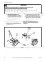
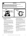
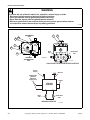
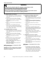
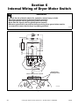
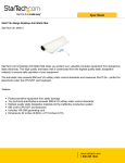
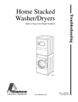
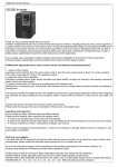
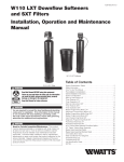
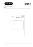
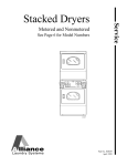
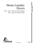
Troubleshooting
Homestyle
Dryers
Refer to Page 6 for Model Numbers
DRY684C
www.comlaundry.com
Part No. 505894R2
March 2012
Table of
Contents
Section 1 – Safety Information
Locating an Authorized Servicer ..................................................... 4
Section 2 – Introduction
Customer Service ............................................................................
Nameplate Location ........................................................................
Model Identification ........................................................................
How Your Dryer Works ..................................................................
5
5
6
7
Section 3 – Troubleshooting
1. Dryer Motor Does Not Run ......................................................
2. Dryer Stops in Cycle; Quits After the First Few Loads;
Has a Burning Smell; Cycles On Motor Thermal Protector .....
3. Dryer Motor Runs But Cylinder Does Not Turn ......................
4. Dryer Motor Does Not Stop .....................................................
5. Dryer Runs Only When Door is Open .....................................
6. Dryer Heating Assembly Does Not Heat or Burner Does
Not Ignite ..................................................................................
7. Igniter Does Not Glow (Gas Supply Sufficient) –
Gas Dryer Models .....................................................................
8. Burner Ignites and Goes Out Repeatedly –
Gas Dryer Models .....................................................................
9. Igniter Glows But Burner Does Not Ignite –
Gas Dryer Models .....................................................................
10. Dryer Heater Assembly or Burner Shuts Off Prematurely .......
11. Dryer Heater Assembly or Burner Repeatedly Cycles
Off On Limit Thermostat ..........................................................
12. Dryer Heater Assembly or Burner Does Not Shut Off .............
13. Clothes Do Not Dry in Dryer ...................................................
14. Timer Does Not Advance in Automatic Cycle .........................
15. Clothes Are Too Hot When Removed From Dryer ..................
16. Excessive Chattering or Vibrating Noise in Dryer ...................
17. Excessive Humming or Whistling Noise in Dryer ...................
18. Ignition Control Flashes ...........................................................
9
11
12
13
14
15
17
18
19
20
21
23
24
25
26
27
28
29
Section 4 – Adjustments
19. Leveling Legs ........................................................................... 31
20. Burner Flame (Gas Models) ..................................................... 32
Section 5 – Test Procedures
21.
22.
23.
24.
25.
26.
Timer Contacts .........................................................................
Fabric Selector Switch ..............................................................
Drive Motor ..............................................................................
Motor Switch ............................................................................
Burner System Operation .........................................................
Electrical Circuit To Ignition System (Gas Models) ................
34
35
36
39
41
43
© Copyright 2012 Alliance Laundry Systems LLC
All rights reserved. No part of the contents of this book may be reproduced or transmitted in any form or by any means without
the expressed written consent of the publisher.
505894
© Copyright, Alliance Laundry Systems LLC – DO NOT COPY or TRANSMIT
1
27.
28.
29.
30.
31.
32.
33.
34.
Gas Valve Coils Check (Gas Models) ......................................
Sensor Check (Gas Models) .....................................................
Igniter Check (Gas Models) .....................................................
Ignition Control Grounding Check
(Silicon Nitride Ignition) ..........................................................
Thermal Fuse (Electric Models) ...............................................
Heater Assembly (Electric Models) .........................................
Cycling or Limit Thermostat ....................................................
Door Switch ..............................................................................
43
44
44
44
44
45
45
45
Section 6 – Internal Wiring of Dryer Motor Switch
2
© Copyright, Alliance Laundry Systems LLC – DO NOT COPY or TRANSMIT
505894
Section 1
Safety Information
Throughout this manual and on machine decals, you will find precautionary statements (“CAUTION,”
“WARNING” and “DANGER”) followed by specific instructions. These precautions are intended for the personal
safety of the operator, user, servicer, and those maintaining the machine.
DANGER
Danger indicates an imminently hazardous situation that, if not avoided, will cause severe personal injury or death.
WARNING
Warning indicates a hazardous situation that, if not avoided, could cause severe personal injury or death.
CAUTION
Caution indicates a hazardous situation that, if not avoided, may cause minor or moderate personal injury or
property damage.
Additional precautionary statements (“IMPORTANT” and “NOTE”) are followed by specific instructions.
IMPORTANT
The word “IMPORTANT” is used to inform the reader of specific procedures where minor machine damage will
occur if the procedure is not followed.
NOTE
The word “NOTE” is used to communicate installation, operation, maintenance or servicing information that is
important but not hazard related.
In the interest of safety, some general precautions relating to the operation of this machine follow.
WARNING
• Failure to install, maintain, and/or operate this machine according to the manufacturer’s
instructions may result in conditions which can produce serious injury, death and/or
property damage.
• Do not repair or replace any part of the machine or attempt any servicing unless specifically
recommended or published in this Service Manual and that you understand and have the
skills to carry out.
• Whenever ground wires are removed during servicing, these ground wires must be
reconnected to ensure that the machine is properly grounded and to reduce the risk of fire,
electric shock, serious injury, or death.
W284
505894
© Copyright, Alliance Laundry Systems LLC – DO NOT COPY or TRANSMIT
3
Section 1 Safety Information
WARNING
To reduce the risk of electric shock, fire, explosion, serious injury or death:
• Disconnect electric power to the dryer(s) before servicing.
• Close gas shut-off valve to gas dryer(s) before servicing.
• Never start the dryer(s) with any guards/panels removed.
• Whenever ground wires are removed during servicing, these ground wires must be
reconnected to ensure that the dryer is properly grounded.
W001R1
WARNING
Repairs that are made to your products by unqualified persons can result in hazards due to
improper assembly or adjustments subjecting you, or the inexperienced person making such
repairs, to the risk of serious injury, electrical shock, or death.
W007
WARNING
If you or an unqualified person perform service on your machine, you must assume the
responsibility for any personal injury or property damage which may result. The manufacturer
will not be responsible for any injury or property damage arising from improper service and/or
service procedures.
W286
NOTE: The WARNINGS and IMPORTANT INSTRUCTIONS appearing in this manual are not meant to
cover all possible conditions and situations that may occur. Common sense, caution and care must be
exercised when installing, maintaining or operating the machine.
Always contact your dealer, distributor, service agent or the manufacturer about any problems or conditions you do
not understand.
Locating an Authorized Servicer
Alliance Laundry Systems is not responsible for personal injury or property damage resulting from improper
service. Review all service information before beginning repairs.
Warranty service must be performed by an authorized technician, using authorized factory parts. If service is
required after the warranty expires, Alliance Laundry Systems also recommends contacting an authorized
technician and using authorized factory parts.
4
© Copyright, Alliance Laundry Systems LLC – DO NOT COPY or TRANSMIT
505894
Section 2
Introduction
Customer Service
If literature or replacement parts are required, contact
the source from whom the machine was purchased or
contact Alliance Laundry Systems at
+1 (920) 748-3950 for the name and address of the
nearest authorized parts distributor.
For technical assistance, call +1 (920) 748-3121.
Nameplate Location
When calling or writing about your product, be sure to
mention model and serial numbers. Model and serial
numbers are located on nameplate(s) as shown.
Nameplate
D412PE1A
505894
© Copyright, Alliance Laundry Systems LLC – DO NOT COPY or TRANSMIT
5
Section 2 Introduction
Model Identification
Information in this manual is applicable to these
dryers:
ADE3TFWS431AW01
ADE3TRWS431AW01
ADE3TRWS431NW22
ADE32FSS431AN01
ADE32FSS431NN22
ADE32FSS541RN01
ADE41FSS171TN03
ADG3TFWS301AW01
ADG3TRWS301AW01
ADG32FSS301AN01
ADG41FSS111TN03
AEZ17A*F1702
AEZ28A*F1702
AEZ68A*F1702
AGZ17A*F1102
AGZ28A*F1102
AGZ68A*F1102
BDE30FGS171CW01
BDG30FGS111CW01
CDE3LRGS171CW01
CDE4BFGS171CW01
CDG3LRGS111CW01
CDG4BFGS111CW01
CEZ68A*F1702
CGZ68A*F1102
FDE3TRGS401NW22
FEN16A*G4018
FEN17A*G3018
FEN17A*G4018
FES16A*G4018
FES17A*F3300
FES17A*F4350
FEU17A*F1702
FEZ17A*F1702
FGN16A*M3013
FGN17A*M3013
FGS17A*F3060
FGZ17A*F1102
LDE3TRWS331TW05
LDG3TRWS111TW05
LEB07A*F1709
LED17A*F1700
LEG37A*F4350
LEH37A*F3300
LEK37A*F4350
LEN27A*G3008
LEN27A*G3018
LEN27A*G4008
LEN27A*G4018
LEN27A*G99M3
LEN37A*G3018
LEN37A*G4018
LES17A*F3000
LES17A*F3007
LES17A*F3022
LES17A*F4500
LES17A*M4588
LES27A*G3018
LES27A*G4000
LES27A*G4500
LES27A*G4518
LES27A*G4018
LES28A*G4018
LES33A*F4562
LES37A*F3000
LES37A*F3028
LES37A*F3300
LES37A*F3327
LES37A*F4350
LES37A*F5412
LES37A*G3018
LES37A*G4018
LET57A*F1700
LET67A*F1700
LET68A*F1700
LEY47A*F1709
LEZ27A*F1702
LEZ27A*G3018
LEZ27A*G4018
LEZ37A*F1702
LEZ37A*F3000
LEZ37A*G3018
LEZ37A*G4018
LEZ37A*G5618
LEZ57A*F1702
LEZ67A*F1702
LGG37A*F3058
LGH37A*F1182
LGH37A*F5423
LGK37A*F3058
LGK37A*F3060
LGN27A*M3008
LGN27A*M3013
LGN37A*M3013
LGS17A*F3020
LGS17A*F3081
LGS17A*K1180
LGS17A*M3020
LGS17A*M3082
LGS27A*M3013
LGS27A*M3080
LGS37A*F3000
LGS37A*F3022
LGS37A*F3028
LGS37A*F3058
LGS37A*F3060
LGS37A*F3080
LGS37A*F5412
LGS37A*F5423
LGS37A*G3013
LGS37A*G3080
LGS37A*M3013
LGS37A*M3080
LGS38A*M3013
LGS38A*M3020
LGS40A*M3020
LGT57A*F1100
LGT68A*F1100
LGY47A*F1109
LGZ27A*F1102
LGZ27A*M3013
LGZ37A*F1102
LGZ37A*F3000
LGZ37A*G3013
LGZ37A*M3013
LGZ57A*F1102
LGZ67A*F1102
MDE3TRWS331TW06
MDG3TRWS111TW06
ZDE30RGS171CW01
ZDE3LRGS171CW01
ZDE41FSS171CN01
ZDE4BFGS171CW01
ZDE4BRGS171CW01
ZDG30RGS111CW01
ZDG3LRGS111CW01
ZDG41FSS111CN01
ZDG4BFGS111CW01
ZDG4BRGS111CW01
* Add Letter To Designate Color. L – Almond W – White Q – Bisque G – Gray
6
© Copyright, Alliance Laundry Systems LLC – DO NOT COPY or TRANSMIT
505894
Section 2 Introduction
How Your Dryer Works
Cylinder
Lint
Filter
Heater
Duct
Blower
Fan
DRY1819S
The dryer uses heated air to dry loads of laundry. When
the motor is started, the exhaust fan pulls room
temperature air in through louvers at the rear of the
dryer and over the heat source (burner flame for gas
and heating element for electric). The heated air moves
through the heater duct and into the cylinder, where it
circulates through the wet load. The air then passes
through the lint filter, air duct, and exhaust fan, where
it is vented to the outdoors.
505894
© Copyright, Alliance Laundry Systems LLC – DO NOT COPY or TRANSMIT
7
Section 3
Troubleshooting
WARNING
To reduce the risk of electric shock, fire, explosion, serious injury or death:
• Disconnect electric power to the dryer(s) before servicing.
• Close gas shut-off valve to gas dryer(s) before servicing.
• Never start the dryer(s) with any guards/panels removed.
• Whenever ground wires are removed during servicing, these ground wires must be
reconnected to ensure that the dryer is properly grounded.
W001R1
IMPORTANT: Refer to wiring diagram for aid in testing dryer components.
8
© Copyright, Alliance Laundry Systems LLC – DO NOT COPY or TRANSMIT
505894
Section 3 Troubleshooting
1. DRYER MOTOR DOES NOT RUN
Dryer motor does not run.
Is power cord
plugged in?
No
Plug in cord.
Yes
Is timer
improperly
set?
Reset timer
or try
another
cycle.
Yes
No
Is timer
inoperative?
Test timer
and
replace if
inoperative.
Yes
No
Is electrical
power off or fuse
blown? Check
laundry room for
blown or loose
fuse(s), or open
circuit
breaker(s). The
dryer itself
doesn't have an
electrical fuse.
Yes
Turn power on or
replace fuse. Check
both fuses for
electric models.
Are motor
starting
functions
inoperative,
does not
start, or motor
just hum?
Yes
Refer to
Adjustments
section to
check motor
switch and
motor
windings.
No
No
Is loading
door closed?
No
Close door.
Yes
No
Yes
Is door switch
inoperative?
Is motor
dead,
won't run?
Refer to
Adjustments
section to
check motor
switch, motor
windings and
main windings.
Yes
Test switch and
replace if
inoperative.
Continued on
next page.
No
SWD1706S-a
SWD1706S-a
505894
© Copyright, Alliance Laundry Systems LLC – DO NOT COPY or TRANSMIT
9
Section 3 Troubleshooting
DRYER MOTOR DOES NOT RUN (CONTINUED)
Continued from
previous page.
Has motor
overload
protector
cycled?
Yes
Wait two or three
minutes for
overload protector
to reset. If
protector cycles
repeatedly, refer
to next flowchart.
Is wiring
broken, loose
or incorrect?
Yes
Refer to wiring
diagram.
Yes
Refer to wiring
diagram for
correct wiring.
No
No
Is motor
centrifugal
switch sticky
or plugged
with lint?
Yes
Remove
dust or lint
and spray
with a
cleaner and
lubricant.
Is power cord
miswired?
No
Is there a bind
in motor
bearing?
No
Is motor wire
harness
connection
block loose?
Yes
Remove belt
and
determine if
motor shaft
will spin.
Replace motor
if shaft is
locked up.
Firmly press
Yes connection
block onto
motor switch.
No
SWD1706S-b
SWD1706S-b
10
© Copyright, Alliance Laundry Systems LLC – DO NOT COPY or TRANSMIT
505894
Section 3 Troubleshooting
2. DRYER STOPS IN CYCLE; QUITS AFTER THE FIRST FEW LOADS; HAS A BURNING SMELL;
CYCLES ON MOTOR THERMAL PROTECTOR
Dryer stops in cycle, quits after first few
loads, has burning smell or cycles on
motor thermal protector.
Is voltage
incorrect?
Yes
No
Is clothes
load too
large?
Yes
No
Is clothes
cylinder
binding?
No
Yes
Refer to nameplate in
door well for correct
voltage. Refer to
Installation
Instructions (supplied
with unit) for
electrical
requirements.
Remove part of
load. A normal
washer load is a
normal dryer load.
Maximum load:
dryer cylinder one
half full of wet
clothes.
Check cylinder for
binding and "out of
round" condition.
Check front and rear
bulkheads for
warping. Check
support rollers for
binding. Check
cylinder seals and
glides for wear or
damage. Check for
clothes lodged
between cylinder
baffle and bulkhead.
Is there
broken, loose
or incorrect
wiring?
Yes
Refer to wiring
diagram.
No
Are motor
switch
functions
inoperative?
Yes
Refer to
Adjustments
section to
check switch
and windings.
No
Is there a
short in
motor
winding?
Yes
Refer to
Adjustments
section to
check switch
and windings.
No
Is a clothes
item caught in
fan?
Yes
Check fan for
obstruction.
SWD1690S
SWD1690S
505894
© Copyright, Alliance Laundry Systems LLC – DO NOT COPY or TRANSMIT
11
Section 3 Troubleshooting
3. DRYER MOTOR RUNS BUT CYLINDER DOES NOT TURN
Dryer motor runs but
cylinder does not turn.
Is motor drive
pulley loose?
Yes
Tighten pulley.
Is belt "inside
out" ?
Yes
Reinstall belt
with ribbed
surface
against
cylinder.
No
No
Is belt
installed on
pulley?
No
Install belt.
Is idler arm
binding?
Yes
Yes
No
Is cylinder
belt broken?
Yes
Replace belt.
Check cylinder for
binding and "out of
round" condition. Check
front and rear
bulkheads for warping.
Check cylinder rollers
for binding. Check
cylinder seals and
glides for wear or
damage.
No
Is clothes
cylinder
binding?
Add grease
between idler
arm and
motor mount.
Replace idler
arm and bolt
if needed.
Yes
No
Is dryer
overloaded?
Yes
Remove some
laundry from
dryer.
No
Is the wrong
motor
installed?
Yes
Refer to parts
manual for
correct motor
part number.
No
Is idler lever
spring broken,
weak or
disconnected?
Yes
Replace or
reconnect
spring.
Is the wrong
belt installed?
No
Is belt routed
on wrong side
of idler lever?
No
Yes
Reroute belt.
Is idler arm
bent?
No
Is there oil on
cylinder?
Check belt
part number
Yes against correct
part number in
parts manual
and replace
belt if needed.
Yes
Yes Replace idler
arm.
Wipe oil from
cylinder.
SWD1691S
SWD1691S
No
12
© Copyright, Alliance Laundry Systems LLC – DO NOT COPY or TRANSMIT
505894
Section 3 Troubleshooting
4. DRYER MOTOR DOES NOT STOP
Dryer motor does not stop.
Is wiring to
motor switch
incorrect?
Yes
Refer to wiring
diagram.
No
Is motor
centrifugal
switch sticky
or plugged
with lint?
Yes
Remove dust or lint
and spray with a
cleaner and
lubricant.
No
Is door switch
inoperative?
Yes
Test switch and
replace if
inoperative.
Yes
Test timer and
replace if
inoperative.
No
Is timer
inoperative?
SWD1707S
SWD1707S
505894
© Copyright, Alliance Laundry Systems LLC – DO NOT COPY or TRANSMIT
13
Section 3 Troubleshooting
5. DRYER RUNS ONLY WHEN DOOR IS OPEN
Dryer runs only when door is
open.
Yes
Is door switch
miswired?
Rewire door
switch. Refer to
wiring diagram.
No
Replace door switch.
SWD1693S
SWD1693S
14
© Copyright, Alliance Laundry Systems LLC – DO NOT COPY or TRANSMIT
505894
Section 3 Troubleshooting
6. DRYER HEATING ASSEMBLY DOES NOT HEAT OR BURNER DOES NOT IGNITE
Dryer heating assembly does not
heat or burner does not ignite.
Is exhaust
system
improper or
inadequate?
Yes
Refer to
Installation
Instructions
(supplied with
unit) for
exhaust
requirements.
Reset
timer. Try
another
cycle.
Yes
No
No
Is exhaust
duct made of
plastic or thin
foil?
Is timer
improperly set
(set in a cooldown period, or
a no heat
cycle)?
Yes
Replace with
rigid or semirigid metal
exhaust duct.
Is limit
thermostat
inoperative?
Test
thermostat
and replace if
inoperative.
Yes
No
No
Is drive
motor switch
inoperative?
Is house fuse
blown or
circuit breaker
tripped?
Yes
Check fuses or
circuit breakers.
Is temperature
selector switch
set at NO
HEAT/AIR
FLUFF, or
inoperative?
No
Electric Models:
Is heater
assembly
inoperative?
No
Yes
Reset or test
switch and
replace if
inoperative.
Test switch
and replace if
inoperative.
Yes
Yes
Test heater
assembly
and replace
if cold
Ohms do
not read
between 9
and 10.5
Ohms.
No
Electric
Models: Is
thermal fuse
inoperative?
Yes
Test thermal
fuse and
replace if
inoperative.
No
No
Continued on
next page.
DRY1866S-a
DRY1866S-a
505894
© Copyright, Alliance Laundry Systems LLC – DO NOT COPY or TRANSMIT
15
Section 3 Troubleshooting
DRYER HEATING ASSEMBLY DOES NOT HEAT OR BURNER DOES NOT IGNITE
(CONTINUED)
Continued from
previous page.
Gas Models:
Is gas supply
insufficient?
Yes
No
Gas Models:
Are gas valve
coils
inoperative?
Yes
Check gas
shut-off valve
in dryer and
main gas line
valve. Open
partially closed
gas shut-off
valve or
correct low
gas pressure.
Test coils and
replace if
inoperative.
Refer to Test
Procedures
section.
Yes
Test sensor
and replace if
inoperative.
Refer to Test
Procedures
section.
No
Gas Models:
Is igniter
inoperative?
Yes
Clean out gas
orifice.
No
Some Gas
Models: Is
high limit
thermostat
tripped?
Yes
Reset
thermostat.
No
No
Gas Models:
Is sensor
inoperative?
Gas Models:
Is gas flow in
gas orifice
restricted?
Is cycling
thermostat
inoperative?
Yes
Test
thermostat
and replace if
inoperative.
No
Yes
Test igniter
and replace if
inoperative.
Refer to Test
Procedures
section.
Is timer
inoperative?
Yes
Test timer
and replace if
inoperative.
No
Gas Models: Is
harness properly
connected to gas
controls?
No
Check
harness
connections
to gas valve
coils, sensor
and main
harness.
Reconnect as
required.
No
Is wiring
broken, loose
or incorrect?
Yes
Refer to wiring
diagram.
Yes
DRY1866S-b
DRY1866S-b
16
© Copyright, Alliance Laundry Systems LLC – DO NOT COPY or TRANSMIT
505894
Section 3 Troubleshooting
7. IGNITER DOES NOT GLOW (GAS SUPPLY SUFFICIENT) – GAS DRYER MODELS
Gas dryer models: Igniter
does not glow (gas supply
sufficient).
Is there power to
power leads on
valve?
No
Check timer,
thermostats,
motor switch
and wiring.
Yes
Has sensor
failed with
contacts
open?
Yes
Replace sensor.
No
Is igniter broken
or open?
Yes
Replace igniter.
DRY1867S
DRY1867S
505894
© Copyright, Alliance Laundry Systems LLC – DO NOT COPY or TRANSMIT
17
Section 3 Troubleshooting
8. BURNER IGNITES AND GOES OUT REPEATEDLY – GAS DRYER MODELS
Gas dryer models: Burner ignites
and goes out repeatedly.
Is exhaust
system
improper or
inadequate?
Yes
Refer to
Installation
Instructions
(supplied with
unit) for
exhaust
requirements.
Is igniter
cracked?
Yes
Replace igniter
and bracket.
No
No
Is weather
hood flapper
restricted?
Yes
Refer to
Installation
Instructions
(supplied with
unit) for
exhaust
requirements.
Are gas valve
coils
inoperative or
intermittent?
Check coils and
replace
Yes appropriate coils.
Refer to Dryer
Test Procedures
section.
No
Silicon Carbide
Ignition: Is burner
heat holding
sensor contacts
open?
No Replace sensor
or correct gas
supply problem.
Yes
Is gas supply
insufficient?
Yes
Check gas supply
and pressure.
Make sure gas
shut-off valve is
turned on.
No
DRY1868S
DRY1868S
18
© Copyright, Alliance Laundry Systems LLC – DO NOT COPY or TRANSMIT
505894
Section 3 Troubleshooting
9. IGNITER GLOWS BUT BURNER DOES NOT IGNITE – GAS DRYER MODELS
Gas dryer models: Igniter glows but
burner does not ignite.
Silicon Carbide
Ignition: Did
sensor fail in
closed position?
Yes
Replace sensor.
Are igniter
and bracket
improperly
installed on
burner tube
assembly?
Yes
Loosen screw and
properly position
igniter and bracket
on burner tube
assembly.
No
No
Is secondary
coil or holding
coil open?
Yes
No
Is gas supply
insufficient?
Yes
Replace gas
valve (in
warranty) or
replace coils
(out of
warranty). Refer
to Test
Procedures
section.
Silicon
Carbide
Ignition: Is
sensor
improperly
installed on
burner
housing?
Yes
Loosen screw
and properly
position the
sensor on the
burner housing.
Check gas
supply and
pressure. Make
sure gas shutoff valve is
turned on.
No
DRY1869S
DRY1869S
505894
© Copyright, Alliance Laundry Systems LLC – DO NOT COPY or TRANSMIT
19
Section 3 Troubleshooting
10. DRYER HEATER ASSEMBLY OR BURNER SHUTS OFF PREMATURELY
Dryer heater assembly or burner
shuts off prematurely.
Is exhaust
system
improper or
inadequate?
Refer to
Installation
Instructions
(supplied with
unit) for
exhaust
requirements.
Yes
Cycling off on
limit
thermostat?
No
No
Is weather
hood flapper
restricted?
Momentarily
connect a
jumper wire
across
thermostat
Yes terminals. If
heater element
heats or burner
ignites when
jumper wire is
connected, refer
to next flowchart.
Refer to
Installation
Instructions
(supplied with
unit) for
exhaust
requirements.
Yes
Replace sensor
Yes or adjust burner
flame (refer to
Adjustments
section).
Gas Models: Is
sensor contact
closing?
No
Gas Models: Is
gas supply
insufficient?
Yes
Check main gas
line shut-off
valve. Open
partially closed
gas shut-off
valve or correct
low pressure.
No
Is cycling
thermostat
inoperative?
Yes
Test thermostat
and replace if
inoperative.
No
No
Gas Models: Is
dryer properly
equipped for type
of gas used?
No
Refer to "Gas
Burner Conversion
Procedures"
supplied in gas
burner conversion
kit.
Is timer
inoperative?
Yes
Test timer and
replace if
inoperative.
No
Yes
Gas Models:
Is burner
flame
improperly
adjusted?
Yes
Adjust flame.
Refer to
Adjustments
section.
Is wiring
broken, loose
or incorrect?
Yes
Refer to wiring
diagram.
SWD1709S
SWD1709S
No
20
© Copyright, Alliance Laundry Systems LLC – DO NOT COPY or TRANSMIT
505894
Section 3 Troubleshooting
11. DRYER HEATER ASSEMBLY OR BURNER REPEATEDLY CYCLES OFF ON LIMIT
THERMOSTAT
Dryer heater assembly or burner repeatedly
cycles off on limit thermostat.
Is external exhaust
system longer or
providing greater
restriction than
recommended?
Yes
Refer to
Installation
Instructions
(supplied with
unit) for
exhaust system
requirements.
Is there lint
or other
obstruction in
external
exhaust
system?
Yes
Disassemble
and clean
exhaust
system.
No
No
Is exhaust duct
made of plastic
or thin foil?
Yes
Replace with rigid
or semi-rigid metal
exhaust duct.
No
Is lint filter
clogged?
Yes
Clean lint
filter.
Is hinged
damper on
exhaust system
weather hood
not free to
open?
Free hinged
Yes damper or
replace
weather
hood.
No
No
Is there lint in
internal dryer
ductwork?
Yes
Disassemble
dryer ductwork
and clean.
Is limit
thermostat
cycling at too
low a
temperature?
Yes
Replace
thermostat.
No
No
Continued on
next page.
SWD1710S-a
SWD1710S-a
505894
© Copyright, Alliance Laundry Systems LLC – DO NOT COPY or TRANSMIT
21
Section 3 Troubleshooting
DRYER HEATER ASSEMBLY OR BURNER REPEATEDLY CYCLES OFF ON LIMIT
THERMOSTAT (CONTINUED)
Continued from
previous page.
Is there an air leak
around loading door?
(Door not sealing due
to damaged seal or
inoperative door
catch)?
Yes Replace seal
or catch.
Is there an air
leak at front
panel seal?
Yes
Check and
replace seal if
necessary.
No
Is there an air
leak at blower
seal?
Yes
Check and
replace seal if
necessary.
No
Is there an air
leak at cylinder
seal(s)?
Yes
Check and
replace seal(s)
if necessary.
No
SWD1710S-b
SWD1710S-b
22
© Copyright, Alliance Laundry Systems LLC – DO NOT COPY or TRANSMIT
505894
Section 3 Troubleshooting
12. DRYER HEATER ASSEMBLY OR BURNER DOES NOT SHUT OFF
Dryer heater assembly or
burner does not shut off.
Is motor switch
inoperative?
(Must be in a
heat setting.)
Yes
Test switch and
replace if
inoperative.
No
Motor does
not stop?
Yes
Refer to Dryer
Motor Does Not
Stop paragraph.
No
Is wiring
incorrect?
Yes
Refer to wiring
diagram.
No
Has heater
assembly
shorted?
Yes
Remove heater
assembly and
check for short.
SWD1700S
SWD1700S
505894
© Copyright, Alliance Laundry Systems LLC – DO NOT COPY or TRANSMIT
23
Section 3 Troubleshooting
13. CLOTHES DO NOT DRY IN DRYER
Clothes do not dry in dryer.
Adjust timer
knob to More
Dry setting.
Yes
Automatic Cycle?
Does heater
assembly not
heat or
burner not
ignite?
Yes
Refer to Dryer
Heating
Assembly Does
Not Heat or
Burner Does
Not Ignite
paragraph.
Is fabric selector
switch or timer set on
NO HEAT/FLUFF or
inoperative?
Yes
Test and
replace switch
or timer if
inoperative.
No
No
Is there too
much water
in articles
being dried?
No
Yes
Remove
excess water.
Is exhaust
system
improper or
inadequate?
Yes
Refer to
Installation
Instructions
(supplied with
unit) for exhaust
requirements.
No
No
Is laundry
load too
large?
Yes
No
Is laundry
load too
small?
Yes
Remove part of
load. A normal
washer load is a
normal dryer
load. Maximum
load: Dryer
cylinder one half
full of wet
clothes.
Add one or two
bath towels to
load.
Does heater
assembly or
burner shut off
prematurely?
Yes
No
Gas Models: Is
gas line
pressure too
high or too low?
Yes
No
Is there
excessive
lint on lint
filter?
No
Yes
Refer to Dryer
Heater
Assembly or
Burner Shuts
Off Prematurely
paragraph.
If Natural Gas
line pressure to
dryer exceeds 8
inch water
column
pressure, or is
lower than 5
inch water
column, ask Gas
Company to
correct.
No
Clean lint
filter.
Is belt installed
improperly (low
RPM)?
Yes
Check for
proper
installation.
DRY1870S
DRY1870S
24
© Copyright, Alliance Laundry Systems LLC – DO NOT COPY or TRANSMIT
505894
Section 3 Troubleshooting
14. TIMER DOES NOT ADVANCE IN AUTOMATIC CYCLE
Timer does not advance in
automatic cycle.
Is cycling
thermostat
inoperative?
Yes
Test thermostat
and replace if
inoperative.
Test resistor
and replace if
inoperative.
Yes
Yes
Refer to Dryer
Heating
Assembly Does
Not Heat or
Burner Does
Not Ignite
paragraph.
No
Heater assembly
or burner cycles
off prematurely?
Refer to Dryer
Heater
Yes Assembly or
Burner Shuts
Off Prematurely
paragraph.
No
Is exhaust
system
improper or
inadequate?
Refer to
Installation
Yes Instructions
(supplied with unit)
for exhaust
requirements.
Yes
Refer to wiring
diagram.
Is timer
motor
inoperative?
No
Are seals
inoperative
(air leaks)?
Select a drying
cycle and activate
start switch. Rotate
timer knob until
Yes signal sounds.
Release timer
knob. Signal should
stop within ten
minutes. If not,
replace timer.
Yes
Check and replace any
inoperative seals in the
following areas:
1. Seal between loading
door and front panel.
2. Seal between front panel
and front bulkhead.
3. Seal between blower
cover and air duct.
4. Seal between cylinder
and front or rear bulkhead.
5. Gap between air duct and
filter mounting.
SWD1712S
SWD1712S
No
505894
Timer will not
advance until
the load is
almost dry.
No
No
Heater
assembly
does not heat
or burner does
not ignite?
Yes
No
Is wiring
broken,
loose or
incorrect?
No
Electric
Models: Is
resistor
inoperative?
Is large
load
drying?
© Copyright, Alliance Laundry Systems LLC – DO NOT COPY or TRANSMIT
25
Section 3 Troubleshooting
15. CLOTHES ARE TOO HOT WHEN REMOVED FROM DRYER
Clothes are too hot when
removed from dryer.
Is exhaust
system
improper or
inadequate?
Yes
Refer to
Installation
Instructions
(supplied with unit)
for exhaust
requirements.
No
Is timer
inoperative
(not allowing
cool-down)?
Yes Test timer and
replace if
inoperative.
No
Were clothes
removed from
dryer before
cycle has
completed?
Yes
Allow the dryer to
complete the
cycle through the
cool-down to the
OFF position.
No
Is cycling
thermostat
inoperative?
Yes
Test cycling
thermostat and
replace if
inoperative.
No
Is thermostat
heater
inoperative on
DELICATE/
KNITS setting?
Are seals
inoperative
(air leaks)?
Yes
Check and replace any inoperative
seals in the following areas:
1. Seal between loading door and
front panel.
2. Seal between front panel and
front bulkhead.
3. Seal between blower cover and
air duct.
4. Seal between cylinder and front
or rear bulkhead.
5. Gap between air duct and filter
mounting.
Test thermostat
Yes heater and
replace if
inoperative.
No
DRY1871S
DRY1871S
26
© Copyright, Alliance Laundry Systems LLC – DO NOT COPY or TRANSMIT
505894
Section 3 Troubleshooting
16. EXCESSIVE CHATTERING OR VIBRATING NOISE IN DRYER
Excessive chattering or
vibrating noise in dryer.
Yes
Is idler spring
inoperative?
Remove lower access panel. Set
dryer to normal cycle and allow it
to heat to operating temperature.
If the belt vibrates as it rotates
around the cylinder, the idler
arm is making the noise. Replace
the idler spring.
No
Check blower fan
for missing or
cracked fan blades.
SWD1703S
SWD1703S
505894
© Copyright, Alliance Laundry Systems LLC – DO NOT COPY or TRANSMIT
27
Section 3 Troubleshooting
17. EXCESSIVE HUMMING OR WHISTLING NOISE IN DRYER
Excessive humming or
whistling noise in dryer.
Is blower
housing
inoperative?
Yes
If the abnormal operating noise is
loudest at the vent exit, the
problem is originating from the
blower housing. Replace the
current housing and cover.
No
Check blower fan
for missing or
cracked fan blades.
SWD1704S
SWD1704S
28
© Copyright, Alliance Laundry Systems LLC – DO NOT COPY or TRANSMIT
505894
Section 3 Troubleshooting
WARNING
To reduce the risk of electric shock, fire, explosion, serious injury or death:
• Disconnect electric power to the dryer(s) before servicing.
• Close gas shut-off valve to gas dryer(s) before servicing.
• Never start the dryer(s) with any guards/panels removed.
• Whenever ground wires are removed during servicing, these ground wires must be
reconnected to ensure that the dryer is properly grounded.
W001R1
18. IGNITION CONTROL FLASHES
Refer to Figure 1.
NOTE: This control will lock-out the igniter after four
failed attempts at ignition. The control can be reset
by opening loading door, waiting 1 minute, then
closing loading door. If door is closed before waiting
1 minute, the control will re-enter lockout. The red
light will flash a “Flash Code” when the control is in
the lock-out mode. The light will flash on for 1/4
second then off for 1/4 second for each number. The
pause between flash codes is 2 seconds. These flashes
are caused by the control’s diagnostic test and can be
interpreted by reading the following:
FLASH CODE
Constant Light
POSSIBLE CAUSE
Internal failure.
One Flash
Air in gas line.
Sensor coated with Aluminum Oxide.
Incorrect gas pressure.
Four Flashes
Gas shut-off valve closed.
Internal failure.
Loose or disconnected wiring.
Five Flashes
Open Igniter/igniter sensing circuit/
voltage measurement circuit.
Loose or disconnected wiring.
Six Flashes
Inoperative gas valve.
Inoperative sensor.
Loose or disconnected wiring.
Incorrect wiring.
Incorrect polarity.
505894
TO CORRECT
• Reset dryer. (Refer to NOTE above.) If
condition persists, then replace control.
• Purge air from gas line.
• Wipe sensor clean or replace sensor if
necessary.
• Check for correct gas pressure. If gas pressure
is incorrect, then contact local gas company.
• Open gas shut-off valve.
• Reset dryer. If condition persists, then replace
control.
• Check all wiring leading to, or coming from,
the control module for secure connections.
• Check igniter and all circuits, replace if
necessary.
• Check all wiring leading to, or coming from,
the control module for secure connections.
• Check gas valve and replace if necessary.
• Replace sensor/igniter.
• Check all wiring leading to, or coming from,
the control module for secure connections.
• Check wiring diagram and make sure dryer is
wired correctly.
• Contact a professional electrician to check the
polarity, and correct any problems.
© Copyright, Alliance Laundry Systems LLC – DO NOT COPY or TRANSMIT
29
Section 3 Troubleshooting
WARNING
To reduce the risk of electric shock, fire, explosion, serious injury or death:
• Disconnect electric power to the dryer(s) before servicing.
• Close gas shut-off valve to gas dryer(s) before servicing.
• Never start the dryer(s) with any guards/panels removed.
• Whenever ground wires are removed during servicing, these ground wires must be
reconnected to ensure that the dryer is properly grounded.
W001R1
IGNITION CONTROL FLASHES (continued)
FLASH CODE
Seven Flashes
POSSIBLE CAUSE
Loose or disconnected wiring.
Rapid Flashing
Sensor and/or appliance not properly
grounded.
Incorrect frequency.
TO CORRECT
• Check all wiring leading to, or coming from,
the control module for secure connections.
• Check grounding from control to base, and
from lead in cord to dryer.
• Contact a professional electrician to check the
frequency, and correct any problems. Power
supply must be 50 – 60 Hz. 2-wire, plus
grounding (earth) wire.
WR
WR
IMPORTANT
WHITE - ROGERS DIV.
DISCONNECT POWER BEFORE
SERVICING SERVICEING OK
MODEL 50A72-203.
EMERSON ELECTRIC CO.
DISCONNECT POWER BEFORE
SERVICINGGDGHDHJD DHJD DHD HD
HD HD HDGFJGFKGK GFJHGJ FHFH
F KJFJF KH GJHJF JDAPALS DK KF
DISCONNECT POWER
BEFORE SERVICING
DISCONNECT POWER
BEFORE SERVICING
DISCONNECT POWER
BEFORE SERVICING
DISCONNECT POWER
BEFORE SERVICING
WARNING
DIAGNOSTIC INDICATOR
DISCONNECT POWER
BEFORE SERVICING
DISCONNECT POWER
BEFORE SERVICING
DISCONNECT POWER
BEFORE SERVICING
Control
Red
Light
D194SE3D
Figure 1
30
© Copyright, Alliance Laundry Systems LLC – DO NOT COPY or TRANSMIT
505894
Section 4
Adjustments
WARNING
To reduce the risk of electric shock, fire, explosion, serious injury or death:
• Disconnect electric power to the dryer(s) before servicing.
• Close gas shut-off valve to gas dryer(s) before servicing.
• Never start the dryer(s) with any guards/panels removed.
• Whenever ground wires are removed during servicing, these ground wires must be
reconnected to ensure that the dryer is properly grounded.
W001R1
IMPORTANT: When reference is made to
directions (right or left) in this manual, it is from
operator’s position facing front of washer.
NOTE: Legs can be adjusted outside the dryer by
using a 1-1/4 inch size wrench, or from inside the
dryer (with lower front access panel removed) by
using a 1/4 inch drive ratchet with extension.
19. LEVELING LEGS
Refer to Figure 2.
b. Keep dryer as close to the floor as possible. All
four legs must rest firmly on the floor so weight
of the dryer is evenly distributed. The dryer
MUST NOT rock.
NOTE: Dryer should be installed on a solid and
level floor.
a. Place dryer in position, adjusting the legs until
dryer is level.
WARNING
IMPORTANT: DO NOT move the dryer at any time
unless the dryer is completely assembled. DO NOT
slide the dryer across the floor once the leveling legs
have been extended as the legs and base could
become damaged.
To reduce the risk of serious injury or death
by carbon monoxide and other gases in gas
dryers, carefully read and follow all
instructions given in this section.
W005
Dryer
Base
Leveling
Leg
D351S
Figure 2
505894
© Copyright, Alliance Laundry Systems LLC – DO NOT COPY or TRANSMIT
31
Section 4 Adjustments
WARNING
To reduce the risk of electric shock, fire, explosion, serious injury or death:
• Disconnect electric power to the dryer(s) before servicing.
• Close gas shut-off valve to gas dryer(s) before servicing.
• Never start the dryer(s) with any guards/panels removed.
• Whenever ground wires are removed during servicing, these ground wires must be
reconnected to ensure that the dryer is properly grounded.
W001R1
20. BURNER FLAME (Gas Models)
a. While supporting the access panel, remove two
screws from bottom edge of access panel. Refer
to Figure 8.
b. Gently lower the access panel to disengage
locators from bottom edge of front panel. Refer
to Figure 17.
c. Set timer to 60 minutes.
d. Close the loading door. Start the dryer in a heat
setting (refer to Operating Instructions supplied
with the dryer). The dryer will start, the igniter
will glow red, and the main burner will ignite.
e. Allow the dryer to operate for approximately
five minutes, then loosen the air shutter
lockscrew. Refer to Figure 3.
32
f. Turn the air shutter to the left to get a luminous
yellow tipped flame, then turn it back slowly to
the right to obtain a steady blue flame.
g. After proper flame is obtained, tighten air
shutter lockscrew firmly. Refer to Figure 3.
h. Reinstall access panel and screws.
WARNING
To reduce the risk of fire or serious injury,
the access panel must be in place during
normal operation.
W262
NOTE: After the dryer has operated for
approximately three minutes, exhaust air or
exhaust pipe should be warm.
© Copyright, Alliance Laundry Systems LLC – DO NOT COPY or TRANSMIT
505894
Section 4 Adjustments
SHUT-OFF
VALVE
HANDLE
AIR SHUTTER
LOCKSCREW
AIR
SHUTTER
D265SE3A
1/8" PIPE PLUG
(For checking manifold pressure)
SILICON CARBIDE IGNITION SYSTEM
Air Shutter
Lockscrew
Shut-Off Valve
Handle
(Shown in Open Position)
WR
Air
Shutter
1/8" Pipe Plug
(For checking manifold pressure)
D363SE3A
SILICON NITRIDE IGNITION SYSTEM
Figure 3
505894
© Copyright, Alliance Laundry Systems LLC – DO NOT COPY or TRANSMIT
33
Section 5
Test Procedures
WARNING
To reduce the risk of electric shock, fire, explosion, serious injury or death:
• Disconnect electric power to the dryer(s) before servicing.
• Close gas shut-off valve to gas dryer(s) before servicing.
• Never start the dryer(s) with any guards/panels removed.
• Whenever ground wires are removed during servicing, these ground wires must be
reconnected to ensure that the dryer is properly grounded.
W001R1
IMPORTANT: Electrical test procedures in this
service manual are performed by using a Volt-Ohm
meter. Tests can also be performed using a multimeter or any other electrical testing equipment with
which the service person is familiar.
b. Manually rotate timer out of “OFF” position
and into cycle.
c. Set test meter to read Ohms. The following
readings should be found:
(1) Motor circuit test – L1 and M = “zero”
Ohms (closed)
(2) Heat circuit test – L2 and H = “zero” Ohms
(closed)
(3) Timer motor test – T and M (1702 and1709
suffix models) or T and N (all other
models) = approximately 2462-2714 Ohms
or apply live power to timer motor
terminals and motor should run.
21. TIMER CONTACTS
Refer to Figure 4.
a. Disconnect wires from timer, except timer
motor wires.
NOTE: Refer to appropriate wiring diagram when
rewiring timer.
“M”
“H”
No. 270
“M”
“L2”
T
M
T
P/B
H
S
XXX VAC
N
H
P/B
S
L1 P/B
A
S
L1 P/B
“L2”
RSPC
MODEL 275BEF
XXX VAC
3 WATT
“L1”
TM
MOD
60-1
NGSTON
KI
RSPC
MODEL 275BEF
3 WATT
“L1”
TM
MOD
60-1
NGSTON
KI
XXX VAC
Timer Motor
Wires
NGSTON
KI
3 WATT
Timer Motor
Wires
DRY1825S
MODELS WITH 80+ MINUTES
IN TIME DRY CYCLE
P/B
M
A
“L2”
Timer Motor
Wires
N
R
H
L2
L2
T
M
R
L1 P/B
RSPCª
MODEL 275BEF
“M”
L3
L2
L2
“L1”
MOD
60-1
No. 270
L3
N
L2
“H”
“H”
No. 270
DRY1827S
1702 AND 1709 SUFFIX MODELS
WITH 70+ MINUTES IN
TIME DRY CYCLE
DRY1826S
ALL OTHER MODELS
WITH 70+ MINUTES IN
TIME DRY CYCLE
Figure 4
34
© Copyright, Alliance Laundry Systems LLC – DO NOT COPY or TRANSMIT
505894
Section 5 Test Procedures
WARNING
To reduce the risk of electric shock, fire, explosion, serious injury or death:
• Disconnect electric power to the dryer(s) before servicing.
• Close gas shut-off valve to gas dryer(s) before servicing.
• Never start the dryer(s) with any guards/panels removed.
• Whenever ground wires are removed during servicing, these ground wires must be
reconnected to ensure that the dryer is properly grounded.
W001R1
NOTE: Timer Motor Resistance:
120 Volt, 60 Hz
2,462 – 2,714 Ohms
240 Volt
10,900 – 13,300 Ohms
24 Volt
108 – 132 Ohms
(4) Rotate timer to “cooldown” (5 minutes
before “OFF”). “Infinite” (open) reading
should be found between L2 and H.
(5) Rotate timer to “OFF” position. “Infinite”
(open) reading should be found between L1
and M and between L2 and H.
NOTE: Timer motor power is supplied through M
(1702 and1709 models) or N (all other models)
terminal.
22. FABRIC SELECTOR SWITCH
NOTE: Refer to proper model wiring diagram
when rewiring switch.
a. Set test meter to read Ohms and apply meter
probes to switch terminals.
NOTE: Refer to proper model wiring diagram
when reconnecting wires.
FABRIC SELECTOR SWITCH – 4 Position
L1-1
L1-2
No Heat/Air Fluff
–
–
Delicate
X
X
Perm. Press
–
X
Regular
–
X
X indicates closed
FABRIC SELECTOR SWITCH – 3 Position
L1-2
L1-3
No Heat/Air Fluff
–
X
Delicate/Knits
X
–
Regular/Perm. Press
X
–
X indicates closed
505894
© Copyright, Alliance Laundry Systems LLC – DO NOT COPY or TRANSMIT
L1-1
–
X
–
35
Section 5 Test Procedures
WARNING
To reduce the risk of electric shock, fire, explosion, serious injury or death:
• Disconnect electric power to the dryer(s) before servicing.
• Close gas shut-off valve to gas dryer(s) before servicing.
• Never start the dryer(s) with any guards/panels removed.
• Whenever ground wires are removed during servicing, these ground wires must be
reconnected to ensure that the dryer is properly grounded.
W001R1
23. DRIVE MOTOR
Refer to Figure 5.
a. Remove motor and exhaust assembly. Refer to
Paragraph 51.
b. Disconnect motor wire harness at motor
disconnect block.
NOTE: Refer to wiring schematic, Section 8, for
internal motor switch wires.
NOTE: Drive Motor Resistance
120 Volt
2,460 – 3,100 Ohms
240 Volt
10,000 - 13,000 Ohms
MOTOR
SWITCH
MOTOR AND
EXHAUST
ASSEMBLY
4
3
5
1
MOTOR
DISCONNECT
BLOCK
1
4
3
G
2
6
5
2 6
DRIVE
MOTOR
D326SE3A
Figure 5
36
© Copyright, Alliance Laundry Systems LLC – DO NOT COPY or TRANSMIT
505894
Section 5 Test Procedures
WARNING
To reduce the risk of electric shock, fire, explosion, serious injury or death:
• Disconnect electric power to the dryer(s) before servicing.
• Close gas shut-off valve to gas dryer(s) before servicing.
• Never start the dryer(s) with any guards/panels removed.
• Whenever ground wires are removed during servicing, these ground wires must be
reconnected to ensure that the dryer is properly grounded.
W001R1
c. Motor Switch (Refer to SECTION 8 for Internal Wiring of the Dryer Motor Switch.)
WARNING
Disconnect electric power to dryer before performing any of the following
steps or when replacing inoperative motor switch.
W290
Unplug the motor wire harness from the motor
connection block before starting this test.
Start Terminals
Note: Disconnect
terminal 5 wire (yellow
or copper) from motor
switch before testing
start terminals.
Run Terminals
Note: Reconnect
terminal 5 wire (yellow
or copper) to motor
switch before testing run
terminals.
Heater Circuit Terminals
A. Continuity exists between switch
terminal 5 and terminal 3 (black or
copper wire).
NO
YES
B. Manually depress actuator.
Continuity broken between switch
terminal 5 and terminal 3 (black or
copper wire).
NO
Inoperative start
switch. Replace switch.
Refer to Section 5.
YES
C. Continuity broken between switch
terminal 6 and terminal 5 (yellow or
copper wire).
YES
NO
D. Manually depress actuator.
Continuity exists between switch
terminal 6 and terminal 5 (yellow or
copper wire).
NO
YES
E. Continuity broken between switch
terminal 1 and switch terminal 2.
Inoperative start
switch. Replace switch.
Refer to Section 5.
NO
YES
F. Manually depress actuator.
Continuity exists between switch
terminal 1 and switch terminal 2.
NO
Inoperative start
switch. Replace switch.
Refer to Section 5.
YES
Motor switch checks O.K.
505894
© Copyright, Alliance Laundry Systems LLC – DO NOT COPY or TRANSMIT
37
Section 5 Test Procedures
WARNING
To reduce the risk of electric shock, fire, explosion, serious injury or death:
• Disconnect electric power to the dryer(s) before servicing.
• Close gas shut-off valve to gas dryer(s) before servicing.
• Never start the dryer(s) with any guards/panels removed.
• Whenever ground wires are removed during servicing, these ground wires must be
reconnected to ensure that the dryer is properly grounded.
W001R1
d. Motor Windings (Refer to SECTION 8 for Internal Wiring of the Dryer Motor Switch.)
WARNING
Disconnect electric power to dryer before performing any of the following
steps or when replacing inoperative motor switch.
W290
Start Winding
G. 1 – 2 Ohms between terminal
3 wire and orange or copper
wire on the back of switch.
NO
Inoperative start winding.
Replace motor. Refer to
Paragraph 51.
YES
Run Main Winding
H. 1 – 2 Ohms between terminal 5
wire and orange or copper wire
on the back of switch wire.
NO
Inoperative run main
winding. Replace motor.
Refer to Paragraph 51.
YES
Protector
I.
Continuity exists between
orange or copper wire on back
of switch and brown or blue
wire in terminal 4.
NO
Inoperative protector.
Replace motor.
Refer to Paragraph 51.
YES
All motor windings check O.K.
38
© Copyright, Alliance Laundry Systems LLC – DO NOT COPY or TRANSMIT
505894
Section 5 Test Procedures
WARNING
To reduce the risk of electric shock, fire, explosion, serious injury or death:
• Disconnect electric power to the dryer(s) before servicing.
• Close gas shut-off valve to gas dryer(s) before servicing.
• Never start the dryer(s) with any guards/panels removed.
• Whenever ground wires are removed during servicing, these ground wires must be
reconnected to ensure that the dryer is properly grounded.
W001R1
24. MOTOR SWITCH
a. Remove motor and exhaust fan assembly. Refer
to Paragraph 51.
b. Remove the two motor switch attaching screws.
Refer to Figure 10. Disconnect switch leads.
Remove motor switch.
c. Remove thermal overload protector.
NOTE: The thermal overload protector is unique to
the motor from which it was removed and should
only be used on that motor. To reduce the risk of
overheating the motor, do not use any thermal
overload protector other than the one taken from
the inoperative motor switch in step 3.
(1) Motor with Switch on Blower End
Using a small bladed screwdriver, press the
thermal overload protector mounting tab
downward and remove the thermal
overload protector from the inoperative
motor switch. Refer to Figure 6.
Mounting
Tab
Thermal
Overload
Protector
Motor
Switch
D029KE3A
Figure 6
505894
© Copyright, Alliance Laundry Systems LLC – DO NOT COPY or TRANSMIT
39
Section 5 Test Procedures
WARNING
To reduce the risk of electric shock, fire, explosion, serious injury or death:
• Disconnect electric power to the dryer(s) before servicing.
• Close gas shut-off valve to gas dryer(s) before servicing.
• Never start the dryer(s) with any guards/panels removed.
• Whenever ground wires are removed during servicing, these ground wires must be
reconnected to ensure that the dryer is properly grounded.
W001R1
(2) Motor with switch on pulley end
Press the tip of a small bladed screwdriver
into the slot located between top of motor
switch and plastic clip. Lift up on handle of
screwdriver until both clip and thermal
overload protector detach from motor
switch. Refer to Figure 7.
d. Attach the thermal overload protector removed
in Step “c” to the new motor switch.
e. Install new motor switch onto motor and
reconnect motor switch leads removed in Step
“b”. Refer to Figure 10.
f. Test motor switch by following the step-bystep procedures included in Paragraph 23.
g. Before reinstalling the motor assembly, apply
power (120 VAC) directly to motor terminals 4
and 5. Then start and run the motor at least 6
times, making sure the motor and switch are
operating properly.
NOTE: The dryer manufacturer and parts
suppliers are not liable for improper switch
installation.
Thermal
Overload
Protector
Plastic
Clip
Top Of
Motor
Switch
Motor
Switch
D359SE3A
Figure 7
40
© Copyright, Alliance Laundry Systems LLC – DO NOT COPY or TRANSMIT
505894
Section 5 Test Procedures
WARNING
To reduce the risk of electric shock, fire, explosion, serious injury or death:
• Disconnect electric power to the dryer(s) before servicing.
• Close gas shut-off valve to gas dryer(s) before servicing.
• Never start the dryer(s) with any guards/panels removed.
• Whenever ground wires are removed during servicing, these ground wires must be
reconnected to ensure that the dryer is properly grounded.
W001R1
4
SECONDARY
COIL
5
1
2
3
HOLDING COIL
AND
BOOSTER COIL
(SPLIT COIL VALVE)
120 VOLT, 60 HERTZ
ELECTRICAL
SUPPLY LINE
SECONDARY
COIL
SENSOR
HOLDING
COIL
BOOSTER
COIL
D267SE3B
IGNITOR
D268SE3A
Figure 8
25. BURNER SYSTEM OPERATION
(Gas Models – Refer to Figure 8.)
a. Components
This burner has four basic components: a
silicon carbide (glow bar) igniter, burner tube,
sensor, and a two-stage gas valve consisting of
a split-coil valve and a secondary coil valve.
The split-coil valve is opened when the dryer
thermostat calls for heat, while the secondary
valve does not open until the igniter has attained
ignition temperature.
b. Pre-Ignition Circuits
When the dryer thermostat calls for heat,
circuits are completed through the holding coil,
sensor, booster coil and igniter. Both coils must
be energized to open the split-coil valve. Once
opened, the holding coil can hold the valve
open without assistance from the booster coil.
The sensor triggers the current to travel around
the secondary coil and through the igniter,
causing the igniter to get hot.
c. Burner Circuit
In approximately 30 seconds, the igniter attains
ignition temperature and ignition is made. The
heat from the burner flame causes the sensor
contacts (located on burner housing beside the
igniter) to open. A circuit is then completed
505894
through the secondary valve coil, opening the
valve and allowing gas to flow.
d. Momentary Power Interruption
Upon resumption of power, sensor contacts will
still be open, permitting secondary valve to
open. However, with the secondary coil in the
circuit, the booster coil cannot draw enough
current to open the split-coil valve. When
sensor contacts do reclose, the secondary valve
will close, and the burner system will be in the
normal pre-ignition circuit.
e. Flame Failure
In case of flame failure, the sensor contacts will
re-close in about 45 seconds. This will close the
secondary valve and the burner system will be
in the normal pre-ignition circuit.
f. Ignition Failure
If flame is not established as sensor contacts
open, secondary valve will remain open until
sensor contacts re-close. Sensor will continue to
recycle the igniter and secondary valve (about
once per minute) until ignition is made or dryer
is turned off.
© Copyright, Alliance Laundry Systems LLC – DO NOT COPY or TRANSMIT
41
Section 5 Test Procedures
WARNING
To reduce the risk of electric shock, fire, explosion, serious injury or death:
• Disconnect electric power to the dryer(s) before servicing.
• Close gas shut-off valve to gas dryer(s) before servicing.
• Never start the dryer(s) with any guards/panels removed.
• Whenever ground wires are removed during servicing, these ground wires must be
reconnected to ensure that the dryer is properly grounded.
W001R1
4
5
SECONDARY
COIL
1
2
4 5
1
2
1 - 3
Main
Coil
3
Redundant
Coil
D270SE3A
HOLDING
AND BOOSTER
COIL
D340SE3A
GAS VALVE FOR SILICON NITRATE IGNITION
Flame
Sensor
Ground
220/240 Volt,
50 Hertz
Electrical
Supply Line
Igniter
IGNITION
CONTROL
Main
Coil
Redundant
Coil
WIRING SCHEMATIC
D332SE3A
Figure 9
42
© Copyright, Alliance Laundry Systems LLC – DO NOT COPY or TRANSMIT
505894
Section 5 Test Procedures
WARNING
To reduce the risk of electric shock, fire, explosion, serious injury or death:
• Disconnect electric power to the dryer(s) before servicing.
• Close gas shut-off valve to gas dryer(s) before servicing.
• Never start the dryer(s) with any guards/panels removed.
• Whenever ground wires are removed during servicing, these ground wires must be
reconnected to ensure that the dryer is properly grounded.
W001R1
26. ELECTRICAL CIRCUIT TO IGNITION SYSTEM (Gas Models)
a. While supporting the access panel, remove two
27. GAS VALVE COILS CHECK (Gas Models)
screws from bottom edge of access panel. Refer
a. While supporting the access panel, remove two
to Figure 8.
screws from bottom edge of access panel. Refer
b. Gently lower the access panel to disengage
to Figure 8.
locators from bottom edge of front panel. Refer
b. Gently lower the access panel to disengage
to Figure 17.
locators from bottom edge of front panel. Refer
c. Close main gas shut-off valve. Refer to
to Figure 17.
Figure 3.
c. Close main gas shut-off valve. Refer to
d. Remove valve wire harness disconnect block
Figure 3.
from the holding and booster coil. Refer to
d. Remove disconnect blocks from gas valve
Figure 9.
coils.
e. Plug dryer power cord into wall receptacle, and
e. Set test meter to read Ohms and put meter
start the dryer in a heat setting (refer to the
probes to terminals shown in Figure 9, and in
Operating Instructions supplied with dryer).
the following chart.
f. Set test meter to read AC voltage and apply
meter probes into terminals on the dryer
Silicon Carbide Ignition:
harness plug that would correspond to
terminals "1" and "2" on the coil. Figure 8.
COIL TOLERANCE READINGS
Meter should register line voltage in all Fabric
Meter probes to terminals:
Meter should read:
settings, except NO HEAT/AIR FLUFF which
should read “zero” VAC.
Holding Coil – Terminals 1 & 2
1700 ± 285 Ohms
g. If meter does not read line voltage in step “f”,
Booster Coil – Terminals 1 & 3
685 ± 115 Ohms
check motor switch, thermostats, fabric switch,
accumulator, or timer.
Secondary Coil – Terminals 4 & 5 1680 ± 285 Ohms
WARNING
To reduce the risk of fire, explosion and
electric shock, close the valve in the gas
supply line to the gas dryer and disconnect
the electrical power unless gas or power
supplies are required to perform test
procedure.
Silicon Nitride Ignition:
Both coils should read between 2400-2800
Ohms.
NOTE: If meter registers any other readings than
those listed above, the respective coil(s) should be
replaced.
W263
505894
© Copyright, Alliance Laundry Systems LLC – DO NOT COPY or TRANSMIT
43
Section 5 Test Procedures
WARNING
To reduce the risk of electric shock, fire, explosion, serious injury or death:
• Disconnect electric power to the dryer(s) before servicing.
• Close gas shut-off valve to gas dryer(s) before servicing.
• Never start the dryer(s) with any guards/panels removed.
• Whenever ground wires are removed during servicing, these ground wires must be
reconnected to ensure that the dryer is properly grounded.
W001R1
28. SENSOR CHECK (Gas Models)
a. While supporting the access panel, remove two
screws from bottom edge of access panel. Refer
to Figure 8.
b. Gently lower the access panel to disengage
locators from bottom edge of front panel. Refer
to Figure 17.
c. Close main gas shut-off valve. Refer to
Figure 3.
d. Remove wires from sensor terminals. Refer to
Figure 20.
e. Set test meter to read Ohms and put meter
probes on sensor terminals. Meter should read
“zero” Ohms. If meter registers an Ohm reading
of any amount, replace sensor.
29. IGNITER CHECK (Gas Models)
a. While supporting the access panel, remove two
screws from bottom edge of access panel. Refer
to Figure 8.
b. Gently lower the access panel to disengage
locators from bottom edge of front panel. Refer
to Figure 17.
c. Close main gas shut-off valve. Refer to
Figure 3.
d. Disconnect igniter wires at disconnect block.
e. Set test meter to read Ohms and put meter
probes on terminals of igniter wires.
f. Silicon Carbide Igniter: Meter should read
between 45 – 200 Ohms.
Silicon Nitride Igniter: Meter should read
between 49 – 88 Ohms.
NOTE: If meter does not read appropriate Ohms,
then replace the igniter.
IMPORTANT: Always examine all wires, terminals
and connectors to be sure wiring is correct before
replacing any components.
44
30. IGNITION CONTROL GROUNDING
CHECK (Silicon Nitride Ignition)
a. While supporting the access panel, remove two
screws from bottom edge of access panel. Refer
to Figure 8.
b. Gently lower the access panel to disengage
locators from bottom edge of front panel. Refer
to Figure 17.
c. Close main gas shut-off valve. Refer to
Figure 3.
d. Remove wires from sensor terminals. Refer to
Figure 20.
e. Set test meter to read Ohms and put meter
probes on the ground wire connection in 12-pin
block (connected to module) and on the green
ground screw in base of dryer.
f. Meter should read “zero” Ohms. If meter
registers an Ohm reading of any amount, check
ground wire connection and replace as
necessary.
31. THERMAL FUSE (Electric Models)
a. While supporting the access panel, remove two
screws from bottom edge of front access panel.
Refer to Figure 8.
b. Gently lower the access panel to disengage
panel locators from bottom edge of front panel.
Refer to Figure 17.
c. Label and disconnect wires from thermal fuse.
Refer to Figure 22.
NOTE: Refer to wiring diagram when rewiring
thermal fuse.
d. Set multimeter to read Ohms. Apply meter
probes to thermal fuse terminals. Multimeter
should read 0 Ohms. If the meter does not show
any reading (infinite Ohms), then the fuse is
open. If the fuse is open, then replace BOTH
the thermal fuse and the limit thermostat.
© Copyright, Alliance Laundry Systems LLC – DO NOT COPY or TRANSMIT
505894
Section 5 Test Procedures
WARNING
To reduce the risk of electric shock, fire, explosion, serious injury or death:
• Disconnect electric power to the dryer(s) before servicing.
• Close gas shut-off valve to gas dryer(s) before servicing.
• Never start the dryer(s) with any guards/panels removed.
• Whenever ground wires are removed during servicing, these ground wires must be
reconnected to ensure that the dryer is properly grounded.
W001R1
32. HEATER ASSEMBLY (Electric Models)
a. While supporting the access panel, remove two
screws from bottom edge of access panel. Refer
to Figure 8.
b. Gently lower the access panel to disengage
panel locators from bottom edge of front panel.
Refer to Figure 17.
c. Disconnect wires from heater assembly. Refer
to Figure 22.
NOTE: Refer to wiring diagram when rewiring
heater assembly.
d. Set meter to read Ohms. Apply meter probes to
the heater assembly terminals. Refer to
Figure 22. Meter should read as follows: (Cold
Ohms).
Heater
Element KW Voltage/Hz.
Color
Code
Red
5
Resistance Reading
240 V 60 Hz. 10.39 ± .31 Ohms Cold
White
4.75 208 V 60 Hz. 8.2 ± .5 Ohms Cold
Green
4.8
240 V 50 Hz. 10.75 ± .32 Ohms Cold
Yellow
4
240 V 50 Hz. 13.03 ± .39 Ohms Cold
Blue
3.1
240 V 50 Hz. 16.7 ± .5 Ohms Cold
Orange
5.35 240 V 60 Hz. 9.72 ± .3 Ohms Cold
Purple
4.25 208 V 60 Hz. 9.27 ± .3 Ohms Cold
33. CYCLING OR LIMIT THERMOSTAT
a. While supporting the access panel, remove two
screws from bottom edge of access panel. Refer
to Figure 8.
b. Gently lower the access panel to disengage
panel locators from bottom edge of front panel.
Refer to Figure 17.
c. Label and disconnect wires from thermostat.
Refer to Figure 22.
505894
NOTE: Refer to wiring diagram when rewiring
thermostat.
Cycling Thermostat (S.P.S.T. – 2 Terminals)
or Limit Thermostat
d. Set meter to read Ohms.
(1) Apply meter probes to the thermostat
terminals.
(2) Meter should read “zero.”
34. DOOR SWITCH
a. While supporting the access panel, remove two
screws from bottom edge of access panel. Refer
to Figure 8.
b. Gently lower the access panel to disengage
locators from bottom edge of front panel. Refer
to Figure 17.
c. Remove two screws holding bottom tabs on
front panel to dryer side panels. Refer to
Figure 9. Swing bottom of front panel away
from dryer far enough to disengage hold-down
clips and locators from cabinet top.
d. Disconnect wires from door switch. Refer to
Figure 16.
NOTE: Refer to model wiring diagram when
rewiring door switch.
e. Set meter to read Ohms and apply meter probes
on switch terminals 1 and 3 with door closed.
You should get “zero” reading.
f. Apply probes to terminals 1 and 2 with door
closed. The meter should read “infinite”.
g. Open door. Meter should read “infinite”
between 1 and 3 and “zero” between 1 and 2.
© Copyright, Alliance Laundry Systems LLC – DO NOT COPY or TRANSMIT
45
Section 6
Internal Wiring of Dryer Motor Switch
WARNING
To reduce the risk of electric shock, fire, explosion, serious injury or death:
• Disconnect electric power to the dryer(s) before servicing.
• Close gas shut-off valve to gas dryer(s) before servicing.
• Never start the dryer(s) with any guards/panels removed.
• Whenever ground wires are removed during servicing, these ground wires must be
reconnected to ensure that the dryer is properly grounded.
W001R1
MAIN
START
BLACK/COPPER
CUSTOMER CIRCUIT
OVERLOAD
PROTECTOR
PUSH TO
START
YELLOW/COPPER
ORANGE/COPPER
BLUE/BROWN
LINE
2 6
4 3
5
1
G
S
R
R
SWITCH SHOWN IN START POSITION
2 6
4 3
5
R.S.P.C.
Motor Switch
Attaching Screws
1
G
D329SE3D
Figure 10
46
© Copyright, Alliance Laundry Systems LLC – DO NOT COPY or TRANSMIT
505894