1
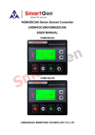
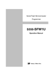
Manual Primozone® GM48 Ozone Generator 2 MANUAL © Primozone Production 2013 Primozone® Manual GM48 Series Ozone Generators_RevA_20130808.indd Primozone® MANUAL 3 Responsibility and Disclaimer Primozone accepts responsibility for the reliability and performance of this equipment only: • If any modifications to the equipment are authorized in writing by Primozone and carried out by an authorized service technician. • If the electrical installation for powering the equipment complies with all applicable local electrical codes and requirements including, if applicable, IEC requirements. • If the equipment is used in accordance with its manuals. Primozone will provide on request, a service manual which contains all necessary circuit diagrams and service information to enable authorized service technicians to repair those parts of this equipment which Primozone considers to be repairable. Since Primozone has no control over service work which is not performed by authorized service technicians, Primozone will in no way be responsible or liable for any damages resulting from the operation or performance of any device, or any injury caused thereby, after repair has been performed by any person other than a factory representative of Primozone. Under no circumstances will Primozone be liable for any indirect, incidental, special or consequential damages of any kind, its liability being hereby limited solely to repair or replacement. Note: Check your local regulations for any restrictions on ozone generators, power connections/regulation etc. Primozone Production AB Terminalvägen 2 246 42 Löddeköpinge, Sweden Tel +46 46 704570 Tel +46 734 433454 Fax: +46 46 704580 [email protected] www.primozone.com Manual GM48 Series Ozone Generators_RevA_20130808.indd © Primozone Production 2013 4 MANUAL Primozone® TABLE OF CONTENTS 1INTRODUCTION......................................................................6 1.1 The Primozone GM48..................................................................................... 6 1.2 Basic construction of the GM48 ozone generator............................................. 7 2 SAFETY PRECAUTIONS...........................................................8 2.1 Warning signs in the manual........................................................................... 8 2.2Personnel........................................................................................................ 9 2.3 Emergency stop.............................................................................................. 9 2.4Electricity...................................................................................................... 10 2.5Oxygen.......................................................................................................... 10 2.6Ozone........................................................................................................... 11 3INSTALLATION......................................................................12 3.1 Mechanical installation.................................................................................. 12 3.2 Electrical installation...................................................................................... 15 4OPERATIONS........................................................................16 4.1 Before first start-up....................................................................................... 16 4.2Condensation................................................................................................ 17 4.3 Module controller overview............................................................................ 18 4.4 Start-up after installation - flush and dry for 90 min....................................... 19 4.5 Normal operations......................................................................................... 20 APPENDIX A: TECHNICAL SPECIFICATIONS...............................23 A.1Dimensions................................................................................................... 23 A.2 Electrical data............................................................................................... 23 A.3 Oxygen gas supply........................................................................................ 23 A.4 Ozone gas..................................................................................................... 23 A.5 Cooling water................................................................................................ 23 A.6Noise............................................................................................................ 24 A.7 Control signal................................................................................................ 24 A.8Approval....................................................................................................... 24 A.9Disposal........................................................................................................ 24 A.10 Air................................................................................................................ 24 A.11 Electromagnetic compatibility........................................................................ 24 © Primozone Production 2013 Manual GM48 Series Ozone Generators_RevA_20130808.indd Primozone® MANUAL 5 APPENDIX B: HANDLING AND TRANSPORT...............................25 APPENDIX C: OZONE MATERIAL SAFETY DATA...........................26 APPENDIX D: INSPECTION........................................................27 APPENDIX E: ALARM SIGNALS AND TROUBLE SHOOTING.........29 APPENDIX F: SPARE PARTS LIST AND SEPT REPLACEMENT......31 F.1.1 Changing a SEPT.......................................................................................... 31 F.1.2 Removing a SEPT.......................................................................................... 32 F.1.3 Installing a SEPT........................................................................................... 34 Manual GM48 Series Ozone Generators_RevA_20130808.indd © Primozone Production 2013 6 Primozone® MANUAL 1 INTRODUCTION This manual describes the installation and operation process for the Primozone GM48 ozone generator. All personnel should read the whole manual before installing or operating the ozone generator. It is especially important that all personnel read and understand the “Safety precautions” chapter before handling the generator. Only trained personnel should be allowed to handle the ozone generator. Training is supplied by Primozone For more information, please contact Primozone at [email protected] or telephone +46 (0)46 70 45 70. 1.1 The Primozone GM48 This manual covers one of the ozone generator models in the Primozone GM-series; GM48 The ozone output can be set to between 10% and 100% of the maximum capacity at a given concentration of the ozone generators. The maximum capacity of the GM48 is according to the table below. Concentration 150 g/Nm3 200 g/Nm3 250 g/Nm3 300 g/Nm3 Max O3 capacity 2700 g/h 2400 g/h 1900 g/h 1300 g/h © Primozone Production 2013 Manual GM48 Series Ozone Generators_RevA_20130808.indd Primozone® MANUAL 7 1.2 Basic construction of the GM48 ozone generator 1. The reactors are installed in groups, called generator blocks, with six reactors per block. 2. Each generator block has an electrical power unit, a Self-regulating Electrical Power Transformer (SEPT). General: The SEPT is mounted on top of the generator block. The ozone generator consist of generator blocks with a corresponding SEPT. Figure 1: The GM48 without its cover Manual GM48 Series Ozone Generators_RevA_20130808.indd © Primozone Production 2013 8 MANUAL Primozone® 2 SAFETY PRECAUTIONS All personnel must read and understand the safety precautions before installing or operating the ozone generator. NOTE: In addition to the instructions and guidelines in this manual, make sure to follow all local safety regulations. 2.1 Warning signs in the manual This manual contains different messages; WARNINGS, CAUTIONS, RECOMMENDED ACTIONS and NOTES WARNING (heading in red) It is mandatory to follow the instructions of a warning message. Failure to do so can cause severe harm or death to personnel. CAUTION (heading in black) It is mandatory to follow the instructions of a caution message. Failure to do so can cause harm to personnel or severe damage to equipment. Warnings and cautions are marked with yellow warning triangles, with different meanings. WARNING General WARNING Fire hazard WARNING Toxic gas WARNING High voltage © Primozone Production 2013 Manual GM48 Series Ozone Generators_RevA_20130808.indd Primozone® MANUAL 9 In addition to the warning signs, there are RECOMMENDED ACTIONS and NOTES. RECOMMENDED ACTIONS Necessary security and preventive actions are marked with a blue mandatory sign. NOTE: A note is marked “Note:” and contains extra information that is useful when handling the ozone generator. 2.2 Personnel All personnel, working with the ozone generator, must use appropriate safety clothing and equipment, in accordance with company policy and relevant local regulations. NOTE: All personnel, operating the ozone generator, must be trained by authorized Primozone personnel. 2.3 Emergency stop It is highly recommended that the ozone generator is equipped with an emergency stop. NOTE: The emergency stop must be installed according to local regulation. Please check before installing. Before you reset the emergency stop, make sure that the reason for the stop has been eliminated. The emergency stop should only be used if there is risk for harm to personnel or damage to the equipment. DO NOT USE THE EMERGENCY STOP FOR NORMAL SHUT DOWN OF THE OZONE GENERATOR. 3x400V + N + PE Power supply Emergency stop circuit Lockable main power switch 3-phase power connector Power outlet GM18 Figure 2: Recommended installation of the emergency stop and power switch. FOLLOW LOCAL REGULATIONS. Manual GM48 Series Ozone Generators_RevA_20130808.indd © Primozone Production 2013 10 Primozone® MANUAL 2.4 Electricity The ozone generator has an input voltage of 3 x 400 V, which can be lethal. Do not remove the covers from a ozone generator unless the main power has been switched off. Do not remove the covers of the GM-series ozone generators, if not trained by Primozone personnel and have a written authorization. HIGH VOLTAGE Do not touch any inner electrical parts of the ozone generator. Physical contact with electrical parts can cause severe harm or death. If an accident occurs, immediately call for medical assistance. LOCK THE MAIN POWER SWITCH The lockable main power switch must be locked in the OFF position before any work on the electrical components is started. The main power switch is located near the ozone generator. Work on electrical equipment must be performed by authorized personnel only. Install using C-characteristic fuses on the incoming power supply. 2.5 Oxygen Oxygen is a colorless, odorless and tasteless gas. If there is a leakage of oxygen from the ozone generator, the oxygen content in the air is increased. Pure oxygen can cause oil and grease to spontaneously combust. FIRE HAZARD Do not smoke or light an open flame near the ozone generator. Make sure that you do not leave spill from oil or grease near the ozone generator. Figure 3, schematic picture of oxygen molecules © Primozone Production 2013 Manual GM48 Series Ozone Generators_RevA_20130808.indd Primozone® MANUAL 11 2.6 Ozone Ozone (O3) is a pale blue gas with a characteristic odor. It is highly reactive and corrosive and can cause harm if inhaled. TOXIC GAS Ozone is a toxic gas. Do not inhale ozone. Install an ozone alarm near the ozone generator. Ensure good ventilation. In case of accident, evacuate the person into fresh air and call for medical assistance. The human nose can detect ozone at concentrations above 0.02 ppm. The maximum allowable ozone concentration in industrial working areas is 0.10 ppm according to EU regulations, with a permissible human exposure of 8 hours per day, 6 days per week. Make sure that there is a functional ozone alarm in the room where the ozone generator is installed. The ozone sensor must be located within 2 meters from the ozone generator. Make sure that applicable safety equipment is available. NOTE: Make sure to follow applicable local regulations! For more hazard identification on ozone see Appendix C Ozone material safety data. Figure 4, schematic picture of ozone molecules Manual GM48 Series Ozone Generators_RevA_20130808.indd © Primozone Production 2013 12 MANUAL Primozone® 3 INSTALLATION This chapter goes through the installation of the GM48 generator 3.1 Mechanical installation Hoses for gas and cooling water, as well as bolts and O-rings for installing the hoses, are not supplied with the ozone generator. Position and install the ozone generator 1. Use a fork lift to move the ozone generator to where it is to be installed. Make sure that the fork is placed under the bottom stand of the ozone generator and that it is stabilized with straps while it is moved. 2. Place the ozone generator where it is to be installed in its upright and vertical position. Make sure that the location has a flat surface and that it is stable. 3. Make sure to have a distance of 0.7 meter behind the ozone generator to assure possible service. 4. Remove the transport protection. 5. Secure the ozone generator to the floor with four 12 mm bolts. The bolts are not supplied with the ozone generator. © Primozone Production 2013 Manual GM48 Series Ozone Generators_RevA_20130808.indd Primozone® MANUAL 13 3.1.1Install the hose for oxygen gas NOTE: Hoses are not supplied with the generator. Contact Primozone for a quote. NOTE! Before installation: • To secure oxygen purity make sure to connect a filter to the hose or make sure that the PSA/VSA/oxygen source is fitted with a filter. Filter requirement 0.01 micron. • The pressure regulator should be place after the filter and before the ozone generator. Ozone Oxygen source Filter 0,01 micron Pressure regulator GM ozone generator Figure 5 shows the pre-filtering precautions needed prior to installing the oxygen source to the ozone generator. Blow oxygen through the hose before connecting it to the ozone generator to make sure the hose is clean, dry and free from particles. 1. Connect the hose for inlet oxygen gas to the oxygen gas sorce. Make sure that the gas hose connector is securely fastened to the oxygen source. 2. Rinse the oxygen supply hose to make sure that no residual particles are left, which could propagate to the ozone generator and destroy it. 3. Remove the seals from the oxygen gas inlet at the rear of the ozone generator. 4. Connect the hose to the oxygen inlet. 3.1.2Install the hose for ozone gas NOTE: Hoses are not supplied with the generator. Contact Primozone for a quote. 1. Connect the hose for outlet ozone gas to the ozone system. Make sure that the ozone gas hose connector is securely fastened. 2. Remove the seal from the ozone gas outlet at the rear of the ozone generator. 3. Connect the hose to the ozone gas outlet. Manual GM48 Series Ozone Generators_RevA_20130808.indd © Primozone Production 2013 14 MANUAL Primozone® 3.1.3Install the hose for inlet cooling water NOTE: Hoses are not supplied with the generator. Contact Primozone for a quote. 1. Connect the hose for inlet cooling water to the water supply and connect the hose for outlet cooling water to the water drain/circulation connector. 2. Remove the seal at the water inlet and outlet connectors at the back of the ozone generator. 3. Connect the inlet water hose to the inlet water connector and the outlet water hose to the outlet water connector. COOLING WATER QUALITY AND TEMPERATURE The cooling water quality and temperature is very important for the performance of the ozone generator. Target temperature: +10°C Quality: drinking water quality, i.e. particle free and demineralized water or closed loop For more cooling water requirements refer to Appendix A.5. © Primozone Production 2013 Manual GM48 Series Ozone Generators_RevA_20130808.indd Primozone® MANUAL 15 3.2 Electrical installation All electrical installation must be done by authorized personnel and according to local regulations. ELECTRICITY The input voltage to the ozone generator is 400 V/230 V and physical contact with electrical parts can cause severe harm or death. If an accident occurs, immediately call for medical assistance. For more electrical requirements, refer to Appendix A.2 Install using C-characteristic fuses on the incoming power supply. 3.2.1Automatic fuses The ozone generator has 9 automatic fuses, which are located in the fuse box. The eight fuses on the left (F1 ... F8) are connected to each of the eight separate SEPTs. These are 20A fuses. The fuse to the far right (F9) is connected to the module controller of the ozone generator. This is a 2A fuse. NOTE: All fuses must be in the OFF position when the main power cable of the ozone generator is installed in the power outlet. 3.2.2Network cable The network cable must have an RJ45 plug to fit the ozone generator network connector. To install the network cable, insert the network cable plug into the network cable connector, at the bottom of the control cabinet. NOTE: The network cable is not supplied with the ozone generator. Manual GM48 Series Ozone Generators_RevA_20130808.indd © Primozone Production 2013 16 MANUAL Primozone® 4 OPERATIONS 4.1 Before first start-up Before you start the ozone generator for the first time, make sure that the following preparations have been performed: Make sure that all parts of the ozone production system are installed correctly. Make sure that the ozone alarm is functional in the room where the ozone generator is installed. The ozone sensor must be located within 2 meters from the ozone generator. The ozone generator must be in its upright position and securely fastened to the floor. The inlet hose for oxygen gas must be securely connected to the oxygen supply system Make sure to install a particle filter between the oxygen source and the ozone generator Make sure to flush the oxygen hose prior to connecting it to the ozone generator to make sure it is clean and dry. The outlet hose for ozone gas must be securely connected to the ozone system. The hoses for inlet and outlet cooling water must be securely connected to the cooling water system. Make sure that the nine automatic fuses in the ozone generator fuse box are in the OFF position. Make sure that the electrical wall plug of the ozone generator is securely installed in the power outlet. Make sure that the lockable main power switch is in the ON position. Make sure that the pressure, the temperature and the water flow of the cooling water is correct. See section A5 in Appendix A. Open the shut-off valves for inlet and outlet cooling water. Make sure that the oxygen gas pressure is correct. See section A3 in Appendix A. Open the shut-off valves for the oxygen gas supply and for the ozone gas outlet. The inlet for oxygen gas must have a pressure regulator (0-4 bar) and a visible gauge. © Primozone Production 2013 Manual GM48 Series Ozone Generators_RevA_20130808.indd Primozone® MANUAL 17 4.1.1Environmental requirements The ozone generator must be operated in an environment that meets the following criteria: Air humidity: Maximum 40% Air temperature: Minimum 5°C Air temperature: Maximum 40°C Air quality: The air must be free of dust, salt particles and conductive materials (like iron powder). Ozone alarm: There must be a functional ozone alarm in order to detect ozone leakage. The ozone sensor must be located within 2 meters from the ozone generator. Make sure that these criteria are not disregarded after the ozone generator has been installed and taken into use. 4.2 Condensation High ambient temperature in combination with low cooling water temperature may cause condensation inside the ozone generator. Even moderate condensation may cause system malfunction. To avoid this place the generator in dry or air-conditioned environment or connect it to a generator drier (adsorption drier). Primozone provides generator driers. Ask your local representative for a quotation. Manual GM48 Series Ozone Generators_RevA_20130808.indd © Primozone Production 2013 18 MANUAL Primozone® 4.3 Module controller overview 4.3.1Module controller screen overview Figure 6, schematic overview of the HMI on the Primozone GM48 4.3.2Module controller screen overview The GM48 HMI is constructed according to above. The system is based on a navigation bar (left hand side), where the ON/OFF, HOME, INFORMATION, SERVICE navigation buttons are available. In the top right hand side corner, there is the ALARM HISTORY and ACTIVE ALARM buttons available (assuming there are active alarms). Additionally, the operator can see the status of the different SEPTs on the main screen. These are in 3 different colors, according to below: • GREEN if the SEPT is functioning correctly and is turned ON • RED if the SEPT has triggered an alarm and is turned OFF • GRAY if the SEPT is turned OFF. If the unit is functioning correctly or is not available in this mode of operation. PRE-PURGING countdown is visible if the PRE-PURGING has been made available. This shows the total number of liters left of the purging (volume left prior to enabling ozone production). NOTE: Automatic PRE-PURGING is not supplied with the standard generator. Contact Primozone for a quote © Primozone Production 2013 Manual GM48 Series Ozone Generators_RevA_20130808.indd Primozone® MANUAL 19 4.4 Start-up after installation - flush and dry for 90 min When the ozone generator is started after installation or has been shut down for more than one week it needs to be flushed and dried before use. To flush and dry the ozone generator do the following. 1. Switch OFF the automatic fuses F1 ... F8. 2. Switch the automatic fuse F9 in the ozone generator fuse box to the ON position to start the ozone generator module controller. 3. Start the ozone generator by pressing ON/OFF button. Read the instruction and if applicable confirm the status of the generator, by pressing confirm. If not, attend to the generator to comply with the requirements prior to pressing confirm. NOTE: Since only fuse F9 is in the ON position, oxygen gas flows through the ozone generator but the ozone production has not started 4. Set the capacity to 100% via the touch panel. 5. Let the oxygen gas flow through the ozone outlet hose to dry the system. 6. After 90 minutes, stop the ozone generator by pressing ON/OFF button and the confirm Manual GM48 Series Ozone Generators_RevA_20130808.indd © Primozone Production 2013 20 MANUAL Primozone® 4.5 Normal operations NOTE: Make sure that all relevant automatic fuses are in the ON position. Make sure that the flow, the concentration and the pressure of the inlet oxygen gas are according to specification. See section A3 in Appendix A. Open the shut-off valves for oxygen, ozone and cooling water (if manual). 4.5.1Operation 1. Start the ozone generator by using the HMI. a. Press the ON/OFF button b. Read the instruction and if applicable confirm the status of the generator, by pressing confirm. c. If not, attend to the generator to comply with the requirements prior to pressing confirm. 2. Change the capacity/concentration a. Select the parameter that is going to be changed via the touch panel. b. Enter a new value c. Confirm the new value 3. Shutdown of the generator a. Press the ON/OFF button b. Confirm the shutdown NOTE: When the generator is shut off, it prior automatically purges for 3 minutes. If contact with the module controller is lost, use the lockable main power switch to shut down the ozone generator. In case of emergency, or if there is risk for harm to personnel or to the equipment, use the emergency stop to shut down the ozone generator. The emergency stop is located on the main power supply cable. Do not use the emergency stop for a normal stop of the ozone generator. © Primozone Production 2013 Manual GM48 Series Ozone Generators_RevA_20130808.indd Primozone® MANUAL 21 4.5.2Local or remote When one of the following add-ons have been purchased; • External signal • External control • External Modbus communication The LOCAL/REMOTE button will be available in the HMI. This button is shown in the illustration below. By pressing this button and confirming his/hers choice, the operator is able to change the system from LOCAL-mode to REMOTE and vice versa. Figure 7, Showing the LOCAL/REMOTE HMI on Primozone GM48 Manual GM48 Series Ozone Generators_RevA_20130808.indd © Primozone Production 2013 22 MANUAL Primozone® 4.5.3ODM The HMI is customized with an extra button, when the GM48 is accompanied by an ODM (Ozone Distribution Module). The ODM button is shown in the HMI, according to illustration below. Figure 8 showing the ODM HMI on Primozone GM48 Pressing the ODM button enables the operator to change screen to the ODM screen. In the ODM screen the operator is able to change the flow to individual lines. © Primozone Production 2013 Manual GM48 Series Ozone Generators_RevA_20130808.indd Primozone® MANUAL 23 APPENDIX A: TECHNICAL SPECIFICATIONS A.1 DIMENSIONS GM48 Weight: Height: Width (footprint): Depth (footprint): Sealing grade: 560 kg 1885 mm 830 mm 732 mm IP20 A.2 ELECTRICAL DATA Power supply: Power factor Power Control range Safety fuse 3x400 V + N + PE, AC 50/60 Hz 0.99 28 800 Watt (at 100 % capacity) 10-100 % Automatic fuse (8 units of 20 Ampere, 1 unit 2 Ampere) Install using C-characteristic fuses on the incoming power supply. A.3 OXYGEN GAS SUPPLY Gas pressure at inlet Gas flow range Oxygen purity Oxygen dew point Oxygen Connector 2.2 bar 0 - 350 nl/min (0° Celsius & 1 atm) 93-94 % is what the product is benchmarked with - 70° Celcius ½” internal threaded BSP A.4 OZONE GAS Ozone Pressure: Ozone Production: Ozone Connector 1,5 - 2,2 bar g (depending on the flow rate) 130 – 2700 grams per hour ½” internal threaded BSP A.5 COOLING WATER Water flow Temperature range Target temperature Water Connectors At least 5,33 m3/h +3° C to + 20° C 10° C 1 ½” internal threaded BSP Manual GM48 Series Ozone Generators_RevA_20130808.indd © Primozone Production 2013 24 MANUAL Primozone® A.6 NOISE Noise level: < 55 dB A.7 CONTROL SIGNAL Communication: Controller Modbus TCP PLC-based control system A.8 APPROVAL The Primozone ozone generators are CE-approved according to the Low Voltage Directive 2006/95/EU (EN60204-1:2006), and it is EMC certified according to EN610000-6-4:2007. A.9 DISPOSAL When the ozone generator is to be disposed of, all the electrical components and other materials must be taken care of in accordance to local regulations for electronic and industrial waste. The ozone generator does not contain any radiating or otherwise hazardous materials that require special destruction. Please make sure to follow local regulations when disposing the ozone generator and use possibilities to recycle materials that are recyclable. A.10 AIR Minimum air temperature: 5°C Maximum air temperature: 40°C The air must be free of dust, salt particles and conductive materials (like iron powder). A.11 ELECTROMAGNETIC COMPATIBILITY The ozone generators are EMC-approved according to international standard (EN 61000-64:2007). © Primozone Production 2013 Manual GM48 Series Ozone Generators_RevA_20130808.indd Primozone® MANUAL 25 APPENDIX B: HANDLING AND TRANSPORT When in transport, the ozone generator must be handled with care. Keep it vertical and make sure that it is kept dry and well protected from physical impact. Use a fork lift to move the ozone generator. Make sure that the fork is placed under the bottom stand and that the ozone generator is stabilized by straps. See figure B1. Do not move the ozone generator by lifting it by any of its parts. Make sure that the following precautions are taken into consideration when you move, handle or transport the ozone generator: • The electrical components of the ozone generator must not be exposed to water, oil or chemicals. • The ozone generator must not be exposed to temperatures higher than 55°C during handling or transportation. • Avoid rapid changes of the surrounding temperature as this can cause condensation inside the ozone generator, which can damage the electrical parts. • Drain all cooling water from the ozone generator before it is transported. Figure B1, When you use a fork lift to move the ozone generator, make sure that the fork is placed under the bottom stand. Do not lift the ozone generator by any of its parts Manual GM48 Series Ozone Generators_RevA_20130808.indd © Primozone Production 2013 26 MANUAL Primozone® APPENDIX C: OZONE MATERIAL SAFETY DATA An updated Ozone Material Data Sheet is to be found at www.primozone.com/datasheets © Primozone Production 2013 Manual GM48 Series Ozone Generators_RevA_20130808.indd Primozone® MANUAL 27 APPENDIX D: INSPECTION D.1 VISUAL INSPECTION In addition to the system control monitoring of the ozone generator, regular visual inspections must be performed to ensure that the ozone generator is running smoothly. This manual lists inspections for daily or weekly checks. For inspections that are performed less frequently, please refer to the ozone generator Maintenance manual. D.2 DAILY VISUAL INSPECTION Do a visual inspection of the ozone generator every day when it is in use. Check the following: • SEPT indicators Make sure that the indicator lamp in the front of each SEPT shows a steady green light. If one of the SEPTs has an orange indicator light, refer to Appendix B. • Automatic fuses Make sure that all nine automatic fuses in the fuse box are in the ON position. If any of the fuses is in the OFF position, call Primozone for support. • Condensation Examine the ozone generator for condensed water, especially around the connector for inlet cooling water. If there is excess condensation, make sure that the environment complies with the required conditions. Refer to the ozone generator Installation manual. • Sound Listen for noises from the ozone generator. If any unusual noises are heard, examine the ozone generator for leakage or contact Primozone Production AB. • Ozone production Make sure that the ozone production complies with the requested specification. Refer to the ozone generator Module Controller manual for instructions on how to read and set the ozone production parameters. Manual GM48 Series Ozone Generators_RevA_20130808.indd © Primozone Production 2013 28 MANUAL Primozone® D.3 WEEKLY VISUAL INSPECTION In addition to the daily inspection, a weekly check of the ozone generator must be performed. Check the following: • Environment Make sure that the temperature and the air humidity are within specifications in the room where the ozone generator is installed. Refer to section 4 for specifications. Refer to the ozone generator Module Controller manual for information on how to read and set the system parameters. • Oxygen gas Make sure that the gas regulator for the oxygen supply shows the specified value. Refer to section A3 in Appendix A. • Cooling water Make sure that there are no leaks from the cooling water connectors at the rear of the ozone generator. Make sure that the pressure, the temperature and the water flow of the cooling water are within specifications. Refer to A5 in Appendix A. © Primozone Production 2013 Manual GM48 Series Ozone Generators_RevA_20130808.indd Primozone® MANUAL 29 APPENDIX E: ALARM SIGNALS AND TROUBLE SHOOTING The table below lists the Primozone GM-series ozone generator’s alarm signals, probable cause for the alarm and recommended actions. Alarm signal/Problem Probable cause Recommended action 1 A SEPT alarm is triggered Error in the SEPT or a (shown in the module reactor controller). Contact Primozone Production AB. 2 The ozone generator will 1. Oxygen gas leakage not start - leak test failure 2. Water leakage 1. Check if any active alarms. 3. Other 2. Remedy the cause of the alarms. 3. Contact Primozone Production AB. 3 One of the fuses is in the OFF position 1. Short circuit Try resetting the fuse. 2. Faulty fuse Make sure that all external cables and connectors are intact and securely connected. Make sure that the incoming voltage supply has not decreased. Make sure that you have eliminated the cause for the automatic stop before you reset the automatic fuse. Manual GM48 Series Ozone Generators_RevA_20130808.indd © Primozone Production 2013 30 MANUAL 4 Primozone® Alarm signal/Problem Probable cause Recommended action Automatic shut-down of the ozone generator 1. Power failure 1. Make sure that all automatic fuses are in the ON position and that all cables are intact and connected. 2. Oxygen gas pressure too low or too high 3. Ozone leakage 4. Cooling water temp above 40°C 5. Cooling water pressure too low 6. Other 2. Make sure that the oxygen gas supply system works according to specification. 3. Ensure good ventilation. 4. Make sure the cooling system is ON. 5. Make sure there is no leakage in the system. 6. Contact Primozone Production AB. © Primozone Production 2013 Manual GM48 Series Ozone Generators_RevA_20130808.indd Primozone® MANUAL 31 APPENDIX F: SPARE PARTS LIST AND SEPT REPLACEMENT Spare parts that are available for the ozone generator are listed in the table below. Please contact Primozone Production for more information on the spare parts and instructions on how to install them on the ozone generator 1 Article SEPT Article number 100.027 F.1 CHANGING SPARE PARTS Normally, all maintenance work is done by Primozone Production AB. However after going through the Primozone service education, the changing of a SEPT can be performed by the owner of the GM ozone generator. HIGH VOLTAGE Do not touch any inner electrical parts of the ozone generator. Physical contact with electrical parts can cause severe harm or death. If an accident occurs, immediately call for medical assistance. LOCK THE MAIN POWER SWITCH The lockable main power switch must be locked in the OFF position before any work on the electrical components is started. F.1.1Changing a SEPT The GM48 has eight electrical power units, called SEPTs (Self-regulating Electronic Power Transformer). Indications that one or more SEPTs must be changed are, for example: • a power drop in the SEPT • decreased ozone outlet • an orange indicator light in the front of the SEPT Before you change a SEPT, make sure that a faulty SEPT is the source of the problem. Manual GM48 Series Ozone Generators_RevA_20130808.indd © Primozone Production 2013 32 Primozone® MANUAL F.1.2Removing a SEPT 1. Open the cable lock (2) on the SEPT power supply connector (1). According to figure below. WARNING Make sure that the lockable main power switch is locked in the OFF position before you start to remove the SEPT. 1 2 3 4 5 6 7 1. SEPT power supply connector 2. Lock on the SEPT power supply connector 3.SEPT 4. Lock on the network cable connector 5. Network cable connector 6. Bolts (4 pcs) 7. High voltage cable connector Figure F1, schematic overview part involved in removing the SEPT 2. Pull the SEPT power supply connector (1) straight out from the SEPT. CAUTION Do not pull at the cable to remove it, pull at the cable plug. 3. Open the cable lock (4) on the network cable connector (5). 4. Disconnect the network cable connector (5) from the SEPT. 5. Unscrew the high voltage cable connector (7) and pull it straight down to remove it from the SEPT. 6. Loosen the four bolts (5) from the front of the SEPT. Note: The SEPT is now free to be removed from the ozone generator. © Primozone Production 2013 Manual GM48 Series Ozone Generators_RevA_20130808.indd Primozone® MANUAL 33 7. Lift the front of the SEPT slightly, so that it does not touch the aluminum plate (6). 8. With the front slightly lifted, carefully push the SEPT toward the rear of the ozone generator, so that the steel list (7) under the SEPT is pushed out from the groove at the back of the aluminum plate (6). 9. Lift the SEPT up and then out from the ozone generator. 1 2 3 8 4 7 6 5 1.SEPT 2. Power cable socket 3. Ventilation holes 4. Allen key 5. Bolts (4 pcs) 6. Aluminum plate 7. Steel list 8. Contact areas Figure F2, showing the SEPT from the side accommodated with instructions. Manual GM48 Series Ozone Generators_RevA_20130808.indd © Primozone Production 2013 34 MANUAL Primozone® F.1.3Installing a SEPT Before you start to install the SEPT, make sure that the lockable main power switch is locked in the OFF position. HIGH VOLTAGE Do not touch any inner electrical parts of the ozone generator. Physical contact with electrical parts can cause severe harm or death. If an accident occurs, immediately call for medical assistance. LOCK THE MAIN POWER SWITCH The main power must be switched off and the main power switch must be locked in the OFF position before any work on the electrical components is started. CAUTION The aluminum plate and the bottom of the SEPT must be clean from dirt, dust and other particles. 1. Place the SEPT in the ozone generator: a. Hold the SEPT as high up as possible in the space where it is to be installed, and lift it into and toward the rear of the GM48. Avoid touching the aluminum plate (6) and make sure that no dirt falls into the greasing oil. b. Tilt the SEPT slightly and lower it carefully, so that the steel list (7) under the SEPT goes behind the aluminum plate. c. With the SEPT still slightly tilted, pull it toward you, so that the steel list (7) under the SEPT goes into the groove at the back of the aluminum plate. d. Carefully put the SEPT down on the aluminum plate while pulling it toward you. e. Make sure that the SEPT is firmly set and that there is no gap between the SEPT and the aluminum plate. 2. Tighten the four bolts (5) that hold the SEPT to the ozone generator. 3. Install the high voltage cable connector (7) in the SEPT. Refer to figure F1. 4. Turn the connector on the high voltage cable (7), so that the cable is securely fastened to the SEPT. 5. Install the network cable connector (5) in the SEPT and close the lock (4). 6. Install the SEPT power supply connector (1) in the SEPT and close the lock (2). NOTE: Make sure that all cables are securely fastened to the SEPT before installing the front cover on the zone generator. 7. Install the steel front cover on the ozone generator. © Primozone Production 2013 Manual GM48 Series Ozone Generators_RevA_20130808.indd Primozone® MANUAL Manual GM48 Series Ozone Generators_RevA_20130808.indd 35 © Primozone Production 2013 About Primozone At Primozone® we are committed to provide our customers with cost efficient and environmentally friendly ways to clean and treat water with ozone. Our ozone generators and ozone water treatment systems are based on cutting-edge technology and generate far more ozone while using far less energy. At Primozone we have found an innovative way to make ozone generation efficient and cost effective. Our solution has proven to save up to 70% of the energy consumption compared to traditional ozone generators. Furthermore the Primozone Ozone Generator is small and has the capacity to generate ozone with a proven high concentration. Ozone is not only a natural product but also one of the most efficient methods to clean and treat water. Primozone Production AB Terminalvägen 2, 246 42 Löddeköpinge, Sweden Phone +46 46 70 45 70 Fax +46 46 70 45 80 Mail [email protected] www.primozone.se © Primozone Production AB 2013-2014. Primozone Production reserves the right to change any information in this publication without prior notice. Primozone Production does not take any responsibility for errors or omissions in this publication.