1
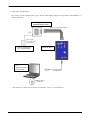
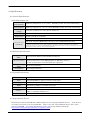
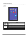
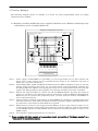
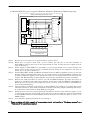
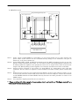
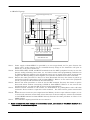
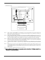
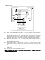
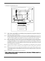
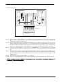
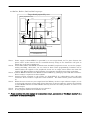
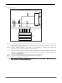
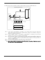
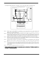
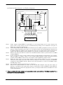
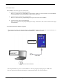
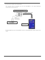
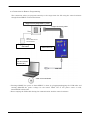
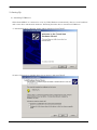
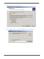
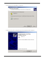
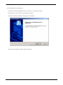
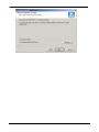
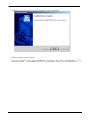
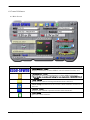
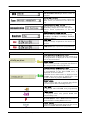
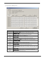
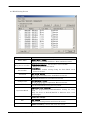
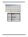
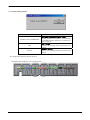
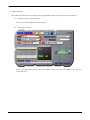
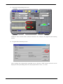
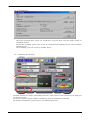
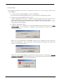
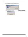
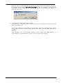
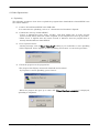
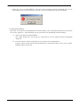
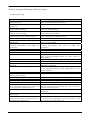
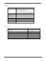
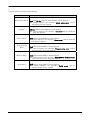
Serial Flash Microcomputer
Programmer
S550-SFW1U
Operation Manual
Sunny Giken Inc.
Serial Flash Microcomputer Programmer
S550-SFW1U
The contents of this manual may be revised without notice.
We, Sunny Giken Inc. shall not be responsible for any damages
and/or losses caused by using this product and/or the software attached
to this product claimed by users and/or any intermediaries.
Specifications of this product and/or the software attached to this
product may be modified without notice for improvement.
The names of systems, products, and/or services used in this manual
are either registered trademarks or trademarks of each manufacturer.
The captions of the TM and (R) are not mentioned in this manual.
S550-SFW1U, Serial Flash Programmer Operation Manual
1
Table of Contents
1. Outline .......................................................................................................................................................... 3
1.1 Precautions ............................................................................................................................................. 3
1.2 System Configuration ............................................................................................................................ 4
2. Specifications................................................................................................................................................ 5
2.1 General Specifications ........................................................................................................................... 5
2.2 Function Specifications.......................................................................................................................... 5
2.3 System Requirements ............................................................................................................................ 5
2.4 Programmable Device ............................................................................................................................ 5
2.5 S550-SFW1U External Appearance...................................................................................................... 6
2.6 Connector Pin Specifications for Serial Programming ........................................................................ 8
3. Circuitry Example........................................................................................................................................ 9
3.1 M16C/60 (excluding 62P[double power supplies]), M16C/80 series, M32C/83, M16C/24 groups and
R32C/100 series (excluding R32C/112) ....................................................................................................... 9
3.2 M16C/62P[double power supplies], M32C/84, M32C/85, M32C/86 and R32C/112 groups .............. 10
3.3 M16C/50 series ......................................................................................................................................11
3.4 M16C/1N group .................................................................................................................................... 12
3.5 M16C/22 group ..................................................................................................................................... 13
3.6 M16C/26 groups.................................................................................................................................... 14
3.7 M16C/28, and M16C/29 groups ........................................................................................................... 15
3.8 M16C/2N group .................................................................................................................................... 16
3.9 R8C/10, R8C/11, R8C/12, R8C/13 groups............................................................................................ 17
3.10 R8C/LX series ..................................................................................................................................... 18
3.11 R8C family other than R8C/10, R8C/11, R8C/12, R8C/13 groups and R8C/LX series ................... 19
3.12 Eight-bit Microcomputer, 740 Family - 7641, 7643, 38C2, 38K0, and 38K2 groups ..................... 20
3.13 Eight-bit Microcomputer, 740 Family 7542 group ........................................................................... 21
4. Connections ................................................................................................................................................ 22
4.1 Connection for Download / Upload...................................................................................................... 22
4.2 Connection for Stand-alone Programming ......................................................................................... 23
4.3 Connection for Remote Programming................................................................................................. 24
5. Setting Up................................................................................................................................................... 25
5.1 Installing USB driver........................................................................................................................... 25
5.2 Installing Control Software ................................................................................................................. 28
5.3 Uninstalling Control Software ............................................................................................................ 30
6. Control Software ........................................................................................................................................ 31
6.1 Main Screen.......................................................................................................................................... 31
6.2 Program Data Selecting Screen .......................................................................................................... 34
6.3 Loaded Program File Selecting Screen ............................................................................................... 35
6.4 Program Data Editing Screen ............................................................................................................. 36
6.5 Block Setting Screen ............................................................................................................................ 37
6.6 ID Setting Screen ................................................................................................................................. 38
6.7 Protect Setting Screen ......................................................................................................................... 39
6.8 Program Progress Status Screen ........................................................................................................ 39
6.9 S550-SFW1U Product Information ..................................................................................................... 40
7. Programming Operations .......................................................................................................................... 43
7.1 Process Flow up to Programming........................................................................................................ 43
7.2 Data Settings........................................................................................................................................ 44
7.3 Downloading ......................................................................................................................................... 47
7.4 Stand-alone Programming................................................................................................................... 49
7.5 Remote Programming .......................................................................................................................... 50
8. Other Operations ....................................................................................................................................... 52
8.1 Uploading.............................................................................................................................................. 52
8.2 Initializing Memory ............................................................................................................................. 53
9. Error messages, Warnings, Other messages ............................................................................................ 54
9.1 Message Dialog..................................................................................................................................... 54
9.2 LED Status List ................................................................................................................................... 55
9.3 Beep Sounds ......................................................................................................................................... 55
9.4 List of Errors during Programming .................................................................................................... 56
S550-SFW1U, Serial Flash Programmer Operation Manual
2
1. Outline
1.1 Precautions
Thank you for purchasing our product S550-SFW1U, the Serial Flash Microcomputer Programmer.
Please read this operation manual carefully to understand the functions of this product for effective
and stable operations. Please beware that Sunny Giken Inc. shall have no liability for any damages
and/or troubles caused by misuse or careless handling of this product.
1) General Cautions
Please observe the following points to avoid hazards such as fire, burns, electric shock, and/or
injures:
- Use this product under proper environment.
- Never use this product placed up side down or vertically.
- Handle this product with care to avoid high impact caused by fall and/or physical shock.
- Never disassemble and/or modify this product by yourself.
2) Operating Environment
- Do not use this product in environments described below:
Dusty places
Places where there is the presence of corrosive gases
Places exposed to direct sunlight
Places surrounded by equipments that could become sources of noises
Places with severe mechanical shock and/or constant mechanical vibration
- Operational ambient temperature 0°C to 40°C
Humidity: below 80% (non condensing)
- Preventing electrostatic buildup for handling this product and devices is highly
recommended.
3) Storage
- If you do not plan to use this product for a long time, put this product in the packing box in
which the product had been delivered, and store it in the shade with the ambient
temperature of -10°C to +40°C and below 80% of humidity (non condensing).
4) Transportation
- When transporting this product, be sure to use the packing box in which the product had
been delivered when you made your purchase.
5) Cleaning
- Wipe the product with soft and clean fabric when it needs cleaning. Never use any sort of
organic solvent such as benzine that may cause this product to deteriorate.
S550-SFW1U, Serial Flash Programmer Operation Manual
3
1.2 System Configuration
The entire system configuration of the Serial Flash Microcomputer Programmer S550-SFW1U is
illustrated below.
Target board
prepared by the user
Target Connecting Cable
Vcc
Use it with
V cc=3.3V ±5%
or 5V ±5%
Power supply for
the target board
S550-SFW1U
PC
(OS:Windows98,
Me,2000,XP )
USB Cable
SFW Control
Software
* For details on connection according to functions, refer to “4. Connections”.
S550-SFW1U, Serial Flash Programmer Operation Manual
4
2. Specifications
2.1 General Specifications
S550-SFW1U Main unit
Operating
Ambient temperature : 0°C to 40°C Humidity: below 80% (non-condensing)
Environment
Storage
Ambient temperature: -10°C to +40°C Humidity: below 80% (non-condensing)
Environment
Operating
3.3V plus or minus 5%, or 5V plus or minus 5%
voltage
Power capacity Equal to DC5V 80mA or lower
Dimensions
Weight
55 (W) x 85 (H) x 17 (D) mm
Approximately 60g
CE mark obtained (MI:EN55011 Group1 ClassA ,EMS:EN610000-6-2)
International
standards
FCC compliance
This device complies with part 15 of the FCC Rules. Operation is subject to the following two conditions;
(1) This device may not cause harmful interference, and (2) this device must accept any interference received,
including interference that may cause undesired operation.
2.2 Function Specifications
Programmable
MCU
Operation Mode
Programming
Mode
Action Mode
Renesas Flash Memory Internal Microcomputer
Standard serial I/O mode (clock synchronous serial I/O and single wire
clock asynchronous serial I/O(applicable to R8C/Tiny series ))
* Clock asynchronous serial I/O mode not supported.
Serial Programming
Erase/Program/Verify
2.3 System Requirements
Host Machine
CPU
Memory
IBM PC/AT Compatible machine
Pentium200MHz or higher processor clock speed
64Mbyte or higher
HDD
Minimum of 10Mbyte available disk space
CRT
800 x 600 dots or better, minimum of 16 bits (24 bits or more recommended)
CD-ROM drive x 1
USB 1.1 compliant USB port x 1
Microsoft Windows98, Me, 2000, XP
Others
OS
2.4 Programmable Device
The Renesas built-in Flash Memory Microcomputers are the programmable devices. Some devices
are under evaluation or not programmable. Refer to the file “Programmable device List” in the
enclosed CD-ROM. For latest information, please visit Sunny Giken’s homepage:
http://www.sunnygiken.jp/english/sfw1u-support-e.html
S550-SFW1U, Serial Flash Programmer Operation Manual
5
2.5 S550-SFW1U External Appearance
The external appearance of S550-SFW1U is shown below with descriptions of switches, LEDs and
connectors.
* Front View
Switch/LED
Power LED
USB LED
POWER
USB
PASS
Programming
result LEDs
ID ERR
FAIL
Start Switch
Function
Is lighted when the power is supplied to S550-SFW1U
(including when the power is supplied from the target bard).
Is lighted when the PC and S550-SFW1U is connected through
USB, and blinks while accessing.
Is lighted when programming to the target is completed
successfully.
Is lighted when “ID Error” occurs while programming to the
target.
Is lighted when errors other than ID error occurs while
programming to the target.
Starts programming to the target.
S550-SFW1U, Serial Flash Programmer Operation Manual
6
* Top Side View
Connector
Serial
Function
Cable connector (connecting to the target)
* Bottom Side View
Connector
USB
Function
USB (mini B) Communication connector (connecting to PC).
S550-SFW1U, Serial Flash Programmer Operation Manual
7
2.6 Connector Pin Specifications for Serial Programming
- Connector Pin(S550-SFW1U Main unit)
Model :HIF3FC-10PA-2.54DS Hirose Electric
- Pin Assignment (S550-SFW1U Unit)
*Note that signal names and directions are ones seen from the programmer side.
Especially, 4:TXD and 10:RXD would be the other way around when seen from the target side.
Pin No.
Signal Name
Descriptions
Direction
1
Vcc
Power is supplied to S550-SFW1U through Vcc
pins when programming.
-
2
BUSY
3
CLK
Clock signal output for serial programming
4
TXD
Transmission data for serial programming
Output
Output
5
CE
CE signal output for serial programming
Output
6
EPM
EPM signal output for serial programming
Output
7
GND
Signal ground
8
RESET
RESET signal output for serial programming
Output
9
CNVss
CNVss (Vpp) signal output for serial programming
Output
10
RXD
Busy signal input for serial programming
Received data for serial programming
Pin No.9
Input
Input
Pin No.1
Pin No.10
Pin No.2
- Target Connecting Cable
The attached cable for connecting a target is a straight cable. If the connector on the cable does
not match the one on the target board, cut off one side and attach a matching connector
referencing the above pin assignment. Be sure to arrange the cable carefully so that the length
of the target connecting cable would be 500mm or less.
Pin NO.1
500mm
Connector Model: HIF3BA-10D-2.54R, Hirose Electric
S550-SFW1U, Serial Flash Programmer Operation Manual
8
3. Circuitry Example
The following diagram shows an example of a circuit for serial programming when you design
peripheral circuit of MCU.
3.1 M16C/60 (excluding 62P[double power supplies]), M16C/80 series, M32C/83, M16C/24 groups
and R32C/100 series (excluding R32C/112)
Target board prepared by user
Peripheral circuit of MCU
MCU
TXD
RXD
SCLK
BUSY
Vcc
Note 2
Note 3
Reset circuit
Note 6
Note 4
CE
EPM
CNVss
Pull up
or
Pull down
Note 5
RESET Vss
Note 1
1 2 3 4 5
6 7 8 9 10
Serial Cable
Vcc
CLK
CE*
GND CNVss
BUSY TXD EPM* RESET* RXD
S550-SFW1U Unit
Note 1. Power supply of S550-SFW1U is provided by a user target board via Vcc pins. Connect the
power source of the board to the Vcc terminal directly. Usage of Vcc should be 3.3V plus or
minus 3%, or 5V plus or minus 3%.
Note 2. Isolate TXD, RXD, SCLK, and BUSY terminals from the MCU peripheral circuit, in case the
jumper, analog switching, three-state, etc. are built in when serial programming. Isolation can
be omitted when the signals to the peripheral circuit are in output status when seen from the
target CPU. When pulling-up these signals, the resistance should be more than 4.7k ohms.
Note 3. Execute the same procedure as “Note 2” for CE and EPM terminals. You may also choose to
pull-up or pull-down each and isolate without connecting to CE and EPM on S550-SFW1U.
When they are not used in the peripheral circuit, you may fix CE at H level and EPM at L
level on the board directly.
Note 4. Connect CNVss terminal to the CNVss on S550-SFW1U by pulling-up or pulling-down with
10K ohm resistance. If the CNVss terminal is fixed at H level by jumper switching and others,
no connection to the CNVss on S550-SFW1U is required.
Note 5. When the reset circuit on your target board is CR delay circuit or open collector output, or it is
a circuit with constant current load of less than tens of micron amperes, connect the terminal
to the RESET terminal on S550-SFW1U directly. Execute the same procedure as “Note 2” for
CMOS output.
Note 6. Vss terminal is signal ground. Be sure to connect it.
* Please combine with this example of a connection circuit, and confirm a "Hardware manual" or a
"Data sheet" of each microcomputer.
S550-SFW1U, Serial Flash Programmer Operation Manual
9
3.2 M16C/62P[double power supplies], M32C/84, M32C/85, M32C/86 and R32C/112 groups
Target board prepared by user
Peripheral circuit of MCU
MCU
Note 2
TXD Vcc
RXD
Note 1
SCLK
BUSY Vcc
Note 4
Note 5
Reset circuit
Note 8
Note 6
CE
EPM
CNVss
Pull up
or
Pull down
Note 7
RESET Vss
Note 3
1 2 3 4 5 6 7 8 9 10
Serial Cable
Vcc
CLK
CE
GND CNVs
BUSY TXD EPM RESET RXD
S550-SFW1U Unit
Note 1. Be sure to set it so that Vcc1 is greater than or equal to Vcc2.
Note 2. When Vcc1 is greater than Vcc2, do not connect the CE pin to the CE terminal on
S550-SFW1U. Please pull it up on the target board by Vcc2. In case that Vcc1 equals to Vcc2,
refer to the Note 5.
Note 3. Power supply of S550-SFW1U is provided by a user target board via Vcc pins. Connect the
power source of the board to the Vcc terminal directly. Usage of Vcc should be 3.3V plus or
minus 3%, or 5V plus or minus 3%.
Note 4. Isolate TXD, RXD, SCLK, and BUSY terminals from the MCU peripheral circuit, in case the
jumper, analog switching, three-state, etc. are built in when serial programming. Isolation can
be omitted when the signals to the peripheral circuit are in output status when seen from the
target CPU. When pulling-up these signals, the resistance should be more than 4.7k ohms.
Note 5. Execute the same procedure as “Note 4” for CE and EPM terminals. You may also choose to
pull-up or pull-down each and isolate without connecting to CE and EPM on S550-SFW1U.
When they are not used in the peripheral circuit, you may fix CE at H level and EPM at L
level on the board directly.
Note 6. Connect CNVss terminal to the CNVss on S550-SFW1U by pulling-up or pulling-down with
10K ohm resistance. If the CNVss terminal is fixed at H level by jumper switching and others,
no connection to the CNVss on S550-SFW1U is required.
Note 7. When the reset circuit on your target board is CR delay circuit or open collector output, or it is
a circuit with constant current load of less than tens of micron amperes, connect the terminal
to the RESET terminal on S550-SFW1U directly. Execute the same procedure as “Note 4” for
CMOS output.
Note 8. Vss terminal is signal ground. Be sure to connect it.
* Please combine with this example of a connection circuit, and confirm a "Hardware manual" or a
"Data sheet" of each microcomputer.
S550-SFW1U, Serial Flash Programmer Operation Manual
10
3.3 M16C/50 series
Target board prepared by user
MCU peripheral circuit
MCU
Note2
TXD
Vcc
RXD
SCLK
BUSY
Reset circuit
Note5
Note3
Note4
CNVss
RESET Vss
Note1
1 2 3 4 5 6 7 8 9 10
Serial cable
CLK
CE
GND CNVss
Vcc
BUSY TXD EPM RESET
RXD
S550-SFW1U unit
Note 1. Power supply of S550-SFW1U is provided by a user target board via Vcc pins. Connect the
power source of the board to the Vcc terminal directly. Usage of Vcc should be 3.3V plus or
minus 3%, or 5V plus or minus 3%.
Note 2. Isolate TXD, RXD, SCLK, and BUSY terminals from the MCU peripheral circuit, in case the
jumper, analog switching, three-state, etc. are built in when serial programming. Isolation can
be omitted when the signals to the peripheral circuit are in output status when seen from the
target CPU. When pulling-up these signals, the resistance should be more than 4.7k ohms.
Note 3. Connect CNVss terminal to the CNVss on S550-SFW1U by pulling-down with 10K ohm
resistance. Do not connect a capacitor to this terminal. For other circuits, please consult with
us.
Note 4. When the reset circuit on your target board is CR delay circuit or open collector output, or it is
a circuit with constant current load of less than tens of micron amperes, connect the terminal
to the RESET terminal on S550-SFW1U directly. Execute the same procedure as “Note 2” for
CMOS output.
Note 5. Vss terminal is signal ground. Be sure to connect it.
* Please combine with this example of a connection circuit, and confirm a "Hardware manual" or a
"Data sheet" of each microcomputer.
S550-SFW1U, Serial Flash Programmer Operation Manual
11
3.4 M16C/1N group
Target board prepared by user
MCU peripheral circuit
MCU
Note2
TXD
Vcc
RXD
SCLK
BUSY
Note3
CE
SEL
Note4
Reset circuit
Note7
Note5
Note6
CNVss
RESET Vss
Note1
1 2 3 4 5 6 7 8 9 10
Serial cable
Vcc
CLK
CE
GND CNVss
BUSY TXD EPM RESET
RXD
S550-SFW1U unit
Note 1. Power supply of S550-SFW1U is provided by a user target board via Vcc pins. Connect the
power source of the board to the Vcc terminal directly. Usage of Vcc should be 3.3V plus or
minus 3%, or 5V plus or minus 3%.
Note 2. Isolate TXD, RXD, SCLK, and BUSY terminals from the MCU peripheral circuit, in case the
jumper, analog switching, three-state, etc. are built in when serial programming. Isolation can
be omitted when the signals to the peripheral circuit are in output status when seen from the
target CPU. When pulling-up these signals, the resistance should be more than 4.7k ohms.
Note 3. Execute the same procedure as “Note 2” for the CE terminal. You may also choose to pull it up
and isolate without connecting to CE on S550-SFW1U. When it is not used in the peripheral
circuit, you may fix CE at H level on the board directly.
Note 4. Execute the same procedure as “Note 2” for the SEL terminal. You may also choose to pull it
down and isolate without connecting to EPM on S550-SFW1U. When it is not used in the
peripheral circuit, you may fix SEL at L level on the board directly.
Note 5. Connect CNVss terminal to the CNVss on S550-SFW1U by pulling-down with 10K ohm
resistance. Do not connect a capacitor to this terminal. For other circuits, please consult with
us.
Note 6. When the reset circuit on your target board is CR delay circuit or open collector output, or it is
a circuit with constant current load of less than tens of micron amperes, connect the terminal
to the RESET terminal on S550-SFW1U directly. Execute the same procedure as “Note 2” for
CMOS output.
Note 7. Vss terminal is signal ground. Be sure to connect it.
* Please combine with this example of a connection circuit, and confirm a "Hardware manual" or a
"Data sheet" of each microcomputer.
S550-SFW1U, Serial Flash Programmer Operation Manual
12
3.5 M16C/22 group
Target board prepared by user
MCU peripheral circuit
MCU
Note2
TXD
Vcc
RXD
SCLK
BUSY
Note3
CE
Note4
CNVss
Reset circuit
Note6
Note5
RESET Vss
Note1
1 2 3 4 5 6 7 8 9 10
Serial cable
Vcc
CLK
CE
GND CNVss
BUSY TXD EPM RESET
RXD
S550-SFW1U unit
Note 1. Power supply of S550-SFW1U is provided by a user target board via Vcc pins. Connect the
power source of the board to the Vcc terminal directly. Usage of Vcc should be 3.3V plus or
minus 3%, or 5V plus or minus 3%.
Note 2. Isolate TXD, RXD, SCLK, and BUSY terminals from the MCU peripheral circuit, in case the
jumper, analog switching, three-state, etc. are built in when serial programming. Isolation can
be omitted when the signals to the peripheral circuit are in output status when seen from the
target CPU. When pulling-up these signals, the resistance should be more than 4.7k ohms.
Note 3. Execute the same procedure as “Note 2” for the CE terminal. You may also choose to pull it up
and isolate without connecting to CE on S550-SFW1U. When it is not used in the peripheral
circuit, you may fix CE at H level on the board directly.
Note 4. Connect CNVss terminal to the CNVss on S550-SFW1U by pulling-down with 10K ohm
resistance. Do not connect a capacitor to this terminal. For other circuits, please consult with
us.
Note 5. When the reset circuit on your target board is CR delay circuit or open collector output, or it is
a circuit with constant current load of less than tens of micron amperes, connect the terminal
to the RESET terminal on S550-SFW1U directly. Execute the same procedure as “Note 2” for
CMOS output.
Note 6. Vss terminal is signal ground. Be sure to connect it.
* Please combine with this example of a connection circuit, and confirm a "Hardware manual" or a
"Data sheet" of each microcomputer.
S550-SFW1U, Serial Flash Programmer Operation Manual
13
3.6 M16C/26 groups
Target board prepared by user
MCU peripheral circuit
MCU
Note2
TXD
Vcc
RXD
SCLK
BUSY
CE
Note3
RP
Reset circuit
Note6
Note4
Note5
CNVss
RESET Vss
Note1
1 2 3 4 5 6 7 8 9 10
Serial cable
Vcc
CLK
CE
GND CNVss
BUSY TXD EPM RESET
RXD
S550-SFW1U unit
Note 1. Power supply of S550-SFW1U is provided by a user target board via Vcc pins. Connect the
power source of the board to the Vcc terminal directly. Usage of Vcc should be 3.3V plus or
minus 3%, or 5V plus or minus 3%.
Note 2. Isolate TXD, RXD, SCLK, and BUSY terminals from the MCU peripheral circuit, in case the
jumper, analog switching, three-state, etc. are built in when serial programming. Isolation can
be omitted when the signals to the peripheral circuit are in output status when seen from the
target CPU. When pulling-up these signals, the resistance should be more than 4.7k ohms.
Note 3. Execute the same procedure as “Note 2” for the CE and RP terminal. Connect CE terminal to
CE of S550-SFW1U, or connect RP terminal to EPM of S550-SFW1U. Or only isolation process
by achieving “pull up/down” without the S550-SFW1U connection is also applicable. On-board
direct fix is also available of the CE terminal for H level or the RP terminal for L level when
these terminals are not connected.
Note 4. Connect CNVss terminal to the CNVss on S550-SFW1U by pulling-down with 10K ohm
resistance. Do not connect a capacitor to this terminal. For other circuits, please consult with
us.
Note 5. When the reset circuit on your target board is CR delay circuit or open collector output, or it is
a circuit with constant current load of less than tens of micron amperes, connect the terminal
to the RESET terminal on S550-SFW1U directly. Execute the same procedure as “Note 2” for
CMOS output.
Note 6. Vss terminal is signal ground. Be sure to connect it.
* Please combine with this example of a connection circuit, and confirm a "Hardware manual" or a
"Data sheet" of each microcomputer.
S550-SFW1U, Serial Flash Programmer Operation Manual
14
3.7 M16C/28, and M16C/29 groups
Target board prepared by user
MCU peripheral circuit
MCU
Note2
TXD
Vcc
RXD
SCLK
BUSY
CE or P16
Note3
RP
Reset circuit
Note6
Note4
Note5
CNVss
RESET Vss
Note1
1 2 3 4 5 6 7 8 9 10
Serial cable
Vcc
CLK
CE
GND CNVss
BUSY TXD EPM RESET
RXD
S550-SFW1U unit
Note 1. Power supply of S550-SFW1U is provided by a user target board via Vcc pins. Connect the
power source of the board to the Vcc terminal directly. Usage of Vcc should be 3.3V plus or
minus 3%, or 5V plus or minus 3%.
Note 2. Isolate TXD, RXD, SCLK, and BUSY terminals from the MCU peripheral circuit, in case the
jumper, analog switching, three-state, etc. are built in when serial programming. Isolation can
be omitted when the signals to the peripheral circuit are in output status when seen from the
target CPU. When pulling-up these signals, the resistance should be more than 4.7k ohms.
Note 3. Execute the same procedure as “Note 2” for CE, P16 and RP terminal. Connect CE terminal to
CE of S550-SFW1U, or connect P16 terminal to CE of S550-SFW1U and connect RP terminal
to EPM of S550-SFW1U. Or only isolation process by achieving “pull up/down” without the
S550-SFW1U connection is also applicable. On-board direct fix is also available of the CE
terminal for H level, or the P16 terminal for H level and the RP terminal for L level when
these terminals are not connected.
Note 4. Connect CNVss terminal to the CNVss on S550-SFW1U by pulling-down with 10K ohm
resistance. Do not connect a capacitor to this terminal. For other circuits, please consult with
us.
Note 5. When the reset circuit on your target board is CR delay circuit or open collector output, or it is
a circuit with constant current load of less than tens of micron amperes, connect the terminal
to the RESET terminal on S550-SFW1U directly. Execute the same procedure as “Note 2” for
CMOS output.
Note 6. Vss terminal is signal ground. Be sure to connect it.
* Please combine with this example of a connection circuit, and confirm a "Hardware manual" or a
"Data sheet" of each microcomputer.
S550-SFW1U, Serial Flash Programmer Operation Manual
15
3.8 M16C/2N group
Target board prepared by user
MCU peripheral circuit
MCU
Note2
TXD
Vcc
RXD
SCLK
BUSY
Note3
Reset circuit
Note5
Note4
CNVss
CNVss1
CNVss2
Note6
RESET Vss
Note1
1 2 3 4 5 6 7 8 9 10
Serial cable
CLK
CE
GND CNVss
Vcc
BUSY TXD EPM RESET
RXD
S550-SFW1U Unit
Note 1. Power supply of S550-SFW1U is provided by a user target board via Vcc pins. Connect the
power source of the board to the Vcc terminal directly. Usage of Vcc should be 3.3V plus or
minus 3%, or 5V plus or minus 3%.
Note 2. Isolate TXD, RXD, SCLK, and BUSY terminals from the MCU peripheral circuit, in case the
jumper, analog switching, three-state, etc. are built in when serial programming. Isolation can
be omitted when the signals to the peripheral circuit are in output status when seen from the
target CPU. When pulling-up these signals, the resistance should be more than 4.7k ohms.
Note 3. Connect CNVss terminal to the CNVss on S550-SFW1U by pulling-down with 10K ohm
resistance. Do not connect a capacitor to this terminal. For other circuits, please consult with
us.
Note 4. When the reset circuit on your target board is CR delay circuit or open collector output, or it is
a circuit with constant current load of less than tens of micron amperes, connect the terminal
to the RESET terminal on S550-SFW1U directly. Execute the same procedure as “Note 2” for
CMOS output.
Note 5. Vss terminal is signal ground. Be sure to connect it.
Note 6. CNVss1, CNvss2 terminals shall be connected to Vss on the target board you have prepared.
* Please combine with this example of a connection circuit, and confirm a "Hardware manual" or a
"Data sheet" of each microcomputer.
S550-SFW1U, Serial Flash Programmer Operation Manual
16
3.9 R8C/10, R8C/11, R8C/12, R8C/13 groups
Target board prepared by user
MCU peripheral circuit
MCU
Note2
TXD
Vcc
RXD
Note3
MODE
Note4
CNVss
Reset circuit
Note6
Note5
RESET Vss
Note7
Note1
1 2 3 4 5
6 7 8 9 10
Serial Cable
Vcc
GND CNVss
CLK CE
BUSY TXD EPM RESET RXD
S550-SFW1U Unit
Note 1. Power supply of S550-SFW1U is provided by a user target board via Vcc pins. Connect the
power source of the board to the Vcc terminal directly. Usage of Vcc should be 3.3V plus or
minus 3%, or 5V plus or minus 3%.
Note 2. Isolate TXD, RXD, and MODE terminals from the MCU peripheral circuit, in case the jumper,
analog switching, three-state, etc. are built in when serial programming. Isolation can be
omitted when the signals to the peripheral circuit are in output status when seen from the
target CPU. When pulling-up these signals, the resistance should be more than 4.7k ohms.
Note 3. Connect MODE terminal to the BUSY on S550-SFW1U by pulling-up with 10K ohm resistance.
Do not connect a capacitor to this terminal.
Note 4. Connect CNVss terminal to the CNVss on S550-SFW1U by pulling-down with 10K ohm
resistance. Do not connect a capacitor to this terminal. For other circuits, please consult with
us.
Note 5. When the reset circuit on your target board is CR delay circuit or open collector output, or it is
a circuit with constant current load of less than tens of micron amperes, connect the terminal
to the RESET terminal on S550-SFW1U directly. Execute the same procedure as “Note 2” for
CMOS output.
Note 6. Vss terminal is signal ground. Be sure to connect it.
Note 7. It can program without an oscillation circuit.
* Please combine with this example of a connection circuit, and confirm a "Hardware manual" or a
"Data sheet" of each microcomputer.
S550-SFW1U, Serial Flash Programmer Operation Manual
17
3.10 R8C/LX series
Target board prepared by user
MCU
Vcc
Note2
MODE
Vref
Note6
Reset circuit
Note3
Note4
RESET Vss
Note1
Serial cable
1 2 3 4 5 6 7 8 9 10
GND CNVss
Vcc
CLK
CE
BUSY TXD EPM RESET RXD
S550-AD2e
Note5
*option
S550-SFW1U
Note 1. Power supply of S550-SFW1U is provided by a user target board via Vcc pins. Connect the
power source of the board to the Vcc terminal directly. Usage of Vcc should be 3.3V plus or
minus 3%, or 5V plus or minus 3%.
Note 2. Connect MODE terminal to the CLK on S550-SFW1U by pulling-up with 10K ohm
resistance. Do not connect a capacitor to this terminal.
Note 3. When the reset circuit on your target board is CR delay circuit or open collector output, or it
is a circuit with constant current load of less than tens of micron amperes, connect the
terminal to the RESET terminal on S550-SFW1U directly. Execute the same procedure as
“Note 2” for CMOS output.
Note 4. The Vss terminal should be connected since it is signal ground.
Note 5. An exclusive programming connector ‘S550-AD2e’ is necessary.
Note 6. Connect Vref terminal to the VCC.
* Please combine with this example of a connection circuit, and confirm a "Hardware manual"
or a "Data sheet" of each microcomputer.
S550-SFW1U, Serial Flash Programmer Operation Manual
18
3.11 R8C family other than R8C/10, R8C/11, R8C/12, R8C/13 groups and R8C/LX series
Target board prepared by user
M CU
Vcc
Note2
M ODE
Reset circuit
Note3
Note4
RESET Vss
Note1
Serial cable
1 2 3 4 5 6 7 8 9 10
Vcc
CLK
CE
GND CNVss
BUSY T XD EPM RESET RXD
S550-AD2e
Note5
*option
S550-SFW1U
Note 1. Power supply of S550-SFW1U is provided by a user target board via Vcc pins. Connect the
power source of the board to the Vcc terminal directly. Usage of Vcc should be 3.3V plus or
minus 3%, or 5V plus or minus 3%.
Note 2. Connect MODE terminal to the BUSY on S550-SFW1U by pulling-up with 10K ohm
resistance. Do not connect a capacitor to this terminal.
Note 3. When the reset circuit on your target board is CR delay circuit or open collector output, or it
is a circuit with constant current load of less than tens of micron amperes, connect the
terminal to the RESET terminal on S550-SFW1U directly. Execute the same procedure as
“Note 2” for CMOS output.
Note 4. The Vss terminal should be connected since it is signal ground.
Note 5. An exclusive programming connector ‘S550-AD2e’ is necessary.
* Please combine with this example of a connection circuit, and confirm a "Hardware manual"
or a "Data sheet" of each microcomputer.
S550-SFW1U, Serial Flash Programmer Operation Manual
19
3.12 Eight-bit Microcomputer, 740 Family - 7641, 7643, 38C2, 38K0, and 38K2 groups
Target board prepared by user
MCU peripheral circuit
MCU
Note2
TXD
Vcc
RXD
SCLK
BUSY
Note3
CE
Note4
CNVss
Reset circuit
Note6
Note5
RESET Vss
Note1
1 2 3 4 5 6 7 8 9 10
Serial cable
CLK
CE
GND CNVss
Vcc
BUSY TXD EPM RESET
RXD
S550-SFW1U unit
Note 1. Power supply of S550-SFW1U is provided by a user target board via Vcc pins. Connect the
power source of the board to the Vcc terminal directly. Usage of Vcc should be 3.3V plus or
minus 3%, or 5V plus or minus 3%.
Note 2. Isolate TXD, RXD, SCLK, and BUSY terminals from the MCU peripheral circuit, in case the
jumper, analog switching, three-state, etc. are built in when serial programming. Isolation can
be omitted when the signals to the peripheral circuit are in output status when seen from the
target CPU. When pulling-up these signals, the resistance should be more than 4.7k ohms.
Note 3. Execute the same procedure as “Note 2” for the CE terminal. You may also choose to pull it up
and isolate without connecting to CE on S550-SFW1U. When it is not used in the peripheral
circuit, you may fix CE at H level on the board directly.
Note 4. Connect CNVss terminal to the CNVss on S550-SFW1U by pulling-down with 10K ohm
resistance. Do not connect a capacitor to this terminal. For other circuits, please consult with
us.
Note 5. When the reset circuit on your target board is CR delay circuit or open collector output, or it is
a circuit with constant current load of less than tens of micron amperes, connect the terminal
to the RESET terminal on S550-SFW1U directly. Execute the same procedure as “Note 2” for
CMOS output.
Note 6. Vss terminal is signal ground. Be sure to connect it.
* Please combine with this example of a connection circuit, and confirm a "Hardware manual" or a
"Data sheet" of each microcomputer.
S550-SFW1U, Serial Flash Programmer Operation Manual
20
3.13 Eight-bit Microcomputer, 740 Family 7542 group
Target board prepared by user
MCU peripheral circuit
MCU
Note3
Note2
TXD
Vcc
RXD
SCLK
BUSY
CE
Note7
Reset circuit
Note6
Note4
RP
CNVss
Note5
RESET Vss
Note1
Serial cable
1 2 3 4 5 6 7 8 9 10
Vcc
CLK
CE
GND CNVss
BUSY TXD EPM RESET
RXD
S550-SFW1U unit
Note 1. Power supply of S550-SFW1U is provided by a user target board via Vcc pins. Connect the
power source of the board to the Vcc terminal directly. Usage of Vcc should be 3.3V plus or
minus 3%, or 5V plus or minus 3%.
Note 2. Isolate TXD, RXD, SCLK, and BUSY terminals from the MCU peripheral circuit, in case the
jumper, analog switching, three-state, etc. are built in when serial programming. Isolation can
be omitted when the signals to the peripheral circuit are in output status when seen from the
target CPU. When pulling-up these signals, the resistance should be more than 4.7k ohms.
Note 3. Execute the same procedure as “Note 2” for the TXD terminal. Pull it up and connect it to RXD
on S550-SFW1U.
Note 4. In the serial write mode, connect CNVss termial of S550-SFW1U and disconnect Vss termial,
from the MCU by jumper switch. In the normal Microcomputer mode, disconnect CNVss
termial of S550-SFW1U and connect Vss termial, from the MCU by jumper switch.
Note 5. When the reset circuit on your target board is open collector output, or it is a circuit with
constant current load of less than tens of micron amperes, connect the terminal to the RESET
terminal on S550-SFW1U directly. Execute the same procedure as “Note 2” for CMOS output
and CR delay circuit.
Note 6. Vss terminal is signal ground. Be sure to connect it.
Note 7. Execute the same procedure as “Note 2” for CE and RP terminals. You may also choose to
pull-up or pull-down each and isolate without connecting to CE and EPM on S550-SFW1U.
When they are not used in the peripheral circuit, you may fix CE at H level and RP at L level
on the board directly.
* Please combine with this example of a connection circuit, and confirm a "Hardware manual" or a
"Data sheet" of each microcomputer.
S550-SFW1U, Serial Flash Programmer Operation Manual
21
4. Connections
S550-SFW1U has three types of connections:
1) Connection for Downloading/Uploading
This is a connection for downloading program data from the control software to S550-SFW1U
or uploading data from S550-SFW1U to the control software.
2)
Connection for stand-alone programming
This is a connection for programming the target board from S550-SFW1U.
3)
Connection for remote programming
This is a connection for programming the target board from the control software through
S550-SFW1U.
4.1 Connection for Download / Upload
The connection when you download data to S550-SFW1U from the PC using the control software, or
upload data to the control software from S550-SFW1U, is illustrated below.
S550-SFW1U
PC
(OS:Windows98,
Me,2000, XP )
USB cable
SFW Control Software
* Turning ON/OFF the power of S550-SFW1U is done by plugging/unplugging the USB cable.
* Do not unplug the USB cable during the communication with the control software.
S550-SFW1U, Serial Flash Programmer Operation Manual
22
4.2 Connection for Stand-alone Programming
The connection when you program from the lone S550-SFW1U to the target (stand-alone
programming) is illustrated below.
Target board prepared by user
Target connecting cable
Vcc
Use at
Vcc=3.3 V±5%
or Vcc=5 V±5%
Supply volatage for
the board
S550-SFW1U
* Turning ON/OFF the power of S550-SFW1U is done by turning ON/OFF the supply voltage for the
board.
S550-SFW1U, Serial Flash Programmer Operation Manual
23
4.3 Connection for Remote Programming
The connection when you program remotely to the target from the PC using the control software
though S550-SFW1U is illustrated below.
Target board prepared by user
Target connecting cable
Vcc
Use at
Vcc=3.3 V±5% or
Vcc=5 V±5%.
Supply volatage for
the board
S550-SFW1U
PC
(OS:Windows98,
Me,2000, XP )
USB cable
SFW Control Software
* Turning ON/OFF the power of S550-SFW1U is done by plugging/unplugging the USB cable and
turning ON/OFF the power voltage for the board. When one of the power source is ON,
S550-SFW1U will be ON.
* Do not unplug the USB cable during the communication with the control software.
S550-SFW1U, Serial Flash Programmer Operation Manual
24
5. Setting Up
5.1 Installing USB driver
When S550-SFW1U is connected to a PC by USB, Windows automatically detects a new hardware
and creates drive information database. Following describes how to install the USB driver.
i) ”Add New Hardware Wizard” dialog will be displayed. Press [Next].
ii) Select ”Search for a suitable driver for my device” and press [Next].
S550-SFW1U, Serial Flash Programmer Operation Manual
25
iii) Select “Specify a location” and press [Next].
iv) Specify “USBDrv” folder in the attached CD-ROM for the area to copy files from.
S550-SFW1U, Serial Flash Programmer Operation Manual
26
v) Press [Next] when “S550-SFW1U” is displayed.
vi) The driver files will be automatically copied and installation will be completed.
S550-SFW1U, Serial Flash Programmer Operation Manual
27
5.2 Installing Control Software
Using the attached CD-ROM, execute “Setup.exe” in “Software” folder.
The following is the software installation procedure.
i) When the following dialog is displayed, press [Next].
ii) Select the destination folder and press [Next].
S550-SFW1U, Serial Flash Programmer Operation Manual
28
S550-SFW1U, Serial Flash Programmer Operation Manual
29
iii) Files are automatically copied and installation will be completed.
5.3 Uninstalling Control Software
From the Control Panel, open ”Add/Remove Programs” and select “S550-SFW1U” in the
“Install/Uninstall”. Press [Add/Remove] to execute the uninstallation of the control software.
S550-SFW1U, Serial Flash Programmer Operation Manual
30
6. Control Software
6.1 Main Screen
Descriptions
Items
“About SFW1U” button
Displays information on S550-SFW1U control software(version, etc.).
“Initialization” button
Initializes set data in internal memory of S550-SFW1U (all clear).
* Same function as pressing and holding the main start switch of S550-SFW1U for 5
seconds.
“Open” button
Reads control software setting information from a file(.sts).
“Save” button
Saves setting information on the current control software screen in to a
file(.sts).
“Manual” button
Displays S550-SFW1U operation manual (this document).
“Exit” button
Quits the control software.
S550-SFW1U, Serial Flash Programmer Operation Manual
31
Items
Descriptions
“MCU series” list box
You can select the target device series to
program.
“MCU type” list box
You can select the device name among the
MCU series you selected in the above list
box.
“Communication type” list box
You can select the communication type.
*R8C/Tiny: Single-wire is the only option.
Others: Clock Synchronous is the only
option.
“Communication speed” list box
You can select the communication speed.
(38.4Kbps, 57.6Kbps, 115.2Kbps, 256Kbps,
500Kbps, 1Mbps)
“Vcc” label
Displays voltage required for the device to
operate.
“Vpp” label
Displays voltage required for programming
Items
Descriptions
“User ROM area program file” label
The name of the program data file, which is to
be programmed, is displayed in the User ROM
area in the left balloon.
“User” button
Click to select and edit a program data (Refer to
“6.2 Program Data Selecting Screen”).
“Data ROM area program file” label
The name of the program data file, which is to
be programmed in the Data ROM area, is
displayed in the left balloon.
*selected device which name is displayed with
PROM2 after device name in “MCU Type”, will
be able to write in program ROM2 Area.
“Data” button
Click to select and edit a program data (Refer
to”6.2 Program Data Selecting Screen”).
“-All” label
Is displayed when all ROM area programming
is set.
“-Each” label
Is displayed when only partial ROM area
programming is set.
“Protect” label
“P” is displayed when “ROM Code Protection”
which disables reading ROM code is set.
“Clear” button
Clears the loaded program data from the screen
(both User ROM and Data ROM areas).
S550-SFW1U, Serial Flash Programmer Operation Manual
32
Items
Descriptions
“ID” label
Displays the ID of the program data
to be programmed.
“Set ID” button
Click to edit ID (Refer to “6.6 ID
Setting Screen).
Items
Descriptions
“Download” button
Downloads the set program data into S550-SWF1U.
*When there are matching data on S550-SFW1U and the
control software, downloading will not be performed.
“Upload” button
Uploads saved program data from S550-SFW1U onto
the control software.
* When there are matching data on S550-SFW1U and the
control software, uploading will not be performed.
“Program” button
Programs the saved program data in S550-SFW1U into
the target remotely.
*When the program data in S550-SFW1U and data on
control software do not match, it will download first then
programs.
S550-SFW1U, Serial Flash Programmer Operation Manual
33
6.2 Program Data Selecting Screen
Items
MCU:
Load File:
Address:
Check Sum:
Operation Blocks:
Lock-bit Blocks:
ID Codes:
Edit
Clear
Load
Set Protect
Set Block
Close
Descriptions
“MCU” label
Displays current device.
“Load File” label
Displays programming program file name with path.
“Address” label
Displays ROM area address.
“Check Sum” label
Displays checksum of the program data for each area. (i.e.,
Lower 2 byte of the data which is the total sum of adding
every 1 byte. Program data at the addresses not contained
in the file is calculated as FFh.)
“Operation Blocks” label
Displays operation block (blocks to be programmed)
settings.
“Lock-bit Blocks” label
Displays lock-bit block settings.
“ID Codes” label
Displays ID code for verification of devices (When program
data is loaded in the User ROM area, the ID of the data
will be displayed).
“Edit” button
Opens the program data edit screen (Refer to “6.4 Program
Data Edit Screen”).
“Clear” button
Clears loaded program data.
“Load” button
Opens program data file (Refer to “6.3 Loaded program
File Selecting screen”).
“Set Protect”button
Opens protect setting screen (Refer to “6.7 Protect Setting
Screen”).
“Set Block” button
Opens block setting screen (Refer to “6.5 Block Setting
Screen”).
“Close” button
Closes the screen.
S550-SFW1U, Serial Flash Programmer Operation Manual
34
6.3 Loaded Program File Selecting Screen
When loading is completed successfully, you will see the loaded file name with path in “Load File
Label” in the “Program Data Selecting Screen”.
* Loadable file formats: Intel HEX format (*.hex), Motorola S format (*.mot, *.s)
S550-SFW1U, Serial Flash Programmer Operation Manual
35
6.4 Program Data Editing Screen
Items
ROM / MCU:
HEX File:
Address:
Jump
HEX
(ASCII)
Undo(All)
Fills
Search
Save As
Save
Finish
Descriptions
“ROM / MCU” label
Displays current ROM area(User / Data) and device name.
“HEX File” label
Displays programmed program file name with path.
“Address” label
Displays address range in the ROM area.
“Jump” button
Jumps to the address entered in the text box on the left.
“HEX”/”ASCII” button
Switches data display between HEX display and ASCII display.
“Undo(All)” button
Undoes the settings.
“Fills” button
Fills all the specified area with the same data.
“Search” button
Jumps to the address where the specified data is set.
“Save As” button
Saves the current editing data by creating a new file with a new
name.
“Save” button
Saves the current editing data by overwriting the existing file.
“Finish” button
Ends editing and closes the screen.
S550-SFW1U, Serial Flash Programmer Operation Manual
36
6.5 Block Setting Screen
Items
ROM / MCU
Keep device lock bits
Set lock bits
All unlock
All lock
All Operation
Lock Block
Operation Block
Undo(All)
OK
Cancel
Descriptions
“ROM / MCU” button
Displays current ROM area(User / Data) and device name.
“Keep device lock bits” “Set lock bits” Radio buttons
Keep device lock bits:
Keeps the previous lock status.
Set lock bits:
Sets a new lock-bit setting (using the Lock Block check
boxes on the list).
“All unlock” button
Clears all the checkboxes for Lock Block on the list.
“All lock” button
Checks all the boxes for Lock block on the list.
“All Operation” button
Checks all the boxes for Operation Block on the list.
“Lock Block” checkbox
Sets the lock/unlock setting for every block.
“Operation Block” checkbox
Sets the programming-enabled/disabled setting for every
block.
*Only the device of R8C/3X,R8C/LX is different from a real
block number.
“Undo (All)” button
Undoes the settings.
“OK” button
Reflects the setting content and closes the screen.
“Cancel” button
Ignores the setting content and closes the screen.
S550-SFW1U, Serial Flash Programmer Operation Manual
37
6.6 ID Setting Screen
Items
MCU
+00 - +0F
Descriptions
“MCU” label
Displays the current device name.
“ID Setting” text box
You can set random IDs (hexadecimal
numeral).
* Every device has set number of IDs.
Undo(All)
Setup
Cancel
“Undo (All)” button
Undoes the settings.
“Setup” button
Reflects the setting content and closes
the screen.
“Cancel” button
Ignores the setting content and closes
the screen.
S550-SFW1U, Serial Flash Programmer Operation Manual
38
6.7 Protect Setting Screen
Items
All Block Protect(BP0/BP1)
OK
Cancel
Descriptions
“All Block Protect(BP0/BP1)” label
Setting protects in order to avoid having
programmed data deleted or rewritten is
also available.
“OK” button
Reflects the setting content and closes the
screen.
“Cancel” button
Ignores the setting content and closes the
screen.
6.8 Program Progress Status Screen
Flashing point indicates the current status.
S550-SFW1U, Serial Flash Programmer Operation Manual
39
6.9 S550-SFW1U Product Information
S550-SFW1U product information can be accessed by following operations.
1) Connect S550-SFW1U and PC with USB.
2) Main Screen
On the main screen, click the button that is circled in red (About SFW1U button) to view
the "About" screen.
3) “About” Screen
* The area “Control Software Ver. X.XX” on the screen shows your control software version.
Click the button circled in red, to view the hardware information.
S550-SFW1U, Serial Flash Programmer Operation Manual
40
4) Hardware Information
* The area “Serial No.” on the screen shows the individual S550-SFW1U serial number.
* The area “Firmware Version” on the screen shows the individual S550-SFW1U firmware
version.
* The number in the “Current S-Code” (“01” on the above figure) shows the S550-SFW1U
“S-Code”.
S-Codes are S550-SFW1U device corresponding codes.
Devices that do not correspond to the S-code displayed cannot be used.
For S-Code applicable devices, refer to “S550-SFW1U applicable device list”.
*Adding a S-Code will require purchasing a license key for an additional charge.
S550-SFW1U, Serial Flash Programmer Operation Manual
41
5) Entering your License Key
To add a S-Code, click “S-Code Addition” button on the hardware information screen.
Enter your license key and click “Addition” to add a S-Code.
S550-SFW1U, Serial Flash Programmer Operation Manual
42
7. Programming Operations
7.1 Process Flow up to Programming
The following section describes the operations from setting the programming data on the control
software to actually programming the target.
There are two ways of programming for you to choose from according to your operating
environment:
- Stand-alone programming (Directly programming the target by S550-SFW1U)
- Remote programming (Programming the target from the control software via S550-SFW1U)
Data setting
Download
Stand-alone
Programming
Programming by clic king the start button after
disconnecting (USB) from the PC , and
connecting S550-SFW1U and the target board.
S550-SFW1U, Serial Flash Programmer Operation Manual
Setting the program data on the control softw are(e.
g. devic e, data, block).
Downloading the data set on the control software
into S550-SFW1U.
Remote
Programming
Programming by clic king the program button on
the control softw are after connecting S550SFW1U and target board., keeping the connection
to the PC (USB) .
43
7.2 Data Settings
The following illustrates an example of the programming data setting on the control software.
1)
Starting up the control software
Start up the S550-SFW1U control software.
2)
Selecting the device
Select the target device name from the “MCU series” list box, and “MCU type” list box
(circled in red).
S550-SFW1U, Serial Flash Programmer Operation Manual
44
3)
Selecting Programming Data Area
Click the “User” button (”Data” button) circled in red, to display the program data-selecting
screen.
4)
Program Data Selecting Screen
After opening the program data selecting screen, click the “Load” button circled in red to
display the file-open dialog and select the program data (*.mot, *.s, *.hex).
S550-SFW1U, Serial Flash Programmer Operation Manual
45
5)
Checking Data
Check the program data, and if you would like to edit the data, click the “Edit” button or
“SetBlock” button.
For details of editing, please refer to the “6.5 Program Data Editing Screen” and “6.5 Block
Setting Screen”.
After checking, close the screen by clicking “Close”.
6)
Confirming the Settings
Confirm whether the proper loaded data file name, and correct ID for verification are displayed
on the main screen.
In order to change settings of ID for verification, click the SetID button and edit.
For details of changing it, please refer to “6.6 ID Setting Screen”.
S550-SFW1U, Serial Flash Programmer Operation Manual
46
7.3 Downloading
The following procedures show how to download the data set on the control software into
S550-SFW1U.
1) Connect the PC and S550-SFW1U unit with a USB cable.
- For connections when downloading, refer to “4.1 Connection for Download / Upload”.
2) Make sure that S550-SFW1U has started up.
- ”Power” is lighted first, then ”Pass”, “ID Err”, and “Fail” blinks once in order, and the buzzer
sounds, finally when the “USB” is lighted, it has completed the start-up procedure.
* When “Pass” is lighted after the buzzer sounds, it indicates that the program data is already
downloaded into S550-SFW1U.
3) Click the “Download” button.
- A dialog asking if you would like to start downloading will be displayed such as ”Start
Downloading?”. If you would like to download, click “Download”, and click “Cancel” to
cancel the procedure.
* When you try to download data with ROM code protection, a dialog such as the one shown
blow will be displayed. If you would like to proceed with the download, click “OK” and
“Cancel” to cancel the procedure.
* When the data on S550-SFW1U unit and control software match, it will display “It is not
necessary to download.” and downloading will not be performed (once the control software is
closed, even the matching data will be downloaded).
S550-SFW1U, Serial Flash Programmer Operation Manual
47
4)
Check the progress on the progress bar
- The progress bar displays how much download has been done.
If you prefer to cancel downloading, press “Cancel”.
- When the progress bar goes up to 100% and the message “Download has been completed”
is displayed, downloading is completed.
S550-SFW1U, Serial Flash Programmer Operation Manual
48
7.4 Stand-alone Programming
1) Download the data you would like to program into S550-SFW1U.
* For stand-alone programming, the programming data needs to be downloaded (For
downloading procedures, refer to 7.3 Downloading).
2) Connect S550-SFW1U and the target board with the target connecting cable.
- For stand-alone connections, refer to “4.2 Connection for Stand-alone Programming”.
3)
Turn on the target board.
4) Make sure that S550-SFW1U has started up.
- ”Power” is lighted first, then ”Pass”, “ID Err”, and “Fail” blinks once in order, and finally
when the buzzer sounds, it has completed the start-up procedure.
* When “Pass” is lighted after the buzzer sounds, it indicates that the program data is
already downloaded into S550-SFW1U.
5)
Pressing the ”Start Switch” will start the programming.
6)
Performance result will be output through LEDs and buzzers/beeps.
(Refer to “9.2 LED Status List” and “9.3 Beep Sound List”.)
7)
Turn off the target board, and disconnect S550-SFW1U from the target board.
If you would like to continue programming, follow the procedures 2 through 7 again.
S550-SFW1U, Serial Flash Programmer Operation Manual
49
7.5 Remote Programming
The following procedures show how to program the program data downloaded to S550-SFW1U to
the target.
1)
Connect PC and S550-SFW1U with USB, and S550-SFW1U and the target board with the
target connecting cable.
(For details of connections for remote programming, refer to “4.3 Connection for Remote
Programming”.
2) Confirm the start-up of S550-SFW1U.
- ”Power” is lighted, ”Pass” first, then “ID Err”, and “Fail” blinks once in order, and the buzzer
sounds, finally when the “USB” is lighted, it has completed the start-up procedure.
* When “Pass” is lighted after the buzzer sounds, it indicates that the program data is
already downloaded into S550-SFW1U.
3)
Follow the downloading procedures 3 through 4 described in “7.3 Downloading”.
4) Press “Program” button.
- A dialog such as ”Start Downloading?” asking if you would like to start downloading will be
displayed. If you would like to download, click “Download”, and click “Cancel” to cancel the
procedure.
* When you try to download data with ROM code protection, a dialog such as the one below
will be displayed. If you would like to proceed with the download, click “OK” and “Cancel”
to
cancel the procedure.
- After completing the download, a dialog such as “Download has been completed. Start
Programming?” asking if you would like to start programming will be displayed. Click
“Program” if you would like to start programming, and “Cancel” to cancel the procedure.
S550-SFW1U, Serial Flash Programmer Operation Manual
50
* When the data on S550-SFW1U unit and control software match, downloading will not be
performed, and the message “Start Programming?” asking if you would like to program will
be displayed. Click “Program” if you would like to start programming, and “Cancel” to
cancel the procedure.
5) Check the Program Progress Status Screen.
- Programming is completed when it indicates that it is completed on Program Progress
Status Screen(see 6.7).
- If an error is indicated in the middle of the procedure, check the Program Progress Status
Screen. The error has occurred during the procedure before the one where the arrow is
blinking.
* For checking errors, this Program Progress Status Screen and LED indicator on
S550-SFW1U (see “9.2 LED Status List”) are the two points to be checked.
S550-SFW1U, Serial Flash Programmer Operation Manual
51
8. Other Operations
8.1 Uploading
The following procedures show how to upload the program data downloaded to S550-SFW1U onto
the control software.
1)
Connect PC and S550-SFW1U with USB cable.
- For connection for uploading, refer to “4.1 Connection for Download / Upload”.
2)
Confirm the start-up of S550-SFW1U.
- ”Power” is lighted first, then ”Pass”, “ID Err”, and “Fail” blinks once in order, and the
buzzer sounds, finally when the “USB” is lighted, it has completed the start-up procedure.
* When “Pass” is lighted after the buzzer sounds, it indicates that the program data is
already downloaded into S550-SFW1U.
3)
Press “Upload” button.
- A dialog message such as ”Start Uploading?” asking if you would like to start uploading
will be displayed. Click “Upload” to start uploading and “Cancel” to cancel the procedure.
4)
Check the progress on the progress bar.
- The progress bar displays how much download has been done.
If you prefer to cancel uploading, press “Cancel”
- When the progress bar goes up to 100% and “Upload has been completed” is displayed,
uploading is completed.
S550-SFW1U, Serial Flash Programmer Operation Manual
52
* When the data on S550-SFW1U unit and control software match, uploading will not be
performed(once the control software is closed, even the matching data will be uploaded).
8.2 Initializing Memory
Data that is stored in the S550-SFW1U internal memory can be initialized (deleted) on unit basis
for security purposes. The followings are the procedures for initializing internal memory.
1)
Turn on the power of S550-SFW1U.
- The target board does not need to be connected (it can be connected when initializing
memory).
2)
Press the “Start” switch and hold it for 5 seconds to start initialization.
- A series of short beeps sounds when initialization is started and after a beep “peep” sounds,
all LEDs will be turned off.
S550-SFW1U, Serial Flash Programmer Operation Manual
53
9. Error messages, Warnings, Other messages
9.1 Message Dialog
Messages
Initialize S550-SFW1U? All downloaded
data will be lost.
Initialization of SFW1U has been
completed.
Initialize all loaded data in the ROM area
on the control software?
SFW1U cannot be found. Please connect
SFW1U and re-perform.
The data saved in SFW1U cannot be used
by this version of the control software.
Communication error.
Since the data version is old, it cannot be
downloaded.
ROM code protection is set to the data.
Continue downloading with ROM code
protection?
Start downloading?
Downloading data. Please wait...
Download has been completed.
It is not necessary to download
Contents
Do you wish to clear all data in S550-SFW1U?
All the downloaded data will be lost.
Data in S550-SFW1U has been cleared.
Do you wish to initialize data loaded to ROM area (all
area) on control software?
S550-SFW1U is not connected to a PC. Connect them
and re-start the procedure.
The current control software version is not compliant.
Please upgrade the control software.
A communication error has occurred.
S550-SFW1U firmware is not compliant with the MCU
type to be downloaded.
ROM code protection is set to the data. Do you wish to
continue downloading data with the ROM code
protection?
Do you wish to start downloading?
It is downloading. Please wait.
Download has been completed.
It is not necessary to download, as the content of the
data to be downloaded match the data stored in
S550-SFW1U.
Start uploading?
Do you wish to stat uploading?
Uploading data. Please wait...
It is uploading. Please wait.
MCU types do not match. Uploading is MCU type does not match the one in S550-SFW1U.
disabled.
Uploading is disabled.
It is not necessary to upload.
It is not necessary to upload, as the content of the data
to be uploaded match the data programmed on the
control software.
Upload has been completed.
Uploading has been completed.
Data download is necessary before Data download is necessary before starting to program.
starting programming.
Start programming?
Do you wish to start programming?
Programming has been completed.
Programming has been completed.
Cannot program the target.
Programming to the target is disabled.
Failed to read a hexadecimal object file.
It has failed reading a hexadecimal object file.
The loaded file has data in areas other A part of the data will be lost as the loaded file contains
than editing area and a part of data will data in areas other than editing area. Do you wish to
be lost. Continue reading anyway?
continue reading anyway?
No valid data in the read file.
All data in the loaded file is not in editing area. It is an
invalid file.
The selected file is not in Motorola or the The selected file is not in Motorola or the Intel format.
Intel format.
The edited data has not been saved. If not The content of the edit has not been saved. Do you wish
saved, all the contents of edit will be lost. to overwrite the existing file? If you do not save it, all
Overwrite the existing file?
the content of the edit will be lost.
S550-SFW1U, Serial Flash Programmer Operation Manual
54
9.2 LED Status List
Action
LED Status
After “Power” is lighted, “Pass”, “ID Err”, and
“Fail” will be lighted in order, then ”Pass”, “ID
Power On
Err”, and ”Fail” will go out.
(If there is program data in main internal
memory, “Pass” and “ID Err”will be lighted.)
Connect with PC
“USB” is lighted
Control software is “USB” flashes (single-flashes).
accessing
Initializing internal “Pass” and ”Fail” flashes alternately.
memory
Under programming “Pass” is flashing.
Device error
“ID Err” and “Fail” is lighted.
ID error
“ID Err” is lighted.
Programming error
“Fail” is lighted.
Error (when
“USB” flashes (double-flashes).
connected with USB)
9.3 Beep Sounds
Action
Power On
Beep Sounds
(After “Pass”, “ID Err”, and
“Fail” flashing) “Pee”
Initializing internal memory
On completing the initialization of internal memory
Programming start(pressing start switch)
On completing programming
Device error
ID error
Other programming error
When memory is broken
“Pip, Pip, Pip, Pip, …”
“Pee”
“Pip”
“Pee”
“Pipee”
“Pipee”
“Pipee”
“Pipipee”
S550-SFW1U, Serial Flash Programmer Operation Manual
55
9.4 List of Errors during Programming
Error
Description
Occurs when failed in mode entry before programming.
Mode Entry Error
Fail and ID Err LEDs on S550-SFW1U will be lighted.
On control software, the message “Mode entry error” will be
displayed, with “ID” lighted.
Occurs when failed in checking ID.
ID Error
ID Err LED on S550-SFW1U will be lighted.
On control software, the message “ID error” will be displayed
with “ID” lighted.
Occurs when failed in easing.
Erase Error
Fail LED on S550-SFW1U will be lighted.
On control software, the message “Erase error” will be displayed
with “Erase” lighted.
Occurs when failed in programming.
Programming
Error
Fail LED on S550-SFW1U will be lighted.
On control software, the message “Programming error” will be
displayed with “Program” lighted.
Occurs when the memory on S550-SFW1U is damaged.
Memory Error
Fail LED on S550-SFW1U will be lighted.
On control software, the message “S550-SFW1U memory error”
will be displayed with “Program” lighted.
Occurs when failed in verifying.
Verify Error
Fail LED on S550-SFW1U will be lighted.
On control software, the message ”Verify error” will be
displayed with “Verify” lighted.
S550-SFW1U, Serial Flash Programmer Operation Manual
56
Revision History
Version
Contents for change
The First Edition
Revision
date
2003.04.18
Rev.A1
5.4 The S550-SFW1U connection circuit example for R8C/12 and R8C/13 2004.05.20
has been added.
5.4 The S550-SFW1U connection circuit example for M16C/26, M16C/28,
and M16C/29 has been changed.
Rev.A2
5.4 The S550-SFW1U connection circuit example for 7542 has been 2004.06.07
changed.
Rev.A3
3.6 The S550-SFW1U connection circuit example for M16C/28, and 2005.06.01
M16C/29 has been changed.
3.10 The S550-SFW1U connection circuit example for 7542 has been
changed.
Rev.A4
2.1 The operating voltage has been changed.
2005.07.27
3.8 The S550-SFW1U connection circuit example for R8C/10, R8C/11,
R8C/12 and R8C/13 has been changed.
Rev.B
3.9 The S550-SFW1U connection circuit example for R8C/Tiny series other 2006.04.07
than R8C/10, R8C/11, R8C/12, and R8C/13 groups has been changed.
3.2 The S550-SFW1U connection circuit example for R32C/100 has been 2006.11.14
added.
6.7 The protect setting screen was added.
Rev.C
Rev.D
3.8 The S550-SFW1U connection circuit example for R8C/10, R8C/11, 2007.01.26
R8C/12 and R8C/13 has been changed.
6.1 Main Screen/Communication type
“Clock Synchronous is ~” -> “*R8C/Tiny: Single-wire is ~” revised.
Rev.E
Rev.K
2.2 The explanation of “Non-response to clock asynchronous serial I/O”
has been added to “Operation Mode”.
6.1 Main Screen/ Data ROM area program file
Explanation of program ROM2 Area was added.
3.1 The S550-SFW1U connection circuit example for R32C100 series
(excluding R32C/112) has been changed.
3.2 The S550-SFW1U connection circuit example for R32C/112 groups has
been changed.
6.5 Block Setting Screen/ Operation Block
Explanation of Only the device of R8C/3X,R8C/LX is different from a
real block number
3.3 The S550-SFW1U connection circuit example for M16C/50 has been
added.
3.10 The S550-SFW1U connection circuit example for R8C family other
than R8C/10, R8C/11, R8C/12, and R8C/13 groups has been changed.
3.10 The S550-SFW1U connection circuit example for R8C/LX has been
added.
2.4 A homepage address has changed.
2009.10.16
Rev.L
2.2 The action mode has been added.
2009.12.28
Rev.F
Rev.G
Rev.H
Rev.I
Rev.J
S550-SFW1U, Serial Flash Programmer Operation Manual
2007.07.23
2008.08.25
2008.12.19
2009.01.26
2009.04.27
2009.07.27
57
Overseas Standards
・CE Mark Obtained(EMI:EN55011 Group1 ClassA ,EMS:EN610000-6-2)
・FCC Compliance:
This device complies with part 15 of the FCC Rules. Operation is subject to the following two conditions;
(1)This device may not cause harmful interference, and (2)this device must accept any interference received,
including interference that may cause undesired operation.
Serial Flash Programmer S550-SFW1U Operation Manual
Date of Issue
:
Editor
Published by
:
:
E-mail
:
S550-SFW1U, Serial Flash Programmer Operation Manual
April, 2004 (The First Edition)
Dec, 2009(Rev.L)
Sunny Giken Inc.
Sunny Giken Inc.
3-1-9 Nishidai, Itami, Hyogo
Japan 664-0858
[email protected]
58
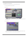
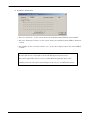
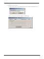
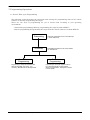


![[S3062PT-CPE-2] User`s Manual(First Edition): CPE62PSUE_2](http://vs1.manualzilla.com/store/data/005668190_1-0d028d6af383e5d06430420ca44dee4c-150x150.png)


![[S3062PT-CPE] User`s Manual(Third Edition): CPE62PUE](http://vs1.manualzilla.com/store/data/005693507_1-69a1045bbc5cf41449359b406d2a53f2-150x150.png)