1
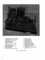
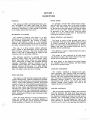
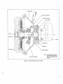
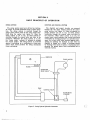
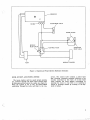
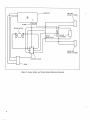
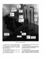
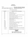
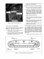
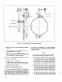
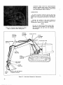
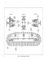
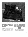
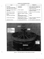
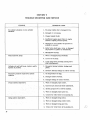
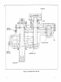
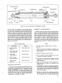
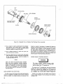
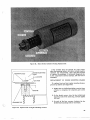
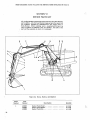
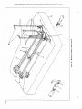
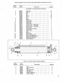
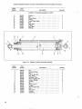
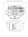
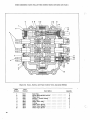
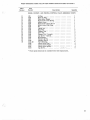
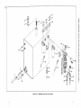
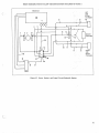
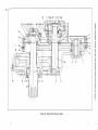
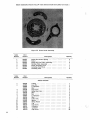
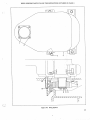
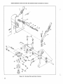
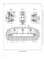
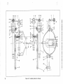
BULLETIN CE D-21
*0 0 R AI
Fklittop EQUIP-moit- DLG Is
OHAt*Lk.014.:I.53-
BULLETIN CED-21
service manual
HYDRAULIC EXCAVATORS
model
serial no.
Almost half a century of design and manufacturing experience has gone into your new
Hein-Werner machine. It is the finest equipment that this know-how and modern
technology can produce. We congratulate you on your selection.
We recommend that you become familiar with this manual and the maintenance procedures outlined herein. Following these instructions and operating the machine in a
proper manner will assure you of long, dependable and profitable service.
hfoineimir
CORPORATION
CONSTRUCTION EQUIPMENT DIVISION
WAUKESHA, WISCONSIN 53187
INSTRUCTIONS FOR ORDERING REPLACEMENT PARTS
To assure prompt and accurate service,,.ihciude the following data
• with each parts order:
1.
2.
3.
4.
5.
6.
Model and Serial number of machine
Part numbers
Part descriptions
Quantity of each part desired
Correct shipping destination
Method of transportation
Confirm all telephone and telegraph orders in writing. Be sure these
orders are marked "Confirmation," to avoid duplication of orders.
WHERE TO ORDER PARTS
Hein-Werner Dealers are conveniently located throughout the United
States and Canada. These Dealers maintain a stock of genuine HeinWerner replacement parts. Always order parts from your nearest
Hein-Werner Dealer.
INSPECTION OF SHIPMENTS
Carefully inspect all shipments upon arrival. In the event of loss or
damage, do not accept the shipment until the transportation company
either makes a notation on the freight bill, or gives you an inspection
report covering said damage or loss. In the event of concealed damage
or loss, notify the carrier at once (within 20 days) requesting that an
inspection be made and damage or loss be acknowledged.
ADJUSTMENTS AND RETURNS
Refer to the written Warranty in this manual for an explanation of
Warranty policy. If you feel a Warranty claim is in order, consult your
Dealer. Claims must be made through your Dealer within a 15 day period
from the time a failure occurs. Parts returned directly to the factory,
without Dealer Authorization, will not be accepted.
USE ONLY GENUINE HEIN-WERNER PARTS FOR MAXIMUM PERFORMANCE
TABLE OF CONTENTS
Hein-Werner Hydraulic Excavator Models. C-10, C-10HD and C-12
Page
SECTION I - DESCRIPTION
1
SECTION II - BASIC PRINCIPLES OF OPERATION
4
SECTION III - OPERATION. • .
Preparation for Use . .
Starting the Engine
Use of Controls
Digging Hints
Use of Attachments
Stopping the Engine.
Preparation for Storage .
7
7
7
. OOOOOOOOOOO
O • . .• • .
• • • OOOOOOOOO . • • • • • .
• •
O
OOOO OOO OOO ••• • •
10
10
SECTION IV - MAINTENANCE
Inspection Schedule. OOOOO . OOOOOOOOO .
Propel Drive Chain Adjustment
Crawler Track and Drive Chain Adjustment
Crawler Brake and Jaw Clutch Adjustment OO .
Control Valve Pressure Check . . . . . ...
Ltibrication
SECTION V - TROUBLE SHOOTING AND SERVICE . . .
Trouble Shooting Guide ........ . . ... . .
G ear Box Service. . . ...... . . . . . . . . . .
.
Hydraulic Cylinder Service . . . . .
Replacement of ,Pivot Pins
. Brake Cylinder Service
Replacement of Engine Mounts
SECTION VI - REPAIR PARTS LISTS
9
9
9
9
11
11
11
12
14
. .
.
.
21
22
22
23
24
iii
1. Swing system hydraulic pump section
2. Dipstick and propel system hydraulic
pump section
3. Boom, propel, and bucket system
hydraulic pump section
4. Hydraulic reservoir
5. Boom, propel, and bucket system
filter
6. Dipstick and propel system filter
7. Swing system filter
8. Swing system hydraulic motor
9. House brake cylinder
10. House brake drum
11. Propel system chain driven sprocket
12.
13.
14.
15.
16.
17.
18.
19.
20.
21.
22.
Speed travel lever
Power travel lever
Boom control lever
Bucket control lever
Swing control lever
Dipstick control lever
Bucket control foot pedal
Dipstick control foot pedal
Swing system relief valve
Swing system control valve
Boom, propel, and bucket system
control valve
23. Dipstick and propel system control
valve
Figure 1. Machinery Platform
iv
SECTION I
DESCRIPTION
GENERAL
HOUSE BRAKE
This manual provides .operating instructions, service information, and repair parts lists, for Model
C-10, C-10HD, and C-12 crawler-mounted hydraulic
excavators. Information in this 'manual is applicable
to all models unless otherwise noted.
An .automatic "house brake" safety feature eliminates all drift and creep, even in the event of engine
failure. The house brake is automatically actuated
by spring force when the operator, releases the swing
lever or for any other reason that causes a lack
of .pressure to the swing circuit. When the swing
circuit is in use, the house brake is automatically
released by hydraulic pressure.
MACHINERY PLATFORM
The machinery platform (see figure 1) is fully
reinforced at stress points to provide a rigid base
for operating components. The location of components on the platform results in a well balanced
rotating unit, and provides easy access for servicing
all parts including hydraulic lines and connections.
The use of a three section tandem hydraulic
pump, results in the elimination of gear drives and
thus increases efficiency. This also provides each
control valve with an independent oil supply for top
response under all operating conditions.
The hydraulic reservoir is equipped with three
separate suction hoses and three separate return
hoses. The three return hoses are each equipped
with a safety-flow oil filter with cleanable filtering
elements. Disposable filtering elements are also
available. Each filter has a back-pressure gage to
indicate filtering effectiveness. If a filter element
becomes clogged, the automatic by-pass valve in the
filter will open to allow the oil to circulate.
SWING BEARING
The double row ball bearing swing bearing results in
greater effectiveness, reduced maintenance, smoother
rotation, and the elimination of such parts asking pins,
rollers, roller paths, bushings, brackets, nuts, thrust
washers, shims, etc. This greatly increased effectiveness is a result of the swing bearing's ability to absorb all axial, radial, and tilting forces; and to distribute them over a much wider area than is possible with
conventional rollers. The swing bearing is bolted together to form a completely enclosed unit which eliminates adjustments and day-to-day maintenance other
than lubrication.
Since the swing bearing is the only connection between the carbody and the machinery platform it
eliminates any rocking motion except that permitted
by the carbody as it moves over the terrain.
BOOM, DIPSTICK, AND BUCKET
The boom is made of high strength steel and is
of extremely deep box section. Boom flange strength
is further increased by the addition of an internal
plate, and extra large reinforcing plates at the top,
bottom, and sides which extend beyond the area of
greatest stress concentration.
The dipstick is made of high strength steel and is
internally reinforced.
The bucket is also reinforced at all high stress
concentration points. The bucket teeth are pin connected and are individually replaceable.
All pivot points of the dipstick and bucket linkage
are equipped with steel bushings and heat treated
pivot pins to minimize wear.
CRAWLER UNDERBODY
The crawler underbody is equipped with splitchain sprockets, self cleaning tread and tumblers,
and centrally located lubrication points on the side
frames. The fully enclosed track adjustment eliminates "freezing". Double-flange track rollers provide
maximum bearing surface in wear areas. Heavy
ship-channel side frames, extra heavy shoes, and
involute splined power shafting, are proof of its
rugged, job-proven construction.
CAB AND CONTROLS
The cab provides excellent visibility and protection
from the elements. The large front glass panel can
easily be removed. All control lever linkage is above
the machinery platform and away from mud and dirt.
Controls are conveniently located and swing and
boom levers can be interchanged for right or left
hand operation if desired. The bucket and dipstick
controls can be hand or foot operated (see figure 1).
The seat is adjustable in three directions. Instruments
are conveniently grouped beneath the cab front window and includes an ammeter, fuel gage, oil pressure gage, and water temperature gage. An hour
meter is mounted at the rear of the cab.
GEAR BOXES
Swing system and propel system gear boxes are
precision bored and milled to assure precise gear
line up for smooth long-life power transmission.
All gears and shafts are accurately cut from alloy
steel and heat treated. Shafts are carried by tapered
roller bearings. The swing gear box is doweled to
the machinery platform with specially ground studs
which assures perfect mesh between the swing pinion
and the swing gear at all times. The position of the
propel box is adjustable to compensate for drive
chain wear so that the correct chain slack can be
maintained.
HYDRAULIC CYLINDERS
All hydraulic cylinders, with the exception of the
house brake cylinder, are double acting. Cylinders
are equipped with "V" type packings contained in
bronze adapters. The bronze adapters eliminate direct contact between piston and cylinder walls and
between cylinder rod and rod guide. Cylinder walls
are honed to a fine finish. Piston rods are chrome
plated, high carbon, specially treated alloy steel.
VALVES
All control valves have excellent "feathering"
characteristics to assure smooth operation. All control valves are spring loaded to return to neutral
position when the pressure on the control lever is
released. Relief valves protect all hydraulic systems
from overloading.
TOOL KIT
A tool kit is furnished with each machine and
includes:
1 - Grease Gun
1 - Spanner Wrench
1 - 7/8" and 1" Open End Wrench
1 - 1-1/4" Open End Wrench
1 - 3/4" Drive Universal Joint
1 - Deep Throat 3/4" Drive 1-1/16" Socket
1 - Deep Throat 3/4" Drive 1-1/8" Socket
1 - Standard 3/4" Drive 15/16" Socket
1 - 3/4" Drive 12" Extension
1 - 15" Crescent Wrench
1 - 1-1/2" Special Tube Wrench
1 - Standard Sliding T 3/4" Drive
1 - Standard 3/4" Drive 1-13/16" Socket
1 - 1-3/8" Open End Wrench
ENGINE
Power is supplied by either a gasoline or diesel
engine. The make of engine is optional. Refer to the
engine manual provided with your machine for operating instructions, service information, and repair
parts lists.
HYDRAULIC PUMP DRIVE
The three section tandem hydraulic pump is driven
using either a solid drive shaft, or a clutch (see
figure 2). The clutch is optional equipment and
varies depending upon the engine used to power the
machine. If your machine is equipped with a clutch,
refer to the clutch kit parts list which is enclosed
with this manual.
COVER PLATE
CLUTCH HOUSING
GREASE FITTING
SNAP RING
SHAFT
BEARING
PUMP
SNAP RING
BEARING
FLYWHEEL
PUMP ADAPTER
CLUTCH ASSEMBLY
NOTE: CLUTCH SHOWN ABOVE
IS OPTIONAL; SEE PAGE
56 FOR STANDARD PUMP
DRIVES.
Figure 2. Cross-Sectional View of Clutch
3
SECTION II
BASIC PRINCIPLES OF OPERATION
SWING SYSTEM
DIPSTICK AND PROPEL SYSTEM
The swing system gear box is driven by a hydraulic motor to provide unlimited swing in either direction. The swing system is powered through the
single spool control valve by the pump section fur. thest from the engine (see figure 3). When the
swing system is not in use, oil flows without restriction through the control valve and filter to the
reservoir. Whenever the swing system is in use,
the "house brake" cylinder is actuated to release
the "house brake". The swing system is protected
against overloading by a cushioning or cross-over
relief valve which protects the swing mechanism
from overloading.
The dipstick and propel circuits are powered
through the two spool control valve by the center
pump section (see figure 4). When the dipstick or
propel systems are not in use, oil flows without
restriction through the control valve and filter to
the reservoir. When, either circuit is in use, the
control valve relief protects that circuit from being
overloaded by limiting pressure to a specified maximum. An in-line relief valve protects against overloading by allowing the dipstick to open when the
dipstick is loaded as a result of leverage caused
by working of the boom or bucket. A cushioning valve
protects the propel motor from overloading due to
external reasons.
RESERVOIR
SWING MOTOR
0
FILTERS
CROSSOVER
RELIEF VALVE
...
PUMP
\ CONTROL VALVE
HOUSE BRAKE
CYLINDER
1_1
Figure 3. Swing System Hydraulic Schematic
4
RESERVOIR
0
0
FILTERS -..
)(3
-)
BOOM RELIEF VALVE
PROPEL MOTOR
DIPSTICK
RELIEF VALVE
CROSSOVER
RELIEF VALVE
CONTROL VALVE
DIPSTICK CYLINDER
PUMP
Figure 4. Dipstick and Propel System Hydraulic Schematic
BOOM, BUCKET, AND PROPEL SYSTEM
The boom, bucket, and two speed propel systems
are powered through the three spool control valve
by the pump section nearest the engine (see figure 5).
When the system is not in use, oil flows without
restriction through the valve and filter to the res-
ervoir. The control valve contains a relief valve
that prevents excessive pressure build-up in the
circuits controlled by this valve. An in-line relief
valve protects the boom against overloading by
allowing the boom to rise when it is loaded as a
result of leverage caused by working of the dipstick or bucket.
5
RESERVOIR
LEFT SIDE
BOOM CYLINDER
0
FILTERS
PROPEL MOTOR
e•■
••••••■■1"
N
P-1: 01
BOOM
RELIEF VALVE
BUCKET
CYLINDER
I 4.--1
I-
+
CONTROL VALVE
PUMP
Figure 5. Boom, Bucket, and Propel System Hydraulic Schematic
6
RIGHT SIDE
BOOM CYLINDER
SECTION III
OPERATION
PREPARATION FOR USE
USE OF OPERATING CONTROLS
Inspect the machine for security of fuel, hydraulic,
and electrical connections. Tighten connections or
attaching parts as required. Check engine belt tension. Inspect for evidence of damage which may have
occurred during shipment. Operate all controls to
be sure they are operating freely.
All control valves have excellent "feathering"
characteristics to assure smooth operation and are
spring loaded to return to neutral position when
pressure is released on control lever. Apply gradual
pressure to operate control levers and maintain a
slight pressure on control levers when moving them
to neutral position.
Check oil level in hydraulic reservoir by removing
high level plug in end of reservoir. Oil level in
reservoir must not exceed high level plug and must
not be lower than low level plug. If necessary, add
oil conforming to specifications in Section IV.
Check level of lubricant in swing and propel gear
boxes. If necessary, add lubricant conforming to specifications in Section IV.
Check fuel supply and fill fuel tank with fuel conforming to specifications in engine service manual.
NOTE
Operators not familiar with hydraulic machines may tend to over-control and cause
rough operation of the machine. It is recommended that the machine be operated at
hall throttle or less until the operator gets
the "feel" of the controls. The throttle setting
may then be gradually increased to full governed speed as the operator becomes more
familiar with the control system and control
valve feathering characteristics.
Check coolant level and add as necessary.
Use of Boom Control LeverCheck air cleaner in accordance with instructions
in engine service manual. Clean or add oil as required.
To raise boom, pull boom control lever (figure 6)
back.
Check engine oil level and add oil as required
according to specifications in engine service manual.
To hold boom in- position; move control lever to
center position (neutral).
Check level of electrolyte in battery and add clean
or distilled water as required. Check battery and
terminals for corrosion and clean as required.
To lower boom; push boom control lever forward.
Lubricate all points as specified in Section IV and
in engine service manual.
NOTE
After four to eight hours of initial operation,
hydraulic cylinder packing flanges must be
tightened to prevent excessive escape of hydraulic oil around the cylinder rods. Do not
overtighten, as a small seepage of oil at these
points is necessary for cylinder rod lubrication.
Use of Bucket Control Pedal or Lever
For normal operation, use bucket foot pedal to
operate bucket. However, for very close work when
speed is not a factor, use bucket control lever to
control critical movement of bucket (see figure 6).
To place bucket in closed position, 'push down with
heel of left foot on bucket • control foot pedal, or
pull bucket control lever back.
To hold bucket in position, move bucket control
foot pedal or lever to center position (neutral).
To place bucket in open position, push down with
toe of left foot on bucket control foot pedal, or push
bucket control lever forward.
Use of Dipstick Control Pedal or Lever
STARTING THE ENGINE
Leave all control levers in neutral. Place throttle
in approximately half-fuel position. Place ON-OFF
switch in ON position or place fuel shut-off lever
in RUN position. Depress starter button to crank
engine. If engine fails to start after two or three
cranking attempts, refer to engine service manual
for cause of trouble and instructions to correct it.
For normal operation, use dipstick control foot
pedal to operate dipstick. However, for very close
work when speed is not a factor, use dipstick control
lever to control critical movement of dipstick (see
figure 6).
To tuck dipstick in, push down with heel of right
foot on dipstick control foot pedal, or pull dipstick
lever back.
7
SWING
CONTROL
LEVER
BOOM
CONTROL
LEVER
THROTTLE
CHOKE OR
FUEL SHUT-OFF
LEFT
SIDE TRACK
STEERING
LEVER
DIPSTICK
CONTROL
LEVER
BUCKET
CONTROL
LEVER
SPEED
TRAVEL
LEVER
RIGHT
SIDE TRACK
STEERING
LEVER
POWER
TRAVEL
LEVER
LEFT HAND
SWING
LEVER
CONNECTION
BUCKET
CONTROL
FOOT PEDAL
SEAT FORWARD
AND REVERSE
ADJUSTMENT
DIPSTICK
CONTROL
FOOT
PEDAL
SEAT HEIGHT
ADJUSTMENT
RIGHT HAND
BOOM LEVER
CONNECTION
Figure 6. Operating Controls
To hold dipstick in place, move dipstick control
foot pedal or lever to center position (neutral).
To swing platform in a counterclockwise direction,
push control lever forward.
To open dipstick, push down with toe of the right
foot on dipstick control foot pedal, or push dipstick
control lever, forward.
The swing and propel systems operate independently
of each other. Therefore, the swing system can be
operated while the unit is being propelled.
Use of Swing Control Lever
To swing platform in a clockwise direction, pull
swing control lever (figure 6) back.
Use of Propelling Controls
To hold platform in position move swing control
lever to center position (neutral).
8
To propel machine straight ahead, (drive sprockets to the rear), place both steering levers in upper
position to engage jaw clutches and release drive
brakes. Push right hand travel lever forward. To
increase propelling speed, also push left hand travel
lever forward. To propel machine straight backwards,
follow same procedure, except pull travel lever(s)
back.
from 16 to 48 inches. A 60 inch wide ditch bucket
is available for ditch cleaning or material handling,
and can also be used in either backhoe or shovel
position.
To propel machine ahead and to the right, place
only left side track steering lever in upper position
and push right hand travel lever forward. To increase
propelling speed, also push left hand travel lever
forward. To propel machine backwards and to the
right, follow same procedure, except pull travel
lever(s) back.
Also available are a clamshell bucket, a log grab,
a pulpwood grapple and a frost point.
To propel machine ahead and to the left, place
only right side steering lever in upper position and
push right hand travel lever forward. To increase
propelling speed, also push left hand travel lever
forward. To propel machine backwards and to the
right, follow same procedure, except pull travel
lever(s) back.
When traveling straight forwards or backwards,
relieve pressure on the travel lever(s) before using
either steering lever to turn machine. This is necessary to relieve pressure on jaw clutches so they will
disengage easily.
When performing digging operations, both steering
levers must be pushed forward and set to apply both
track drive brakes and prevent movement of the unit.
This procedure may not be necessary in many cases
where the machine will remain stationary while digging
in loose materials.
DIGGING HINTS
Keep the work as close to the machine as possible.
This results in a greater mechanical advantage and
also cuts down the cycle time. By starting a cut
with the dipstick at right angles to the boom point,
cycle time can be decreased because the boom does
not have to be repositioned as often.
By tucking the dipstick as the boom is raised
out of a cut, the top of the cut can be cleared sooner
cutting down cycle time. Square cuts for manholes,
etc., can be made easier by moving the machine
in-line with each bank, rather than using the swing to
get from bank to bank. Straight down end cuts can
be made by extending the dipstick and bucket and
moving the machine forward or back to reach the
bottom of the cut. To decrease cycle time, especially
in a deep cut, shave off a layer at a time, rather
than going to the bottom of the cut on every cycle.
Rocks and stumps can be uncovered, undermined,
and pried out using the bucket.
For faster dumping, open both the bucket and the
dipstick. When digging in gravel, stones, or shale,
use the bucket teeth to loosen the material so that
the bucket can be filled on the next cycle. When
digging in clay or hard soil, use the bucket in a flat
position and shave or peel the soil by moving the
boom and dipstick.
USE OF ATTACHMENTS
The bucket can be removed and reattached in an
inverted position to use the machine for shovel
operation. Digging buckets are available in widths
STOPPING THE ENGINE
Reduce engine speed to idle. Allow engine to
operate at idle speed for approximately five minutes
to normalize engine temperature before placing ONOFF switch or fuel shut off lever in OFF position
to stop engine. If the engine continues to run after
the fuel shut-off lever is placed in OFF position,
pull emergency stop knob located on back wall of
cab. This will shut off the air supply to the engine
by tripping the air shut-off valve. If air shut-off
valve has been tripped, it must be reset before
the engine can be operated. To reset the air shut-off
valve, first push the emergency stop knob all the
way in, and then manually reset the air shut-off
valve latch.
NOTE
Sudden stoppage of the engine is not recommended unless absolutely necessary.
PREPARATION FOR STORAGE
If the machine is to be stored for an indefinite
length of time, the following procedures are recommended, subject to the anticipated storage period.
1. Drain fuel system and refill with Valvoline Oil
Company "Tectyl 503-C" rust preventative compound or its equivalent.
2. Drain engine lubricant and refill with engine
preservative oil.
3. Drain engine cooling system and refill with corrosion inhibitor.
4. Crank engine to circulate preservative oils
through fuel and lubricating systems.
5. Drain lubricant from swing and propel gear boxes
and refill with preservative oil.
Wherever fluid systems have been drained,
a waterproof tag should he affixed to the tank
or engine, cautioning operator not to operate
the machine until system(s) have been drained
and refilled with correct operating fluid.
6. Remove battery.
7. Relieve engine belt tension. Tag belts indicating
that belt tension must be adjusted before starting engine.
8. Wipe machine to remove film and dirt. Apply
preservative to any exposed metal surfaces
subject to corrosion through prolonged nonusage, such as valve spools, cylinder rods, etc.
9. Close and secure all doors. Seal all openings
with waterproof paper.
10. Fill hydraulic system completely with hydraulic
oil.
SECTION IV
MAINTENANCE
GENERAL
Proper care and operation of your machine will
prevent unnecessary repairs and downtime. This
section contains a periodic inspection schedule along
with necessary operating adjustments, and lubrication
recommendations, which will help you to get the optimum performance from your machine.
PERIODIC INSPECTION SCHEDULE
FREQUENCY
INSPECTION OR SERVICE TO BE PERFORMED
Daily
Lubricate as required.
Daily
Check engine lubricating oil supply.
Daily
Check engine coolant supply.
Daily
Inspect for and correct any fuel, oil, coolant, or hydraulic system leaks.
Daily
Check level of hydraulic oil in reservoir.
Daily
Check level of lubricant in propel and swing system gear boxes.
Daily
Check level of electrolyte in battery coils.
Daily
Check back pressure indication on filter gages; clean or replace
elements as necessary.
Daily
Check engine drive belt tension.
Weekly
Lubricate as required.
Monthly
Check slack in propel system drive chains; adjust as required.
Monthly
Inspect propel system brakes; adjust as required.
Monthly
Check hydraulic system pressures.
Monthly
Check all mechanical linkage connections.
Monthly
Inspect all hydraulic system hoses for signs of possible trouble.
Monthly
Tighten any loose mounting bolts or nuts.
As required
Inspect bucket teeth and replace as necessary. Do not use shanks without
teeth for digging.
As required
Remove filler screen from hydraulic reservoir. Clean screen thoroughly
with cleaning solvent and replace in reservoir.
CAUTION
Filler screen should be removed only for
cleaning and must always be in place when
filling or adding oil to hydraulic reservoir.
10
3. Tighten both adjusting bolt lock nuts and then
tighten gear box mounting bolts.
CRAWLER TRACK AND DRIVE CHAIN ADJUSTMENT
1. Remove cotter pins and lock pins on each side
of tracks at drive sprocket end (see figure 8).
2. Adjust the track adjusting nut until there is
7/16-11/16 inch deflection in drive chain. Adjust
both adjusting nuts equally to keep the tumblers and drive sprocket in proper alignment.
(Note: It may be necessary to loosen the track
adjusting nuts at idler end to obtain sufficient
slack to tighten the drive chain).
3. Replace lock pins and cotter pins.
4. Remove the cotter pins and lock pins from the
track adjusting nut on each side of the tracks
at idler end.
5. Adjust the track tension until some slack exists.
(Note: Adjust both adjusting nuts equally to keep
the tumblers in proper alignment).
Figure 7. Propel Drive Chain Adjustment
6. Replace lock pins and cotter pins. (Note: Chain
and track must not be tight).
CRAWLER BRAKE AND JAW CLUTCH ADJUSTMENT
PROPEL DRIVE CHAIN ADJUSTMENT
Check propel drive chain for 7/16 to 11/16 inch
deflection on slack side of chain (see figure 7).
If necessary to adjust, proceed as follows:
1. Loosen propel gear box mounting bolts which
attach gear box to mounting frame.
2. Loosen both adjusting bolt lock nuts and tighten
each adjusting bolt equally to adjust chain
until deflection is 7/16 to 11/16 inch.
TRACK
ADJUSTING NUT
DRIVE
SPROCKET END
LOCK PIN AND
COTTER PIN
To compensate for brake lining wear it is necessary to periodically adjust crawler brake linkage.
Brake lining wear will be indicated when the brake
and clutch levers travel too far down the ratchet
and the braking action is not sufficient. Since the
same levers control the jaw clutches, it is necessary to check the jaw clutch clearance when adjusting
brakes. If necessary to adjust, proceed as follows:
(See figure 9.)
1. Release crawler brake and engage jaw clutch.
TRACK
ADJUSTING NUT
LOCK PIN AND
COTTER PIN
IDLER END
Figure 8. Crawler Track and Drive Chain Adjustment
11
Figure 9. Crawler Brake and Jaw Brake Adjustment
2. Remove cotter pin from trunnion and remove
pivot pin.
in the event of malfunction of the unit and also at
periodic intervals, the pressure settings should be
checked as follows:
3. Rotate trunnion in a clockwise direction to
obtain sufficient braking power.
NOTE
4. Check for 1/8 inch minimum clearance between stationary and sliding members of the
jaw clutch when the brake is applied.
If this 1/8 inch minimum clearance does not
exist, proceed as follows:
1. Remove castle nut cotter pin.
2. Tighten castle nut until proper clearance exists.
3. Place lever in travel position and check for
proper mesh of jaw clutch.
CONTROL VALVE PRESSURE CHECK
The correct control and relief valve adjustments
have been made before shipping from the factory.
Only factory and dealer representatives are authorized to adjust valve pressure settings. TAMPERING
WITH THE PRESSURE SETTINGS WILL RESULT IN
VOIDING THE WARRANTY OF THE UNIT. However,
12
Be sure gage is indicating correctly. Check
gage against master gage to insure accuracy.
1. Boom Circuit Pressure Check. Install 0-3000
psi pressure gage in boom cylinder testing
port (see figure 10). Run engine at full throttle
and pressurize boom cylinder rod end by pushing boom control lever forward. Boom cylinder
pressure gage should indicate 1650 to 1700 psi.
2. Bucket Circuit Pressure Check. Install 0-3000
psi pressure gage in bucket cylinder testing
port (see. figure 11). Run engine at full throttle
and, pressurize bucket cylinder rod end by pushing bucket control lever forward. Bucket cylinder
pressure gage should indicate 1650 to 1700 psi.
3. Dipstick Circuit Pressure Check. Install 0-3000
psi pressure gage in dipstick cylinder testing
port (see figure 12) at the base end of cylinder.
Figure 10. Pressure Gage Installed in
Boom Cylinder Testing Port
Run engine at full throttle and pressurize dipstick cylinder base end by pulling dipstick control lever back. Pressure gage in base end of
dipstick cylinder should indicate 1900-1950.
4. Propel Circuit Pressure Check. Place machine
so that forward and backward travel are completely blocked. Install 0-3000 psi pressure
gage in propel motor cross-over valve testing
port (see figure 13). Run engine at full throttle
with both steering levers in upper position
to engage jaw clutches and release brakes, : and
push right hand travel lever 'forward *to pressurize propel circuit for forward travel. Pressure gage in forward travel testing port of
crossover valve should indicate 1900-1950 psi.
Figure 12. Pressure Gage Installed in
Dipstick Cylinder Testing Port
Figure 11. Pressure Gage Installed in
Bucket Cylinder Testing Port
Repeat same procedure,. except push left hand
travel lever forward to pressurize propel circuit. Pressure gage should indicate 1650-1700
psi.
5. Swing Circuit Pressure Check. Place unit so
that swing is completely blocked in both directions. Install. 0-3000 psi pressure gages in
swing motor crossover valve testing ports (see
figure .14). Run engine at full throttle and pressurize swing.- circuit for clockwise swing by
pulling swing control lever back.Pressure gage
in clockWise swing testing port • should indicate
1650 to 1700 psi. Run engine at full throttle and
Figure 13. Pressure Gage Installed in Propel
Motor Crossover Valve Testing Port
13
pressurize swing circuit for counterclockwise
swing by pushing swing control lever forward.
Pressure gage in counterclockwise swing testing
port should indicate 1650 to 1700 psi.
LUBRICATION
To assure maximum efficiency and long life of the
machine, be sure to use the proper viscosity and
grade of the recommended lubricants or their equivalent.
Lubricate the machine at the points indicated in
figures 15, 16, 17 and 18. Lubricate engine as recommended in engine service manual.
NOTE
Be sure to remove any excess grease after
lubrication of the machine, or dirt and dust
will accumulate and may work into bushings
and bearings.
Figure 14. Pressure Gage Installed in Swing
Motor Crossover Valve Testing Port
DIPSTICK
BOOM LIFT PIN
CYLINDER
BASE PIN BOOM
CYLINDERS
ROD END
DIPSTICK
CYLINDER
ROD PIN
-
BUCKET CYLINDER
BASE PIN
1- 1" I BOOM PIVOT PIN
I
•
••
■=1::
• •••
• • .. --
—
DIPSTICK
PIVOT PIN
BOOM •
CYLINDERS
BASE END
, I
fi
111
,
,
I
- -- - 7 - - - - - - - -
BUCKET LINK AND BUCKET
CYLINDER ROD END
Figure 15. Lubrication Diagram for Upperworks
I
--•-
1
BUCKET
PIVOT PIN
14
I
I
1-1---)..-11-- 1
BELL CRANK
PIVOT PIN
BUCKET
LINK
I
1
•14 I
l‘m
Isr
C1 —1 AI
0E4
FRONT
SHAFT
OA0
4164 4fr''.'"4':1'
.
s:—,1 .:::-A
ki N ik
n .
4:\ Skis noau
A
lir
„Ar
TRACK
ADJUSTING
NUTS
At ikj 11.---ik---..1
ii.—,
4,sik
.......-0
1li,,-„-f------0,1/"."06
1
11
I
SECTION C-C
SECTION B-B
SECTION A-A
4,,,,,_,....,,,..,
?b....0
■
1.
IDLER
ROLLER
SHAFTS
naununtlifiar
..\-_.,
__r:i.t..•
_
TRACK
ADJUSTING
NUTS
nt.7,.---
IDLER
ROLLER
SHAFTS
REAR
SHAFT
REAR
SHAFT
IDLER
ROLLER
SHAFTS
Figure 16. Lubrication Diagram for Crawlers
FRONT
SHAFT
PUMP DRIVE
BEARING
PROPELLING
CONTROL SHAFTS
CONTROL
LEVERS
Figure 17. Lubrication Diagram for Machinery Platform
Do not lubricate crawler underbody propel drive
chains. Be sure to lubricate all lubrication points of
crawler underbody daily, even though the machine
has not been traveling, since there is movement when
digging and swinging.
Be sure to check indication of oil filter gages
daily. The filter element needs cleaning (cleanable
type) or replacement (disposable type) whenever the
gage needle indicates in the red range. If cleaning
or replacing one filter element, be sure to clean
or replace the other two elements at the same time.
16
When the machine is shipped from the factory,
the hydraulic system is filled with a premium grade
hydraulic oil which is compatible with any premium
grade SAE 20 mill or engine oil. When extreme
temperature conditions are encountered, consult the
factory for hydraulic system oil recommendations.
Do not, under any circumstances, dilute the
hydraulic system oil with kerosene. The hydraulic system components depend on the lubricating properties of the hydraulic system oil.
LUBRICATION RECOMMENDATIONS
FREQUENCY
LUBRICANT
PART
Gear boxes
EP 80-90 oil
Add as required to maintain level.
Cross-propel shaft housing
(filler pipe at front of carbody)
EP 80-90 oil
Add as required to maintain level.
Capacity is one quart.
Open gears and upper propel
drive chain
Crater compound.
Inspect visually twice daily. Apply
lubricant as required.
Swing bearing (4 fittings)
Mobilux GR #2 or equivalent.
Weekly. 1/4 to 1/2 lb. per fitting.
Gear box bearing grease
fittings
Mobil No. 5 grease, or equivalent.
Weekly.
Pump drive grease fitting
Moly type grease, such as
Mobiloil Special or equivalent.
Weekly.
All other grease fittings
Moly type grease, such as
Mobiloil Special or equivalent.
Daily or more often if required by
operation conditions.
Hydraulic reservoir
Premium grade SAE 20 oil.
Add as required to maintain level.
SHIFTERS
;
TEN GREASE
FITTINGS AND
CROSS PROPEL SHAFT
HOUSING FILLER PLUG
AT FRONT OF
CARBODY
PROPEL
SHAFT
TWO GREASE
FITTINGS AT
REAR OF
CARBODY
Figure 18. Lubrication Diagram for Swing Bearing and Carbody
17
SECTION V
TROUBLE SHOOTING AND SERVICE
TROUBLE
No cylinder actuation or slow cylinder
actuation.
PROBABLE CAUSE
1. No pump rotation due to damaged drive.
2. Damaged or worn pump.
3. Clogged supply line(s).
4. Insufficient engine speed (refer to engine
manual to adjust governed speed).
5. Damaged or worn cylinder (if pressure to
cylinder is correct.
6. Relief valve stuck open, worn, or damaged
(if pressure to cylinder is insufficient).
7. Misadjusted valve(s).
Noisy hydraulic pump.
1. Worn or damaged pump section(s).
2. Lack of oil to pump.
3. Loose pump drive mounting causing drive
shaft misalignment.
Cylinders do not hold boom, bucket, and/or
dipstick in position.
1. Excessive internal cylinder leakage past
piston.
2. Exessive internal leakage in control valve(s).
Excessive pressure required to operate
controls.
1. Oil temperature too high.
2. Damaged control valve(s).
3. Damaged linkage to control valve(s).
Propel system inoperative.
1. Worn or damaged propel motor.
2. Incorrect jaw clutch and brake adjustment.
3. Broken propel drive or driven chain(s).
4
Worn or damaged propel gear box.
5. Cross-over relief valve is by-passing oil.
Swing system inoperative.
. Worn or damaged swing motor.
. Worn or damaged swing control valve.
3. Worn or damaged swing gear box.
4. Cross-over relief valve is by-passing oil.
18
TROUBLE
Platform creeps or drifts when swing lever
is in neutral.
PROBABLE CAUSE
1. Broken spring(s) in brake cylinder.
2. Broken linkage to brake cylinder.
3. Brake shoes worn.
4. Internal leakage in swing control valve.
House brake will not release.
1. Broken supply line to brake cylinder.
Controls do not return to neutral when
released.
1. Broken return spring in control valve.
2. Sticky valve due to excessive oil temperature.
3. Binding in control lever assembly.
GEAR BOX SERVICE
The swing gear box and the propel gear box are
of similar construction, except for the brake on the
swing gear box. The following repair instructions
are applicable to both gear boxes except as noted.
Removal of Swing Gear Box
Lift the intermediate shaft, pinion, gear, and bearing assembly from the case. Remove the input drive
pinion and bearing assembly from the case.
Remove the snap ring from the output shaft and remove the final drive gear from the shaft. Remove the
output shaft and bearing from the case by driving it
out from the inside with a plastic hammer.
Drain lubricant from gear box. Use swing lever to
pressurize brake cylinder. Remove linkage which connects cylinder to gear box brake. Shut off engine and
disconnect hydraulic line to cylinder. Disconnect hydraulic connections to swing motor. Remove nuts and
lockwashers from four studs and remove gear box.
Remove remaining cups and oil seals from the case
with a puller.
Removal of Propel Gear Box
Place the intermediate shaft in a press and press
the intermediate driven gear and bearing from the
shaft. Reverse the shaft and press the other bearing
off with a puller.
Drain lubricant from gear box. Disconnect hydraulic
connections to propel motor. Open interconnecting
chain link and remove propel drive chain. Remove
bolts and nuts which attach gear box to mounting frame
and remove gear box.
Disassembly of Gear Boxes (see figure 19)
Remove swing and propel motors and house brake
cylinder. Remove brake drum from swing gear box.
Remove retaining ring and slide brake drum mounting
adapter from intermediate shaft. Remove brake shoe
return springs and brake shoes. Remove roller from
actuating pawl. Remove brake shoe lever. Remove
backing plate from gear box. Remove swing pinion from
swing gear box and remove chain sprocket from propel
gear box. Remove all bolts, nuts, and washers which
hold cover to case. Remove the output and intermediate
shaft covers from the gear box cover. Remove the nut
and washer from the output shaft.
The upper end bearing is a press fit on the output
shaft. Use of a puller to anchor on the cover and press
against the shaft is recommended to remove the bearing from the shaft. This will also lift the cover from
the case, which will expose all of the other gears and
shafts.
Place the output shaft in a. press with the threaded
end up and press the spacer, bearing and sleeve from
the shaft.
Inspection of Gear Box Components
Clean all components thoroughly. It is impossible
to overstress the importance of careful and thorough
inspection of drive unit parts prior to reassembly.
Thorough visual inspection for indications of wear,
and the replacement of such parts as are necessary
will eliminate costly and avoidable drive unit failure.
Inspect all bearings, cups and cones, including those
not removed from parts of the drive unit, and replace
if worn or damaged. Inspect gears for wear or damage.
Gears which are scored, pitted, ridged or worn must be
replaced. Hex nuts and bolts with rounded corners, all
lockwashers, oil seals and gaskets should be replaced
at the time of overhaul. Use only genuine Hein-Werner
replacement parts for satisfactory service. Remove
nicks, mars and burrs from machined or ground surfaces. Threads must be clean and free to obtain accurate adjustment and correct torque. Studs must be tight
prior to reassembling the parts.
Reassembly of Gear Boxes (see figure 19)
Reassembly of gear boxes is essentially the reverse
of disassembly. When assembling component parts use
a press where possible. Tighten all nuts and bolts to the
19
HOUSE BRAKE
J.IM11.11111MMej
AMIN"
SIM
ANON.
LUBRICANT
LEVEL PLUG
COVER
r.
I
r
r
CASE
•
INPUT DRIVE PINION
II—
LUBRICANT
DRAIN PLUG
INTERMEDIATE SHAFT
OUTPUT SHAFT
Figure 19. Cross-Sectional View of Gear Box
PACKING FLANGE
•
PISTON SLEEVE
STUD
ROD PACKING
CYLINDER TUBE
GREASE FITTING
PISTON
GLAND RING
GREASE FITTING
BUSHING
—
MIAM•
"1.2%1:141
:Si ma
V' '
1M EV IIMr
AMIN!,
atiol
tswat
■•■••/
1■P
ier
AK*
41111
i■
4/41/4111/11•
BUSHING
NUT
SHAFT SEAL
ROD
RAM HEAD
,
0-RING
NUT
• PISTON PACKING
0-RING
Figure 20. Cross-Sectional View of Hydraulic Cylinder
correct torque as specified in the gear box torque
chart. Use soft iron safety wire when replacing pinion
to output shaft. Intermediate shaft bearings are adjusted by means of shims under the intermediate shaft
cover. Use shims as required for 0.002 inch end play
to 0.002 inch preload. Output shaft bearings are adjusted by positioning the nut on the upper end of the output
shaft. Position and secure the nut as required for 0.002
inch end play to 0.002 inch preload. Install oil seals,
spacers, etc., as illustrated. Pack grease cavity of
output and intermediate shaft covers with Mobil No. 5
grease, or equivalent.
Gear Box Torque Chart
Description
Torque
Motor Mounting
Nuts (4)
106 to 113 ft. lbs.
Intermediate Shaft
Cover Bolts (6)
106 to 113 ft. lbs
Output Shaft
Cover Bolts (5)
69 to 73 ft. lbs.
Cover to Case
Bolts and Nuts (5)
118 to 128 ft. lbs.
Cover to Case
Bolts (14)
106 to 113 ft. lbs.
HYDRAULIC CYLINDER SERVICE
Cylinder repair kits consist of ram head and piston
sleeve 0-rings, rod packings and wiper, piston packing,
and rod nut. All parts of the repair kit should be used
when a cylinder is repaired, even though some of the
parts being replaced may not appear to be worn. It is
not necessary to remove a cylinder assembly from the
unit in order to repair it with a cylinder repair kit,
but extreme care must be taken to prevent the entry
of any dirt or foreign particles into the cylinder. Proceed as follows to service a cylinder: (See figures 20
and 21.)
NOTE
Use only factory approved parts to assure
proper fit.
1. Extend the bucket and dipstick completely and
lower the boom until the bucket is resting firmly
on the ground.
2. Remove mounting pin from rod end.
3. Use the spanner wrench supplied in the tool kit
to remove the cylinder ram head.
Replacement of Gear Boxes
Replacement of gear boxes is essentially the reverse
of removal. The swing gear box does not require any
positioning adjustment. Refer to PROPEL DRIVE
CHAIN ADJUSTMENT for proper positioning of the
propel gear box. Refer to lubrication specifications
and fill both gear boxes to the oil level plug. Inspect
carefully for any leaks and tighten connections or
replace hoses or fittings as required.
4. Use a hoist or jack to pivot the cylinder to allow
clearance for removal of the cylinder rod and
piston assembly.
5. Remove hoses from base end of cylinder to release any suction. Remove rod assembly from
cylinder tube.
6. Disassemble the cylinder rod and piston assembly
as indicated by figure 21. Replace packings, 0rings, wiper seal, and rod nut. Lubricate all parts
with hydraulic oil. Reassemble the cylinder rod
and piston assembly.
7. Replace the cylinder rod and piston assembly in
the cylinder and screw the ram head into the end
of the cylinder until it is tight. Replace hoses.
21
NUT
STUD
ROD PACKING
RAM HEAD ROD ASSEMBLY
PISTON
GLAND RING
PACKING FLANGE
WITH SHAFT SEAL
PISTON SLEEVE
WITH 0-RING
0-RJNG
NUT
PISTON PACKING
Figure 21. Exploded View of Cylinder Rod Packing Piston Assembly
8. Use a hoist or jack to slowly pivot the cylinder
into position. Use control lever to apply slight
hydraulic pressure to carefully align the rod end
with the cylinder rod end pivot point.
9. Use a plastic hammer to insert the pivot pin.
Lock the pivot pin in place.
10. Use the control levers to raise boom and slowly
apply hydraulic pressure alternately to both ends
of the repaired cylinder until the cylinder is
completely filled with oil.
NOTE
After 4 to 8 hours of operation with a cylinder
which has been repacked, cylinder packing
flanges must be tightened to prevent excessive
escape of hydraulic oil around the cylinder
rods. Do not overtighten as a small seepage
of oil at these points is necessary for cylinder
rod lubrication.
hoists or jacks if necessary to support the boom or
dipstick if supporting pivot pins are to be removed and
replaced. Use a plastic or brass hammer to remove
the pins. When replacing a pin, carefully examine the
pin bushings for evidence of wear or damage and replace these as necessary. Bushings are a press fit
and must be pressed out and in to prevent damage and
assure proper fit and operating clearance.
HOUSE BRAKE CYLINDER SERVICE
WARNING
The brake cylinder contains springs under
compression and is not to be serviced other
than to replace the "V" packing set.
REPLACEMENT OF PIVOT PINS
To remove the "V" packing set, unscrew the bronze
packing nut and remove packing set. Caution must be
used not to damage the cylinder rod. To replace the
"V" packing set, carefully slide the packing set over
the cylinder rod in the order shown in figure 22.
To allow removal of the pins, the bucket and dipstick
must be completely extended and the boom lowered
until the bucket is resting firmly on the ground. Use
Replace the packing nut and tighten only enough to
seal. A slight seepage of oil is necessary to lubricate
cylinder rod.
22
MALE ADAPTER
FABRIC SEAL
RUBBER SEAL
FEMALE ADAPTER
PACKING NUT
Figure 22. House Brake Cylinder Packing Replacement
'MOUNTING BOLT
ENGINE MOUNTING
FRAME
LOCKWIRE
5/16 INCH
.7401111r/
If the cylinder does not operate for some reason
other than packing failure, the entire cylinder must be
replaced. Any disassembly, other than that required
to replace the packings, is extremely dangerous due
to the compressed internal springs, and must not be
attempted.
REPLACEMENT OF ENGINE MOUNTING FRAMES
To replace front and rear engine mounting frames,
proceed as follows (see figure 23):
RETAINER
1. Tighten the two drilled head bolts on each of three
corners to compress the neoprene pad to 5/16
inch.
2. On the fourth corner, turn the two drilled head
mounting bolts down until snug, and then tighten
1/8 turn.
NEOPRENE PAD
3. On each of the four corners, lockwire the two
drilled head mounting bolts to each other.
Figure 23. Replacement of Engine Mounting Frames
23
WHEN ORDERING PARTS FOLLOW THE INSTRUCTIONS OUTLINED ON PAGE Ii
SECTION VI
REPAIR PARTS LIST
All six digit numbers appearing in this parts list are Hein-Werner
part numbers. All other part numbers appearing in this parts list
are numbers assigned by manufacturers who supply parts to
Hein-Werner. When ordering such a manufacturer's part, be
sure to-indicate, in addition to the part number, the name of the
part and the assembly in which it is contained.
Figure 24. Boom, Bucket, and Dipstick
24
Index
Number
Part
Number
1
400033
400034
400035
Description
Bucket Tooth Point
Bucket Tooth Shank
Bucket Tooth Pin
Quantity
as reqd
as reqd
as reqd
WHEN ORDERING PARTS FOLLOW THE INSTRUCTIONS OUTLINED ON PAGE ii
Index
Number
Part
Number
Description
Quantity
BOOM, BUCKET, AND DIPSTICK (CONT)
2
3
4
5
6
7
8
9
10
11
12
13
14
15
16
17
18
19
20
210024
150003
140027
220028
220027
040049
400018
400026
110045
110045
110052
220028
210002
030039
030039
030166
210002
040050
100053
100081
100081
030022
030023
030024
030162
030162
400254
400043
220000
210028
030036
030164
030164
210003
210004
040051
040059
040059
030038
030036
210027
210002
400015
Bucket and Linkage Pin
Bucket Link Assembly '
Bell Crank Link Assembly
Bell Crank Bushing - Not Grooved
Bell Crank Bushing - Grooved
Bucket Cylinder Assembly
Lock Pin
Cotter Pin
Dipstick (C-10)
Dipstick (C-10HD)
Dipstick (C-12)
Dipstick Pivot Bushing
Bucket Cylinder Base Pin
Bucket Cylinder Hose (C-10)
Bucket Cylinder Hose (C-10HD)
Bucket Cylinder Hose (C-12)
Dipstick Rod Pin
Dipstick Cylinder
Boom Assembly (C-10)
Boom Assembly (C-10HD)
Boom Assembly (C-12)
Boom Tube - Outer
Boom Tube - Inner
Boom Tube - To Bucket Cylinder Hose (C-10) . . .
Boom Tube - To Bucket Cylinder Hose (C-10HD) .
Boom Tube - To Bucket Cylinder Hose (C-12) . . .
Boom Double Tube Clamps (Top and Bottom). . . .
Boom Single Tube Clamps
Boom and Dipstick Pivot Bushing
Dipstick Cylinder Base Pin
Dipstick Cylinder Hose (C-10)
Dipstick Cylinder Hose (C-10HD). . .
.....
Dipstick Cylinder Hose (C-12) ...
• •
Boom Lift Pin
Boom Lift Pin Collar
Boom Cylinder Assembly (C-10)
Boom Cylinder Assembly (C-10HD)
••••
• .
Boom Cylinder Assembly (C-12) ..
.. .
Boom Cylinder Hose
Boom Foot Hose
Boom Foot Pin
Boom Cylinder Base Pin
Grease Fitting
5
1
2
2
2
1
14
14
1
1
1
6
1
2
2
2
1
1
1
1
1
2
2
2
2
2
6
6
8
1
2
2
2
1
1
2
2
2
4
4
1
2
9
25
Machinery Platform WithControls
WHEN ORDERING PARTS FOLLOW THE INSTRUCTIONS OUTLINED ON PAGE ii
26
WHEN ORDERING PARTS FOLLOW THE INSTRUCTIONS OUTLINED ON PAGE ii
Index
Number
Part
Number
Description
Quantity
MACHINERY PLATFORM WITH CONTROLS
1
2
3
4
5
400027
400024
400122
400121
400106
400023
400048
330024
330023
330076
330077
330078
330080
000011
000013
000012
330079
330068
330075
330059
330028
400006
120039
330042
330070
330017
120169
400005
6
7
8
9
10
11
12
13
14
15
16
17
18
19
20
21
22
23
24
14
14
8
Cotter Pin
Yoke Pin
Yoke
Nut
Bolt
Washer
Nut
Shaft
Spacer
Control Rod
Control Rod
Control Rod
Control Rod
Control Valve - Single Spool
Control Valve - Two Spool
Control Valve - Three Spool
Control Rod
Control Shaft Assembly
Control Rod
Travel Lever
Base
Setscrew
Handle Grip
Boom and Swing Lever
Bucket and Dipstick Lever
Control Base Assembly
Machinery Platform
Grease Fitting
8
20
20
20
1
2
1
1
1
1
1
1
1
1
1
2
2
1
2
6
2
2
1
1
8
ww,r4rurArArAmmir.carArarmanurearemurAwinormArAmmir 4rAgrArAmpreArmeArAirmAuramorn warm.
NERI
/A Nig
/AM/ AIKOMPZ
drAVAT
AVI /
214'■
.1
Figure 26. Bucket Cylinder Assembly (040049)
Index
Number
1
2
3
4
5
6
7
8
Part
Number
400013
040015
400001
010002
020101
040041
010006
400015
Description
Nut
Packing Flange
Stud
Rod Packing Set
Pipe Plug
Cylinder Tube
Piston Packing Set
Grease Fitting
Quantity
2
1
2
1
1
1
2
2
27
WHEN ORDERING PARTS FOLLOW THE INSTRUCTIONS OUTLINED ON PAGE ii
Part
Number
Indek
Number
Description
Quantity
BUCKET CYLINDER ASSEMBLY (CONT)
9
10
11
12
13
14
15
16
17
18
220000
400011
040023
010013
040022
040032
040005
010014
010010
220026
Bushing
Nut
Piston Sleeve
0-Ring
Piston Gland Ring
Rod
Ram Head
0-Ring
Shaft Seal
Bushing
2
1
1
1
1
1
1
1
1
2
lir
1
jiL=1===
$
=11=7111111
■111$
ilr'ZritrIrAirAimarAwarAwarArAnwainuri wArAirAinsimamarAmminarrAimer■AtanarriAi%
"';'"017.ii7ccfam
.1
b,
;.■nutileININIIIAIMPAINPAIIIIAWAIIVAIIIAll
ii••
1410
,411M
4111/4■
4111211521111%
Figure 27. Dipstick Cylinder Assembly (040050)
28
Index
Number
Part
Number
1
2
3
4
5
6
7
8
9
10
11
12
13
14
15
16
17
400013
040015
400001
010002
020101
040044
010006
400015
220000
400011
040023
010013
040022
040030
040005
010014
010010
Description
Nut
Packing Flange ..... . . .
Stud
Rod Packing Set
Pipe Plug
Cylinder Tube
Piston Packing Set
Grease Fitting
Bushing
Nut
Piston Sleeve
0-Ring
Piston Gland Ring
Rod
Ram Head
0-Ring
Shaft Seal
Quantity
2
1
2
1
2
1
2
2
4
1
1
1
1
1
1
1
1
WHEN ORDERING PARTS FOLLOW THE INSTRUCTIONS OUTLINED ON PAGE ii
Figure 28. Boom Cylinder Assembly
Index
Number
Part
Number
Description
Quantity
BOOM CYLINDER ASSEMBLY - 4 INCH
(040051)
1
2
3
4
5
6
7
8
9
10
11
12
13
14
15
16
17
400014
040014
400000
010004
020101
040042
040024
010005
400015
220000
400012
040025
010011
040031
040006
010012
010009
Nut
Packing Flange
Stud
Rod Packing Set
Pipe Plug
Cylinder Tube
Piston Gland Ring
Piston Packing Set
Grease Fitting
Bushing
Nut
Piston Sleeve
0-Ring
Rod
Ram Head
0-Ring
Shaft Seal
1
2
1
1
1
1
2
2
4
1
1
1
1
1
1
1
BOOM CYLINDER ASSEMBLY- 5-1/4 INCH
(040059)
1
2
3
4
5
6
7
8
9
10
11
12
13
14
15
16
17
400013
040015
400001
010002
020101
040063
040022
010006
400015
220000
400011
040023
010013
040058
040005
010014
010010
Nut
Packing Flange
Stud
Rod Packing Set
Pipe Plug
Cylinder Tube
Piston Gland Ring
Piston Packing Set ........... . • . . • .
Grease Fitting
Bushing
Nut
Piston Sleeve
0-Ring
Rod
Ram Head
0-Ring
Shaft Seal
2
1
2
1
1
1
1
2
2
4
1
1
1
1
1
1
1
29
WHEN ORDERING PARTS FOLLOW THE INSTRUCTIONS OUTLINED ON PAGE ii
Figure 29. House Brake Cylinder Packing
Index
Number
Part
Number
1
2
230068
010024
Index
Number
Part
Number
Description
Rod Packing Nut
Packing Set
Quantity
1
1
Description
Quantity
HOUSE BRAKE INSTALLATION
1
2
3
4
5
6
7
30
400208
230064
400207
400099
230062
400210
230051
Clevis. Pin
Brake Cylinder
Clevis Pin
Cotter Pin
Cylinder Support
Cap Screw
Brake Lever Assembly
1
1
2
3
1
2
1
WHEN ORDERING PARTS FOLLOW THE INSTRUCTIONS OUTLINED ON PAGE ii
1
LI
\
i
... t
d
3
1
i
I
_,,.....,_irr-ri
-
IMINIMIE I
4
effinimi
Ali
_ _ _1
-1
• 6
Figure 30. House Brake Installation
8
11
10
13 14 15
12
Aft
_
l,....e...,IIr
ICEP rwrirrw
i
A
..A.4
. AWN" 1 III Ai
1,■,
lardN.4,\;
1 .\•■■ ...
4
,,,\ ..,ik
OutV4
,
,
",
0
0
•11,.111,,,e-ri.•2.T7,-T,T,„rr,',\,""eArArd 1111111
kli MD11111111111111 11111111111111111111ii
1 0 „III,
41
0!► iI,ii
iiptelai;:i
1 40.0.
, 0 ,► ill
wish,
wak\
1,t
111 I
un n
k
■
r ej7
.11111r(
l e"
16
11
18
1.
■
6‘12DET-IL 1
kArl
l!'1=311 1011111t1111111gA
19
20
r Y1.Z•Ci:W. N.NAS.
41
21
22
28
23
24
25
26
Figure 31. Swing Control Valve Assembly (000011)
Index
Number
1
2
3
Part
Number
3783
3187
3237
3246
3247
Description
Round Head Machine Screw
Plunger - Double Acting
Oil Seal and Wiper
Check Valve Plug
Check Valve Spring
Quantity
2
*1
2
1
1
31
WHEN ORDERING PARTS FOLLOW THE INSTRUCTIONS OUTLINED ON PAGE ii
Index
Number
Part
Number
Description
Quantity
SWING CONTROL VALVE ASSEMBLY (CONT)
3248
3273
3393
339 4
3239
3232
3234
139
3128
3233
3287
3231
3235
3028
3238
3236
3240
3013
3275
3242
3245
3241
3244
3243
3271
3249
3211-7
3138
3141
.
4
5
6
7
8
9
10
11
12
13
14
15
16
17
18
19
20
21
22
23
24
25
26
27
28
Check Valve Poppet
Cap Screw
Plug
0-Ring
Relief Valve Plug
Relief Valve Spring
Relief Valve Poppet
0-Ring
Back-Up Ring
Relief Valve Sleeve
Poppet
Relief Valve Pilot Spring
Relief Valve Adjust Screw
0-Ring
Relief Valve Pilot Plug
Nut
Adjust Screw
Castle Nut
Plunger Cap
Plunger Pin - Female
Drive Pin
Cap Screw - Special
Snap Ring
Stop Washer
Plunger Spring
Plunger Sleeve
Valve Housing
Seal Ring
Seal Plate
1
2
2
2
1
1
1
1
1
1
1
1
1
3
1
1
1
1
1
1
1
1
1
1
1
1
*1
2
2
* The above parts should not be considered for field replacement.
Index
Number
Part
Number
Description
Quantity
DIPSTICK AND PROPEL CONTROL VALVE ASSEMBLY
1
2
3
4
5
6
7
8
9
10
11
12
13
14
15
16
17
18
19
20
32
3783
3237
3187
3239
3028
3232
3234
3233
139
3128
3087
3231
3235
3238
3236
3240
3013
3275
3245
3242
Round Head Machine Screw
Wiper Seal
Plunger - Double Acting
Relief Valve Plug
0-Ring
Relief Valve Spring
Relief Valve Poppet
Relief Valve Sleeve
0-Ring
Back-Up Ring
Pilot Relief Poppet
Relief Valve Pilot Spring
Relief Valve Adjust Screw
Relief Valve Pilot Plug
Nut
Adjust Screw
Castle Nut
Plunger Cap
Pin
Plunger Pin
4
4
*2
1
4
1
1
1
1
1
1
1
1
1
1
1
1
2
2
2
WHEN ORDERING PARTS FOLLOW THE INSTRUCTIONS OUTLINED ON PAGE ii
v
t
11
910
78
gra-a
rm r
5
Ar j
ArrAAPmg.
istati611111V 4:Slr/%qwq
,4011111",
hilliarg4H11-2D-
II
NIPPAP
111
!Ilp,„„mitipu
11
wreAliTT'nwTIVIIIIIIMWE I 111111111h111111Ard
18
9
4
11111M11111111r,.
rrefzzgilrvez:
;F
16
/ Adri
=w4
MOW
OW
15
4or
swil
m
oasihmill
I
13 14
12
20
0.0111111111111111r1"
21
22
23
24
I L
2
A 28
11
odt fiZiv
Wft
4PeArt 4070
.474W
grata
-
27
m.EL
--
Figure 32. Dipstick and Propel Valve Assembly (000013)
Index
Number
Part
Number
21
22
23
24
25
26
27
28
3241
3243
3244
3271
3249
3141
3262-1
3138
3246
3247
3248
3273
3285
3286
Description
Cap Screw - Special
Washer
Snap Ring
Plunger Spring
Plunger Sleeve
Seal Plate ..............
Valve Housing
Seal Ring
Check Valve Plug
Check Valve Spring
Check Valve Poppet
Socket Head Cap Screw
0-Ring
Plug
Quantity
• • •
2
2
2
2
2
4
*1
.
4
2
2
2
4
1
1
* These parts should not be considered for field replacement.
33
WHEN ORDERING PARTS FOLLOW THE INSTRUCTIONS OUTLINED ON PAGE ii
....
-.
„..
111
illA
r
.BailM
1 1WI1 1 ,... pillItt
p..k.m
, ,„„,, , .A.,...1
......m
4#4
1..
.„ WilNMI=
11■• 'WM
orenrerehmt Pt ../41 AilLi.... _ 1
.igullifraiii, iuilin4,T74,%-'
API°
inyp owodi a. A=1101
...tlillIbm1
plropr..1.4
omin6a.
11111111111 11.
l‘a
Illinall
MEM i Ilje I I MI I MEM
.
.
.
.
•
.
r
1
ratt
I
r
r# I 1111",• '
,t1.1k-m-%
- tie- . -■"4.wassw li r IN asimi 4
am mmiii I rillisiiiiiiiM'' '"Va4 ±
in iii-rliiiiiiiiralginTrPf4
m rim AtiPlialwelm
■ jr
," inadtasteiziereti 1747.:011W40
i
r
Figure 33. Boom, Bucket, and Propel Control Valve Assembly (000012)
Index
Number
1
2
3
4
5
6
7
8
9
10
34
Part
Number
3141
3783
3486
3187
4476
3239
3028
3232
3234
3233
Description
Seal Plate
Round Head Machine Screw
Wiper Seal
Plunger - Double Acting
Seal Ring
Relief Valve Plug
0-Ring
Relief Valve Spring
Relief Valve Poppet
Relief Valve Sleeve
Quantity
6
6
6
*3
6
1
6
1
1
1
WHEN ORDERING PARTS FOLLOW THE INSTRUCTIONS OUTLINED ON PAGE ii
Index
Number
Part
Number
Description
Quantity
BOOM, BUCKET, AND PROPEL CONTROL VALVE ASSEMBLY (CONT)
11
12
13
14
15
16
17
18
19
20
21
22
23
24
25
26
27
28
139
3128
3087
3231
3240
3235
3238
3236
3013
3244
3275
3245
3242
3241
3243
3271
3249
3213-38
3246
3248
3247
3273
0-Ring
Back-Up Ring
Pilot Relief Poppet
Relief Valve Pilot Spring
Adjust Screw
Relief Valve Adjust Screw
Relief Valve Pilot Plug
Nut
Castle Nut
Snap Ring
Plunger Cap
Drive Pin
Plunger Pin - Female
Cap Screw - Special
Stop Washer
Plunger Spring
Plunger Sleeve
Valve Housing
Check Valve Plug
Check Valve Poppet
Check Valve Spring
Cap Screw
1
1
1
1
1
1
1
1
1
3
3
3
3
3
3
3
3
*1
4
4
4
6
* These parts should not be considered for field replacement.
35
WHEN ORDERING PARTS FOLLOW THE INSTRUCTIONS OUTLINED ON PAGEii
Figure 34. Hydraulic Reservoir and Filters
WHEN ORDERING PARTS FOLLOW THE INSTRUCTIONS OUTLINED ON PAGE ii
Index
Number
Part
Number
Description
Quantity
HYDRAULIC RESERVOIR AND FILTERS
1
2
3
4
5
6
7
8
9
10
11
12
13
14
15
16
17
18
19
20
21
22
23
24
25
26
27
28
29
30
31
32
33
34
35
36
030179
030177
020101
020151
240013
400251
050006
400222
400223
120218
400228
020155
030176
03 0182
000019
4002 00
020105
050007
030178
015
1568
020163
1560
1576
1564
1565
1566
1567
1563
1562
1575
1561
020152
020110
020153
020154
030175
030174
030180
Hose
Hose
Plug
Reducer
Breather Cap
Screen
Reservoir
Cap Screw
Washer
Angle
Pump Supply Lines Hose Clamp
Adapter Elbow
Hose
Nipple
Drain Valve
Drain Valve Handle
Pipe Plug
Filter Assembly
Hose
Plug
Backpressure Gage
Street Ell
Head
0-Ring
Backup Washer
Gasket
Element - Cleanable
Element - Disposable
Spring
Housing
Center Post Seal
Center Post
Street Ell
Close Nipple
Reducer Tee
Adapter Union
Hose
Hose
Hose
=
1
1
2
1
1
1
1
6
6
1
4
2
1
1
1
1
1
3
1
3
3
3
1
1
2
2
1
1
1
1
1
1
1
1
1
2
1
1
1
37
WHEN ORDERING PARTS FOLLOW THE INSTRUCTIONS OUTLINED ON PAGE ii
0
RESERVOIR
666
3
18
PUMP
10
17
15
11
14
HOUSE
BRAKE
J,2 CYLINDER
13
Figure 35. Swing Circuit Hydraulic System
Index
Number
Part .
Number
1
2
3
4
5
6
7
8
9
10
030141
000005
020003
020000
030036
020013
000016
030035
020125
020023
020160
020122
030181
020162
020130
020150
020148
000011
400042
400041
030174
030177
11
12
13
14
15
16
17
18
19
38
Description
Tube
Crossover Relief Valve
Pipe Plug
Union
Hose
Adapter Elbow
Swing Motor
Hose
Connector
Pipe Plug
Elbow
Connector
Hose
Adapter
Adapter Tee
Adapter
Elbow
Control Valve
Tube Clamp - 7/8 inch
Tube Clamp - 5/8 inch
Hose
Hose
Quantity
0
2
1
3
2
2
2
1
1
2
1
1
2
1
1
1
1
1
1
2
1
1
1
WHEN ORDERING PARTS FOLLOW THE INSTRUCTIONS OUTLINED ON PAGE. ii
RESERVOIR
O
0
O
BOOM
RELIEF
VALVE
26
I
27
15
10
1
8
9
13
2
1\
'16
6
14
25 \
PUMP
-EP
JI0
20
22
18
' DIPSTICK
CYLINDER
19
21
Figure 36. Dipstick and Propel Circuit Hydraulic System
Index
Number
1
2
3
4
5
6
7
8
9
10
11
12
13
14
15
16
17
18
19
Part
Number
020124
030161
030140
030124
020023
020157
030036
000017
020161
020003
020106
020144
020112
000005
020003
030129
020121
030125
020143
020122
020132
Description
Connector
Hose
Tube
Tube
Plug
Elbow
Hose
Propel Motor
Nipple
Pipe Plug
Manifold
Adapter Elbow
Nipple
Crossover Relief Valve
Pipe Plug
Hose
Connector Tee
Tube
Connector Elbow
Connector
Adapter Elbow
Quantity
1
2
.1
1
1
1
2
1
2
2
2
2
1
1
5
1
1
1
2
1
1
39
WHEN ORDERING PARTS FOLLOW THE INSTRUCTIONS OUTLINED ON PAGE ii
Index
Number
Part
Number
Description
Quantity
DIPSTICK AND PROPEL CIRCUIT HYDRAULIC SYSTEM (CONT)
20
21
22
23
24
26
27
28
020009
030127
020149
020147
000013
400044
000004
020126
020125
010019
030175
030178
030179
Index
Number
Part •
Number
25
Connector
Hose
Adapter
Elbow
Control Valve
Tube Clamp - One Inch Double Open
Relief Valve
Adapter
Connector
0-Ring
Hose
Hose
Hose
Description
1
1
1
1
1
20
1
1
1
1
1
1
1
Quantity
BOOM, BUCKET, AND PROPEL CIRCUIT HYDRAULIC SYSTEM
1
2
3
4
5
6
7
8
9
10
11
12
13
14
15
16
17
18
19
20
21
22
23
24
25
26
40
030160
020144
000017
030002
030006
020143
020159
030007
030038
020113
030010
030036
020009
030009
000004
020024
030001
030008
020122
020132
030165
020149
020147
000012
400044
030180
030176
Hose
Elbow
Propel Motor
Tube
Tube
Elbow
Connector
Tube
Hose
Elbow
Tube
Hose
Connector
Tube
Relief Valve
Connector Tee
Tube
Tube
Connector
Adapter Elbow
Hose
Adapter
Elbow
Control Valve
Tube Clamp - One Inch Double Open
Hose
Hose
2
2
1
1
1
2
1
1
4
1
2
2
1
1
1
1
1
1
4
1
1
1
1
1
14
1
1
WHEN ORDERING PARTS FOLLOW THE INSTRUCTIONS OUTLINED ON PAGE ii
RESERVOIR
LEFT
SIDE
BOOM
CYLINDER
10
060
4
_I
1—
r's
14
21
13
—I_,NN12
BUCKET
CYLINDER
16
26
18
6
11
11
C
25
23
RIGHT
SIDE
BOOM
CYLINDER
19
24
20
22
21
PUMP
Figure 37. Boom, Bucket, and Propel Circuit Hydraulic System
41
WHEN ORDERING PARTS FOLLOW THE INSTRUC TIONS OUTLINED ON PAGE ii
Figure 38. Swing and Propel Gear Boxes
WHEN ORDERING PARTS FOLLOW THE INSTRUCTIONS OUTLINED ON PAGE ii
Index
Number
Part
Number
Description
Quantity
SWING AND PROPEL GEAR BOXES
(240039 and 240040)
1
2
3
4
5
6
7
8
9
10
11
12
13
14
15
16
17
18
19
20
21
22
23
24
25
26
27
28
29
30
31
32
33
34
35
36
37
38
39
40
41
42
43
44
45
46
47
48
49
240048
400233
240049
400234
400235
220032
220033
220031
200016
200017
200020
220036
220041
220039
220040
210066
240051
010031
250052
020188
200019
400237
020187
400238
010029
220038
220042
400250
400240
400241
230079
020185
400242
400244
250028
250025
250026
250027
230081
230080
400245
010028
200018
400246
020184
400247
400248
400249
400243
230071
220034
220035
010030
400239
240050
020186
Case and Cover - Matched Set
Bolt
Gasket
Lockwasher
Nut
Input Pinion Bearing - Upper (Swing Gear Box) . . .
Input Pinion Bearing - Upper (Propel Gear Box). . .
Input Pinion Bearing - Lower
Input Drive Pinion (21T)
Intermediate Driven Gear (75T)
Intermediate Pinion (15T)
Intermediate Shaft Bearing Cup - Lower
Intermediate Shaft Bearing Cone - Lower
Output Shaft Bearing Cup - Lower
Output Shaft Bearing Cone - Lower
Output Shaft
Output Shaft Oil Seal Sleeve.... . . . .........
Output Shaft Oil Seal - Lower
Output Shaft Gear Spacer
Drain Plug
Final Drive Gear (82T)
Snap Ring
Oil Level Plug
Cap Screw
Output Shaft Oil Seal - Upper
Output Shaft Bearing Cup - Upper
Output Shaft Bearing Cone - Upper
Output Shaft Washer
Output Shaft Nut
Cotter Pin
Output Shaft Cover
Pipe Plug
Lockwasher
Capscrew
Gasket
Intermediate Shaft Bearing Shim (.003 in. )
Intermediate Shaft Bearing Shim (.005 in.)
Intermediate Shaft Bearing Shim (.010 in.)
Cover and Brake Adapter (Swing Gear Box)
Intermediate Shaft Cover (Propel Gear Box)
Cap Screw
Brake Drum Hub Oil Seal (Swing Gear Box Only) . .
Brake Drum Hub (Swing Gear Box Only)
Snap Ring (Swing Gear Box Only)
Brake Drum Hub Plug (Swing Gear Box Only) . . . .
Cap Screw (Swing Gear Box Only)
Lockwire (Swing Gear Box Only) . ... . . . . . . .
Cap Screw (Swing Gear Box Only)
Lockwasher (Swing Gear Box Only) . . . ....
Brake Assembly (Swing Gear Box Only)
Intermediate Shaft Bearing Cone - Upper • • • • . .
Intermediate Shaft Bearing Cup - Upper
Intermediate Gear Oil Seal
Dowel - Case to Cover
Filler Plug Breather
Filler Plug
1
5
1
25
5
1
1
1
1
1
1
1
1
1
1
1
1
1
1
1
1
1
1
14
1
1
1
1
1
1
1
2
5
5
1
6
6
2
1
1
6
1
1
1
1
4
1
4
4
1
1
1
1
2
1
1
43
WHEN ORDERING PARTS FOLLOW THE INSTRUCTIONS OUTLINED ON PAGE ii
Figure 39. House Brake Assembly
Index
Number
1
2
3
4
5
6
7
Index
Number
Part
Number
230073
230072
230074
230076
230075
230077
230078
Description
Brake Shoe Return Spring
Roller
Brake Shoe and Liner Assembly
Backing Plate Assembly
Brake Actuating Lever
Actuating Pawl Rivet
Actuating Pawl
Part
Number
Description
Quantity
2
1
2
1
1
2
2
Quantity
SWING SYSTEM
1
2
3
4
5
6
7
8
9
10
11
12
13
14
15
16
44
400193
400055
400056
400212
400188
240039
400185
400182
400097
400184
400183
240042
200014
240041
400187
400191
400180
400190
0-Ring
Jam Nut
Lockwasher
Stud
Cap Screw
Swing Gear Box
Stud
Nut
Lockwasher
Stud
Cotter Pin
Spacer
Swing Pinion
Cap
Cap Screw
Lockwire
Lockwire
Cap Screw
1
4
4
4
2
1
2
6
4
2
2
1
1
1
2
1
18
36
WHEN ORDERING PARTS FOLLOW THE INSTRUCTIONS OUTLINED ON PAGE ii
Figure 40. Swing System
45
WHEN ORDERING PARTS FOLLOW THE INSTRUCTIONS OUTLINED ON PAGE ii
Index
Number
Part
Number
Description
Quantity
SWING SYSTEM (CONT)
17
18
19
20
Index
Number
400203
220025
400202
400189
250020
250019
250018
250024
Part
Number
Washer
Swing Bearing
Nut
Cap Screw
Swing Bearing Shim
Swing Bearing Shim
Swing Bearing Shim
Swing Bearing Shim
(No. 31 gage)
(NO. 22 gage)
(No. 16 gage)
(0.005 in
)
Description
36
1
36
34
as reqd
as reqd
as reqd
as reqd
Quantity
UPPER PROPEL SYSTEM
1
2
3
4
5
6
7
8
9
10
11
12
13
14
15
16
17
18
19
20
21
22
46
400015
220016
210042
250013
400091
330058
250014
210048
330057
250015
400099
220014
220015
210041
200011
400186
400204
400181
400017
400098
400195
400067
400069
240040
210059
400253
230020
400212
400055
400056
400193
Grease Fitting
Thrust Bearing
Driven Sprocket
Shim
Snap Ring
Shift Yoke
Spacer
Pin
Shift Yoke
Spacer
Cotter Pin
Bushing
Bushing
Shaft
Bevel Gear
Bolt
Lockwasher
Nut
Nut
Washer
Bolt
Bolt
Nut
Propel Gear Box
Drive Sprocket
Snap Ring
Propel Drive Chain
Stud-Propel Motor Mounting
Nut-Propel Motor Mounting
Lockwasher-Propel Motor Mounting
0-Ring-Propel Motor Mounting
1
2
1
as reqd
2
1
1
1
1
1
1
2
2
1
1
4
4
4
4
4
4
2
2
1
1
1
1
4
4
4
1
WHEN ORDERING PARTS FOLLOW THE INSTRUCTIONS OUTLINED ON PAGE ii
1:71
7 C*9
Upper Prope lSystem
I-
\
*
;',>T I I I ik\11 I till I IM111M I WI I
I I IalI I
"
4
I
47
WHEN ORDERING PARTS FOLLOW THE INSTRUCTIONS OUTLINED ON PAGE ii
Figure 42. Steering Clutch and Brake Controls
48
WHEN ORDERING PARTS FOLLOW THE INSTRUCTIONS OUTLINED ON PAGE ii
Index
Number
Part
Number
Description
Quantity
STEERING CLUTCH AND BRAKE CONTROLS
1
2
3
4
5
6
7
8
9
10
11
12
13
14
15
16
17
18
19
20
21
22
23
24
25
26
27
28
29
Index
Number
120087
210039
400089
210040
330086
330089
400098
210047
400097
400096
400095
330087
330088
400056
400055
400153.
330055
400090
400015
400227
400172
400173
400132
400133
400131
210044
210045
210046
400174
Part
Number
Mounting Bracket
Lower Shaft
• •
Key ................ .
Upper Shaft
Pawl Rod-Left Hand
• •
Steering Lever-Left Hand (complete)
Flat Washer
Ratchet Plate
Lockwasher
Bolt
Bolt
Pawl Rod-Right Hand
Steering Lever-Right Hand (complete)
Lockwasher
Nut
Bolt
Lever
Snap Ring
Grease Fitting
Jam Nut
Lockwasher
Nut
Setscrew
Jam Nut
Setscrew
Shifter Collar
Shifter Collar ...
• • .... . . . , •
..
Shifter
Bolt
Description
1
1
6
1
1
1
16
2
4
4
2
1
1
2
2
2
4
4
6
2
2
2
1
2
1
1
1
2
2
'Quantity
CRAWLER ASSEMBLY (9 ft. 11 in.)
1
2
H-1274
K-3392-A
3
4
5
6
7
8
9
10
K-3399-B
K-5954
K-3393
K-37
K-14-A
K-3390-A
K-15-A
H-3848
H-3849
H-1441
K-5955
M-635
M-634
K-3396
H-3811
M-805
H-32
H-3624
K-973
K-972
K-3802
K-66
11
12
13
14
15
16
17
18
19
20
21
22
Grease Fitting
Outer Guide Hub with Bushing - Left Hand (Use
2 for Right Hand Crawler and 1 for Left Hand)
Rear Shaft
Bushing
Thrust Washer
Key
Rear Tumbler
Inner Guide Hub with Bushing • • .....
.
Drive Sprocket
.
Cap Screw ......... . .
Nut
Lockwasher
Bushing
Crawler Adjusting Bolt . . • • ...... . .
Spanner Nut
Spacer
Drive Chain
Roller with Bushing
Bolt with Nut and Lockwasher
Cap Screw
Idler Roller Bracket
U-bolt with Nut and Lockwasher
Roller Bearing
Load Roller Shaft . . . . • • • • • • •
17
1
3
5
1
1
1
1
11
1
2
4
4
4
1
9
8
8
4
4
14
7
• 49
SECTION B B
SECTION A-A
15
LVOV/
44
Iqok:
L .i.1
hilloolilijailffilli5
...t.,*
5
'8
5
16
20
1
19
`i.'"
,..jr:Nr• aw,. 1.—...
:.
10
----/P
Fs1.4,-004).
1 r4Fimr0110
...ow
100•—•
10
t
01
23
16
22
21
1
t i,k1 pAVS"`•.--Vtiouniloniu
'.",■..i■-i& 4
"
4
321
26
18
26
16
ev ----1
7
13 14 12 4 30 1 2
27
28
21
18
81
13 14
12 14 13
12 34 33
37
36
35
16 1
21
Figure 43. Crawler Assembly
12
1 32 4 5 29 31
19 20 16
33 34 12
32
WHEN ORDERING PARTSFOL LOW THEINSTRUCTIONS OUTLINEDON PAGE ii
11 12 13 14
10
9
10
SECTION C-C
-
WHEN ORDERING PARTS FOLLOW THE INSTRUCTIONS OUTLINED ON PAGE
Index
Number
Part
Number
Description
Quantity
CRAWLER ASSEMBLY (9 ft. 11 in. ) (CONT)
23
24
25
26
27
28
29
30
31
32
33
34
35
36
37
H-1390
Nut
11-1391
Lockwasher
K-1012
Shield
K-1011
Idler Roller Shaft
K-5641
Roller Bushing
H-24
Bolt with Nut and Lockwasher
K-68
Roller Shaft Lockpin
K-4-A
Front Tumbler
K-3398-A
Front Shaft
H-35
Rivet (For 24" Shoe)
K-3391-A Outer Guide Hub with Bushing - Right Hand (Use 1
for Right Hand Crawler and 2 for Left Hand)
M-637
Lockpin
H-1312
Cotter Pin
H-3267
Cap Screw
H-1360
Nut
H-1361
Lockwasher
K-96
Shoe (24 Inch)
K-95
Shoe (18 Inch)
K-3401-A Crawler Frame
K-97
Pin (For 24 Inch Shoe)
K-17
Pin (For 18 Inch Shoe)
8
8
4
2
18
28
7
1
1
34
4
4
4
4
4
34
34
1
34
34
CRAWLER ASSEMBLY (11 ft. 3 in. )
1
2
3
4
5
6
7
8
9
10
11
12
13
14
15
16
17
18
19
20
21
22
23
24
25
26
27
28
29
30
31
32
H-1274
Grease Fitting
K-3392-A Outer Guide Hub with Bushing - Left Hand (Use 2 for
Right Hand Crawler and 1 for Left Hand Crawler)
Rear Shaft
K-3399-B
K-5954
Bushing
K-3393
Thrust Washer
K-37
Key
K-14-A
Rear Tumbler
K-3390-A Inner Guide Hub with Bushing
K-15-A
Drive Sprocket
H-3848
Cap Screw
H-3849
Nut
H-1441
Lockwasher
K-5955
Bushing
M-635
Crawler Adjusting Bolt
M-634
Spanner Nut
K-3396
Spacer
H-3809
Drive Chain
K-18
Roller with Bushing
H-32
Bolt with Nut and Lockwasher
H-3623
Cap Screw
K-973
Idler Roller Bracket
K-972
U-bolt with Nut and Lockwasher
K-3802
Roller Bearing
K-66
Load Roller Shaft
H-1390
Nut
H-1391
Lockwasher
K-1012
Shield
K-1011
Idler Roller Shaft
K-67
Roller Bushing
H-24
Bolt with Nut and Lockwasher
K-68
Roller Shaft Lockpin
K-4-A
Front Tumbler
K-3398-A Front Shaft
II-35
Rivet (For 24 Inch Shoe)
K-3391-A Outer Guide Hub with Bushing - Right Hand (Use 1
for Right Hand Crawler and 2 for Left Hand)
19
1
3
5
1
1
1
1
1
1
1
2
4
4
4
1
11
8
12
6
6
16
8
12
12
6
3
22
32
8
1
1
38
51
WHEN ORDERING PARTS FOLLOW THE INSTRUCTIONS OUTLINED ON PAGE ii
Index
Number
Part
Number
Description
Quantity
CRAWLER ASSEMBLY (11 ft. 3 in.) (CONT)
33
34
35
36
37
Index
Number
M-637
H-1312
H-3267
H-1360
H-1361
L-96
K-95
K-3400-A
K-97
K-17
Lockpin
Cotter Pin
Cap Screw
Nut
Lockwasher
Shoe (24 Inch)
Shoe (18 Inch)
Crawler Frame
Pin (For 24 Inch Shoe)
Pin (For 18 Inch Shoe)
Part
Number
Description
4
4
4
4
4
38
38
1
38
38
Quantity
PROPELLING CONTROLS IN CARBODY
(M-44505.55)
1
2
3
4
5
6
7
8
9
10
11
12
13
14
15
16
17
18
19
20
21
22
23
24
25
26
27
28
29
30
31
32
33
34
35
36
37
38
39
40
52
K-638-B
Brake Band Assembly
M-638 and K-6245 Lining and Rivets
. .
K-623
Toggle Lever
K-626
Brake Band Pin
K-6243
Pin
K-619
Pin
H-617
Cotter Pin
K-3722.
Pin . . . . . . . .. . ...... . ...... . . .
M-1075
Link . . .
. . . . . . ...............
K-3852
Spacer
M-720
Lever
H-621
Woodruff Key
K-642-A
Shaft Support
H-643
Bolt with Nut and Lockwasher
H-651
Cap Screw with Loqkwasher
H-1353
Setscrew
H-1556
Jam Nut
H-3514
Slotted Nut
K-3723
Key
K-655
Control Shaft Arm
K-628
Control Rod
,
K-629-A
Spring
K-645-B
Shaft
K-647
Shifter Yoke
K-636
Lever
K-633-B
Control Shaft
K-634
Lever
K-652
Washer
K-640
Bolt
K-3759
Pipe Spacer
K-649
Pipe Spacer
H-1628
Castle Nut
H-1305
Cotter Pin
K-6244
Pin
H-3295
Cotter Pin
_H-1360
Nut
H-1361
Lockwasher
H-3278
Cap Screw . .
.
• - ......... • •
K-6242
Adjusting Bolt ...
..
•
. . 6 • • •
400099
Cotter Pin
250015
Spacer
210048
Shifter Pin
250014
Spacer.. . ...
.
330057
Shifter Yoke - Inner
330058
Shifter Yoke - Outer
.
2
2
2
2
2
2
10
2
2
4
2
4
2
6
2
5
5
2
3
2
2
2
1
2
2
1
1
2
2
2
2
2
2
2
2
2
2
2
2
1
1
1
1
1
1
WHEN ORDE RING PARTS FOLLOW THE INSTRUCTIONS OUTLINED' ON P AGEii
Figure 44. Propelling Controls in Carbody
23
i
xiii
NN
z•lft:\
ail
'f
11
im
,, i
85
32
Ima
o l!
NI
.4.,
10
■h
e i
11
/A/Aft.,
&1
,
• ■•/.=
&We \A!
=_.
■\•wk ■
Mail!
Mow
//4/4/Niny
ArroWeVAO,Y,I,
0.9AWAP.f.
rie/AWy //,>"
/40.2
13
14
14
15
16
Figure 45. Cross Propel Shaft Assembly
15
13
WHE N ORDE RING PARTSFOLLOW THE INSTRUCTIONS OUTLINEDON PAGE ii
12
WHEN ORDERING PARTS FOLLOW THE. INSTRUCTIONS OUTLINED ON PAGE ii
Index
Number
Part
Number
Description
Quantity
CROSS PROPEL SHAFT ASSEMBLY
(M-44502.03)
1
2
3
4
5
6
7
8
9
10
11
12
13
14
15
16
K-82C
K-3656
K-89
K-88A
K-86
K-3657
H-1058
H-1431
K-79
K-81
K-78
K-75A
K-77
K-76
K-107
K-92
K-90A
K-74
Sprocket and Shaft Assembly
Thrust Washer
Setscrew
Brake Drum
Shifter
Bolt
Nut
Lockwasher
Cross Propel Shaft Bearing with Bushing
Bushing
Thrust Washer
Cross Propel Shaft with Collar
Key . .......... • • • . • • • • • .
Bevel Gear
Bushing
Jam Nut
Sliding Jaw Clutch
Thrust Collar
2
2
2
2
2
4
4
4
2
2
2
1
1
1
4
2
2
1
55
WHEN ORDERING PARTS FOLLOW THE INSTRUCTIONS OUTLINED ON PAGE ii
14
18
11 10 9 8
15
12
16
11
Figure 46. Pump Drive
56
Index
Number
Part
Number
1
2
3
4
5
6
7
8
9
10
11
12
240045
400178
400192
400056
400175
220022
400176
400212
000015
400055
400056
240044
Description
Cover Plate
Machine Screw
Cap Screw
Lockwasher
Grease Fitting
Ball Bearing
Snap Ring
Stud
Pump AsseMbly
Nut
Lockwasher
Pump Mounting Adapter
Quantity
1
2
4
4
1
1
1
4
1
4
4
1
WHEN ORDERING PARTS FOLLOW THE INSTRUCTIONS OUTLINED ON PAGE ii
Index
Number
Part
Number
Description
Quantity
PUMP DRIVE (CONT)
13
14
15
16
17
18
240048
240047
210063
210065
210069
400109
400045
400255
400022
400023
400111
Clutch Housing (used with GMC engine) . . .....
Clutch Housing (used with IHC and Cummins engines)
Drive Shaft (used with GMC engine)
Drive Shaft (used with IHC engine)
Drive Shaft (used with Cummins engine)
Cap Screw (used with GMC engine)
Cap Screw (used with IHC engine)
Cap Screw (used with Cummins engine)
Cap Screw
Lockwasher
Dowel Pin (used with IHC engine)
1
1
1
1
1
6
6
6
12
12
1
4
5
Figure 47. Engine Mount Installation
Index
Number
1
2
3
4
5
Part
Number
120219
120220
120224
120225
400192
400229
Description
Pad
Retainer
Engine Mounting Frame-Front
Engine Mounting Frame-Rear
Bolt
Lockwire
Quantity
4
4
1
1
8
4
57
WHEN ORDERING PARTS FOLLOW THE INSTRUCTIONS OUTLINED ON PAGE ii
Index
Number
Part
Number
Description
Quantity
ENGINE INSTRUMENTS AND PANEL (NOT ILLUSTRATED)
320006
320007
320008
320009
320010
320015
320004
320005
320016
320017
320000
Ammeter
Oil Pressure Gage
Water Temperature Gage
Fuel Level Gage
Starter Switch (for gasoline engine)
Starter Button (for diesel engine)
Water Temperature Sending Unit
Oil Pressure Sending Unit
Hourmeter
Hourmeter Dampener
Panel Assembly
1
1
1
1
1
1
1
1
1
1
1
OPERATOR'S CAB (NOT ILLUSTRATED)
120125
120126
120127
120058
120242
120243
120244
120245
120056
120246
120247
120248
120036
Cab Mounting Pad
Cab Mounting Pad
Cab Mounting Pad
Front Detachable Glass Panel
Rear Window
Door Window
Top Window
Rear Sliding Window
Door
Door Latch
Window Handles
Front Sliding Window
Seat
1
2
2
1
1
1
1
1
1
1
2
1
1
MACHINERY HOUSING AND FUEL TANK (NOT ILLUSTRATED)
120230
120231
120232
120233
120234
120235
120236
120237
120238
120239
120240
120241
,120124
120249
120250
050009
58
Top Rear Section
Top Left Hand Front Section
Top Right Hand Front Section
Top Access Door
Left Hand End Panel
Rear Left Hand Post
Rear Right Hand Post
Right Hand End Post
Right Hand End Panel
Rear Door
Side Door
Side Door T-Handle
Propel Motor Housing (Complete)
Propel Motor Housing (Body Only)
Propel Motor Housing (Top Only)
Fuel Tank
1
1
1
1
1
1
1
1
1
3
1
1
1
1
1
1
t4,