1
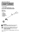
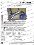
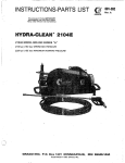
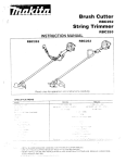
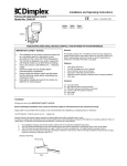
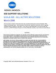
INSTRUCTIONS-PARTS LIST
e
ORACO
307-308
Rev. "6" 9-78
SUPERSEDES 1-78
This manual contains IMPORTANT
W A R N I N G S and INSTRUCTIONS
READ AND RETAIN FOR REFERENCE
HYDRA-CLEAN"1007
MODEL 226-813 SERIES "A"
Includes Hose and Gun Kit and
Chemical Injector Kit for injecting
cleaning chemicals downstream
from pump.
l d w PSI I70 barl OPERATING PRESSURE
1260 PSI (83barl MAXIMUM WORKING PRESSURE
Supplement information referred to
on CAUTION tag has been included
in this manual.
GRACO INC. P.O. BOX 1441 MINNEAPOLIS, MN 55440
@COPYRIGHT 1978 GRACO INC.
W ARNlNG
HIGH PRESSURE SPRAY CAN CAUSE SERIOUS INJURY
READ THESE WARNINGS BEFORE USING
KEEP A W A Y FROM SPRAY
GAS ENGINE PRECAUTIONS
Because of the high pressure and velocity of thespray,
fluids could penetrate the skin, causing serious injury.
Operate equipment only after all instructions are clearly
understood.
NEVER fillfueltankwhileengine
is running or hot.
Avoidthepossibility
of spilledfuelcausinga
fire.
Always refuel slowly t o avoid spillage.
NEVER point the gun at yourself or anyone else. NEVER
put your hand, fingers or body directly over the spray
tip.
Even after you shutoff the gasolineengine, there is high
pressure in the pump. hose and gun until you release it
by triggering the gun.So before removing the spraytip
or servicing the unit, always shutoff the unit and
trigger
the gun to release pressure.
NEVER operate engine in a closed building unless the
exhaust is piped outside. The exhaust contains carbon
monoxide, a poisonous,odorlessand
invisible gas,
which if breathed causesserious illness andpossible
death.
NEVER make adjustments on machinery while it is connected to the engine; first removetheignition
cable
from the spark plug.Turning over the machineryby
hand during adjusting owleaning might start engine
the
and machinery, causing serious injury to the operator.
If thespray appears t o have penetrated the skin.SEEK
EMERGENCY MEDICAL CARE. DONOTTREAT
AS A SIMPLE CUT. Be ready to tell the doctor exactly
NEVER run the engine with governor disconnected, or
operate at speeds in excess of 3300 RPM load.
what fluid was injected.
Besure that all accessory itemsandsystemcomponents will withstand the pressure developed. NEVER
exceed the pressure ratingof any componentin system.
NEVER alter ormodify equipment - yourpersonal
safety, as well as the function of the equipment, is a t
stake.
Before
each
use, check
hose
for weak, worn or
damaged conditions caused by traffic, sharp corners,
all fluid conne,ctions
pinching
or
kinking.
Tighten
securely before each use. Replace any damaged hose.
Do not use chemicals or agents which are compatible
with Buna-N and Buna-N/PVC or neoprenecoverof
hose.
Do not leave a pressurizedunit unattended. Shut off the
unit and release pressure before leaving.
Precaution is the best insurance against an accident.
When starting theengine, maintain asafe distance from
moving parts of the equipment.
GENERAL
NEVER run unit with coupling
shield or pump cover
plate removed. Keepclear of moving parts when unit is
running.
Observe detergent manufacturer's safety precautions.
Avoid getting detergent or other liquids in your eyes.
Follow the directions on the container regarding contact
with eyes, nose, and skin, breathing fumes, etc. Always
wear full goggles to protect your eyes from thespray as
well as any debris dislodged by the spray. If necessary,
wear gloves or other protective clothing. If antidotes or
treatment are recommended, be prepared to use them.
DON'T spray.toxicchemicalssuch
weed killer.
FIRE
as insecticideor
Do not sprayflammable liquids. Do not operatethe
engine wherecombustiblefumes
or dust may be
present.
IMPORTANT
United States Government safety standardshave been adopted under the Occupational Safety and Health Act. These
standards - particularly the General Standards, Part 1910, and the Construction Standards, Part1926 - should be
consulted in connection with your use of airless spray equipment.
307-308
1
SETTING UP UNIT
-A
NOTE:
Reference
numbers
and
letters in parentheses in the text refer to Figures 1,3,
4
and the Parts Drawing.
than 50 ft. (15 m) long. A 25 ft. (7 m) garden hose (1071
is supplied with unit.
NOTE:
Refer to the engine instruction booklet provided with
the unit.
Prepare The Cleaning Solution
Prepare and use cleaning
solution
according
manufacturer's instructions.
For direct
a supply
system,
your
water
source must have a flow rate of ATLEAST
7.5 GPM I28 LITER/MN). If it is less, we
recommend using a siphon hosefrom a supply container.
to
For spraying .detergent or other cleaning solution, we
recommend using a chemical injector kit. See instruction manual 307-325 for installation and operation.
Install Hose and Spray Gun
Assemble the spraygun, extension tube and nozzle
valveandconnect
the spray gun t o the hose. See
manual 307-309 for details.
Connect Siphon Hose
Remove swivel fitting (81) at water'filter manifold 183)
andscrewsiphonhose(104)
into manifold. Squeeze
clamp (105) together and route siphon hosethrough it.
Release clamp and hookit over edge of drumso the top
lip of clamp restson the inside ofdrum and the lower lip
rests against the outside of drum. See Fig 1. The hose
should be between 2-4 inches (50-100 mm) off bottom
of drum.
We recommend installing a float valve (A) on drum to
If a longer spray hose is required, 1/2 in. ID (12 mm)
hose may be added at unit to a maximum overall hose
length of 150 ft. (45 m).
Connect To Water Supply
CAUTION
Beforeattaching to watersupply,checklocal
plumbing
code
regarding
cross-connection
water supply.
to
Do not exceed 150' F (65" Cl water temperature
to pump in a direct supply system.
Connect a hose with a t leasta 3/4 in. (19 mm) ID from
your city water supply to the unit's 3/4 garden hose
threadedinlet.Thesupplyhoseshould
not be more
2 307-308
maintain proper water level. See ACCESSORIES.
We do not recommend installing a shut-offvalve at the
intake as it could cause a pressure drop and cavitationin
the pump. However, if you must have a shut-off valve,
be sure it's inlet and outlet are the samesize as the
hose.
CAUTION
Do not exceed 70' F (28" C) water temperature to
pump in a siphon supply system.
If your operating conditions are different from above,
contact
our
Customer
Service
Department
for
assistance.
~
OPERATION
Startup
Before starting, besure to read the safety warnings and
setup instructions.
Check oil and gasoline levels daily and
grease the pump
if necessary.
Turn on the water supply.
Hydra-Clean Operation
Hold thespray nozzle about 2 feet 10.6 ml from thesurface and completely mist-wet the object with cleaning
solution. Let it soak briefly, then use the spray rinse to
"chisel" the dirt off. Keep the nozzle at an angle to the
surface, and about6 in. 1150 mm) away. Ifsome dirt reit soak a little
mains, repeattheprocedure,letting
longer. When you have finished cleaning, shut off the
unit'and trigger the spray gun to relieve pressure.
Trigger the gun to release any back pressure.
Protect surfacesthat might be
damaged by the cleaning
solution, and rinse before solution dries.
WARNING
DO NOT wire or tie the gun trigger into the open
or triggered position.
Set the choke and openthe fuel valve.
NOTE:
You can clean off stubborn dirt better with a
stronger, heated cleaning solution.
Shutdown and Care Of The Unit
WARNING
CAUTION
You must trigger the gun while starting, to avoid
engine kickback.
Put your foot on the frame or wheel to steady the unit
left
when you pull the starter rope. Hold the gun in your
hand with the trigger open while starting the
engine.
See Fig 2 for the proper stance.Brace the wand as
shown t o avoid recoil.
Grasp the starter rope grip and rapidly pull out the cord
two or three feet I 1 ml. Repeat if necessary with the
chokeopenedslightly.When
the engine starts, immediately release theguntrigger.
Open the choke
gradually.
CAUTION
Never run the cleaning unit dry. Costly damage to
the pump willresult. Always be sure water supply
is completely turned on before operating.
for
any
Inspect all connections
necessary.
leaks. Tighten
if
When unit is not in
use, turn off water
supply.
When shutting down for the day or weekend; shut off
unit, shut off water supply valve, and trigger gun to
release pressure. Wipe off the unit with a damp rag.
Shut off cleaning unit when not actually spraying, for
longer pump life. The pump willoverheat if leftrunning
for over 10 minutes without spraying.
Check the filter screen in the water inlet connection as
often as necessary. Do not operate the unit with the
inlet filter screen removed.
DO NOT try to adjust the unloader valve or change the
engine speed. Changing these settings may cause excessive
pressure,
intermittent unloader
operation,
wasted fuel and increased wear on parts.
PUMP MUST NOT BE RUN DRY and must be drained
of water priort o exposure to freezing temperatures.Use
andstore the unit where it will not besubjected to
freezing temperatures. If water does freeze in the unit,
thaw before trying to start. A 50% anti-freeze solution
may be pumped prior to cold weather storage.
Use only spray tips that are matched to unit to avoid
excessive cycling and wear of the unloader valve. See
ACCESSORIES.
Let a frozen pump thaw in a warm place. Don't
pour hot water ona frozenpump.
A sudden
temperature change greater than 100" F 130' C)
will crack the ceramicC
cylinder liners.
r
A
~~~~~
Do not pump caustic materials.
Before extended storage, flush the pump with light oil.
Observe
oil
change,
gasoline,
and
greasing
requirements as outlinedon page 2 andtheengine
manual.
Avoid dragging hose over an abrasive surface such as
cement. This causes wear and eventual rupturing.
Clean the intake line strainer daily.
307-308
3
Lubrication
Change the engine oil after every
50 hours of operation.
Grease the pump's front bearing and main bearing after
every EO hours of operation. Removeexcessgrease
from the front bearing cavity. Replace the pump front
cover before starting the engine.
Lubricate the gear reduction unit regularly: change the
oil every 500 hours, but sooner if oil becomes dirty; The
engine manufacturer recommends using "For Service
SD or S E ' S.A.E.30 oil for spring,summer, orfall
operation, and S.A.E. 20 for winter operation.
Drain oil with engine warm. Place pan under reduction
unit and loosen cover.
NOTE:
Oncea
year, removeenginecover
completely and flush out inside of housing with
kerosene. DO NOT use gasoline for
cleaning.
unit and add oil if necessary to maintain proper level.
NOTE:
Vented
filler
plug
should
be
removed
periodically
and
vent
hole
thoroughly
cleaned. Ventilationis necessaryto eliminate
pressurebuild-upcausingoil
leaks, and to
preventcondensation from forming in the
housing.
Followthe maintenanceprocedures forthe
outlined in the accompanymg instructions.
engine
The accumulator (EO) which acts as a buffer to smooth
pump strokes, isnitrogen. chargedandmust
be recharged generally every 6 t o 12 months t o 540-660psi
(37-45bar).Contactalocal
fire extinguisherservlce
location for recharging.
Remove filler andlevel plugs. Pour oilthrough vent hole
of filler plug until it runs out through level hole. About
3/8 pint ( 1 7 7 cc) is required. Replace oil level plug and
vented filler plug.
Never remove stem valve from accumulator, or
check its pressure wlth a standard tire pressure
Never try to recharge accumulator with ordinary
car service station equipment.
When changing engine crankcase oil, check reduction
TROUBLESHOOTING
Engine Will Not Start
Or Hard To Start
No gasoline in fuel tank or
carburetor.
Fill the tankwith gasoline, open fuel shut-off valve.
Check fuel line and carburetor.
Water in gasoline or old fuel.
Drain fuel tank and carburetor. Use new fuel and
dry spark plug.
Choked improperly. Flooded
engine.
Push in choke,open throttle control and
engine several times to clear out the gas.
crank
Dirty carburetor air filter.
Remove and clean.
I
Engine Misses Or Lacks
Power
I
Excessive
Machine
Worn
shaft
Vibration
Excessive Vibration Of
Hose
Spark plug dirty or improper
gap.
Clean, adjust the gap or replace.
Spray valve closed.
Open valve.
Partially plugged air cleaner.
Remove and clean.
Low oil level or dirty oil.
Check or change oil.
Spark plug dirty, wrong gap,
or wrong type.
Clean, adjust the gap, or replace.
Incorrect ignition timing.
.
Time engine.
couplers.
Loss of dampener charge.
Damaged pulsation dampener
bladder.
Decrease Delivery
Accompanied By Rough
Operation
Air entering suction piping;
Air leaking past piston cups;
Pump valve malfunction:
Plugged or restricted pump
suction passages:
4
307-308
Replace couplers or coupler insert.
Recharge with approximately 540-660 psi'(3745 bar) of nitrogen.
Replace accumulator.
Examine the valveseats
Replace if necessary.
for wearandpitting.
to collectdischarged
Arrange a barrelortank
water from pump. Compare this tothe rated
has actually
capacity to see ifthedischarge
decreased.
Plugged or constricted
suction piping (suction valve
not fully open);
Collapsed suction hose.
Examine the water in the barrel or tank for air
bubbles whilethepumpis
discharging. Ifno
bubbles are seen and the discharge has actually
decreased, look for plug-ups, worn valve seats, or
collapsed suction hose. If bubbles are seen, look
for air leaks in the suction piping or forair leaking
past the piston cups. These leaks are hard to find
because they are leaking "in" rather than "out".
However,
arrangements
if
are made to put
pressure into the suction piping or if new cups
smooth out the pump operation, the problem is
solved
Decreased Delivery
Accompanied By Smooth
Operation
Worn valve seats.
Lookfor worn or pitted valveseats.
necessary.
Replace if
Slipping couplers.
Measure
clearance
between
outer
surface
or
eccentric roller bearingandyokepads
with a
feeler gauge. This should not exceed 0.010 inch
(0.2% mm).
NOTE:
Excessive Leakage
Worn piston cups;
Loose piston bolts;
Worn yokepads will give a verynoisy
operation. Replace the yoke or pads if
necessary.
Examine pistons and cups for wear. Generally a
cup will not leak severelyuntil it is torn.The piston
should not be more than0.020in. 10.508 mm) out
of round.
Damaged O-rings;
Cracked ceramic liners;
Tighten loose piston bolts, cylinder headbolts and
valvecaps. Remove head and sand flat part on
80-grit sandpaper which is laid on a flat surface.
Faulty gaskets;
CheckO-rings
andgaskets for wear orbreaks.
Loose valve caps;
Loose cylinder head bolts or
malfitted heads.
Remove cylinder heads andblocks to examine
ceramic liners for cracks. Replace all damaged
parts.
SERVICE
Pistons and Yoke
Take off the cylinder head (14) by removing four112 in.
socket head capscrews
(A). See Fig 3.
Use a 7/32 in. socket wrenchto unscrew the piston bolt
(13) from the yoke. Slide out the cylinder liner (21) and
piston assembly. Leave the yoke in place.
Examine the ceramiccylinder
liner (21)forcracks.tight
Replace worn or cracked parts before reassembling
into
pump body.
NOTE:
Assembleallpistonparts (10. 11. 12. 13,21, 22, 2
3, 24)
as shown and push theassembly into the. cylinder liner.
Make sure that
the
O-ring is in the recess of the
piston
cap.
'
Screw the piston bolt into the
yoke. The bolt has a
countersunk head capscrew of the lockwell type and
will require a-little extra effort to turn. Makecertain it is
to prevent leakage throughthe b.olt hole.
Repeat the procedurefor the opposite
side of the pump.
Dirty grease sludgeadhering to thewallof
thecylinder liner shouldberemoved with
emery cloth before the
liner is replacedin the
pump body.
307-308
5
'
Valve Replacement ..
Mount the valve disc (61 on the spring (7). See Fig 3.
Then mount the spring in the cage recess (8). Slip thls
assembly into thehead cavities behindthe valve seat (5)
and O-rings (4). Put the valve caps 115) over these and
install bolts (161.
Make sure that the O-rings (2 & 3)have been insertedin
the proper places accordingto thediagram. It is Wise to
grease the headO-rings to prevent them from fallingOut
during assembly.
Bolting Cylinder Head AssemblyTo Pump Body
install the cylinder (14) head right side up on the pump
body, as shown.
17-
9"
'*Repair Kit P a m
Fig 3
6
307-308
Unloader
Remove the locknut (67). adjusting nut ( 6 8 ) and spring
washers (71).
d. The unit should "unload" at 1050 t o 1150 psi (7279 bar) water pressure.Close the spray valve and
note pressure. Continueadjusting the nut,closing
the spray valve, and checking pressure until required
pressure is obtained. Tighten the locknut. Check the
unloading pressure a couple more times
by triggering
the gun and noting pressure.
e. Shut off the unit, trigger gun to,relieve pressure,
remove the gauge and replace the pipe plug.
Remove bolts (511 and separate the upper and lower
casings (48 and 49). All other parts can then be freely
removed.
To replace the cup and back-up ring (46 and 47):
a. Cut through the old cup
and back-up ring and
remove them from the valve stem.
b. Grip the shaft sleeve (69) in a vise equipped with jaw
protectors.
c. Slowly heat the end of the valve stem and
piston 165)
with a propanetorch. Whenthe assembly ishot
enough, (about 250" F [120" C]) the piston can be
easily screwed off the valve stem by firmly gripping
with a pair of pliers.
d. After the assembly cools, mount a new back-up ring
and cup on the piston.
e. Beforereplacing the piston, put a few dropsof
locking compound on the valve stem threads.
NOTE:
Increasing valve unloaderpressurebeyond
specified
setting
will
not
increase tlp
pressure or flow rate.
be
Items 69 and 70 are supplied as a unit and should not
disassembled.
Assemble in reverse order withthefollowing
cautions:
pre-
a. Be certain the by-passvalve seat ( 5 8 ) is installedwith
the flat side of the valve against the valve ball (60).
b. The first spring washer (71) is installed concave side
downward and the remaining springs are alternated
as shown. See Fig 4.
'
Never shim or alter the 17 spring washers 171) as
thiswill cause theunitto
overpressurize and
damaae
I
Citself. A
U
T
'
O
N
~~
. ...
..
1
~
To readjust the pressure of the unloader valve:
a. Replace the 1/4 in. pipeplug (102) in theoutlet
manifold (101) with a 1500 psi (103 bar) min. pressure
gauge.
b. Screw the adjusting nut ( 6 8 ) into the stem (69) until
approximately 118 in. of thread is exposed.
c. Start the unit according tooperation instructions on
page 2.
"Repair
Kit Parts
52
51
307-308
7
MODEL 226-813 SERIES "A"
WITH HOSE, GUN AND NOZZLE
Includes items 1-102
8
307-308
PARTS LIST
REF PART
NO.
NO.
1
2
3
4
5
6
7
8
9
10
11
12
13
14
15
16
17
18
19
20
21
22
,
23
24
25
26
27
28
29
30
31
32
33
34
35
36
37
38
39
40
41
42
43
44
45
46
47
48
49
50
51
52
53
54
an
DESCRIPTION
*104-868 PUMP ASSY
Includes items 2-36
. PACKING, O-ring
ff
. PACKING,O-ring
x*
. PACKING,O-ring
*I
. SEAT,valve
f.
. DISC,valve;ceramic
**
. SPRING, valve; tapered
compression
**
.
CAGE, valve
**
.
PACKING,O-ring
**
.
PISTON, phenolic
**
. CUP, piston
**
. PACKING,O-ring
. BOLT,piston
105-304 . CYLINDER HEAD
105-301 . CAP, valve
100.659 . CAP SCREW, socket head
. HOUSING, pump
. YOKE
. PAD, yoke
. COVER
'104-870 . LINER, cylinder; ceramic
. SPACER, piston
.WASHER, packing
. CAP, piston
. .
. LOCKNUT
. LOCKWASHER
. SPACER, outer bearing
. SEAL, bearing
. BEARING; tapered roller
. RACE,bearing
. SPACER, inner bearing
. CRANKSHAFT
. BEARING, eccentric
.WASHER, retainer
. LOCKWASHER, spring; 3/8
. CAPSCREW
'104-862 COUPLER
'104-861 INSERT, coupler
ENGINE, gasoline; 7.5 hp
"104-853 UNLOADER ASSY.
Includes items 41-72
fl
. PACKING, O-ring
.f
. PACKING, O-ring
*.
. WASHER, shaft
. LIMIT,O-ring
.
I
. PACKING,shaft
.*
. CUP
X"
. BACKUP
. HOUSING,upper
. HOUSING, lower
. PACKING, O-ring
. CAPSCREW,hex hd
. LOCKWASHER, spring
. SEAL, inlet valve
. VALVE, inlet
*.
REPAIR KITS
PISTON KIT 104-856
Includes items 10, 11, 12.
. SPRING,compression
. RETAINER, valve spring
. SEAT,valve
. PACKING,O-ring
. BALL, check valve
. SPRING,compression
. CYLINDER
. SLEEVE, limiting
. WASHER
. PISTON
. STEM,valve
. LOCKNUT
. NUT, adjusting
. SLEEVE,shaft
. WASHER
56
*X
1
57
4
2
4
4
4
58
59
60
4
4
4
2
2
2
4
2
2
8
1
1
2
1
4
4
4
4
1
1
1
2
2
2
1
1
in
61
62
63
64
65
66
67
68
69
70
71
72
73
74
76
78
79
80
81
82
83
84
85
86
87
88
89
1
91
92
93
94
95
1
96
1
97
1
1
1
1
1
1
1
1
1
1
1
2
1
1
1
1
1
1
1
. WASHER, spring
17
.WASHER
214-728 HOSE Et GUN KIT,
See 307-309 for parts
WHEEL, semi-pneumatic
'174.063
104-811 CAP, hub
104-871 COUPLER, female
104-872 COUPLER,male
* 104-869 ACCUMULATOR
UNION, straight swivel
104-863 WATER FILTER ASSY.
Includes items E3-86
105305 . MANIFOLD, filter
104-864 . GASKET,rubber
'104-865 . SCREEN, filter; 80 mesh
'105330 . BOWL, filter
NIPPLE, pipe; 3/4 npt
TEE, pipe: 3/4 npt
104-866 HOSE
105306 HANDLE
PLATE
BRACKET
"104-860 CREEPER
1
1
2
2
1
1
1
1
1
1
1
1
1
1
1
1
1
1
1
2
BOLT
~~
98
1
1
2
2
99
101
103
214828
1
1
104
215-427
1
1
1
1
105
106
107
176-741
176-724
105-435
1
108
104-867
4
4
1
1
aN
DESCRIPTION
REF PART
NO.
NO.,
d
AXLE
PIN, cotter
GUARD, couper
BRACKET, pump
MANIFOLD ASSY
SPRAYER
AS&
.~
SPRAYER
ASSY.
Includes items 1-72, 75101
HOSE, siphon; 1-1/4 in. ID
6 ft. 11.8ml lg
CLAMP,hose
TAG, caution
HOSE, garden, 3/4 in. thread
25 f t . 17 m) Ig
CHEMICAL INJECTOR KIT
See 307-325 for Darts
1
2
1
2
1
1
1
1
1
1
306 & 307 Numbers in description refer to separate instruction
manuals.
Wecommended 'tool box" spare parts. Keep on hand io
reduce down time.
VALVE KIT 104-855
"Supplied in repair kit. (Kit must be purchased separatelyl.
Includes items 2-9.
Order parts by name and number. Always give ihe model
number and series letter of the assembly for which you are
ordering.
UNLOADER VALVE KIT 104-854
Includes items 41-47.
307-308
9
~
ACCESSORIES (Must be purchased separately)
STAINLESS STEEL TIPS
SPRAY HOSES
Additional hoses may be used up to a maximum
overall length of 150 f t 146 m) overall length. Purchase
part no, 207-152 swivel union to connect hoses.
Fan Width
Part No.
160-968
Thd
Length
Part No.
Size
160-956'
Imbel
19.5 mml
1/2 in.
113 mml
3/8 npt
Imbel
0.109 1520
0.109
160-962
2520
3/8 npt
205-EO9
Number
Orifice
Angle
at
tip
on
size
L
4020
40 psi 13barl
in.
12.77 mml
in.
12.77 mml
0.109 in.
12.77 mm)
15"
25"
40"
"Tip available on special order.
HOSE 8 GUN KIT 214-728
CHECK VALVE 103-913
Prevents back up of contaminated water into fresh
supply. Install upstream from pump.
Same as hose and gun supplied with unit.
FLOAT VALVE 205-971
Automatic shut-off valve prevents overfilling siphon
supply drum.
STAINLESS STEEL BLASING TIP 102-488
0.107 in. (2.72 rnm) orifice.
THE GRACO WARRANTY
TECHNICAL DATA
ENGINE: WISCONSIN ROBIN.MODEL
EY27W 4 cycle, single cylinder,
air cooled, 7.5 hp
GASOLINE TANK: 1.45 gallon capacity
WATERPUMP:12WPSI
1 8 3 bar) max.pressure:
7 GPM 127 liter/minl at loo0 PSI
I70 bad.
WETTED PARTS: Stainless
Steel, Aluminum. Phenolic
Plastic, Ceramic Linen, Nitrile
Rubber.
WEIGHT 170Ib 175 kg) (not including
gasoline and motor oil).
OVERALL DIMENSIONS: Length: 50" 11.3.ml
Width: 22" 1560 mml
Height: 2 4 1610 mml
MAX, WATERTEMPERATURE:
150" F 165" C)
iNLET HOSE CONNECTION: 3/4" garden hose If1
Graco Inc. warrants all equipment manufactured by it and bearing its
name to be free from defects in material and workmanship under
normal use and setvice. This warranty extends tothe original
purchaser for a period of 12 months from the date of purchase and
applies only when the equipment is installed and operated in
accordance withwrittenfactory
recommendations. This warranty
does not cover damage or wear which, In the reasonable judgment of
Graco. arises from misuse, abrasion. corrosion, negligence. accident,
substitution of "on-Graco pats, faulty installation or tampering.
This warranty is conditioned upon the prepaid return of the equipment
claimed to be defective for examination by Graco to verify the claimed
defect. If the claimed defect is verified. Graco will repair or replace
free of charge, any defective parts. The equipment will be returned to
the original purchaser transportation prepaid. If inspection of the
equipment does not disclose any defect in workmanship or material.
repairs will be made at a reasonable charge and return transportation
will be charged.
THIS LIMITED WARRANTY IS EXCLUSIVE, AN0 IS IN LIEUOF
ANYOTHER WARRANTIES (EXPRESS OR IMPLIED) INCLUDING
WARRANTY OF MERCHANTABILITY OR WARRANTY OF
FITNESS FOR A PARTICULARPURPOSE AND OF ANY NONCONTRACTUAL LIABILITIES INCLUDING PRODUCT LIABILITIES
BASED ON NEGLIGENCE OR STRICT LIABILITY. EVERY FORM OF
LIABILITY FOR DIRECT, SPECIAL OR CONSEQUENTIAL
DAMAGES OR LOSS IS EXPRESSLY EXCLUDED AND DENIED.
EQUIPMENT NOT COVERED BY GRACO WARRANTY. Accessories
or components of equipment sold by Gracothat are not manufactured
by Graco lsuch as electric motors. switches. hose, etc.1 are subject to
the warranty. if any. of their manufacturer. Graco will provide
purchaser with reasonable assistance in making such claims.
Factory Branches: Atlanta. Cleveland. Dallas, Detroit ISouthfieldl. 10s Angelss. Vlest Caldwell IN.J.1
Subsidiary and Affiliate Companies: Canada: England: Switzerland: France: Germany:
Hang Kong: Japan
GRACO INC.
P.O. BOX 1441
MINNEAPOLIS, MN 55440
PRINTED IN U.S.A. 307~3081 78 Revised 9 78