1
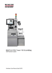
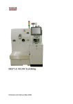
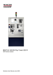
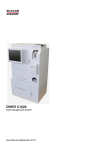
BEETLE /iSCAN Tower Line 100
Important Notes, Site Preparation and Commissioning (May 2009)
We would like to know
your opinion on this publication.
Please send us a copy of this page
if you have any constructive criticism on:
- the contents
- the layout
- the product.
We would like to thank you in advance
for your comments.
With kind regards,
Wincor Nixdorf International GmbH
RD PD1
Rohrdamm 7
Haus 16
D-13629 Berlin
Fax: +49 30 5017 1075
__________________________________________________________________________________________________
Your opinion
All product names mentioned in this document are registered trademarks.
Copyright © Wincor Nixdorf International GmbH, 2009
All rights including the rights to the translation, reprinting, transmission or copying by any means, in whole or in part, are
reserved. Offenders will be liable for damages. All rights including rights resulting from a patent grant or registration of a utility
or design are reserved.
Contents
Introduction .............................................................................................................................................. 1
About this manual ................................................................................................................................ 1
Warranty .................................................................................................................................................. 2
Important Notes ....................................................................................................................................... 3
Note on Laser ...................................................................................................................................... 5
Tools you need ........................................................................................................................................ 6
Customer Requirements.......................................................................................................................... 7
Components ............................................................................................................................................ 8
Components Inside .............................................................................................................................. 9
Rotating the top module of POS Tower (optional) ................................................................................ 12
Maintenance ...................................................................................................................................... 13
Unpacking and checking the System .................................................................................................... 14
Installing the Device in the Store ........................................................................................................... 15
Removing the Transportation Locks...................................................................................................... 17
Scanner (Scale) ................................................................................................................................. 17
Pole Light ........................................................................................................................................... 17
Cash Media Dispenser....................................................................................................................... 18
Display and Notebox.......................................................................................................................... 20
Security Scale .................................................................................................................................... 22
Accessories in the Safe ......................................................................................................................... 23
Removing the Foils................................................................................................................................ 23
Connecting the Keyboard ...................................................................................................................... 24
Connecting the System (Rubber Connector 240V)............................................................................... 26
Start up............................................................................................................................................... 26
Main Power Switch......................................................................................................................... 29
Connecting the System (Twist Lock - 120V and USV).......................................................................... 30
Start up............................................................................................................................................... 30
Main Power Switch ............................................................................................................................ 34
Shutdown............................................................................................................................................... 34
LAN Connection .................................................................................................................................... 35
Three Bags Module ............................................................................................................................... 38
Keys for the three Bags Module ........................................................................................................ 38
Installing the Three Bags Module ...................................................................................................... 39
Adjusting the Security Scale Module.............................................................................................. 41
Cabling of the three bags module...................................................................................................... 42
UPS ................................................................................................................................................ 43
Security Scale ................................................................................................................................ 44
Basket Tray ........................................................................................................................................... 45
Baseboards ........................................................................................................................................... 45
Appendix................................................................................................................................................ 46
Further Documentation ...................................................................................................................... 46
Cleaning Instructions ......................................................................................................................... 46
Maintenance and Service............................................................................................................... 46
Maintenance for the rotating top module........................................................................................ 46
Approved Cleaning Materials ......................................................................................................... 47
Changing the Safe Code (LG 39E).................................................................................................... 48
Generally ........................................................................................................................................ 49
Programming Manager................................................................................................................... 53
Programming on PC....................................................................................................................... 57
Manual programming ..................................................................................................................... 59
BEETLE /iSCAN Tower Line 100 – Dimensions ............................................................................... 61
Block Diagram.................................................................................................................................... 63
Environmental Requirements ............................................................................................................ 64
Certifications of the manufacturer ......................................................................................................... 65
Note on Radio Interference Suppression........................................................................................... 65
FCC-Class A Declaration................................................................................................................... 65
Recycling the BEETLE /iSCAN Tower Line 100................................................................................ 66
Important Notes, Site Preparation and Commissioning
Introduction
The BEETLE /iSCAN Tower Line 100 is a terminal where the user handles the purchase by scanning,
bagging and paying the items on his own. In case of problems an attendant is available for quick support.
The BEETLE /iSCAN Tower Line 100 is connected to an attendant station. This is a POS system controlling all connected BEETLE /iSCAN POS Tower 100 terminals.
BEETLE /iSCAN Tower Line 100 offers the following main functions:
Record function - records items, the customer wants to buy
Control function - secures the recording of all items
Payment function - payment may be effected by banking cards, customer cards and accounts,
coupons, bank notes or coins. Cash return uses bank notes and coins.
About this manual
This manual refers to technically trained personnel only.
It provides all necessary site preparation information for installing BEETLE /iSCAN Tower Line 100 at
your site.
Notes are marked by this symbol.
Caution! Identifies action requiring caution.
The responsibility for all technical and special prerequisites for installation of BEETLE /iSCAN Tower
Line 100 is borne by the customer. A detailed list of customer responsibilities is given in this manual.
Installation as well as connection of BEETLE /iSCAN Tower Line 100 may only be executed by technically trained personnel.
The safety instructions given in this document should be strictly followed when handling
BEETLE /iSCAN Tower Line 100. Further safety, installation, and maintenance instructions can be
found in the manuals supplied with the components.
In case of doubts or questions please contact Wincor Nixdorf International (WN).
1
Important Notes, Site Preparation and Commissioning
Warranty
Wincor Nixdorf guarantees generally a warranty engagement for 12 months beginning with the date of
delivery. This warranty engagement covers all damages which occur despite a normal use of the
product.
Damages because of
improper or insufficient maintenance,
improper use of the product or unauthorized modifications of the product,
inadequate location or surroundings
will not be cover ed by the warranty.
For further information on the stipulation consult your contract.
All parts of the product which are subject to wear and tear are not included in the warranty engagement. For detailed warranty arrangements please consult your contract documents.
2
Important Notes, Site Preparation and Commissioning
Important Notes
Appliances supplied by Wincor Nixdorf International GmbH comply with the respective safety regulations for data-processing installations and information technology installations, including electrical
office equipment for use within an office environment.
Switch off the device at the main power switch.
If UPS is installed, you must switch off this too, to separate BEETLE /iSCAN Tower Line 100
from power completely.
Appliances may only be repaired by authorized technicians.
Unauthorized opening of the housing or inexpert repairs can result not only in considerable
personal danger, but will also invalidate your warranty and liability protection.
Always consult the enclosed documentation before doing any work with this appliance.
If this device is brought from a cold environment into a heated place of business, condensation may occur. Before operation, the device must be completely dry. Therefore, an acclimatization period of at least two hours must be adhered to.
Always lay the supply leads and cables in such a way that they cannot be stepped on or
tripped over.
Exchange damaged cables immediately.
In order to completely disconnect the device from the power source, turn the device off and
use the separator in the fuse box\building installation.
Make sure that no objects (such as paper clips) can reach the interior of the device, since
electrical shocks or short-circuits could result.
To avoid overheating of the power supply unit. Ensure that the BEETLE /iSCAN Tower Line
100 receives adequate ventilation. ->
Ensure that the BEETLE /iSCAN Tower Line 100 receives adequate ventilation to avoid overheating.
During an electrical storm, data cables should not be plugged in or unplugged.
Keep the device away from vibrations, dust, humidity, and heat.
Ensure that used parts are disposed of in an environmentally friendly manner.
In case of an accident (such as a damaged housing, entry of liquids or foreign objects), switch
the device off and use the separator to completely remove the device from power..
The BEETLE /iSCAN Tower Line 100 is the result of state-of-the-art technology. Therefore,
please also ensure that the BEETLE /iSCAN Tower Line 100 is operated under modern building and technical conditions in order to ensure flawless and efficient operation. The appliance
and other information technology hardware should only be connected to electrical supply networks with a separate protective earth wire (PE). This type of electrical supply network is referred to as a TN-S network. Do not use PEN conductors. Also follow the recommendations
set forth in DIN VDE 0100 Part 540, Appendix C2 as well as EN50174-2, §5.4.3. This will help
prevent malfunctions.
When working on the cutter of the printer, the device must be turned off.
3
Important Notes, Site Preparation and Commissioning
Always keep the ventilation slots free of obstruction to ensure adequate air circulation and
avoid overheating.
Transport the appliance only in its original packaging (to protect against knocks and bumps).
If a lithium battery is supplied with the appliance, ensure that the battery is replaced with an
equivalent type. Otherwise there is danger of explosion! Lithium batteries may only be replaced with identical types or other types recommended by the manufacturer.
Batteries must be disposed of according to local regulations on the disposal of special waste.
Connecting Peripherals
Use only shielded cables when connecting devices to the system to ensure compliance with
international Rules and Regulations for radiated emission as well as to achieve a high immunity against external disturbances.
Coin Module
The coin dispenser is a safe product. All the necessary precautions have been taken to ensure that normal operations and maintenance procedures are safe.
Care should be taken to keep fingers clear of the hinged chassis panels when dumping coins
or rotating the hoppers to gain access to the inside of the unit. This area is a potential pinch
hazard and may cause significant injury when using hoppers filled with coin.
Wincor Nixdorf International will not be held liable for damages and/or personal injuries
brought on by incorrect operation and maintenance practices.
Only a qualified service technician should replace an individual hopper assembly or remove
the pcb protective shield to access internal components. Ignoring this warning may void the
products warranty.
Safety Icons
E
Critrical Shock Hazards - indicates potentially lethal voltages are present.
Stop! - Identifies important information requiring special attention.
Caution! - Identifies actions requiring caution.
.
4
Pinch Hazard - identifies possible pinch hazards
Important Notes, Site Preparation and Commissioning
Heavy Objects
Caution: The coin dispenser weighs approximately 21 pounds unfilled with coin. When transporting the unit, avoid bumping or dropping it, which could damage the unit. The coin dispenser should be empty of coin before transporting. If dropped on a body part, the coin dispenser could cause serious personal injury.
Caution: The coin dispenser weighs approximately 65 pounds filled with coin. Do not move
filled. Mounting supports should be properly designed to handle the load.
Caution: The coin dispenser should be secured to a sturdy, flat surface before utilizing its
hinged chassis to dump and empty a hopper of coin.
Cleaning Instructions
Always turn off the system before cleaning.
specials:
If liquids were spilled over your System switch off the system and disconnect the power plug.
Dry the device with a cloth and leave it switched off for a while.
LCD-Displays
If the display element is damaged and the liquid crystal solution leaks out onto your hands or
clothing, please wash your hands or clothing immediately under running water for at least 15
minutes, using soap or alcohol. If the liquid comes into contact with your eyes, consult a medical doctor immediately.
Inside the display, the high voltage needed for backlighting the LCD display is generated by
the inverter! High Voltage!
Before opening the device, make sure, that the device is disconnected from the main power
supply. Opening of the device only by authorized personnel!
Note on Laser
The PSC 82xx and 8300 Scanner/Scale is not intended for long-term viewing of direct laser light. However, the unit is safe if used as intended.
This scanner meets the following laser/LED power requirements.
Class IIa Laser—Avoid long-term viewing of direct laser light
Class 1 EN60-825 (European Standard)
5
Important Notes, Site Preparation and Commissioning
Tools you need
Keep the following tools at hand for working on the BEETLE /iSCAN Tower Line 100:
Socket wrench
5 mm
Open-end wrench
5.5 mm
Water level
Torx-screwdriver
6 mm, 7 mm, 8 mm and 10 mm
Flathead screwdrivers
(two sizes)
e.g. 1.0 x 6
0.6 x 4.5
Phillips screwdrivers
PHO, 1 and 2
Flathead screw driver
0,5 x 35 mm
Torx screwdrivers (hexagon round screwdrivers)
8, 10 and 20
Antistatic kit
6
Important Notes, Site Preparation and Commissioning
Customer Requirements
Before BEETLE /iSCAN Tower Line 100 installation can be started, the customer is held responsible
to provide the following:
Appropriate drawings concerning location of the equipment as well as site wiring (power and
communications, paths and lengths). Location of other equipment that may generate electrical
noise, electromagnetic interference, or heat
Provision and installation of all communication cables wall jacks, special connectors, and associated hardware
Provision and installation of necessary power distribution boxes, conduits, grounds, lightning
protection devices, and associated hardware
Ensure that all applicable codes, regulations, and laws (including, but not limited to, electrical,
building, safety, and health) are adhered to
Provision and installation of auxiliary power or other equipment as required
Provision of storage or service as required
Provision of a level floor to locate the BEETLE /iSCAN Tower Line 100.
Provision and installation of floor coverings and environmental systems that limit or control
static electricity build-up and discharge
Provision of appropriate equipment for the remote support
The customer is responsible for relocating the Self-Checkout equipment (check stand and components) to the final placement/installation position.
Keep the Wincor Nixdorf equipment area free from dust, smoke, lint, and other particles. Restrict
smoking, eating, and drinking around the equipment. Avoid locating the equipment near other
machines that generate ink, carbon, and paper dust particles.
Please note that Wincor Nixdorf will not take over any warranty/liability if the technical and
environmental requirements are not met.
7
Important Notes, Site Preparation and Commissioning
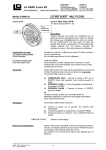
Components
11
10
9
1
15*
8
2
5
7
14
6
3
13
4
12
16
1
Screen
5
Waiters Lock
9
Coin In
13
Hardtag Detector
2
Receipt
6
Coupon In
10
Note In
14
Bag Holders
3
Scanner / Scale
7
Coin Out
11
Pole Light
15
Pin Pad*
4
Note Output
8
MSR
12
Security Scale
16
UPS
*The Pin Pad is customer specific, different models and positions are possible
8
Important Notes, Site Preparation and Commissioning
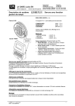
Components Inside
On one side of the BEETLE /iSCAN Tower Line 100 you find the lock for the front door. Put the key
into the lock, turn it to the right and swing the door upwards.
Have a look on the components on the next page.
9
Important Notes, Site Preparation and Commissioning
1
4
7
2
6
5
3
10
1
Coin Dispenser
5
Coupon Box
2
Printer
6
Coin Box
3
Scanner Scale
7
Note Box
4
Coin Recognition
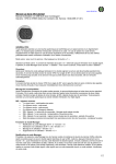
Important Notes, Site Preparation and Commissioning
Behind the bottom door you find the Media Cash Dispenser (1), the CMD Shutter (2) and the central
power supply unit in the back of the safe (3).
2
1
3
Safe cover door
11
Important Notes, Site Preparation and Commissioning
Rotating the top module of POS Tower (optional)
You can rotate the top module of the BEETLE /iSCAN Tower Line 100 including scanner, printer, coin
dispenser etc. by 180°.
Therefore, insert the key into the lock (see arrow) and unlock it.
12
Important Notes, Site Preparation and Commissioning
Durn the bag holders (1) down.
Now rotate the top module by 180° using both hands!
2
1
Maintenance
Clean the rotating surface for the top module after 500 rotations or at least once a year. Clean it with
commercially available soft cleaner.
Dry rotating surface after cleaning!
13
Important Notes, Site Preparation and Commissioning
Unpacking and checking the System
Unpack the system and verify that the scope of delivery is identical to the information on the delivery
ticket.
Should you notice any
transport damages or
discrepancies between package contents and delivery ticket or
functional defects,
please inform your contracting parties or the branch office of Wincor Nixdorf immediately. Please indicate the number of your delivery ticket and delivery ticket position and serial number of the respective
device.
It is absolutely necessary to check the function of the original equipment before you perform
any changes (e.g. by installing an expansion card). Only then is it possible to accept a
functional defect as a claim.
We recommend saving the original packaging for transport at a later time (protection from
impact and shock).
14
Important Notes, Site Preparation and Commissioning
Installing the Device in the Store
The BEETLE /iSCAN Tower Line 100 will be delivered on a pallet with industry standard 1000mm x
1200mm size.
Remove the wrapping paper first. Aside the BEETLE /iSCAN Tower Line 100 you find the ramp to
remove the device from the pallet.
The ramp has to be ordered separately (No. 0175 0128351). The size of the ramp is 600 x
1200 x 118 mm.
Ramp
15
Important Notes, Site Preparation and Commissioning
Put the pallet to the floor in front of the pallet with the device like shown in the picture.
Roll the BEETLE /iSCAN Tower Line 100 down and place it in the store.
The back panel is removable. Leave 1m free area for service purposes.
16
Important Notes, Site Preparation and Commissioning
Removing the Transportation Locks
After unwrapping the system, remove the transportation locks from the following components
(see arrows).
Scanner (Scale)
Pole Light
17
Important Notes, Site Preparation and Commissioning
Cash Media Dispenser
Insert the key into the lock, turn it to the right and open the bottom door of the BEETLE /iSCAN Tower
Line 100.
18
Important Notes, Site Preparation and Commissioning
Now enter the code number of the safe in the data field (1), turn the knob (2) to the right and open the
door.
2
1
Remove the transportation locks.
19
Important Notes, Site Preparation and Commissioning
Display and Notebox
On one the side of the BEETLE /iSCAN Tower Line 100 you find the lock for the front door (see arrow
below). Put the key into the lock, turn it to the right and swing the door upwards.
20
Important Notes, Site Preparation and Commissioning
Remove the transportation locks from the display.
Remove the transportation locks from the notebox.
21
Important Notes, Site Preparation and Commissioning
Security Scale
22
Important Notes, Site Preparation and Commissioning
Accessories in the Safe
Do not throw away the wrapped accessories in the safe. They are necessary to unmount the
cash media dispenser. Find further information in the service manual.
Removing the Foils
Remove foils from hardware components carefully! Let a second person give you a hand, this
reduces the danger of scratches!
23
Important Notes, Site Preparation and Commissioning
Connecting the Keyboard
Unlock the front door and swing it up.
Plug the USB connector to an USB socket at the BEETLE /M-II (1).
1
24
Important Notes, Site Preparation and Commissioning
Only guide the cable as shown in the picture.
Now you can close the front door.
25
Important Notes, Site Preparation and Commissioning
Connecting the System (Rubber Connector 240V)
The delivered system is ready configured. There are just a few things to do, before starting up the
BEETLE /iSCAN Tower Line 100.
Start up
Insert the key into the lock, turn it to the right and open the bottom door of the BEETLE /iSCAN Tower
Line 100.
26
Important Notes, Site Preparation and Commissioning
Now enter the code number of the safe in the data field (1), turn the knob (2) to the right and open the
door.
2
1
Remove the cover of the recess for the mains cable. It is fixed with five screws.
27
Important Notes, Site Preparation and Commissioning
Guide the cable from outside through the recess.
Plug the rubber connector into the power box beside the cash media dispenser (1)) and push the
power button in the position 1 (2).
1
2
Start the system with the main power switch (see next page).
28
Important Notes, Site Preparation and Commissioning
Main Power Switch
On the left side or at the back of the BEETLE /iSCAN Tower Line 100 you find the main power switch.
Open the lock and remove it.
Lock for the safe
See the main power switch now.
29
Important Notes, Site Preparation and Commissioning
Connecting the System (Twist Lock - 120V and USV)
The delivered system is ready configured. There are just a few things to do, before starting up the
BEETLE /iSCAN Tower Line 100.
Start up
The power supply system must be equipped with separately guided protective earth conductor (PE).
This kind of electricity system is known as TN-S network. Do not use PEN conductors!
An overload and short circuit protection is not part of the BEETLE /iSCAN Tower Line 100.
A 16A fuse complying with IEC60127 (breaking capacity of 1500A) must be part of the
building installation.
High leakage current! Earth connection essential before connecting supply!
In the housing you find a Twist Lock plug for the connection to the house installation. Do never use
rubber connector for the house installation.
House Installation
30
Important Notes, Site Preparation and Commissioning
Insert the key into the lock, turn it to the right and open the bottom door of the BEETLE /iSCAN Tower
Line 100.
31
Important Notes, Site Preparation and Commissioning
Now enter the code number of the safe in the data field (1), turn the knob (2) to the right and open the
door.
2
1
Plug the rubber connector into the power box beside the cash media dispenser (1) and push the
power button in the position 1 (2).
1
2
32
Important Notes, Site Preparation and Commissioning
Remove the cover of the recess for the mains cable. It is fixed with five screws.
Switch off the power from the house installation!
Guide the cable from the safe through the recess, mount the Twist Lock coupler to the power cable
and plug it into the house installation socket.
Switch on the house installation and start the system with the main power switch (see next page). Do
not forget to switch on the UPS, if installed.
33
Important Notes, Site Preparation and Commissioning
Main Power Switch
On the left side or at the back behind the lock of the BEETLE /iSCAN Tower Line 100 you find the
main power switch.
Lock for the safe
Main Power Switch
It is possible to change the position of the main power switch to the back side of the device.
The work has to be done only by authorized personal.
Shutdown
Shutdown the system by software application (if running), by pressing the power switch on the back or
the side and the power off button at the UPS.
34
Important Notes, Site Preparation and Commissioning
LAN Connection
The LAN socket is located beside the Media Cash Dispenser in the safe (left side).
Insert the key into the lock, turn it to the right and open the bottom door of the BEETLE /iSCAN Tower
Line 100.
35
Important Notes, Site Preparation and Commissioning
Now enter the code number of the safe in the data field (1), turn the knob (2) to the right and open the
door.
2
1
Remove the cover of the recess for the mains cable. It is fixed with five screws.
36
Important Notes, Site Preparation and Commissioning
Guide the LAN cable through the recess (1) and plug it at the LAN socket (2).
2
1
Mount the device in reverse order.
37
Important Notes, Site Preparation and Commissioning
Three Bags Module
Keys for the three Bags Module
Find the keys for the doors of the three bags module fixed in an envelope at the module (see photo).
38
Important Notes, Site Preparation and Commissioning
Installing the Three Bags Module
The module has to be fixed on the floor of the shop. Find the distance between the two screws
(see arrow) and all other important measures in the figure below.
39
Important Notes, Site Preparation and Commissioning
Cross section for the drilling of the three bag module in the floor
Place the three bag module at the BEETLE /iSCAN Tower Line 100. The picture (see arrows) shows
the drillings to fix the three bag module.
Fix the module with the delivered two screws at the housing of the BEETLE /iSCAN Tower Line 100.
40
Important Notes, Site Preparation and Commissioning
Put the scale with the holes (1) on the pins (2) of the module. The rotating feet (3) are for adjusting the
security scale.
3
3
1
1
3
3
2
2
Water level
Adjusting the Security Scale Module
To guarantee a faultless working of the security scale the security scale module has to be adjusted by
a circular level. Use the rotating feet (3 – see photo above) to adjust the security scale.
41
Important Notes, Site Preparation and Commissioning
Cabling of the three bags module
Remove the transport cover from the cables at the BEETLE /iSCAN Tower Line 100. Then guide the
cables (amount differs) underneath the module through the hole inside.
Fix the cable cover at the BBETLE /iSCAN Tower Line 100 with the Allen screw (1) and then the covers (2) around the three bags module.
1
2
42
Important Notes, Site Preparation and Commissioning
UPS
Connect the switch to activate the battery as shown in the photo below.
Unlock and open the left door of the three bags module and place the UPS inside. Then plug the
power cable coming from the BEETLE /iSCAN Tower Line 100 to the UPS. Now you can switch the
device on.
43
Important Notes, Site Preparation and Commissioning
Security Scale
Guide the COM- cable through the hole and connect it to the socket of the security scale.
Put the cover into place.
44
Important Notes, Site Preparation and Commissioning
Basket Tray
You need at least two persons to install the basket tray.
Please find the drillings to install the basket tray on the side of the BEETLE /iSCAN Tower Line 100.
They are always on the opposite side of the security scale.
Install the basket tray with three screws delivered with the system.
Baseboards
Find the baseboards and screws to mount at the BEETLE /iSCAN Tower Line 100 in the by-pack kit
(scope of delivery).
45
Important Notes, Site Preparation and Commissioning
Appendix
Further Documentation
Please find the documentation „Hardware User Manual“ on the Internet.
http://www.wincornixdorf.com/internet/site_DE//DE/Support/Downloads/SelfServiceSystems/Manuals/manuals_node.ht
ml
The service documentation is just available on the Wincor Nixdorf Intranet.
Cleaning Instructions
Always turn off the system before cleaning.
The glass surface of your Touch Screen should be cleaned with a mild, abrasive-free, commercially available glass cleaning product.
All pH neutral materials (pH 6 to 8) are good for cleaning. Cleaners with pH values 9 to 10 are
not recommended. Cleaning with water and isopropyl alcohol is possible as well.
Do not use solvents containing acetic acid.
Use a soft, fine-meshed cloth to clean the surface. Dampen the cloth slightly and then clean
the screen.
A wrong maintenance may cause damages to the screen, which are not covered by guarantee or
warranty.
Maintenance and Service
When carrying out work on the components and modules that carry an electrical charge, this equipment must first be disconnected from the power supply. Besides switching off the power switch on the
power distributor, the safety plug must be disconnected from the power distributor.
Device housing
Clean the housing with a vacuum cleaner or cloth. Eliminate damage to paint if necessary and
possible.
Maintenance for the rotating top module
Clean the rotating surface for the top module after 500 rotations or at least once a year. Clean it with
commercially available cleaner.
Dry rotating surface after cleaning!
46
Important Notes, Site Preparation and Commissioning
Approved Cleaning Materials
The items listed below can be ordered from Wincor Nixdorf branch office or your Wincor Nixdorf sales
partner.
Product Name
Order Number
Explanations
Professionell cleaning set for
EDP devices
01750097335
For cleaning and maintaining keyboards
and varnished and plastic-coated housing
01750097332
For cleaning and maintaining delicate
EDP devices, keyboards and housing
01750097334
For cleaning display panes
01750097331
Cleaned compressed air, FCKW-free,
for removing loose dust and dirt
particles
Cloth with ISOPROPYL 1000
pieces
01750104065
Pure isopropyl alcohol for cleaning display
Cleaning card
01750016388
Form cleaning magnetic heads and chip
contacts in ID card readers
100ml plastic cleaner in a pump
bottle
50 dust cloths
10 keyboard swabs for places
difficult to reach
Damp cleaning cloths
Dispenser box with 100 cloths
Dry cleaning cloths
Antistatic and fluff free
(Pack with 300 cloths)
Compressed air spray
PRESSAIR
400ml bottle without a valve,
70cm hose
Please note the manufacturer’s specifications on the packaging and on the information sheet included
in the packaging. The product may be damaged or soiled if materials are used that are not approved
or if they are used improperly.
47
Important Notes, Site Preparation and Commissioning
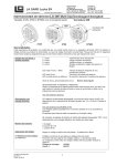
Changing the Safe Code (LG 39E)
Switch off the device. Insert the key into the lock, turn it to the right and open the bottom door of the
BEETLE /iSCAN Tower Line 100.
48
Important Notes, Site Preparation and Commissioning
Now enter the code number of the safe in the data field (1), turn the knob (2) to the right and open the
door.
2
1
Lock 39E
LED
Contact of
the audit trail
Generally
Each pressing of a key is confirmed by a signal (an acoustic signal and a LED flash). A correct code
entering is followed by double signal, the wrong code is followed by triple signal. Pauses longer than
10 sec will cause deleting of all previous entering and you have to start again.
Code entering: Enter the seven-unit numeric code – or a word with 7 characters
a) Operation with parallel code:
a double signal is followed.
(manager mode)
Manager code: 1234567
49
Important Notes, Site Preparation and Commissioning
b) Operation with two codes:
Six unit numeric codes or words with six characters.
(must be programmed)
For opening two valid codes must be entered. The code
sequencing is arbitrary, two of all valid codes can open.
Manager code: 123456 and 654321
Opening:
After entering of a correct code (double signal) the lock is
ready to open for a time of 3 sec.
Turn the keypad by 90° TO THE RIGHT (clockwise) until it
stops. Swingbolt entry is fixed, turn handle boltwork
When during the ready time for opening (3 sec) no opening is
made then the lock will be automatically secured.
Locking:
Turn the keypad back so that it is horizontal. Swingbolt entry
is fixed, turn handle boltwork
Check the lock to be locked.
Wrong try penalty:
After 4 successive wrong code enters the lock will be cut off
for 5 minutes then it will be cut off already after 2 wrong tries.
During this wrong try penalty the LED is flashing each 10 sec.
The key pressing is refused with a triple signal.
Change of code:
The user can change its code by himself anytime.
(at the opened door)
a) Enter the code and keep pressed the last number until the
double signal (LED is on) is repeated, press the “0” and enter
the new code (double signal), enter the new code once more
for its confirmation (double signal).
b) Press “0” for seven times, (when operating with two codes
six times “0“) enter the old code and then two times the new
code (always followed by double signal).
The new code is now active.
In case of wrong entries or pauses during entering the code
longer than 10 sec remains valid the old code. When the new
code would not be accepted (triple signal) then it is too similar
to the code already stored.
Always enter the new code with the door opened.
50
Important Notes, Site Preparation and Commissioning
Silent alarm:
(must be programmed)
In case of blackmailing the silent alarm can be started so that you
enter the last code number +1 (e.g. the last number is 9 and the
alarm is started with the number 0 instead of 9). The lock function
is the same as entering the code for opening.
Time delay for opening:
(must be programmed)
After valid code entering the time delay starts to run, which can be
recognized by the LED signal each 2 sec. After delay period expired the time period for opening starts, which can be recognized
by alternate acoustic and LED signal each second. During the time
period for opening the valid code must be entered to reach the
opening.
At the operation with two codes must two valid codes be entered
during the time period for opening to succeed.
When no valid code is entered during time period for opening the
lock is time secured again.
When the delay should be interrupted press the key “0”.
Time delay override:
(must be programmed)
Power supply:
The user ID# 9 ( WTU ) can open immediately. At the operation
with two codes the ID# 9 is entered as the second code.
When the capacity of the battery is too low a series of acoustic
signals is heard at opening. (According to the capacity of the battery it may be also only 3, 4 or 5 acoustic signals!) Change the
battery!
Use 9V ALKALINE batteries only!
The codes are stored in the lock even without power supply.
The battery compartment is installed down in the keypad.
When connected to the alarm equipment through the interlock
device “SP“ then the power supply is secured from this place.
Safety notice:
Change the code immediately and carefully store on a secure
place, do not use your personal data (telephone number, date of
birth etc.) as a code.
51
Important Notes, Site Preparation and Commissioning
LED and acoustic signals:
1 x short signal
2 x short signal
3 x short signal
6 x short signal
enter confirmation
valid code entered
wrong code, not accepted
remote interlock, the alarm equipment was
not released
LED signal each 10 sec. 1 flashing
Interlocking time after a
wrong entry
LED signal each 2 sec. Time
delay for opening is
running
Alternate LED and acoustic signals
Time period for opening is
running
A series of acoustic signals, ca. 3 sec. Low battery capacity
Still available ca. 10 openings.
Dependent of the battery capacity there may be also less acoustic
signals. Therefore, the battery change should be made also in
case of double or triple signals without ready time for opening.
Use ALKALINE batteries only!
52
Important Notes, Site Preparation and Commissioning
Programming Manager
Manager function
Overview
Manager code*
a)
Manager code change (ID Nr. 0)
function “0”
b)
Enable user (ID Nr. 1-9)
function “1”
c)
Disable user
function “2”
d)
Remove user
function “3”
e)
User status inquiry
function “7”,
keep pressed
f)
Reading the audit trail
function “7”
g)
Setting the time delay for opening
function “9”
It is possible to open the lock with the factory code 1 2 3 4 5 6 7.
Change the code immediately.
A) Manager code change
(at the opened door)
(function 0)
Enter the manager code (or the old code) and keep pressed the
last number until the double signal (LED is on) is repeated, press
the “0” and enter the new code (double signal), enter the new code
once more for confirmation (double signal). The new code is now
active. In case of wrong entries or pauses during entering the code
longer than 10 sec remains valid the old code remains valid.
When the new code is not accepted (triple signal), it is too similar to
the code already stored. Enter a new code.
B) Enable user*
(function 1)
Enter the manager code and keep pressed the last number until
the double signal (LED is on) is repeated, press the “1” (double
signal), enter the user ID No (1-9) e.g. “2” (double signal), enter the
user code (double signal), enter the user code once more for confirmation (double signal).
When a triple signal is followed then the code confirmation was wrong
or the code is too similar to the already stored code. Enter a new
code.
53
Important Notes, Site Preparation and Commissioning
C) Disable user*
(function 2)
Enter the manager code and keep pressed the last number until
the double signal (LED is on) is repeated, press the “2” (double
signal) and enter the user ID Nr. e.g. ”2” (single signal). The user
(ID Nr. 2) is now disabled for such time period until again enabled
with the function „1“ and the ID Nr. "2".
D) Remove user*
(function 3)
Enter the manager code and keep pressed the last number until
the double signal (LED is on) is repeated, press the “3” (double
signal) and enter the ID Nr. e.g. “2” (single signal). The user (ID No
2) is removed.
E) User status inquiry
(function 7)
The Manager can anytime make the inquiry, which user is enabled,
disabled or removed. Enter the manager code and keep pressed
the last number until the double signal (LED is on) is repeated, keep
pressed the “7” until the double signal is once more repeated.
Press the user ID No (1-9) and watch the signal:
1 acoustic signal
= enabled
2 acoustic signals = disabled
3 acoustic signals = removed
Long acoustic signal = disabled, it can not be enabled
Finish: press “0”.
(*) At the operation with two codes (4 eyes principle) the valid user code must be entered before the
manager code to be able to do the programming. Six-unit code, manager 123456.
54
Important Notes, Site Preparation and Commissioning
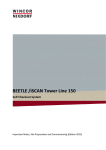
F) Reading the audit trail
In the lock memory records of the last 50 openings are stored with
the user ID, which can be read on a PC or laptop.
PC setup
In a PC with Windows 95 (or later) the program “LG-View 3x“ ("SetupExe") is loaded and the COM port is set with the parameters „1200
bauds, non parity, 8 data bits, 1 stop bit“. When the laptop has no
COM port then this connection must be made with the PCMCIA card
(RS 232) or a corresponding USB adapter. Start the program “LGView 3x“ and set the corresponding port in the item KONFIGURATION (configuration). Connect the interface/data reading cable PN
42160 to the corresponding port.
Start the program „LG-View 3x“ and click with the mouse on the safe
symbol (start acquisition). Insert the interface connector from the side
into the keypad 3750K. For the keypad 3750 on the lock an adapter
cable is used.
Start program
Enter the manager code and keep pressed the last number until the
double signal (LED is on) is repeated and shortly press the “7”. The
data are transferred from the lock to the PC and shown in a list, which
can be printed.
The audit trail can be stored in the PC memory with „SAFE“ and entering the file name with a LOG extension. The program calling is
made with „Load“ (program loading).
Reading the audit trail
(function 7)
The item „Infos“ offers you a message about the lock status. The user
status is shown in a ten-unit group of characters with “manager” first
and second to tenth place the user numbers 1 - 9.
Meaning: I = initialized, code is active.
E = (enrolled) code changed (manager only)
D = (disabled) code disabled.
- = removed, the code can be entered again.
B = blocked, code cannot be enabled.
55
Important Notes, Site Preparation and Commissioning
G) Time delay for opening*
Manager can set the time delay for opening with the function „9“.
(function 9)
The values of the time delay 1-99 minutes and of the time period for
opening 1-19 minutes are entered in a four-unit block where the first
two places are minutes of the delay and the further two places are
minutes of the time period of opening (min. 1 minute).
If the setting should be made with 10 minutes of time delay and 5
minutes of time period for opening then the four-unit block is as follows: „1005“
Enter the manager code and keep pressed the last number until
the double signal (LED is on) is repeated. Press „9“ and enter the
time block „1005“ (double acoustic signal) and confirm with a repeated entering of „1005“ (double acoustic signal).
The changing of the time values can be made only in the time
period for opening.
Time delay override
Lock programming
If the “time delay override” is set then the user ID Nr. 9 can open immediately (e.g. WTU). When operating with two codes then the code
of the ID No 9 is entered as second one. This "override" code of the
ID No 9 can be enabled only in the time period for opening or before
the time delay is set.
The program selection of the lock (two codes, alarm, delay override)
is made by programming on PC (39E Setup) or manually on the keypad.
(*) At the operation with two codes (4 eyes principle) the valid user code must be entered before the
manager code to be able to make the programming. Six-unit code, manager 123456.
56
Important Notes, Site Preparation and Commissioning
Programming on PC
FACTORY-Mode
(Pre-Setup-mode)
The lock may be installed in the factory mode. It is opened
when pressing the key “1” and it sends at the same time the
alarm. Thus the simple and flexible storing is reached and the
simple operation during manufacturing is secured.
Programming on PC
PC setup
On PC (laptop) the operating system Windows must be installed and the program LG-39E-SETUP (requiring 4MB)
must be loaded. Insert the interface cable into the corresponding COM port of your PC. When the laptop has no
COM port this connection must be made with the PCMCIA
card (RS 232) or a corresponding USB adapter. Configure
the port (1200 bauds, non parity,8 data bits, 1 stop bit) and
start the program LG39E-SETUP. The programming is made
in clear text (english) and is very simple.
Code length
When operating with a parallel code (each code is opening) the code length must be of seven-units.
When operating with two codes: The code length is sixunits.
Activate user:
User
The preset codes can be overwritten. The active users to
whom no code was assigned can be enabled later.
Not activated users cannot be enabled later.
Insert the interface connector into the keypad (or into the
adapter) of the lock, which is ready for operation, and click
the mouse on the item “TRANSMIT /Send“ and then press
the key “0” on the lock keypad.
Program transfer:
With this program it is possible to make the programming of
several locks. It is possible to save it for later consumer programming (File/ Save as:..).
Exit the Factory-Mode
After SETUP programming the lock is still in Factory mode
and can be opened with the key “1”. The programming will be
effective when the factory mode is finished: keep pressed “0”
until the double signal is repeated and enter the manager
code. The program must be “frozen” by the change of
manager code. The lock is ready for operation.
57
Important Notes, Site Preparation and Commissioning
Reset to the Factory Mode
When the programs shall be changed the reset with the Reset-Box is necessary for a new programming.
Disconnect the lock from the power supply for ca. 3 minutes
(remove the battery) and insert the Reset-Box into the „BAT“
inlet of the lock.
The lock is in the Factory Mode (opening with key “1”).
The Reset Box must be connected to a 9V ALKALINE battery.
Safety notice
58
Do not assign code to the users of no use for the time being.
Manager can do this later.
Important Notes, Site Preparation and Commissioning
Manual programming
Factory Mode
(Pre-Setup-mode)
The lock may be installed in the factory mode. It is opened
when pressing the key “1” and it sends an alarm.
Thus the simple and flexible storing is reached and the simple operation during installation is secured.
Exit the Factory-Mode
Keep pressed the key “0” until the double signal is repeated.
Now the manager code is 555555.
Code length and program selection
The code length and program selection are made with the
function “8” and a group of two characters. The first place in
this group of characters is the code length the second one is
the program number.
Program 0 = Manager mode (operation with parallel code)
Program 1 = Manager mode with delay override
Program 2 = Operation with two codes
Program 3 = Two code operation with delay override
Program 4 = Manager mode with alarm
Program 5 = Manager mode with alarm and with delay
override
Program 6 = Two code operation with alarm
Program 7 = Two code operation, alarm and delay override
Programming
(function 8)
Enter the manager code “555555” and keep pressed the last
number until the double signal (LED is on) is repeated
and enter “8”. Then enter the group of two characters
made of code length and program number (double signal) and repeat the enter of the group for confirmation
(double signal).
In case of the seven-unit codes the manager code is 7 x “5”.
59
Important Notes, Site Preparation and Commissioning
Enable user
(function 1)
Enter the manager code and keep pressed the last number
until the double signal (LED is on) is repeated then press
“1” and the user ID No (1-9) and enter the code two times.
The disabled users cannot be enabled after the change of the
manager code.
Program “freeze”
With the change of the manager code the program is „frozen“
and it can be changed only with resetting and with a new
programming.
Reset to the Factory Mode
Disconnect the lock from the power supply for ca. 3 minutes
(remove the battery) and insert the Reset-Box into the „BAT“
inlet of the lock.
The Reset Box must be connected to a 9V ALKALINE battery.
The lock is in the Factory mode again (Pre-Setup-Mode).
Safety notice: Do not assign codes to the users of no use for the time being.
Remove the codes. (Function 3 and user number)
60
Important Notes, Site Preparation and Commissioning
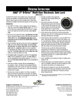
BEETLE /iSCAN Tower Line 100 – Dimensions
61
Important Notes, Site Preparation and Commissioning
62
Important Notes, Site Preparation and Commissioning
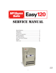
Block Diagram
63
Important Notes, Site Preparation and Commissioning
Environmental Requirements
Operating temperature
EN 60721-3-3; Class 3k3
Climate test according to IEC 68 / EN60068
Ambient temperature:
5° C – 35° C
Humidity:
5% r.h. (1 g/m 3 ) – 85% r.h. (25 g/m3 )
Temperature change:
0.5 K/min (max. 7.5K/30 min)
Barometric pressure:
70 kPa – 106 kPa
(70kPa corresponds to an installation at approximately 3000 meters above sea level) Installation environments with long periods of sunshine should be avoided.
Storage conditions
EN 60721-3-1; Class 1k2
Climate test according to IEC 68 / EN60068
Ambient temperature:
Humidity:
Temperature change:
5° C – 40° C
5% r.h. (1 g/m 3 ) – 85% r.h. (25 g/m3 ) 0.5 K/min
0.5 K/min (max. 7.5K/30 min)
Transport conditions
EN 60721-3-2; Class 2k2
Climate test according to IEC 68 / EN60068
Ambient temperature:
Humidity:
Temperature change:
64
-25 °C – 60° C
15% r.h. (1 g/m 3 ) – 98% r.h. (32 g/m3 )
-25° C / 25° C
Important Notes, Site Preparation and Commissioning
Certifications of the manufacturer
This device complies with the requirements of EEC directive 89/336/EEC
with regard to "Electromagnetic Compatibility" and 73/23/EEC, "Low Voltage
Directive".
Therefore, you will find the CE mark on the device or on its packaging.
Devices without integrated UPS according class B.
Devices without UPS according class A.
Important: Operation of this equipment in a residential area is likely to cause harmful interference in
which case the user will be required to correct the interference at his own expense.
Note on Radio Interference Suppression
All secondary appliances that are connected to an appliance must be equipped with radio interference
suppression in accordance with EC directive 89/336/EEC. Products that fulfill this requirement are
accompanied by an appropriate manufacturers certificate bear the CE-symbol or the radio protection
symbol. Products that do not fulfill these requirements may only be operated with specific permission
of the relevant authorities.
FCC-Class A Declaration
This equipment has been tested and found to comply with the limits for a Class A digital device, pursuant to part 15 of the FCC Rules. These limits are designed to provide reasonable protection against
harmful inter-ference when the equipment is operated in a commercial environment. This equipment
generates, uses, and can radiate radio frequency energy and, if not installed and used in accordance
with the instruction manual, may cause harmful interference to radio communications.
Operation of this equipment in a residential area is likely to cause harmful interference in which case
the user will be required to correct the interference at his own expense. Modifications not authorized
by the manufacturer may void users authority to operate this device. This class A digital apparatus
complies with Canadian ICES-003.
Cet appareil numerique de la classe A est conforme à la norme NMB-003 du Canada.
65
Important Notes, Site Preparation and Commissioning
Recycling the BEETLE /iSCAN Tower Line 100
The BEETLE /iSCAN Tower Line 100 was designed according to the Wincor Nixdorf standard
"Environmentally Conscious Product Design and
Development”.
The BEETLE /iSCAN Tower Line 100 is manufactured without the use of CFCs and CCHs and is
manufactured to a great extent out of materials
and components which are recyclable.
For recycling purposes do not attach any additional
adhesive labels to the device.
Wincor Nixdorf disposes of old devices in an environmentally responsible manner at a recycling center that is ISO 9001 and ISO 14001 certified, as is
the entire company.
Follow your local regulations on the disposal of toxic waste (such as the system ribbons).
Your Wincor Nixdorf vendor will answer any questions you have concerning returns, recycling, and
disposal of our products.
66
Wincor Nixdorf International GmbH
D-33094 Paderborn
01750111493C