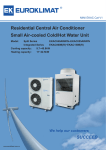
1
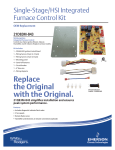
Service Facts UH1-DH1-SF-1H Upflow/ Horizontal, Downflow/ Horizontal, Gas-Fired, Direct Vent, Condensing, Single Stage Furnaces: *UH1B040A9241A *UH1B060A9361A *UH1B080A9421B *UH1C080A9601A *UH1C100A9481A *UH1D100A9601A *UH1D120A9601A *DH1B040A9241A *DH1B065A9421A *DH1C085A9481A *DH1D110A9601A *__First letter may be “A” or “T” IMPORTANT — This document contains a wiring diagram and service information. This is customer property and is to remain with this unit. Please return to service information pack upon completion of work. WARNING DISCONNECT POWER BEFORE SERVICING PRODUCT SPECIFICATIONS 1 MODEL TYPE RATINGS 2 Input BTUH 3 Capacity BTUH (ICS) 3 Temp. rise (Min.-Max.) °F. BLOWER DRIVE Diameter - Width (In.) No. Used Speeds (No.) CFM vs. in. w.g. Motor HP R.P.M. Volts / Ph / Hz COMBUSTION FAN - Type Drive - No. Speeds Motor HP - RPM Volts / Ph / Hz FLA FILTER — Furnished? Type Recommended Hi Vel. (No.-Size-Thk.) VENT PIPE DIAMETER — Min (In.) 56 HEAT EXCHANGER Type - Unfired Gauge (Fired) ORIFICES — Main Nat. Gas. Qty. — Drill Size L.P. Gas Qty. — Drill Size GAS VALVE PILOT SAFETY DEVICE Type BURNERS — Type Number POWER CONN. — V / Ph / Hz 4 Ampacity (In Amps) Max. Overcurrent Protection (Amps) PIPE CONN. SIZE (IN.) DIMENSIONS Crated (In.) WEIGHT Shipping (Lbs.) / Net (Lbs.) *UH1B040A9241A Upflow / Horizontal *UH1B060A9361A Upflow / Horizontal *UH1B080A9421B Upflow / Horizontal 40,000 38,000 30 - 60 DIRECT 9x7 1 4 See Fan Performance Table 1/5 1075 115/1/60 Centrifugal Direct - 1 1/55 - 3000 115/1/60 1.0 No High Velocity 1 - 17x25 - 1in. 2 Round 60,000 57,000 30 - 60 DIRECT 10 x 7 1 4 See Fan Performance Table 1/3 1075 115/1/60 Centrifugal Direct - 1 1/15 - 3450 115/1/60 1.75 No High Velocity 1 - 17x25 - 1in. 2 Round 77,000 73,150 35 - 65 DIRECT 11 x 8 1 4 See Fan Performance Table 1/2 1075 115/1/60 Centrifugal Direct - 1 1/20 - 3450 115/1/60 0.71 No High Velocity 1 - 17x25 - 1in. 2 Round Aluminized Steel - Type I Aluminized Steel - Type I Aluminized Steel - Type I 20 20 20 2 — 45 2 — 56 Redundant - Single Stage 3 — 45 3 — 56 Redundant - Single Stage 4 — 45 4 — 56 Redundant - Single Stage Hot Surface Ignition Multiport Inshot 2 115/1/60 5.2 15 1/2 HxWxD 41-3/4 x 19-1/2 x 30-1/2 Hot Surface Ignition Multiport Inshot 3 115/1/60 9.2 15 1/2 HxWxD 41-3/4 x 19-1/2 x 30-1/2 Hot Surface Ignition Multiport Inshot 4 115/1/60 10.2 15 1/2 HxWxD 41-3/4 x 19-1/2 x 30-1/2 139 / 129 150 / 140 158 / 148 Notes 1 Central Furnace heating designs are certified to ANSI Z21.47 / CSA 2.3. 2 For U.S. applications, above input ratings (BTUH) are up to 2,000 feet, derate 4% per 1,000 feet for elevations above 2,000 feet above sea level. For Canadian applications, above input ratings (BTUH) are up to 4,500 feet, derate 4% per 1,000 feet for elevations above 4,500 feet above sea level. 3 Based on U.S. government standard tests. 4 The above wiring specifications are in accordance with National Electrical Code; however, installations must comply with local codes. 5 Refer to the Vent Length Table in the Installer's Guide or the Allowable Vent Length label located on the furnace. 6 All *UH1 and *DH1 furnace models have a vent outlet diameter that equals 2". NOTICE: Since the manufacturer has a policy of continuous product and product data improvement, it reserves the right to change design and specifications without notice. © 2012 Trane All Rights Reserved Service Facts PRODUCT SPECIFICATIONS 1 MODEL TYPE RATINGS 2 Input BTUH 3 Capacity BTUH (ICS) 3 Temp. rise (Min.-Max.) °F. BLOWER DRIVE Diameter - Width (In.) No. Used Speeds (No.) CFM vs. in. w.g. Motor HP R.P.M. Volts / Ph / Hz COMBUSTION FAN - Type Drive - No. Speeds Motor HP - RPM Volts / Ph / Hz FLA FILTER — Furnished? Type Recommended Hi Vel. (No.-Size-Thk.) VENT PIPE DIAMETER — Min (In.) 56 HEAT EXCHANGER Type - Fired - Unfired Gauge (Fired) ORIFICES — Main Nat. Gas. Qty. — Drill Size L.P. Gas Qty. — Drill Size GAS VALVE PILOT SAFETY DEVICE Type BURNERS — Type Number POWER CONN. — V / Ph / Hz 4 Ampacity (In Amps) Max. Overcurrent Protection (Amps) PIPE CONN. SIZE (IN.) DIMENSIONS Crated (In.) WEIGHT Shipping (Lbs.) / Net (Lbs.) *UH1C080A9601A Upflow / Horizontal *UH1C100A9481A Upflow / Horizontal *UH1D100A9601A Upflow / Horizontal *UH1D120A9601A Upflow / Horizontal 80,000 76,000 30 - 60 DIRECT 11 x 10 1 4 See Fan Performance Table 3/4 1100 115/1/60 Centrifugal Direct - 1 1/20 - 3450 115/1/60 0.71 No High Velocity 1 - 20x25 - 1in. 3 Round 97,000 92,150 35 - 65 DIRECT 10 x 10 1 4 See Fan Performance Table 1/2 1075 115/1/60 Centrifugal Direct - 1 1/20 - 3450 115/1/60 0.71 No High Velocity 1 - 20x25 - 1in. 3 Round 97,000 92,150 35 - 65 DIRECT 11 x 10 1 4 See Fan Performance Table 3/4 1100 115/1/60 Centrifugal Direct - 1 1/20 - 3450 115/1/60 0.71 No High Velocity 1 - 24x25 - 1in. 3 Round 110,000 104,500 40 - 70 DIRECT 11 x 10 1 4 See Fan Performance Table 3/4 1100 115/1/60 Centrifugal Direct - 1 1/20 - 3450 115/1/60 0.71 No High Velocity 1 - 24x25 - 1in. 3 Round Aluminized Steel - Type I Aluminized Steel - Type I Aluminized Steel - Type I Aluminized Steel - Type I 20 20 20 20 4 — 45 4 — 56 Redundant - Single Stage 5 — 45 5 — 56 Redundant - Single Stage 5 — 45 5 — 56 Redundant - Single Stage 6 — 45 6 — 56 Redundant - Single Stage Hot Surface Ignition Multiport Inshot 4 115/1/60 13.5 20 Hot Surface Ignition Multiport Inshot 5 115/1/60 12.5 20 Hot Surface Ignition Multiport Inshot 5 115/1/60 12.9 20 Hot Surface Ignition Multiport Inshot 6 115/1/60 12.9 20 1/2 HxWxD 41-3/4 x 23 x 30-1/2 1/2 HxWxD 41-3/4 x 23 x 30-1/2 1/2 HxWxD 41-3/4 x 26-1/2 x 30-1/2 1/2 HxWxD 41-3/4 x 26-1/2 x 30-1/2 171 / 160 171 / 160 197 / 185 205 / 193 Notes 1 Central Furnace heating designs are certified to ANSI Z21.47 / CSA 2.3. 2 For U.S. applications, above input ratings (BTUH) are up to 2,000 feet, derate 4% per 1,000 feet for elevations above 2,000 feet above sea level. For Canadian applications, above input ratings (BTUH) are up to 4,500 feet, derate 4% per 1,000 feet for elevations above 4,500 feet above sea level. 3 Based on U.S. government standard tests. 4 The above wiring specifications are in accordance with National Electrical Code; however, installations must comply with local codes. 5 Refer to the Vent Length Table in the Installer's Guide or the Allowable Vent Length label located on the furnace. 6 All *UH1 and *DH1 furnace models have a vent outlet diameter that equals 2". 2UH1-DH1-SF-1H Service Facts PRODUCT SPECIFICATIONS 1 MODEL TYPE RATINGS 2 Input BTUH 3 Capacity BTUH (ICS) 3 Temp. rise (Min.-Max.) °F. BLOWER DRIVE Diameter - Width (In.) No. Used Speeds (No.) CFM vs. in. w.g. Motor HP R.P.M. Volts / Ph / Hz COMBUSTION FAN - Type Drive - No. Speeds Motor HP - RPM Volts / Ph / Hz FLA FILTER — Furnished? Type Recommended Hi Vel. (No.-Size-Thk.) VENT PIPE DIAMETER — Min (In.) 56 HEAT EXCHANGER Type - Fired - Unfired Gauge (Fired) ORIFICES — Main Nat. Gas. Qty. — Drill Size L.P. Gas Qty. — Drill Size GAS VALVE PILOT SAFETY DEVICE Type BURNERS — Type Number POWER CONN. — V / Ph / Hz 4 Ampacity (In Amps) Max. Overcurrent Protection (Amps) PIPE CONN. SIZE (IN.) DIMENSIONS Crated (In.) WEIGHT Shipping (Lbs.) / Net (Lbs.) *DH1B040A9241A Downflow / Horizontal *DH1B065A9421A Downflow / Horizontal *DH1C085A9481A Downflow / Horizontal *DH1D110A9601A Downflow / Horizontal 40,000 38,000 30 - 60 DIRECT 10 x 7 1 4 See Fan Performance Table 1/5 1080 115/1/60 Centrifugal Direct - 1 1/55 - 3000 115/1/60 1.14 No High Velocity 2 - 14x20 - 1in. 2 Round 60,000 57,000 25 - 55 DIRECT 11 x 8 1 4 See Fan Performance Table 1/2 1075 115/1/60 Centrifugal Direct - 1 1/25 - 3200 115/1/60 1.35 No High Velocity 2 - 14x20 - 1in. 2 Round 80,000 76,000 30 - 60 DIRECT 11 x 10 1 4 See Fan Performance Table 1/2 1075 115/1/60 Centrifugal Direct - 1 1/20 - 3450 115/1/60 0.71 No High Velocity 2 - 16x20 - 1in. 2.5 Round 110,000 104,500 35 - 65 DIRECT 11 x 10 1 4 See Fan Performance Table 3/4 1100 115/1/60 Centrifugal Direct - 1 1/20 - 3450 115/1/60 0.71 No High Velocity 2 - 16x20 - 1in. 2.5 Round Aluminized Steel - Type I Aluminized Steel - Type I Aluminized Steel - Type I Aluminized Steel - Type I 20 20 20 20 2 — 45 2 — 56 Redundant - Single Stage 4 — 48 4 — 56 Redundant - Single Stage 5 — 48 5 — 56 Redundant - Single Stage 6 — 48 6 — 56 Redundant - Single Stage Hot Surface Ignition Multiport Inshot 2 115/1/60 4.8 15 Hot Surface Ignition Multiport Inshot 4 115/1/60 11.4 15 Hot Surface Ignition Multiport Inshot 5 115/1/60 12.5 20 Hot Surface Ignition Multiport Inshot 6 115/1/60 12.9 20 1/2 HxWxD 41-3/4 x 19-1/2 x 30-1/2 1/2 HxWxD 41-3/4 x 19-1/2 x 30-1/2 1/2 HxWxD 41-3/4 x 23 x 30-1/2 1/2 HxWxD 41-3/4 x 26-1/2 x 30-1/2 145 / 135 158 / 148 171 / 160 205 / 193 Notes 1 Central Furnace heating designs are certified to ANSI Z21.47 / CSA 2.3. 2 For U.S. applications, above input ratings (BTUH) are up to 2,000 feet, derate 4% per 1,000 feet for elevations above 2,000 feet above sea level. For Canadian applications, above input ratings (BTUH) are up to 4,500 feet, derate 4% per 1,000 feet for elevations above 4,500 feet above sea level. 3 Based on U.S. government standard tests. 4 The above wiring specifications are in accordance with National Electrical Code; however, installations must comply with local codes. 5 Refer to the Vent Length Table in the Installer's Guide or the Allowable Vent Length label located on the furnace. 6 All *UH1 and *DH1 furnace models have a vent outlet diameter that equals 2". UH1-DH1-SF-1H 3 Service Facts ! WARNING ▲ CARBON MONOXIDE POISONING HAZARD Failure to follow the steps outlined below for each appliance connected to the venting system being placed into operation could result in carbon monoxide poisoning or death. The following steps shall be followed for each appliance connected to the venting system being placed into operation, while all other appliances connected to the venting system are not in operation: 1. Seal any unused openings in the venting system. 2. Inspect the venting system for proper size and horizontal pitch, as required in the National Fuel Gas Code, ANSI Z223.1/NFPA 54 or the CAN/CGA B149 Installation Codes and these instructions. Determine that there is no blockage or restriction, leakage, corrosion and other deficiencies which could cause an unsafe condition. 3. As far as practical, close all building doors and windows and all doors between the space in which the appliance(s) connected to the venting system are located and other deficiencies which could cause an unsafe condition. 4. Close fireplace dampers. 5. Turn on clothes dryers and any appliance not connected to the venting system. Turn on any exhaust fans, such as range hoods and bathroom exhausts, so they are operating at maximum speed. Do not operate a summer exhaust fan. 6. Follow the lighting instructions. Place the appliance being inspected into operation. Adjust the thermostat so appliance is operating continuously. 7. If improper venting is observed during any of the above tests, the venting system must be corrected in accordance with the National Fuel Gas Code, ANSI Z221.1/NFPA 54 and/or CAN/CGA B149 Installation Codes. 8. After it has been determined that each appliance connected to the venting system properly vents where tested as outlined above, return doors, windows, exhaust fans, fireplace dampers and any other gas-fired burning appliance to their previous conditions of use. ! WARNING ▲ FIRE OR EXPLOSION HAZARD Failure to follow the safety warnings exactly could result in serious injury, death or property damage. Never test for gas leaks with an open flame. Use a commercially available soap solution made specifically for the detection of leaks to check all connections. A fire or explosion may result causing property damage, personal injury, or loss of life. ! WARNING ▲ FIRE OR EXPLOSION HAZARD Failure to follow the safety warnings exactly could result in serious injury, death or property damage. Improper servicing could result in dangerous operation, serious injury, death, or property damage. ! CAUTION ▲ The integrated furnace control is polarity sensitive. The hot leg of the 115 VAC power must be connected to the BLACK field lead. SEQUENCE OF OPERATION Thermostat call for heat R and W thermostat contacts close signaling the control module to run its self-check routine. After the control module has verified that the pressure switch contacts are open and the limit switch(es) contacts are closed, the draft blower will be energized. As the induced draft blower comes up to speed, the pressure switch contacts will close and the ignitor warm up period will begin. The ignitor will heat for approximately 20 seconds, then the gas valve is energized to permit gas flow to the burners. The flame sensor confirms that ignition has been achieved. After the flame sensor confirms within a 4 second trial period that ignition has been achieved, the delay to fan ON period begins timing. After approximately 45 seconds the indoor blower motor will be energized and continue to run during the heating cycle. Downflow models have a 10 second blower ON delay. When the thermostat is satisfied, R and W thermostat contacts open, the gas valve will close, the flames will extinguish, and the induced draft blower will be de-energized. The indoor blower motor will continue to run for the fan off period (Field selectable at 60, 100, 140 or 180 seconds), then be de-energized by the control module. 4UH1-DH1-SF-1H Service Facts AIRFLOW ADJUSTMENT Check inlet and outlet air temperatures to make sure they are within the ranges specified on the furnace rating nameplate. If the airflow needs to be increased or decreased, see the wiring diagram for information on changing the speed of the blower motor. ! WARNING ▲ Disconnect power to the unit before removing the blower door. Failure to follow this warning could result in personal injury from moving parts. This unit is equipped with a blower door switch which cuts power to the blower and gas valve causing shutdown when the door is removed. Operation with the door removed or ajar can permit the escape of dangerous fumes. All panels must be securely closed at all times for safe operation of the furnace. ! WARNING ▲ BODILY INJURY CAN RESULT FROM HIGH VOLTAGE ELECTRICAL COMPONENTS, FAST MOVING FANS, AND COMBUSTIBLE GAS. FOR PROTECTION FROM THESE INHERENT HAZARDS DURING INSTALLATION AND SERVICING, THE ELECTRICAL SUPPLY MUST BE DISCONNECTED AND THE MAIN GAS VALVE MUST BE TURNED OFF. IF OPERATING CHECKS MUST BE PERFORMED WITH THE UNIT OPERATING, IT IS THE TECHNICIANS RESPONSIBILITY TO RECOGNIZE THESE HAZARDS AND PROCEED SAFELY. INDOOR BLOWER TIMING Heating: The control module controls the indoor blower. The blower start is fixed at 45 seconds after ignition. Downflow models have a 10 second blower ON delay. The FAN-OFF period is field selectable by dip switches at 60, 100, 140, or 180 seconds. The factory setting is 100 seconds (See wiring diagram). Cooling: The fan delay off period is factory set at 0 seconds. The option for 80 second delay off is field selectable (See wiring diagram). The following warning complies with State of California law, Proposition 65. ! WARNING ▲ This product contains fiberglass wool insulation! Fiberglass dust and ceramic fibers are believed by the State of California to cause cancer through inhalation. Glasswool fibers may also cause respiratory, skin, or eye irritation. PRECAUTIONARY MEASURES ● Avoid breathing fiberglass dust. ● Use a NIOSH approved dust/mist respirator. ● Avoid contact with the skin or eyes. Wear long-sleeved, loose-fitting clothing, gloves, and eye protection. ● Wash clothes separately from other clothing: rinse washer thoroughly. ● Operations such as sawing, blowing, tear-out, and spraying may generate fiber concentrations requiring additional respiratory protection. Use the appropriate NIOSH approved respirator in these situations. FIRST AID MEASURES Eye Contact – Flush eyes with water to remove dust. If symptoms persist, seek medical attention. Skin Contact – Wash affected areas gently with soap and warm water after handling. The following warning complies with State of California law, Proposition 65. ! WARNING ▲ Hazardous Gases! Exposure to fuel substances or by-products of incomplete fuel combustion is believed by the state of California to cause cancer, birth defects, or other reproductive harm. NOTE: Direct drive motors have bearings which are permanently lubricated and under normal use, lubrication is not recommended. UH1-DH1-SF-1H 5 Service Facts WIRING DIAGRAM From Dwg. D343498P01 Rev. 2 (continued on next page) 6UH1-DH1-SF-1H Service Facts SCHEMATIC DIAGRAM From Dwg. D343498 Rev. 2 UH1-DH1-SF-1H 7 Service Facts WIRING DIAGRAM (continued on next page) From Dwg. D343814P01 Rev.0 8UH1-DH1-SF-1H Service Facts SCHEMATIC DIAGRAM From Dwg. D343814P01 Rev.0 UH1-DH1-SF-1H 9 Service Facts PERIODIC SERVICING REQUIREMENTS ! WARNING ▲ Disconnect power to the unit before removing the blower door. Failure to follow this warning could result in personal injury from moving parts. 1. GENERAL INSPECTION – Examine the furnace installation annually for the following items: a. All flue product carrying areas external to the furnace (i.e. chimney, vent connector) are clear and free of obstruction. A vent screen in the end of the vent (flue) pipe must be inspected for blockage annually. b. The vent connector is in place, slopes upward and is physically sound without holes or excessive corrosion. c. The return air duct connection(s) is physically sound, is sealed to the furnace and terminates outside the space containing the furnace. d. The physical support of the furnace should be sound without sagging, cracks, gaps, etc., around the base so as to provide a seal between the support and the base. e. There are no obvious signs of deterioration of the furnace. 2. FILTERS – Filters should be cleaned or replaced (with high velocity filters only), monthly and more frequently during high use times of the year such as midsummer or midwinter. 3. BLOWERS – The blower size and speed determine the air volume delivered by the furnace. The blower motor bearings are factory lubricated and under normal operating conditions do not require servicing. If motor lubrication is required it should only be done by a qualified servicer. Annual cleaning of the blower wheel and housing is recommended for maximum air output, and this must be performed only by a qualified servicer or service agency. ! WARNING ▲ CARBON MONOXIDE POISONING HAZARD Failure to follow the service and/or periodic maintenance instructions for the furnace and venting system, could result in carbon monoxide poisoning or death. NOTE: On LP (propane) units, some light yellow tipping of the outer mantle is normal. Inner mantle should be bright blue. Natural gas units should not have any yellow tipped flames. This condition indicates that a service call is required. For best operation, burners should be cleaned annually by a qualified servicer. NOTE: On LP (propane) units, due to variations in BTU content and altitude, servicing may be required at shorter intervals. 6. HEAT EXCHANGER/FLUE PIPE – These items must be inspected for signs of corrosion, and/or deterioration at the beginning of each heating season by a qualified service technician and cleaned annually for best operation. To clean flue gas passages, follow recommendations below: a. Turn off gas and electric power supply. b. Inspect flue pipe exterior for cracks, leaks, holes or leaky joints. Some discoloration of PVC pipe is normal. c. Remove burner compartment door from furnace. d. Inspect around insulation covering flue collector box. Inspect induced draft blower connections from recuperative cell and to the flue pipe connection. e. Remove burners. (See 5.) Do NOT touch igniter. It is extremely hot. Failure to follow this warning could result in severe burns. f. Use a mirror and flashlight to inspect interior of heat exchanger, be careful not to damage the igniter, flame sensor or other components. 4. IGNITER – This unit has a special hot surface direct ignition device that automatically lights the burners. Please note that it is very fragile and should be handled with care. g. If any corrosion is present, contact a service agency. Heat exchanger should be cleaned by a qualified service technician. h. After inspection is complete replace burners, and all furnace doors. i. Restore gas supply. Check for leaks using a soap solution. Restore electrical supply. Check unit for normal operation. ! WARNING ▲ ! WARNING ▲ CARBON MONOXIDE POISONING HAZARD Failure to follow the service and/or periodic maintenance instructions for the furnace and venting system, could result in carbon monoxide poisoning or death. 5. BURNERS – Gas burners do not normally require scheduled servicing, however, accumulation of foreign material may cause a yellowing flame or delayed ignition. Either condition indicates that a service call is required. For best operation, burners should be cleaned annually by a qualified servicer. Turn off gas and electric power supply. To clean burners, remove burner box cover (6 to 8 screws) and the top burner bracket. Lift burners from orifices. NOTE: Be careful NOT to break igniter when removing burners. Clean burners with brush and/or vacuum cleaner. Reassemble parts by reversal of the above procedure. 7. FURNACE CONDENSATE DRAIN TUBES – Condensate drain tubes must be checked periodically to assure that condensate can flow freely from unit to drain. If a drain problem cannot be corrected, call a qualified servicer. 8. COOLING COIL CONDENSATE DRAIN – If a cooling coil is installed with the furnace, condensate drains should be checked and cleaned periodically to assure that condensate can drain freely from coil to drain. If condensate cannot drain freely water damage could occur. (See Condensate Drain in Installer’s Guide.) ! CAUTION ▲ Label all wires prior to disconnection when servicing controls. Wiring errors can cause improper and dangerous operation. Verify proper operation after servicing. 10UH1-DH1-SF-1H Service Facts FURNACE AIRFLOW (CFM) VS. EXTERNAL STATIC PRESSURE (in. w.c.) MODEL SPEED TAP 0.10 0.20 0.30 0.40 0.50 0.60 0.70 0.80 0.90 *UH1B040A9241A 4321- HIGH - Black MED.-HIGH - Blue MED.-LOW - Yellow** LOW - Red 1043 940 837 729 992 895 798 694 930 841 752 657 885 791 705 600 812 726 649 545 740 650 560 478 647 559 438 376 518 420 305 220 457 390 279 178 *UH1B060A9361A 4321- HIGH - Black MED.-HIGH - Blue** MED.-LOW - Yellow LOW - Red 1359 1232 1077 926 1313 1199 1054 913 1264 1161 1027 895 1204 1116 994 871 1144 1065 953 836 1079 1004 904 792 1004 934 845 733 919 852 768 670 812 744 666 570 *UH1B080A9421B 4321- HIGH - Black MED.-HIGH - Blue** MED.-LOW - Yellow LOW - Red 1646 1366 1175 1004 1611 1356 1159 994 1573 1337 1145 997 1530 1311 1130 982 1477 1280 1108 963 1421 1243 1081 943 1360 1197 1045 907 1289 1139 993 866 1200 1060 929 824 *UH1C080A9601A 4321- HIGH - Black MED.-HIGH - Blue MED.-LOW - Yellow** LOW - Red 2235 1921 1618 1334 2194 1904 1604 1331 2152 1888 1591 1327 2105 1861 1577 1320 2057 1835 1563 1313 1987 1797 1539 1290 1916 1760 1515 1266 1836 1698 1466 1229 1757 1636 1416 1192 *UH1C100A9481A 4321- HIGH - Black MED.-HIGH - Blue** MED.-LOW - Yellow LOW - Red 1982 1892 1759 1593 1912 1832 1712 1557 1836 1765 1660 1521 1761 1696 1604 1485 1679 1621 1536 1433 1593 1538 1465 1370 1496 1446 1383 1294 1389 1342 1275 1182 1267 1205 1149 1068 *UH1D100A9601A 4321- HIGH - Black MED.-HIGH - Blue MED.-LOW - Yellow** LOW - Red 2339 2045 1719 1436 2287 2021 1703 1430 2235 1996 1693 1430 2168 1947 1671 1414 2100 1897 1649 1398 2021 1836 1607 1372 1941 1774 1565 1344 1858 1701 1498 1287 1773 1629 1431 1230 2380 2042 1695 1402 2334 2029 1690 1404 2287 2016 1684 1406 2241 1984 1668 1397 2193 1952 1652 1387 2118 1892 1627 1358 2043 1830 1601 1328 1956 1771 1545 1285 1870 1712 1489 1242 4 - HIGH - Black 3 - MED.-HIGH - Blue** *UH1D120A9601A 2 - MED.-LOW - Yellow 1 - LOW - Red *= First letter may be "A" or "T" ** = Factory Set Heat Speed Tap Setting CFM VS. TEMPERATURE RISE MODEL *UH1B040A9241A Cubic Feet Per Minute (CFM) 600 700 800 900 1000 1100 1200 1300 1400 1500 1600 1700 1800 1900 2000 2100 2200 2300 2400 59 50 44 39 35 59 53 *UH1B060A9361A 48 44 41 38 *UH1B080A9421B 64 59 54 50 47 44 41 *UH1C080A9601A 64 59 54 50 47 44 41 *UH1C100A9481A 68 63 59 55 52 49 46 44 *UH1D100A9601A 68 63 59 55 52 49 46 44 42 40 38 37 70 66 62 59 56 53 50 48 46 44 *UH1D120A9601A *= First letter may be "A" or "T" UH1-DH1-SF-1H 11 Service Facts FURNACE AIRFLOW (CFM) VS. EXTERNAL STATIC PRESSURE (in. w.c.) MODEL SPEED TAP 0.10 0.20 0.30 0.40 0.50 0.60 0.70 0.80 0.90 *DH1B040A9241A 4321- HIGH - Black MED.-HIGH - Blue MED.-LOW - Yellow** LOW - Red 998 856 753 647 965 832 728 617 922 797 694 581 870 751 650 538 807 695 596 490 735 628 533 435 653 550 460 375 561 462 378 308 459 363 286 235 *DH1B065A9421A 4321- HIGH - Black MED.-HIGH - Blue** MED.-LOW - Yellow LOW - Red 1501 1442 1346 1225 1453 1393 1308 1197 1402 1341 1263 1160 1344 1285 1212 1116 1283 1227 1155 1062 1216 1166 1092 1001 1145 1103 1024 931 1068 1037 950 853 986 968 869 766 *DH1C085A9481A 4321- HIGH - Black MED.-HIGH - Blue** MED.-LOW - Yellow LOW - Red 1835 1726 1581 1401 1772 1674 1539 1374 1709 1622 1498 1346 1637 1557 1440 1308 1566 1492 1383 1269 1485 1416 1321 1209 1405 1340 1258 1148 1313 1252 1172 1075 1222 1164 1085 1001 *DH1D110A9601A 4321- HIGH - Black MED.-HIGH - Blue** MED.-LOW - Yellow LOW - Red 2147 1995 1712 1424 2074 1940 1681 1408 2000 1885 1649 1392 1941 1827 1602 1367 1881 1767 1555 1341 1807 1699 1505 1296 1732 1631 1455 1251 1655 1547 1381 1188 1576 1462 1307 1124 *= First letter may be "A" or "T" ** = Factory Set Heat Speed Tap Setting CFM VS. TEMPERATURE RISE MODEL *DH1B040A9241A *DH1B065A9421A Cubic Feet Per Minute (CFM) 600 700 800 900 1000 1100 1200 1300 1400 1500 1600 1700 1800 1900 2000 2100 2200 59 50 44 39 35 75 66 59 53 48 44 41 38 35 70 64 59 54 50 47 44 41 39 37 88 81 74 69 65 60 57 54 51 *DH1C085A9481A *DH1D110A9601A 48 46 *= First letter may be "A" or "T" 12UH1-DH1-SF-1H Service Facts Troubleshooting Flowchart Index 14) IFC Component Layout 15) LED Flash Codes 16) Getting started 17) 2 Flash Troubleshooting Retry and Recycle Lockout 19) 3 Flash Troubleshooting Pressure Switch Fault 20) 4 Flash Troubleshooting High Limit and Auxiliary Limit 21) 4 Flash Troubleshooting Roll Out Limit 22) 5 Flash Troubleshooting Flame Sensed Fault 23) 6 Flash Troubleshooting Polarity Revered or Poor Ground Fault 24) 7 Flash Troubleshooting External Gas Valve Circuit Fault 25) 8 Flash Troubleshooting Low Flame Sense Fault 26) 9 Flash Troubleshooting Igniter Faults 27) Furnace PSC Fan Motor – No Air Flow The following pages include troubleshooting flowcharts in reference to the 95% Single Stage furnaces ONLY; using the FAULT LED as starting points. The information contained is for reference only and does not cover all scenarios or problems that may be encountered by a qualified field technician. Only qualified technicians should attempt to install, troubleshoot, or repair this appliance. Failure to follow all cautions and/or warnings could result in personal or property damage; including death. UH1-DH1-SF-1H 13 Service Facts Integrated Furnace Control (IFC) Component Layout Single Stage 95% Condensing Furnace Integrated Furnace Control (IFC) Component Layout Line Voltage Connections COOL-H E16 E17 HEAT-H PARK E18 E28 PARK LINE-H E27 EAC-H E13 XFMR-H HUM-H E14 LINE-IN E20 K3 HUM-N EAC-N U2 XFMR-N Q9 K2 OFF K1 E8 E9 E10 E11 1 2 3 1 2 3 ON CIR-N E7 S1 Dip Switches to configure Heat/Cool Delay Options E1 24 volt Furnace Component Connections 5 AMPS TWIN DS1 Fault LED (Red) Y W R G Control Fuse C E34 50A65-475 CNT03076 TWIN Y W R G C Low Voltage Terminal Strip Downflow Models use control board 50A65-477 CNT05995 14UH1-DH1-SF-1H Service Facts Fault LED Flash Codes Definitions INTEGRATED FURNACE CONTROL ERROR FLASH CODES Flashing Slow --- Normal - No call for Heat Flashing Fast --- Normal - Call for Heat Continuous ON --- Replace IFC Continuous OFF --- Check Power 2 Flashes --- System Lockout (Retries or Recycles exceeded) 3 Flashes --- Pressure Switch Error 4 Flashes --- Open High Limit Device 5 Flashes --- Flame sensed when no flame should be present 6 Flashes --- 115 Volt AC power reversed or Poor Grounding 7 Flashes --- Gas valve circuit error 8 Flashes --- Low flame sense signal 9 Flashes --- Check Ignitor UH1-DH1-SF-1H 15 Service Facts GETTING STARTED Is high voltage power supplied to the unit? NO Repair high voltage connection to unit. YES Close and hold door switch Is the IFC LED flashing? YES What is the fault light flash code? See FAULT LED Flash Codes page NO Is 24VAC low voltage present from transformer and fuse good NO Repair low voltage wiring, replace transformer, or fuse as needed YES Are connections and wiring in working condition? YES Replace IFC NO Repair connections Refer to Gas Furnace Silicon Nitride Ignitor Models Service Manual to supplement this information. Publication Number 34-3405-08 16UH1-DH1-SF-1H Service Facts DEFINITION 2 Flash Fault LED RETRY Lock Out = 3 unsuccessful tries for ignition within a single call for heat Flame has never been sensed RECYCLE Lock Out = 10 recycles within a single call for heat. Flame is sensed & then lost Disconnect electrical power to furnace. Connect manometer to inlet gas pressure connector Is inlet gas pressure above 14" WC or less than nameplate minimum ? Correct inlet gas pressure Check operation Downflow model *DH1D110A960 only: Outlet gas pressure ~4.5"WC (NG) ~11"WC (LP) Downflow model *DH1B065A942 only: Outlet gas pressure ~3.0"WC (NG) ~9.5"WC (LP) NO Cycle power to furnace and call for heat Does gas ignite? YES NO Is outlet gas pressure ~3.5"WC (NG) ~11.0"WC (LP) NO NO Downflow model *DH1D110A960 only: Adjust manifold gas pressure to ~4.5"WC (NG) ~11"WC (LP) Downflow model *DH1B065A942 only: Outlet gas pressure ~3.0"WC (NG) ~9.5"WC (LP) Check operation Adjust manifold gas pressure to ~3.5"WC (NG) ~11.0"WC (LP) Check operation YES YES Clean and align burners correctly. Check operation NO Do all burners ignite within 5 seconds? Does inlet gas pressure drop more than 2" WC Check igniter position and correct if needed. Check operation YES For CORRECT positioning of the igniter and flame sensor, see figure on next page UH1-DH1-SF-1H Correct inlet gas pressure Check operation NO Replace Gas Valve Check operation NO YES Measure flame current. Is flame current less than 1 micro-amp? (3-4 ua = Normal) YES YES Is flame sensor located correctly? NO NO Flame sensor is good Correct and check operation YES Replace flame sensor. Check operation Disconnect electrical power to furnace. Connect manometer to oulet gas pressure connector Cycle power to furnace and call for heat Is minimum outlet gas manifold pressure maintained? 17 Service Facts 18UH1-DH1-SF-1H Service Facts 3 Flash Fault LED DEFINITION An error has occurred with the P.S. The error will be reported, indicating that the pressure switch is either opened or closed, contrary to normal operating sequence. In most cases, the pressure switch is not the problem. Cycle power to furnace and call for heat. Note: Verify all wiring to pressure switch is correct per wiring diagram Is the inducer motor running? NO YES Disconnect electrical power from the furnace and remove 1 wire from the pressure switch Pressure switch is okay Is 24 volts present, measured across PS (orange to yellow)? See Note #1 NO Replace pressure switch. Check operation. YES Is continuity measured across PS? NO YES Check PS hose, flue piping for obstruction and/or NO confirm vent size is correct NO Is pressure greater than pressure switch label? See Note #2 Pressure switch is okay. Re attach wire to PS YES Replace pressure switch. Check operation. Is 120 volts measured between the IFC IND-H to IND-N? YES Note #1 24 volts = Open Switch 0 volts = Closed Switch Note #2 Measured pressure is negative, greater than refers to magnitude only. Disconnect electrical power from the furnace and check TCO-B NO Replace IFC. Check operation. Is TCO-B open? NO Replace Inducer. Check operation. YES Replace Inducer Limit switch YES Allow time for Inducer Limit to cool and investigate cause for high vent temperatures. Is Inducer Limit cool and contacts open? UH1-DH1-SF-1H 19 Service Facts DEFINITION Limit switches are safety devices that will open when an abnormal high temperature has been sensed. REMOVE ALL JUMPER WIRING TO SWITCHES! Under no circumstances, shall these switches be left jumpered when not troubleshooting. See next page for additional 4 flash faults 4 Flash Fault LED Disconnect electrical power to furnace Replace filter and clean blower wheel. Check operation NO Are filter & blower wheel clean? YES Check set screw position and motor bearings. Correct or replace as needed. Check operation NO Does blower wheel turn freely? YES Ignition occurs and FAN ON delay begins Cycle power to furnace and call for heat Does fan come on after ~45 seconds? (Downflow models after 10 seconds) NO YES Is 120 VAC measured at IFC between HEAT-H and CIR-N? YES Is 120 VAC measured to motor? NO NO Replace furnace control Check operation Repair wiring harness. Check operation YES Check motor and capacitor. Repair or replace as needed Down Flow Models Only Correct application YES or duct issues. Check operation Is external static pressure greater than nameplate? YES NO Is heat rise within specification? See Service Facts YES NO Is return air temperature above 85 F? Correct gas pressure Check operation NO NO Check for loose insulation or other objects within furnace air stream Is temperature at auxilary limit switch above specifications? NO Replace auxiliary limit switch YES YES Is outlet manifold gas pressure within specifications? Does motor continue to run during the entire heating cycle? Return air temperature is above max limit YES Is temperature at high limit above the switch setting? Make sure any temperature measuring devices (thermocouples, dial thermometers) used to estimate limit temperature are within ¼ inch of limit measurement point YES Check for excessive reverse flow during an off cycle NO Replace high limit switch 20UH1-DH1-SF-1H Service Facts DEFINITION: 4 Flash Fault LED Limit switches are safety devices that will open when an abnormal high temperature has been sensed. REMOVE ALL JUMPER WIRING TO SWITCHES! Under no circumstances, shall these switches be left jumpered when not troubleshooting. Is a Manual Reset, Flame Rollout Switch open? Downflow Models only: Is this a downflow *DH1 model? YES YES YES Install correct size orifices Check operation NO Is the burner orifice size 56? Or matched to Installers Guide for LP? YES YES NO Install correct size orifices Check operation YES Check combustion air blower, venting, heat exchanger for blockage (i.e. sooting) Are the burner orifice size 48 for NG? Is LP gas being used? NO YES Disconnect electrical power to furnace Correct as needed Check operation YES Is flue piping restricted? NO Check flue pipe for correct sizing and long horizontal runs or slope less than ¼” per linear foot. Correct as needed Remove, clean, and reassemble burners. Push RED reset on both rollout switches Are all burner flames directed into heat exchanger with a tight pattern? (inadequately aired burners tend to roll back) Cycle power to furnace and call for heat Check burner alignment Correct as needed Check operation NO Ignition occurs Do all burners ignite within 5 seconds? NO NO YES YES Are flames from burners impinging on sides of heat exchanger? When fan comes on, do flames stay consistent? NO Replace heat exchanger Check operation YES Replace Roll out switch Check operation UH1-DH1-SF-1H 21 Service Facts DEFINITION: 5 Flash Fault LED Flame is sensed when it should not be sensed. Disconnect electrical power to furnace Turn off gas supply! Remove gas valve Are there signs of moisture or debris in the inlet gas screen? YES Inspect gas supply for leaks and have gas supplier check gas quality Install drip leg per National Fuel Gas Code and Installation Instructions NO NO Is there a drip leg installed on inlet gas piping per installation instructions? YES Using a back-up wrench, install new gas valve Check operation 22UH1-DH1-SF-1H Service Facts DEFINITION: Ground Fault - Incoming or chassis ground connection is not sensed Polarity Fault – Incoming high voltage wiring is reversed 6 Flash Fault LED Line Voltage Too Low - Line voltage must not be below 97 VAC Connect volt meter to white incoming neutral wire and green earth ground Reverse 120 vac power leads to furnace wiring Disconnect incoming electrical power to furnace YES Does meter read ~120 vac? YES Correct neutral and ground problem. Furnace must be on a dedicated circuit. NO Reconnect power Check operation Connect volt meter to black incoming and chassis ground at burner box Correct earth ground. Check operation NO Is there a voltage greater than 10 VAC Disconnect incoming electrical power to furnace NO NO Does meter read ~120 vac? YES Disconnect incoming electrical power to furnace Check / correct all ground connections within furnace for continuity Check operation UH1-DH1-SF-1H 23 Service Facts 7 Flash Fault LED DEFINITION: External Gas Valve Circuit Error (24 volts is present when it should not be present) Turn Comfort Control to “OFF” position Is 24 VAC nominal voltage present between Red lead at gas valve connection to chassis ground? YES Correct wiring Check operation NO Replace IFC 24UH1-DH1-SF-1H Service Facts UH1-DH1-SF-1H 25 Service Facts 9 Flash Fault LED DEFINITION: Triac Fault – The triac reduces voltage applied to the ignitor. A voltage error has been sensed Damaged Triac Ignitor Fault – The control board has sensed that the ignitor circuit is open or shorted. The Ignition system is very dependent on good earth ground connections. A poor earth ground can result in multiple ignitor and/or triac failures. Disconnect electrical power to the furnace Disconnect ignitor and check resistance of ignitor Replace ignitor. Check operation Verify all ground connections NO Is resistance reading between 11 – 18 ohms? YES Replace the IFC. Check operation Verify all ground connections. Check ignitor for wire insulation damage. YES Good Triac Check Triac Is it damaged? NO Check all wiring for insulation damage and connection integrity NO Is there wiring or insulation damage? YES Repair or replace wiring. Check operation 26UH1-DH1-SF-1H Service Facts TROUBLESHOOTING Furnace PSC fan motor - No Air Flow Turn the FAN switch to “ON” at the thermostat Is there any air flow? NO Is the fan wheel running? Check for dirty air filter, duct work damage or restrictions around the air handler coil and repair as needed YES NO Is the high voltage power supplied to the unit? Repair high voltage connection to unit. NO YES Is 24 VAC measured between “R” (transformer hot) and “B/C” (transformer common) at the low voltage field connections? Is the proper line voltage present at the transformer? NO YES Is fuse blown? YES Replace fuse. NO Repair wiring between incoming power supply and transformer. YES Is 24 VAC measured between “G” and “B/ C” at the low voltage connections? NO Replace transformer. Check thermostat and wiring to thermostat. NO YES Is line voltage measured between motor common and applied speed tap at IFC? CIR-N and HEAT-H NO YES NO Replace the IFC Replace run capacitor. Is microfarad reading of fan motor run capacitor within 10% of rated value? Replace fan motor and run capacitor. YES UH1-DH1-SF-1H 27 Service Facts Literature Order Number UH1-DH1-SF-1H UH1-DH1-SF-1H File Number Trane 6200 Troup Highway Tyler, TX 75707 For more information contact your local dealer (distributor) SupersedesUH1-DH1-SF-1G Date08/12 Since the manufacturer has a policy of continuous product and product data improvement, it reserves the right to change design and specifications without notice.