1
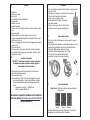
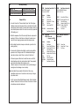
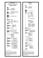
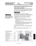
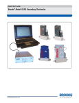
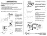
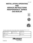
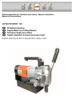
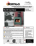
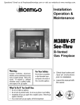
SMARTESTER User Manual The Professionals Choice PO Box 21 2230 Landmark Place Allenwood, NJ USA 732-223-6644 Fax 732-223-1617 www.supco.com [email protected] RAW p/n 19204 Sealed Unit Parts Co., inc. PO Box 21 2230 Landmark Place Allenwood, NJ USA Introduction Applications The SmarTester is a non-intrusive hand-held diagnostic tool for troubleshooting electronic ignition systems of gas-fired heating appliances, water heaters and more. It monitors electronic signals of various equipment components and power supplies through its unique interface cables. The SmarTester works along side the internal test circuitry of the equipment and is capable of quickly diagnosing a number of problems within multiple circuits of the equipment control system simultaneously. Hard to find intermittent problems are easily solved. The service technician can then make a Smart decision to repair the equipment. IMPORTANT!!!! 1. The SmarTester Diagnoses the Following 1.1 Inspections and Installations Loss of Power (24VAC &115VAC) Proper Venting (Pressure Switch) Proper Duct Size (Cycling on Limit) Thermostat for Proper Cycling Flame Sensor (MicroAmps) 1.2 The SmarTester is intended to be used by a qualified HVAC service technician. Always use proper techniques while testing to avoid damaging the control terminals, connectors, or interface cable. In cases where equipment wires are to be removed for testing, always label them prior to disconnection. Wiring errors can cause improper and dangerous operation of the equipment. Always refer to the equipment manual provided by the manufacturer prior to servicing any equipment. Always make sure all power to the system being tested is off; plug the interface cable into the SmarTester, then make the connections on the control board. Make sure all wiring connections are secured correctly and are snug. A wet control board could cause bodily harm; never test controls that have been wet. Replace them. Troubleshooting (Highlights Only) Inducer Motor Slowdown Due to Secondary Heat Exchanger Problems (Pressure Switch) Thermostat Circuit for Intermittent Problems Short Cycling Due to Partially Blocked Vent (Pressure Switch) Air flow (Limit) Intermittent problems 1.3 Preventative Maintenance Proper Sequence of Operation Timing of Ignition Warm-Up, Fan Timer, etc. Detects intermittent problems in the thermostat circuit Detects a quick drop-out of pressure switch Can measure accuracy of a pressure switch closing with the use of a manometer On polarized equipment, detects reverse polarity on the 24VAC side. Detects a loss of source voltage (24VAC and 115VAC) Detects open circuits Detects a limit dropping out before thermostat is satisfied Measures microAmps in the flame rectification circuit A wet or damaged control board may create erroneous information. WARNING!! Using the interface cable on a control board not listed in this manual or on the SUPCO website could damage the equipment or SmarTester, or could pose a shock hazard. USE ONLY WITH RECOMMENDED CONTROLS!! Improper use of this unit could cause death, serious injury, or property damage 9 volt battery required (Not Included) 2 3 1.4 Benefits Each circuit that is connected to the SmarTester is supported by a green or red LED. LED lights are in sequence of operation on the instrument Track to hold an application card in place Built-in, auto-on microAmp meter Battery operated (9V) long life LCD display Low battery indicator Plug-in port on top of meter for interface cable Hands-free Quick & easy setup Saves time Tests multiple circuits simultaneously No guesswork Reduces call backs Reduces frustration Pinpoints the current problem and future problems with one simple test No wire-stripping Reads multiple circuits within minutes of the service call Pinpoints intermittent problems that the flashing LED on the circuit board may not pick up No more struggling with hard-to-read wiring diagrams and checking single circuits Work flow continuity Checks accuracy of a pressure switch with a partner manometer Feel confident while working with circuit boards, electronics and a large number of wires. 2.0 Instrument 2.1 Protective boot with convenient hanging hook 2.2 Smart Interface Cables Each circuit in the interface cable is wired in parallel for passive diagnostics Each interface cable application is wired differently for each circuit board series. Application wiring is done in the Interface Cable. WR50 and HWSV interface cables are 46 long. WR42 and WR42WC adapter cables are 10 long. All connections are made with Molex® style connectors to prevent an improper connection SmarTester Components The SUPCO SmarTester consists of three main components. Combining them together provides an analyzer specific to standardized control board circuitry. The SmarTester Instrument is the same for all control boards. Smart Card Application Overlays. Smart Interface Cables. The SmartInterface Cables & Overlays are designed for a specific control board technology. Currently, the SmarTester, Interface Cables and Overlays can support the following series control boards: Honeywell Smart Valve - SV95XX Series White Rodgers 50AXX Series 2.3 Smart Card Overlays 3 Smart Cards: Match Smart Card to corresponding board model number We continue to expand the capabilities of the SmarTester; check our website, http://www.supco.com/SmarTester, for the latest updated list. HWSVC 4 WR50C WR5042C Each Smart Card supplies minimum requirements for microAmp readings and matching Interface Cable information. 5 SmarTester Setup Installation and operation of the SmarTester is unique for each control board circuitry. Go to the appropriate section that corresponds to the control board being analyzed. 3.0 Honeywell Smart Valve This SmartInterface cable and Smart Card used in conjunction with the SmarTester Instrument will analyze the following Smartvalve models. SV9401 SV9402 SV9403 SV9500 SV9600 SV9501 SV9502 SV9503 SV9601 SV9602 Warning!! Using this interface cable on a control not listed could damage the equipment or SmarTester, or could pose a shock hazard. USE ONLY WITH RECOMMENDED CONTROLS! Before doing any tests, always check for correct 115VAC-supply voltage to equipment. Incorrect supply voltage may give you a false reading with the SmarTester. Using The SmarTester 3.1 Shut off the power to system. Slide the Smart Valve Smart Card Interface Overlay (HWSVC) under the integral slots on the SmarTester. Connect the Smart Valve Interface cable to the SmarTester. Turn the thermostat all the way up. If necessary, carefully bypass blower door safety switch for TEMPORARY TESTING PURPOSES. Unplug the Molex® connectors from the valve. Connect 2 of the HWSVC connectors to the valve and the other 2 to the appliance harness connectors. Be sure to connect clip wire to the common side of the transformer. If transformer does not have a common side, use a clean chassis ground. Turn on the main power. Note: Cables connection are male and female and will only connect 1 way The Power, Polarity and MicroAmp Display will come on automatically when 24VAC or 115VAC are present. If the LED and display do not come on check power supply to equipment again and the SmarTester 9 volt battery. Follow sequence of operation: Watch for dimming of 115VAC LED or 24VAC LED, this will indicate possible low voltage. Left columns of LEDs are 24VAC circuits, right column LEDs are 115VAC circuits. 6 Green LEDs indicate NORMAL operation and are lit only when power is applied. Red LEDs indicate an open circuit and potential problem.. 3.2 Normal Sequence of Operation: No call for heat: (Power Applied to Equipment) 24VAC LED Lit 24VAC Polarity LED Lit Operating Controls LED Lit Note: The first red LED will glow showing Operating Controls Open This is a normal function on start up for systems with a draft inducer fan. All other LEDs off. Call for heat : 24VAC LED Lit 24VAC Polarity LED Lit Operating Controls LED Lit until pressure switch closes Gas Valve will click for Pilot Gas supply Ignitor LED Lit Ignitor glows Pilot lights MicroAmp Reading Present. (Read Quickly) Main Valve LED Lit. Main Burner Ignition Ignitor LED off Normal Heat Cycle 3.3 MicroAmp Reading: Model No. SV9500/SV9600 Minimum MicroAmp Reading .12 ua Minimum SV9401/SV9402/SV9403/SV9501 SV9502/SV9503/SV9601/SV9602 1.3 ua Minimum 3.4 Diagnostic Tips: 1. If no LEDs are lit, check power to system being tested and SmarTester battery. 2. If the red LED indicating Operating Controls Open Circuit is lit, this may include pressure switch, thermostat, vent damper, rollouts, limits and other controls as this system has all operating controls connected in series. 3. If the red LED indicating Operating Controls Open Circuit is lit and the inducer motor does not start to run, look for an open fuse on Board. 7 4. With a normally open pressure switch, if the Operating Control LED does not glow, check for a stuck closed pressure switch. 5. After the inducer motor has come up to speed, the Operating Control LED should go out. If not check for voltage using a Multimeter. (All Limits and Pressure Switches are connected in series) Pressure Switch: If open, check: Pressure Switch Pressure Switch Tubing for blockage or leaks Inducer Assembly/ Inducer Blower Wheel Flue for blockage Limits: Follow limit circuit checking each limit and connecting wiring. 7. Watch the sequence of the LEDs and verify that each component is operating. If LEDs are lit but there is no pilot or main burner, check to make sure you have supply gas and all valves are open. 8. Check microAmps by watching when pilot comes on, but before main burner lights, for a more accurate reading. If microAmps are weak, clean the pilot and flame sensor for better reading. (Best if Flame Sensor is replaced) 9. Record microAmp reading in customer record for future reference. 10. After locating the problem, always re-check and cycle until unit is working properly. 11. Remove bypass from blower door safety switch if bypassed. 4.0 White Rodgers 50A50 and related Control circuits WR50: This SmartInterface cable and WR50C Smart Card used in conjunction with the SmarTester Instrument will analyze the following models and many more*. White-Rodgers 50A50 -110, 111, 112, 113, 142, 209, 286, 296, 405, 406, 408, 438, 471, 472, 473,474 50A55 - 286, 143, 241, 438, 474, 571 50A65 - 475-02 Johnson Controls G951ABD - 1403 York 031 - 01234 - 000 When used with the included 4 terminal Molex® to 2 terminal Molex® adapters this interface cable will work with: 50A50 - 205, 206, 207, 285, 288, 295 50A55 - 285 Warning!! Using this interface cable on a control not listed could damage the equipment or Smartester, or could pose a shock hazard. 8 USE ONLY WITH RECOMMENDED CONTROLS! Before doing any tests, always check for correct 115VAC supply voltage to equipment. Incorrect supply voltage may give you a false reading with the SmarTester. 4.1 Using the SmarTester: Shut off the power to system. Slide the Smart Card Overlay (WR50C / WR5042C) under the integral tabs on the SmarTester. Connect to the WR50 Smart Interface Cable. Turn the thermostat all the way up. If necessary, carefully bypass blower door safety switch for TEMPORARY TESTING PURPOSES Unplug the system Molex® type connectors from the control board. Connect the matching SmarTester connectors to the ignition control board. Then connect the SmarTester Molex® connectors to the system connectors. Turn on the main power Note: Cable connections are male and female and will only connect 1 way The Power, Polarity and MicroAmp Display will come on automatically when 24VAC or 115VAC are present. If the LED and display do not come on check power supply to equipment again and the SmarTester 9 volt battery. Follow sequence of operation: Watch for dimming of 115VAC LED or 24VAC LED, this will indicate possible low voltage. Left columns of LEDs are 24VAC circuits, right column LEDs are 115VAC circuits. Green LEDs indicate NORMAL operation and are lit only when power is applied. Red LEDs indicate an open circuit and potential problem. 4.2 Normal Sequence of Operation: No call for heat Power LED Lit Polarity LED Lit MicroAmp Display (Erratic-Low) All other LEDs off. Call for heat: Power LED Lit Polarity LED Lit MicroAmp Display Thermostat Closed LED Lit Pressure Switch Open LED Lit Inducer LED Lit Pressure Switch LED Off Ignitor LED Lit Main Valve/EFT LED Lit Burner Ignition Ignitor LED MicroAmp Reading Present (May Have Fluctuations) Normal Heat Cycle 9 4.3 MODEL NO 50A50 209/230 All other 50A50 and 50A55 4.4 Complete Kits: MicroAmp Reading: Minimum MicroAmp Reading 0.30 ma 0.15 ma Diagnostic Tips: 1. On a call for heat, the Pressure Switch Open red LED will glow indicating an open pressure switch. This is a normal function with a normally open pressure switch. If the LED does not glow, check for a stuck-closed pressure switch. After motor has come up to speed the LED should go out. 2. Watch the sequence of the LEDs and verify that each component is operating. If LEDs are lit but there is no flame to the main burner, check for correct supply gas pressure and all valves are open. STSVK SmarTester Smart Valve Kit For Use With Honeywell 1st Generation SV95XX SI50K SmarTester Interface Kit For Use With White Rodgers 50A50, 50A55, etc Includes: ST100 HWSVC HWSV SCDM STVIDEO Includes: SmarTester Smart Card Smart Valve Cable Soft Case Instructional DVD WR50C WR5042C WR50 WR42 WR42WC STMANUAL STFC Instruction Manual SmarTester Flow Chart ST50K SmarTester WR50A Series Kit 1st Generation SV95XX Includes: ST100 WR50C WR5042C WR50 WR42 WR42WC SCDM STVIDEO STMANUAL STFC 3. After locating the problem, always re-check and cycle until unit is working properly. 4. On some units, the flame rollout safety is wired in series with the gas valve circuit. If the gas valve LED is illuminated and the gas valve does not open, check if there is a rollout in that circuit. 5. If the burner goes out after short run and there are no red LEDs, control board goes into retry and system re-lights. The equipment may do this several times before lockout occurs. Check for loose wire in Pressure Switch circuit, partial blockage in sensing tube, flue blockage or low microAmp. Optional Accessories: Includes: SmarTester Smart Card 50A Series Smart Card 50A 4 to 2 Cable 50A Series Adapter Cable 50A 4 to 2 Adapter Cable 50A w/Clip Soft Case Instructional DVD Instruction Manual SmarTester Flow Chart SCCP Smart Card 50Series Smart Card 50A 4 to 2 Cable 50A Series Adapter Cable 50A 4 to 2 Adapter Cable 50A w/ Ground Clip Soft Case SI50K SmarTester Interface Kit/ Smart Valve HWSVC HWSV SCCP Smart Card Smart Valve Cable Soft Case Note: SmarTester Pressure Switch LED will blink if this or any intermittent event occurs in the control circuit, but only as long as the problem exists. 6. On 031- Johnson Control/White Rodgers boards. If the SmarTester indicates Blown Fuse but there is no fuse or the fuse is not blown, this indicates a shorted or bad board. 10 11 WR50 Flow Chart Upon Connection of Cables and Line Voltage Applied to Appliance Smart Valve Flow Chart * Clean or replace flame sensor * Clean or replace flame sensor The diagnostics used in this chart illustrate some of the possible scenarios. With service knowledge and experience gained through use of the SmarTester, many more troublesome service problems will become easily diagnosed. The diagnostics used in this chart illustrate some of the possible scenarios. With service knowledge and experience gained through use of the SmarTester, many more troublesome service problems will become easily diagnosed. 12 13