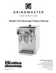
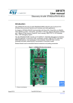
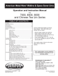
1
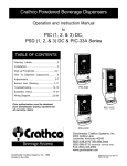
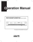
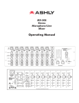
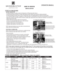
Crathco® Beverage Dispensers
Operator Manual
Assembly
1
PLACE BEARING SLEEVE ON
GUIDE PIN
Note flat sides on outside of
guide pin and on inside of
bearing sleeve.
Line flat sides up until bearing
sleeve slides down over
guide pin and rests
on the cooling plate.
Bearing Sleeve
2
PLACE IMPELLER OVER
BEARING SLEEVE.
Impeller
PLACE BOWL GASKET ON BOWL
Turn bowl upside down and place
bowl gasket over the neck of the
bowl. Moisten gasket with water or
or thin film of lubricant.
NOTE: On D112 units place bowl
gasket around cooling dome.
4
6
INSTALL LOCKDOWN WASHER OR CLAMPS
Standard Units:
• Place lockdown washer over guide pin.
• Push lockdown washer down and
into locking keyway.
• Turn lockdown washer clockwise to
lock into place.
Put impeller over bearing
sleeve with fin side up.
3
PLACE PUMP COVER OVER GUIDE PIN
Place the pump cover over the guide pin
with the spray tube toward the front.
Note that the tab on the front of the pump
cover fits between the 2 locator buttons
or ridges on the bowl. Mini units - bent
part of spray tube faces front of bowl.
NOTE: Use agitator cover in
place of pump cover and spray tube for
fresh juice, drinks that foam (iced tea or
dairy products), or heavy viscous drinks.
5
PUT BOWL ON BASE
Place the neck of the bowl over center of the cooling
plate and with a back and forth downward motion, push bowl
down into place.
NOTE: On D112 units, place bowl over the gasket and cooling
dome with the neck of the bowl centered on the cooling dome.
Mini Units:
• Place lockdown washer
over guide pin.
• Push lockdown washer
down and into locking
keyway.
• Slide into locked
position.
LOCKDOWN
WASHER
LOCKING KEYWAY
3/8” TAB
PUMP COVER
CROSS RIBS
“FRONT” OF
DISPENSER
(TOWARD VALVE AT
FRONT OF BOWL)
HEAD OF GUIDE PIN
D112 Superbowl Units:
• Insert each lockdown clamp
in a lockdown pin and snap
down into place.
(Lock down 2 clamps closest to
the front of the bowl first.)
7
ASSEMBLE VALVE
AND HANDLE
VALVE
O-RING
Place handle (C) in the
two V-cuts in the front of
the handle bracket (B) and
push handle back.
From inside bowl, lower
the valve (A) through the
outlet hole, and through HANDLE
the hole in the handle.
Release handle.
1. HOLD HANDLE IN “V”
NOTCHES & LIFT REAR
OF HANDLE UP.
2. FROM INSIDE THE
BOWL, LOWER THE
VALVE THROUGH
OUTLET HOLE, AND
THROUGH HOLE IN
THE HANDLE.
3. RELEASE HANDLE
8
REPLACE DRIP PAN(S)
Place cover/grid on drip pan.
Place top edge of drip pan up
under lip on front panel.
Lower each drip pan so that the
tab goes down into the tab slot
and locks pan in place.
Regular units proceed to step 15.
Whipper units proceed to step 9.
FRONT PANEL LIP
BASEPLATE
TAB
SLOTS
Assembly (cont.)
9
VALVE HOLE
(WHIPPER UNITS ONLY)
PRESS SPRING UP INTO
PLACE AGAINST THE BOTTOM
OF THE BOWL.
RUBBER INLET ADAPTER
SPRING
10
(WHIPPER UNITS ONLY)
INSERT HANDLE INTO “V”
NOTCHES IN BOWL AND
PLACE VALVE INTO HOLE
(INSIDE BOWL).
“W” IS
WHIPPER
VALVE
(WHIPPER UNITS ONLY)
14 ASSEMBLE THE
Assemble white rubber inlet
adapter by stretching one end
over the large tubular inlet on top
of the whipper housing. Attach
the other end over the ring sleeve
on the underside of the handle.
15
TOP
Ring sleeve on
bottom of handle
Rubber inlet
adapter
Plastic whipper
housing
FILL BOWL(S) WITH PRODUCT
and place lid(s) on bowl(s).
Turn spray switch on first then refrigeration.
HANDLE SHOULDERS GO
INTO “V’ NOTCHES
I/ON
SPRAY
O/OFF
I/ON
REFRIG.
O/OFF
VALVE HOLE
RINGSLEEVE
DOWN
SPRING
11
(WHIPPER UNITS ONLY)
TURN VALVE 90° TO
LOCK.
Cross slot (located on top
of valve) should run left to
right across the bowl when
locked.
12
(WHIPPER UNITS ONLY)
13
(WHIPPER UNITS ONLY)
IMPORTANT: NEVER RUN REFRIGERATION UNLESS
SPRAY OR AGITATE IS ON.
(LOOKING DOWN INTO BOWLS)
CROSS-SLOT
VALVE DOWN IN HOLE
READY TO LOCK
AFTER 90° TURN,
VALVE IS LOCKED
PUSH WHIPPER BLADE
INTO PLACE.
Replace the whipper blade by
lining up the flat inside the blade
with the flat side of the motor
shaft. Push blade firmly into
place.
REPLACE WHIPPER CHAMBER
Replace whipper chamber by
positioning the medium-sized
opening up and tilting 1/8 turn to the
right. Put whipper chamber over
whipper blade and turn to the left
until it locks into place.
Page 2
Crathco® Beverage Dispensers
DISASSEMBLY
1
DRAIN ALL BEVERAGE FROM BOWLS
4
REMOVE PUMP COVER
Remove pump cover by
lifting up on spray tube.
5
REMOVE BOWL AND
BOWL GASKET
Twist bowl back and forth
while lifting up. Bowl gasket
will be around bottom of
bowl.
A. Remove bowl lid(s) and drip tray(s)
B. Drain through valve then
C. Tip unit forward, gently press spray
tube back a short distance to lift the
edge of the pump cover to allow
remaining beverage in well to be
drained through valve.
2a.
STANDARD & MINI UNITS:
REMOVE VALVE AND HANDLE
Lift valve. Handle drops into
operator’s other hand.
NOTE: On D112 units, bowl
gasket will be around cooling
dome.
2b.
WHIPPER UNITS:
• DISASSEMBLE THE RUBBER INLET
ADAPTER
Remove one end from the large tubular inlet
on top of the whipper housing and the
other end from the ring sleeve on the
underside of the handle.
Ring sleeve on
bottom of handle
Rubber inlet
adapter
Plastic whipper
housing
• REMOVE WHIPPER CHAMBER
Turn whipper chamber to the right until it
releases and you can pull it off of the
whipper blade.
REMOVE IMPELLER
AND BEARING
SLEEVE
Remove impeller and
bearing sleeve by
lifting them straight
up.
NOTE: Check impeller and
bearing sleeves for
wear.
See page 5.
6
Impeller
7
• REMOVE WHIPPER BLADE
Pull whipper blade off of the motor shaft.
VALVE
• TURN VALVE 90° TO UNLOCK.
REMOVE HANDLE AND VALVE.
VALVE HOLE
• REMOVE SPRING FROM
BOTTOM OF BOWL.
3
Bearing
Sleeve
THOROUGHLY CLEAN ALL PARTS IN WARM WATER
USING A MILD NON-ABRASIVE DETERGENT AND
RINSE THOROUGHLY.
CAUTION: ABRASIVES WILL SCRATCH PLASTIC PARTS.
WASH BOWL LIDS IN COOL OR LUKEWARM WATER TO
AVOID LEAKS DUE TO SEALED SURFACE BEING
DAMAGED.
HANDLE
SPRING
REMOVE LOCKDOWN WASHER(S)
Standard Unit: Twist lockdown
washer counterclockwise, slide
to release keyway. Then lift out.
Mini Unit: Slide to release
keyway, then lift out.
D112 Unit: Release each clamp.
Crathco® Beverage Dispensers
SANITIZE
Immerse parts in sanitizing solution for 1-2 minutes.
Remove parts from sanitizing solution and drain.
DO NOT RINSE. Place parts on a clean surface to air dry.
Wipe the machine, condensate tray and cooling plate
depression with a cloth wetted with sanitizer solution.
IMPORTANT: Never pour dry powder, crystals, or concentrate
into a dry bowl. Premixing beverage in separate container is
recommended. If mixing in bowl, always add water first.
Page 3
ROUTINE MAINTENANCE: For all Models
Cleaning Your Dispenser
To optimize performance or when using dairy products, clean unit daily.
Regular cleaning of bowl components will result in maximum pumping efficiency, proper seating and sealing, and
prevention of leaks at the valve O-Ring and bowl gasket by removing dried-on beverage solids and pulp from moving sealed parts.
1. Wash all bowl components regularly. Follow all local health codes.
* Refer to Disassembly, Cleaning, and Assembly instructions on pages 1-3.
Sanitizing Your Dispenser
* Refer to Disassembly and Assembly instructions on pages 1-3.
1. In the bowl, mix one gallon of Oxford Chemical’s Disinfectant/Sanitizer Formula C or its equivalent.
2. Turn on spray motor(s) and allow sanitizer to spray around inside of bowl for a period of time as recommended by
the sanitizer manufacturer. Formula C is satisfactory for this purpose when mixed in a solution of 1 liquid ounce of
cleaner to 4 gallons of water. Run spray motor(s) for 60 seconds. In areas with extreme hard water, consult the
local health authority.
3. Drain sanitizer completely and thoroughly during each step of the cleaning process (wash, rinse, and sanitize).
Refer to tips on draining in Disassembly Guide on page 3.
HELPFUL HINTS
1. Noisy Impeller: Do not run impeller dry. The impeller will make a chattering sound in an empty bowl. Remove the
impeller and run a small amount of water in the bowl.
2. Valve and O-Ring: On the first installation, if there is an after-drip, place your hand on the valve and with a slight
downward pressure turn it slightly. This will help seat the o-ring so that it is properly aligned
with the valve seat. If an o-ring becomes cut or worn it should be replaced. If you are pumping
VALVE CAP
a product which has excessive pulp, a separate valve weight may be purchased to add extra
weight so the o-ring will press down against the pulp and guarantee a positive shut-off.
3. Valve Cap Use: The Valve Cap (Part # 2039) insures that a tight valve seal will occur with
products containing heavy pulp. The Valve Cap can be installed by placing it on top of the
VALVE
Valve after the Valve has been assembled into the bowl. See Figure A.
4. High Water Marks on Bowl: When you agitate, you may get “high water marks” as the
beverage level drops. Keep the bowl as full as possible. Frosted bowls are available which
are helpful in reducing the appearance of water marks.
5. To Spray or Not to Spray: Most beverages can be sprayed. It is best not to spray iced tea,
iced coffee, natural juices, or beverages that foam (whipped drinks). A special agitator plate is
Figure A
used in place of a pump cover and spray tube to promote circulation.
6. Proper Cooling: Always keep spray switch on when refrigeration switch is on. A unit must
spray or agitate to cool. Failure to do this will cause impeller to lock-up. The dispenser is
designed to run 24 hours a day. Keep both spray and agitate on when beverage is in the bowls.
7. Condensation: Condensation on the bowls and lids is natural, cool, and refreshing. The amount of condensation
is affected by humidity. Condensation will run down the front panel into the drip tray. Remember to occasionally
empty the drip trays.
8. Single Bowl Operation: If you find it necessary to run your dispenser with only one bowl containing beverage,
put one half (1/2) cup of water in the unused cooling plate depression(s) for best one-bowl operation and
efficiency.
Page 4
Crathco® Beverage Dispensers
PREVENTATIVE MAINTENANCE
Top of Impeller
Bottom of Unused Impeller
Inner center section should be
flush with exterior part
of impeller.
Figure B
1) Wash all bowl components regularly.
2) Wash impeller and bearing sleeve individually and check for
wear.
a) Check for wear on bearing sleeve (flange should be
1.77mm thick - thickness of penny or quarter). (Figure C)
b) Check for wear on impeller (inner white center section
should be flush with colored part of impeller). (Figure B)
c) If bearing sleeve or impeller do not spin freely or are worn
- replace them. (Figure F)
d) Worn parts can cause personal injury, impair cooling and
can damage machine. (Figure D & E)
3) Check valve o-rings and bowl gaskets for wear or damage replace every 6 months or as needed.
4) Every 6 months or more often if needed: unplug unit, remove
panels, clean condenser and interior. (Remove dust and lint
from fins with a soft brush and vacuum.)
5) For further information, visit www.grindmaster.com or
call (800) 695-4500.
New bearing sleeve
Figure C
3220
Large Blue Impeller
(D & WD model)
1161
Small Red Impeller
(E model)
Universal Impeller (all models)
1008
Valve O-ring
1012
Bowl Gasket - for D, WD models
5 gallon (or 3 gallon) bowl
1013
Bowl Gasket for E model and/or 9 liter bowl
2010
Bowl Gasket for 12 gallon SuperBowls (D112)
1150
Bearing Sleeve for 12 gallon Super Bowl (D112)
1983
Crathco® Beverage Dispensers
flange (approx. 1.77mm - thickness of
penny or quarter)
Worn bearing sleeve (replace
when worn to approx. 1mm or 1/2
thickness of penny or quarter).
Figure D
Figure E
Part #s for Preventative Maintenance
Description
Part #
Bearing Sleeve (all units except D112)
Bottom of
Worn Impeller
Replace when worn.
Yellow or white area no
longer flush but indented.
Figure F
worn flange
Bearing sleeve with flange missing
is extremely worn. Discard
immediately.
CAUTION: Handle with care. Sharp
edges may cause personal injury or
damage to machine.
Bearing sleeve and impeller
should spin freely when
held like this. If parts do not
spin freely or are worn, unit
will not cool properly and
worn parts may damage
machine.
3587
Universal Impeller
(Part # 3587)
Page 5
TROUBLESHOOTING GUIDE
PROBLEM
No or partial Refrigeration:
Compressor Runs
POSSIBLE CAUSE
• Condenser clogged with dust or lint
NOTE: Unit must spray or agitate
properly to obtain cooling
• Unit not properly spraying or agitating
• Faulty fan motor
• Loss of refrigerant
No Refrigeration:
Compressor Does Not Run
SOLUTION
• Unplug unit, remove panels and clean out all
lint and dust from condenser and inside
machine. Use vacuum cleaner or bottle
brush.
• See “Problem” - “No Spray or Agitation”
• Replace motor (call for service)
• Call for service
• Call for service
No Spray or Agitation:
Spray Motor Runs
• Replace sleeve and/or impeller if worn.
• Impeller does not spin; check for worn
bearing sleeve and/or impeller (see page 5) • If using a dairy based product, make sure
you are using the correct impeller (blue or
red with “M” on bottom or a black Universal
Impeller)
• If not worn, clean impeller and bearing
sleeve. Impeller must spin freely on bearing
sleeve to spray and refrigerate properly.
Chattering Impeller
• Impeller chatters and/or does not spin
properly
No Spray:
Spray Motor Does Not Run
Leaky Bowl
• Call for service
• Gasket improperly installed
• Worn or nicked bowl gasket
Leaky Valve
Noisy Unit
• Raise drive magnet higher on motor shaft,
but not high enough to rub. (Call for service
or see service manual)
• Reinstall gasket. Check directions for
bowl assembly.
• Replace gasket
• Foreign particles on valve, o-ring or
valve stem
• Nicked or cut o-ring
• O-ring twisted so will not seat uniformly
• Clean valve and o-ring
• Worn bearings in either fan motor or
spray motor(s)
• Bent fan blade
• Replace motor(s) (call for service)
• Replace o-ring
• Remove and remount
• Unplug unit and re-bend fan blade to correct
alignment
If you still need help, call an authorized service center in your area or call Grindmaster Corporation’s Technical Service Department.
You can reach Technical Service at (800) 695-4500 (USA & Canada only) or 1-502-425-4776 Monday-Friday, 8:00 AM-6:00 PM Eastern
Standard Time.
Please have the model and serial number ready so that accurate information can be given.
Prior authorization must be obtained from Grindmaster Corporation’s Technical Service Department for all warranty claims.
Page 6
Crathco® Beverage Dispensers
STANDARD BOWL ASSEMBLY PARTS
1010A
2266
2484
1013
1161/3587
1288
1090
1261
1092
1734
1012
3220
1742
1740
1741
1735
Part #
Description
Models Used On
1010A
Dispense Valve w/ O-ring
All standard (non-whipper)
1012
O-ring for Dispense Valve
All
1013
1090
1092
1161
Standard Bowl Gasket
3 Gal. Bowl
3 Gal. Bowl Spray Tube
Standard Bowl Impeller (blue)
All D15, D25, D35, HD and WD models (for 5 & 3 gallon bowls)
All D15, D25, D35, HD and WD models
All D15, D25, D35, HD and WD models w/ 3 gal. bowls
All D, HD and WD models
3587
1261
1288
1734
Universal Impeller (black)
5 Gal. Bowl Spray Tube
5 Gal. Bowl
Washer, Lockdown
Standard Bowl Pump Cover for
Red (p/n 1008) or Black (p/n 3587) Impeller
(use with spray tube)
Agitator for use with Red (p/n 1008) or
Black (p/n 3587) Impeller
Standard Bowl Pump Cover for Blue
Impeller (use with spray tube)
Standard Bowl Agitator for Blue Impeller
(for iced tea, viscous products, or orange juice)
All models
All D15, D25, D35, HD and WD models w/ 5 gal. bowls
All D15, D25, D35, HD and WD models
All D15, D25, D35, HD and WD models
2231
Plastic Drip Tray
D15-4, D25-4, D35-4, E27-4, D112-4, HD & WD models
2232
Plastic Drip Tray Grid
D15-4, D25-4, D35-4, E27-4, D112-4, HD & WD models
2240
Standard Bowl Lid
All D15, D25, D35 and WD models (Do not use on HD models)
1735
1740
1741
1742
All D15, D25, D35, HD and WD models
All D15, D25, D35, HD and WD models
All D15, D25, D35, HD and WD models
All D15, D25, D35, HD and WD models
1116
Bowl Lid for Heated Units
HD (heated models)
2243
Stainless Steel Drip Tray
D15-3, D25-3, D35-3, D112-3 and HD-3 models
2266
Dispense Valve Handle
All standard (non-whipper)
2484
Non-Contact Handle
All standard (non-whipper)
2305
Stainless Steel Drip Tray Grid
D15-3, D25-3, D35-3, D112-3 and HD-3 models
3220
Bearing Sleeve
All
Crathco® Beverage Dispensers
Page 7
Mini Bowl (E27 & E47) Bowl Assembly Parts
3335 1010A
2911
2914
1012
2802
1994
3220
1008 or 3587
2910 or 3629
2012
2999
2010
2660
3330
2232
2231
2682
Part #
1008
1010A
1012
1994
2010
2012
2231
2232
2266
2484
2660
2682
2802
2910
2911
2914
2999
3220
3330
3335
3587
3629
Page 8
Description
Mini Bowl Impeller (red)
Dispense Valve w/ O-ring
Dispense Valve O-ring
7 Liter Bowl
Mini Bowl Gasket
Mini Bowl Lock Washer
Mini Twin Plastic Drip Tray
Mini Twin Plastic Drip Tray Grid
Dispense Valve Handle (pictured w/ std bowl assembly photo)
Non-Contact Handle (pictured w/ std bowl assembly photo)
Mini Quad Drip Tray (Plastic)
Mini Quad Drip Tray Grid
Standard 9 Liter Bowl
Mini Bowl Pump Cover (use w/ spray tube) use w/ red impeller (p/n 1008)
Mini Bowl Agitator (use with iced tea, orange juice, and viscous products)
9 Ltr. Mini Bowl Spray Tube
Cover for 9L Bowl
Bearing Sleeve
Stainless Steel Drip Tray, E27, E47
Stainless Steel Drip Tray Grid, E27, E47
Universal Impeller (black)
Mini Bowl Pump Cover - use with black impeller (p/n 3587)
Crathco® Beverage Dispensers
Super Bowl (D112) Bowl Assembly Parts
1165
1257
1162
3225
1010A
2023
1012
1161/
3587
2266
1175
2305
2243
1150
2231
2232
2484
Part #
Description
Models Used On
1010A
1012
1150
1155
1161
1162
1165
1175
All Standard (non-whip)
All
D112
D112
All D, HD, and WD models
D112
D112
D112
2023
Dispense Valve w/ O-ring
O-ring for Dispense Valve
Bowl Gasket
Super Bowl Lid
Impeller (blue)
Super Bowl (12 gal) w/ hardware
Super Bowl Pump Cover (use with spray tube)
Super Bowl Spray Tube
Agitator (use in place of pump cover and spray tube for iced tea,
orange juice, and viscous products)
Lockdown Cam
2231
Plastic Drip Tray
D15, D25, D35, E27, D112, HD15, and
all WD models
2232
Plastic Drip Tray Grid
“
2243
Stainless Steel Drip Tray
All D, HD, and WD models
2266
2484
Dispense Valve Handle
Non-Contact Handle
All Standard (non-whipper)
All Standard (non-whipper)
2305
Stainless Steel Drip Tray Grid
D15, D25, D35, D112, HD15, and all
WD models
3225
3587
Bearing Sleeve
Universal Impeller (black)
D112
All models
1257
Crathco® Beverage Dispensers
D112
D112
Page 9
Whipper Unit Parts (Different from Standard)
1298
2955
1980
1936A
1416
2979
2982A
2977A
1012
1931
2497
1929
Part #
1012
1298
1416
1929
1931
1936A
1980
2497
2955
2977A
2979
2982A
Page 10
Description
Dispense Valve O-ring
Whipper Housing Chamber
Whipper Assy Restrictor Valve
Whipper Assembly Spring
Whipper Activation Switch
Whipper Motor w/ Harness
Whipper Blade
Inlet Whipper Adapter
Whipper Dispense Valve Handle
Whipper Dispense Valve w/ O-ring
Slinger Washer
Whipper Base
Crathco® Beverage Dispensers
MCX Mag-Drive™ Impeller
by Crathco®
Purely the Best
Features:
Proprietary one-piece design using advanced,
magnetic compound material...
• Smooth surfaces assure complete sanitizing
• High performance nylon bearing - harder
material for longer life
• More powerful and efficient action
• One size fits all - use in all types of
beverages and all models
• Common parts for lower inventory
• Crathco Bubblers™ * Built simple
* Built stronger
* Built to last
Specifications and Use:
• Part #: 3587
• Recommended for use in all
models (standard, mini, and super)
Bowl
size
9L 2.4 gal.
Recommended Recommended
Pump Cover
Agitator
(when spraying)
(when not spraying)
part # 2910
part # 2911
part # 1735
part # 1740
(or 7L)
18L 5 gal.
(or 3 gal.)
(1741 may also be
(1742 may also be
used on 60 Hz units) used on 60 Hz units)
Crathco® Beverage Dispensers
Page 11
SET-UP
UNPACKING
Your dispenser is packed in 2 cartons: base pack and bowl pack.
Unpack base by opening bottom flaps. See Figure G.
IMPORTANT NOTES:
1. Do not leave base upside down as this can damage
refrigeration system.
2. Check that all 4 rubber feet are attached to legs after removing
from base pad. Check base pad or carton for missing feet and
replace on legs.
3. Never lift from louvres/ventilation slots. Instead, place fingers
under base plate.
1. Roll chassis
up-side down
2. Open bottom flaps.
Fold back.
CHASSIS
3. Hold flaps out of way.
Roll the carton over.
BOTTOM PAD
4. Lift off carton.
Remove bottom pad.
Figure G
INSTALLATION
1. Place base on counter.
2. For heated units (HD15/WHD15) units only:
Install Safety Arms
Tools required: Phillips Head Screwdriver
a) Place unit on its side so you have access to the bottom of the unit.
b) Line up arm holes so they line up to the holes on the bottom of the unit; arms
will extend forward as shown in illustration. See Figure H.
c) Attach arms with screws provided.
3. Leave sufficient air space (6”(15cm)) on sides (also rear of D35 triple) for proper
airflow and efficient operation. See Figure I.
IMPORTANT: Failure to provide required airspace can damage unit.
4. Plug into properly grounded, 3 prong outlet.
5. Assemble bowl parts and drain trays. See Assembly instructions (pgs 1-2).
See Figure J.
Figure H
LOCKDOWN
WASHER
SPRAY TUBE
3/8” TAB
PUMP
COVER
BOWL
GASKET
6” (15 cm)
(D35 only)
IMPELLER
BOWL
BEARING SLEEVE
COOLING
PLATE
GUIDE PIN
CHASSIS
6” (15 cm)
(all units)
FR
ON
T
Figure I
Figure J
Tel (502) 425-4776 • Fax (502) 425-4664 • 1-800-695-4500 • www.grindmaster.com • email: [email protected]
© Grindmaster Corporation, 2004
PRINTED IN USA
0505 Form # CC-377-05
Part # 3682