1
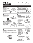
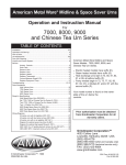
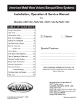
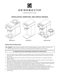
Crathco© Beverage Freezers
SERVICE MANUAL
for MODEL 3361B
TABLE OF CONTENTS
Description......................................... 2
Unpacking........................................... 3
Installation & Assembly.................... 4 - 7
Cleaning & Sanitizing....................... 6 - 9
Control & Product Issues................. 9 - 10
Service & Maintenance..................... 10 - 12
Troubleshooting................................. 13
Addendums....................................... 14 - 22
Prior authorization must be obtained from
Grindmaster Corporation for all warranty claims.
Model 3361B
Grindmaster Corporation
4003 Collins Lane
Louisville, KY 40245 USA
(502) 425-4776
(800) 695-4500
FAX (502) 425-4664
www.grindmaster.com
© Grindmaster Corporation, 2000
PRINTED IN USA
1203 Form # WH-304-03
Part # W0600108
General Description
This unit is specifically designed to freeze pre-mix product supplied from bulk storage containers. The 3361B contains an oil free air compressor used to supply compressed air to push product from bulk storage containers (or gas
driven pumps) to the freezing cylinder. The freezer consists of a freezing cylinder with a rotating internal auger
(dasher) that is belt driven by an electric motor. The auger scrapes frozen product off of the inside of the refrigerated
cylinder. A torque sensing mechanism controls compressor operation to maintain desired product consistency. The
freezer has an air-cooled refrigeration system which only cools the freezing cylinder. A clear, self-closing dispensing
valve is attached to the front of the freezing cylinder. A pressure relief is incorporated into the dispensing valve that
allows excess pressure to be vented. The unit has adjustable consistency and product out indicators.
3361B Description
Unit Part Numbers:
3361B
Overall Dimensions:
Height
26.5 in
67.3 cm
Width
13 in
33 cm
Depth
28.6 in
73 cm
Operating Weight: (approx.)
175 lbs.
80 Kg
Shipping Weight: (approx.)
195 lbs.
88.5 Kg
Compressor:
3/4 Hp
560 W
404a
404a
35 PSI
240 Kpa
60°F
15°C
100°F
37°C
Operating Voltage
115 V
115 V
Current Draw
15 A
15 A
Refrigeration System:
Refrigeration Type
Refrigeration Charge (See data plate)
Expansion valve setting
Ambient Operating Temp:
Minimum Temperature
Maximum Temperature
Electrical Requirements:
Theory of Operation
A self-contained air compressor, within the unit, supplies compressed oil-free air to the outlet connection of the
machine. The air is delivered through the hose to the pre-mix product storage tank(s) or a gas driven product pump.
The air is stored and develops pressure in the product storage tank(s). Pressure above product forces product out
through the hose, to the inlet, to the machines. The product enters the rear of the machine and passes through internal hosing to the freezing cylinder. Product will flow from the storage tank(s) to the freezing cylinder until the pressure has equalized. As long as the tank(s) contain product, product will flow to the freezing cylinder during every dispense period. The air compressor will run and product flow will continue until the pressure has equalized between
the freezing cylinder and the storage tank(s).
The machine contains a flow sensor that differentiates between liquid and air to allow the machine to signal a mix
out condition.
Page 2
Crathco© Beverage Freezers
Unpacking and Inspection
Shipment and Transit
The freezer has been operated and tested at the factory. Upon arrival, the complete
freezer must be thoroughly checked for any damage which may have occurred in transit.
NOTE: A Tip (N) Tell warning device is placed on each shipping carton at the factory. If the
arrow tip is blue, the carton has been tipped in transit. (See Figure A)
THE CARRIER IS RESPONSIBLE FOR ALL DAMAGE IN TRANSIT WHETHER VISIBLE
OR CONCEALED. DO NOT ACCEPT THE SHIPMENT until the freezer has been
checked for damage. Have the carrier note any visible damage on the freight bill. If
concealed damage and/or shortage is found later, advise the carrier within 10 days and
request inspection. The customer must place any claim for damage and/or shortage with
the carrier. Grindmaster Corporation cannot make any claims against the carrier.
Figure A
Loose shipped parts
Part #
W0600108
W0600121
W0631903
W0600159
W0890218
W0340022
W0470076
W0480437
W0480445
W0631230
W0470010
W0600073
W0470019
Name
Manual
Header installation instruction sheet
Sanitizer packets
Warranty card
Drip pan kit
“O” ring #213
Lubricant, Lubri-Film
Plunger, Slush pressure W3361
Handle, valve
Spring, Compression for valve
Pad, Neoprene Black Rubber
Sheet, Caution Rubber Mat
Cleaning Brush, Fas-pin 1/4”
Quantity
1
1
6
1
1
6
1
1
1
1
1
1
1
Safety and Inspection
Safety Precautions
1) Read and understand the operating instructions in this manual thoroughly.
2) Note all warning labels on the freezer.
3) Do not wear loose fitting garments or jewelry that could cause a serious accident.
4) Stay alert at all times during operation.
5) Keep operating area clean.
Do not operate freezer if any excessive noise or vibration occurs. Contact an authorized service agent.
Crathco© Beverage Freezers
Page 3
Installation
Installing Freezer
1) Unbox freezer
a) Remove both side panels and then use a 7/16” socket to remove the 2
bolts at the bottom of the freezer that hold it to the shipping pallet.
b) Cut the wire tie (note red tag) on freezer drive motor. (See Figure B)
c) Leave right side panel (when facing front of freezer) off.
2) Place beverage freezer onto the counter or cabinet on top of the rubber mat
supplied.
3) Attach hose from the product tank(s) to the air supply connection (1/4” SAE
flare). Attach hose from the product tank(s) to the product supply connection
(1/4” SAE flare). (See Figure C)
Figure B
Pre-Mix Dispenser
4) Assemble the dispensing valve assembly.
(See Figure D)
5) Turn “on/off/clean” switch on front of the unit to the
OFF position.
Product
Line
6) Replace freezer right side panels.
Electrical Cord
Locating Freezer
1) Connect freezer to a properly grounded 115-120
VAC, 60 Hz single-phase electrical circuit with a
20-amp (NEMA 5-20R) minimum-rated disconnect
switch (not provided) that is fused at 20 amps
(slow-blow).
Air
Line
Figure C
Product Tanks
! CAUTION: Safe operation of this unit can only be achieved if the
freezer is properly connected to an appropriate grounded, electrical
receptacle that complies with current national safety standards. The
manufacturer cannot be held responsible for damage and/or injury
caused by failure to connect the unit to an appropriate source of
power.
2) A minimum air clearance of 6” is required on both sides of the freezer
during operation. (See Figure E)
! CAUTION: Restricting air flow through the freezer will greatly
reduce the output capacity as this is an “air-cooled” unit. Air is
drawn in to cool the unit through the right side (facing front of freezer) and exhausted through.
Figure D
Figure E
Page 4
Crathco© Beverage Freezers
Attaching Drip Tray
1) The drip tray is mounted on two screws that are located on the lower front of the freezer cabinet.
2) Place the key hole slot of the drip tray support bracket (W0471022) on to these screws and tighten the screws.
3) Angle the back of the drip tray surround bracket into the drip tray support bracket (W0471022) and lower bracket
to lock it into place.
4) Place drip tray onto drip tray surround bracket.
5) Place the louvered drip tray insert into drip tray.
Installing the Product Storage Tank(s)
Check Air Compressor Set Point
1) Remove top plate to the freezer, by removing the four screws on each corner.
2) The recommended operating pressure for the compressor is between 10-25 psi. The remote located product
storage tank(s) will operate safely up to 25 psi. The differential should be 5 to 7 psi.
! CAUTION: The use of excessive pressure (above 25 PSI) will result in relief venting at the product tank(s).
Adjustment:
The scale plate directly indicates the cut-out and differential. The cut-in is calculated by subtracting the differential
from the cut-out:
1) Adjust the range screw until the scale pointer indicates the desired cut-out setting (10-25 psi).
2) Adjust the differential screw until the scale pointer indicates the desired differential setting (5-7 psi). The cut-in
setting equals the cut-out setting less the differential.
Mix Product for the Storage Tanks
For the dispenser to operate properly, the percent of dissolved solids (generally sugar) in the pre-mix product should
be between 11 and 14 as measured by a refractometer (referred to as Brix). If the Brix of the pre-mix product is
below 11 the product will freeze too hard and result in auger freeze-up. If the pre-mix product Brix is above 14 the
product will not freeze quickly and will remain liquid.
NOTE: Brix is the percentage of sugar in the mix. The instrument called a refractometer reads Brix directly. A
refractometer can be purchased from Grindmaster Corporation or most beverage supply companies. The amount of
alcohol affects the performance of the machine. The machine can freeze up to 15% alcohol, however, the product
will be liquid and runny. For best performance, the mix should contain 7-10% alcohol by volume.
Filling the Dispenser
It is recommended that a cleaning and sanitizing procedure be completed before dispensing product.
1) Turn the unit to “CLEAN” after connecting product storage tanks to the unit.
2) Allow the pressure to build in the compressed air system.
3) Product will begin to flow when the pressure begins to build.
Crathco© Beverage Freezers
Page 5
Filling the Dispenser (cont’d)
NOTE: The dispenser contains a flow switch that is activated if the product does not flow in 15 seconds. To reset the
flow switch cycle, turn the power switch to OFF and back to CLEAN.
4) Allow the product to fill the freezing cylinder until pressure equalizes between cylinder and product storage
(approximately 30 seconds).
5) Switch machine to OFF position.
6) Pull relief valve O-ring. (See Figure F)
7) Repeat steps 1 through 6 until the freezing cylinder is full.
NOTE: Unit may need to be vented 2-3 times on initial fill.
Figure F
8) Turn machine ON.
9) Allow 15 to 20 minutes for product to freeze.
Cleaning and Sanitizing
! CAUTION: Freezing cylinder may be under pressure.
All product must be drained from the dispenser and pressure vented. Disconnect power before performing the
following operations.
Removing Product from Barrel
1) Turn freezer switch to OFF.
2) Vent air pressure from storage tank using relief/vent valve on tank lid.
3) Disconnect hose from tank(s) and remove tank lid.
4) Pour remaining product from tanks.
5) Rinse tanks with clean water.
6) Fill tanks with clean water.
7) Replace lid and reconnect hoses.
8) Turn freezer switch to CLEAN.
9) Allow air pressure to build in tanks.
10) Place bucket under product dispensing valve.
11) Pull valve handle and begin dispensing product.
12) Remove product until all of the product in the cylinder is clear water.
13) Allow the freeze cylinder to fill with water. It will be necessary to switch the power to OFF and vent the air from
the barrel by opening pressure relief on dispensing valve.
14) Switch unit from CLEAN to OFF.
Page 6
Crathco© Beverage Freezers
Removing Product from Barrel (cont’d)
15) Relieve pressure from freeze cylinder by pulling relief valve ring.
16) Turn freezer switch back to CLEAN and allow cylinder to fill.
17) Allow unit to run in CLEAN for 5 to 7 minutes.
18) Turn freezer switch to OFF.
19) Drain all water. If flow stops before the cylinder is empty, pull vent (round ring) in valve block and break vacuum.
Cleaning
1) Disassemble the dispensing valve by first removing the dispensing valve pin.
(See Figure G)
2) Push up on the dispensing valve plunger and pull out the dispensing handle.
The plunger assembly complete with spring and “O” Rings can then
be removed as a unit.
3) Remove knobs and carefully remove the freezer dispensing valve assembly.
4) Remove the O-Rings from the plunger assembly and back of the dispensing
valve body.
NOTE: The best way to remove an O-Ring is to first wipe off all of the lubricant
using a clean paper towel. Pinch the O-Ring upward with a dry towel between
your index finger and thumb. When a loop is formed in the O-Ring, roll it out of
the groove with your other thumb. Always remove the O-Ring farthest from the
end of the plunger first. (See Figure H)
Figure G
5) Carefully inspect the O-Rings for wear, nicks or cracking and replace if
necessary.
6) Carefully pull out the auger assembly taking care to avoid damaging the rear
seal assembly at the back of the freezing cylinder.
7) Remove the stationary portion of the shaft seal assembly (ceramic ring and
rubber boot) from the back end of the freezer cylinder. This is accomplished
by reaching into the cylinder and pulling the seal out with your index finger.
(See Figure I)
Figure H
8) Slide the rotary seal off of the auger shaft. Inspect both seal components
carefully for nicks or cracks. Replace seal if defective.
NOTE: To prevent leakage, both surfaces of the seal must be smooth with no chips or cracks.
9) Wash all components in a detergent solution, sanitize and allow to air dry. (See
Figure J) DO NOT WASH COMPONENTS IN A DISHWASHER.
10) Wet the inner rubber lip of the rotary portion of the seal and the back end of
the auger shaft with water. Slide rotary portion of assembly onto the auger
shaft, RUBBER FIRST, with the smooth sealing surface facing toward the
back of the auger.
Crathco© Beverage Freezers
Page 7
Cleaning and Sanitizing (cont’d)
11) Insert the stationary portion of the seal into the grooved rubber boot with
the polished surface facing out (forward), away from the rubber boot.
Lubricate the grooved rubber exterior portion of the boot with silicone lube
and insert it straight back into the recess at the back of the freezing
cylinder, RUBBER FIRST.
NOTE: If the circular portion of the seal is white, make sure that the
groove is toward the rubber (back of freezer).
12) Reassemble the dasher assembly (see Figure K). Insert the larger front and
smaller rear white plastic bearings into dasher, then slip in the stator rod.
Carefully and slowly guide the auger into the freezing cylinder
taking care not to damage the seal assembly. Turn auger shaft until
it engages the square drive coupling.
Figure I
13) Reassemble the dispensing valve assembly. (See Figure G) Be sure to
lubricate o-rings and relief vent before assembling.
14) Thoroughly wash and sanitize all components. Inspect and
lubricate all surfaces of the large O-ring and refit it into the rear of
the valve assembly.
IMPORTANT: Failure to lubricate the large O-Ring can result in product
leakage.
Install the valve assembly on the front studs and tighten knobs until they
are finger tight. Do not use tools to tighten knobs.
Figure J
15) Lubricate the inside bore of valve body with a thin film of food grade
sanitary lubricant. Reinstall the O-rings on the plunger assembly and
lubricate the entire plunger. Reassemble the valve and replace the
retainer pin.
Daily Cleaning of Unit
The exterior of the unit should be cleaned as needed, at the end of the
operating day. Remember to empty and clean the drip tray and drip tray
bracket.
! CAUTION: Course rags, abrasive cleaners, and excessive force can
damage and/or destroy the surfaces of this unit.
Figure K
Sanitizing
1) Disassemble the freezer and disconnect storage tanks following the steps in the previous section.
2) After disassembly, thoroughly scour each part of the freezer in a warm, mild detergent solution including
the inside of the freezing cylinder.
3) Rinse each part with clean water.
4) Prepare a minimum of 2 gallons (7.6 liters) of sanitizing solution (Divorsol CX or equivalent).
NOTE: Add 1.75 ounces (51 ml) of Divorsol CX to 2 gallons (7.6 liters) of 120°F (50°C) water to achieve a
concentration of 500 parts per million. Dip or wipe each part in sanitizing solution and allow them to air dry
on clean paper toweling.
5) Pour 1-1/2 gallons of sanitizing solution into the storage container(s) and reseal. Use remaining solution for
sanitizing small parts.
Page 8
Crathco© Beverage Freezers
Sanitizing (cont’d)
6) Reassemble unit and reconnect storage tanks following assembly instructions.
7) Turn freezer switch to “CLEAN”.
8) Allow the freeze cylinder to fill half way with sanitizer.
9) Turn the freezer switch from “CLEAN” to “OFF”.
10) Open the pressure relief valve located on the freezer dispensing valve to relieve all of the pressure in the freeze
cylinder.
11) Turn the freezer switch to “CLEAN” and allow the freezing cylinder to fill to the relief valve.
12) Allow unit to run in “CLEAN” for 5 minutes.
13) Purge sanitizer from product lines and barrel.
a) Turn freezer OFF.
b) Vent air pressure from storage tank using relief/vent ring.
c) Disconnect hose from tank(s) and remove lid.
d) Pour any remaining sanitizer from tanks.
e) Rinse with clean water or as recommended by your state/local health department.
f) Fill tanks with product.
g) Replace lid and reconnect hoses.
h) Place bucket under product valve.
i) Pull product handle and begin removing sanitizer.
j) Turn freezer switch to CLEAN.
k) Allow air pressure to build in tanks.
l) Dispense product until all sanitizer is purged from the product lines and freeze cylinder.
14) Turn freezer switch to ON and allow 15 to 20 minutes for product to freeze.
Controls and Product Issues
Faceplate Relief Valves
A spring-loaded pressure relief valve maintains a safe pressure in the freezing cylinder. When filling the cylinder the
relief valve acts as a vent to allow the CO2 and air trapped in the freezing cylinder to escape. Venting the freezing
cylinder is essential to obtain proper overrun. The vent is also used to break a vacuum when draining a unit.
Dispensing Valve
! CAUTION: The product on the freezing cylinder is under pressure, open the dispensing valve slowly when
dispensing product.
Consistency Adjustment
NOTE: The following product consistency (thickness) control adjustment procedure requires removal of the right side
panel. It is suggested that a qualified service technician make this adjustment because side panel removal exposes
hazardous moving parts.
WARNING: Do not attempt freezer adjustments until electrical power has been disconnected.
Crathco© Beverage Freezers
Page 9
Consistency Adjustment (cont’d)_
It may become necessary to readjust the consistency setting (thickness) to
compensate for variations between different types of mixes and overrun settings.
1) Disconnect electrical power.
2) Remove right side panel (facing freezer).
3) Use the adjustment screw located on the top, front of the drive motor
mounting bracket to change product thickness. (See Figure L)
• Clockwise for thicker product consistency.
• Counterclockwise for thinner product consistency.
NOTE: It may require up to three 180° turns of this adjusting screw to see a
noticeable change in the product thickness.
Figure L
4) Turn freezer to “ON” and allow it to freeze to desired consistency.
5) Wait 15 to 20 minutes, check product consistency (thickness) and repeat as needed.
6) Reinstall side panel and reconnect power.
Mix Out Light
Red indicator light, located on the front of the freezer, illuminates if the unit runs out of product. When light is on,
the unit will not fill or freeze product.
Service and Maintenance
Servicing Dispensing Valves, O-Rings, and Freeze Cylinder Drive Shaft/Seal Assemblies
NOTE: Dispensing valve “O” Rings should be replaced every 120 days to correspond with quarterly preventative
maintenance visits.
The best technique for removing an “O” Ring is to first wipe off all of the lubricant using a clean paper towel. Pinch
the “O” Ring upward with a dry towel between your finger and thumb. When a loop is formed in the “O” Ring, roll it
out of the groove with your thumb. Always remove the “O” Ring farthest from the end of the plunger first.
(See Figure H)
Lubricating Plunger O-Rings
1) Place freezer in “CLEAN” position.
2) Drain freeze cylinder while purging with water.
3) Turn freezer control switch to the “OFF” position.
4) Vent pressure and drain completely.
5) Remove dispensing valve plunger.
a) Remove valve handle retaining pin.
b) Push plunger up and remove handle.
c) Pull plunger down.
6) Remove “O” Rings and clean “O” Ring grooves.
7) Replace “O” Rings.
8) Lubricate the “O” Rings on the plunger and the area inside of the clear plastic valve body where the plunger “O”
Rings make contact with the valve body using silicone lubricant.
Page 10
Crathco© Beverage Freezers
Lubricating Plunger O-Rings (cont’d)
9) Replace Plunger assembly.
a) Place spring on top of plunger.
b) Place plunger in valve body making sure that the handle opening faces forward.
c) Push up on plunger and replace handle.
d) Insert handle retaining pin.
e) Sanitize unit following instructions in manual.
10) Refill unit following instructions in manual.
NOTE: Plunger o-rings, face plate quad ring, shaft seal set, motor belt, etc. should be replaced at
minimum annually.
Changing Back Lit Sign Merchandiser Bulb
1) Remove the two screws, located on the top of either side of the sign.
2) Lower the metal enclosure that frames the merchandiser insert.
3) Pull merchandiser enclosure down and out.
4) Replace bulb inside.
5) Reassemble.
Cleaning Condenser Coil
1) Turn machine “OFF”.
2) Remove both freezer side panels.
3) Place a wet towel on the inlet side of the condenser (right side facing front of freezer).
4) Use compressed air to blow out condenser coils from the exhaust side of the condenser coil (fan motor side).
NOTE: Follow all health and safety standards.
5) Replace side panels.
Drive Belt Adjustment
! CAUTION: Unplug machine before performing any adjustments. Check the
belt tension quarterly. Proper belt tension is 1/2” deflection measured mid way
between the drive and the driven pulleys (See Figure N). If the deflection is
more that 1/2” adjust the motor height to achieve proper tension using the
following procedure:
1) Unplug the unit and remove the side and rear panels.
2) Locate the motor flange bearings (W0380009) located at each end of the
drive motor. Two bearings support the motor, one on the shaft at each end of
the motor. The bearings are secured to the motor cradle using two Allen
bolts on each bearing.
Figure N
3) Loosen all four bearing Allen bolts.
NOTE: Do not loosen the setscrews that hold the bearing collars to the motor shaft.
4) Lower or raise the motor as needed to achieve proper belt tension. The motor must always be kept level from
front to back.
NOTE: Excessive belt wear and belt noise can occur if the motor is not kept level.
5) Tighten all four Allen bolts down.
6) Align the driven motor pulley with the top driven pulley if needed. Use a straight edge along the top pulley. If the
pulleys are not in alignment, remove the setscrew from the pulley and move either in or out as needed.
NOTE: Use a non-permanent Loc-Tite on the driven pulley setscrew and tighten down on the flat of the motor shaft.
Crathco© Beverage Freezers
Page 11
Parts Replacement Schedule
Part Description
Drive shaft seal
W0340201
Drive shaft
W0451067
Drive belts
W0450209
Scraper blades
on dasher
W1431084
Monthly
Every
3 Months
Every
6 Months
Inspect & replace
if necessary
Annually
Quantities to
be Replaced
Replace
1
Inspect & replace
if necessary
Inspect & replace
if necessary
1
Replace
1
2
Square cut o-ring on valve
body/face plate
W0340055
Inspect & replace
if necessary
1
Front stator flange
bearing
W0430032
Inspect & replace
if necessary
1
Rear stator flange
bearing
W0430024
Inspect & replace
if necessary
1
Dispense valve o-rings
W0340022
Replace
Dispense valve
relief valve
W0650429
Inspect & replace
if necessary
Inlet tube o-rings
W0340011
Condenser
W0200256
Page 12
3
1
Inspect & replace
if necessary
Inspect & replace
if necessary
2
1
Crathco© Beverage Freezers
Troubleshooting Guide
Problem
Probable Cause
Remedy
Machine won’t run (no lights, no motor) • Machine not plugged into wall
receptacle
• Building circuit breaker tripped or
fuse blown
• Switches in wrong position
• Plug machine directly into outlet.
Do not use extension cord.
• Place circuit breaker in the ON
position or replace fuse
• Turn Freezer Switch to ON.
Machine will not freeze
Dasher assembly not installed
Drive belt broken or off pulley
Inadequate airflow
Freezer in CLEAN position
Mix low light on indicating an out of
condition
• Condenser clogged
• Compressor not operating
• Low refrigerant charge
• Install dasher assembly
• Repair or replace
• Allow 6” (15cm) on both sides
• Switch to ON
• Correct out of condition
• Consistency adjuster set too low
• Consistency setting at maximum
• Too much alcohol in product
• Product BRIX level too high
• MIX LOW light on
• Consistency adjuster set too high
• Too little alcohol
• Product BRIX level too low
• Power switch OFF
• MIX LOW light on
• Consistency adjuster set too high
• Drive belt broken or off pulley
• No compressed air
• Product tank connections reversed
• Readjust consistency
• Change to yellow consistency spring
• Correct mix ratio
• Correct mix ratio
• Refill empty product
• Readjust consistency setting
• Correct mix ratio
• Correct mix ratio
• Turn power switch ON
• Refill empty product
• Readjust consistency setting
• Repair or replace
• Check air compressor
• Check product tank connections
Product too soft
Product too thick
Product will not dispense
Leakage from drip tube
Excessive Dispensing Valve leaks
Clicking sound from inside machine
•
•
•
•
•
• Clean condenser
• Check for cause and correct
• Check for leaks, repair and recharge
• Worn out or defective drive shaft seal • Replace seal and then lubricate at
each cleaning
• Worn or defective o-ring(s)
• Replace and lubricate each cleaning
• Excessive pressure from product
• Re-adjust air pressure
delivery system
• Low voltage
• Use dedicated circuit with proper rating
• Extension cord is used
• Connect directly to power source or
use power cord of proper size
Thumping sound from inside machine
• Worn belt
• Product BRIX level too low
• Low alcohol content in product
• Replace belt
• Correct mix ratio
• Check mix
Product does not feed
• Low air pressure
• Product pumps defective
• Carbonator pump defective
• Transformer defective
• Solenoids defective
• Check air compressor operation or air
lines for leaks
• Replace pumps
• Replace pumps
• Replace transformer
• Replace solenoids
• Incorrect installation of dasher
• Improper drive shaft clearance
• Advise careful installation
• Adjust to proper clearance
Premature seal wear
If you still need help, call an authorized dealer in your area or Grindmaster Corporation’s Technical Service
Department. You can reach Technical Service at (800) 425-4776 Monday-Friday, 8:00 AM-6:00 PM Eastern Standard
Time. Please have the model and serial number ready so that accurate information can be given.
Prior authorization must be obtained from Grindmaster Corporation’s Technical Service Department for all
warranty claims.
Crathco© Beverage Freezers
Page 13
Machine Assembly
Page 14
Crathco© Beverage Freezers
Complete Unit Exploded View
ITEM PART NUMBER
10
86807
20
30
40
50
DESCRIPTION
ITEM PART NUMBER
8-32 x 3/8 Sltd. BD HD Screw
160
W0570045
Ballast
W0570206
Terminal, Red Female
W0211086
W0611044
60
83151
70
80
DESCRIPTION
W0610624
10-24 x 1/4 Screw
170
71373
Nylon Screw Anchor
180
W0631610
Front Display Lens
Ballast Cover
190
W0631614
Acrylic Lens
8-32 Nut, Z/P
200
86600
Wire Tie
#8 External Star Washer
210
W0572452
Electrical Box Cover
W0570207
Faston, Blue, Female Fully Insul.
220
W0610127
#8 x 3/4 S.S. TR. HD. Phil. Screw
W0570208
Faston, Blue, Male Fully Insul.
230
W0610265
10-24 x 1/4 Rnd. Hd. Phil. Screw
90
W0570308
Ring Eye, Blue #10
240
W0201194
Baffle, Air, Top
100
W0570901
Mercury Switch
250
W0201130
Top Plate, Pressure S.S.
110
W0570205
Faston, Red, Male Fully Insul.
260
90359
Level Control
120
W0630604
Strain Relief Bushing
270
W0571050
Control Board Support
130
W0572069
Power Cord
280
61304
6-32 x 1/2 Phil. Pan HD Screw
140
W0630802
Cable Tie
290
W0571602
Pressure Comp. Wire Bundle
150
W057290
Light Reflector
290
W0571601SH2
Reference, Wiring Diagram
Crathco© Beverage Freezers
Page 15
Freezer Base Exploded View
ITEM
Freezer Exploded View
Page 16
10
PART
NUMBER
W0201752
Base Pan Assembly
20
W0201001
Compressor Assembly
30
W0201002
Condenser Assembly
40
W0321029
Fan Sub-Assembly
50
W0321026
Drive Motor Assembly
60
W0210083
Frame Assembly
70
W0611410
Rivet, Magna-Lok
80
W0611247
1/4 Int. Tooth Lk. Wshr.
90
W0611074
1/4-20 Hex Nuts
100
W0611082
5/16-18 Flange Nut
110
W0200412
Compressor Spacer
120
W0200413
Compressor Grommet
ITEM PART NUMBER
DESCRIPTION
DESCRIPTION
10
W0610682
5/16-18 x 3/4 Hex Hd. Cap Screw
20
W0611254
5/16 Flat Washer
30
W0611255
5/16 Split Lock Washer
40
W0611086
5/16-18 Hex Nut Z/P
50
W0201191
Suction Line Pressure
60
W0620103
3/8 Copper Couple
70
W0110013
Valve Studs
80
W0611085
5/16-18 S.S. Hex Nuts
90
W0201192
Air Baffle Side Piece
100
W0450053
10” Pulley
110
W0610646
Screw, Set, 5/16-18 x 3/8
120
W0450209
V-belt
130
W0600029
Motor Serial Plate
140
71373
Nylon Screw Anchor
150
W0670008
Trim-Lok Rubber Strip
160
W0600215
ON-OFF-CLEAN Label
170
W0620106
Tee, 1/2 x 3/8 x 3/8 Copper
180
W0201008
Low Side Process Tube
190
W0201006
High Side Process Tube
200
60033
Indicator Light
Crathco© Beverage Freezers
Product Feed Components
ITEM PART NUMBER
Crathco© Beverage Freezers
DESCRIPTION
1
W0200901
Flow Switch
2
W0200160
Pressure Component Support
3
W0471115
Pressure Fill Inlet
4
90758
Check Valve
5
60057
Elbow, Brass
6
W0950035
Pressure Pump
7
W0610345
Screw, 10-32 x 1/4 Truss HD
8
W0340011
O-rings
9
60593
Oetiker Clamp 5/8
10
60591
Braided Soda Hose
11
60591
Braided Soda Hose
12
60591
Braided Soda Hose
13
60591
Braided Soda Hose
14
60591
Braided Soda Hose
15
W0650414
Low Press. Controller (RANCO)
16
W0620006
S.S. Swivel Hose Elbow 1/4 x 1/4
17
W0620007
S.S. Male Hose Elbow 1/4 x 1/4
18
90869
Hose Tee 1/4 x 1/4 x 1/4
19
70451
Male Flare Bulkhead 1/4
20
60054
Valve, Check 1/4 MPT x 1/4 MF
21
W0620003
Female Flare Hose Nipple
22
86600
Wire Tie
23
W0630455
Holder, Wire Tie
24
W0610136
8-32 x 1/4 Pan HD Sltd.
Page 17
Electrical Box Exploded View
ITEM
PART #
DESCRIPTION
ITEM
PART #
DESCRIPTION
10
W0572287
Electrical Box
130
W0610131
8-32 x 1/4 Screw
20
W0570044
Light Socket
140
W0610015
6-32 x 1/4 Slotted Screw
30
W0570235
Terminal Block
150
86827
6-32 Hex Nut Z/P
40
W0630811
Small Capacitor Clip
160
61272
#8 Ground Screw
50
W0570603
Start Capacitor
170
83151
#8 External Star Washer
60
W0570617
Run Capacitor
180
W0630006
Heyco Bushing, 1-1/4
70
W0570638
Compressor Relay
190
86600
Wire Tie
80
W0570651
Sequencer
200
W0631606
Elec. Box Lens
90
W0570924
Toggle Switch
210
W0570043
Fluorescent Bulb
100
W0572032
Transf. Sub-Assy.
220
W0571000
Wire Harness 3311
110
W0572192
Mix Low Sub Assy.
230
W0610132
8-32 x 1/4 Screw
120
83248
6-32 X 1/4 Truss HD.
240
W0572202SH2
Elec. Wiring Ref. Drawing
Page 18
Crathco© Beverage Freezers
3361B Ladder Diagram
ABBREV.
PART
BAL
Ballast
FLA
Florescent Lamp
DM
Drive Motor
CF
Cooling Fan
TS
Toggle Switch
TFMR
Transformer
FS
Flow Sensor
MS
Mercury Switch
T/D
Time Delay Relay
LPC
Low Pressure Controller
AC
Air Compressor
LC
Level Controller
CR
Compressor Relay
RC
Run Capacitor
SC
Start Capacitor
COMP
Compressor
MOL
Mix Out Light
Crathco© Beverage Freezers
Page 19
3361B Freezer Electrical Schematic
1
2
3
4
5
7
8
9
10
11
12
13
14
17
18
19
21
22
23
24
25
26
27
Yellow Wire 18 GA.
Black Wire 16 GA.
White Wire 16 GA.
Orange Wire 16 GA.
Orange Wire 16 GA.
Black Wire 14 GA.
Black Wire 14 GA.
Red Wire 16 GA.
Red Wire 16 GA.
Yellow Wire 18 GA.
Red Wire 16 GA.
Red Wire 16 GA.
1 White Wire 1 GA.
Green Wire 16 GA.
White Wire from Transformer
Black Wire from Transformer
Red Compressor Wire
Black Compressor Wire
Yellow Compressor Wire
Yellow Wire 22 GA.
Yellow Wire 22 GA.
White Wire 16 GA.
Black Wire 16 GA
Page 20
28
29
30
32
33
34
49
50
57
61
63
65
66
68
69
73
74
75
76
77
78
79
Black Wire from Power Cord
White Wire from Power Cord
Green Wire from Power Cord
White Solid Core 18 GA.
Black Solid Core 18 GA.
Black Solid Core 18 GA.
White Wire 16 GA.
Black Wire 16 GA.
Blue Wire 16 GA.
Yellow Wire 18 GA.
Black Wire 18 GA.
Black Wire 16 GA.
White Wire 18 GA.
Black Wire from Solenoid
Black Wire from Solenoid
White Wire from Pump
White Wire 18 GA.
Black Wire 18 GA.
Yellow Wire 18 GA.
Yellow Wire 18 GA.
Black Wire 18 GA.
White Wire 18 GA.
72
71
70
56
55
48
47
46
45
44
43
42
41
40
39
38
37
36
W0650050
Level Control Board
W0200901
Flow Switch
W0950035
Pressure Pump
W0650414 Low Pressure Controller
60033
Light, Red
057.0924
Switch
057.0043
Florescent Light Bulb
057.0044
Light Socket
057.0045
Core & Coil Ballast
063.0801
Tie Wraps
057.2068
Power Cord
057.2192
Low Mix Sub-Assy
057.0604
Run Capacitor
057.0603
Start Capacitor
057.0235
Terminal Block
057.0651
Time Delay Relay
057.2032 Transformer Sub-Assembly
057.0638
Compressor Relay
Crathco© Beverage Freezers
Refrigeration Components
ITEM
PART #
DESCRIPTION
1
W0650501
Access Valve
2
W0200310
Drier/Cap Tube Assembly
3
W0201191
Suction Line
4
W0200123
Compressor
5
W0200256
Condenser
6
W0201009
Hot Gas Line
7
W0620112
3/8” Copper Elbow
8
Evaporator Line
9
Suction Line
10
W0620107
90 Deg. Street Elbow
11
W0201151
3/8” Cond. Connection
12
W0620103
3/8” Copper Couple
13
W0201152
5/16 x 3/8 Red/ Couple
14
W0620114
3/8” Copper Tee
15
W0201006
High Side Process Tube
16
W0620106
1/2 x 3/8 x 3/8 Copper Tee
17
W0201008
Low Side Process Tube
Crathco© Beverage Freezers
Page 21
Refrigeration Schematic
Page 22
Crathco© Beverage Freezers
Notes
Crathco© Beverage Freezers
Page 23
Grindmaster® Coffee Grinders and Brewers • Espressimo® Espresso Machines • Crathco® Hot Beverage Dispensers
Crathco® Cold and Frozen Beverage Dispensers • American Metal Ware® Coffee and Tea Systems
Tel (502) 425-4776 • Fax (502) 425-4664 • 1-800-695-4500
P.O. Box 35020 • Louisville, KY 40232 • USA
www.grindmaster.com • email: [email protected]