1
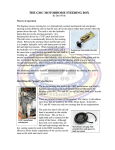
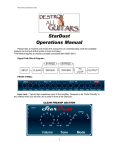
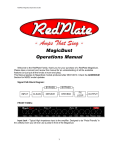
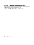
TABLE OF CONTENTS IMPORTANT SAFETY INSTRUCTIONS ................................................................................... 3 WARNINGS .................................................................................................................. 3 DANGER ...................................................................................................................... 3 IMPORTANT REQUIREMENTS ............................................................................................. 4 LOCATION AND SUPPORT ................................................................................................. 4 LOCATION DIMENSIONS .................................................................................................... 5 ATTACHING THE SEAT BACK CUSHION ............................................................................... 6 SEAT BACK ATTACHMENT.............................................................................................. 6 INSTALLING THE FLOOR MOUNTING BRACKETS.................................................................... 7 INSTALLING AND REMOVING THE SHELLS ............................................................................ 8 REMOVING AND REPLACING DRAIN KNOB........................................................................... 9 REMOVING AND REPLACING DRAIN STRAINER .................................................................... 9 DISASSEMBLING AND REMOVING CLEAN TOUCH COMPONENTS .......................................... 10 WIRED FOR SOUND OPTION – HARD WIRED FOR SOUND ................................................... 11 WIRED FOR SOUND OPTION – EQUIPPED WITH SPEAKERS IN NECK PILLOW......................... 11 REPLACEMENT PARTS.................................................................................................... 12 FULL ASSEMBLY ......................................................................................................... 12 BASIN ASSEMBLY ....................................................................................................... 14 INLET COVER AND RELATED PARTS .............................................................................. 15 MOTOR ASSEMBLY ..................................................................................................... 15 DRAIN ASSEMBLY ....................................................................................................... 16 SEAT MOVEMENT ....................................................................................................... 16 POWER DRAIN PUMP ASSEMBLY .................................................................................. 17 HIGH CAPACITY PUMP ASSEMBLY ................................................................................ 17 GENERAL TROUBLESHOOTING GUIDE .............................................................................. 18 HISTORY AND NOTES ..................................................................................................... 19 Doc ID: 33080003 Technical Support: 800-626-6912 Rev: B Page 2 IMPORTANT SAFETY INSTRUCTIONS When using an electrical appliance, basic precautions should always be followed, including the following: Read all instructions before using this appliance. WARNINGS To reduce the risk of burns, fire, electric shock, or injury to persons... Use this appliance only for its intended use. Do not use attachments not recommended by the manufacturer. Never operate this appliance if it has a damaged cord or plug, if it is not working properly, if it has been dropped or damaged, or dropped into water. Never drop or insert any object into any opening. Do not use outdoors. Do not operate where aerosol (spray) products are being used or where oxygen is being administered. Excessive water temperature is dangerous and should be checked before use. Maximum operating water temperature should not exceed 105° F (41° C) and the maximum supply water temperature should not exceed 120° F (49° C). Always enter and exit the pedicure spa slowly and carefully. Never bring or operate any electrical devices into or near the pedicure spa. This pedicure spa has a weight capacity of 350 pounds. Do Not Crush – Avoid sharp folds. Do not stand on or in appliance. Use only while seated. Keep children away from extended foot support. Connect this appliance to a properly grounded outlet only. See Grounding Instructions within the install manual. DANGER Never use pins or other metallic fasteners with this appliance.• Carefully examine the covering before each use. Discard the appliance if the covering shows any sign of deterioration, such as checking, blistering, or cracking. Keep electrical components dry – Do not operate in a wet or moist environment. Note: Always verify maximum water temperatures with your local & state codes. SAVE THESE INSTRUCTIONS Doc ID: 33080003 Technical Support: 800-626-6912 Rev: B Page 3 IMPORTANT REQUIREMENTS EUROPEAN TOUCH requires that you contact a local, licensed plumber and licensed electrician to install your new pedicure spa. Installation must be in compliance with all your local and state building codes. Your pedicure spa cannot operate efficiently or safely unless it is provided with adequate electrical power, sufficient water pressure, proper water temperature, and required drainage capabilities. Contact your local building inspector for information and local code compliance procedures that need to be followed when having your pedicure spa installed. Subsequent inspections and approvals that may be required are the responsibility of the purchaser. (See limited warranty regarding incidental or consequential exclusions – page 2). Note: Failure to comply with federal, state or local codes and ordinances will result in warranty being null and void. WARNING: Shells & front plate MUST be removed prior to moving the Rinato XL Spa. Spa shipping configuration Spa appearance prior to moving into place LOCATION AND SUPPORT Select a level location. The floor structure beneath the pedicure spa must be capable of supporting the occupied pedicure spa. For the seat back to fully recline, the pedicure spa base must be mounted 17 inches from the wall as shown: Doc ID: 33080003 Technical Support: 800-626-6912 Rev: B Page 4 LOCATION DIMENSIONS Doc ID: 33080003 Technical Support: 800-626-6912 Rev: B Page 5 ATTACHING THE SEAT BACK CUSHION Make sure all parts are removed from box before discarding. If any parts are missing, contact EUROPEAN TOUCH within 30 days of delivery date for replacement at 1-800-626-6912. The Rinato XL Spa ships with its bottom cushion already installed. Note: 2 people are required to perform the following instructions. SEAT BACK ATTACHMENT 1. Place Cushion in place in front of frame bracket and align holes of the cushion frame and the seat frame. 2. Screw the Shoulder Bolts (2) into the side of the frame into the frame of the seat until tight. Do not over tighten. Shoulder Screws 3. Install the Clevis Pin through the hole in the Actuator Motor Arm and Clip as shown at left. Hitch Pin Clevis Pin 4. Ensure that Remote Cords are not pinched between cushion and frame bracket. Ensure the Hitch Pin does not hit nut when chair is rotated. Doc ID: 33080003 Technical Support: 800-626-6912 Rev: B Page 6 INSTALLING THE FLOOR MOUNTING BRACKETS All Rinato XL Spas installed with gravity drain and / or hard piped to hot and cold supply lines MUST be anchored to the floor. 1. Adjust all 4 leveling feet until unit is stable and level. 2. Place the floor mounting brackets on one of the front feet and on the rear foot of the opposite side. 3. Mark and drill hole in floor for each bracket and install 3/8” floor anchor in each hole. Note: Moving spa with flexible hose connected may cause strain and cause leaks. Doc ID: 33080003 Technical Support: 800-626-6912 Rev: B Page 7 INSTALLING AND REMOVING THE SHELLS To install the shells on your spa follow the instructions below: 1. Slightly lift side panel into place on spa frame. 2. Align the magnets on the frame legs with matching brackets found on the inside of the side panel. There is one set on each leg. 3. The side panel should fit under lip of basin as shown. 4. Align the thumbscrew holes located under cushion and tighten thumbscrew on each side. 5. Install the front plate by aligning pegs to matching holes and pressing into place. Doc ID: 33080003 Technical Support: 800-626-6912 Rev: B Page 8 REMOVING AND REPLACING DRAIN KNOB Check your state and local regulations for cleaning procedures. Links to your state boards can be found on our web site, at www.europeantouch.com. Refer to the Owner’s Manual “Cleaning and Disinfecting Pedicure Equipment” (page 16) for cleaning recommendations. To remove the chrome drain handle, loosen the set screw in the slot on the drain handle and slip off chrome handle from chrome handle post. Drain handle removed. Drain plunger removed. REMOVING AND REPLACING DRAIN STRAINER Lift the pop-it as shown above. Doc ID: 33080003 Technical Support: 800-626-6912 Lift the strainer as shown above. Reverse the steps to replace Rev: B Page 9 DISASSEMBLING AND REMOVING CLEAN TOUCH COMPONENTS Check your state and local regulations for cleaning procedures. Links to your state boards can be found on our web site, at www.europeantouch.com. Refer to the Owner’s Manual “Clean Touch™ Pipe-Free® Spa - Cleaning and Disinfecting Procedures,” for cleaning recommendations. Please note that the longer nose of the Clean Touch Assembly with the arrow, as indicated by the arrow above, is pointing away from the drain and towards the footrests. To remove the Clean Touch Assembly, move the longer nose in the direction as shown. Separate Clean Touch inlet cover from base by twisting counter-clockwise. Remove the impeller by lifting from the basin. To reassemble, follow instructions in reverse order. Doc ID: 33080003 Technical Support: 800-626-6912 Rev: B Page 10 WIRED FOR SOUND OPTION – HARD WIRED FOR SOUND 1/8” (3.5mm) Headphone Jack Plug in Headphones or Portable Speakers Plug Audio/Visual Device into Spa using provided cord. When not in use, stow away the end of the headphone plug cable in the Massage Remote pocket. WIRED FOR SOUND OPTION – EQUIPPED WITH SPEAKERS IN NECK PILLOW Audio heard from speakers located in neck pillow Plug Audio/Visual Device into Spa using provided 1/8” (3.5mm) cord. Doc ID: 33080003 Technical Support: 800-626-6912 Rev: B Page 11 REPLACEMENT PARTS FULL ASSEMBLY Doc ID: 33080003 Technical Support: 800-626-6912 Rev: B Page 12 ITEM NO PART NO DESCRIPTION QTY 1 30022100 FRAME BASE CT 1 2 3015200X(0,1) 3 15130027 SCREW 1/4-20 X 1/2 SOCKET HEAD CAP 6 4 30010221 GASKET BUTTON SWITCH 1 5 30042000 SWITCH MEMBRANE ON/OFF TWO POSITION CT 1 PDP & HCPDP 6 30042001 SWITCH MEMBRANE ONE POSITION ON/OFF CT 1 Floor Drain 7 2515200X(5,6) 8 330100X(0,2-4,9) 9 3301001X(0,2-4,9) 10 15130009 SCREW THUMB 1/4-20 X 3/4 2 11 30151202 DRAIN KIT HARD PLUMB ASSY 1 12 30020100 BELLY PAN CT 1 13 30020102 COVER SPLASH 1 14 30040400 CONTROL BOX 1 15 15040013 TRANSFORMER VIBRATION MASSAGE 1 16 06040220 TRANSFORMER STEP-DOWN 2202/240V 50/60HZ 1 17 14040422 CONTROL BOX DRAIN PUMP PIPE-FREE 1 18 30152015 SUBASM HANNING MOTOR CT 1 19 15130000 BULKHEAD FTG FOR CHECK VALVE 2 20 25132013 BULKHEAD FITTING 3/4IN THREAD 3/4IN BARB 1 21 15130016 CHECK VALVE 4 22 30152009 SUBASM PDP HC RINATO CT 1 HCPDP 23 30152004 SUBASM PDP STANDARD CT 1 PDP 24 3316130X(0-4,9) 25 12040000 REMOTE CONTROL W AND 1 26 15040400 REMOTE CONTROL SEAT MOVEMENT JG 1 27 33010021 SHROUD SEAT COVER XL 1 28 33020000 SEAT FRAME ASSEMBLY XL 1 29 3015263X(0,3-6,9) 30 33010020 Doc ID: 33080003 SUBASM BASIN CT (PLATINUM, PEARL) SUBASM FRONT PLATE (PLATINUM, PEARL) PANEL BODY XL LEFT (CINNABAR, GRAPHITE, BLACK, ALMOND, CUSTOM) PANEL BODY XL RIGHT (CINNABAR, GRAPHITE, BLACK, ALMOND, CUSTOM) CUSHION SET RINATO XL (SAHARA, BARK, INDIA INK, SAGE, HARMONY, CUSTOM) SUBASM HEADREST SPEAKER (INDIA INK, SAHARA, BARK, SAGE, HARMONY, CUSTOM) ARM REST ASSEMBLY XL Technical Support: 800-626-6912 NOTE: 1 1 1 1 PDP & HCPDP PDP & HCPDP 1 1 Integral Sound Option 2 Rev: B Page 13 BASIN ASSEMBLY ITEM NO PART NO DESCRIPTION QTY ITEM NO 1 15040012 TRIM LOCK CHROME BASIN 1 12 1 13 2 3101022X BASIN PF CT DROP IN W-TRIM STYLE PART NO DESCRIPTION BOLT HEX HEAD M8-125 X 20MM SS W ASHER #10 SPLIT LOCK 18-8 02020000 SST NUT 10-32 NYLON INSERT SS 12130054 LOCK GASKET BUSHING PLATE.062 25002000 NEOPRENE 25132004 QTY 2 4 (0,1) (PLATINUM,PEARL) 3 30150001 SUBASM SHOWER SPRAYER CT 1 14 4 25132100 FAUCET CARTRIDGE DUAL 1 15 5 25022014 ESCUTCHEON SPRAYER BRASS 1 16 12000216 I-GLIDE BUSHING LEG REST ARM 2 6 30152002 SUBASM FOOT REST 2 17 15000006 GASKET DRAIN ASSEMBLE 3 7 25152016 BUSHING FOOTREST 2 18 25022003 BUSHING SUPPORT PLATE RIGHT 1 8 01030001 DECAL - DO NOT STAND IN BASIN 1 19 25022002 BUSHING SUPPORT PLATE LEFT 1 9 03130012 W ASHER AIR BLEED FENDER 2 20 30020209 STOP FOOTREST RINATO 2 10 14130006 W ASHER LOCK SPLIT 3/8 SS 2 21 25022001 FOOTREST MOUNT PLATE 1 11 06130070 SCREW 10-32 X 1/2 FH PHIL MACH 2 22 30020200 CAP 1/4" THREAD 1 Doc ID: 33080003 Technical Support: 800-626-6912 Rev: B 4 2 Page 14 INLET COVER AND RELATED PARTS ITEM NO 1 2 PART NO DESCRIPTION 300102XX COVER INLET HOUSING CT (07,14) (PEARL,PLATINUM) QTY 1 300102XX HOUSING INLET ASM DUAL LOCK 1 (40,41) (PLATINUM, PEARL) 3 30010203 IMPELLER CT 4 30010030 PLATE MOUNTING DUAL LOCKING 1 5 30010208 1 1 GASKET INLET HOUSING CT MOTOR ASSEMBLY Doc ID: 33080003 ITEM NO PART NO DESCRIPTION QTY 1 30040200 MOTOR HANNING FANLESS 1 2 30010202 SHAFT IMPELLER 1 3 14000001 SEAL TOP PIPE FREE 1 4 30010209 GASKET MOTOR FACE PLATE 1 5 14000001 SEAL BOTTOM PIPE FREE 1 6 30010206 SHIELD DRIP NG 1 7 14040265 SENSOR FOOTPLATE DETECTION 2 8 30010229 FACEPLATE MOUNTING W-TBOLTS 1 9 30010226 SHROUD MOTOR 1 10 30041400 W IRE GROUND YELLOW-GREEN 1 11 12010584 CABLE TIES (NOT SHOWN) 4 12 02020000 W ASHER #10 SPLIT LOCK 4 13 12130003 SCREW #10-32x .50 PH 4 14 30040403 CABLE DOUBLE HARNESS SENSOR 1 15 12010219 W ASHER NEO 1-1/4OD X 1/2ID X 1/8TK 1 16 30040401 1 Technical Support: 800-626-6912 CABLE W ATER MOVEMENT Rev: B Page 15 DRAIN ASSEMBLY ITEM NO PART NO DESCRIPTION QTY 1 30010225 SHOE W ASTE 1 2 30010222 OVERFLOW ASM 1 3 30020202 STRAINER DRAIN 1 4 30010224 TUB LOCK GASKET 1 5 30020203 LOCKING PLATE OVERFLOW 1 6 30020205 HANDLE CONTROL 1 7 30020201 THREADED W ASTE BOLT 1 8 30020204 NIPPLE INTERNAL THREAD 1 9 30020206 CABLE DRAIN 1 10 30020208 STOPPER (CHROME) 1 11 30010227 GASKET STOPPER RINATO 1 SEAT MOVEMENT ITEM NO PART NO DESCRIPTION QTY 1 33020002 FRAME SEAT LOWER XL 1 2 33020301 PLATE SEAT MOUNT XL 1 3 33021300 SWIVEL XL 3 4 33020300 PLATE SEAT XL 1 5 01130005 NUT LOCK THIN 5/16-18 4 6 03130043 BOLT CARR 5/16 X 1/2 4 7 06130009 HITCH PIN 2 8 06130008 CLEVIS PIN 1-1/2 IN X 3/8 IN DIAMETER 2 9 03130031 SEAT RAIL WITHOUT LATCH 2 10 15040405 LINEAR DRIVE 50MM BACK 1 11 15040405 LINEAR DRIVE 140MM SEAT 1 12 15040409 CONTROL BOX SEAT MOVEMENT 1 Doc ID: 33080003 Technical Support: 800-626-6912 Rev: B Page 16 POWER DRAIN PUMP ASSEMBLY ITEM NO PART NO DESCRIPTION QTY ITEM NO PART NO DESCRIPTION QTY 1 14040477 CORD POWER DRAIN PUMP 1 9 12010177 3/4 CLEAR BRAIDED HOSE 1 2 08040005 PUMP PDP 110V DPO 40 1 10 12130091 #10 HOSE CLAMP 2 3 12010235 CONNECTOR 1.5IN X 1.25IN 1 11 14010113 COUPLER 1" IN 1 4 30010218 COUPLER 1.5" TO 1.5" W-CLAMPS 1 12 12130041 BOLT 1/4-20 X 3/4 HEX 1 5 30010217 1 13 25132005 W ASHER M8 1 6 25132008 ADAPTER 1 IN TUBE TO 1 IN PIPE 1 14 30020103 BRACKET PDP SHORT 1 7 25132006 CHECK VALVE 1IN FNPT 1 15 12130048 NUT 1/4-20 NYLON CAP LOCK 8 25132007 ADAPTER 3/4 IN TO 1 IN 1 DRAIN W ASTE EXTENSION 1 HIGH CAPACITY PUMP ASSEMBLY ITEM NO PART NO DESCRIPTION QTY 1 12020192 1/2 FPT X 1/2 MPT 90 Elbow 1 2 30010223 Drain Waste Extension For HC PDP 1 3 30010218 Coupler 1.5" To 1.5" With Clamps 2 4 06010024 SCS 1/2 X 1/2 FPT Coupler 1 5 08010004 Nipple PVC Ftg PDP 1 6 15130028 Bushing Reducing 1 1/4 In X 1/2 In 1 7 15130022 Hose 48 In Rubber Platino 1 8 30020104 Bracket High Capacity Pump 1 9 08040001 Pump PDP 110v 1 10 15130029 Clamp Tube 6 1/2 In 1 Doc ID: 33080003 Technical Support: 800-626-6912 Rev: B Page 17 GENERAL TROUBLESHOOTING GUIDE PROBLEM DESCRIPTION RESOLUTION REFERENCE (1) Verify unit is plugged in to live wall outlet Verify motor is plugged in to gray control box (2) Verify fuse in the gray control box is in tact On/Off Button Not Blinking (3) Verify the wires to the button are not cut No Water Remove clean touch assembly and verify the impeller Impeller not in place (4) Movement is in place (5) 6) Ensure that the clean touch assembly is properly On/Off Blinking Power Button attached to the basin (6) 7) Ensure that the black sensor underneath the front of (7) the basin is plugged in 1. Seat Back 8) Ensure air connections are in tact. Chair a. Air Massage controls not Ensure handset is on. (8) Functions working. Ensure compressor is on. are not (9) 9) If the remote lights up, but functions do not work, 2. Chair movement not working contact European Touch Customer Service. responding. 10) Make sure plunger is set tall enough to allow water to (10) pass through. Chair does not drain properly 11) Check for plugged drain and clear if clog is found. having only the standard (11) Water Not drain, (No PDP). 12) If the LED light is On and the pump is heard, check for Draining (12) plugged drain and clear if clog is found. Chair does not drain properly 13) If the LED light is On and the pump is NOT heard, (13) verify drain pump is properly connected to the black having a PDP. control box. 14) Verify water supply is On. (14) Water not The water sprayer is not 15) Check for loose water connections under the basin and working or working or very little water (15) at the rear of the chair. pressure is comes out of the sprayer 16) Unscrew the sprayer head from its hose and verify (16) low head screen is clear. (17) 17) Check drain plunger for tears in rubber gasket. Basin The basin continually loses 18) Verify drain plunger height is correct and bolt below (18) Losing water either quickly or over plunger is tight. Water long period of time (19) 19) Verify drain strainer is tight. CONTACT EUROPEAN TOUCH TECHNICAL SUPPORT AT 1-800-626-6912 WITH ANY ISSUES THAT CANNOT BE RESOLVED USING THIS TROUBLESHOOTING GUIDE. 1) 2) 3) 4) 5) Doc ID: 33080003 Technical Support: 800-626-6912 Rev: B Page 18 HISTORY AND NOTES Doc ID: 33080003 Technical Support: 800-626-6912 Rev: B Page 19 EUROPEAN TOUCH 8301 W. Parkland Court Milwaukee, WI 53223 Phone Number: Toll Free: Fax: Web Site: Email: 414-357-7016 800-626-6912 414-357-6360 www.europeantouch.com [email protected]