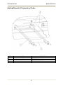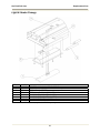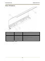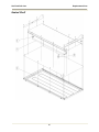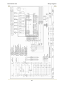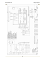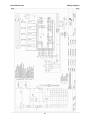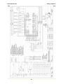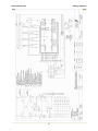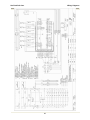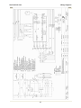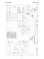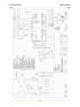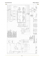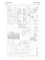
1
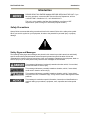
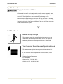
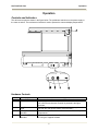
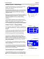
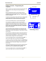
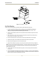
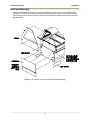
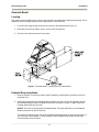
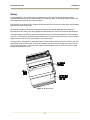
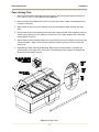
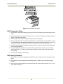
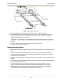
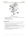
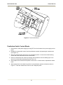
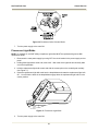
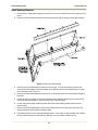
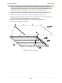
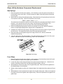
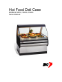
Hot Food Deli Case
MODELS WDCG, SSWG, CSWG
Service Manual
Warranty Information
LIMITED ONE YEAR WARRANTY
BKI (The “Company”) warrants to the original purchaser/user, that at time of shipment from the Company
factory, this equipment will be free from defect in materials and workmanship. Written notice of a claim
under this Warranty must be given within ONE YEAR AND THREE MONTHS from date of shipment from
the factory. Defective conditions caused by abnormal use or misuse, lack of maintenance, damage by
third parties, alterations by unauthorized personnel, acts of God, failure to follow installation instructions
or any other events beyond the control of the company will NOT be covered under Warranty. The
obligation of the Company under this Warranty shall be limited to repairing or replacing (at the option of
the company) any part which is defective in reasonable opinion of the Company. The user will have the
responsibility and expense of removing and returning the defective part to the Company as well as the
cost of reinstalling the replacement or repaired part.
IN NO EVENT SHALL THE COMPANY BE LIABLE FOR LOSS OF USE, LOSS OF REVENUE OR
LOSS OF PRODUCT OR PROFIT OR FOR INDIRECT OR CONSEQUENTIAL DAMAGES INCLUDING
BUT NOT LIMITED TO, FOOD SPOILAGE OR PRODUCT LOSS. WARRANTY DOES NOT COVER
GLASS BREAKAGE. THE ABOVE WARRANTY IS EXCLUSIVE AND ALL OTHER WARRANTIES,
EXPRESS OR IMPLIED, ARE EXCLUDED INCLUDING THE IMPLIED WARRANTIES OF
MERCHANTABILITY AND FITNESS FOR A PARTICULAR PURPOSE. THIS WARRANTY SHALL
APPLY ONLY WITHIN THE CONTINENTAL UNITED STATES, ITS TERRITORIES, AND
POSSESSIONS AND IN CANADA.
LIMITED NINETY DAY LABOR WARRANTY
All labor necessary to repair or replace factory defective parts will be performed, without charge, to the
end user, by service personnel of a BKI Authorized Distributor during the first ninety days after the date of
installation of the new equipment.
Replacement parts: Any appliance replacement part, except lamps and fuses, which proves to be
defective in material or workmanship within 90 days from date of original installation will be repaired or
replaced without charge F.O.B. Factory, Simpsonville, S.C. or F.O.B. authorized distributor.
Hot Food Deli Case
Table of Contents
Table of Contents
Table of Contents........................................................................................................................................ 1
Introduction ................................................................................................................................................. 2
Safety Precautions.................................................................................................................................... 2
Operation ..................................................................................................................................................... 5
Controls and Indicators............................................................................................................................. 5
Preheating................................................................................................................................................. 8
Temperature Adjustment .......................................................................................................................... 8
Operational Guidelines ............................................................................................................................. 8
Unit Shutdown........................................................................................................................................... 8
Installation ................................................................................................................................................... 9
Unpacking and Handling........................................................................................................................... 9
Floor Model ............................................................................................................................................... 9
Pedestal Model ....................................................................................................................................... 12
Counter Model ........................................................................................................................................ 13
Wiring...................................................................................................................................................... 14
Case Joining Trim................................................................................................................................... 15
Case Divider Glass ................................................................................................................................. 16
Maintenance .............................................................................................................................................. 17
Scheduled Maintenance ......................................................................................................................... 17
Well Numbering Convention ................................................................................................................... 18
Troubleshooting ...................................................................................................................................... 18
Control Service.......................................................................................................................................... 20
Accessing Control Panel......................................................................................................................... 20
Electrical Component Replacement ....................................................................................................... 20
Glass Lift-Up Hardware Component Replacement ................................................................................ 31
Replacement Parts.................................................................................................................................... 34
Control Panel .......................................................................................................................................... 34
Pushbutton Switches and Terminal Block .............................................................................................. 35
Control Display........................................................................................................................................ 36
Heating Elements & Temperature Probes.............................................................................................. 37
Light & Heater Canopy ........................................................................................................................... 38
Glass Lift Hardware ................................................................................................................................ 39
Heated Shelf ........................................................................................................................................... 40
Wiring Diagrams....................................................................................................................................... 42
1
Hot Food Deli Case
Introduction
Introduction
PLEASE READ THIS ENTIRE MANUAL BEFORE SERVICING THE UNIT. If you
have any questions, contact the BKI Technical Service Department, toll free:
1-800-927-6887. Outside the U.S., call 1-864-963-3471.
This unit is to be sealed to the floor after installation to conform to NSF
requirements. (Dow Corning RTV #732 Multi purpose Sealant.)
Safety Precautions
Always follow recommended safety precautions listed in this manual. Below is the safety alert symbol.
When you see this symbol on your equipment, be alert to the potential for personal injury or property
damage.
Safety Signs and Messages
The following Safety signs and messages are placed in this manual to provide instructions and identify
specific areas where potential hazards exist and special precautions should be taken. Know and
understand the meaning of these instructions, signs, and messages. Damage to the equipment, death or
serious injury to you or other persons may result if these messages are not followed.
This message indicates an imminently hazardous situation which, if not avoided,
will result in death or serious injury.
This message indicates a potentially hazardous situation, which, if not avoided,
could result in death or serious injury.
This message indicates a potentially hazardous situation, which, if not avoided,
may result in minor or moderate injury. It may also be used to alert against unsafe
practices.
This message is used when special information, instructions or identification are
required relating to procedures, equipment, tools, capacities and other special
data.
2
Hot Food Deli Case
Introduction
Specific Precautions
Equipotential Ground Plane
When a high current flows through a conductor, differences in potential appear
between the conductor and nearby metallic surfaces near the appliance. As a
result, sparks may be produced between the appliance and surrounding metal
surfaces. These sparks could cause serious injury, damage, or fire.
BKI provides an Equipotential ground terminal for the connection of a bonding
conductor after the installation of the appliance per lEC60417-1. This terminal is
located on the inside of the Power Entry Supply box near the Earth connection
and is marked with this symbol.
Safe Work Practices
Beware of High Voltage
This equipment uses high voltage. Serious injury can occur if any
untrained or unauthorized person installs, services, or repairs this
equipment. Advise your customer to always use an Authorized
Service agent to Service this Equipment
Your Customer Should have an Operators Manual
The operators manual is an important part of this equipment. Your
customer should keep it near for easy access.
If your customer needs a replacement operators manual, contact:
BKI
Technical Services Department
P.O. Box 80400
Simpsonville, S.C. 29680-0400
Or call toll free: 1-800-927-6887
Outside the U.S., call 864-963-3471
3
Hot Food Deli Case
Introduction
Safety Labels Must be Clean and in Good
Condition
Make sure all safety labels are in place, clean and in good condition.
Replace any damaged or missing safety labels.
If you need new safety labels, contact:
BKI
Technical Services Department
P.O. Box 80400
Simpsonville, S.C. 29680-0400
Or call toll free: 1-800-927-6887
Outside the U.S., call 864-963-3471
4
Hot Food Deli Case
Operation
Operation
Controls and Indicators
The deli case controls are shown in the figure below. The pushbutton switches turn the power supply to
the case on and off. The touchscreen interface is used to operate the case and display temperatures.
Hardware Controls
Item #
1
2
3
4
5
Description
Power OFF Switch
Power ON Switch
Main Power Isolator
Light
Analog Touchscreen
Interface
Controller RS-232
Interface
Function
Depressing the switch turns power OFF to the entire unit.
Depressing the switch turns power ON to the entire unit. When the
unit is ON the touchscreen controller is powered & the lights
illuminate.
This light illuminates to indicate that power is being applied to the
unit from the main power isolator (circuit breaker).
Used for the operation of the unit and to measure & record product
temperatures.
Allows user to download saved product temperatures to a laptop
PC using the supplied software.
5
Hot Food Deli Case
Operation
Software Controls - Default Screen
Menu Button
The Default Screen appears on the touchscreen during normal
operation. The screen shows the menu button and a
representative temperature.
The representative temperature does not correspond to the
internal temperature of the food products in the case. This
temperature is only an indication that the case is operating
properly and heating.
When the unit is first powered up the representative temperature
will be approximately room temperature. As the unit preheats the
representative temperature will rise. The representative
temperature will stabilize when the unit reaches operating
temperature.
Default Screen
Lower Right
Lower Left
The representative temperature should be approximately the
same from day to day when the unit is in operation. A significant
change in this temperature without changing any of the
temperature settings of the unit may indicate a problem with the
unit. A qualified BKI service representative should be contacted.
Software Controls - Viewing Settings
Exit Button
The current heater settings can be viewed by touching the Menu
Button [M] on the Default Screen. The Menu Screen will then be
displayed.
To view the current settings for either Well Temp or Upper Heater
touch the appropriate button on the Menu Screen. The View
Setting Screen for the selected heaters will be displayed.
To return to the Default Screen, touch the Exit Button [X].
Menu Screen
If the controller is configured to control each well position
independently the View Setting Screen as shown at right will be
displayed. Use the left and right arrows to display the heater
setting for the various well positions of the unit. The progress bar
gives a visual representation of the well location for which the
setting is being displayed.
Progress Bar
The current heater setting is displayed on the right side of the
screen. The setting is a numeric value between 1 and 10 where
10 is the hottest setting.
If the controller is configured to control all of the well positions at
the same setting, the progress bar will be solid and the left and
right arrows will not be displayed. The setting shown will be for
the heaters at all of the well positions.
To return to the Menu Screen, touch the Menu Button [M]. To
return to the Default Screen, touch the Exit Button [X].
Touching [Set Clock] on the Menu Screen will display the time
and date. To return to the Menu Screen, touch the Menu Button
[M]. To return to the Default Screen, touch the Exit Button [X].
6
Current Setting
View Setting Screen
Hot Food Deli Case
Operation
Software Controls - Programming the
Controller
Menu Button
There is a unique set of touches to enter the programming mode.
This prevents the case settings from being inadvertently
changed.
Enter the programming mode from the Default Screen by
touching the lower left of the touchscreen, then the lower right
and then the Menu Button [M] in that order. The Menu Screen
will then be displayed.
To edit the current settings for either Well Temp or Upper Heater
touch the appropriate button on the Menu Screen. The Edit
Setting Screen for the selected heaters will be displayed.
Default Screen
Lower Right
Lower Left
To return to the Default Screen, touch the Exit Button [X].
If the controller is configured to control each well position
independently the Edit Setting Screen as shown at right will be
displayed. Use the left and right arrows to display the heater
setting for the various well positions of the unit. The progress bar
gives a visual representation of the well location for which the
setting is being displayed.
The current heater setting is displayed on the right side of the
screen. Use the up and down arrows to edit the heater setting.
The setting is a numeric value between 1 and 10 where 10 is the
hottest setting.
If the controller is configured to control all of the well positions at
the same setting, the progress bar will be solid and the left and
right arrows will not be displayed. Use the up and down arrows
to edit the heater setting for all of the well positions.
To return to the Menu Screen, touch the Menu Button [M]. To
return to the Default Screen, touch the Exit Button [X].
To edit the controller time and date settings touch [Set Clock] on
the Menu Screen while in the program mode. The time and date
will need to be reset if the power supply to the case has been
disconnected.
Use the left and right arrows to move the cursor under the value
to be edited. Use the up and down arrows to edit the value.
Continue until the current date and time is displayed.
To return to the Menu Screen, touch the Menu Button [M]. To
return to the Default Screen, touch the Exit Button [X].
7
M Well Heater 1
X
Edit Settings Screen
Hot Food Deli Case
Operation
Preheating
You should allow the equipment to preheat at the programmed temperature settings for a minimum of 30
minutes before loading it with product. For initial start up, program the controller for each well and upper
heater to a setting of 5.
Check Federal and State Health and Sanitation Regulations for internal temperature required for holding
cooked foods for sale. Maintaining these temperatures often tend to allow continued cooking of certain
products. Therefore, smaller amounts of bulk foods should be displayed at non-peak periods and the
warmer refilled as needed.
All meats and vegetables should be preheated to 160°F (70°C). before being placed in the case.
A screen liner can be used in the bottom of the display pans that are used for holding meats. This will
keep meats from sticking to the bottom of the pans.
Temperature Adjustment
After placing the product into the equipment, it may be necessary to adjust the programmed settings in
order to maintain the proper internal temperature for the product on display. The optional built-in product
temperature probe or a portable meat thermometer should be used to read the internal temperature of
each product. The programmed settings should be set to the lowest possible number that will maintain
the proper product temperature.
Operational Guidelines
Keep the optional built-in product temperature probe or a portable meat thermometer on hand. Check the
food temperatures hourly.
Rotate the food products. Foods loaded in first should be served first as much as is practical.
Foods held for long periods of time are more difficult to maintain at proper temperature. Also, freshness
and product quality diminish if foods are held too long. Most areas of the country have sanitation
regulations governing how long foods can be held. Make certain to check with your local authorities.
Unit Shutdown
Remove all food pans holding the food product from the equipment. Depress the OFF pushbutton switch
to turn the power to the heaters and lights off. After the temperature has cooled below 120°F (50°C),
remove any residue from the wells and clean the equipment thoroughly.
8
Hot Food Deli Case
Installation
Installation
Unpacking and Handling
The company taking delivery of this equipment is responsible for filling all freight claims with the delivering
truck line. Inspect all cartons and crates for damage as soon as they arrive. If damage to cartons or
crates is found, or if a shortage is found, note this on the bill of lading (all copies) prior to signing.
If damage is found when the equipment is opened, immediately call the delivering truck line and follow up
the call with a written report indicating concealed damage to your shipment. Ask for an immediate
inspection of your concealed damage item. Packaging material MUST be retained to show the inspector
from the truck line.
Do not walk on top of deli cases or damage to the cases and serious personal
injury could occur. The cases are not structurally designed to support excessive
external loading such as the weight of a person. Do not place heavy objects on
the deli cases.
Move the deli case as close as possible to its permanent location before moving the case off of the
shipping pallet. Shipping braces are installed on each end of the deli case. Leave these braces in place
while moving and leveling the deli case.
Make certain there are no separately packed accessories before discarding packaging.
During shipment, the lubricant in the gas springs may have settled. This can cause the glass not to
remain open in the raised position. To avoid this, fully raise and lower the glass manually 4 or 5 times.
This unit is designed to be sealed to the floor after it is installed – to conform to
NSF Standard 4. Use Dow Corning RTV # 732 Multi-purpose Sealant.
Floor Model
Leveling
Deli cases must be installed level to insure proper operation and alignment to adjoining equipment. Use a
carpenter’s level as shown in Figure 1. Begin lineup leveling from the highest point of the store floor.
1. Level the case using the leg levelers at the corners of the case (Figure 1).
2. Raise the low end of the case, do not lower the high end.
3. Check for level side-to-side and front-to-back.
4. If you are installing adjoining cases, position the next case in line beside the level case and
proceed to the next step.
5. Level this case in the same manner.
6. When level, bolt the two cases together at the locations shown in Figure 1.
NOTE: None of the end components shown in Figure 2 should be attached to adjoining case
ends
If the cases have been properly leveled, the front panels and counter tops should align with a
small, uniform gap between the front panels of the two cases.
7. Proceed in the same manner until all the cases in the line are level and bolted together.
9
Hot Food Deli Case
Installation
Figure 1. Floor Models - Leveling
Kick Plate Mounting
A black vinyl-covered kick plate is provided for the front, back and ends of each case.
1. In order to install the Kick Plates it will be necessary to remove the End Trim Panels (see
Figure 2). Remove the retaining nuts located inside the base with a 3/8” wrench. From
outside of the case pull the End Trim Panels away from the case.
2. Slide the front kick plate (the wider of the two) behind the lower finished front panel of the case
(see Figure 2).
3. Make certain that the ends of the kick plate are flush with the ends of the lower finished front
panel and that the kick plate is flush to the floor.
4. Drill 5/32” diameter holes in the case base to match the pre-drilled holes in the kick plate.
5. Attach the kick plate to the case base with the black sheet metal screws provided.
6. Mount the back kick plate to the case in the same manner.
7. Set the End Kick Plates into position on the ends of the case flush with the floor (see Figure 2).
NOTE: There are left and right hand End Kick Plates. The longer end flange faces toward the front of
the case with the black side out. The End Kick Plates fit over the ends of the front and back kick
plates and flush to the floor.
8. Carefully slide the End Trim Panels back into position on the case and push and reinstall the
retaining nuts.
9. This unit is designed to be sealed to the floor after it is installed – to conform to NSF Standard 4.
Use Dow Corning RTV # 732 Multi-purpose Sealant or equivalent silicone sealant to seal the Kick
Plates to the floor around the full perimeter of the case.
10
Hot Food Deli Case
Installation
End Panel Mounting
Attach the End Panels to the ends of the case(s) as shown in Figure 2 using the shoulder screws
provided. For Glass End Panels only, slide the plastic bushings provided over the shoulder screws
before inserting the screw into the glass panel. Be careful that the screws do not bind in the holes in
the glass panel.
Figure 2. Floor Model - End Kick Plate & End Panel Mounting
11
Hot Food Deli Case
Installation
Pedestal Model
Leveling
Deli cases must be installed level to insure proper operation and alignment to adjoining equipment. Use a
carpenter’s level and begin leveling from the highest point of the store floor.
1. Level the case using the leg levelers at the corners of the pedestals (see Figure 3).
2. Raise the low end of the case to level it, do not lower the high end.
3. Check for level side-to-side and front-to-back.
Figure 3. Pedestal Model - Leveling and Cover Attachment
Pedestal Wrap Installation
1. Remove the Rear Trim from the back of each Pedestal by removing the (4) retaining screws on
each Rear Trim.
2. Spread the side panels of the Pedestal Wraps apart far enough to fit around Pedestal and slide
the Pedestal Wrap around the Pedestal from the front as shown in Figure 3. Make certain the
Pedestal Wrap fits flush to the floor.
NOTES: There are left and right hand Pedestal Wraps. The taller side panel on each Pedestal
Wrap is oriented to the end of deli case.
The short return flange on the front of each Pedestal Wrap side Panel will insert into the large cut
out in the front of the Pedestal. The back flange of each Pedestal Wrap side Panel will wrap
around the back of the Pedestal.
12
Hot Food Deli Case
Installation
3. Place the Rear Trim in position on the back of each Pedestal. The Pedestal Wraps fit inside of
the side flanges of the Rear Trim. Thread the Rear Trim retaining screws into the J nuts on the
Pedestal. Make certain the Rear Trim is flush with the floor and tighten the retaining screws.
4. The Pedestals are to be sealed to the floor if required by local health codes. Seal the pedestal
covers to the floor using a silicone-type sealant (Dow Corning RTV #732 or equivalent).
End Panel Mounting
Attach the End Panels to the ends of the case(s) as shown in Figure 2 using the shoulder screws
provided. For Glass End Panels only, slide the plastic bushings provided over the shoulder screws
before inserting the screw into the glass panel. Be careful that the screws do not bind in the holes in
the glass panel.
Counter Model
Counter Mounted cases must be mounted on a level surface that can support the weight of the case and
it contents. Use a carpenter’s level as shown in Figure 1 to level the case.
These cases are to be sealed to the counter if required by local health codes. Seal the perimeter of the
case to the counter using a silicone-type sealant (Dow Corning RTV #732 or equivalent).
Attach the End Panels to the ends of the case as shown in Figure 2 using the shoulder screws provided.
For Glass End Panels only, slide the plastic bushings provided over the shoulder screws before inserting
the screw into the glass panel. Be careful that the screws do not bind in the holes in the glass panel.
13
Hot Food Deli Case
Installation
Wiring
A wiring diagram for the specific model is shipped with the deli case. The wiring diagram provides
electrical specifications, an electrical schematic and a parts list. Refer to this wiring diagram and the deli
case serial number plate for electrical information.
Field wiring must be sized for the components amperes printed on the serial number plate. Actual ampere
draw may be less than specified.
All electrical connections should be in compliance with the NEC and all applicable local codes by a
licensed electrician. Refer to the wiring diagram furnished with your case for the electrical specifications.
The power supply connection is located on the bottom or back of the well compartment of the case (see
Figure 4). A ¾ knockout is provided at each location for the required conduit connection. A second power
supply connection for the oven is provided on oven combo cases.
A wiring cutout is provided in the base bottom pan on floor model cases (see Figure 5). Refer to the case
specification sheet for the location of this cutout. Remove the cover over the wiring cutout and route the
wiring through the cutout. Cut a hole of the proper size and location in the cover for the conduit to pass
through and reinstall the cover.
Figure 4. Wiring Access
14
Hot Food Deli Case
Installation
Case Joining Trim
1. After leveling the cases and bolting the bases together, bolt the canopies together as shown in
Fig. 6 with a ¼”-20 x ¾” Hex Head Screw and Keps Nut.
2. Mount the Upper Front & Base Front Joint Trims by holding them in place and marking the hole
locations on the case.
3. Make certain the joint covers are centered on the joint and that they align vertically with each
other.
4. Drill the case holes 5/32” and attach joint covers with screws provided. Before tightening the top
screws of the Upper Front Trim, slide the Counter Front Trim in place between the screw head
and the Upper Front Trim.
5. Apply a bead of silicone sealant inside the Counter End Joint Cover and slide the cover over both
counter end walls. Apply a bead of silicone sealant to seal the open front of the Counter End
Joint Cover.
6. Attach Bumper Ends and Bumper Mounting Base to the front of the cases, centered on the
vertical surface of the upper front of the case. Cut the Bumper Top to length to fit between the
Bumper Ends and snap into place.
Figure 5. Joining Cases
15
Hot Food Deli Case
Installation
Case Divider Glass
A Divider Glass is typically installed between a self-service case with reach-in front glass and a full
service case with full front glass. The Divider Glass is installed on the full service case side of the joint.
1. Mount the Upper Glass Retainer by first removing the outer (2) retaining screws from the canopy
heater reflector on the end of the deli case the Divider Glass is being installed. Insert the screws
through the outer set of holes in the Upper Glass Retainer (see Figure 6) and attach the Upper
Glass Retainer to the canopy.
2. Place the Lower Glass Retainer in position against the inside of the counter end wall on the end
of the deli case the Divider Glass is being installed. The side of the Lower Glass Retainer with (2)
vertical walls is placed against the counter end wall.
3. Apply a bead of silicone sealant inside the Counter End Joint Cover and slide the cover over both
counter end walls and the Lower Glass Retainer. Apply a bead of silicone sealant to seal the
open front of the Counter End Joint Cover.
4. Slide Divider Glass in place through the Upper and Lower Glass Retainers.
Figure 6. Divider Glass Installation
16
Hot Food Deli Case
Maintenance
Maintenance
Failure to comply with the maintenance below could result in a serious accident.
Electrocution, equipment failure or property damage could result if an unlicensed
electrician performs electrical repair. Ensure that a licensed electrician perform
electrical repair.
Scheduled Maintenance
Use the following table to help manage scheduled maintenance activities.
Frequency
Performed By
Part
Activity
Daily
User
Case
Clean the entire Case. Refer to the
cleaning procedure below.
Cleaning
This unit should be cleaned at the end of each day. Use the following procedure:
Failure to remove power from this unit may cause severe electrical shock. This
unit may have more than one disconnect switch.
1. Turn the machine ‘off ‘ and allow it to cool down.
2. Remove any food pans.
Using abrasive cleaners may damage the cabinet finish. Use only a mild soap and
water solution.
Never steam clean or get excess water in the interior of the cabinet as this can
damage unit.
This appliance is not intended to be cleaned with a water jet.
3. Use a mild soap and water solution to clean parts.
4. Sponge the inside and outside with a mild soap and water solution.
5. Wipe the parts and cabinet dry with a soft, clean cloth.
17
Hot Food Deli Case
Maintenance
Well Numbering Convention
Facing the case from the Customer side, Well 1 is on the far right-hand end of the case. The well number
increase sequentially from right to left.
Troubleshooting
Refer to the table below for troubleshooting information.
Disconnect the case power supply by turning OFF the circuit breaker in the power supply service panel
before performing any diagnostic testing.
Problem
Cause
Possible Solution
Case Not Operating
(Clear pilot light not illuminated)
No Power to the case.
Check circuit breaker or fuses at
building power panel.
Case Not Operating
(Clear pilot light illuminated)
Power switch is off.
Reset the power switch.
Control Safety Interlock
circuit has shut case off
because one of the well
temperature probes reached
a preset value.
Failed temperature probe,
temperature probes not
connected to control in proper
sequence, well heating elements
not connected to control in proper
sequence.
Case and food pans have not
been preheated.
Refer to the preheating section of
Operators Manual.
Holding Temperature Not
Adequate
Product is below 160° F when Check product temperature
before loading the case.
loaded into case.
One or more heating
elements not operating
properly.
Troubleshoot as described below.
Loose wire or bad
connection.
Identify and repair wire
connection.
Failed Heating Element.
Replace failed Heating Element.
Failed Output on Control
Board.
Replace entire Control Board.
Control displays PL# and beeps
every second (# specifies
number problem well).
Probe low, shorted.
Measured temperature
< 40°F.
Replace failed temperature probe
for specified well.
Control displays PH# and beeps
every second (# specifies
number problem well).
Probe high, open. Measured
temperature
> 550°F.
Replace failed temperature probe
for specified well.
Individual Heating Element Not
Heating
PL and PH messages can appear shortly after case is turned ON.
Control displays TL# and beeps
every second (# specifies
number problem well).
Temperature low, well probe
temperature more than 25°F
below set point.
Control displays TH# and beeps
every second (# specifies
number problem well).
Temperature high, well probe
temperature more than 40°F
above set point.
Loose wire, failed heating element,
failed controller.
TL and TH messages will not appear until after the 20 minute stabilization period.
18
Hot Food Deli Case
Touch Screen Display Not
Functioning (Properly)
Light Bulb(s) Do Not Illuminate
when Power is turned On
Maintenance
Damaged communication
cable.
Replaced damaged cable.
Failed Control Touch Screen
Display.
Replace failed Control Touch
Screen Display.
Failed Control I/O Board.
Replace failed Control I/O Board.
Failed Light Bulb(s)
Replace failed Light Bulb(s)
Fuse(s) Blown
Locate and correct cause, then
replace blown fuse(s).
Failed Ballast
Replace failed Ballast
19
Hot Food Deli Case
Control Service
Control Service
Accessing Control Panel
The main control panel is located on the back left end of the case, below the counter. To access the
controls and the heating elements behind the control panel, remove the (2) screws at the top of control
panel and allow the control panel to hinge panel open (see Figure 7).
To access the controls, remove the (6) screws securing the control back cover panel and remove the
cover.
Note: The control back cover panel must be reinstalled when service is complete.
To access the balance of the heating elements and temperature probes on all cases except 3 well cases
remove the screw(s) at the top of the heater access cover. Remove the panel by pulling the top out away
from the case then lift straight up on the panel.
Control Back Cover
Heater Access Cover
Remove to
access controls
Remove to
access heaters
Figure 7. Accessing Control Panel
Electrical Component Replacement
Light Fuses
1. Disconnect the case power supply by turning OFF the circuit breaker in the power supply service
panel.
2. Remove the fuses from the fuse holders by unscrewing the fuse holder top caps (See Figure 8.)
3. Check the fuses for continuity with an Ohm meter.
4. If one or both of the fuses are blown, locate and correct the cause of the fuse failure before
replacing the fuses.
20
Hot Food Deli Case
Control Service
5. Replace blown fuses with the factory specified fuses only. Contact the BKI Technical Service
Department for the correct fuses.
6.
Reinstall the fuses in the fuse holders and tighten the top caps.
7. Turn the power supply to the case ON.
Figure 8. Control Panel Components
Light Ballast(s)
1. Disconnect the case power supply by turning OFF the circuit breaker in the power supply service
panel.
2. Remove wires from ballast terminals by depressing the release button for each wire with a 1/8”
flat screwdriver (see Figure 9) then pull the wire out of the retainer.
3. Remove the (2) retaining nuts using a 3/8” nut driver and remove the failed ballast.
4. Place the replacement ballast over the mounting studs oriented as shown in Figure 8. Reinstall
and tighten the (2) retaining nuts.
5. Insert the wires into the corresponding retainers on the replacement ballast. Wires labeled “B”
correspond to “Blue”, wires labeled “Y” correspond to “Yellow” and wires labeled “R” correspond
to “Red”. The wire labeled “8” inserts into the “Line” retainer and the wire labeled “9” inserts into
the “Neutral” retainer. (On units with two ballasts the wires are labeled B1, Y1 and R1 for one
ballast and B2, Y2 and R2 for the other ballast. Do not mix these wires between the two
ballasts.)
6. Turn the power supply to the case ON.
Figure 9. Light Ballast Wiring
Control Board
1. Disconnect the case power supply by turning OFF the circuit breaker in the power supply service
panel.
2. Unplug connectors J1, J2, J3, J4, J5, J6, J7 and the RS-232 connector (see Figure 10) from the
Control Board by pulling straight up on the connector. On 3 well cases connectors J6 and J7 will
not be present.
21
Hot Food Deli Case
Control Service
3. Unplug the Touch Screen Cable (see Figure 10) by depressing the tab on the outside of the
connector and pulling the connector straight up.
4. Remove the (8) retaining nuts using a 3/8” nut driver and remove the failed Control Board.
5. Install the replacement Control Board over mounting studs in the same orientation as the original.
Reinstall and tighten the (8) retaining nuts.
6. Set dip switch (see Figure 10) on replacement Control Board to match that of the original Control
Board. For reference, these settings are detailed in Figure 10.
7. Plug all connectors into replacement Control Board (see Figure 10).
8. Turn the power supply to the case ON.
Figure 10. Light Ballast Wiring
Contactor
1. Disconnect the case power supply by turning OFF the circuit breaker in the power supply service
panel.
2. Loosen Contactor terminal screws and remove wires from Contactor. Record the Contactor
wiring connections before removing the wires.
3. The Contactor is mounted on a rail attached to the control panel. A release tab is located on the
bottom of the Contactor base on the side adjacent to the fuse holders. To remove the Contactor,
insert a flat screwdriver into the release tab and pull the tab away from the Contactor. While the
release is pulled out rock that side of the Contactor up then move it toward the control board and
lift it out of the control panel.
22
Hot Food Deli Case
Control Service
4. Install the replacement Contactor in the same orientation as the original. Tilt the side of the
Contactor with the release tab up slightly and position the Contactor over the mounting rail.
Engage the low side of the Contactor base on the mounting rail then rock the high side down until
the release tab snaps in place on the rail.
5. Attach the wires to the replacement Contactor. Be sure to tighten the terminal screws as
specified on the Contactor.
6. Turn the power supply to the case ON.
Average Temperature Probe
1. Disconnect the case power supply by turning OFF the circuit breaker in the power supply service
panel.
2. Loosen probe clamp retaining screw (see Figure 11) and slide probe out of clamp.
3. Remove probe lead from case wiring, cutting any wire ties necessary.
4. Remove probe wires from control board connector J5 (see Figure 10) as detailed in Figure 12.
Insert wires from the replacement probe into the connector in the same manner. Probe is not
polarized so it does not matter which color wire is inserted into either connector section.
5. Carefully route lead from the replacement probe back through the case wiring following the path
of the original probe lead.
6. Insert the replacement probe into the clamp. Orient the replacement probe as the original and
tighten the retaining screw. Neatly coil any excess lead length from the probe in the bottom of the
wiring trough.
7. Turn the power supply to the case ON.
Figure 11. Temperature Probes
23
Hot Food Deli Case
Control Service
Figure 12. Control Board Connectors
Well Temperature Probe
1. Disconnect the case power supply by turning OFF the circuit breaker in the power supply service
panel.
2. Pull existing probe from probe holder (see Figure 11). It may be necessary to bend the probe up
slightly to clear the control panel.
3. Remove probe lead from case wiring, cutting any wire ties necessary.
4. Remove probe wires from control board connector J2 or J7 (see Figure 10) as detailed in Figure
12. Insert wires from the replacement probe into the connector in the same manner. Probe is not
polarized so it does not matter which color wire is inserted into either connector section.
5. Carefully route lead from the replacement probe back through the case wiring following the path
of the original probe lead.
6. Insert the replacement probe into the probe holder until the probe end seal is up to the probe
holder (see Figure 11). Neatly coil any excess lead length from the probe in the bottom of the
wiring trough.
7. Turn the power supply to the case ON.
Well Heating Elements
1. Disconnect the case power supply by turning OFF the circuit breaker in the power supply service
panel.
2. Disconnect the (2) wires attached to the heating element. Retain the wire terminal mounting
screws.
3. Remove the (2) screws retaining the heating element and pull the heating element 4” to 6” out of
case. Refer to Figure 13.
24
Hot Food Deli Case
Control Service
Figure 13. Well Heating Elements
4. Remove the (2) screws retaining the calrod holder and remove the calrod holder.
5. Pull the heating element the rest of the way out of the case. It will be necessary to remove a
hinge leaf from one end of the control panel and lower the control panel to remove heating
elements located behind the control panel.
7 Well Cases – to remove the center heating element pull the heating element out to the center
strut mount. Turn the heating element 90° and move its sideways until it can be removed form
the case.
6. Install the replacement heating element by reversing the above steps.
7. Turn the power supply to the case ON.
Canopy Heating Elements
1. Disconnect the case power supply by turning OFF the circuit breaker in the power supply service
panel.
2. Remove screws along the top back edge of the canopy top cover and remove the top cover.
3. Loosen terminal block screws retaining the heating element leads (see Figure 14) and remove
the leads from the terminal block.
4. Straighten the leads and slide the fiberglass braid sleeves off of leads. Retain the fiberglass braid
sleeves.
5. Remove the (4) screws retaining the reflector and lower the reflector / heating element assembly
from the canopy (see Figure 14).
6. Pull the retaining clip from the heating element and remove the heating element from the
reflector. Reverse this process to install the replacement heating element in the reflector.
7. Reinstall the reflector / heating element assembly into the canopy making sure the heating
element leads are routed through the embossed holes in the canopy.
25
Hot Food Deli Case
Control Service
Figure 14. Canopy Heating Elements
8. Slide the fiberglass braid sleeves over the leads of the replacement heating element and attach
the leads to the terminal block.
9. Reinstall the top cover onto the canopy.
10. Turn the power supply to the case ON.
Touch Screen Board
1. Disconnect the case power supply by turning OFF the circuit breaker in the power supply service
panel.
2. Remove the (2) screws from each side of the touch screen housing cover (see Figure 15).
3. Carefully pull the touch screen housing cover off of its base.
4. Unplug the cable from the touch screen board (see Figure 15) by depressing the tab on the side
of the connector and pulling the connector straight out of its socket.
5. Remove fasteners mounting the touch screen board to the housing cover and mount replacement
touch screen board.
6. Plug cable into replacement touch screen board and reattach housing cover to its base. Be
careful not to pinch or kink cable while reattaching housing cover
7. Turn the power supply to the case ON.
26
Hot Food Deli Case
Control Service
Figure 15. Touch Screen Board
Pushbutton Switch Contact Blocks
1. Disconnect the case power supply by turning OFF the circuit breaker in the power supply service
panel.
2. Release the contact block mount from the pushbutton operator by depressing the release cam
(see Figure 16).
3. Move the contact block(s) and mount to an accessible position. Loosen the terminal retaining
screws and remove the wires from the contact block.
4. Remove contact block from mount by inserting a flat screwdriver into the retaining clip on one
side of the contact block and prying up (see Figure 16).
5. Snap replacement contact block into place on the mount. Connect wires to replacement contact
block.
6. Slide contact block mount back into position on the pushbutton operator oriented as shown in
Figure 15. Push the contact block mount in until it snaps into place.
27
Hot Food Deli Case
Control Service
Figure 16. Pushbutton Switch Contact Blocks
7. Turn the power supply to the case ON.
Fluorescent Light Bulbs
NOTE: To maintain UL and NSF safety compliance, light bulbs MUST be replaced with genuine BKI
replacement bulbs.
1. Disconnect the case power supply by turning OFF the circuit breaker in the power supply service
panel.
2. Holding failed light bulb at each end, rotate it 90°. Both ends of the light bulb should easily slide
out of the lampholders.
3. Hold the replacement light bulb at each end with the contact pins on the ends aligned vertically
(see Figure 17).
4. Insert the replacement light bulb ends into the lampholders and rotate the replacement light bulb
90°. You will feel the dents in the lampholders engage when the replacement light bulb is in the
correct position.
Figure 17. Fluorescent Light Bulbs
5. Turn the power supply to the case ON.
28
Hot Food Deli Case
Control Service
Shelf Heating Element
1. Disconnect the case power supply by turning OFF the circuit breaker in the power supply service
panel.
2. Remove the front and back shields from the shelf by removing the thumb screws and set aside.
Figure 18. Shelf Top Disassembly
3. Remove the (4) screws attaching shelf top to the hinges. It will be necessary to remove the
screw and nut that attach back of the hinges to the brackets and tilt the shelf forward to access
the rear screws (see Figure 18).
4. Remove the screws that attach the shelf top to the shelf base from the front and back flanges of
the shelf.
5. Lift the shelf top up enough to loosen the terminal block retaining screws and remove the shelf
wires from the terminal block. Move the shelf top to a flat work area.
6. Loosen the terminal block retaining screws and remove the heating element wires from the
terminal block.
7. Remove the screws attaching the front of the insulation panel to the shelf top (see Figure 19).
Set the insulation panel and the insulation aside.
8. Pull heating rope out of the existing heating element. Use a roller or other suitable tool to flatten
the foil from the existing on the shelf top. DO NOT use your hands to flatten the foil.
29
Hot Food Deli Case
Control Service
9. Remove the backing paper from the replacement heating element adhesive and apply the
replacement heating element over the remaining foil from the original heating element. Center
the replacement heating element inside of the shelf top and orient the replacement heating
element wires leads to the same side of the shelf as the original heating element.
10. Replace the insulation in the shelf top. Route the replacement heating element wire leads
through the hole in the insulation panel and attach the wire leads to the terminal block.
11. Reattach the screws attaching the front of the insulation panel to the shelf top.
12. Set the shelf top back in place in the case with the terminal block on the shelf top towards the
back of the case. Reattach the shelf wires to the terminal block.
13. Mount the shelf top back onto the shelf in the reverse order of disassembly.
14. Turn the power supply to the case ON.
Figure 19. Shelf Heating Element
30
Hot Food Deli Case
Control Service
Glass Lift-Up Hardware Component Replacement
Gas Springs
1. Raise front glass to the fully open position. It will necessary to prop the glass in this position or
have another person hold it open. DO NOT attempt to replace a gas spring without supporting
the front glass.
2. Identify the force rating of the failed gas spring. Rotate the body of the gas spring to the last line
of text printed on the body. This line of text will be in the format –
7888TV 0300N 355/04 H 10
The second set of characters in this line is the force rating of the gas spring expressed in units of
Newtons. In the example above the force rating of the gas spring is 300 Newtons. The
replacement gas spring must have the same force rating as the failed gas spring.
3. Remove the failed gas spring with a HI0110 tool as shown in Figure 20. DO NOT attempt to
remove or install a gas spring without using the HI0110 installation tool.
4. Installation the replacement gas spring in the hinge element oriented as shown in Figure 20 with
the HI0110 tool. It is important that the rod end of the gas spring faces down.
5. Raise and lower the front glass through its full range of travel 4 or 5 times to activate the
replacement gas spring.
6. Verify the glass opens and closes properly. The glass should remain up when in the fully open
position. Otherwise the glass should slowing coast to the closed position.
Figure 20. Gas Springs
Front Glass
1. Raise front glass to the fully open position. It will necessary to have another person hold it open.
DO NOT attempt to replace a front glass without assistance.
2. Loosen the clamp screws along the length of the glass clamp (see Figure 21). Loosen the set
screws so that they protrude from the glass clamp approximately 1/16 inch.
3. With assistance, lift the front glass out of the glass clamp jaws. Retain the silicone gasket from
the clamped edge of the front glass.
4. Slide the silicone gasket in place on the clamped edge of the replacement front glass (see Figure
21).
5. With assistance, lift the replacement front glass into the glass clamp jaws. Make sure the glass is
fully seated in the silicone gasket and the glass clamp. Center the replacement front glass in the
glass clamp.
31
Hot Food Deli Case
Control Service
6. While the assistant holds the replacement glass in the open position, tighten the clamp screws
along the length of the glass clamp. Begin at one end and work across the clamp to the opposite
end tightening the clamp screws to 30 in-lb.
7. For cases with full front glass it will be necessary to attach a new glass grip to the bottom edge of
the front glass. The existing glass grip can not be successfully removed from the existing front
glass.
Apply a generous bead of RTV Silicone in the bottom of the glass channel in the glass grip. Slide
the glass grip fully onto the bottom edge of the front glass. Center the glass grip on the front
glass and secure it in place with masking or similar tape. Clean off any excess silicone with
rubbing alcohol. The glass grip will need to set at least 8 hours before the tape can be removed.
Figure 21. Front Glass & Clamp
Glass Clamp
8. Remove front glass as detailed in steps 1 – 3 above.
9. Remove the case end panel closest to the glass clamp. On cases with only one clamp, remove
the most accessible end panel.
10. Loosen the clamp screws in the hinge element pivots (see Figure 21).
11. Slide the existing glass clamp out of the hinge element pivots toward the end of the case with the
end removed.
12. Slide the replacement glass clamp into the hinge element pivots from the end of the case with the
end removed. The “T” shaped extrusion on the bottom of the glass clamp fits into the “T” shaped
cut in the hinge element pivots (see Figure 21).
13. Center the glass clamp in its opening and tighten the clamp screws in the hinge element pivots.
32
Hot Food Deli Case
Control Service
14. Install the front glass in the replacement glass clamp as detailed in steps 4 – 6 above.
15. Close the glass and make sure it fits in its opening properly. It may be necessary to loosen the
clamp screws in the hinge element pivots and move the glass from side to side to locate it
properly.
33
Hot Food Deli Case
Replacement Parts
Replacement Parts
Use the information in this section to identify replacement parts. To order replacement parts, call your
local BKI sales and service representative. Before calling, please note the serial number on the rating tag
affixed to the unit.
Control Panel
ITEM #
1
2
3
4
5
6
7
8
9
10
PART #
CP0049
CP0050
F0400
WH0010
F0399
F0401
WH0011
WH0012
F0402
W0093
B0090
B0092
R0172
F0124
FH0001
TB0093
TB0094
DESCRIPTION
I/O BOARD, WDCG & SSWG
I/O BOARD, TSWG & TDCG
CONNECTOR, 6 PIN FEMALE
COMPLETE HARNESS, 3 WELL
CONNECTOR, 4 PIN FEMALE
CONNECTOR, 8 PIN FEMALE
ADDER HARNESS, 5 WELL
ADDER HARNESS, 7 WELL
CONNECTOR, 10 PIN FEMALE
CABLE, COMMUNICATION
BALLAST, T5 X 2 LAMPS
BALLAST, T5 X 1 LAMP
RELAY, 4 POLE 40A
FUSE, 4A SC4
FUSEHOLDER, 15A
TERMINAL BLOCK, 6 POLE
JUMPER, TERMINAL BLOCK
34
Hot Food Deli Case
Replacement Parts
Pushbutton Switches and Terminal Block
ITEM #
1
2
3
4
5
6
7
PART #
TB0095
F0111
S0310
S0364
S0311
S0365
S0306
S0307
LI010UK
DESCRIPTION
TERMINAL BLOCK, 4 POLE
TERMINAL, GROUND LUG
PB OPERATOR, FLUSH
PB CAP, GREEN START
PB OPERATOR, EXTENDED
PB CAP, RED STOP
CONTACT BLOCK, N.C.
CONTACT BLOCK, N.O.
PILOT LIGHT, CLEAR
35
Hot Food Deli Case
Replacement Parts
Control Display
ITEM #
1
2
PART #
CP0047
CP0051
W0093
DESCRIPTION
TOUCHSCREEN BOARD, WDCG & SSWG
TOUCHSCREEN BOARD, TSWG & TDCG
CABLE, COMMUNICATION
36
Hot Food Deli Case
Replacement Parts
Heating Elements & Temperature Probes
ITEM #
1
2
3
PART #
C0328
C0329
B0057
T0165
DESCRIPTION
ELEMENT, 1000W 208V
ELEMENT, 1000W 230V
ElLEMENT HOLDER
TEMPERATURE PROBE
37
Hot Food Deli Case
Replacement Parts
Light & Heater Canopy
ITEM #
1
PART #
DESCRIPTION
C0057
HEATER, 400W (208V APPLICATIONS)
C0064
HEATER, 250W (220-240V APPLICATIONS)
2
RF0003
REFLECTOR, HEATER
3
TB0059
TERMINAL BLOCK, 2 POLE CERAMIC
4
FL0044* LAMP, F21T5 (3 & 6 WELL CASES)
FL0045* LAMP, F28T5 (4 & 7 WELL CASES)
FL0046* LAMP, F35T5 (5 WELL CASES)
5
LH0025
LAMPHOLDER, T5
* - To maintain NSF compliance, replace with BKI lamps only
38
Hot Food Deli Case
Replacement Parts
Glass Lift Hardware
ITEM #
1
2
3
4
PART #
HI0108*
VH0432*
VH0433*
HI0105 *
VH0418
HI0109
CONSULT BKI
CONSULT BKI
DESCRIPTION
GAS SPRING, 100N
GAS SPRING, 200N
GAS SPRING, 300N
GAS SPRING, 400N
HINGE ELEMENT
HINGE ELEMENT, CORNER
FRONT GLASS
GLASS GRIP
* - Requires HI0110 Installation Tool
39
Hot Food Deli Case
Replacement Parts
Heated Shelf
40
Hot Food Deli Case
ITEM #
1
2
3**
4
5
6**
7**
8**
Replacement Parts
PART #
FL0044*
FL0045*
FL0046*
LH0025
WH0018
F0160
C0331
C0332
C0333
C0334
C0335
C0336
TB0059
SCR475
FB68944605
FB68946105
FB68944705
FB68946205
FB68944805
FB68946305
FB68962305
FB68944905
FB68945005
SCR263
DESCRIPTION
LAMP, F21T5 (3 WELL CASES)
LAMP, F28T5 (4 WELL CASES)
LAMP, F35T5 (5 WELL CASES)
LAMPHOLDER
HARNESS, SHELF
STRAIN RELIEF BUSHING
HEATING ELEMENT, 208V TSWG-3
HEATING ELEMENT, 220 - 240V TSWG-3
HEATING ELEMENT, 208V TSWG-4
HEATING ELEMENT, 220 - 240V TSWG-5
HEATING ELEMENT, 208V TSWG-5
HEATING ELEMENT, 220 - 240V TSWG-5
TERMINAL BLOCK, 2 POLE CERAMIC
SCREW, #4 x 1” PHILLIPS HEAD
GUARD, FRONT SHELF TSWG-3
GUARD, FRONT SHELF TSWG-3 COMBO
GUARD, FRONT SHELF TSWG-4
GUARD, FRONT SHELF TSWG-4 COMBO
GUARD, FRONT SHELF TSWG-5
GUARD, FRONT SHELF TSWG-5 COMBO
GUARD, REAR SHELF TSWG-3
GUARD, REAR SHELF TSWG-4
GUARD, REAR SHELF TSWG-5
SCREW, #10-24 X ½” THUMB
* - To maintain NSF compliance, replace with BKI lamps only.
** - Not Shown.
41
Hot Food Deli Case
Wiring Diagrams
Wiring Diagrams
42
Hot Food Deli Case
Wiring Diagrams
43
Hot Food Deli Case
Wiring Diagrams
44
Hot Food Deli Case
Wiring Diagrams
45
Hot Food Deli Case
Wiring Diagrams
46
Hot Food Deli Case
Wiring Diagrams
47
Hot Food Deli Case
Wiring Diagrams
48
Hot Food Deli Case
Wiring Diagrams
49
Hot Food Deli Case
Wiring Diagrams
50
Hot Food Deli Case
Wiring Diagrams
51
Hot Food Deli Case
Wiring Diagrams
52
Hot Food Deli Case
Wiring Diagrams
53
Hot Food Deli Case
Wiring Diagrams
54
Hot Food Deli Case
Wiring Diagrams
55
Hot Food Deli Case
Wiring Diagrams
56
Hot Food Deli Case
Wiring Diagrams
57
P.O. Box 80400, Simpsonville, S.C. 29680-0400, USA
http://www.bkideas.com
Made and printed in the U.S.A
LI0117/0507