1
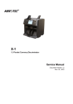
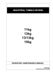
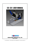
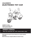
NC-6000 Compact Two Pockets Currency Discriminator Service Manual Document Version 1.0 Oct 1st, 2012 Masterwork Automodules Tech Corp Ltd. 11F-3, 3, Park St., Nangang, 11503, Taipei, Taiwan [email protected] COPYRIGHT © 2011 Masterwork Automodules Tech Corp Ltd. All rights reserved. This Document or any part thereof may no, without the prior written consent of Masterwork Automodules Tech Corp Ltd., be copied, reprinted or reproduced in any material form including, but without prejudice to the foregoing and not by way of exception photocopying, transcribing, transmitting or storing in any medium or translating into any language, in any form or by any means, including but not limited to, electronic, mechanical, xerographic, optical, magnetic, digital or other methodology. st Service Manual – NC-6000 Date: OCT 1 , 2012 (Version 1.0) CONTENT CHAPTER 1 INTRODUCTION ................................................................................................. 5 1.1 ABOUT NC-6000 SERVICE MANUAL ............................................................................................................. 5 1.2 IMPORTANT SAFETY PRECAUTION .................................................................................................................. 5 1.3 ABBREVIATIONS AND ACRONYMS .................................................................................................................. 5 1.4 CONTACT INFORMATION .............................................................................................................................. 6 CHAPTER 2 NC-6000 OUTLINE ............................................................................................. 7 2.1 NC-6000 AT A GLANCE ............................................................................................................................. 7 2.2 SPECIFICATION ........................................................................................................................................... 8 2.2.1 Functional and Mechanical Specification ...................................................................................... 8 2.2.2 Electrical Specification ................................................................................................................... 8 2.2.3 Interface Specification ................................................................................................................... 9 2.2.3.1 Thermal Printer (RS-232) ....................................................................................................... 9 2.2.3.2 Remote Display .................................................................................................................... 10 2.2.3.4 PC ........................................................................................................................................ 10 2.3 SYSTEM OVERVIEW .................................................................................................................................. 11 CHAPTER 3 MAINTENANCE ................................................................................................ 12 3.1 CLEANING THE COVER OF NC-6000 ............................................................................................................ 12 3.2 CLEANING THE BILL PATH OF NC-6000 ......................................................................................................... 12 CHAPTER 4 MAINTENANCE MODE .................................................................................... 13 4.1 TEST RUN – SIMPLE MODE ........................................................................................................................ 14 4.1.1 Run – Value List............................................................................................................................ 14 4.1.2 Run – Wavform ............................................................................................................................ 15 4.1.3 Test Solenoid & Brake .................................................................................................................. 15 4.2 TEST RUN – STRICT MODE ......................................................................................................................... 16 4.2.1 Run – Value List............................................................................................................................ 16 4.2.2 Run – Wavform ............................................................................................................................ 17 4.2.3 Test Solenoid & Brake .................................................................................................................. 17 4.3 UPGRADE MODE ..................................................................................................................................... 18 4.3.1 SD Upgrade .................................................................................................................................. 19 4.3.1.1 Show Ver ............................................................................................................................. 19 4.4 CALIBRATION MODE .................................................................................................................................. 20 4.4.1 Calibrate sensors.......................................................................................................................... 20 4.4.2 Adjust MG .................................................................................................................................... 22 4.4.3 Initialization ................................................................................................................................. 22 4.5 IR MODE ............................................................................................................................................... 23 Masterwork Automodules Tech. Corp., Ltd Confidential -2- Service Manual – NC-6000 st Date: OCT 1 , 2012 (Version 1.0) 4.5.1 IR Status ....................................................................................................................................... 23 4.5.3 Burn In ......................................................................................................................................... 24 4.5.4 Calibraiton of Hopper Sensor ...................................................................................................... 25 4.6 TEST DEVICE ........................................................................................................................................... 25 4.6.1 Solenoid ....................................................................................................................................... 25 4.6.2 Machine Running Status .............................................................................................................. 26 4.6.3 Test LCD ....................................................................................................................................... 27 4.6.4 Test Key ........................................................................................................................................ 27 4.6.11 Test Fan ...................................................................................................................................... 27 4.6.12 Test Sound ................................................................................................................................. 27 4.6.13 Test Encoder .............................................................................................................................. 28 Burn In .................................................................................................................................................. 28 4.6.15 Test SD ....................................................................................................................................... 28 Turn to the back side of the device and insert the SD card. ................................................................. 28 4.7 MACHINERY INFO..................................................................................................................................... 29 4.8 SETUP DEVICE PARAMETERS ....................................................................................................................... 29 4.8.1 Capacity of pockets ...................................................................................................................... 30 4.8.2 Speed mode ................................................................................................................................. 30 4.8.3 Detection Level ............................................................................................................................ 31 4.8.4 Count Mode Intensity .................................................................................................................. 31 4.8.5 Printer Type ................................................................................................................................. 31 4.8.6 Hpr Trigger Detection Mode ........................................................................................................ 31 CHAPTER 5 NC-6000 PART LIST AND DISASSEMBLY ........................................................... 32 5.1 TOOL PREPARATION .............................................................................................................................. 32 5.2 HOUSING ............................................................................................................................................... 33 5.2.1 Side Panel Left and Right ............................................................................................................. 35 5.2.2 Top Cover-ONE and TWO ............................................................................................................. 36 5.2.3 Lid Back-Frame ............................................................................................................................ 37 5.2.4 Back cover .................................................................................................................................... 37 5.3 TOTAL ASSEMBLY ..................................................................................................................................... 39 5.3.1 Upper Bill Path Module ............................................................................................................... 40 5.3.1.1 Upper Bill Path Plate .................................................................................................... 47 5.3.1.2 PCB NC6100-S board .................................................................................................... 48 5.3.1.3 PCB NC6100-IRTE Board ............................................................................................... 48 5.3.1.4 PCB NC6000-M134 Board ............................................................................................ 49 5.3.1.5 Retarding Wheel Module ............................................................................................. 49 5.3.2 Control Panel Module ............................................................................................................ 52 5.3.2.1 PCB NC6000-UI Board .................................................................................................. 55 Masterwork Automodules Tech. Corp., Ltd Confidential -3- Service Manual – NC-6000 st Date: OCT 1 , 2012 (Version 1.0) 5.3.2.2 Keypads ........................................................................................................................ 56 5.3.2.3 LCD Display ................................................................................................................... 57 5.3.2.4 PCB NC6000-UI_IRR Board ........................................................................................... 57 5.3.3 Stacker Module ...................................................................................................................... 58 5.3.3.1 Stacker and Reject Pocket ................................................................................................... 61 5.3.3.2 5.3.4 Reject Pocket Stoppers ................................................................................................. 61 Bottom Conveyor Module ..................................................................................................... 62 5.3.4.1 Bottom Conveyor Plate ................................................................................................ 64 5.3.4.2 PCB NC6000-DTE Board ................................................................................................ 65 5.3.5 Base Module .......................................................................................................................... 66 5.3.5.1 Timing Belts .................................................................................................................. 72 5.3.5.2 Reject Pocket Note Holder ........................................................................................... 72 5.3.5.3 Note Toggler ................................................................................................................. 73 5.3.5.4 Kicker Roller Module .................................................................................................... 74 5.3.5.5 PCB NC6000-DTE Board ................................................................................................ 75 5.3.5.6 PCB NC6000-IRTR2 board and IR Guide Box ................................................................ 77 5.3.5.7 Singler Module ............................................................................................................. 77 5.3.5.8 PCB NC6000-DTR Board ............................................................................................... 77 5.3.5.9 PCB NC6000-A Board.................................................................................................... 78 5.3.5.10 PCB NC6000-MOTOR Board ......................................................................................... 79 5.3.5.11 Power Tray .................................................................................................................... 80 5.3.5.12 Motor A and B .............................................................................................................. 80 5.3.5.13 Impeller ........................................................................................................................ 81 CHAPTER 6 TROUBLE SHOOTING ....................................................................................... 83 6.1 DEFINITION OF MESSAGE CODES ................................................................................................................. 83 6.1.1 Check Bill Path ............................................................................................................................. 83 6.1.2 Open Bill Path .............................................................................................................................. 83 6.1.3 Remove Banknotes ...................................................................................................................... 83 6.1.4 Error ............................................................................................................................................. 84 Masterwork Automodules Tech. Corp., Ltd Confidential -4- st Service Manual – NC-6000 Date: OCT 1 , 2012 (Version 1.0) Chapter 1 Introduction 1.1 About NC-6000 Service Manual This manual is for the maintenance of NC6000 and it includes the disassembly process, spare part replacement, basic inspection and repair. 1.2 Important Safety Precaution • NC-6000 is exclusively for indoor usages only, please do not use or install it outdoor. • Please check the adaptor and power cord periodically to protect from any damages. The power source is between AC 100 - 240V, 50/60 Hz. • Keep NC-6000 away from magnets, activated cellular phones, electrical appliances, or speakers within 13 cm/ 5 inches. • Please disconnect power adaptor and remove batteries when the machine left unused for a long time. • NC-6000 is designed for notes processing. Please process banknotes ought to be verified in the four orientations (“Head Up-Right”, “Head Reversed”, “Tail Up-Right” or “Tail Reversed”). 1.3 Abbreviations and Acronyms IR MA MB MG MR MT PC USB UV Infrared Masterwork Automodules Megabyte Magnetic Magnetoresistive Metal Thread Personal Computer Universal Serial Bus Ultraviolet Masterwork Automodules Tech. Corp., Ltd Confidential -5- st Service Manual – NC-6000 Date: OCT 1 , 2012 (Version 1.0) 1.4 Contact Information Masterwork Automodules Tech Corp Ltd. www.automodules.com Address: 11F-3, 3, Park St, Nangang, 11503, Taipei, Taiwan Tel: Fax: +886 2 2655 7997 +886 2 2655 7996 Email: [email protected] Masterwork Automodules Tech. Corp., Ltd Confidential -6- st Service Manual – NC-6000 Date: OCT 1 , 2012 (Version 1.0) Chapter 2 NC-6000 Outline 2.1 NC-6000 At A Glance Hopper Guide Top Bill Path Open Hopper 3.5 Inch color TFT LCD Display Control Panel Reject Pocket Stacker Pocket Bottom Bill Path Open PC Connection Socket Serial Port Power Switch Printer Power Socket Remote Display Socket SD Card Upgrade Socket Masterwork Automodules Tech. Corp., Ltd Confidential -7- st Service Manual – NC-6000 Date: OCT 1 , 2012 (Version 1.0) 2.2 Specification 2.2.1 Functional and Mechanical Specification Sensors: IR Array, MR, UV Denomination Detection: IR Transmission Dual User Operation: Yes Available Currencies USD, EUR, and up to 5 additional currencies Countable Note Size: 60 X 85 X 0.08mm ~ 100 X 190 X 0.12mm Hopper Capacity: 500 notes (circulated notes) Stacker Capacity: 200 notes (circulated notes) Reject Pocket Capacity: Max. 50 notes (circulated notes) Display: 3.5 Inch color TFT Display Language: English or Customized Feed System: Roller friction system Piece Count Speed: 1000/ 1200/ 1500 notes/min. (selectable) Denomination Count Speed: 1000 notes/min. Dimensions (mm): 272(W) x 272 (D) x 282 (H) Weight: Approx. 8.2 kg Operating Temperature Range: Humidity: Options: Remote Display / Thermal Printer 2.2.2 Electrical Specification Power Supply: 100 - 240V, 50/60Hz Power Consumption: Max. 50 W Masterwork Automodules Tech. Corp., Ltd Confidential -8- st Service Manual – NC-6000 Date: OCT 1 , 2012 (Version 1.0) 2.2.3 Interface Specification 2.2.3.1 Thermal Printer (RS-232) (A) Communication Conditions Item Specification Standard: EIA RS-232C Baud Rate: 9600bps ,38400bps ,115200bps Synchronous Method: Asynchronous Data Format: Start 1 bit Data 8 bits Parity None Stop 1 bit Connector: D-sub 9pin (male) Cable length: 15 m max (B) Interface Connector - Equipment Side Connector Pin NO. Signal Direction 1 ─── ─── 2 ─── ─── 3 TXD NC6000→thermal Printer 4 ─── ─── 5 GND ─── 4 ─── ─── 7 ─── ─── 8 ─── ─── 9 ─── ─── Masterwork Automodules Tech. Corp., Ltd Confidential -9- st Service Manual – NC-6000 Date: OCT 1 , 2012 (Version 1.0) 2.2.3.2 Remote Display (A) Communication Conditions Item Specification Standard: UART Baud Rate: 115200bps Synchronous Method: Asynchronous Data Format: Start 1 bit Data 8 bits Parity None Stop 1 bit Connector: Mini USB 5 pins (female) Cable length: 1.5m max (B) Interface Connector - Equipment Side Connector Pin NO. Signal Direction 1 VCC ─── 2 VCC ─── 3 RXD ─── 4 TXD NC6000→Remote display 5 GND ─── 2.2.3.4 PC Item Specification Data Communication Port USB Masterwork Automodules Tech. Corp., Ltd Confidential - 10 - Service Manual – NC-6000 st Date: OCT 1 , 2012 (Version 1.0) 2.3 System Overview Masterwork Automodules Tech. Corp., Ltd Confidential - 11 - st Service Manual – NC-6000 Date: OCT 1 , 2012 (Version 1.0) Chapter 3 Maintenance 3.1 Cleaning the Cover of NC-6000 Prepare a mixture of a gentle kitchen-use detergent (one that does not contain abrasive powder or strong chemicals such as acid or alkaline.) Use 5 parts water to 1 part detergent. Absorb the diluted detergent into a sponge. Squeeze excess liquid from the sponge. Wipe the cover with the sponge, use a circular motion and take care not to let any excess liquid drips into the interior of the device. Wipe the surface to remove the detergent. Rinse the sponge with clean running water. Wipe the over with the clean sponge. Wipe the surface again with a dry, soft lint-free cloth. Wait for the surface to dry completely and remove any fibers. 3.2 Cleaning the bill path of NC-6000 Open the bill path. Gently wipe it or dust the bill path with a MA brush or a dry, soft lint-free cloth. If stains remain, moisten a soft, lint-free cloth with water or a 50-50 mixture of isopropyl alcohol and water that does not contain impurities. Wring out as much of the liquid as you can. Wipe the bill path and the sensor surface again; do not let any liquid drip into the device. Repeat 1-5 to clean the conveyer path. *NOTE: Avoid spraying cleaner directly on the device, and be sure to day the bill path before closing it. Masterwork Automodules Tech. Corp., Ltd Confidential - 12 - st Service Manual – NC-6000 Date: OCT 1 , 2012 (Version 1.0) Chapter 4 Maintenance Mode Maintenance Mode is for testing and maintaining NC-6000 only. Please follow the instruction as below when operating under the mode, or there is a risk to damage the device. How to enter Maintenance mode: 1. Turn on the device. 2. Press and hold the “ ” and “ ” keys together on the initializing page. The 3. device enters the Maintenance mode automatically. After enter the test mode, use the following keys to 4. operate: F1 F1: Move Up. F2: Move Down. F2 : Toggle between options and/or confirm a selection. F3 : Go back to upper layer/Stop. Masterwork Automodules Tech. Corp., Ltd Confidential - 13 - st Service Manual – NC-6000 Date: OCT 1 , 2012 (Version 1.0) 4.1 Test Run – Simple Mode To test the feeding process with the four sets of IR trigger sensors in the bill path. 4.1.1 Run – Value List To check the gap adjustment by using the retrieved values. 1. Choose a desired speed for testing. 2. Change the solenoid to “Down” position. 3. Start “Run – Value List” by pressing the “ selecting on the item. ” after 4. Place notes a bundle of 50 pcs test (Denomination: 1USD) on the hopper and pull the hopper guide to fix the size of test note. The machine starts running once it detects notes on the hopper. Note: The distance of two sides from hopper to banknote shall be around 3mm to 5 mm. 5. Once notes proceed, sensors retrieve value and they are showed on the list. • MAX: Value of Tilt shall not over 4. • AVE: Value of Tilt shall not over 2. • QTY: Value of L shall not less than 10. • Value of IN Cnt and OUT Cnt shall be 50. *Note: Repeat the same process FIVE times and the result should be similar. If two or more test results are not under acceptable range, please adjust the gap and test. Masterwork Automodules Tech. Corp., Ltd Confidential - 14 - st Service Manual – NC-6000 Date: OCT 1 , 2012 (Version 1.0) 4.1.2 Run – Wavform To check the gap adjustment by using the graphic wave formed by the retrieved value. 1. Enter “Run – Wavform” by press the “ selecting on the item. 2. Place a bundle of 50 pcs test ” after notes (Denomination: 1USD) on the hopper and pull the hopper guide to fix the size of test note. The machine starts running once it detects notes on the hopper. Note: The distance of two sides from hopper to banknote shall be around 3mm to 5 mm. 3. The wave shall be drowned around the white line *Note: The information on Wave Form is for reference only, please base on the information from VALUE LIST to test and to adjust gap. 4. Press the “Move down” key to switch to next page and see the wave form of distance. *Note: The information on Wave Form is for reference only, please base on the information from VALUE LIST to test and to adjust gap. 4.1.3 Test Solenoid & Brake To test the functionality of solenoid and brake (Manually start). Place a bundle of 50 pcs (Denomination: 1USD) test notes on the hopper and pull the hopper guide to fix the size of test note. The machine starts running once it detects notes on the hopper. Note: The distance of two sides from hopper to the edge of banknote shall be around 3mm to 5 mm. Press the “ function. ” to activate the solenoid & Brake Masterwork Automodules Tech. Corp., Ltd Confidential - 15 - st Service Manual – NC-6000 Date: OCT 1 , 2012 (Version 1.0) The machine counts and the solenoid toggles between reject pocket and stacker. Check the two pockets to make sure that banknote are separated equally in both pockets. *Note: If the Solenoid &Break doesn’t function well, please contact MA. 4.2 Test Run – Strict Mode To test the feeding process with 128 pairs IR array and the four sets of IR trigger sensors in the bill path. 4.2.1 Run – Value List To check the gap adjustment by using the retrieved values. 1. Choose a desired speed for testing. 2. Change the solenoid to “Down” position. 3. Start “Run – Value List” by pressing the “ selecting on the item. ” after 4. Place notes a bundle of 50 pcs test (Denomination: 1USD) on the hopper and pull the hopper guide to fix the size of test note. The machine starts running once it detects notes on the hopper. Note: The distance of two sides from hopper to the edge of banknote shall be around 3mm to 5 mm. Masterwork Automodules Tech. Corp., Ltd Confidential - 16 - st Service Manual – NC-6000 Date: OCT 1 , 2012 (Version 1.0) 5. Once notes proceed, sensors retrieve value and they are showed on the list. • MAX: Value of Tilt shall not over 4. • AVE: Value of Tilt shall not over 2. • QTY: Value of L shall not less than 10. • Value of IN Cnt and OUT Cnt shall be 50. *Note: Repeat the same process FIVE times and the result should be similar. If two or more test results are not under acceptable range, please adjust the gap and test. 4.2.2 Run – Wavform To check the gap adjustment by using the graphic wave formed by the retrieved value. 1. Enter “Run – Wavform” by press the “ selecting on the item. 2. Place a bundle of 50 pcs test ” after notes (Denomination: 1USD) on the hopper and pull the hopper guide to fix the size of test note. The machine starts running once it detects notes on the hopper. 3. The wave shall be drowned around the white line *Note: The information on Wave Form is for reference only, please base on the information from VALUE LIST to test and to adjust gap. 4. Press the “Down” key to switch to next page and see the wave form of distance. *Note: The information on Wave Form is for reference only, please base on the information from VALUE LIST to test and to adjust gap. 4.2.3 Test Solenoid & Brake To test the functionality of solenoid and brake by using 128 pairs IR array (Manually start) Masterwork Automodules Tech. Corp., Ltd Confidential - 17 - st Service Manual – NC-6000 Date: OCT 1 , 2012 (Version 1.0) 1. Place a bundle of 50 pcs test notes (Denomination: 1USD) on the hopper and pull the hopper guide to fix the size of test note. The machine starts running once it detects notes on the hopper. Note: The distance of two sides from hopper to the edge of banknote shall be around 3mm to 5 mm. 2. Press the “ function. ” to activate the solenoid & Brake The machine counts and the solenoid toggles between reject pocket and stacker. Check the two pockets to make sure that banknote are separated equally in both pockets. *Note: If the Solenoid & Break doesn’t function well, please contact MA. 4.3 Upgrade Mode Using supported devices to upgrade NC-6000. 1. Insert SD card with upgrade firmware into the device. 2. Highlight the “SD” and press “ ” to enter the upgrade mode. 3. Once SD card is detected, a green mark shows next to the “Show Ver” option. Masterwork Automodules Tech. Corp., Ltd Confidential - 18 - st Service Manual – NC-6000 Date: OCT 1 , 2012 (Version 1.0) 4.3.1 SD Upgrade Before upgrade the SD card. 1. Get a folder with upgrading firmware and database from MA. 2. Put the folder into SD card with the folder name “_SD_Upgrade”. *Note: (1) File system must be FAT32, other type is not supported. (2) File name must be “_SD_Upgrade”. To upgrade the device with a SD card. 1. Once a SD card is detected, a green mark is shown next to “Show Ver” and the device is available to be upgraded via SD card. If not, a red cross is shown instead. 2. Highlight the desired option and press “ upgrade. ” to 3. A mark shall be shown next to the upgraded module. The following are the definitions of the status. : On the process of upgrading module. : The module has been upgraded correctly. : Upgrading process is failed. 4.3.1.1 Show Ver To check the available and currency firmware version. 1. The current module version and the available version on the SD card can be checked here. 2. The following are the definition of different signs. : A new version is found. : Firmware data cannot be found. : The same firmware as current version has been detected. : The available version is older than current firmware is detected. Masterwork Automodules Tech. Corp., Ltd Confidential - 19 - st Service Manual – NC-6000 Date: OCT 1 , 2012 (Version 1.0) 4.4 Calibration mode Before calibrating sensors. 1. Highlight the option and press “ ” 2. Use “F1” and “F2” key to adjust the dimension value of calibration paper. Note: Dimension value is stated on each calibraiton paper. 4.4.1 Calibrate sensors To calibrate the IR image. This function does not exist in NC6000. Step A: Transmission Calibration. side with foam downwards 1. Open the lid and insert the Calibration tool A (1.0mm for IR), side with foam downwards. Step A: 1.0mm for IR Dot on Cal. Tool. 2. Insert the dots on calibration tool to the holes on side plates. Hole on side plate 3. Adjust the position of the Cal tool to the center part of the bill path. Make sure the tool is placed at center. Masterwork Automodules Tech. Corp., Ltd Confidential - 20 - st Service Manual – NC-6000 Date: OCT 1 , 2012 (Version 1.0) 4. Close the Lid, check if the Cal tool is placed properly, no bending. Cal tool is not bowed 5. Move cursor to “2.Ver2-[a] Dark Paper” and double press “ ”. After the screen shows a black arrow beside the dimension value, wait for about 5 seconds. 6. Once a green mark appears on the screen, first calibration is completed. Step B: Transmission Calibration side with foam downwards 1. Open lid and remove calibration tool A (1.0mm For IR). 2. Insert the Calibration tool B (1.2mm for IR), side with foam downwards. Step B: 1.2mm for IR 3. Adjust the position of the Calibration tool to the center part of the bill path. Make sure the tool is placed at center. Masterwork Automodules Tech. Corp., Ltd Confidential - 21 - st Service Manual – NC-6000 Date: OCT 1 , 2012 (Version 1.0) 4. Close the Lid, check if the Cal tool is placed properly, no bending. Cal tool is not bowed 5. Move cursor to “3. Ver2-[b] Bright Paper” and double press “ ”. After the screen shows a black arrow beside the dimension value, wait for about 5 seconds. 6. Once a green mark appears, second calibration is completed. 7. Open lid and remove calibration tool B (1.2mm for IR). 8. Move to “Exit” and press “ layer. ” to go back to upper 4.4.2 Adjust MG To adjust the retrieved value of magnetic sensor. 1. Highlight the option and press “ ”. 2. Adjust the value of magnetic sensor by pressing the keys “F1” and “F2”. (from 000 to 128) Note: To adjust the MG value, please contact MA. 4.4.3 Initialization Initializing the sensor. Masterwork Automodules Tech. Corp., Ltd Confidential - 22 - st Service Manual – NC-6000 Date: OCT 1 , 2012 (Version 1.0) *Note: Initialization shall only be executed with indication from MA. 1. Press the “ ” key for the initialization and the display shows “Wait…”. Do not touch any button and wait until the process is finished. 2. Once the initialization process is done, the display shows “Init OK”. 3. Calibrate the device immediately. 4.5 IR Mode To check the status of IR sensors and triggers. 4.5.1 IR Status To see the IR triggers’ reactions. 1. In normal status, only the channel P2-Sol shows reaction curve. Masterwork Automodules Tech. Corp., Ltd Confidential - 23 - st Service Manual – NC-6000 Date: OCT 1 , 2012 (Version 1.0) 2. Once a IR sensor is covered, the curve on the display reacts. Users may use hand or supporting items to cover sensors and test the status of IR sensors. 3. The following are the actions to get reaction from IR sensors. HPR: Cover the trigger. P3-UpF: Reject pocket is full S0-SpP: Check notes in reject pocket. S1-SpD: Stacker is full. IR0-IR2, IRs: Sensors in top bill path. When top bill path is opened, there are reactions on the 4 channels. IR4-IR5: Open the cover lid, there are reactions on the 2 channels. IRR: Cover the trigger sensor of jam in reject pocket. (Refer to the pictures on the left side) 4.5.3 Burn In To burn in the 128 set IR array. [Factory used only]. 1. Highlight the option and press “ ” to enter the burn in mode. 2. Press “ ” to burn in IR array which will can keep the sensor in a stable situation. 3. Use “F1” and “F2” key to set the burn in time, and press “ ” to activate. IR array lights up while burn in is under processing. 4. Check the rollers and ensure each cog gears smoothly. 5. Press “ press “ ” to stop the burn in function and ” again to go back to the upper layer. Masterwork Automodules Tech. Corp., Ltd Confidential - 24 - st Service Manual – NC-6000 Date: OCT 1 , 2012 (Version 1.0) 4.5.4 Calibraiton of Hopper Sensor To calibrate the IR hopper sensor. 1. Highlight the option and press “ burn in mode. 2. Press “ ” to enter the ” to calibrate the hopper sensor. 3. Once a green mark appears beside the option, the calibration is completed successfully. 4. Highlight the option “Exit” and press “ to the upper layer. ” to go back Note: In order to calibrate hopper sensor, the status of Hpr Ttrigger Detection Mode(Under the opiton Setup DeviceParameters) shall be in Ver2. To setup the Hpr Detection Mode, refer to page 32. 4.6 Test Device To test the functionalities of all the parts and to make sure the stability of machine. 4.6.1 Solenoid To test the reaction time of solenoid. 1. Highlight the option and press “ ” key. 2. Solenoid toggles between UP and DOWN to stacker pocket and the display shows a speed. Masterwork Automodules Tech. Corp., Ltd Confidential - 25 - st Service Manual – NC-6000 Date: OCT 1 , 2012 (Version 1.0) 4.6.2 Machine Running Status Testing the machine for basic running status under different speeds. Sub singler 1. Set a preferred speed for testing the device. 2. Different speed can be set by press “ ” key: 600, 650, 700, 750, 800, 1000, 1200, Min and Max. *Raise the “sub singler roller” to segregate the sound of vibration when the motor is running. 3. Highlight the option and press “ ” key. 4. Check if the rollers run well to test the functionality of front motor. 5. Highlight the option and press “ ” key. 6. Highlight the option “Motor Run” and press “ key. 7. Motor starts running. ” *Note: The option “Motor Run” changes to “Motor Stop”. 8. Once confirming all works well, Highlight the option “Motor Stop” and press “ 9. ” key. A number of Encoder is showed on the right side of the “Motor Run” 10. Switch motor speed and repeat the test process with each speed. (600→650→700→800→1000→1200→Min→Max→6 00) *If the motors run with strange noise during the test, please contact MA. Masterwork Automodules Tech. Corp., Ltd Confidential - 26 - st Service Manual – NC-6000 Date: OCT 1 , 2012 (Version 1.0) 4.6.3 Test LCD Testing the functionality of LCD display. 1. Highlight the option and press “ ” key. 2. The display shows RED, GREEN and BLUE continually, then it goes back to the test mode. 4.6.4 Test Key Testing the functionality of each key. 1. Press a key, the key number shows on the top left side of the screen. 2. When pressing different key, a reaction number shows on the display. 4.6.11 Test Fan Testing the functionality of fan. 1. Highlight the option and press “ ” key. 2. The fan starts running. Put a hand on the back side of the device to feel if the fan works properly. 3. Press “ ” key again to stop it. 4.6.12 Test Sound Testing the functionality of sound. 1. Highlight the option and press “ sound can be heard. Masterwork Automodules Tech. Corp., Ltd Confidential - 27 - ” key. A testing st Service Manual – NC-6000 Date: OCT 1 , 2012 (Version 1.0) 4.6.13 Test Encoder Testing the functionality of encoder. 1. Highlight the option and press “ ” key. The motor starts running a certain time. 2. A number of Encoder is shown on the left side of the option. The shown number of encoder during every test should be similar. Burn In To burn in the entire device. [Factory used only]. 1. Highlight the option and press “ the burn in mode. ” to enter 2. Press “ ” to burn in the entire device (Motors, rollers.etc) which will can keep the functionalities of machine in a stable situation. 3. Use “F1” and “F2” key to set the burn in time, and press “ ” to activate. Motors and rollers keep running while burn in is under processing. 4. Press “ ” to stop the burn in function and press “ layer. ” again to go back to the upper 4.6.15 Test SD Test the functionality of SD interface. Turn to the back side of the device and insert the SD card. 1. Highlight the “Test SD” option and press “ ”. The following are the definitions of different numbers. Masterwork Automodules Tech. Corp., Ltd Confidential - 28 - st Service Manual – NC-6000 Date: OCT 1 , 2012 (Version 1.0) 0: SD card is not inserted. 1: SD card is detected. 2: SD card is not detected well. * In case of 2, Please check if the SD card is completely inserted. 4.7 Machinery Info To look over the date of production, serial number and firmware version on the machine. 1. Use the “F1” and “F2” key to highlight “Machinery Info” under the main menu, and press “ 2. ” for confirming selection. All the versions information of firmware and detection is showed on the display. *Note: If currency list isn’t shown completely on the display, please press “Down” key to move to next page. 3. Press “F2” to see the completed currency version. 4. Press “ ” to go back to upper layer. 4.8 Setup Device Parameters To change the machine setting parameters. 1. Use the “F1” and “F2” key to highlight the option and press the “ between options. 2. ” to toggle After modifying the setting, highlight SAVE and press “ ” to confirm setting. Once the display shows “SAVE OK”, the modification is saved. 3. To go back to factory default setting, highlight the initialization and press “ Masterwork Automodules Tech. Corp., Ltd Confidential - 29 - ”. st Service Manual – NC-6000 Date: OCT 1 , 2012 (Version 1.0) *Note: It’s suggested to use default setting on the device. 4.8.1 Capacity of pockets To change the default capacity of pockets. 1. To change the maximum capacity of banknote for reject pocket. Options: 5, 10, 15, 20, 25, 30 2. To change the maximum capacity of banknote for stacker. Options: 50, 100, 150, 200, 250, 300, 350, 400 *Factory Deault Setting: -Pocket Up (reject pocket): 30 -Pocket Down (stakcer): 250. 4.8.2 Speed mode To change the setting of speed. 1. Highlight the desired speed mode and press “ change the low, normal and high mode speed settings. Options: 600, 650, 700, 750, 800, 1000, 1200. 2. Press “Save” to keep the change of setting and press “Exit” to go back to the upper layer. *Factory Deault Setting for Detection and SN mode: - low 600, normal 800, high 1000. *Factory Deault Setting for Count mode: - low 600, normal 1000, high 1200. Masterwork Automodules Tech. Corp., Ltd Confidential - 30 - ” to st Service Manual – NC-6000 Date: OCT 1 , 2012 (Version 1.0) 4.8.3 Detection Level 1. Highlight the “Count Mode-Light intensity” and change the level of intensity 0(low) to 3(high) in count mode by pressing “ ”. Note: It’s suggested to use default setting on the device. Value of initialization should be 0. 4.8.4 Count Mode Intensity This function does not exist in NC6000. 4.8.5 Printer Type Set up the printer type 1. Highlight the “Printer Type” and change the printer type by pressing “ ”. 2. There are two printer type option can be set. Use “F1” and “F2” keys to select the desired printer type and press “ switch the setting. *Printer types: -Thermal Printer -Dot-Matrix Printer ” to Note: Be aware which type of printer is connected to the device before changing the setting. 4.8.6 Hpr Trigger Detection Mode Set up the Detection Mode to enable the Calibration Hpr function in IR Mode 1. Highlight the option and change the detection mode version by pressing “ ”. Note: Calibration Hpr function can only be operated in Hpr Trigger Detection Mode V2. Masterwork Automodules Tech. Corp., Ltd Confidential - 31 - st Service Manual – NC-6000 Date: OCT 1 , 2012 (Version 1.0) Chapter 5 NC-6000 part list and Disassembly 5.1 Tool preparation Screwdriver (+) Screwdriver (-) Long Nose Plier 7 mm Wrench 3 mm Hex Key 1.5 mm Hex Key Masterwork Automodules Tech. Corp., Ltd Confidential - 32 - st Service Manual – NC-6000 Date: OCT 1 , 2012 (Version 1.0) 5.2 Housing No Part Name Accessory Code Picture Q’ty 1 Top cover-ONE 3PP02100130041 1 Paper-Guide (Holder) 3PP52500100170 1 1 Paper-Guide-L 3GE40008171010 Paper-Guide-R 3GE40008171020 Gear-14T 3GE00814261100 1 1 1 Rack BK 3NC90800120010 1 Top cover-TWO 3PP02100130021 Masterwork Automodules Tech. Corp., Ltd Confidential - 33 - st Service Manual – NC-6000 Date: OCT 1 , 2012 (Version 1.0) 2 1 Banknote guide- L 3PP92110100010 1 Banknote guide- R 3PP92110100020 3 1 Side Panel L 3PP32100040060 4 1 Side Panel R 3PP42100040060 Back Cover 3PP12100040010 Lid Back-Frame 3PP22100130010 1 5 6 Masterwork Automodules Tech. Corp., Ltd Confidential - 34 - 1 st Service Manual – NC-6000 Date: OCT 1 , 2012 (Version 1.0) 5.2.1 Side Panel Left and Right Left 1. Prepare the machine and all the necessary tools. Right 2. Turn the machine to rear side and loosen the two screws (M3x5-Countersunk) on right hand. 3. Turn the machine to the front side and loosen the screw (Ø3×8-round head) on the stacker. 4. Open the upper bill path and loosen the screw (Ø3×8-countersunk) on the right side. Masterwork Automodules Tech. Corp., Ltd Confidential - 35 - st Service Manual – NC-6000 Date: OCT 1 , 2012 (Version 1.0) 5. Disassemble the Side Panel-R from the machine. *Note: When assembling the side cover, please make sure the plastic cover and metal plate fitted to each other. 6. Repeat the steps 1 to 5 to dismount the Side Panel-L. *Note: Please notice the same as above when assebling the side panel-L. 5.2.2 Top Cover-ONE and TWO 1. Loosen the two screws (M3x5-Countersunk) on the right side of top cover. 2. Loosen the two screws (M3x5-Countersunk) on the left side of top cover. 3. Disassemble top cover ONE and TWO from the machine. Masterwork Automodules Tech. Corp., Ltd Confidential - 36 - st Service Manual – NC-6000 Date: OCT 1 , 2012 (Version 1.0) 5.2.3 Lid Back-Frame 1. Loosen the two screws (M3x5-Countersunk) on the Lid Back-Frame of right sides. 2. Loosen the another two screws (M3x5-Countersunk) on the left side. *Note: When assembling the Lid Back-Frame, please organize the cable of motor baord to prevent damage on the cable. 3. Disassemble Lid Back-Frame from the machine. 5.2.4 Back cover 1. Loosen the screws (M3x5-Countersunk) on the both sides of back cover. Masterwork Automodules Tech. Corp., Ltd Confidential - 37 - Service Manual – NC-6000 st Date: OCT 1 , 2012 (Version 1.0) 2. Disassemble back cover from the machine. Masterwork Automodules Tech. Corp., Ltd Confidential - 38 - Service Manual – NC-6000 st Date: OCT 1 , 2012 (Version 1.0) 5.3 Total Assembly Masterwork Automodules Tech. Corp., Ltd Confidential - 39 - st Service Manual – NC-6000 Date: OCT 1 , 2012 (Version 1.0) 5.3.1 Upper Bill Path Module No. Part Number Part Name in English 3TP00012030011 feed shaft (12) 1 3NC51500120010 feed BK frame 1 3SC00040100200 1 M4x10-Round head (w/ spring washer) Picture Unit 5 3SP01150070010 Torsion (1.5-Ø14) 1 3TP20000030010 feed adjustment bar 1 3SC86030061000 M3x6 hex socket set screw (Nyloc) 1 Masterwork Automodules Tech. Corp., Ltd Confidential - 40 - st Service Manual – NC-6000 3NC00800120020 Top Frame 1 3TP20000030020 feed adjustment fixed 1 3SC00030100200 2 Date: OCT 1 , 2012 (Version 1.0) M3x10-Round head (w/ spring washer) 2 3SP31140210010 Compression adjustment (1.4-21) 1 3TP20000030030 SCREW M8 (P0.5) 1 3TP10816060010 shaft sleeve (8-16) 2 WA061208KN7000 E-ring (Ø6) 2 3TP10608030010 shaft tube (8) 2 WA040906KN7000 E-ring (Ø4) 2 3OC05290000300 Square Snap Bushing 1 3SC70040101000 M4x10 hex socket set screw 2 3NU0040030200 M4 bolt 4 3TP00008030031 Retarding wheel shaft 1 Masterwork Automodules Tech. Corp., Ltd Confidential - 41 - st Service Manual – NC-6000 Date: OCT 1 , 2012 (Version 1.0) 3RPA3100220010 Retarding wheel 2 3SC86030061000 M3x6 hex socket set screw (Nyloc) 5 3PP52600100180 Feed idler wheel arm holder 1 3TP00005030030 metal idler wheel 1 3TP19916010000 single direction bearing holder 1 BEHF0612R01010 Single Direction Bearing 1 3WA60500217000 E-ring (Ø5) 1 BE0688ZZ160511 flange bearing (688ZZ) 1 3TP10817060010 feed shaft (8) singler spacer 1 3PP52600100191 Feed idler wheel holder 1 3TP00005030020 idler wheel shaft (5) 1 3RPA3120220050 idler wheel(11-5-19) 1 3SP01080040010 Torsion idler-L (0.8-Ø5.5) 1 3SP01080040020 Torsion idler-R (0.8-Ø5.5) 1 3 Masterwork Automodules Tech. Corp., Ltd Confidential - 42 - st Service Manual – NC-6000 SC30006M05NW00 Date: OCT 1 , 2012 (Version 1.0) M3x6-Round head (w/ spring washer) 1 S-BNC6000A06 NC6000-M134 1 3SC52030050200 Ø3×5-Pan 4 3PP02500100051 Upper Bill Path Plate 1 3PP82400000140 LED LENS (Top assem) 4 3RPA3120220060 idler wheel(5-6-22) 2 3TP00006030021 idler wheel shaft (6) 2 3SP01060020010 Torsion idler (0.6-Ø3.0) 2 3PP52100110120 LED LENS holder 1 3PP82100000030 LED LENS 1 7 S-BNC6000A05 NC6000-IRTE 1 8 S-BNC6000A07 NC6000-S 1 4 5 6 Masterwork Automodules Tech. Corp., Ltd Confidential - 43 - st Service Manual – NC-6000 3SC02030080200 Date: OCT 1 , 2012 (Version 1.0) Ø3×8-Round head Masterwork Automodules Tech. Corp., Ltd Confidential - 44 - 7 st Service Manual – NC-6000 Date: OCT 1 , 2012 (Version 1.0) 1. Turn the machine to left side and find the two encoders. 2. Loosen the two screws (M4x6-round head with spring washer) on the encoder. *Note1: Take off the encoder before proceeding disassembly of the machine in order to prevent damaging them. *Note2: After assembling the encoders, make sure they are fixed correctly on the machine or it will cause strange sounds during operation. Hold the sides of encoder film and check if the film are fixed and not possible to move. 3. Loosen the screw (M3x6-Rround Head with spring washer)on the both sides of EMI plate and disassemble it from the machine. Masterwork Automodules Tech. Corp., Ltd Confidential - 45 - st Service Manual – NC-6000 Date: OCT 1 , 2012 (Version 1.0) 4. Turn the machine to the left side and release the cable from the cable clamp. 5. Disconnect the two cables which are connected to the PCB-Motor board. 6. Turn the machine to the rear side and take off the two plastic e-ring (Ø6) from the shaft of top assembly. 7. Dismount the upper bill path module from the machine. a. a. Remove the shaft from the Position (Feed)-L and R. b. Take off the plastic e-ring (Ø6) from the shaft. c. Disassemble the top assembly shaft from the machine. d. d. Release the cable from the Square Snap Bushing b. and c. 8. The upper bill path module is free to be removed from the machine. Masterwork Automodules Tech. Corp., Ltd Confidential - 46 - st Service Manual – NC-6000 5.3.1.1 Date: OCT 1 , 2012 (Version 1.0) Upper Bill Path Plate 1. Turn the upper bill path module and have the sensor side down. 2. Loosen the three screws (Ø3x8-Round Head) to release the ground cables. 3. Loosen the two screws (Ø3x8-Round Head) on the both sides. *Note: When assembling the upper bill path plate with retarding wheel module, please make sure the space between the wheel module and the plastic. 4. The upper bill path plate is removed from the retarding wheel module. Masterwork Automodules Tech. Corp., Ltd Confidential - 47 - st Service Manual – NC-6000 5.3.1.2 Date: OCT 1 , 2012 (Version 1.0) PCB NC6100-S board 1. Release the cables from the connecters. *Note: When plugging in the cable on the connecters, please make sure all the pins are well connected on the cable. 2. Loosen the four screws (Ø3x8-Round Head) on the PCB-S board. 3. Pull up straightly the PCB-S board. 4. The PCB-S board is removed from the upper bill path module. 5.3.1.3 PCB NC6100-IRTE Board 1. Pull up the NC6100-IRTE board. Masterwork Automodules Tech. Corp., Ltd Confidential - 48 - st Service Manual – NC-6000 Date: OCT 1 , 2012 (Version 1.0) 2. The LED Len is under the NC6100-IRTE board. 5.3.1.4 PCB NC6000-M134 Board 1. Loosen the four screws (Ø3×5-Pan) on NC6000-M134 board. 2. The NC6000-M134 board is now free to be removed. 5.3.1.5 Retarding Wheel Module 1. Find the retarding wheel module. Masterwork Automodules Tech. Corp., Ltd Confidential - 49 - the st Service Manual – NC-6000 Date: OCT 1 , 2012 (Version 1.0) 2. Use a 3mm hex key to loosen the two hex flange (M4×10) 3. Use a 1.5mm hex key to release the screw on the retarding wheel spacer. *Note: When assembling the singler spacer, please use two pcs of milar film to maintein a certain distance between the spacer and the top frame. 4. Release the E-ring from the left side of shaft by using a screwdriver (-). Masterwork Automodules Tech. Corp., Ltd Confidential - 50 - st Service Manual – NC-6000 Date: OCT 1 , 2012 (Version 1.0) 5. Remove the bearing from the retarding wheel shaft. 6. The retarding wheel is now free to be removed from the module. Masterwork Automodules Tech. Corp., Ltd Confidential - 51 - st Service Manual – NC-6000 Date: OCT 1 , 2012 (Version 1.0) 5.3.2 Control Panel Module No. Part Number Part Name in English Picture Unit 3PP02100130030 Top front 1 3SC16030050200 M3x5-Countersunk 4 S-BNC6000A10 NC6000-IRR 1 3PP72100000061 hopper sensor holder 1 3SC02030080200 Ø3×8-Round head 1 1 2 Masterwork Automodules Tech. Corp., Ltd Confidential - 52 - st Service Manual – NC-6000 Date: OCT 1 , 2012 (Version 1.0) 3PP72000080150 Front panel 1 3SC02030080200 Ø3×8-Round head 2 4 C-L00010 TFT LCD Panel 1 5 3NC90800120050 LCD Holder 1 3PP62000080140 14 rubber button 1 3PP62000080170 5 rubber button 1 3RP13400100040 14 rubber button 3RP13400100050 5 rubber button S-BNC6000A02 NC6000-UI 1 3ST4NC6000G020 Metal Dome 14 key 1 3 6 7 8 Masterwork Automodules Tech. Corp., Ltd Confidential - 53 - st Service Manual – NC-6000 Date: OCT 1 , 2012 (Version 1.0) 3ST4NC6000G010 Metal Dome 5 key 1 3SC02030080200 Ø3×8-Round head 2 3SC52030050200 Ø3×5-Pan 4 Masterwork Automodules Tech. Corp., Ltd Confidential - 54 - st Service Manual – NC-6000 Date: OCT 1 , 2012 (Version 1.0) 1. Loosen the two screws (M3x5-Countersunk) on the control panel module. 2. Loosen the screws (M3x5-Countersunk) on the both sides of the hopper. 3. Release the ground cable by loosening the screw (M3x6-Rround Head with spring washer). 4. Disconnect the cables on the PCB board. 5. The control panel module is removed from the machine. 5.3.2.1 PCB NC6000-UI Board 1. Turn the control panel module to the rear side. 2. Release the tenon of control panel assembly from the control panel plate. Masterwork Automodules Tech. Corp., Ltd Confidential - 55 - st Service Manual – NC-6000 Date: OCT 1 , 2012 (Version 1.0) 3. The control panel assembly is now free to be removed. 4. Turn the control panel to the rear side. 5. Loosen the four screws (Ø3x5-Pan) on the NC6100-UI board. 6. Loosen the screw (Ø3x8-Round Head) on the NC6100-UI board. 7. Release the FCC cable of LCD display from the connector. 8. The NC6100-UI board is now free to be removed. 5.3.2.2 Keypads 1. Pull out the keypads from the control panel. Masterwork Automodules Tech. Corp., Ltd Confidential - 56 - st Service Manual – NC-6000 Date: OCT 1 , 2012 (Version 1.0) 2. The left and right keypad is now removed. 5.3.2.3 LCD Display 1. Pull out the LCD display from the control panel. 2. The LCD display and LCD holder are removed from the control panel. 5.3.2.4 PCB NC6000-UI_IRR Board 1. Loosen the screw (Ø3x8-Round Head) on the NC6000 UI_IRR board. 2. The NC6000 UI_IRR board is now removed from the hopper set. Masterwork Automodules Tech. Corp., Ltd Confidential - 57 - st Service Manual – NC-6000 Date: OCT 1 , 2012 (Version 1.0) 5.3.3 Stacker Module No. 1 2 Part Number Part Name in English 3PP72100130130 Outlet part 2 1 3PP82400000080 Led (Outlet part 2) 1 3PP82100000020 reject sensor light guide 1 3SC52030050200 Ø3×5-Pan 1 3SC12030080200 Ø3×8-Countersunk 2 3PP92400020110 Reject stopper mirror 1 Masterwork Automodules Tech. Corp., Ltd Confidential - 58 - Picture Unit st Service Manual – NC-6000 3 4 Date: OCT 1 , 2012 (Version 1.0) 3PP92400020120 Reject stopper 1 3SP00050080010 Torsion reject (0.5-Ø2.7) 2 3TP00002030010 Reject shaft (2) 2 3PP72100130140 Outlet part 1 1 3OC25390000000 static brush 3 3NC90602190010 Static Brush Fixed BK 1 C01NN01NN130 Harness - ESD1 1 3SC12030080200 Ø3×8-Countersunk 2 3NC80300190020 Outlet Static BK 1 3PP92100040100 Sensor cover 1 3SC12030080200 Ø3×8-Countersunk 2 5 Masterwork Automodules Tech. Corp., Ltd Confidential - 59 - st Service Manual – NC-6000 Date: OCT 1 , 2012 (Version 1.0) 1. Lay down the machine and loosen the four screws (Ø3x8-Countersunk) on the bottom of the machine. 2. Release the stacker stopper and stacker static plate from the stacker module. 3. Pull out the stacker module straightly and slowly. *Note: There are few cables connected between the stacker module and the PCS boards. 4. The stacker module is now removed from the machine. Masterwork Automodules Tech. Corp., Ltd Confidential - 60 - st Service Manual – NC-6000 Date: OCT 1 , 2012 (Version 1.0) 5.3.3.1 Stacker and Reject Pocket 1. Loosen the two screws (Ø3x8-Countersunk) ob the both sides of the stacker module. 2. Release the reject pocket plate from the assembly. 3. The reject pocket is removed from the stacker module. 5.3.3.2 Reject Pocket Stoppers 1. Get the reject pocket plate which is disassembled from the stacker module. 2. Release the shaft from the reject pocket stopper with the indicated direction. Right Side 3. The stopper and the spring are now free to be removed. *Note: The right and left stopper are not the same, please notice the mark on the stopper as the picture below. Left Side R Masterwork Automodules Tech. Corp., Ltd Confidential - 61 - L st Service Manual – NC-6000 Date: OCT 1 , 2012 (Version 1.0) 5.3.4 Bottom Conveyor Module No. Part Number Part Name in English Picture Unit 1 3PP12100130020 Back Lid 1 3PP22500100031 Bottom Conveyor plate 1 3TP00007030010 idler wheel shaft-A (7) 2 3RPA3120220060 idler wheel(5-6-22) 4 3TP00006030030 idler wheel shaft-B (6) 1 2 Masterwork Automodules Tech. Corp., Ltd Confidential - 62 - st Service Manual – NC-6000 3 Date: OCT 1 , 2012 (Version 1.0) 3RPA3120220070 idler wheel(5-6-35) 3 3WA60500217000 E-ring (Ø5) 10 3SP02060030010 Torsion idler (0.6-Ø6.8) 6 3PPA2600100110 Idler Fixed 6 3SC02030080200 Ø3×8-Round head 6 3PP62100100150 Back lid connector 2 S-BNC6000A11 NC6000-DTE 1 3PP52400000130 Led pcb holder (2LED) 1 3SC52030050200 Ø3×5-Pan 1 3SC02030080200 Ø3×8-Round head 2 Masterwork Automodules Tech. Corp., Ltd Confidential - 63 - st Service Manual – NC-6000 Date: OCT 1 , 2012 (Version 1.0) 1. Open the back lid. 2. Release the back lid connector from the back lid. 3. Release the E-ring (Ø4) from the both side of shaft 4. The back lid is now removed. 5.3.4.1 Left Side Bottom Conveyor Plate 1. Loosen the screw (M4x6-Round Head) on the both side. Right Side Masterwork Automodules Tech. Corp., Ltd Confidential - 64 - st Service Manual – NC-6000 Date: OCT 1 , 2012 (Version 1.0) 2. Disconnect the indicated cable from the connector. 3. Pull out slowly the bottom conveyor plate. *Note: If it results dificulty when pulling out the bottom conveyor plate, please check if the cable has been released. The bottom conveyor plate has been removed from the machine. 5.3.4.2 PCB NC6000-DTE Board 1. Loosen the two screws (Ø3x8-Round Head) on the NC6000-DTE board. 2. The NC6000-DTE board is now removed from the machine. Masterwork Automodules Tech. Corp., Ltd Confidential - 65 - st Service Manual – NC-6000 Date: OCT 1 , 2012 (Version 1.0) 5.3.5 Base Module No. 1 Part Number Part Name in English OSPSOLRSA32470 Solenoid 1 3NC50800120121 Solenoid Cover 1 3PP62500100160 Note Toggler 1 Masterwork Automodules Tech. Corp., Ltd Confidential - 66 - Picture Unit st Service Manual – NC-6000 2 Date: OCT 1 , 2012 (Version 1.0) 3TP00306130010 Interrupter bar 1 3PPA2600100120 Shaft sleeve (interrupter) 1 3NC60800120030 Interrupter Plate 1 3SC36030060200 M3×6-Round washer 2 SC30006M05NW00 M3x6--Rround head (w/ spring washer) 1 3PP92600100130 Reject pocket note holder 1 S-BNC6000A13 NC6000-RJP 1 SC30006M05NW00 M3x6-Round head w/ spring washer 2 S-BNC6000A10 NC6000-IRR 1 3PP72100000061 hopper sensor holder 1 3SC00030100200 M3x10-Round head w/ spring washer (PH#2) 1 S-BNC6000A12 NC6000-DTR 1 3PP52400000130 Led pcb holder (2LED) 1 3 4 5 Masterwork Automodules Tech. Corp., Ltd Confidential - 67 - st Service Manual – NC-6000 Date: OCT 1 , 2012 (Version 1.0) 3SC52030050200 Ø3×5-Pan (PH#2) 1 3SC00030100200 M3x10-Round head w/ spring washer (PH#2) 2 3NCA0300190010 Encoder wheel 2 3SC00040060200 M4x6-Round head w/ spring washer 2 3TP00008030050 Kicker roller shaft 1 3OC27170000000 Aperture spring pin (Ø3x14) 2 3RPA3100220020 kicker wheel 2 WA061208KN7000 E-ring (Ø6) 2 3TP00010030010 Singler shaft (10) 1 3OC27170000000 Aperture spring pin (Ø3x14) 1 3RPA3100220030 Singler wheel 2 6 7 8 Masterwork Automodules Tech. Corp., Ltd Confidential - 68 - st Service Manual – NC-6000 9 Date: OCT 1 , 2012 (Version 1.0) 3RPA3100220040 Singler wheel - driver 1 3WA41050917000 Wave washer (Ø10.5) 1 3WA01040209000 Flat Washer (Ø10.4×Ø21×1.5t) 1 3PPA2600100130 Singler wheel fixer 1 S-BNC6000A11 NC6000-DTE 1 3PP52400000140 Led pcb holder (3LED) 1 3SC52030050200 Ø3×5-Pan (PH#2) 1 3SC00030100200 M3x10-Round head w/ spring washer 2 3PP52400000160 IR guide box 1 3PP82400000070 transmission emitter cover 1 S-BNC6000A04 NC6000-IRTR2 1 3SC52030050200 Ø3×5-Pan 2 10 Masterwork Automodules Tech. Corp., Ltd Confidential - 69 - st Service Manual – NC-6000 Date: OCT 1 , 2012 (Version 1.0) 3SC00030100200 M3x10-Round head (w/ spring washer) 4 3NC20800120060 Power BK 1 ED000003F002 AC socket EMI filter 1 C05MH03NN125 Harness - AC_IN 1 C-F00003 Fan 1 3SC12040120200 Ø4×12-Countersunk 4 3OC04290000100 Wire Holder A 1 S-BNC6000A08 NC6000-COM 1 SC30006M05NW00 M3x6-Round head w/ spring washer 2 M6 hex socket set screw 4 C-V00016 Power Supply - Open Frame 1 3SC16030100200 M3×10-Countersunk 4 3SC16030050200 M3x5-Countersunk 2 3LB0003M225000 Timing Belt (225-3Mx6mm) 1 11 12 Masterwork Automodules Tech. Corp., Ltd Confidential - 70 - Service Manual – NC-6000 st Date: OCT 1 , 2012 (Version 1.0) 13 3LB0S20M160000 Timing Belt (160-S2Mx6mm) 1 14 3LB0S30M189000 Timing Belt (189-S3Mx6mm) 1 Masterwork Automodules Tech. Corp., Ltd Confidential - 71 - st Service Manual – NC-6000 5.3.5.1 Date: OCT 1 , 2012 (Version 1.0) Timing Belts 1. Turing the gear (A) and pulling out the timing belt from the gear (B) to release the timing belt 160mm-S2M. B A 2. Use the same way as the first step to release the timing belt 189mm-S3M from the gears. B A 3. Repeat the disassembly way to release the timing belt 225mm-3M from the gears. *Note: When assembling the drive belt, please make sure A B the rollers are in correct positions. The rubber part of the 全部露出 roller shall align to the The rubber part aligns the hopper set. lower part of the hopper set. 5.3.5.2 Reject Pocket Note Holder 1. Push the reject pocket note holder from sides and release it from the tenon. Masterwork Automodules Tech. Corp., Ltd Confidential - 72 - st Service Manual – NC-6000 Date: OCT 1 , 2012 (Version 1.0) 2. The reject pocket holder is now removed from the machine. 5.3.5.3 Note Toggler 1. Left Side Loosen the screw (M3×6-Round Washer) on the solenoid interrupter plate and it’s free to be removed. 2. Loosen the screw (M3×6-Round Washer) on the note toggler. 3. 1) Loosen the screw (M3x6-Rround Head with spring washer) on the solenoid cover. 4. The solenoid cover is now free to be removed. Masterwork Automodules Tech. Corp., Ltd Confidential - 73 - st Service Manual – NC-6000 Right Side Date: OCT 1 , 2012 (Version 1.0) 5. Pull out the solenoid to remove it from the machine. 6. Release the plastic E-ring and the bearing from the shaft. 7. The note toggler is now free to be removed from the machine. 5.3.5.4 Left Side Kicker Roller Module 1. Release the plastic E-ring Ø6 from the shaft of kicker roller module. Right Side Masterwork Automodules Tech. Corp., Ltd Confidential - 74 - st Service Manual – NC-6000 Date: OCT 1 , 2012 (Version 1.0) 2. Release the bearing (688zz) from the shaft of kicker roller module. 3. 5.3.5.5 Left Side The kicker roller module is now free to be removed. PCB NC6000-DTE Board 1. Loosen the screw (M3x6-Rround Head with spring washer)on both sides. Right Side 2. Turn the bill path upward slowly. Masterwork Automodules Tech. Corp., Ltd Confidential - 75 - st Service Manual – NC-6000 Date: OCT 1 , 2012 (Version 1.0) 3. Release the cable from the connector. 4. The bill path is now removed from the machine. 5. Loosen the two screws (M3x10-Round Head with spring washer) on the NC6000-DTE board. 6. The NC6000-DTE board is now free to be removed from the bill path. Masterwork Automodules Tech. Corp., Ltd Confidential - 76 - st Service Manual – NC-6000 5.3.5.6 Date: OCT 1 , 2012 (Version 1.0) PCB NC6000-IRTR2 board and IR Guide Box 1. Loosen the four screws (M3x10-Round Head with spring washer) on the NC6000-IRTR2 board. 2. The NC6000-IRTE2 board is now free to be removed from the bill path. 5.3.5.7 Singler Module 1. Release the bearing (688zz) from the shaft of singler module. 2. 5.3.5.8 The singler module is now free to be removed. PCB NC6000-DTR Board 1. Loosen the two screws on the NC6000-DTR boards and remove the board from the bill path. Masterwork Automodules Tech. Corp., Ltd Confidential - 77 - st Service Manual – NC-6000 5.3.5.9 Date: OCT 1 , 2012 (Version 1.0) PCB NC6000-A Board Left Side 1. The NC6000-A board is on the left side of the machine. 2. Disconnect the cables from the NC6000-A board. COM USB *Note: The following are the positions of cables to the corresponded connecter. INTJ3 RJP J7 IRR J9 INTJ4 STE Power COM Motor UI_P2 UI_P1 USB SPK 3. Loosen the six screws (M3x6-Rround Head with spring washer) on the NC6000-A board. 4. The NC6000-A board is now free to be removed. Masterwork Automodules Tech. Corp., Ltd Confidential - 78 - st Service Manual – NC-6000 Date: OCT 1 , 2012 (Version 1.0) 5.3.5.10 PCB NC6000-MOTOR Board Left Side 1. The NC6000-Motor board is on the left side of the machine 2. Disconnect the cables from the NC6000-Motor board. *Note: The following are the positions of cables to the corresponded connecter. Power P4 DC_IN INTJ3 P8 P6 Fan Motor P5 3. Loosen the four screws (M3x6-Rround Head with spring washer) on the NC6000-Motor board. 4. The NC6000-Motor board is now free to be removed. Masterwork Automodules Tech. Corp., Ltd Confidential - 79 - st Service Manual – NC-6000 Date: OCT 1 , 2012 (Version 1.0) 5.3.5.11 Power Tray 1. Loosen the two screws (M3x5-Countersunk)on the power tray 2. Pull out the power tray from the machine. *Note: Please organize the cable on the correct position when assembling the pwer tray back. 3. The power tray is now removed from the machine. 1. Loosen the screws (M3x6-Round head w/ spring 5.3.5.12 Motor A and B Motor A washer) of the motor cover on the right side of the machine. Motor B Masterwork Automodules Tech. Corp., Ltd Confidential - 80 - st Service Manual – NC-6000 Cover of Motor A Date: OCT 1 , 2012 (Version 1.0) 2. Release the motor cover from the machine. 3. Loosen the three screws (M3x6-Round head w/ spring Cover of Motor B Motor A washer) of the motor. Motor B 4. The two motors are new free to be removed from the machine. *Note: The cable of Motor A is P8 which is longer and the cable of Motor B is P4 which is shorter. 5.3.5.13 Impeller 1. Turn the machine to the front side. 2. Release the cable of impeller from the three cable clamps. Masterwork Automodules Tech. Corp., Ltd Confidential - 81 - st Service Manual – NC-6000 Date: OCT 1 , 2012 (Version 1.0) 3. Loosen the two screws (M3x6-Round head w/ spring washer). 4. The impeller is now removed from the machine. Masterwork Automodules Tech. Corp., Ltd Confidential - 82 - st Service Manual – NC-6000 Date: OCT 1 , 2012 (Version 1.0) Chapter 6 Trouble Shooting 6.1 Definition of Message Codes 6.1.1 Check Bill Path Please open the bill path and check no foreign matter inside. Error with top bill path, please open it and check no foreign matter inside. Please open the bill path and remove the jammed banknotes from it. Error with buttom bill path, please open it and check no foreign matter inside. 6.1.2 Open Bill Path Top bill path is opened. Please close it before operation. Buttom bill path is opened. Please close it before operation. 6.1.3 Remove Banknotes Please remove the banknotes from hopper and place them again. Please remove the banknotes from reject pocket. After removing it, the operation continues. The reject pocket is full. Please remove the banknotes from reject pocket. Please remove the banknotes from the stacker. After removing them, the oepration continues. Masterwork Automodules Tech. Corp., Ltd Confidential - 83 - st Service Manual – NC-6000 Date: OCT 1 , 2012 (Version 1.0) The stacker is full. Please remove the banknotes from the stacker. The counted quantity doesn’t reach preset number. Please check again. 6.1.4 Error Please check if the motor error occurs when power on. Please make sure the encoder is working correctly. If the error still occurs, please contact MA. Masterwork Automodules Tech. Corp., Ltd Confidential - 84 -