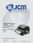
Download Bill Acceptor
Transcript
Bill Acceptor DBV-30X-SU DBV-30X-SD Note 1. It is fobridden to copy the contents of this manual, in whole or in part, except for the user’s personal use, without the express permission of Japan Cash Machine Co., Ltd. 2. The information provided in this manual is subject to change without notice. 3. This manual has been written with care and attention to detail; however, should you find any errors or omissions, please contact Japan Cash machine Co., Ltd. and inform tem of you findings. 4. Please be aware that Japan Cash Machine shall not be held liable by the user for any damages, losses or third party claims arising from any uses of this product. 5. All Company/Manufacturer names used in this manual are the registered trademarks of those companies. Issue Copyright © 2005 Japan Cash Machine Co.Ltd. All rights reserved. 03/2006 Preface/Documentation Conventions etc. Preface Thank you for purchasing the Japan Cash Machine Bill Accepter DBV-30X-SU/DBV-30X-SD (here after referred to as the “DBV-30X unit”). Please read this manual carefully as it explains, step by step, how to use the DBV-30X correctly and safely. Be sure to read this manual and any related materials thoroughly to understand the correct operation and functions of this unit. Documentation Conventions The list below describes the documentation convertions used in this manual. Tis icon indicates situations where slight bodily injury or equipment damage can occur. This icon indecates important information or procedures that must be followed for correct and risk-free unit operation. This icon indicates useful or recommended supplemental information. 1), 2) * This indicates steps ina procedure. Be sure to perform these steps in the order given. This indicates useful or important supplemental inforamation CE Marking Notes The DBV-301-SU is CE marked products. Complies with the following Standard. EN61000-6-1: 2001 EN61000-4-2: 1995+A1 : 1998+A2 : 2001 EN61000-4-3 : 2002+A1 : 2002 EN61000-6-3 : 2001 EN55022 : 1998 (ClassB) 2 Package Contents/Version Information Package Contents The DBV-30X unit’s packing box contains theitems listed below. Please check to confirm that all items shown below have been included. DBV-30X-SX unit (1) Harness (1) MDB Harness (EDP#: 118761) or Optional Harness (EDP#: 118746) MDB Harness Optional Harness Model and Serial No. Information To identify your DBV-30X unit’s model and serial number, see the metallic label attached to the left side of DBV-30X unit. MODEL DBV-301-SU-USA2-2111-D3 SERIAL NO.* * * * * * * * * * DC 24-36V 0.9-0.6A MADE IN JAPAN 3 Table of Contents Table of Contents CHAPTER 1 Model Numbers and Specifications 1-1. Precautions .............................................................................. 1-2 1-2. Main Features ........................................................................... 1-3 1-2-1. Intelligent 3-way LED for Easy field Diagnosis ................................. 1-3 1-2-2. Palm Programmable............................................................................ 1-3 1-2-3. Built in Auditing Functions ................................................................. 1-3 1-2-4. Optional Bill Recycler (RC-10) ........................................................... 1-3 1-3. DBV-30X Naming Composition ............................................... 1-4 1-3-1. Model .................................................................................................... 1-4 1-3-2. Type ...................................................................................................... 1-4 1-4. Component Names .................................................................. 1-5 1-5. System Configuration.............................................................. 1-6 1-5-1. DBV-301 System Configuration.......................................................... 1-6 1-5-1. DBV-302 System Configuration.......................................................... 1-7 1-6. Specifications .......................................................................... 1-8 1-6-1. Technical Specifications ..................................................................... 1-8 1-6-2. Environmental Specifications ............................................................ 1-8 1-6-3. Electrical Specifications ..................................................................... 1-9 1-6-4. Structural Specifications .................................................................... 1-9 1-7. Interface Connector and Pin Assignment............................ 1-10 1-7-1. When using ID-0D3 Interface ............................................................ 1-10 1-7-2. When using ID-003 Interface ............................................................ 1-12 1-8. DIP Switch Settings ............................................................... 1-14 1-8-1. DIP Switch 1 (SW1)............................................................................ 1-14 1-8-2. DIP Switch 2 (SW2)............................................................................ 1-15 1-9. Dimensions ............................................................................ 1-16 1-9-1. DBV-30X-SU with 200 notes cash box ............................................. 1-16 1-9-2. DBV-30X-SU with 300 notes cash box ............................................. 1-17 1-9-3. DBV-30X-SU with 1,000 notes cash box .......................................... 1-18 1-9-4. DBV-30X-SD with 200 notes cash box ............................................. 1-19 1-9-5. DBV-30X-SD with 300 notes cash box ............................................. 1-20 1-9-6. DBV-30X-SD with 1,000 notes cash box .......................................... 1-21 4 Table of Contents CHAPTER 2 Installation and Operation 2-1. Installation ................................................................................ 2-2 2-1-1. Installation ........................................................................................... 2-2 2-1-2. Changing the bill guides ..................................................................... 2-3 2-1-3. Installing the Snack Mask ................................................................... 2-4 2-1-4. Installing the SD Module & SD Bracket ............................................. 2-6 2-2. Operation Flowchart ................................................................ 2-4 2-3. Collecting bills ......................................................................... 2-5 2-4. Clearing Bill Jam ...................................................................... 2-6 2-4-1. When a bill jammed in Transport path ............................................... 2-6 2-4-2. When a bill jammed in Acceptor Head .............................................. 2-6 2-5. Preventive Maintenance ......................................................... 2-7 2-6. Technical Support ................................................................... 2-8 CHAPTER 3 Disassembly Instruction 3-1. How to Remove CPU/Power Supply Board ........................... 3-2 3-1-1. Removing the CPU/Power Sppuly board .......................................... 3-2 3-2-1. Removing the timing belts.................................................................. 3-5 3-2. Disassembly of Pusher Mechanism Assembly ..................... 3-5 3-2-2. Removing the Feed motor and stacker motor .................................. 3-7 3-3-1. Removing the Sensor board .............................................................. 3-9 3-3-2. Removing the O-rings ....................................................................... 3-10 3-3-3. Removing the Feed Small Boards ................................................... 3-12 3-4. Disassembly of Down Guide ................................................. 3-13 3-4-1. Removing the MAG board ................................................................ 3-13 CHAPTER 4 Trouble Shooting and Diagnostics 4-1. Error Code & Reject Code ....................................................... 4-2 4-1-1. Error Codes ......................................................................................... 4-2 4-1-2. Reject Codes........................................................................................ 4-3 4-2. Trouble Shooting ..................................................................... 4-4 4-2-1. General Problems................................................................................ 4-4 4-2-2. Adjustment Problems ......................................................................... 4-5 4-2-3. Communication Problems .................................................................. 4-6 5 Table of Contents 4-3. Diagnostics .............................................................................. 4-7 4-3-1. How to enter the Test Mode ................................................................ 4-7 4-3-2. Feed Motor Forward/Reverse Rotation Test ..................................... 4-7 4-3-3. Stacker Test ......................................................................................... 4-8 4-3-4. Running Test ........................................................................................ 4-9 4-3-5. Continuous Insertion Protect Lever Test ........................................ 4-10 4-3-6. Acceptor Sensor Test ........................................................................ 4-10 4-3-7. Stacker Sensor Test .......................................................................... 4-11 4-3-8. Bill Acceptance Test .......................................................................... 4-12 4-3-9. Stacker Motor Forward/Reverse Rotation Test ............................... 4-13 4-3-10. DIP Switch Test ................................................................................ 4-14 4-4. Sensor, board and motor location ........................................ 4-15 4-5. Cable Diagram ........................................................................ 4-16 4-5-1. DBV-301 Cable Diagram .................................................................... 4-16 4-5-2. DBV-302 Cable Diagram .................................................................... 4-17 CHAPTER 5 Software Download and Adjustment 5-1. Software Download ................................................................. 5-2 5-1-1. Tools Required .................................................................................... 5-2 5-1-2. Initial Setting ........................................................................................ 5-2 5-1-3. Starting Dwonload Program ............................................................... 5-3 5-2. Adjustment .............................................................................. 5-6 5-2-1. Tools Required .................................................................................... 5-6 5-2-2. Installing the Adjustment Program (Cab300.exe) ............................. 5-6 5-2-3. Initial Setting ........................................................................................ 5-6 5-2-4. Adjustment Procedure ........................................................................ 5-7 5-3. Using Palm ............................................................................ 5-13 5-3-1. Items required ................................................................................... 5-13 5-3-2. Installing File Conversion Program (PdbConvEn.CAB) ................. 5-13 5-3-3. Initial Setting required ...................................................................... 5-13 5-3-4. Program Overview ............................................................................ 5-14 5-3-5. Download the software program from Palm ................................... 5-15 5-3-6. Getting the DBV-301 unit’s setting information .............................. 5-19 5-3-7. Execute the Diagnostics ................................................................... 5-20 5-3-8. Get the Accepting Log from DBV-30X unit ...................................... 5-21 5-3-9. Convert the Acceptance log data into the CSV format .................. 5-24 6 Table of Contents CHAPTER 6 Exploded View & Parts List 6-1. Entire Unit ............................................................................... 6-2 see Part Manual 6-1-1. Entire Unit Exploded View ................................................................. 6-2 6-1-2. Entire Unit Parts List ........................................................................... 6-3 6-2. Frame and Up/Down Guide .................................................... 6-4 6-2-1. Frame and Up/Down Guide Exploded View ..................................... 6-4 6-2-2. Frame and Up/Down Guide Parts List ............................................... 6-5 6-3-1. Pusher Mechanism Exploded View .................................................. 6-6 6-3. Pusher Mechanism Assembly .............................................. 6-6 6-3-2. Pusher Mechanism Parts List ............................................................ 6-7 6-4. Cashbox Unit .......................................................................... 6-8 6-4-1. 200 note cashbox Exploded View ..................................................... 6-8 6-4-2. 200 note cashbox Parts List ............................................................... 6-9 6-4-1. 300 note cashbox Exploded View ................................................... 6-10 6-4-2. 300 notes cashbox Parts List ........................................................... 6-11 6-5-1. 1,000 note cashbox Exploded View ................................................ 6-12 6-5-2. 1,000 notes cashbox Parts List ........................................................ 6-13 6-5. SD Module 6-5-1. SD Module Exploded View 6-5-2. SD Module Parts List 6-6. Snack Mask 6-6-1. Snack Mask Exploded View 6-6-2. Snack Mask Parts List CHAPTER 7 Optional Bill Recycler Unit (RC-10) 7-1. Precautions .............................................................................. 7-2 7-2. RC-10 Component Names ....................................................... 7-3 7-3. Specifications .......................................................................... 7-4 7-3-1. Technical Specifications ..................................................................... 7-4 7-3-2. Environmental Specifications ............................................................ 7-4 7-3-4. DIP Switch Settings ............................................................................. 7-5 7 Table of Contents 7-6. Installation and Operation ....................................................... 7-8 7-6-1. Installing/Removing the RC-10 unit ................................................... 7-8 7-6-2. Installing/Removing the Cash Box .................................................... 7-9 7-6-3. Autoloading Bills ............................................................................... 7-10 7-6-4. Stacking Bills ..................................................................................... 7-11 7-6-5. Dispensing Bill .................................................................................. 7-12 7-6-6. Clearing JAM Bill ............................................................................... 7-13 7-7. Diagnostic Code and Wiring Diagram .................................. 7-15 7-7-1. LED Diagnostic Codes ...................................................................... 7-15 7-7-2. Wiring Diagram .................................................................................. 7-16 7-8. Disassembly Instruction ....................................................... 7-17 7-8-1. Removing Side Cover ....................................................................... 7-17 7-8-2. Changing Recycle Board .................................................................. 7-18 7-8-3. Changing PT Board/LED Board ....................................................... 7-19 7-8-5. Changing Encoder Board ................................................................. 7-21 7-9. Exploded View and Parts List ............................................... 7-22 7-9-1 Exploded View ................................................................................... 7-22 7-9-2. RC-10 Parts List ................................................................................. 7-23 8 Bill Acceptor DBV-30X Service Manual Chapter 1 Model Numbers & Specifications 1-1. 1-2. Precautions Main Features 1-3. 1-4. DBV-30X Naming Composition Component Names 1-5. 1-6. System Configuration Specifications 1-7. 1-8. Interface Connector and Pin Assignment DIP Switches Settings 1-9. Dimensions Issue 08/2007 DBV-30X Service Manual CHAPTER 1 1-1. Precautions 1-2 - Do not insert a torn, folded, or wet bill, as this may cause bill jam inside the unit. Do not expose the unit to water. The unit contains several precision electronic devices - which can be damaged if water or any liquid is sprayed or spilled into the unit. Do not install the unit in a dusty environment. Dust may affect the sensor performance. - When installing the unit, be sure to turn the power OFF. When installing the DBV-30X unit, tighten mounting nuts until snug. DO NOT overtighten. - To avoid the electrical hazards and equipment damage, be sure to use only specified voltage. © 2006 Japan Cash Machine Co.Ltd. DBV-30X Service Manual 1-2. Main Features The DBV-30X has the following features. CHAPTER 1 1-2-1. Intelligent 3-way LED for Easy field Diagnosis DBV-30X unit has intelligent 3-way LED. It blinks depending on the error. Color of LED and the number of blinking shows the error type. 1-2-2. Palm Programmable Palm can be connected to DBV-30X unit to download the software program, execute the diagnostic test and get the acceptance log data. For details about connecting to Palm, refer to 5-3. Using Palm. 1-2-3. Built in Auditing Functions DBV-30X unit has the following built-in functions. - Jam Rate - Acceptance Rate - Internal Diagnostics - Money Auditing 1-2-4. Optional Bill Recycler (RC-10) DBV-301-SU unit can attach an optional bill recycler unit (RC-10). It is the first bill acceptor for the vending industry with built-in intelligence for recycling of notes. © 2006 Japan Cash Machine Co.Ltd. 1-3 DBV-30X Service Manual 1-3. DBV-30X Naming Composition 1-3-1. Model CHAPTER 1 DBV - 3 0 1 (1) (2) (3) (4) (1) Model Name - SU (5) (2) Series Name (3) CPU Board Type 0: JCM Standard (4) Power supply 0: DC12V 1: DC24V 2: AC117V (5) Stacker Type SU: Upward vertical stacking SD: Downward vertical stacking 1-3-2. Type * * * - * * * * * - ** (6) (7) (8) (9) (10) (11) (12) (6) Country Code *1 3-digit ISO code Ex RUS - Russia (7) Cash Box Capacity 2: 200 Notes Cash Box 3: 300 Notes Cash Box 5: 500 Notes Cash Box A: 1000 Notes Cash Box (8) Bezel Type 1: JCM Standard Bezel (SU/SD) 2: Snack Mask (SU/SD) 3: Euro Bezel (SU) 4: Euro Bezel (SD) 1-4 © 2006 Japan Cash Machine Co.Ltd. . DBV-30X Service Manual (9) Guide Width 1: 67 mm 3: 71 mm CHAPTER 1 4: 73mm (10)Cash Box Type 1: Upward bill ejection box (11)Recycle Type (Optional) 0: without bill recycler unit 1: with bill recycler unit (12)Interface Type *1 D3: ID-0D3 (MDB interface) 03: ID-003 (Serial interface) 44: ID-044 (OEM interface) *1 For another interface, please contact JCM. © 2006 Japan Cash Machine Co.Ltd. 1-5 DBV-30X Service Manual 1-4. Component Names CHAPTER 1 Cash box cover Cash box release lever RC-10 Connecotr Cash box Communication Port Faceplate Indication LED AC117V Power Supply Connector DIP Switch 1 (For DBV-302 Only) Interface Connector DIP Switch 2 Acceptor head Condition LED 1-6 Acceptor head release lever © 2006 Japan Cash Machine Co.Ltd. DBV-30X Service Manual 1-5. System Configuration 1-5-2. DBV-300 System Configuration Communication Port Interface Connector Palm(R) Tungsten C *1 Harness (EDP# 116490, Part# 3280-03-15) Download Adapter (EDP# G00171) PC (OS: Windows(R) 98 SE/2000) *2 JCM Power Supply Unit (EDP# 116477, Part# VM300) Host Machine Optional Harness (EDP# 118746) *1 Palm can be connected to download a software, perform the diagnostics and *2 collect the accepting log data. PC can be connected to download software and perform an adjustment. For details about software downloading and adjustment, refer to Chapter 5. © 2006 Japan Cash Machine Co.Ltd. 1-7 CHAPTER 1 DBV-300 DBV-30X Service Manual Communication Port Interface Connector DBV-301 RC-10 Connector 1 CHAPTER 1-5-2. DBV-301 System Configuration JCM’ s *2 OPTIPAY CC Optional Bill Recycler Unit (RC-10)*1 Palm(R) Tungsten C*3 Harness (EDP# 116490, Part# 3280-03-15) Download Adapter (EDP# G00171) PC (OS: Windows(R) 98 SE/2000)*4 JCM Power Supply Unit (EDP# 116480, Part# VM301) or Host Machine Optional Harness (EDP# 118746) *1 MDB Harness (EDP# 118761) The optional bill recycler unit (RC-10) can be installed with only DBV-301 unit which is using MDB interface, and which is connecting with JCM’s Coin Changer *2 (OPTIPAY CC). For details about RC-10 unit, refer to Chapter 7. For details about JCM’s Coin Changer (OPTIPAY CC), please contact JCM. *3 Palm can be connected to download a software, perform the diagnostics and *4 collect the accepting log data. PC can be connected to download software and perform an adjustment. For details about software downloading and adjustment, refer to Chapter 5. 1-8 © 2006 Japan Cash Machine Co.Ltd. DBV-30X Service Manual 1-5-3. DBV-302 System Configuration Communication Port Interface Connector Palm(R) Tungsten C *1 Harness (EDP# 116490, Part# 3280-03-15) Download Adapter (EDP# G00171) PC (OS: Windows(R) 98 SE/2000) *2 Host Machine Optional Harness (EDP# 118746) *1 Palm can be connected to download a software, perform the diagnostics and collect the accepting log data. *2 PC can be connected to download software and perform an adjustment. For details about software downloading and adjustment, refer to Chapter 5. © 2006 Japan Cash Machine Co.Ltd. 1-9 CHAPTER 1 DBV-302 DBV-30X Service Manual 1-6. Specifications 1-6-1. Technical Specifications Width (min. 65 - max. 72 mm) *1 Length (min. 120 - max. 160 mm) Refer to the software Information Sheet Refer to the software Information Sheet Approx. 2 seconds (from bill insertion to credit signal output) Approx. 3 seconds (from bill insertion to bill stack completion) 200 Notes Cash Box 300 Notes Cash Box 500 Notes Cash Box 1,000 Notes Cash Box Pulse/MDB *2/Serial 1 Bill Condition LED (Red/Yellow/Green) (Rear) Indication LED (Green) (Front) CHAPTER 1 Bill Accepted Insertion Direction Acceptance Rate Processing Speed Cash Box Capacity Interface Escrow LED *1 Bills narrower than 65 mm (width) or wider than 71mm (width) will need special *2 bill guides. Contact your JCM sales representative for details. When using MDB interface, the optional bill recycler unit (RC-10) can be attached. For details about RC-10 unit, refer to Chapter 7. 1-6-2. Environmental Specifications Operation Temperature *1 Storage Temperature Operation Humidity *1 Storage Temperature Light disturbance Installation *1 o o o o -15 C to 60 C -20 C to 60 C +15% to 95% RH (no condensing) +15% to 95% RH (no condensing) Direct sunlight shall be avoided Indoor and Outdoor (not exposed to wind and weather) Be sure to satisfy the following temperature humidity conditions. Additional Range Range of operation temperature/humidity Additional Range 1-10 © 2006 Japan Cash Machine Co.Ltd. DBV-30X Service Manual 1-6-3. Electrical Specifications Power Consumption DBV-301 DC24V (+5% ) 2.5A (Recommended) Standby: 0.3A In Operation: 0.6A (Max: 1.5A) Standby: 0.2A In Operation: 0.4A (Max: 0.9A) DBV-302 AC117V AC90V to AC123V (50/60Hz) Standby: 0.07A In Operation: 0.16A (Max: 0.45A) 1-6-4. Structural Specifications Mounting Weight Outline Dimentions Holizontal Mounting Approx. 1.2kg (with 200 Note Cash Box) Refer to 1-9. Dimensions © 2006 Japan Cash Machine Co.Ltd. 1-11 CHAPTER 1 Power Supply DBV-300 DC12V (+5% ) 2.5A (Recommended) DBV-30X Service Manual 1-7. Interface Connector and Pin Assignment CHAPTER 1 Header(Dual Light Angle Type): 702290-3007 (US MOLEX) 1 2 3 4 5 6 7 8 9 10 Recommended Housing: 70066-0113 (US MOLEX) Clip (Dual Type): 70013-0018 (US MOLEX) Terminal: 70058-0204 (US MOLEX) Recommended Wire: String AWG#24 to 26 11 12 13 14 15 16 17 18 1-7-1. When using ID-0D3 (MDB) Interface DBV-301 P in No. 1 2 3 4 5 6 7 8 9 10 11 12 13 14 15 16 17 18 *1 1-12 S igna l Na m e VDD1 VSS1 NC NC T XD2 RXD2 SG2 NC NC NC NC NC NC NC NC NC NC NC I/O *1 OUT IN Function DC24V GND Not Connected Not Connected Photo-coupler: Output Signal Line from Bill Acceptor Photo-coupler: Input Signal Line from Bill Acceptor Photo-coupler: Signal Ground Not Connected Not Connected Not Connected Not Connected Not Connected Not Connected Not Connected Not Connected Not Connected Not Connected Not Connected I/O (input/output) is the term from bill acceptor’s side. © 2006 Japan Cash Machine Co.Ltd. DBV-30X Service Manual Photo Coupler-isoration Input/Output Circuit ACCEPTOR HOST CONTROLLER CHAPTER 1 © 2006 Japan Cash Machine Co.Ltd. . 1-13 DBV-30X Service Manual 1-7-2. When using ID-003 (Serial) Interface DBV-300 CHAPTER 1 Pin No. 1 2 3 4 5 6 7 8 9 10 11 12 13 14 15 16 17 18 *1 *2 Signal Name NC NC VDD VSS TXD2 RXD2 SG2 TXD1 RXD1 SG TXD0 RXD0 NC NC NC NC NC NC I/O *1 OUT IN OUT IN OUT IN Function Not Connected Not Connected DC12V DC12V GND Photo-coupler: Output Signal Line from Bill Acceptor *3 Photo-coupler: Input Signal Line from Bill Acceptor *3 Photo-coupler: Signal Ground *3 RS-232C: Output Signal Line from Bill Acceptor *3 RS-232C: Input Signal Line from Bill Acceptor *3 RS-232C/TTL: Signal Ground *3 TTL: Output Signal Line from Bill Acceptor *3 TTL: Input Signal Line from Bill Acceptor *3 Not Connected Not Connected Not Connected Not Connected Not Connected Not Connected I/O (input/output) is the term from bill acceptor’s side. To avoid the electrical hazards and equipment damage, be sure to use only specified voltage. *3 The serial I/F level (Photo-coupler/RS-232C/TTL) can be selected with DIP Switch 2. For details, refer to 1-8. DIP Switch Setting. DBV-302 Pin No. 1 2 3 4 5 6 7 8 9 10 11 12 13 14 15 16 17 18 *1 *2 Signal Name NC NC NC NC TXD2 RXD2 SG2 TXD1 RXD1 SG TXD0 RXD0 NC NC NC NC NC NC I/O *1 OUT IN OUT IN OUT IN Function Not Connected Not Connected Not Connected Not Connected Photo-coupler: Output Signal Line from Bill Acceptor *2 Photo-coupler: Input Signal Line from Bill Acceptor *2 Photo-coupler: Signal Ground *2 RS-232C: Output Signal Line from Bill Acceptor *2 RS-232C: Input Signal Line from Bill Acceptor *2 RS-232C/TTL: Signal Ground *2 TTL: Output Signal Line from Bill Acceptor *2 TTL: Input Signal Line from Bill Acceptor *2 Not Connected Not Connected Not Connected Not Connected Not Connected Not Connected I/O (input/output) is the term from bill acceptor’s side. The serial I/F level (Photo-coupler/RS-232C/TTL) can be selected with DIP Switch 2. For details, refer to 1-8. DIP Switch Setting. 1-14 © 2006 Japan Cash Machine Co.Ltd. DBV-30X Service Manual Photo-coupler isolation Input/Output Circuit ACCEPTOR HOST CONTROLLER CHAPTER 1 RS-232C Input/Output Circuit ACCEPTOR HOST CONTROLLER TTL Input/Output Circuit ACCEPTOR HOST CONTROLLER © 2006 Japan Cash Machine Co.Ltd. 1-15 DBV-30X Service Manual 1-7-3. When using ID-002 (Pulse) Interface DBV-300 CHAPTER 1 Pin No. 1 2 3 4 5 6 7 8 9 10 11 12 13 14 15 16 17 18 Signal Name NC NC VDD1 VSS1 NC NC NC NC NC SG /VEND NC NC /ENABLE NC /BUSY /ABN /FULL *1 I/O *1 OUT IN OUT OUT OUT Function Not Connected Not Connected DC12V DC12V GND Not Connected Not Connected Not Connected Not Connected Not Connected Signal Ground Accepted denomination Signal Not Connected Not Connected Bill Inhibit (Hi) / Accept (Lo) Signal Not Connected Acceptor Operating Signal Acceptor Error Signal Cash Box Full signal Active Lo Lo Lo Lo Lo I/O (input/output) is the term from bill acceptor’s side. DBV-301 Pin No. 1 2 3 4 5 6 7 8 9 10 11 12 13 14 15 16 17 18 *1 1-16 Signal Name VDD1 VSS1 NC NC NC NC NC NC NC SG /VEND NC NC /ENABLE NC /BUSY /ABN /FULL I/O *1 OUT IN OUT OUT OUT Function DC24V DC24V GND Not Connected Not Connected Not Connected Not Connected Not Connected Not Connected Not Connected Signal Ground Accepted denomination Signal Not Connected Not Connected Bill Inhibit (Hi) / Accept (Lo) Signal Not Connected Acceptor Operating Signal Acceptor Error Signal Cash Box Full signal Active Lo Lo Lo Lo Lo I/O (input/output) is the term from bill acceptor’s side. © 2006 Japan Cash Machine Co.Ltd. DBV-30X Service Manual Sequence Chart Accept Bill CHAPTER 1 DISABLE/ ENABLE BUSY VEND ABN FULL DISABLE DRAWING BILL and VALIDATION STACKING VEND OUTPUT STAND BY INSERT BILL STAND BY Return Bill DISABLE/ ENABLE BUSY VEND ABN FULL DISABLE DRAWING BILL and VALIDATION RETRUN BILL DISABLE(INHIBIT) INSERT BILL STAND BY © 2006 Japan Cash Machine Co.Ltd. 1-17 DBV-30X Service Manual Stack Bill CHAPTER 1 DISABLE/ ENABLE BUSY VEND ABN FULL DISABLE DRAWING BILL and VALIDATION STACKING VEND OUTPUT REJECT BILL JAMMED BILL STACKER FULL INSERT BILL STAND BY Jam Bill DISABLE/ ENABLE BUSY VEND ABN FULL DISABLE DRAWING BILL and VALIDATION STAND BY INSERT BILL REMOVED BILL STAND BY 1-18 © 2006 Japan Cash Machine Co.Ltd. DBV-30X Service Manual 1-8. DIP Switch Settings DBV-30X unit have 2 DIP Switches (SW 1/SW 2). They are located on the left side of CHAPTER 1 DBV-30X unit. Verify the DIP switch settings before installing the DBV-30X unit. The DIP switch settings are determined by the software. See software specifications provided sepa- OFF 1 2 3 DIP Swich 2 4 5 6 7 8 OFF 1 2 3 4 DIP Swich 1 5 6 7 8 rately for DIP switch settings of your software. 1-8-1. DIP Switch 1 (SW1) SW 1 sets the accepted Denomination and mode. Depending on the software, the denomination settings will differ. Refer to the software specifications. No. SW1-1 SW1-2 SW1-3 SW1-4 SW1-5 SW1-6 SW1-7 SW1-8 Function Denomination 1 Denomination 2 Denomination 3 Denomination 4 Denomination 5 Denomination 6 Denomination 7 Mode Setting ON OFF Inhibit Accept Test Mode *1 Normal Mode *1 For details about Test Mode, refer to 4-3. Diagnostics. © 2006 Japan Cash Machine Co.Ltd. 1-19 DBV-30X Service Manual 1-8-2. DIP Switch 2 (SW2) CHAPTER 1 DIP Switch 2 sets the Communication method. For details, refer to the software specifications. ID-0D3 (MDB) interface No. SW2-1 SW2-2 SW2-3 SW2-4 SW2-5 SW2-6 SW2-7 SW2-8 Function - ON OFF Always OFF ID-002 (Pulse) interface No. SW2-1 OFF ON OFF ON SW2-3 OFF ON OFF ON SW2-5 SW2-6 SW2-7 SW2-8 SW2-2 OFF OFF ON ON SW2-4 OFF OFF ON ON Always OFF Always OFF Always OFF Always ON Function PULSE WIDTH 50ms/300ms 50ms/50ms 80ms/120ms 150ms/180ms PULSE COUNT 1 Pulse 4 Pulse 10 Pulse 20 Pulse - ID-003 (Serial) interface No. SW 2-1 1-20 SW 2-2 OFF OFF ON OFF ON SW 2-3 SW 2-4 SW 2-5 SW 2-6 SW 2-7 SW 2-8 OFF ON OFF Always OFF Always OFF Always OFF Always OFF Always OFF Always OFF Function Se ria l I/F Le ve l Photo-coupler Isoration TTL RS-232C RS-232C - © 2006 Japan Cash Machine Co.Ltd. 59.1 15.5 10.5 (Bill Insertion Slot) 22 8.4 2-5 50.8 +0.1 84 +0.1 86 98.2 88 18 4 33 41.5 72 113.5 245.6 107 14.6 116 +0.1 134.1 10.1 Unit : mm 174.3 59.7 11.6 4-5 1-9-1. DBV-30X-SU with 200 Notes Cash Box CHAPTER 1 1-9. Dimensions DBV-30X Service Manual © 2006 Japan Cash Machine Co.Ltd. 1-21 18 4 59.1 15.5 10.5 (Bill Insertion Slot) 22 8.4 2-5.4 50.8 +0.1 84 +0.1 86 98.2 88 44 107 14.6 116 +0.1 134.1 10.1 33 41.5 72 127 Unit: mm 249.6 174.3 178.3 2-5.4 1-22 11.6 71.3 1-9-2. DBV-30X-SU with 300 Notes Cash Box CHAPTER 1 DBV-30X Service Manual © 2006 Japan Cash Machine Co.Ltd. © 2006 Japan Cash Machine Co.Ltd. 10.7 (Bill Insertion Slot) 22 8.4 98.2 86 84 ±0.1 50.8 ±0.1 2-5.4 44 107 14.6 15.5 59.1 2-5.4 116 10.1 33 41.5 72 153.5 Unit: mm 249.6 174.3 11.6 88 18 4 178.3 71.3 CHAPTER 1 134.1 1-9-3. DBV-30X-SU with 500 Notes Cash Box DBV-30X Service Manual 1-23 18 4 59.1 15.5 10.5 (Bill Insertion Slot) 22 8.4 2-5.4 50.8 0.1 84 0.1 86 98.2 88 44 33 41.5 72 250 179.3 183.3 107 14.6 116 0.1 134.1 10.1 Unit : mm 249.6 2-5.4 1-24 11.6 66.3 1-9-4. DBV-30X-SU with 1,000 Notes Cash Box CHAPTER 1 DBV-30X Service Manual © 2006 Japan Cash Machine Co.Ltd. 90 98.2 86 84 +0.1 +0.1 2-5.4 14.6 107 10.1 +0.1 134.1 116 59.1 22 $KNN+PUGTVKQP5NQV 15.5 4 18 41.5 33 72 113.5 Unit : mm 11.6 71.3 174.3 8.4 CHAPTER 1 269.1 2-5.4 1-9-5. DBV-30X-SD with 200 Notes Cash Box DBV-30X Service Manual © 2006 Japan Cash Machine Co.Ltd. 1-25 90 98.2 86 84 +0.1 50.8 +0.1 2-5.4 22 $KNN+PUGTVKQP5NQV 59.1 15.5 18 10.1 134.1 116 +0.1 107 8.4 Unit: mm 11.6 2-5.4 1-26 1-9-6. DBV-30X-SD with 300 Notes Cash Box CHAPTER 1 DBV-30X Service Manual © 2006 Japan Cash Machine Co.Ltd. 2-5.4 86 2-5.4 50.8 ±0.1 4 18 12.6 116 ±0.1 24.5 10.7 (Bill Insertion Slot) 17.1 107 84 ±0.1 61.6 15.5 1.6 33 41.5 72 153.5 Unit: mm 14.1 174.3 5.9 73.8 178.3 103.2 CHAPTER 1 271.7 1-9-7. DBV-30X-SD with 500 Notes Cash box and SD Bracket DBV-30X Service Manual © 2006 Japan Cash Machine Co.Ltd. 1-27 107.2 86 0.1 50.8 0.1 6-φ5.4 24.5 $KNN+PUGTVKQP5NQV 61.6 15.5 12.6 0.1 3.9 18 17.1 4 41.5 33 1.6 72 1-9-8. DBV-30X-SD with 1,000 Notes Cash Box and SD Bracket 250 Unit : mm 14.1 68.8 179.3 183.3 271.7 1-28 107 CHAPTER 1 DBV-30X Service Manual © 2006 Japan Cash Machine Co.Ltd. 85 90 98.2 84.7 84 50.8 2-5.4 59.1 15.5 14.2 4.4 107.3 27 10.1 134.1 116 22 9.5 (Bill Insertion Slot) 34.5 13 19.6 24.4 91.1 137.6 132.6 Unit: mm 11.6 71.3 174.3 8.4 CHAPTER 1 269.1 2-5.4 1-9-9. DBV-30X-SD with 200 Notes Cash Box and Lock Module DBV-30X Service Manual © 2006 Japan Cash Machine Co.Ltd. 1-29 85 90 98.2 84.7 84 ±0.1 50.8 ±0.1 2-5.4 27 10.1 134.1 116 ±0.1 59.1 15.5 22 9.5 (Bill Insertion Slot) 14.2 4.4 107.3 8.4 34.5 13 19.6 24.4 91.1 137.6 146.1 Unit: mm 269.1 11.6 71.3 2-5.4 1-30 174.3 178.3 1-9-10. DBV-30X-SD with 300 Notes Cash Box and Lock Module CHAPTER 1 DBV-30X Service Manual © 2006 Japan Cash Machine Co.Ltd. 12.6 116 ±0.1 2-5.4 2-5.4 50.8±0.1 61.6 15.5 4 18 84±0.1 24.5 10.7 (Bill Insertion Slot) 17.1 107 5.9 1.6 33 41.5 72 153.5 Unit: mm 14.1 174.3 86 73.8 178.3 103.2 CHAPTER 1 1-9-11. DBV-30X-SD with 500 Note Cash Box, SD Bracket and Lock Module DBV-30X Service Manual © 2006 Japan Cash Machine Co.Ltd. 1-31 303.1 85 90 103.2 ±0.1 ± 2-5.4 24.5 9.5 (Bill Insertion Slot) 61.6 15.5 12.6 ±0.1 116 14.2 4.4 27 5.9 34.5 13 1.6 19.6 24.4 91.1 137.6 269.1 Unit: mm 271.7 4-5.4 1-9-12. DBV-30X-SD with 1,000 Notes Cash Box, SD Bracket and Lock Module 14.1 68.8 183.3 1-32 107.3 CHAPTER 1 DBV-30X Service Manual © 2006 Japan Cash Machine Co.Ltd. Bill Acceptor DBV-30X Service Manual Chapter 2 Installation & Operation 2-1. Installation 2-2. 2-3. Operation Flowchart Collecting Bills 2-4. Clearing Bill Jam 2-5. Preventive Maintenance 2-6. Technical Support Issue 08/2007 DBV-30X Service Manual 2-1. Installation 2-1-1. Installation CHAPTER 2 1) Remove the cash box and down guide. 2) Insert the DBV-30X unit into the panel cut Vending machine out from behind the Vending machine’s door. 3) Insert the attachment screws into the DBV-30X unit’s four insertion slots. Use a screw driver to tighten each attachment screws and secure the DBV-30X unit in place. 4) Install the down guide and cash box. 2-2 © 2006 Japan Cash Machine Co., Ltd. DBV-30X Service Manual 2-1-2. Changing the bill guides 1) Remove the cash box and down guide. CHAPTER 2 SB Guide Left SB Guide Right 2) Remove the SB guide Left/Right in the arrow (1) and (2) direction. 3) Remove the faceplate. 4) Remove the FB guide in the arrow (3) direction. FB Guide © 2006 Japan Cash Machine Co., Ltd. 2-3 DBV-30X Service Manual 2-1-3. Installing the Snack Mask CHAPTER 2 1) Remove the standard faceplate. 2) Place the Window Spacer on the DBV30X unit. 3) Then place the FP Bracket on it. 2-4 © 2006 Japan Cash Machine Co., Ltd.. DBV-30X Service Manual 4) Insert the attachment screws into four (4) insertion slots are located on the rear of the DBV-30X unit. Use a screw driver to tighten each attachment screws and secure them in place. CHAPTER 2 5) Place the Snack Mask and insert the attachment screws into three (3) insertion slots. Use a screw driver to tighten each attachment screws and secure the snack mask in place. © 2006 Japan Cash Machine Co., Ltd. 2-5 DBV-30X Service Manual 2-1-4. Installing the SD Module and SD Bracket 1) Prepare the SD Module. CHAPTER 2 - Be sure not to loose the spring. 2) Remove the cash box and take off the box stopper from the DBV-30X unit. Box Stopper 3) Turn the DBV-30X unit upside down and slide the DBV-30X unit backward until it is locked. 2-6 © 2006 Japan Cash Machine Co., Ltd.. DBV-30X Service Manual - The step 4) need to be followed only when attaching the 500 Note Cashbox and 1000 Note Cash Box. 4) Attach the SD Bracket and insert the attachment screws into three (3) insertion slots. Use a screw driver to tighten each attachment screws and secure them in place. CHAPTER 2 © 2006 Japan Cash Machine Co., Ltd. 2-7 DBV-30X Service Manual 2-1-5. Installing the Lock Module 1) Attach the Lock Frame C to the bottom of the SD module and insert the attachment screws into two (2) insertion slots. Use a screw driver to tighten each attachement screws and secure the lock module in place. Screws CHAPTER 2 Lock Frame C Screws SD Module Bottom view of the SD module Top View of the SD module 2) Attach the Lock Module to the SD Module and insert the attachment screws into three (3) insertion slots. Use a screw driver to tighten each attachment screws and secure the lock module in place. 3) Turn the DBV-30X unit upside down and slid backward until it is locked to attach the Lock Assy . 2-8 © 2006 Japan Cash Machine Co., Ltd.. DBV-30X Service Manual - Even when installing the lock module to DBV-30X-SU type unit, the SD module is also required. Follow the steps above to install the lock module to the DBV-30X-SU type unit. CHAPTER 2 © 2006 Japan Cash Machine Co., Ltd. 2-9 DBV-30X Service Manual 2-1-6. Installing the Waterproof Kit CHAPTER 2 0.04 1) Remove the base cover and the cashbox from the DBV-30X unit. 2) Attach the base cover, gasket 1 and gasket 2 to the DBV-30X. 3) Attach the top cover sliding until it clicks. - When installing the RC-10 unit, this step does not required. 2-10 © 2006 Japan Cash Machine Co., Ltd.. DBV-30X Service Manual 2-2. Operation Flowchart CHAPTER 2 © 2006 Japan Cash Machine Co., Ltd. 2-11 DBV-30X Service Manual 2-3. Collecting Bills 1) Pull the cash box release lever in the arrow (1) direction. 2) Lift the cash box in the CHAPTER 2 arrow (2) direction and remove it. 3) Open the cash box cover and remove the bills. 2-12 © 2006 Japan Cash Machine Co., Ltd.. DBV-30X Service Manual 2-4. Clearing Bill Jam 2-4-1. When a bill jammed in Transport path 1) Remove the cash box (Refer to “2-3. Collecting Bills”). 2) Remove the jammed bill. CHAPTER 2 2-4-2. When a bill jammed in Acceptor Head 1) Pull out the down guide, raising the acceptor head release lever. 2) Remove the jammed bill. Down guide Acceptor head release lever © 2006 Japan Cash Machine Co., Ltd. 2-13 DBV-30X Service Manual 2-5. Preventive Maintenance It is important to keep the bill path, rollers, and belts clean. The sensor lenses are transparent, and made of polymer material. Handle them with care. Use a soft lint-free cloth or cotton bud to wipe out dirt and stain on the surface of magnetic and optical sensors, rollers and belts. Repeat the cleaning process as needed until the transport path is free of contaminants. - Do not use alcohol or thinner for cleaning. CHAPTER 2 - JCM does not recommend cleaning cards, cleaning pads, or cleaning solutions of any kind. Sensor Roller Belt Up Guide and Stacker Section Down Guide Cash Box 2-14 © 2006 Japan Cash Machine Co., Ltd.. DBV-30X Service Manual 2-6. Technical Support -JapanJapan Cash Machine Co., Ltd. (Headquarters) No. 3-15, Nishiwaki 2-Chome, Hirano-ku, Phone: +81-66-703-8406 Fax: +81-66-704-7843 Osaka, 547-0035, Japan URL: www.jcm-hq.co.jp Phone: +1-702-651-0000 925 Pilot Road, Las Vegas, NV 89119 U.S.A. Fax: +1-702-644-5512 e-mail: [email protected] URL: www.jcmamerican.com - Europe, Russia, Middle East, Africa Japan Cash Machine Germany GmbH Phone: +49-211-530-645-60 Mündelheimer Weg 60 D-40472 Düsseldorf Germany Fax: +49-211-530-645-85 e-mail: [email protected] URL: www.jcm-germany.com - UK & Ireland JCM United Kingdom Ltd. Phone: +44-(0)870-770-2863 Unit B, Third Avenue, Denbigh West Business Park Fax: +44 (0) 190-837-7834 e-mail: [email protected] Bletchley, Milton Keynes, Buckinghamshire MK1 1EJ, UK URL: www.jcm-uk.com - Asia JCM Gold (HK) Ltd. Unit 1-7, 3/F., Favor Industrial Centre Phone: +852-2429-7187 Fax: +852-2929-7003 2-6 Kin Hong Street, Kwai Chung, N.T. Hong Kong e-mail: [email protected] URL: www.jcmgold.com.hk © 2006 Japan Cash Machine Co., Ltd. 2-15 CHAPTER 2 - Americas & Oceania JCM American Corporation DBV-30X Service Manual CHAPTER 2 NOTE 2-16 © 2006 Japan Cash Machine Co., Ltd.. Bill Acceptor DBV-30X-SU DBV-30X-SD CHAPTER 3 Contents Disassembly Instruction 3-1. How To Remove the CPU/Power Supply Board 3-2. How To Remove the Pusher Mechanism 3-3. Disassembly of Up Guide 3-4. Disassembly of Down Guide Issue Copyright © 2005 Japan Cash Machine Co.Ltd. All rights reserved. 03/2006 CHAPTER 3 Disassembly Instruction 3-1. How to Remove CPU/Power Supply Board 3-1-1. Removing the CPU/Power Sppuly board Cash Box Releace Lever 1) Pull the cash box release lever in the arrow (1) direction and remove the cash box in the arrow (2) direction. Cash Box 2) Pull out the down guide lifting the acceptor head release lever. Acceptor Head Release Lever 3-2 CHAPTER 3 Disassembly Instruction 3) Slide upward the base cover to remove the cover. 4) Remove 4 screws to remove the face plate. 5) Remove 6 screws and disconnect 4 connectors. 6) Remove the board assembly in the arrow direction. 3-3 CHAPTER 3 Disassembly Instruction 7) Disconnect the connector from the CPU board. Release the lock and remove the flexible connector. - When disconnecting the flexible connector, be sure to handle it carefully otherwise the nail of connector breaks. 8) Disconnect the connector and separate the CPU board and the Power Supply board. CPU Board Power Supply Board 3-4 CHAPTER 3 Disassembly Instruction 3-2. Disassembly of Pusher Mechanism Assembly 3-2-1. Removing the timing belts 1) Remove the CPU board and power supply board Refer to 3-1. How to Remove Power Supply/CPU Board. 2) Remove the SB guide Left/Right in the arrow (1) direction and the arrow (2) direction. SB Guide Left SB Guide Right 3) Remove the front FB guide in the arrow (3) direction. FB Guide 3-5 CHAPTER 3 Disassembly Instruction 4) Remove the screw and remove the pusher mechanism assembly in the arrow direction. 5) Remove 2 timing belts and rollers from the pusher mechanism assembly. - When removing the timing belts from the pusher mechanism, be sure not to loose the rollers. 3-6 CHAPTER 3 Disassembly Instruction 3-2-2. Removing the Feed motor and stacker motor 1) Remove 2 E-rings and pull out the shaft from pusher plate. 2) Slide the pusher plate in the arrow direction and remove the plate. 3) Remove the E-ring and pull out the shaft from the pusher arm. Remove 2 spacers. 3-7 CHAPTER 3 Disassembly Instruction 4) Lift the pusher arm and remove 5 screws and remove the motor guide. 5) Remove the feed motor and stacker motor from the motor guide. 3-8 CHAPTER 3 Disassembly Instruction 3-3. Disassembly of Up Guide 3-3-1. Removing the Sensor board 1) Remove the pusher mechanism assembly Refer to 3-2. Disassembly of Pusher Mechanism Assembly. 2) Remove 2 screws and pull out the up guide. 3) Pull out 2 shafts and remove 4 gears. 3-9 CHAPTER 3 Disassembly Instruction 4) Remove 2 screws and remove the Sensor board. 5) Release the lock and remove the flexible connector from the sensor board. - When disconnecting the flexible connector, be sure to handle it carefully otherwise the nail of connector breaks. Sensor Board 3-3-2. Removing the O-rings 1) Pull out 2 shafts and remove 2 gears. 3 - 10 CHAPTER 3 Disassembly Instruction 2) Pull out the shaft and remove 2 gears. 3) Pull out the shaft and remove 2 gears, 2 springs, 2 bushings, 2 polly sliders and actuator. 4) Remove 2 O-rings from each gears. 3 - 11 CHAPTER 3 Disassembly Instruction 3-3-3. Removing the Feed Small Boards 1) Remove the screws and both Left and Right Feed Small Board in the allow direction 3 - 12 CHAPTER 3 Disassembly Instruction 3-4. Disassembly of Down Guide 3-4-1. Removing the MAG board 1) Remove the screw to remove the down guide cover in the arrow direction. 2) Remove 2 screws from the MAG board. 3) Disconnect the connector and remove the MAG board. MAG Board 3 - 13 Bill Acceptor DBV-30X-SU DBV-30X-SD CHAPTER 4 Contents Trouble Shooting and Diagnostics 4-1. 4-2. 4-3. 4-4. 4-5. Error Codes and Reject Codes Trouble Shooting Diagnostics Sensor, Board and Motor Locations Cable Diagrams Issue Copyright © 2005 Japan Cash Machine Co.Ltd. All rights reserved. 03/2006 CHAPTER 4 Trouble Shooting and Diagnostics 4-1. Error Code & Reject Code This section explains the error code and the reject code. The following tables lists the Condition LED's color, the number of blinking and their meanings. When an error and rejection occurs, check the Condition LED’s color and the number of blinking and detect the cause. 4-1-1. Error Codes Condition Discription Solution LED Cash box is full. Collect the bill. Refer to R Y G Stacker Full 2-3. Collect the bill. 1 2 Stacker JAM Remove the Jam bill. Refer to 2-4. Acceptor JAM 3 Clearing Bill Jam. (When recycler working) 4 Acceptor JAM 5 Feed Motor Speed Error Perform the Diagnostic. Refer to 4-3. 6 Feed Motor Lock Diagnostic. Instruction waiting from host when the bill 7 is escrow 8 Reserved Remove the Jam bill. Refer to 2-4. 9 Continuous Insertion Protect Lever JAM Clearing Bill Jam. 15 10 Box is not set. 11 Box Sensor Error 12 Cheating 13 14 Down Guide is not set. Set the cash box properly. When the error is not reset, perform the Diagnostic. Refer to 4-3. Diagnostic. Cheating was occurred. When reset the error, remove/install the cash box. Set the Down Guide properly. Reserved EEPROM Read Error is occurred. When reset the error, remove/install the cash box. When the error is not reset, adjust the DBV-30X unit. Refer to 5-2. Adjustment. EEPROM Read Error 4-2 CHAPTER 4 Trouble Shooting and Diagnostics 4-1-2. Reject Codes Condition LED R Y G 1 2 3 4 5 6 7 8 9 10 11 12 13 14 15 Description Insertion Error Magnetic Error Paper detected inside acceptor at standby Adjustment/Magnification Error Reject by Feed Error Denomination Select Error Photo Pattern Error (1) Photo Level Error Inhibited Bill Return direction from host machine Foreign substances detection of the exit sensor Escrow Position Error Bill Length Error Photo Pattern Error (2) Incompatible Bill Error 4-3 CHAPTER 4 Trouble Shooting and Diagnostics 4-2. Trouble Shooting 4-2-1. General Problems Symptoms/Error Messages Bill Acceptor is not working (does not take any bills). Bill is jamming often. Low acceptance rates. Possible Causes Corrective Action Verify that the appropriate input voltage and No external power is applied to the ground are connected to appropriate pins on bill acceptor the main connector. Check the connections of all harnesses and connectors. Check for any bent, missing or Wrong or inappropriate connections damaged pins in the connectors. Check the specified voltage is used in appropriate pin. Download the correct software. Refer to Software is not downloaded. chapter 5 for download instructions. Refer to 5-2. Diagnostics and conduct Running Test. If the test result is NG, replace Sensor/MAG/CPU/Power Supply Sensor/MAG/CPU/Power Supply board. Make board failure. sure to adjust the sensors after Sensor /MAG/CPU/Power Supply board is replaced. Remove the foreign object and clean the sensor. Perform the acceptor sensor test. Refer Entrance Sensor is not working or to 4-3-6. Acceptor Sensor Test. If the test result foreign object in the entrance. is NG, replace CPU board. Refer to 3-1. How to Remove the Circuit Board. Clean the drive belts and the pressure rollers. Drive belts are dirty or damaged. Replace as necessary. Refer to 2-5. Preventive Maintenance. Pressure roller spring is loose or Check the pressure roller springs with finger missing. and replace as necessary. Clean the transport path and the cash box to Foreign object in the transport path remove the foreign object. Refer to 2-5. and inside the Cash Box. Preventive Maintenance. Seat the transport unit all the way back so that Bill guide is not inappropriate. the latches of transport unit release levers are locked in the frame. Bill is wider than 72 mm or narrower than 65mm Use only bills within DBV-30X specifications. (out of DBV-30X specifications). Dirt and stain on the rollers, belts and Clean the transport path. Refer to 2-5. lenses. Preventive Maintenance. Clean the transport path. Refer to 2-5. Preventive Maintenance. Sensors need to be clean and adjust. Follow the instructions on 5-1. Adjustment to adjust the sensors. The unit has been disassembled and Make sure to adjust the sensors after rethe Adjustment is not done after it is assemble the DBV-30X. reassembled. Make sure if the programmed software is the Using wrong software or old version latest version and it supports the bills you wish to software. be accepted. Check the specifications, and make sure the bills Bills are not to be accepted in this are to be accepted in the software (check software. denomination/issuing year). 4-4 CHAPTER 4 Symptoms/Error Messages All bills are rejected. The motor rotates several time and stops. Can not enter the TEST mode. Trouble Shooting and Diagnostics Possible Causes Corrective Action Download correct software. Refer to 5-1. Wrong software (different currency). Software Download. Enable the denominations by setting DIP Wrong DIP switch settings. switches OFF Bill acceptance is inhibited by the Enable the bill acceptance by the command. command from host controller. Change the Sensor/MAG/CPU board. Refer to Sensor/MAG/CPU board failure. 3-5. How to remove Circuit Boards. Refer to 2-5. Preventive Maintenace to clean Sensors need to be clean and the sensors. Follow the instructions on 5-2. adjusted. Adjustment to adjust the DBV-30X. Refer to the 3-1. How to Remove the Circuit CPU board failure. Board. Set the switch SW1-8 ON, and then supply Wrong DIP switch settings. power to the DBV-30X unit. Refer to the 4-2. Diagnostics and conduct DIP Dip switch failure. Switch TEST to check if the DIP switch has a failure. Change the CPU board. Refer to 3-5. How to CPU Board failure. Remove Circuit Boards. 4-2-2. Adjustment Problems Symptoms/Error Messages Can not start the Cab300.exe program by double-clicking. Communication Error. Adjustment Error. Possible Causes Corrective Action Our Adjustment program supports only Windows OS is not applicable. 98 Second Edition/2000. The program files are corrupted. Ask JCM for the correct programs. Check the connections of PC and DBV-30X Wrong or inappropriate connections connectors. Check for any bent, missing or damaged pins in the connectors. Set the DBV-30X unit's DIP switches SW1-1 to DIP switch setting of DBV-301 is not SW1-7 OFF and SW1-8 ON, and turn on the correct. power of VM30X. Refer to the 4-2. Diagnostics and conduct DIP DIP switch failure. Switch Test. Change the CPU board. Refer to 3-1. How to CPU board failure. Remove Circuit Boards. Change the Power Supply board. Refer to 3-1. Power is not supplied. How to Remove Circuit Boards. Harness failure IFU-002 is broken. Please exchange it. Follow the instruction on the Adj300.exe Wrong reference paper. program and use the correct reference paper. Change the Sensor/MAG/CPU board. Refer to Sensor/MAG/CPU boards failure. 3-5. How to Remove Circuit Boards. 4-5 CHAPTER 4 Trouble Shooting and Diagnostics 4-2-3. Communication Problems Symptoms/Error Messages Can not communicate with host. Possible Causes DIP switch settings are wrong. Connectors are disconnected or loosely connected. Damaged connector pins. CPU/Power Supply board is corrupted. Wrong interface. 4-6 Corrective Action Set all DIP switches OFF. Firmly connect all the connectors. Check for any bent, missing or damaged pins in the connectors. Replace CPU/Power Supply board. Refer to Chapter 3 Disassembly Instructions. Check if the interface is the same for the host machine and the bill acceptor. CHAPTER 4 Trouble Shooting and Diagnostics 4-3. Diagnostics DBV-30X is equipped with diagnostic feature to aid in repair and maintenance. This section describes the test procedure of each function using DIP switch to identify the cause of failure condition. To identify the cause of failure condition, DBV-30X need to be entered in the Test mode. 4-3-1. How to enter the Test Mode 1) Set SW1-8 ON and SW1-1 to SW1-7 OFF then supply the DBV-301 power ON. 2) The Indication LED located on the faceplate is blinking and the Condition LED (green, yellow and red) located on the rear of the unit lights. This indicates the unit is in the Test mode. 3) Set the DIP switches SW1-1 to SW1-7 depending on the test you wish to execute. (See 4-2-2 to 4-2-10) 4) Set the SW1-8 OFF to start the test. When the test starts, Indication LEDs turns OFF and all green, yellow and red Condition LEDs turns OFF. After few seconds, the Condition LEDs turn ON/OFF depending on the condition of the part that the test is executed. 5) To finish the test, set the SW1-8 ON. When finishes the test, the indication LED blinks and all green, yellow and red Condition LEDs turn OFF. 4-3-2. Feed Motor Forward/Reverse Rotation Test This detects the motor speed of forward/reverse rotation. Confirm the motor operates smoothly without abnormal noise. 1 2 3 4 5 6 7 8 1 2 3 4 5 6 7 8 ON Forward Rotation ON Reverse Rotation Feed Motor Forward/Reverse Rotation Error Code Condition LED R Y G 1 1 1 2 2 2 Motor Condition Normal Fast 3 3 3 Slow 6 6 6 Abnormal Causes and Solution Contact JCM. Power Supply Board failure may occurs. Refer to 3-1. How to Remove Circuit Board to change the Power Supply Board. Motor encoder sensor does not detect. Check all harnesses and connectors. The CPU board failure may occur. Change the CPU board. Refer to Chapter 3. Disassembly Instructions. 4-7 CHAPTER 4 Trouble Shooting and Diagnostics 4-3-3. Stacker Test This detects the stacker condition. When the test starts, the pushing mechanism is working constantly. When no LED lights, it means the stacker is working properly. When the red and yellow LEDs light, refer to Stacker Test Error Code shown below and detects the error. 1 2 3 4 5 6 7 8 ON Stacker Error Code Conditon LED R Y G Stakcer Condition Causes and Solution Normal 1 2 10 Check the cash box. Check all harnesses and connectors. Stacker Full Change the MAG/CPU board if required. Refer to Chapter 3. Disassembly Instructions. Check all harnesses and connector. CPU/Feed small board failure may occur. Change the CPU/Feed small board if required. Stacker JAM/Lock Stacker Motor may be corrupted. Change the motor if required. Refer to Chapter 3. Disassembly Instructions. Set the cash box properly.Check all harness and connectors. Box is not set MAG/CPU board failure may occur. Change the MAG/CPU board if required. 4-8 CHAPTER 4 Trouble Shooting and Diagnostics 4-3-4. Running Test This detects the DBV-30X’s operating condition. When the test starts, the operation from the bill insarted to stacked are repeated. If no LED lights, it means the DBV-30X unit operates properly. If the red or yellow LED lights, refer to Running Test Error Code shown below and detects the error. 1 2 3 4 5 6 7 8 ON Running Error Code Conditon LED R Y G Stacker Condition Causes and Solution Normal 1 2 4 5 6 10 11 13 Check all harnesses, connectors and cash box. Change the Stacker Full MAG/CPU board if required. Refer to Chapter 3. Disassembly Instruction. CPU/Feed small board failure may occur. Check all harnesses and connector and change the CPU/Feed small board if required. Stacker JAM/Lock Stacker motor may be corrupted. Change the motor if required. Refer to Chapter 3. Disassembly Instruction. Acceptor JAM Contact JCM. Power Supply Board failure may occurs. Refer to 3-1. How to Motor Speed Remove Circuit Board to change the Power Supply Board. Motor encoder sensor does not detect. Check all harnesses and Motor Lock connectors. The CPU board failure may occur. Change the CPU board. Refer to Chapter 3. Disassembly Instructions. Set the cash box properly. MAG/CPU board failure may occur. Box is not set. Check all harness and connectors. Change the MAG/CPU board if required. Refer to Chapter 3. Disassembly Instruction. Check whether the foreign object is between transport path and cash box. MAG/CPU board failure may occur. Check all Box Sensor Error harness and connectors. Change the MAG/CPU board if required. Refer to chapter 3. Disassembly Instruction. Set the down guide properly. MAG/CPU board failure may Down Guide is not occure. Check all harness and connectors. Change the set. MAG/CPU board if required. Refer to chapter 3. Disassembly Instruction. 4-9 CHAPTER 4 Trouble Shooting and Diagnostics 4-3-5. Continuous Insertion Protect Lever Test This detects the DBV-30X unit’s Continuous Insertion Protect Lever condition. When the test starts, the lever is working constantly. When the red, yellow and green LEDs of the Condition LED blink, refer to the following the Error Code and detects the error. 1 2 3 4 5 6 7 8 ON Continuous Insertion Protect Lever Error Code Conditon LED R Y G Continuous Insertion Protect Lever Condition Normal 6 6 6 Motor Lock 9 9 9 Sensor Abnormal Causes and Solution Transport Motor encoder sensor does not ditect.Check all harnesses and connectors. The Transport Motor/CPU board failure may occur. Change the Transport Motor/CPU board. Refer to Chapter 3. Disassembly Instructions. Check the lever and harness. Check the spring is installed properly. 4-3-6. Acceptor Sensor Test This detects Acceptor sensors condition. To check the Acceptor sensors condition, set the DIP Switch ON depending on the sensor as shown below. For details about sensor location, refer to 4-4. Sensor, board and motor location. - The acceptor sensor test can test more than one specifying sensor at the same time. 1 2 3 4 5 6 7 8 ON SW No. Sensor Name SW1-1 Continuous Insertion Protect Lever sensor (PI1) SW1-2 Enterance sensor SW1-3 Acceptor sensor's PSML (l1t_rd:Red Left 1) SW1-4 Acceptor sensor's PSMR (r1t_rd:Red Right 1) SW1-5 Acceptor sensor's PSL (l3t_ir:Red Left 3) SW1-6 Acceptro sensor's PSR (r3t_ir:Ret Right 3) SW1-7 Exit sensor 4 - 10 CHAPTER 4 Trouble Shooting and Diagnostics 4-3-7. Stacker Sensor Test This detects stacker sensor condition. To check the stacker sensor condition, set the DIP switch depending on the sensor as shown below. For details about sensor location, refer to 4-4. Sensor, board and motor location. - The stacker sensor test can test only one specifying sensor. 1 2 3 4 5 6 7 8 ON SW No. Sensor Name SW1-1 Transport senosr Left SW1-2 Reserved SW1-3 Transport sensor Right SW1-4 Stacker Home sensor SW1-5 BOX sensor SW1-6 Stacker Motor Encoder sensor SW1-7 Feed Motor Encoder sensor 4 - 11 CHAPTER 4 Trouble Shooting and Diagnostics 4-3-8. Bill Acceptance Test This detects the acceptance of bills. After setting the DIP switch SW1- 8 OFF to start the test, insert a bill to detects the acceptance of bill. If the green LED blinks, refer to Bill Acceptance Error Code shown below and detects the error. 1 2 3 4 5 6 7 8 ON Bill Acceptance Error Code Condition LED R Y G 1 Possible Causes Insertion Error 2 Magnetic Error 3 Paper detected inside acceptor at standby 4 5 6 7 8 9 10 11 12 13 14 15 Causes and Solutions Insert the bill straight. Check MAG sensor if there are any dirt. Clean the sensor and rollers. To clean the sensors and rollers refer to 2-5.Preventive Maintenance. MAG board failure may occur. Check all harnesses and connectors. To change the MAG board, refer to 3-5. How To Remove Circuit Boards. Remove the paper from the acceptor and clean the lenses. Refer to 2-5. Preventive Maintenance. Sennsor/MAG boards failure may occur. Check all Adjustment/Magnification harnesses and connectors. To change the Sensor/MAG board, refer to 3-5. How To Remove Circuit Boards. Error Insert the bill properly. Set the down guide properly. Check all lenses if there are any dirt of scratches. To clean the sensors refer to 2-5.Preventive Maintenance. Sensor/CPU board failure may occur. Check all harnesses Transportation Error and connectors. To change the Sensor/CPU board, refer to 3-5. How To Remove Circuit Boards. Denomination Distinction Remove the bill from the acceptor clean the lenses. Refer to 2-5. Preventive Maintenance. Sensor/MAG boards failure may occur. Check all harnesses Error Photo Pattern Error (1) and connectors. To change the Sensor/MAG board, refer to Chapter 3. Photo Level Error Disassembly Instructions. Set the DIP switch properly. Refer to 1-4. Component Names and Software Inhibited bill Specifications. Return instruction from the Does not the return instruction come from the outside? host machine Are there any foreign object around the exit sensor? Clean the exit sensor. Refer to 2-5. Preventive Maintenance. MAG/CPU board failure may occur. Exit Sensor Error Change the MAG/CPU board if required. Refer to Chapter 3. Disassembly Instructions. Are there any darts on the belts and rollers. Clean the belts and rollers. Refer to 2-5. Preventive Maintenance. Check the Input power voltage is Escrow Position Error specified voltage. Change the CPU/ Power Supply board if required. Refer to Chapter 3. Disassembly Instructions. Check all belts and rollers on the transport path. To clean the belts and Bill length Error rollers, refer to 2-5. Preventive maintenance. To change the belts and rollers, refer to chapter 3. Disassembly Instructions. Remove the bill from the acceptor and clean the lenses. Refer to 2-5. Photo Pattern Error (2) Preventive Maintenance. Sensor/MAG boards failure may occur. Check all harnesses and connectors. To change the Sensor/MAG board, refer to 3-5. Incompatible Bill Error How To Remove Circuit Boards. 4 - 12 CHAPTER 4 Trouble Shooting and Diagnostics 4-3-9. Stacker Motor Forward/Reverse Rotation Test This detects the Stacker Motor’s forward/reverse rotation condition. If the red, yellow and green LED lights, refer to Stacker Motor Forward/Reverse Rotation Error Code shown below and detects the error. 1 2 3 4 5 6 7 8 1 2 3 4 5 6 7 8 ON Forward Rotation ON Reverse Rotation Stacker Motor Forward/Reverse Rotation Error Code Condition LED R Y G 1 1 1 2 2 2 Motor Condition Normal Fast 3 3 3 Slow 6 6 6 Abnormal Causes and Solution Contact JCM. Power Supply Board failure may occurs. Refer to 3-1. How to Remove Circuit Board to change the Power Supply Board. Motor encoder sensor does not detect. Check all harnesses and connectors. The CPU board failure may occur. Change the CPU board. Refer to Chapter 3. Disassembly Instructions. 4 - 13 CHAPTER 4 Trouble Shooting and Diagnostics 4-3-10. DIP Switch Test This detects the DIP switch condition. Perform the test given in the following steps. 1) Set all switches of the DIP switch 1 ON and supply the power to the DBV-30X. Check the Indication LEDs located on the faceplate are blinking and Condition LED’s red, yellow and green LED light. 2) Set the SW1-8 OFF to start the test. The blinking LEDs turn OFF. 3) Set the DIP Switch SW1-1 to SW1-7 ON. Confirm the red, yellow and green LEDs are blinking once. Condition LED 1 2 3 4 5 6 7 8 ON R Y G 1 1 1 DIP Switch 1 4) Set the DIP Switch SW1-1 to SW1-7 and SW2-1 to SW2-8 ON. Confirm the red, yellow and green LEDs are blinking twice. Condition LED 1 2 3 4 5 6 7 8 1 2 3 4 5 6 7 8 ON ON DIP Switch 1 R Y G 2 2 2 DIP Switch 2 5) Set the even swiches (SW1-2, SW1-4, SW1-6, SW2-2, SW2-4, SW2-6 and SW2-8) OFF. Confirm the red yellow and green LEDs are blinking three times. 1 2 3 4 5 6 7 8 Condition LED 1 2 3 4 5 6 7 8 ON DIP Switch 1 ON R Y G 3 3 3 DIP Switch 2 6) Set the odd switches (SW1-1, SW1-3, SW1-5, SW1-7, SW2-1, SW2-3, SW2-5 SW2-7) OFF. Confirm the red, yellow and green LEDs are all OFF. ON ON DIP Switch 1 Condition LED 1 2 3 4 5 6 7 8 1 2 3 4 5 6 7 8 R Y G DIP Switch 2 7) This is the end of the DIP Switch Test. To finish the test, set the DIP Switch SW1-8 OFF and turn the DBV-30X unit’s power OFF. - If any of the LED status are different from above, the DIP switch/CPU board failure may occur. To change the CPU board, refer to 3-5. How To Remove Circuit Board. If the erorr is not solved, contact JCM. 4 - 14 CHAPTER 4 Trouble Shooting and Diagnostics 4-4. Sensor, board and motor location Power supply board Feed sensor Feed small board Left/Right Stacker home sensor CPU board Feed motor encoder sensor Feed motor Stacker motor Stacker motor encoder sensor Indication LED Box sensor Enterance sensor Exit sensor MAG sensor Condition LED MAG board Acceptor sensor Sensor board Continuous Insertion Protect Lever sensor 4 - 15 CHAPTER 4 Trouble Shooting and Diagnostics 4-5. Cable Diagram 4-5-1. DBV-301 Cable Diagram 4 - 16 CHAPTER 4 Trouble Shooting and Diagnostics 4-5-2. DBV-302 Cable Diagram 4 - 17 Bill Acceptor DBV-30X-SU DBV-30X-SD CHAPTER 5 Contents Software Download and Adjustment 5-1. Software Download 5-2. Adjustment 5-3. Using Palm Issue Copyright © 2005 Japan Cash Machine Co.Ltd. All rights reserved. 03/2006 CHAPTER 5 Software Download and Adjustment 5-1. Software Download This section describes how to download a software program from your PC to DBV-30X unit. When upgrading the software or replacing the CPU board, please download the software. When downloading the software program from your Palm to DBV-301 unit, refer to 5-3. Using Palm. 5-1-1. Tools Required When downloading the software program, the following items are required. - DBV-30X unit - JCM Power Supply unit (VM300 (DC12V), Part No.:116477) or (VM301 (DC24V), Part No.: 1164480) - JCM Communication cable (IFU-002, Part No.: 100157) or (3280-03-15 Box 12V Relay Harness, Part No.:116490) (R) - PC (Windows 98 SE/2000/MS-DOS(R) Version 5.x/6.x with RS-232C serial port) - Download Program (DWN.exe or DOWNLOAD(V***).exe) - Software Program (Ex.: DBV301SU.USA) Serial Port AC-Power JCM Communication Cable (IFU-002) DBV-30X JCM Power Supply Unit (VM300 (DC12V) or VM301 (DC24V)) PC (OS: Windows(R) 98 SE/2000) 5-1-2. Initial Setting Before downloading the software, perform the following steps. 1) Refer to the diagram above to connect the cables/harnesses properly. - When connecting the harness to the DBV-30X unit, be sure the power of VM30X is OFF. Failure to do so may cause electric shock and/or permanent damage to the device. 2) Set the DIP switches SW1-1, 1-6, 1-7 and 1-8 ON and SW1-2 to 1-5 OFF. OFF 1 2 3 DIP Swich 2 4 5 6 7 8 OFF 1 2 3 4 DIP Swich 1 5 6 7 8 Location of DIP switches 3) Supply the power to the DBV-30X unit. 4) Check the Indication LEDs are blinking and the Condition LED’s Red, Green and Yellow LEDs light alternately. This indicates the DBV-30X unit is in the Download Mode. 5-2 CHAPTER 5 Software Download and Adjustment 5-1-3. Starting Dwonload Program There are 2 procedures, [A] and [B], to download the software program. Depending on the download program you are using, refer to the procedure [A] or [B]. [A] When using the download program (DWN.exe). 1) Turn your PC Power ON. 2) Insert the floppy disk containing the download program (DWN.exe) and the software program (Ex.DBV301SU.USA2) to your PC’s floppy disk drive. 3) Start MS-DOS/MS-DOS Prompt/Command Prompt. For detail, see your PC and MS-DOS/Windows manuals . 4) When the menu appears, type your PC’s floppy drive name and press [ENTER]. For example, if your floppy drive is “A” type as: A: [ENTER] 5) To get the list of file names in the floppy disk, type as: DIR [ENTER] 6) Find the file name of software program and enter the parameters as shown in the diagram below. For example, if the file name is DBV301SU.USA2 and your PC’s COM Port No. is 1, type as: DWN DBV301SU.USA2 2 252 246 1 [ENTER] COM Port No. Fixed Number Software Program Name - Please change the file name of the software program if necessary. Microsoft (R) Windows 98 (C) Copyright Microsoft Corp 1981-1999 4) C:/Windows>A: 5) A:/>DIR DBV301SU USA2 DWN EXE 6) 524,288 01-12-15 21:21 57,863 98-08-28 11:45 DBV301SU.USA2 DWN.EXE A:/>DWN DBV301SU.USA2 2 252 246 1 Space Space 5-3 Donwload Program Software Program CHAPTER 5 Software Download and Adjustment 7) When the program starts, the following screen appears. - If the download file is correct, “VCF430” appears on the top line. Selected serial port No. Entered download filename. If the download file is correct, "VCF430" is shown here. End Start Baud rate Address Address Dev.=fc Port=1 File=DBV301SU.USA2 VCF430:00C00000:00CFFFFF CRC 38400bps RUN 1 DOWN LOAD PROGRAM Ver. 215-00 16/JUL/'03 JCM V :Version Information Request Ctrl - X: Abort P: Program Check Verify S: Set Start Addr. & Seed Val. Ctrl - f: File Download (Selection) (Start Addr.: 000000 Seed Val.: 0000) I: Addressed Reset G: Global Reset F: File Download Device Ver. : Vaildator Status: Disable Comm Status: OK Poll - - -> <- - - Bill Validator Disabled When “No Response” is displayed, the cables/harnesses is not connected properly. Check all cables/harnesses. 8) Press [F] key (capital letter) to start the download. 9) When the download is completed, Check sum (CRC) is displayed. 10) Press [Ctrl] + [X] key to exit the download program. 11) To exit the MS-DOS/MS-DOS prompt/Command Prompt, enter as; EXIT [Enter] [B] When using the download program (DOWNLOAD(V**).exe). 1) Double click the DOWNLOAD(V***).exe and then following the screen will appear. 5-4 CHAPTER 5 Software Download and Adjustment 2) Press the [BROUSE] button and then the Open File Window will appear (See Fig-46). Select the software you want to download. 3) Select your PC’s COM Port No. from A and then Press the [Start Download] button. A 4) When the downloading is completed, the following message will appear. 5) Press [OK] button to close the message. This is the end of the software download. 5-5 CHAPTER 5 Software Download and Adjustment 5-2. Adjustment This section describes how to adjust the DBV-30X unit. When the DBV-301 unit's Acceptance Rate get lower or DBV-30X unit’s CPU/MAG/Sensor board is replaced, please be sure to adjust the DBV-301 unit. 5-2-1. Tools Required When adjusting the DBV-30X unit, the following items are required. - DBV-30X (with cash box) - PC (Windows(R) 98 SE/2000 with RS-232C Communication Port) - JCM Power Supply unit (VM300 (DC12V), Part No.:116477 or VM301 (DC24V), Part No.: 1164480) - JCM Communication cable (IFU-002, Part No.:100157) or (3280-03-15 Box 12V Relay Harness, Part No.:116490) - Adjustment Program Installer (setup.exe/SETUP.LST/Cab300.CAB) - White Reference Paper (KS-059, Part No.:111542) - Black Reference Paper 1 (KS-060, Part No.:111541) - Black Reference Paper 2 (KS-061, Part No.:111540) 5-2-2. Installing the Adjustment Program (Cab300.exe) When installing the adjustment program (Cab300.exe), follow the staps as shown below. 1) Copy the adjustment program installer (setup.exe/SETUP.LST/Cab300.CAB) to your PC. 2) Double click the setup.exe to start the installation. 3) Follow the instruction as shown on the screen and complete the installing. 5-2-3. Initial Setting Before adjusting the DBV-30X unit, perform the following procedure. Serial Port AC-Power JCM Communication Cable (IFU-002) DBV-30X JCM Power Supply Unit (VM300 (DC12V) or VM301 (DC24V)) PC (OS: Windows(R) 98 SE/2000) 1) Refer to the diagram below to connect the cables/harnesses properly. - When connecting the harness to the DBV-30X unit, be sure the power of VM30X is OFF. Failure to do so may cause electric shock and/or permanent damage to the device. 2) Set the SW1-8 ON and turn the VM30X unit’s power ON. 3) Check the indication LEDs are blinking and the condition LED’s green, yellow and red LEDs light. This indicates the DBV-30X unit in the Test mode. 5-6 CHAPTER 5 Software Download and Adjustment 5-2-4. Adjustment Procedure When adjusting the DBV-30X unit, follow the instruction below. - If an error occurs while adjusting the DBV-30X unit, follow the instruction of the Adjustment program or turn the DBV-30X unit's power OFF and the perform the adjustment again. 1) Double click the Adjustment Program (Cab300.exe), then the following window will appear. Set your PC’s COM Port No. and click [OK] Button. 2) Then the DBV-300 Adjustment program will appear. 5-7 CHAPTER 5 - Software Download and Adjustment When replace the CPU board, be sure to write the Serial No. into the DBV-30X unit. Check the DBV-30X unit’s Srial No. and write from the menu bar’s [Help]-[Change Serial No.]. 3) Click [Start] Button to start the adjustment. The Motor Speed Check (Adjusment item 1) will start. - Be sure to set the cash box in the DBV-30X unit. 4) When finish the Motor Speed Check, the following message window will appear. 5-8 CHAPTER 5 Software Download and Adjustment 5) Remove the cash box and set the White reference paper to the down guide. To start the White Paper Adjustment (Adjustment item 2), click [Yes] Button. White Calibration Paper (KS-059) Down guide Acceptor head release lever 6) When finish the White Paper Adjustment, the following message window will appear. 7) Open the down guide and remove the White Reference Paper. Set the Black Reference Paper 1 to the down guide and insert the Black Reference Paper 2 to the bill insertion slot. Black Calibration Paper 1 (KS-060) Black Calibration Paper 2 (KS-061) Down guide Acceptor head release lever 8) To start the Black Paper Adjustment (Adjutment item 3), click the [Yes] Button. 5-9 CHAPTER 5 Software Download and Adjustment 9) When finish the Black Paper Adjustment, the following message w indow will appear. 10) Remove the Black Reference Paper 1 and 2 and set the White Reference Paper to the down guide. Then click [OK] Button to start the White level adjustment of the White/Black Paper Adjustment (Adjustment item 4). - Be sure not to forget to remove the Black Reference Papaer 2 from the faceplate. White Calibration Paper (KS-059) Down guide Acceptor head release lever 11) When finish the White level adjustment of the White/Black Paper Adjustment, the following message window will appear. 5 - 10 CHAPTER 5 Software Download and Adjustment 12) Remove the White Reference from the down guide and set the Black Reference Paper 1. Then click [OK] Button to start the Black level adjustment of the White/Black Paper Adjustment. Black Calibration Paper 1 (KS-060) Down guide Acceptor head release lever 13) When repeat from the step 9) to step 12) several time, then the following message window will appear. 14) Remove Black ReferencePpaper from the down guide and set the cash box in the DBV-30X unit. 15) Click the [Yes] Button to starts Non Paper Adjustment (Adjustment item 5). Then the following message window will appear. 16) Remove the cash box and click [OK] Button to start the Non Paper adjustment. 17) When finish the Non Paper Adjustment, the following message window will appear. 5 - 11 CHAPTER 5 Software Download and Adjustment 18) Click [Yes] Button to write the adjustment data to the DBV-30X unit. 19) When finish the data writing, the following message window will appear. 20) This is the end of the adjustment. 5 - 12 CHAPTER 5 Software Download and Adjustment 5-3. Using Palm This section describes how to use the Palm connecting with DBV-30X unit. When usin the Palm, the following features can be used. - Download the software program to the DBV-30X unit - Execute the DBV-30X unit’s diagnostic - Get the DBV-30X Accepting Log 5-3-1. Items required When using the Palm, the following items are required. - DBV-30X unit - Palm(R)’s TungstenTM C - Communication Cable (3280-03-15 Box 12V Relay Harness, Part No.:116490) - File Conversion Program Installer (setup.exe/SETUP.LST/PdbConvEN.CAB) - Palm Setting Program (ID003.prc) - Download Program (ID003DWN.prc) - Software program (Example:DBV301SU.USA2) 5-3-2. Installing File Conversion Program (PdbConvEn.CAB) Install the File Conversion Program (PdbConvEn.CAB) follow the procedure as shown below. 1) Copy the File Conversion Program Installer (setup.exe/SETUP.LST/PdbConvEN.CAB) to your PC. 2) Double click setup.exe to start the installation. 3) Follow the instruction as shown on the screen and complete the installing. 5-3-3. Initial Setting required Before connecting the palm to DBV-30X, perform the following procedure. 1) Install the Palm Setting Program (ID003.prc) and Download Program (ID003DWN.prc) to your Palm. For details about installing, refer to your Palm’s manual. 2) Connect your Palm to the DBV-30X unit with JCM’s Box 12V Relay Harness. Host Machine JCM’s Box 12V Relay Harness (EDP#: 116490, Part#3280-03-15) DBV-30X 5 - 13 Palm(R)’s Tungsten C CHAPTER 5 Software Download and Adjustment 5-3-4. Program Overview DWN-03(Program Download) DWN-03 can be downloaded the software program with Palm similarly to doing with PC. Please set DIP swith to Download Mode when downloading a software. for Download Mode, rere to 5-1-3. Initial Setting. PSP-03 (Palm Setting Program) PSP-03 can be performed the following features. - Execute the diagnostics - Get the Accepting Log from DBV-301 unit - Download the software whil communicating the host. 5 - 14 CHAPTER 5 Software Download and Adjustment 5-3-5. Download the software program from Palm You can download the software program from your palm to DBV-30X unit. Before downloading a software program, you need to convert the software program file into the Palm format. File Conversion Procedure 1) Double click the PdbConvEn.exe and the following window appear. 2) Check the [Download File] Tab is selected. 3) Click [...] Button and then select the software program you want to download. Then click [Open(O)] Button. 5 - 15 CHAPTER 5 Software Download and Adjustment 5) Click [Convert PDB] Button to start the file conversion. Palm format file (DBV301SUUSA2.pdb) is created in the same folder. 6) When finish the file conversion, click the [Finish] Button to close the window. 7) Install the DBV301SU. pdb to your palm. 5 - 16 CHAPTER 5 Software Download and Adjustment Download Procedure There are two procedures (A) and (B) to download the software program. (A) Download the software program in the download mode. 1) Turn the power OFF, then set the DBV-30X unit DIP Switches SW1-1, 1-6, 1-7 and 1-8 ON and SW1-2 to 1-5 OFF. 2) Check the indication LEDs are blinking and the condition LED’s green, yellow and red LEDs light alternately. This indicates the DBV-301 unit in the Test mode. 3) Supply the power to the DBV-301 unit. 4) Tap the DWN-03 (Download Program) icon, then the following screen will appear. 5) Tap the Acceptor’s area (A) or [REC] Button to get the name of the present software and boot in the DBV-30X unit. 6) Tap the Down Load File’s area (B) to select the software program you want to download. 7) Tap [send] Button to start downloading. 8) When downloading is completed successfully, the screen will return to the Program Download screen automatically. - While downloading the software program, be sure not to have any impact to the DBV-30X unit and the palm. 5 - 17 CHAPTER 5 Software Download and Adjustment (B) Download the software program while communicating with a host machine. 1) Tap on the Palm Setting Program (PSP-03) icon, then the following screen will appear. 2) Tap the [Program Download] Button, then the following screen will appear. 3) Tap the Acceptor area (A) to get the name of the present software and boot in the DBV-30X unit. 4) Tap on the Down Load File area (B) to select the software program you want to download. 5) Tap [send] Button to start downloading. - While downloading the software, be sure not to have any impact to the DBV-30X unit and the palm. When cancelled downloading, PSP-03 (Palm Setting Program) cannot retry downloading the software program. In this case, set the DIP switches to enter the download mode and download the software program with Dwonload Program (DWN-03). For details, refer (A) Download the software program in the download mode. 6) When downloading is complete successfully, the screen will return to the Program Download screen automatically. 5 - 18 CHAPTER 5 Software Download and Adjustment 5-3-6. Getting the DBV-301 unit’s setting information 1) When you want to get the DBV-30X unit’s setting information depending on the denomination, Palm Setting Program the [Setting] Button. When tap the [Setting] Button, the following screen will appear. - When tap the [Acceptor] Button, the Acceptor setting screen appears. Although you can change the acceptor setting with Acceptor Setting screen, be sure NOT to change the settings. Use this feature as reference only, otherwise the settings of DBV-30X unit will change. 2) Tap the [Information...] Button, the DBV-30X unit’s setting information will be displayed. Display the software program name and boot installed in DBV-30X unit. No Indicate the allocated number depending on the denomination. Country Indicate the Country code. Denomi Indicate the denomination. Ena Indicate the denomination setting information. : Enabled : Disabled : Not used Secu Indicate the security level. : Normal : High 5 - 19 CHAPTER 5 Software Download and Adjustment 5-3-7. Execute the Diagnostics You can execute the diagnostics from your Palm. Tap the [Diagnostics] Button of the Palm Setting Program, then the following screen will appear. Tap the Button to start the diagnostics you wan to execute. Tap any Button to finish the test. FWD Execute the Transport Motor Forward Rotation Test. REV Execute the Transport Motor Reverse Rotation Test. STK Execute the Stacker Test. If the test result is OK, [OK] will appear. If an error occurs, [NG + Error code] will appear. For details about Error Code, refer to ID-003 Communication Specification. RUN Execute the Running Test. If the test result is OK, [OK] will appear. If an error occurs, [NG + Error code] will appear. For details about Error Code, refer to ID-003 Communication Specification. SOL Execute the Solenoid Test If the test result is OK, [OK] will appear. If an error occurs, [NG + Error code] will appear. For details about Error Code, refer to ID-003 Communication Specification. SEN1/ SEN2 Display the Sensor’s status. DIP Display the Dip Switch status. Clear Clear the Diagnostics screen. Back Return to the Setting Program Screen. 5 - 20 CHAPTER 5 Software Download and Adjustment 5-3-8. Get the Accepting Log from DBV-30X unit You can get an accepting log data of the DBV-30X unit with Palm. How to receive an accepting log data 1) Tap on the Palm Setting Program’s [Accepting Log] Button. - You can group the data from [Menu] [Option] - [GroupNo...]. Set the Group No. and click on the [Send] Button. Accepting Log Group 1 Group 2 2) Tap on the [Rec] Button to receiving the DBV-301 unit’s log data. Serial No. 3) Tap on the received log data, then the Accepting Log (1) screen will appear. You can see the Date of received log data, Group No., Serial No., Number of supplying the power, inserting bill, unknown error, warning and abnormal. Tap the [Next] Button. If you want to return to the previous screen, Tap the [Back] Button. 5 - 21 CHAPTER 5 Software Download and Adjustment 4) Accepting Log (2) screen shows the denomination and insertion direction of the last 16 billsaccepted . Dir FA : Forward A FB : Forward B RA : Reverse A RB : Reverse B Tap [Next] Button to continue. 5) Accepting Log (3) screen shows Number of the accepting/Rejecting depending on each denomination. Tap the [Next] Button to continue. 6) Accepting Log (4) screen shows Number of LED blink and frequency error occurred. No : Number of LED blinking. Abn : The frequency where the error of the error code occurs is counted. War : An error not related to accept the bill of the reject code is counted. RC : Optional Recycler (RC-10) unit’s LED For example, see the enclosed with red square in the diagram on the left. This indicates the DBV-30X unit’s Red LED’s three-time-blinking occurred twice. 5 - 22 CHAPTER 5 Software Download and Adjustment 7) Accepting Log (5) screen shows optional recycler (RC-10) unit’s log data. Bills in Recycler Number of bills in RC-10 unit. Recycle Bill Count The number of bills stored to RC-10 unit during normal transaction (not included the bills autoloaded to RC-10 by pushing the SW#3). Payout Bill Count Total number of bills payed out from RC-10 unit during normal transaction (not included the bills dispensed from RC-10 by pushing the SW#1). Dispense Note (SW#1) The number of bills dispensed from RC-10 by pushing the DIP Switch SW#1. Stack Note (SW#2) The number of bills stacked to cash box by pushing the DIP Switch SW#2. AutoLoad (SW#3) The number of bills autoloaded to RC-10 by pushing the DIP Switch SW#3. Empty Frequency RC-10 unit went empty. Full Frequency RC-10 unit went full. Cash Box Stack The number of bills cannot store to RC-10 unit; - Damaged bills - Dog-eared bills - Too soft bills - Shorter bill However, in the following cases, it is not counted. - The denomination is not accepted for recycle. - RC-10 is FULL. - An abnormal error occurs in RC-10 unit. - RC-10 is not connected to DBV-301 unit. Abnormal The number of errors occurred in the RC-10 unit. Recycle Bill to Stacker The number of bills going to RC-10 unit, but stacked in the cash box. Payout Bill to Stacker The number of bills paying out from RC-10, but stacked in the cash box. 5 - 23 CHAPTER 5 Software Download and Adjustment 5-3-9. Convert the Acceptance log data into the CSV format You can convert the log file get from the DBV-30X unit into the CSV format. File Conversion Procedure 1) Double click the PdbConvEn.exe and check the Accepting Log Tab is selected. 2) Click [...] Button and then select the log file (0418040000_000000000041200001807) you want to convert into CSV format. The log data files are saved as [Program Files] - [Palm] - [your palm’s name] - [Backup] Folder. Then click [Convert CSV] Button. 3) When the file conversion finished, click [Finish] Button to close the window. 4) CSV file (0418040000_000000000041200001807.csv) is saved in the same folder as the log file. 5 - 24 CHAPTER 5 Software Download and Adjustment 5 - 23 5-25 Bill Acceptor Acceptor Bill DBV-30X-SU DBV-30X-SU DBV-30X-SD CHAPTER 7 Contents Optional Bill Recycler Unit (RC-10) 7-1. 7-2. 7-3. 7-4. 7-5. Precautions RC-10 Component Names Specifications Connector and Pin Assignment Disassembly Instruction Issue Copyright © 2005 Japan Cash Machine Co.Ltd. All rights reserved. 03/2006 CHAPTER 7 Optional Recycler Unit (RC-10) 7-1. Precautions - RC-10 unit is an optional bill recycler unit for DBV-301-SU unit. When installing the RC-10 unit with DBV-301-SU unit, the interface must be ID-0D3 (MDB interface) and connected to JCM’s Coin Changer (OPTIPAY CC). For details, please contact JCM. - Please install the RC-10 unit in the DBV-301-SU unit properly, otherwise the bill jam is occured at the time of dispensing. - Turn OFF the power of DBV-301-SU unit when installing the RC-10 unit, otherwise it may cause damage. - Do not disassemble/remodel the RC-10 unit. There is high-pressure spring inside and it is very dangerous. Please contact JCM when it is necessary to disassemble it at the time of exchanging parts. 7-2 CHAPTER 7 Optional Recycler Unit (RC-10) 7-2. RC-10 Component Names DIP Switch Display LED Dispense Button DBV-301 Connector Stack Button Auto Load Button MDB Connector R Base Cover A R Base Cover D R Base Cover C Cover Sotpper R Base Cover B Cable Harness RC-10 Installation Lever Cash Box Release Lever 7-3 CHAPTER 7 Optional Recycler Unit (RC-10) 7-3. Specifications 7-3-1. Technical Specifications $1US or $5US 10 Notes (Max.) Approx. 4 Seconds (from the bill insertion to stacking completion) Approx. 4 Seconds(All processes from the bill dispensing beginning to completion) MDB Interface (Protocol:Coin Hopper) Display LED (Green) Recycler Note *1 Recycler Capacity *2 Processing Speed Interface LED *1 The following bills are not accepted as recycler bill. - Damaged bills - Dog-eared bills - Too soft bills - Shorter bills *2 The following condition may change the maximum number of recycler bills. - Operation Temperature is under -5oC. - Operation Humidity is under +30%RH. - When the retry operation occurs depending on the condition of the bills at the stacking time. 7-3-2. Environmental Specifications Operation Temperature *1 Storage Temperature Operation Humidity *1 Storage Humidity Light Disturbance Installation -15oC to 60oC o o -20 C to 60 C +15% to +95% RH (no condensing) +15% to +95% RH (no condensing) Direct sunlight shall be avoided. Indoor and Outdoor(not exposed to wind and weather) *1 Be sure to satisfy the following temperature humidity conditions. Additional Range Range of operation temperature/humidity Additional Range 7-4 CHAPTER 7 Optional Recycler Unit (RC-10) 7-3-3. Structural Specifications Mounting Weight *1 Outline Dimentions *1 Holizontal Mounting Approx. 2.1Kg 104.5mm(W) x 426.0mm(H) x 155mm(D) *1 It is a data when RC-10 unit is installed to DBV-301-SU unit. 7-3-4. DIP Switch Settings ON/OFF setting of the SW1 determines the denomination of the recycler bill. No. SW 1 SW 2 SW 3 SW 4 Function Denomination of Recycler Bill ON $5US Always OFF 7-5 OFF $1US CHAPTER 7 Optional Recycler Unit (RC-10) 7-4. Connector and Pin Assigment 4 3 2 1 Pin No. Signal Name 1 NC 2 SG 3 TXD 4 RXD Header (Light Angle Type) : 5569-04A1(US MOLEX) Reccommended Housing : 5557-04F (US MOLEX) Terminal : 5556TL (US MOLEX) Recommended Wire : String UL1007AWG#22 to 24 I/O OUT IN Function Not Connected Signal Ground Output Signal Line from Recycler to Controller Input Signal Line from Recycler to Controller Recycler Input/Output Circuit Controller Recycler 7-6 CHAPTER 7 Optional Recycler Unit (RC-10) 7-5. Dimension Unit : mm 88 107.5 5.5 7 8.4 33 41.5 7-7 72 113.5 11.6 14.6 2-5 50.8 +0.1 84 +0.1 86 98.2 10.1 4 22 18 59.1 59.7 107 116 +0.1 134.1 4-5 245.6 174.3 15.5 10.5 (Bill Insertion Slot) (437.6) 192 5 CHAPTER 7 Optional Recycler Unit (RC-10) 7-6. Installation and Operation 7-6-1. Installing/Removing the RC-10 unit 1) Pull the DBV-301-SU unit’s Cash Box Lerease Lever in the arrow (1) direction and remove the cash box in the arrow (2) direction. 2) Pull the RC-10 Install Lever in the arrow (1) direction and slide the RC-10 unit in the arrow (2) direction until it is locked. - Please install the RC-10 unit in the DBV-301 unit properly, otherwise the bill jam is occured at the time of dispensing. - When removing the RC-10 unit, pull the RC-10 Install Lever in the arrow (1) direction and remove the RC-10 unit in the arrow (2) reverse direction. 7-8 CHAPTER 7 Optional Recycler Unit (RC-10) 7-6-2. Installing/Removing the Cash Box 1) Pull the RC-10 unit’s cash box release lever in the arrow (1) direction and remove the cash box in the arrow (2) direction. - When installing the cash box to the DBV-301 unit, install the cash box in the arrow (2) reverse direction. The operation of the Cash Box Release Lever is not required. 7-9 CHAPTER 7 Optional Recycler Unit (RC-10) 7-6-3. Autoloading Bills When auto-loading the bill to the RC-10 unit, follow the instruction as shown below. 1) Check the RC-10 unit’s display LED lights. - Display LED Whe the display LED is blinking, an error occurs in the RC-10 unit. After clearing the error, auto-load the bill. For details about error, refer to 7-7-1. LED Diagnostic Code. 2) Press the Auto-load Button and check the display LED is blinking (Auot-loading Mode). Auto-load Button 3) Insert a bill from DBV-301-SU unit’s bill insertion slot and auto-load the bill to the RC10 unit. 7 - 10 CHAPTER 7 Optional Recycler Unit (RC-10) 7-6-4. Stacking Bills When stacking the bill in the RC-10 unit to the DBV-301SU unit’s Cash Box, follow the instruction as shown below. Check the RC-10 unit’s display LED lights. - Display LED Whe the display LED is blinking, an error occurs in the RC-10 unit. After clearing the error, auto-load the bill. For details about error, refer to 7-7-1. LED Diagnostic Code. 2) Press the Stack Button. One bill in the RC-10 unit will be stacked to the Cash Box in pressing the button once. 7 - 11 Stack Button CHAPTER 7 Optional Recycler Unit (RC-10) 7-6-5. Dispensing Bill When dispensing a bill from the RC-10 unit compulsorily, follow the instruction as shown below. 1) Check the RC-10 unit’s display LED lights. - Display LED Whe the display LED is blinking, an error occurs in the RC-10 unit. After clearing the error, auto-load the bill. For details about error, refer to 7-7-1. LED Diagnostic Code. 2) Press the Dispense Button. A bill in the RC-10 unit is despensed from the bill insertion slot in pressing the button once. 7 - 12 Dispense Button CHAPTER 7 Optional Recycler Unit (RC-10) 7-6-6. Clearing JAM Bill When a jammed bill occur and the Display LED is blinking, Clear the error following the instruction as shown below. Display LED 1) Rotate the Cover Stopper in the arrow direction. Cover Stopper 2) Remove the R Base Cover C in the arrow direction. R Base Cover C 7 - 13 CHAPTER 7 Optional Recycler Unit (RC-10) 3) Remove the jammed bill in the arrow direction. - Be sure not to take out the belt together when takeing out the bill. 4) Remove the Cash Box. Pull up the R Base Cover D in the arrow direction and check the belts is in the ditch between the Roller A and B (the belt is not on the O-rings). - R Base Cover D If the belt is not set at the gap between the roller A and B, a jammed bill occurs again at the time of dispensing. For position of the belts, refer to the diagram as shown below. Ditches of the Roller (Belts must be in the ditch between roller A and B) O-Rings O-Rings Roller A Roller A Roller B Roller B O-Rings O-Rings 7 - 14 CHAPTER 7 Optional Recycler Unit (RC-10) 7-7. Diagnostic Code and Wiring Diagram 7-7-1. LED Diagnostic Codes When the Display LED is blinking, an error occurs in the RC-10 unit. Clear the error refering the following chart. Display LED Solid 1 2 3 4 5 6 7 8 9 10 11 12 13 14 15 Code *1 WARNING ABN ABN ABN ABN ABN ABN ABN ABN ABN ABN ABN Discription State that can be operated Initial processing and state of acceptor error Recycler FULL Recycler JAM ( Initial Processing) Recycler JAM ( Dispensing) Recycler JAM (Stacking) Recycler Motor Speed Error Recycler Motor Lock Error Recycler Sensor Error (Enterance) Recycler Sensor Error (Empty) Recycler Sensor Error (FULL) Reserved Reserved Reserved DBV-301-SU Feed Motor Speed Error Unit Error Communication Error *1 WARNING : Stacking operation is impossible. ABN : Taking and dispensing operation are impossible. 7 - 15 CHAPTER 7 Optional Recycler Unit (RC-10) 7-7-2. Wiring Diagram 7 - 16 CHAPTER 7 Optional Recycler Unit (RC-10) 7-8. Disassembly Instruction 7-8-1. Removing Side Cover 1) Rotate the cover stopper in the arrow direction. Cover Stopper 2) Remove the R Base Cover C in the arrow direction. R Base Cover C 7 - 17 CHAPTER 7 Optional Recycler Unit (RC-10) 7-8-2. Changing Recycle Board 1) Disconnect the Cable Harness. 2) Remove a tapping bis (M2.6 x 6). 3) Remove the R Base Cover A sliding in the blue arrow direction. Cable Harness Tapping Bis R Base Cover A 4) Disconnect three connectors from the RECYCLER board. 5) Remove Three tapping bises(M2.6 x 6). 6) Remove the RECYCLER board. Tapping Bises Connectors 7 - 18 CHAPTER 7 Optional Recycler Unit (RC-10) 7-8-3. Changing PT Board/LED Board 1) Removing a tapping bis (M2.6 x 6) that is holding the sensor guide. Tapping Bis Sensor Guide 2) Disconnect two connectors on both sides of the sensor guide. Connectors Tapping Bis 3) Remove the tapping bises (M2.6 x 6) that is holding the PT and LED boards. PT Board Tapping Bis LED Board 7 - 19 CHAPTER 7 Optional Recycler Unit (RC-10) 7-8-4. Changing Motor Board and Motor Unit 1) Remove the tapping bis (M2.6 x 6) that is holding the R Base Cover B. 2) Remove the R Base Cover sliding in the arrow direction. Tapping Bis R Base Cover B 3) Disconnect two connectors on the FULL-EM board. 4) Remove two tapping bises (M2.6 x 6) and remove the FULL-EM board. Tapping Bises RULL-EMP Board Connectors /QVQT 7PKV 5) Remove two tapping bises (M2.6 x 6) that is holding the motor unit. 6) Remove the motor unit sliding in the arrow direction. 6CRRKPI $KUGU 7 - 20 CHAPTER 7 Optional Recycler Unit (RC-10) 7-8-5. Changing Encoder Board 1) Disconnect the connector on the ENC board. 2) Remove the tapping bis that is holding the ENC board. Motor Unit Tapping Bis Connector 7 - 21


