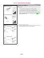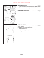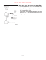
1
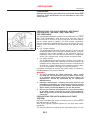
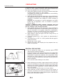
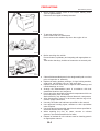
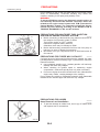
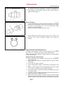
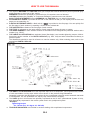
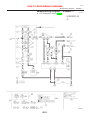
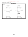
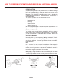
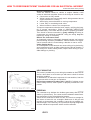
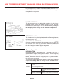
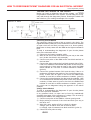
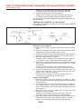
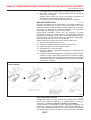
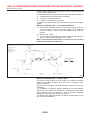
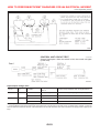
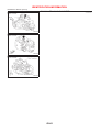
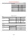
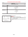
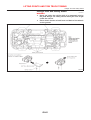
GENERAL INFORMATION
SECTION
GI
CONTENTS
PRECAUTIONS ...............................................................3
Precautions ..................................................................3
PRECAUTIONS FOR SUPPLEMENTAL
RESTRAINT SYSTEM (SRS) ″AIR BAG″ AND
″SEAT BELT PRE-TENSIONER″ .................................3
PRECAUTIONS FOR NATS (NISSAN ANTI-THEFT
SYSTEM) ..................................................................3
GENERAL PRECAUTIONS .........................................4
PRECAUTIONS FOR MULTIPORT FUEL
INJECTION SYSTEM OR ENGINE CONTROL
SYSTEM ...................................................................6
PRECAUTIONS FOR THREE WAY CATALYST ...........6
PRECAUTIONS FOR HOSES .....................................6
PRECAUTIONS FOR ENGINE OILS ...........................7
PRECAUTIONS FOR FUEL ........................................8
PRECAUTIONS FOR AIR CONDITIONING ..................8
HOW TO USE THIS MANUAL........................................9
HOW TO READ WIRING DIAGRAMS..........................11
Sample/Wiring Diagram - EXAMPL - ........................11
OPTIONAL SPLICE..................................................12
Description .................................................................13
CONNECTOR SYMBOLS .........................................15
HARNESS INDICATION ...........................................16
COMPONENT INDICATION ......................................16
SWITCH POSITIONS ...............................................16
DETECTABLE LINES AND NON-DETECTABLE
LINES .....................................................................17
MULTIPLE SWITCH .................................................18
REFERENCE AREA .................................................19
HOW TO PERFORM EFFICIENT DIAGNOSES
FOR AN ELECTRICAL INCIDENT ...............................21
Work Flow..................................................................21
Incident Simulation Tests...........................................22
INTRODUCTION ......................................................22
VEHICLE VIBRATION ..............................................22
HEAT SENSITIVE ....................................................23
FREEZING ..............................................................23
WATER INTRUSION ................................................24
ELECTRICAL LOAD .................................................24
COLD OR HOT START UP.......................................24
Circuit Inspection .......................................................24
INTRODUCTION ......................................................24
TESTING FOR ″OPENS″ IN THE CIRCUIT ................25
TESTING FOR ″SHORTS″ IN THE CIRCUIT ..............26
GROUND INSPECTION ...........................................27
VOLTAGE DROP TESTS ..........................................27
CONTROL UNIT CIRCUIT TEST ...............................29
HOW TO FOLLOW TROUBLE DIAGNOSES...............31
How to Follow Test Groups in Trouble Diagnoses....32
Key to Symbols Signifying Measurements or
Procedures.................................................................33
CONSULT-II CHECKING SYSTEM ...............................35
Function and System Application ..............................35
Nickel Metal Hydride Battery Replacement...............36
Checking Equipment..................................................36
CONSULT-II Data Link Connector (DLC) Circuit ......37
INSPECTION PROCEDURE .....................................37
IDENTIFICATION INFORMATION ................................38
Model Variation ..........................................................38
PREFIX AND SUFFIX DESIGNATIONS .....................39
Identification Number.................................................39
VEHICLE IDENTIFICATION NUMBER
ARRANGEMENT .....................................................40
IDENTIFICATION PLATE..........................................40
ENGINE SERIAL NUMBER.......................................41
AUTOMATIC TRANSAXLE NUMBER ........................41
MANUAL TRANSAXLE NUMBER ..............................42
Dimensions ................................................................43
Wheels and Tires.......................................................43
LIFTING POINTS AND TOW TRUCK TOWING ...........44
Preparation ................................................................44
SPECIAL SERVICE TOOLS ......................................44
Board-on Lift ..............................................................44
Garage Jack and Safety Stand .................................45
2-pole Lift ...................................................................46
Tow Truck Towing ......................................................47
TOWING AN AUTOMATIC TRANSAXLE MODEL
WITH FOUR WHEELS ON GROUND ........................47
TOWING AN AUTOMATIC TRANSAXLE MODEL
WITH REAR WHEELS RAISED (WITH FRONT
WHEELS ON GROUND) ..........................................47
CONTENTS
TOWING POINT .......................................................48
TIGHTENING TORQUE OF STANDARD BOLTS ........49
ISO 15031-2 TERMINOLOGY LIST ..............................50
GI-2
(Cont’d)
ISO 15031-2 Terminology List ...................................50
PRECAUTIONS
Precautions
Precautions
NJGI0001
Observe the following precautions to ensure safe and proper
servicing. These precautions are not described in each individual section.
PRECAUTIONS FOR SUPPLEMENTAL RESTRAINT
SYSTEM (SRS) “AIR BAG” AND “SEAT BELT
PRE-TENSIONER”
NJGI0001S01
SGI646
The Supplemental Restraint System such as “AIR BAG” and “SEAT
BELT PRE-TENSIONER” used along with a seat belt, helps to
reduce the risk or severity of injury to the driver and front passenger for certain types of collision. The SRS system composition
which is available to NISSAN MODEL N16 is as follows (The composition varies according to the destination and optional equipment.):
+ For a frontal collision
The Supplemental Restraint System consists of driver air bag
module (located in the center of the steering wheel), front passenger air bag module (located on the instrument panel on
passenger side), front seat belt pre-tensioners, a diagnoses
sensor unit, warning lamp, wiring harness and spiral cable.
+ For a side collision
The Supplemental Restraint System consists of front side air
bag module (located in the outer side of front seat), side air bag
(satellite) sensor, diagnoses sensor unit (one of components of
air bags for a frontal collision), wiring harness, warning lamp
(one of components of air bags for a frontal collision).
Information necessary to service the system safely is included in
the RS section of this Service Manual.
WARNING:
+ To avoid rendering the SRS inoperative, which could
increase the risk of personal injury or death in the event
of a collision which would result in air bag inflation, all
maintenance should be performed by an authorized
NISSAN dealer.
+ Improper maintenance, including incorrect removal and
installation of the SRS, can lead to personal injury caused
by unintentional activation of the system. For removal of
Spiral Cable and Air Bag Module, see the RS section.
+ Do not use electrical test equipment on any circuit related
to the SRS unless instructed to in this Service Manual.
SRS wiring harnesses can be identified by yellow harness
connector.
PRECAUTIONS FOR NATS (NISSAN ANTI-THEFT
SYSTEM)
NJGI0001S02
NATS will immobilize the engine if someone tries to start it without
the registered key of NATS.
Both of the originally supplied ignition key IDs have been NATS
registered.
The security indicator is located on the instrument panel or in the
GI-3
PRECAUTIONS
Precautions (Cont’d)
combination meter. The indicator blinks when the ignition switch is
in “OFF” or “ACC” position. Therefore, NATS warns outsiders that
the vehicle is equipped with the anti-theft system.
+ When NATS detects trouble, the security indicator lamp lights
up while ignition switch is in “ON” position.
This lighting up indicates that the anti-theft is not functioning,
so prompt service is required.
+ When servicing NATS (trouble diagnoses, system initialization
and additional registration of other NATS ignition key IDs),
CONSULT-II hardware and CONSULT-II NATS software is
necessary.
Regarding the procedures of NATS initialization and NATS
ignition key ID registration, refer to CONSULT-II operation
manual, NATS.
Therefore, CONSULT-II NATS software (program card and
operation manual) must be kept strictly confidential to maintain the integrity of the anti-theft function.
+ When servicing NATS (trouble diagnoses, system initialization
and additional registration of other NATS ignition key IDs), it
may be necessary to re-register original key identification.
Therefore, be sure to receive all keys from vehicle owner. A
maximum of five key IDs can be registered into NATS.
+ When failing to start the engine first time using the key of
NATS, start as follows.
a) Leave the ignition key in “ON” position for approximately 5
seconds.
b) Turn ignition key to “OFF” or “LOCK” position and wait approximately 5 seconds.
c) Repeat step 1 and 2 again.
d) Restart the engine while keeping the key separate from any
others on key-chain.
GENERAL PRECAUTIONS
NJGI0001S03
+
Do not operate the engine for an extended period of time
without proper exhaust ventilation.
Keep the work area well ventilated and free of any inflammable
materials. Special care should be taken when handling any
inflammable or poisonous materials, such as gasoline, refrigerant gas, etc. When working in a pit or other enclosed area,
be sure to properly ventilate the area before working with hazardous materials.
Do not smoke while working on the vehicle.
+
Before jacking up the vehicle, apply wheel chocks or other tire
blocks to the wheels to prevent the vehicle from moving. After
jacking up the vehicle, support the vehicle weight with safety
stands at the points designated for proper lifting before working on the vehicle.
These operations should be done on a level surface.
When removing a heavy component such as the engine or
transaxle, be careful not to lose your balance and drop them.
Also, do not allow them to strike adjacent parts, especially the
brake tubes and master cylinder.
SGI285
+
SGI231
GI-4
PRECAUTIONS
Precautions (Cont’d)
+
Before starting repairs which do not require battery power:
Turn off ignition switch.
Disconnect the negative battery terminal.
+
To prevent serious burns:
Avoid contact with hot metal parts.
Do not remove the radiator cap when the engine is hot.
+
Before servicing the vehicle:
Protect fenders, upholstery and carpeting with appropriate covers.
Take caution that keys, buckles or buttons do not scratch paint.
+
Clean all disassembled parts in the designated liquid or solvent
prior to inspection or assembly.
Replace oil seals, gaskets, packings, O-rings, locking washers,
cotter pins, self-locking nuts, etc. with new ones.
Replace inner and outer races of tapered roller bearings and
needle bearings as a set.
Arrange the disassembled parts in accordance with their
assembled locations and sequence.
Do not touch the terminals of electrical components which use
microcomputers (such as ECMs).
Static electricity may damage internal electronic components.
After disconnecting vacuum or air hoses, attach a tag to indicate the proper connection.
Use only the fluids and lubricants specified in this manual.
Use approved bonding agent, sealants or their equivalents
when required.
Use tools and recommended special tools where specified for
safe and efficient service repairs.
When repairing the fuel, oil, water, vacuum or exhaust
systems, check all affected lines for leaks.
Dispose of drained oil or the solvent used for cleaning parts in
an appropriate manner.
SEF289H
SGI233
SGI234
+
+
+
+
+
+
+
+
+
+
GI-5
PRECAUTIONS
Precautions (Cont’d)
Do not attempt to top off the fuel tank after the fuel pump nozzle
shuts off automatically. Continued refueling may cause fuel
overflow, resulting in fuel spray and possibly a fire.
WARNING:
To prevent ECM from storing the diagnostic trouble codes, do
not carelessly disconnect the harness connectors which are
related to the engine control system and TCM (Transmission
Control Module) system. The connectors should be disconnected only when working according to the WORK FLOW of
TROUBLE DIAGNOSES in EC and AT sections.
PRECAUTIONS FOR MULTIPORT FUEL INJECTION
SYSTEM OR ENGINE CONTROL SYSTEM
NJGI0001S04
+
+
+
SGI787
Before connecting or disconnecting any harness connector for
the multiport fuel injection system or ECM:
Turn ignition switch to “OFF” position.
Disconnect negative battery terminal.
Otherwise, there may be damage to ECM.
Before disconnecting pressurized fuel line from fuel pump to
injectors, be sure to release fuel pressure.
Be careful not to jar components such as ECM and mass air
flow sensor.
PRECAUTIONS FOR THREE WAY CATALYST
NJGI0001S05
If a large amount of unburned fuel flows into the catalyst, the catalyst temperature will be excessively high. To prevent this, follow the
instructions below:
+ Use unleaded gasoline only. Leaded gasoline will seriously
damage the three way catalyst.
+ When checking for ignition spark or measuring engine
compression, make tests quickly and only when necessary.
+ Do not run engine when the fuel tank level is low, otherwise the
engine may misfire, causing damage to the catalyst.
Do not place the vehicle on flammable material. Keep flammable
material off the exhaust pipe and the three way catalyst.
PRECAUTIONS FOR HOSES
Hose Removal and Installation
+
NJGI0001S06
NJGI0001S0601
To prevent damage to rubber hose, do not pry off rubber hose
with tapered tool or screwdriver.
SMA019D
GI-6
PRECAUTIONS
Precautions (Cont’d)
+
To reinstall the rubber hose securely, make sure of hose insertion length and clamp orientation. (If tube is equipped with
hose stopper, insert rubber hose into tube until it butts up
against hose stopper.)
SMA020D
Hose Clamping
+
+
NJGI0001S0602
If old rubber hose is re-used, install hose clamp in its original
position (at the indentation where the old clamp was). If there
is a trace of tube bulging left on the old rubber hose, align
rubber hose at that position.
Discard old clamps; replace with new ones.
SMA021D
+
After installing leaf spring clamps, apply force to them in the
direction of the arrow, tightening rubber hose equally all
around.
SMA022D
PRECAUTIONS FOR ENGINE OILS
NJGI0001S07
Prolonged and repeated contact with used engine oil may cause
skin cancer. Try to avoid direct skin contact with used oil.
If skin contact is made, wash thoroughly with soap or hand cleaner
as soon as possible.
Health Protection Precautions
+
+
+
+
+
+
+
+
NJGI0001S0701
Avoid prolonged and repeated contact with oils, particularly
used engine oils.
Wear protective clothing, including impervious gloves where
practicable.
Do not put oily rags in pockets.
Avoid contaminating clothes, particularly underclothing, with
oil.
Heavily soiled clothing and oil-impregnated footwear should
not be worn. Overalls must be cleaned regularly.
First Aid treatment should be obtained immediately for open
cuts and wounds.
Use barrier creams, applying them before each work period, to
help the removal of oil from the skin.
Wash with soap and water to ensure all oil is removed (skin
cleansers and nail brushes will help). Preparations containing
lanolin replace the natural skin oils which have been removed.
GI-7
PRECAUTIONS
Precautions (Cont’d)
+
+
+
+
Do not use gasoline, kerosine, diesel fuel, gas oil, thinners or
solvents for cleaning skin.
If skin disorders develop, obtain medical advice without delay.
Where practicable, degrease components prior to handling.
Where there is a risk of eye contact, eye protection should be
worn, for example, chemical goggles or face shields; in addition an eye wash facility should be provided.
Environmental Protection Precautions
NJGI0001S0702
Burning used engine oil in small space heaters or boilers can be
recommended only for units of approved design. The heating system must meet the requirements of HM Inspectorate of Pollution for
small burners of less than 0.4 MW. If in doubt, check with the
appropriate local authority and/or manufacturer of the approved
appliance.
Dispose of used oil and used oil filters through authorized waste
disposal contractors to licensed waste disposal sites, or to the
waste oil reclamation trade. If in doubt, contact the local authority
for advice on disposal facilities.
It is illegal to pour used oil on to the ground, down sewers or drains,
or into water courses.
The regulations concerning the pollution vary between
regions.
PRECAUTIONS FOR FUEL
Gasoline Engine
NJGI0001S08
NJGI0001S0803
Models with three way catalyst
Unleaded premium gasoline of at least 95 octane (RON)
If premium gasoline is not available, unleaded regular gasoline with an octane rating of 91 (RON) may be temporarily
used, but only under the following precautions:
+ Have the fuel tank filled only partially with unleaded regular gasoline, and fill up with premium unleaded gasoline
as soon as possible.
+ Avoid full throttle driving and abrupt acceleration.
CAUTION:
Do not use leaded gasoline. Using leaded gasoline will damage the three way catalyst.
Diesel Engine*:
NJGI0001S0804
Diesel fuel of at least 50 cetane
* If two types of diesel fuel are available, use summer or winter
fuel properly according to the following temperature conditions.
+ Above −7°C (20°F) ... Summer type diesel fuel.
+ Below −7°C (20°F) ... Winter type diesel fuel.
CAUTION:
+ Do not use home heating oil, gasoline, or other alternate
fuels in your diesel engine. The use of those can cause
engine damage.
+ Do not use summer fuel at temperatures below −7°C
(20°F). The cold temperatures will cause wax to form in the
fuel. As a result, it may prevent the engine from running
smoothly.
+ Do not add gasoline or other alternate fuels to diesel fuel.
PRECAUTIONS FOR AIR CONDITIONING
NJGI0001S09
Use an approved refrigerant recovery unit any time the air conditioning system must be discharged. Refer to HA-78, “HFC-134a
(R-134a) Service Procedure” for specific instructions.
GI-8
NJGI0002
HOW TO USE THIS MANUAL
+
+
+
+
+
+
+
The captions WARNING and CAUTION warm you of steps that must be followed to prevent personal injury
and/or damage to some part of the vehicle.
WARNING indicates the possibility of personal injury if instructions are not followed.
CAUTION indicates the possibility of component damage if instructions are not followed.
BOLD TYPED STATEMENTS except WARNING and CAUTION give you helpful information.
ALPHABETICAL INDEX is provided at the end of this manual so that you can rapidly find the item and
page you are searching for.
A QUICK REFERENCE INDEX, a black tab (e.g.
) is provided on the first page. You can quickly find
the first page of each section by matching it to the section’s black tab.
THE CONTENTS are listed on the first page of each section.
THE TITLE is indicated on the upper portion of each page and shows the part or system.
THE PAGE NUMBER of each section consists of two letters which designate the particular section and a
number (e.g. “BR-5”).
THE LARGE ILLUSTRATIONS are exploded views (See below.) and contain tightening torques, lubrication points, section number of the PARTS CATALOG (e.g. SEC. 440) and other information necessary to
perform repairs.
The illustrations should be used in reference to service matters only. When ordering parts, refer to the
appropriate PARTS CATALOG.
SBR364AC
+
+
+
THE SMALL ILLUSTRATIONS show the important steps such as inspection, use of special tools, knacks
of work and hidden or tricky steps which are not shown in the previous large illustrations.
Assembly, inspection and adjustment procedures for the complicated units such as the automatic transaxle
or transmission, etc. are presented in a step-by-step format where necessary.
The UNITS given in this manual are primarily expressed as the SI UNIT (International System of Unit),
and alternatively expressed in the metric system and in the yard/pound system.
“Example”
Tightening torque:
59 - 78 N·m (6.0 - 8.0 kg-m, 43 - 58 ft-lb)
TROUBLE DIAGNOSES are included in sections dealing with complicated components.
GI-9
HOW TO USE THIS MANUAL
+
+
SERVICE DATA AND SPECIFICATIONS are contained at the end of each section for quick reference of
data.
The following SYMBOLS AND ABBREVIATIONS are used:
SYMBOL
ABBREVIATION
SYMBOL
Tightening torque
ABBREVIATION
2-Wheel Drive
2WD
Should be lubricated with grease. Unless otherwise indicated, use recommended multi-purpose grease.
A/C
Should be lubricated with oil.
P/S
Power Steering
Sealing point
SST
Special Service Tools
Checking point
SAE
Society of Automotive Engineers, Inc.
Always replace after every disassembly.
ATF
Automatic Transmission Fluid
Apply petroleum jelly.
Air Conditioner
D1
j
P
Drive range 1st gear
Apply ATF.
D2
Drive range 2nd gear
★
Select with proper thickness.
D3
Drive range 3rd gear
✩
Adjustment is required.
D4
Drive range 4th gear
Service Data and Specifications
OD
Overdrive
LH, RH
Left-Hand, Right-Hand
22
2nd range 2nd gear
FR, RR
Front, Rear
21
2nd range 1st gear
M/T
Manual Transaxle/Transmission
12
1st range 2nd gear
A/T
Automatic Transaxle/Transmission
11
1st range 1st gear
SDS
GI-10
NJGI0003
HOW TO READ WIRING DIAGRAMS
Sample/Wiring Diagram — EXAMPL —
Sample/Wiring Diagram — EXAMPL —
+
NJGI0003S01
For Description, refer to GI-13.
SGI091A
GI-11
HOW TO READ WIRING DIAGRAMS
Sample/Wiring Diagram — EXAMPL — (Cont’d)
OPTIONAL SPLICE
NJGI0003S0101
SGI942
GI-12
HOW TO READ WIRING DIAGRAMS
Description
Description
Number
Item
=NJGI0003S02
Description
1
Power condition
+ This shows the condition when the system receives battery positive voltage (can be
operated).
2
Fusible link
+ The double line shows that this is a fusible link.
+ The open circle shows current flow in, and the shaded circle shows current flow out.
3
Fusible link/fuse location
+ This shows the location of the fusible link or fuse in the fusible link or fuse box. For
arrangement, refer to EL-11, “POWER SUPPLY ROUTING”.
4
Fuse
+ The single line shows that this is a fuse.
+ The open circle shows current flow in, and the shaded circle shows current flow out.
5
Current rating
+ This shows the current rating of the fusible link or fuse.
6
Connectors
+ This shows that connector E3 is female and connector M1 is male.
+ The G/R wire is located in the 1A terminal of both connectors.
+ Terminal number with an alphabet (1A, 5B, etc.) indicates that the connector is SMJ connector. Refer to GI-19.
7
Optional splice
+ The open circle shows that the splice is optional depending on vehicle application.
8
Splice
+ The shaded circle shows that the splice is always on the vehicle.
9
Page crossing
+ This arrow shows that the circuit continues to an adjacent page.
+ The A will match with the A on the preceding or next page.
10
Common connector
+ The dotted lines between terminals show that these terminals are part of the same connector.
11
Option abbreviation
+ This shows that the circuit is optional depending on vehicle application.
12
Relay
+ This shows an internal representation of the relay. For details, refer to EL-8, “STANDARDIZED RELAY”.
13
Connectors
+ This shows that the connector is connected to the body or a terminal with bolt or nut.
+ This shows a code for the color of the wire.
14
Wire color
B = Black
W = White
R = Red
G = Green
L = Blue
Y = Yellow
LG = Light Green
BR = Brown
OR = Orange
P = Pink
PU = Purple
GY = Gray
SB = Sky Blue
CH = Dark Brown
DG = Dark Green
When the wire color is striped, the base color is given first, followed by the stripe color as
shown below:
Example: L/W = Blue with White Stripe
15
Option description
+ This shows a description of the option abbreviation used on the page.
16
Switch
+ This shows that continuity exists between terminals 1 and 2 when the switch is in the A
position. Continuity exists between terminals 1 and 3 when the switch is in the B position.
17
Assembly parts
+ Connector terminal in component shows that it is a harness incorporated assembly.
18
Cell code
+ This identifies each page of the wiring diagram by section, system and wiring diagram
page number.
Current flow arrow
+ Arrow indicates electric current flow, especially where the direction of standard flow (vertically downward or horizontally from left to right) is difficult to follow.
+ A double arrow “
” shows that current can flow in either direction depending on circuit operation.
19
GI-13
HOW TO READ WIRING DIAGRAMS
Description (Cont’d)
Number
Item
Description
20
System branch
+ This shows that the system branches to another system identified by cell code (section
and system).
21
Page crossing
+ This arrow shows that the circuit continues to another page identified by cell code.
+ The C will match with the C on another page within the system other than the next or
preceding pages.
22
Shielded line
+ The line enclosed by broken line circle shows shield wire.
23
Component box in
wave line
+ This shows that another part of the component is also shown on another page (indicated
by wave line) within the system.
24
Component name
+ This shows the name of a component.
25
Connector number
+ This shows the connector number.
+ The letter shows which harness the connector is located in.
Example: M: main harness. For detail and to locate the connector, refer to EL-528, “Main
Harness”. A coordinate grid is included for complex harnesses to aid in locating connectors.
26
Ground (GND)
+ The line spliced and grounded under wire color shows that ground line is spliced at the
grounded connector.
27
Ground (GND)
+ This shows the ground connection. For detailed ground distribution information, refer to
EL-39, “GROUND DISTRIBUTION”.
28
Connector views
+ This area shows the connector faces of the components in the wiring diagram on the
page.
29
Common component
+ Connectors enclosed in broken line show that these connectors belong to the same
component.
30
Connector color
+ This shows a code for the color of the connector. For code meaning, refer to wire color
codes, Number 14 of this chart.
31
Fusible link and fuse
box
+ This shows the arrangement of fusible link(s) and fuse(s), used for connector views of
“POWER SUPPLY ROUTING” in EL section.
The open square shows current flow in, and the shaded square shows current flow out.
32
Reference area
+ This shows that more information on the Super Multiple Junction (SMJ), Electrical Units,
exists at the end of the manual. Refer to GI-19 for details.
GI-14
HOW TO READ WIRING DIAGRAMS
Description (Cont’d)
CONNECTOR SYMBOLS
=NJGI0003S0201
Most of connector symbols in wiring diagrams are shown from the
terminal side.
+ Connector symbols shown from the terminal side are enclosed
by a single line and followed by the direction mark.
+ Connector symbols shown from the harness side are enclosed
by a double line and followed by the direction mark.
+ Certain systems and components, especially those related to
OBD, may use a new style slide-locking type harness connector. For description and how to disconnect, refer to EL-6, “HARNESS CONNECTOR”.
SGI364
+
Male and female terminals
Connector guides for male terminals are shown in black and
female terminals in white in wiring diagrams.
SGI363
GI-15
HOW TO READ WIRING DIAGRAMS
Description (Cont’d)
HARNESS INDICATION
+
+
COMPONENT INDICATION
+
NJGI0003S0202
Letter designations next to test meter probe indicate harness
(connector) wire color.
Connector numbers in a single circle M33 indicate harness
connectors.
NJGI0003S0203
Connector numbers in a double circle F211 indicate component connectors.
AGI070
SWITCH POSITIONS
NJGI0003S0204
Switches are shown in wiring diagrams as if the vehicle is in the
“normal” condition.
A vehicle is in the “normal” condition when:
+ ignition switch is “OFF”,
+ doors, hood and trunk lid/back door are closed,
+ pedals are not depressed, and
+ parking brake is released.
SGI860
GI-16
HOW TO READ WIRING DIAGRAMS
Description (Cont’d)
DETECTABLE LINES AND NON-DETECTABLE LINES
=NJGI0003S0205
In some wiring diagrams, two kinds of lines, representing wires,
with different weight are used.
+ A line with regular weight (wider line) represents a “detectable
line for DTC (Diagnostic Trouble Code)”. A “detectable line for
DTC” is a circuit in which ECM can detect its malfunctions with
the on board diagnostic system.
+ A line with less weight (thinner line) represents a “non-detectable line for DTC”. A “non-detectable line for DTC” is a circuit
in which ECM cannot detect its malfunctions with the on board
diagnostic system.
SGI862-A
GI-17
HOW TO READ WIRING DIAGRAMS
Description (Cont’d)
MULTIPLE SWITCH
=NJGI0003S0206
The continuity of multiple switch is described in two ways as shown
below.
+ The switch chart is used in schematic diagrams.
+ The switch diagram is used in wiring diagrams.
SGI875
GI-18
HOW TO READ WIRING DIAGRAMS
Description (Cont’d)
REFERENCE AREA
=NJGI0003S0207
The Reference Area of the wiring diagram contains references to
additional electrical reference pages at the end of the manual. If
connector numbers and titles are shown in the Reference Area of
the wiring diagram, these connector symbols are not shown in the
Connector Area.
SGI092A
Super multiple junction (SMJ)
In a wiring diagram, the SMJ connectors include a letter of the
alphabet in the terminal number.
SMJ connector numbers are shown in the Reference Area of the
wiring diagram. SMJ terminal arrangement can be found on the
electrical reference pages at the end of the manual. For terminal
arrangement of these connectors, refer to the “SUPER MULTIPLE
JUNCTION (SMJ)” electrical reference page at the end of the
GI-19
HOW TO READ WIRING DIAGRAMS
Description (Cont’d)
manual.
Fuse block — Junction box (J/B)
Fuse block — Junction box (J/B) connector number is shown in the
Reference Area of the wiring diagram. For connector terminal and
fuse arrangement, refer to the “FUSE BLOCK — Junction Box
(J/B)” electrical reference page at the end of the manual.
Fuse and fusible link box
For fuse arrangement in the fuse and fusible link box, refer to the
“FUSE AND FUSIBLE LINK BOX” electrical reference page at the
end of the manual.
Electrical units
Electrical unit connector symbols are shown in the Connector Area
of the wiring diagram.
However, when there is not enough space to show the connector
terminal arrangement in the Connector Area of the wiring diagram,
the electrical unit connector number is shown in the Reference
Area of the wiring diagram. For electrical unit connector terminal
arrangement, refer to the “ELECTRICAL UNITS” electrical reference page at the end of the manual. Most of the electrical unit
connectors on this page are shown from the harness side of the
connector.
Joint connector
Joint connector symbols are shown in the connector area of the
wiring diagram. For connector internal wiring layout and joint connector terminal arrangement, refer to the “JOINT CONNECTOR
(J/C)” electrical reference page at the end of the manual.
GI-20
NJGI0005
HOW TO PERFORM EFFICIENT DIAGNOSES FOR AN ELECTRICAL INCIDENT
Work Flow
Work Flow
NJGI0005S01
SGI838
STEP
STEP 1
DESCRIPTION
Get detailed information about the conditions and the environment when the incident occurred.
The following are key pieces of information required to make a good analysis:
WHAT
Vehicle Model, Engine, Transmission and the System (i.e. Radio).
WHEN
Date, Time of Day, Weather Conditions, Frequency.
WHERE
Road Conditions, Altitude and Traffic Situation.
HOW
System Symptoms, Operating Conditions (Other Components Interaction).
Service History and if any After Market Accessories have been installed.
STEP 2
Operate the system, road test if necessary.
Verify the parameter of the incident.
If the problem can not be duplicated, refer to “Incident Simulation Tests” next page.
STEP 3
Get the proper diagnoses materials together including:
POWER SUPPLY ROUTING
System Operation Descriptions
Applicable Service Manual Sections
Check for any Service Bulletin.
Identify where to begin diagnoses based upon your knowledge of the system operation and the customer comments.
STEP 4
Inspect the system for mechanical binding, loose connectors or wiring damage.
Determine which circuits and components are involved and diagnose using the Power Supply Routing
and Harness Layouts.
STEP 5
Repair or replace the incident circuit or component.
STEP 6
Operate the system in all modes. Verify the system works properly under all conditions. Make sure you
have not inadvertently created a new incident during your diagnoses or repair steps.
GI-21
HOW TO PERFORM EFFICIENT DIAGNOSES FOR AN ELECTRICAL INCIDENT
Incident Simulation Tests
Incident Simulation Tests
INTRODUCTION
NJGI0005S02
NJGI0005S0201
Sometimes the symptom is not present when the vehicle is brought
in for service. If possible, re-create the conditions present at the
time of the incident. Doing so may help avoid a No Trouble Found
Diagnoses. The following section illustrates ways to simulate the
conditions/environment under which the owner experiences an
electrical incident.
The section is broken into the six following topics:
+ Vehicle vibration
+ Heat sensitive
+ Freezing
+ Water intrusion
+ Electrical load
+ Cold or hot start up
Get a thorough description of the incident from the customer. It is
important for simulating the conditions of the problem.
VEHICLE VIBRATION
NJGI0005S0202
The problem may occur or become worse while driving on a rough
road or when engine is vibrating (idle with A/C on). In such a case,
you will want to check for a vibration related condition. Refer to the
illustration below.
Connectors & Harness
Determine which connectors and wiring harness would affect the
electrical system you are inspecting. Gently shake each connector and harness while monitoring the system for the incident you
are trying to duplicate. This test may indicate a loose or poor electrical connection.
Hint
Connectors can be exposed to moisture. It is possible to get a thin
film of corrosion on the connector terminals. A visual inspection
may not reveal this without disconnecting the connector. If the
problem occurs intermittently, perhaps the problem is caused by
corrosion. It is a good idea to disconnect, inspect and clean the
terminals on related connectors in the system.
Sensors & Relays
Gently apply a slight vibration to sensors and relays in the system
you are inspecting.
This test may indicate a loose or poorly mounted sensor or relay.
SGI839
GI-22
HOW TO PERFORM EFFICIENT DIAGNOSES FOR AN ELECTRICAL INCIDENT
Incident Simulation Tests (Cont’d)
Engine Compartment
There are several reasons a vehicle or engine vibration could
cause an electrical complaint. Some of the things to check for are:
+ Connectors not fully seated.
+ Wiring harness not long enough and is being stressed due to
engine vibrations or rocking.
+ Wires laying across brackets or moving components.
+ Loose, dirty or corroded ground wires.
+ Wires routed too close to hot components.
To inspect components under the hood, start by verifying the integrity of ground connections. (Refer to GROUND INSPECTION
described later.) First check that the system is properly grounded.
Then check for loose connection by gently shaking the wiring or
components as previously explained. Using the wiring diagrams
inspect the wiring for continuity.
Behind The Instrument Panel
An improperly routed or improperly clamped harness can become
pinched during accessory installation. Vehicle vibration can aggravate a harness which is routed along a bracket or near a screw.
Under Seating Areas
An unclamped or loose harness can cause wiring to be pinched by
seat components (such as slide guides) during vehicle vibration. If
the wiring runs under seating areas, inspect wire routing for possible damage or pinching.
HEAT SENSITIVE
NJGI0005S0203
The owner’s problem may occur during hot weather or after car has
sat for a short time. In such cases you will want to check for a heat
sensitive condition.
To determine if an electrical component is heat sensitive, heat the
component with a heat gun or equivalent.
Do not heat components above 60°C (140°F). If incident occurs
while heating the unit, either replace or properly insulate the component.
SGI842
FREEZING
NJGI0005S0204
The customer may indicate the incident goes away after the car
warms up (winter time). The cause could be related to water freezing somewhere in the wiring/electrical system.
There are two methods to check for this. The first is to arrange for
the owner to leave his car overnight. Make sure it will get cold
enough to demonstrate his complaint. Leave the car parked outside overnight. In the morning, do a quick and thorough diagnoses
of those electrical components which could be affected.
SGI843
GI-23
HOW TO PERFORM EFFICIENT DIAGNOSES FOR AN ELECTRICAL INCIDENT
Incident Simulation Tests (Cont’d)
The second method is to put the suspect component into a freezer
long enough for any water to freeze. Reinstall the part into the car
and check for the reoccurrence of the incident. If it occurs, repair
or replace the component.
WATER INTRUSION
NJGI0005S0205
The incident may occur only during high humidity or in rainy/snowy
weather. In such cases the incident could be caused by water
intrusion on an electrical part. This can be simulated by soaking the
car or running it through a car wash.
Do not spray water directly on any electrical components.
SGI844
ELECTRICAL LOAD
NJGI0005S0206
The incident may be electrical load sensitive. Perform diagnoses
with all accessories (including A/C, rear window defogger, radio,
fog lamps) turned on.
COLD OR HOT START UP
NJGI0005S0207
On some occasions an electrical incident may occur only when the
car is started cold. Or it may occur when the car is restarted hot
shortly after being turned off. In these cases you may have to keep
the car overnight to make a proper diagnoses.
SGI845
Circuit Inspection
NJGI0005S03
INTRODUCTION
NJGI0005S0301
In general, testing electrical circuits is an easy task if it is
approached in a logical and organized method. Before beginning
it is important to have all available information on the system to be
tested. Also, get a thorough understanding of system operation.
Then you will be able to use the appropriate equipment and follow
the correct test procedure.
You may have to simulate vehicle vibrations while testing electrical
components. Gently shake the wiring harness or electrical component to do this.
OPEN
A circuit is open when there is no continuity through a section of
the circuit.
SHORT
There are two types of shorts.
+ SHORT CIRCUIT
When a circuit contacts another circuit
and causes the normal resistance to
change.
+ SHORT TO GROUND When a circuit contacts a ground source
and grounds the circuit.
GI-24
HOW TO PERFORM EFFICIENT DIAGNOSES FOR AN ELECTRICAL INCIDENT
Circuit Inspection (Cont’d)
TESTING FOR “OPENS” IN THE CIRCUIT
NJGI0005S0302
Before you begin to diagnose and test the system, you should
rough sketch a schematic of the system. This will help you to logically walk through the diagnoses process. Drawing the sketch will
also reinforce your working knowledge of the system.
SGI846
Continuity Check Method
The continuity check is used to find an open in the circuit. The
Digital Multimeter (DMM) set on the resistance function will indicate
an open circuit as over limit (no beep tone or no ohms symbol).
Make sure to always start with the DMM at the highest resistance
level.
To help in understanding the diagnoses of open circuits please
refer to the schematic above.
1) Disconnect the battery negative cable.
2) Start at one end of the circuit and work your way to the other
end. (At the fuse block in this example)
3) Connect one probe of the DMM to the fuse block terminal on
the load side.
4) Connect the other probe to the fuse block (power) side of SW1.
Little or no resistance will indicate that portion of the circuit has
good continuity. If there were an open in the circuit, the DMM
would indicate an over limit or infinite resistance condition.
(point A)
5) Connect the probes between SW1 and the relay. Little or no
resistance will indicate that portion of the circuit has good continuity. If there were an open in the circuit, the DMM would
indicate an over limit or infinite resistance condition. (point B)
6) Connect the probes between the relay and the solenoid. Little
or no resistance will indicate that portion of the circuit has good
continuity. If there were an open in the circuit, the DMM would
indicate an over limit or infinite resistance condition. (point C)
Any circuit can be diagnosed using the approach in the above
example.
Voltage Check Method
To help in understanding the diagnoses of open circuits please
refer to the previous schematic.
In any powered circuit, an open can be found by methodically
checking the system for the presence of voltage. This is done by
switching the DMM to the voltage function.
1) Connect one probe of the DMM to a known good ground.
2) Begin probing at one end of the circuit and work your way to
the other end.
3) With SW1 open, probe at SW1 to check for voltage.
voltage; open is further down the circuit than SW1.
no voltage; open is between fuse block and SW1 (point A).
4) Close SW1 and probe at relay.
GI-25
HOW TO PERFORM EFFICIENT DIAGNOSES FOR AN ELECTRICAL INCIDENT
Circuit Inspection (Cont’d)
voltage; open is further down the circuit than the relay.
no voltage; open is between SW1 and relay (point B).
5) Close the relay and probe at the solenoid.
voltage; open is further down the circuit than the solenoid.
no voltage; open is between relay and solenoid (point C).
Any powered circuit can be diagnosed using the approach in the
above example.
TESTING FOR “SHORTS” IN THE CIRCUIT
NJGI0005S0303
To simplify the discussion of shorts in the system please refer to
the schematic below.
SGI847
Resistance Check Method
1) Disconnect the battery negative cable and remove the blown
fuse.
2) Disconnect all loads (SW1 open, relay disconnected and solenoid disconnected) powered through the fuse.
3) Connect one probe of the ohmmeter to the load side of the fuse
terminal. Connect the other probe to a known good ground.
4) With SW1 open, check for continuity.
continuity; short is between fuse terminal and SW1 (point A).
no continuity; short is further down the circuit than SW1.
5) Close SW1 and disconnect the relay. Put probes at the load
side of fuse terminal and a known good ground. Then, check
for continuity.
continuity; short is between SW1 and the relay (point B).
no continuity; short is further down the circuit than the relay.
6) Close SW1 and jump the relay contacts with jumper wire. Put
probes at the load side of fuse terminal and a known good
ground. Then, check for continuity.
continuity; short is between relay and solenoid (point C).
no continuity; check solenoid, retrace steps.
Voltage Check Method
1) Remove the blown fuse and disconnect all loads (i.e. SW1
open, relay disconnected and solenoid disconnected) powered
through the fuse.
2) Turn the ignition key to the ON or START position. Verify battery voltage at the B + side of the fuse terminal (one lead on
the B + terminal side of the fuse block and one lead on a known
good ground).
3) With SW1 open and the DMM leads across both fuse
terminals, check for voltage.
voltage; short is between fuse block and SW1 (point A).
no voltage; short is further down the circuit than SW1.
4) With SW1 closed, relay and solenoid disconnected and the
DMM leads across both fuse terminals, check for voltage.
voltage; short is between SW1 and the relay (point B).
GI-26
HOW TO PERFORM EFFICIENT DIAGNOSES FOR AN ELECTRICAL INCIDENT
Circuit Inspection (Cont’d)
5)
no voltage; short is further down the circuit than the relay.
With SW1 closed, relay contacts jumped with fused jumper
wire check for voltage.
voltage; short is down the circuit of the relay or between the
relay and the disconnected solenoid (point C).
no voltage; retrace steps and check power to fuse block.
GROUND INSPECTION
NJGI0005S0304
Ground connections are very important to the proper operation of
electrical and electronic circuits. Ground connections are often
exposed to moisture, dirt and other corrosive elements. The corrosion (rust) can become an unwanted resistance. This unwanted
resistance can change the way a circuit works.
Electronically controlled circuits are very sensitive to proper
grounding. A loose or corroded ground can drastically affect an
electronically controlled circuit. A poor or corroded ground can easily affect the circuit. Even when the ground connection looks clean,
there can be a thin film of rust on the surface.
When inspecting a ground connection follow these rules:
1) Remove the ground bolt or screw.
2) Inspect all mating surfaces for tarnish, dirt, rust, etc.
3) Clean as required to assure good contact.
4) Reinstall bolt or screw securely.
5) Inspect for “add-on” accessories which may be interfering with
the ground circuit.
6) If several wires are crimped into one ground eyelet terminal,
check for proper crimps. Make sure all of the wires are clean,
securely fastened and providing a good ground path. If multiple
wires are cased in one eyelet make sure no ground wires have
excess wire insulation.
SGI853
VOLTAGE DROP TESTS
NJGI0005S0305
Voltage drop tests are often used to find components or circuits
which have excessive resistance. A voltage drop in a circuit is
caused by a resistance when the circuit is in operation.
Check the wire in the illustration. When measuring resistance with
ohmmeter, contact by a single strand of wire will give reading of 0
ohms. This would indicate a good circuit. When the circuit operates,
this single strand of wire is not able to carry the current. The single
GI-27
HOW TO PERFORM EFFICIENT DIAGNOSES FOR AN ELECTRICAL INCIDENT
Circuit Inspection (Cont’d)
strand will have a high resistance to the current. This will be picked
up as a slight voltage drop.
Unwanted resistance can be caused by many situations as follows:
+ Undersized wiring (single strand example)
+ Corrosion on switch contacts
+ Loose wire connections or splices.
If repairs are needed always use wire that is of the same or larger
gauge.
Measuring Voltage Drop — Accumulated Method
1) Connect the voltmeter across the connector or part of the circuit you want to check. The positive lead of the voltmeter
should be closer to power and the negative lead closer to
ground.
2) Operate the circuit.
3) The voltmeter will indicate how many volts are being used to
“push” current through that part of the circuit.
Note in the illustration that there is an excessive 4.1 volt drop
between the battery and the bulb.
SGI974
Measuring Voltage Drop — Step by Step
The step by step method is most useful for isolating excessive
drops in low voltage systems (such as those in “Computer Controlled Systems”).
Circuits in the “Computer Controlled System” operate on very low
amperage.
The (Computer Controlled) system operations can be adversely
affected by any variation in resistance in the system. Such resistance variation may be caused by poor connection, improper
installation, improper wire gauge or corrosion.
The step by step voltage drop test can identify a component or wire
with too much resistance.
GI-28
HOW TO PERFORM EFFICIENT DIAGNOSES FOR AN ELECTRICAL INCIDENT
Circuit Inspection (Cont’d)
SGI854
CONTROL UNIT CIRCUIT TEST
NJGI0005S0306
System Description: When the switch is ON, the control unit lights
up the lamp.
MGI034A
Input-output voltage chart
Pin No.
Item
Condition
Voltage
value V
In case of high resistance such as single strand V *
1
Switch
Switch ON
Battery voltage
Lower than battery voltage Approx. 8 (Example)
Switch OFF
Approx. 0
Approx. 0
Switch ON
Battery voltage
Approx. 0 (Inoperative lamp)
Switch OFF
Approx. 0
Approx. 0
2
Lamp
The voltage value is based on the body ground.
* : If high resistance exists in the switch side circuit (caused by a single strand), terminal 1 does not detect battery voltage. Control unit
does not detect the switch is ON even if the switch does not turn ON. Therefore, the control unit does not supply power to light up the
lamp.
GI-29
HOW TO PERFORM EFFICIENT DIAGNOSES FOR AN ELECTRICAL INCIDENT
Circuit Inspection (Cont’d)
MGI035A
Input-output voltage chart
Pin No.
Item
Condition
Voltage
value V
In case of high resistance such as single strand V *
1
Lamp
Switch ON
Approx. 0
Battery voltage (Inoperative lamp)
Switch OFF
Battery voltage
Battery voltage
Switch ON
Approx. 0
Higher than 0 Approx. 4 (Example)
Switch OFF
Approx. 5
Approx. 5
2
Switch
The voltage value is based on the body ground.
* : If high resistance exists in the switch side circuit (caused by a single strand), terminal 2 does not detect approx. 0V. Control unit
does not detect the switch is ON even if the switch turns ON. Therefore, the control unit does not control ground to light up the lamp.
GI-30
NJGI0006
HOW TO FOLLOW TROUBLE DIAGNOSES
NOTICE:
Trouble diagnoses indicate work procedures required to diagnose
problems effectively. Observe the following instructions before
diagnosing.
1) Before performing trouble diagnoses, read the “Preliminary Check”, the “Symptom Chart” or the “Work Flow”.
2) After repairs, re-check that the problem has been completely eliminated.
3) Refer to Component Parts and Harness Connector Location for the Systems described in each section for
identification/location of components and harness connectors.
4) Refer to the Circuit Diagram for quick pinpoint check.
If you need to check circuit continuity between harness
connectors in more detail, such as when a sub-harness is
used, refer to Wiring Diagram in each individual section
and Harness Layout in EL section for identification of harness connectors.
5) When checking circuit continuity, ignition switch should
be OFF.
6) Before checking voltage at connectors, check battery voltage.
7) After accomplishing the Diagnostic Procedures and Electrical Components Inspection, make sure that all harness
connectors are reconnected as they were.
GI-31
HOW TO FOLLOW TROUBLE DIAGNOSES
How to Follow Test Groups in Trouble Diagnoses
How to Follow Test Groups in Trouble
Diagnoses
NJGI0006S01
SGI138A
1)
2)
3)
4)
Work and diagnostic procedure
Start to diagnose a problem using procedures indicated in
enclosed test groups.
Questions and required results
Questions and required results are indicated in bold type in test
group.
The meaning of are as follows:
a. Battery voltage → 11 - 14V or approximately 12V
b. Voltage: Approximately 0V → Less than 1V
Symbol used in illustration
Symbols included in illustrations refer to measurements or procedures. Before diagnosing a problem, familiarize yourself with
each symbol. Refer to “CONNECTOR SYMBOLS” (GI-15) and
“Key to Symbols Signifying Measurements or Procedures” (GI33).
Action items
Next action for each test group is indicated based on result of
each question. Test group number is shown in the left upper
portion of each test group.
GI-32
HOW TO FOLLOW TROUBLE DIAGNOSES
Key to Symbols Signifying Measurements or Procedures
Key to Symbols Signifying Measurements or
Procedures
NJGI0006S02
Symbol
Symbol explanation
Symbol
Symbol explanation
Check after disconnecting the connector to be measured.
Procedure with Generic Scan Tool
(GST, OBD-II scan tool)
Check after connecting the connector to be measured.
Procedure without CONSULT-II or
GST
Insert key into ignition switch.
A/C switch is “OFF”.
Remove key from ignition switch.
A/C switch is “ON”.
Turn ignition switch to “OFF” position.
REC switch is “ON”.
Turn ignition switch to “ON” position.
REC switch is “OFF”.
Turn ignition switch to “START” position.
Fan switch is “ON”. (At any position
except for “OFF” position)
Turn ignition switch from “OFF” to
“ACC” position.
Fan switch is “OFF”.
Turn ignition switch from “ACC” to
“OFF” position.
Apply positive voltage from battery
with fuse directly to components.
Turn ignition switch from “OFF” to
“ON” position.
Drive vehicle.
Turn ignition switch from “ON” to
“OFF” position.
Disconnect battery negative cable.
Do not start engine, or check with
engine stopped.
Depress brake pedal.
Start engine, or check with engine
running.
Release brake pedal.
Apply parking brake.
Depress accelerator pedal.
Release parking brake.
Release accelerator pedal.
GI-33
HOW TO FOLLOW TROUBLE DIAGNOSES
Key to Symbols Signifying Measurements or Procedures (Cont’d)
Symbol
Symbol explanation
Symbol
Check after engine is warmed up
sufficiently.
Voltage should be measured with a
voltmeter.
Circuit resistance should be measured with an ohmmeter.
Current should be measured with an
ammeter.
Procedure with CONSULT-II
Procedure without CONSULT-II
GI-34
Symbol explanation
Pin terminal check for SMJ type
ECM and TCM connectors.
For details regarding the terminal
arrangement, refer to the “ELECTRICAL UNITS” electrical reference page at the end of the
manual.
NJGI0007
CONSULT-II CHECKING SYSTEM
Function and System Application
Function and System Application
Diagnostic
test mode
Work support
NJGI0007S05
Function
ENGINE
A/T
ABS
AIR BAG
SMART
ENTRANCE
NATS*1
NAVIGATION
This mode enables a technician to
adjust some devices faster and
more accurate by following the indications on CONSULT-II.
x
—
—
—
X
—
—
x
x
x
x
—
x
—
Self-diagnostic
results
Self-diagnostic results can be read
and erased quickly.
Trouble
diagnostic
record
Current self-diagnostic results and
all trouble diagnostic records previously stored can be read.
—
—
—
x
—
—
—
ECU discriminated
No.
Classification number of a replacement ECU can be read to prevent
an incorrect ECU from being
installed.
—
—
—
x
—
—
—
Data monitor
Input/Output data in the ECU
(ECM) can be read.
x
x
x
—
x
—
—
X
—
—
—
—
—
—
The specified values will be disData monitor played when an OK/NG judgement
(Spec.)
is difficult for the DATA MONITOR
items by Barchart and Line Graph.
DTC work
support
This mode enables a technician to
set operating conditions to confirm
self-diagnoses status/results.
x*2
x
—
—
—
—
—
Active test
Diagnostic Test Mode in which
CONSULT-II drives some actuators
apart from the ECMs and also
shifts some parameters in a specified range.
x
—
x
—
x
—
—
ECU (ECM)
part number
ECU (ECM) part number can be
read.
x
x
x
—
—
—
—
Control unit
initialization
All registered ignition key IDs in
NATS components can be initialized and new IDs can be registered.
—
—
—
—
—
x
—
PIN
INITIALIZATION
Navigation system will be locked
when the vehicle’s owner enters
the wrong PIN five consecutive
times.
To release the lock, use “PIN INITIALIZATION”.
—
—
—
—
—
—
x
NAVI ID
INITIALIZATION
In nomal times regulation codes are
being communicated between Navigation Control Unit and Dongle
Control Unit.
Use “NAVI ID INITIALIZATION” to
match the codes when either one
has been replaced due to breakdown or etc.
—
—
—
—
—
—
x
x: Applicable
*1: NATS (Nissan Anti-Theft System)
*2: For models with Euro-OBD system
GI-35
CONSULT-II CHECKING SYSTEM
Nickel Metal Hydride Battery Replacement
Nickel Metal Hydride Battery Replacement
=NJGI0007S06
CONSULT-II contains a nickel metal hydride battery. When replacing the battery obey the following:
WARNING:
Replace the nickel metal hydride battery with Genuine CONSULT-II battery only. Use of another battery may present a risk of fire or explosion. The battery may present a fire or chemical burn hazard if
mistreated. Do not recharge, disassemble of dispose of in fire.
Keep the battery out of reach of children and discard used battery conforming to the local regulations.
Checking Equipment
When ordering the below equipment, contact your NISSAN distributor.
Tool name
Description
NISSAN CONSULT-II
j
1 CONSULT-II unit (Tester internal soft:
Resident version 3.2.0) and accessories
j
2 Program card AED00A-1 (Version 4.11)
and AEN00B (For NATS)
To confirm the best combination of these
softwares, refer to CONSULT-II Operation
Manual.
SGI083A
NOTE:
+ The CONSULT-II must be used in conjunction with a program card.
CONSULT-II does not require loading (Initialization) procedure.
+ Be sure the CONSULT-II is turned off before installing or removing a program card.
GI-36
NJGI0007S07
CONSULT-II CHECKING SYSTEM
CONSULT-II Data Link Connector (DLC) Circuit
CONSULT-II Data Link Connector (DLC) Circuit
=NJGI0007S08
SGI122A
INSPECTION PROCEDURE
NJGI0007S0801
If the CONSULT-II cannot diagnose the system properly, check the following items.
Symptom
Check item
CONSULT-II cannot access any
system.
+ CONSULT-II DLC power supply circuit (Terminal 8) and ground circuit (Terminal 4)
(For detailed circuit, refer to EC-591 or EC-831, “MIL & Data Link Connectors Wiring Diagram”.)
+ CONSULT-II DDL cable
CONSULT-II cannot access indi- + CONSULT-II program card (Check the approprite CONSULT-II program card for the system.
vidual system. (Other systems
Refer to “Checking Equipment” above.)
can be accessed.)
+ Power supply and ground circuit for the control unit of the system
(For detailed circuit, refer to wiring diagram for each system.)
+ Open or short circuit between the system and CONSULT-II DLC
(For detailed circuit, refer to wiring diagram for each system.)
GI-37
NJGI0008
IDENTIFICATION INFORMATION
Model Variation
Model Variation
NJGI0008S01
Destination
Body
Engine
Grade
RHD
Southern/Central
Europe
Northern Europe
LX
CDFARCF-EEA
CDFALCF-EGA
CDFALCF-ESA
GX
CDFAREF-EEA
CDFALEF-EGA
CDFALEF-ESA
RS5F70A
GX
CATAREF-EEA
CATALEF-EGA
CATALEF-ESA
RE4F03B
GX
CATAREA-EEA
CATALEA-EGA
CATALEA-ESA
LX
CVHARCF-TEA
CVHALCF-TGA
CVHALCF-TSA
GX
CVHAREF-TEA
CVHALEF-TGA
CVHALEF-TSA
LX
EDFARCF-EEA
EDFALCF-EGA
EDFALCF-ESA
GX
EDFAREF-EEA
EDFALEF-EGA
EDFALEF-ESA
RS5F70A
GX
EATAREF-EEA
EATALEF-EGA
EATALEF-ESA
RE4F03B
GX
EATAREA-EEA
EATALEA-EGA
EATALEA-ESA
YD22DDT
RS5F50A
GX
EVHAREF-TEA
EVHALEF-TGA
EVHALEF-TSA
LX
FDFARCF-EEA
FDFALCF-EGA
FDFALCF-ESA
QG15DE
RS5F30A
GX
FDFAREF-EEA
FDFALEF-EGA
FDFALEF-ESA
RS5F70A
GX
FATAREF-EEA
FATALEF-EGA
FATALEF-ESA
RE4F03B
GX
FATAREA-EEA
FATALEA-EGA
FATALEA-ESA
RS5F50A
GX
FVHAREF-TEA
FVHALEF-TGA
FVHALEF-TSA
QG15DE
4-door Sedan
Transaxle
RS5F30A
QG18DE
YD22DDT
QG15DE
3-door Hatchback
RS5F50A
RS5F30A
QG18DE
5-door Hatchback
QG18DE
YD22DDT
GI-38
IDENTIFICATION INFORMATION
Model Variation (Cont’d)
PREFIX AND SUFFIX DESIGNATIONS
NJGI0008S0112
SGI119AC
Identification Number
NJGI0008S02
SGI135A
GI-39
IDENTIFICATION INFORMATION
Identification Number (Cont’d)
VEHICLE IDENTIFICATION NUMBER ARRANGEMENT
NJGI0008S0201
NGI051
IDENTIFICATION PLATE
NJGI0008S0202
SGI127A
GI-40
IDENTIFICATION INFORMATION
Identification Number (Cont’d)
ENGINE SERIAL NUMBER
NJGI0008S0203
SGI117A
SGI118A
AUTOMATIC TRANSAXLE NUMBER
SGI113A
GI-41
NJGI0008S0204
IDENTIFICATION INFORMATION
Identification Number (Cont’d)
MANUAL TRANSAXLE NUMBER
SGI114A
SGI115A
SGI116A
GI-42
NJGI0008S0205
IDENTIFICATION INFORMATION
Dimensions
Dimensions
=NJGI0008S03
Unit: mm (in)
Item
Sedan
HB
Overall length
4,470 (176.0)
4,184 (164.7)
Overall width
1,695 (66.7)
1,710 (67.3)
Overall height
1,440 (56.7)
1,440 (56.7)
Front tread
1,470 (57.9)
1,490 (58.7)*
1,470 (57.9)
Rear tread
1,450 (57.1)
1,470 (57.9)*
1,455 (57.3)
Wheelbase
2,535 (99.8)
2,535 (99.8)
*: For 14 x 5J road wheel equipped models
Wheels and Tires
NJGI0008S04
Sedan
Item
Steel/offset
mm (in)
Road wheel
Aluminum/offset
mm (in)
Conventional
Tire size
Spare
Except for Europe
Europe
14 x 5J/35 (1.38)
14 x 5-1/2JJ/45 (1.77)
15 x 6JJ/45 (1.77)
14 x 5J/35 (1.38)
15 x 6JJ/45 (1.77)
14 x 6J (J)*/45 (1.77)
15 x 6J*/45 (1.77)
175/65R14
175/70R14
185/65R14
185/65R15
175/70R14
185/65R15
195/60R15
Conventional
T135/80D15
*: Option
Hatchback
Item
Steel/offset
mm (in)
Road wheel
15 x 6JJ/45 (1.77)
Aluminum/offset
mm (in)
185/65R15
195/60R15
Conventional
Tire size
Conventional
T135/80/D15*
Spare
*: For models with QG18DE A/T
GI-43
NJGI0009
LIFTING POINTS AND TOW TRUCK TOWING
Preparation
Preparation
SPECIAL SERVICE TOOLS
Tool number
Tool name
NJGI0009S01
NJGI0009S0101
Description
LM4086-0200
Board on attachment
NT001
LM4519-0000
Safety stand attachment
NT002
Board-on Lift
NJGI0009S02
CAUTION:
Make sure vehicle is empty when lifting.
+ The board-on lift attachment (LM4086-0200) set at front
end of vehicle should be set on the front of the sill under
the front door opening.
+ Position attachments at front and rear ends of board-on
lift.
AGI016
GI-44
LIFTING POINTS AND TOW TRUCK TOWING
Garage Jack and Safety Stand
Garage Jack and Safety Stand
=NJGI0009S03
WARNING:
+ Never get under the vehicle while it is supported only by
the jack. Always use safety stands when you have to get
under the vehicle.
+ Place wheel chocks at both front and back of the wheels
on the ground.
SGI110A
GI-45
LIFTING POINTS AND TOW TRUCK TOWING
2-pole Lift
2-pole Lift
=NJGI0009S04
WARNING:
When lifting the vehicle, open the lift arms as wide as possible
and ensure that the front and rear of the vehicle are well balanced.
When setting the lift arm, do not allow the arm to contact the
brake tubes, brake cable, fuel lines and sill spoiler.
SGI111A
GI-46
LIFTING POINTS AND TOW TRUCK TOWING
Tow Truck Towing
Tow Truck Towing
SGI805
NJGI0009S05
CAUTION:
+ All applicable local laws regarding the towing operation
must be obeyed.
+ It is necessary to use proper towing equipment to avoid
possible damage to the vehicle during towing operation.
Towing is in accordance with Towing Procedure Manual at
dealer.
+ Always attach safety chains before towing.
+ When towing, make sure that the transmission, steering
system and power train are in good order. If any unit is
damaged, dollies must be used.
NISSAN recommends that the vehicle be towed with the driving
(front) wheels off the ground as illustrated.
TOWING AN AUTOMATIC TRANSAXLE MODEL WITH
FOUR WHEELS ON GROUND
NJGI0009S0502
Observe the following restricted towing speeds and distances.
Speed:
Below 50 km/h (30 MPH)
Distance:
Less than 65 km (40 miles)
CAUTION:
Never tow an automatic transaxle model from the rear (i.e.,
backward) with four wheels on the ground as this may cause
serious and expensive damage to the transaxle.
TOWING AN AUTOMATIC TRANSAXLE MODEL WITH
REAR WHEELS RAISED (WITH FRONT WHEELS ON
GROUND)
NJGI0009S0503
SGI987
Never tow an automatic transaxle model with rear wheels raised
(with front wheels on ground) as this may cause serious and
expensive damage to the transaxle. If it is necessary to tow it with
rear wheels raised, always use a towing dolly under the front
wheels.
GI-47
LIFTING POINTS AND TOW TRUCK TOWING
Tow Truck Towing (Cont’d)
TOWING POINT
=NJGI0009S0501
SGI128A
SGI129A
Always pull the cable straight out from the vehicle. Never pull
on the hook at a sideways angle.
CAUTION:
Remove the front spoiler when towing the vehicle forward.
Otherwise, the towing device may damage the front spoiler.
GI-48
NJGI0010
TIGHTENING TORQUE OF STANDARD BOLTS
Grade
4T
Pitch
mm
M6
6.0
M8
8.0
Bolt size
M10
M12
7T
Hexagon head bolt
Hexagon flange bolt
N·m
kg-m
ft-lb
in-lb
N·m
kg-m
ft-lb
in-lb
1.0
5.1
0.52
3.8
45.1
6.1
0.62
4.5
53.8
1.25
13
1.3
9
—
15
1.5
11
—
1.0
13
1.3
9
—
16
1.6
12
—
1.5
25
2.5
18
—
29
3.0
22
—
1.25
25
2.6
19
—
30
3.1
22
—
1.75
42
4.3
31
—
51
5.2
38
—
1.25
46
4.7
34
—
56
5.7
41
—
10.0
12.0
M14
14.0
1.5
74
7.5
54
—
88
9.0
65
—
M6
6.0
1.0
8.4
0.86
6.2
74.6
10
1.0
7
87
1.25
21
2.1
15
—
25
2.5
18
—
M8
8.0
1.0
22
2.2
16
—
26
2.7
20
—
1.5
41
4.2
30
—
48
4.9
35
—
1.25
43
4.4
32
—
51
5.2
38
—
1.75
71
7.2
52
—
84
8.6
62
—
1.25
77
7.9
57
—
92
9.4
68
—
M10
M12
9T
Tightening torque (Without lubricant)
Bolt diameter *
mm
10.0
12.0
M14
14.0
1.5
127
13.0
94
—
147
15.0
108
—
M6
6.0
1.0
12
1.2
9
—
15
1.5
11
—
1.25
29
3.0
22
—
35
3.6
26
—
M8
8.0
1.0
31
3.2
23
—
37
3.8
27
—
1.5
59
6.0
43
—
70
7.1
51
—
1.25
62
6.3
46
—
74
7.5
54
—
1.75
98
10.0
72
—
118
12.0
87
—
1.25
108
11.0
80
—
137
14.0
101
—
1.5
177
18.0
130
—
206
21.0
152
—
M10
M12
M14
10.0
12.0
14.0
*: Nominal diameter
1) Special parts are excluded.
2) This standard is applicable to bolts having the following marks embossed on the bolt head.
MGI044A
GI-49
NJGI0011
ISO 15031-2 TERMINOLOGY LIST
ISO 15031-2 Terminology List
ISO 15031-2 Terminology List
NJGI0011S01
All emission related terms used in this publication in accordance with ISO 15031-2 are listed. Accordingly, new
terms, new acronyms/abbreviations and old terms are listed in the following chart.
***: Not applicable
NEW ACRONYM /
ABBREVIATION
NEW TERM
OLD TERM
Air cleaner
ACL
Air cleaner
Barometric pressure sensor
BARO sensor
***
Barometric pressure sensor-BCDD
BAROS-BCDD
BCDD
Camshaft position
CMP
***
Camshaft position sensor
CMPS
Crank angle sensor
Canister
***
Canister
Carburetor
CARB
Carburetor
Charge air cooler
CAC
Intercooler
Closed loop
CL
Closed loop
Closed throttle position switch
CTP switch
Idle switch
Clutch pedal position switch
CPP switch
Clutch switch
Continuous fuel injection system
CFI system
***
Continuous trap oxidizer system
CTOX system
***
Crankshaft position
CKP
***
Crankshaft position sensor
CKPS
***
Data link connector
DLC
Diagnostic connector for CONSULT
Diagnostic test mode
DTM
Diagnostic mode
Diagnostic test mode selector
DTM selector
Diagnostic mode selector
Diagnostic test mode I
DTM I
Mode I
Diagnostic test mode II
DTM II
Mode II
Diagnostic trouble code
DTC
Malfunction code
Direct fuel injection system
DFI system
***
Distributor ignition system
DI system
Ignition timing control
Early fuel evaporation-mixture heater
EFE-mixture heater
Mixture heater
Early fuel evaporation system
EFE system
Mixture heater control
Electrically erasable programmable read
only memory
EEPROM
***
Electronic ignition system
EI system
Ignition timing control
Engine control
EC
***
Engine control module
ECM
ECCS control unit
Engine coolant temperature
ECT
Engine temperature
Engine coolant temperature sensor
ECTS
Engine temperature sensor
Engine modification
EM
***
Engine speed
RPM
Engine speed
GI-50
ISO 15031-2 TERMINOLOGY LIST
ISO 15031-2 Terminology List (Cont’d)
NEW ACRONYM /
ABBREVIATION
NEW TERM
OLD TERM
Erasable programmable read only
memory
EPROM
***
Evaporative emission canister
EVAP canister
Canister
Evaporative emission system
EVAP system
Evaporative emission control system
Exhaust gas recirculation valve
EGR valve
EGR valve
Exhaust gas recirculation control-BPT
valve
EGRC-BPT valve
BPT valve
Exhaust gas recirculation control-solenoid
valve
EGRC-solenoid valve
EGR control solenoid valve
Exhaust gas recirculation temperature
sensor
EGRT sensor
Exhaust gas temperature sensor
Flash electrically erasable programmable
read only memory
FEEPROM
***
Flash erasable programmable read only
memory
FEPROM
***
Flexible fuel sensor
FFS
***
Flexible fuel system
FF system
***
Fuel level sensor
***
***
Fuel pressure regulator
***
Pressure regulator
Fuel pressure regulator control solenoid
valve
***
PRVR control solenoid valve
Fuel tank temperature sensor
FTT sensor
Tank fuel temperature sensor
Fuel trim
FT
***
Heated oxygen sensor
HO2S
Exhaust gas sensor
Idle air control system
IAC system
Idle speed control
Idle air control valve-air regulator
IACV-air regulator
Air regulator
Idle air control valve-auxiliary air control
valve
IACV-AAC valve
Auxiliary air control (AAC) valve
Idle air control valve-FICD solenoid valve
IACV-FICD solenoid valve
FICD solenoid valve
Idle air control valve-idle up control solenoid valve
IACV-idle up control solenoid valve
Idle up control solenoid valve
Idle speed control-FI pot
ISC-FI pot
FI pot
Idle speed control system
ISC system
***
Ignition control
IC
***
Ignition control module
ICM
***
Indirect fuel injection system
IFI system
***
Intake air
IA
Air
Intake air temperature sensor
IAT sensor
Air temperature sensor
Knock
***
Detonation
Knock sensor
KS
Detonation sensor
EGR temperature sensor
GI-51
ISO 15031-2 TERMINOLOGY LIST
ISO 15031-2 Terminology List (Cont’d)
NEW ACRONYM /
ABBREVIATION
NEW TERM
OLD TERM
Malfunction indicator lamp
MIL
Check engine light
Manifold absolute pressure
MAP
***
Manifold absolute pressure sensor
MAPS
***
Manifold differential pressure
MDP
***
Manifold differential pressure sensor
MDPS
***
Manifold surface temperature
MST
***
Manifold surface temperature sensor
MSTS
***
Manifold vacuum zone
MVZ
***
Manifold vacuum zone sensor
MVZS
***
Mass air flow sensor
MAFS
Air flow meter
Mixture control solenoid valve
MC solenoid valve
Air-fuel ratio control solenoid valve
Multiport fuel injection system
MFI system
Fuel injection control
Nonvolatile random access memory
NVRAM
***
On board diagnostic system
OBD system
Self-diagnoses
Open loop
OL
Open loop
Oxidation catalyst
OC
Catalyst
Oxidation catalytic converter system
OC system
***
Oxygen sensor
O2S
Exhaust gas sensor
Park position switch
***
Park switch
Park/neutral position switch
PNP switch
Park/neutral switch
Inhibitor switch
Neutral position switch
Periodic trap oxidizer system
PTOX system
***
Positive crankcase ventilation
PCV
Positive crankcase ventilation
Positive crankcase ventilation valve
PCV valve
PCV valve
Powertrain control module
PCM
***
Programmable read only memory
PROM
***
Pulsed secondary air injection control
solenoid valve
PAIRC solenoid valve
AIV control solenoid valve
Pulsed secondary air injection system
PAIR system
Air induction valve (AIV) control
Pulsed secondary air injection valve
PAIR valve
Air induction valve
Random access memory
RAM
***
Read only memory
ROM
***
Scan tool
ST
***
Secondary air injection pump
AIR pump
***
Secondary air injection system
AIR system
***
Sequential multiport fuel injection system
SFI system
Sequential fuel injection
Service reminder indicator
SRI
***
GI-52
ISO 15031-2 TERMINOLOGY LIST
ISO 15031-2 Terminology List (Cont’d)
NEW ACRONYM /
ABBREVIATION
NEW TERM
OLD TERM
Simultaneous multiport fuel injection system
***
Simultaneous fuel injection
Smoke puff limiter system
SPL system
***
Supercharger
SC
***
Supercharger bypass
SCB
***
System readiness test
SRT
***
Thermal vacuum valve
TVV
Thermal vacuum valve
Three way catalyst
TWC
Catalyst
Three way catalytic converter system
TWC system
***
Three way + oxidation catalyst
TWC + OC
Catalyst
Three way + oxidation catalytic converter
system
TWC + OC system
***
Throttle body
TB
Throttle chamber
SPI body
Throttle body fuel injection system
TBI system
Fuel injection control
Throttle position
TP
Throttle position
Throttle position sensor
TPS
Throttle sensor
Throttle position switch
TP switch
Throttle switch
Torque converter clutch solenoid valve
TCC solenoid valve
Lock-up cancel solenoid
Lock-up solenoid
Transmission control module
TCM
A/T control unit
Turbocharger
TC
Turbocharger
Vehicle speed sensor
VSS
Vehicle speed sensor
Volume air flow sensor
VAFS
Air flow meter
Warm up oxidation catalyst
WU-OC
Catalyst
Warm up oxidation catalytic converter sys- WU-OC system
tem
***
Warm up three way catalyst
WU-TWC
Catalyst
Warm up three way catalytic converter
system
WU-TWC system
***
Wide open throttle position switch
WOTP switch
Full switch
GI-53
ISO 15031-2 TERMINOLOGY LIST
ISO 15031-2 Terminology List (Cont’d)
GI-54