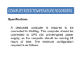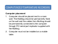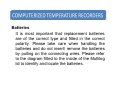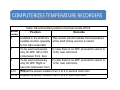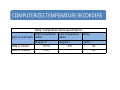
1
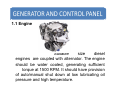
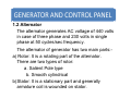
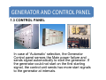
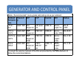
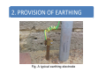
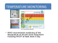
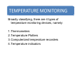
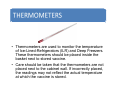
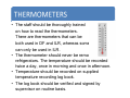
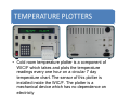
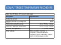
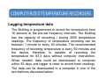
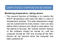
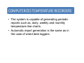
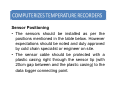
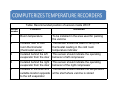
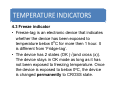
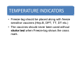
Dr. Vitthal S. Bandal B. E. (Electrical) (Gold Medalist) M. E. (Electrical) (Power Systems), Ph.D. (IIT Bombay) Associate Professor in Electrical Engineering Govt. College of Engineering, Pune Learning Objectives 1. 2. 3. Cold rooms should be provided with continuous quality power supply. The capacity of a generator as power supply backup in the event of grid power supply failure should be adequate to cover the power requirements as per numbers, types and sizes of cold rooms installed in the vaccine store. Also adequate provisions of fuel supply, repair and maintenance should be made available on time. This section guides users on quality of electrical connections and amenities required for cold rooms to function effectively as well as on technical specifications of generators and their maintenance. 1. Generator and control panels 2. Standards of electrical connections 3. Sizing, repair and maintenance of generators 4. Provisions of earthing • To keep the WIC/F units running in the events of mains power failure, a stand by generator is provided. In case of power failure, the generator can start “automatically” • A Diesel Generating set has three parts, Engine, Alternator and control panel connected together. The KVA rating of the alternator and panel depends upon the power required to run the cooling units and how many cooling units are connected/functioning at a given time. 1.1 Engine Suitable size diesel engines are coupled with alternator. The engine should be water cooled, generating sufficient torque at 1500 RPM. It should have provision of auto/manual shut down at low lubricating oil pressure and high temperature. 1.2 Alternator The alternator generates AC voltage of 440 volts in case of three phase and 230 volts in single phase at 50 cycles/sec frequency. The alternator of generator has two main parts:a) Rotor: It is a rotating part of the alternator. There are two types of rotor: a. Salient Pole type b. Smooth cylindrical b)Stator: It is a stationary part and generally armature coil is wounded on stator. Alternator 1.3 CONTROL PANEL In case of ‘Automatic’ selection, the Generator Control panel senses the Main power failure and sends signal automatically to start the generator. If the generator could not start on the first starting signal, the control-unit sends two more start signals to the generator at intervals. Even then if the generator could not start, ‘Generator failure alarm is given (This can be put off by bringing selector switch for mode of operation to ‘STOP’ position, once). When the generator starts and run, the power from the generator is connected, with a delay, to the cooling / freezing unit – selected. When the mains power returns, the generator power supply is cut off and the Mains power is reconnected to the unit and also the generator is stopped automatically, with a delay, by the Generator Control Panel. Whenever the generator runs, the run hour counter registers the time of running of the generator. Note: - Also in the case of single-phase and low/high voltage in the Mains supply, the same is disconnected and the generator power to the selected WIC/F unit automatically. Generator Control Panel also monitors the functioning of the Engine. In case of Low lube Oil Pressure or High Engine Temperature it stops the engine and gives alarm. Important: The 12V battery on the generator is not only for starting the engine, but also for supply of 12V DC to the Generator Control Panel. So, if the battery voltage is low or the battery is discharged, both will not function properly. As a result, in case of power failure neither the generator will start automatically nor will it be possible to start manually. 1.4 Installation 1. The DG set should be installed on a solid concrete foundation having at least six reinforced foundation bolts. 2. Keep at least 1 meter away from the surrounding walls and other equipments to prevent fire hazards and provide adequate ventilation. 3. The DG set should operate only on the leveled surface. Keeping set on unleveled surface may result fuel spillage and oil pump may not get the lubricating oil, causing seizer of crank shaft bearings. 1. 2. 3. 4. Never run the DG set in close area, the exhaust gases contains poisonous carbon mono-oxide. Ensure the smoke is released in the open area at a sufficient height outside the building where WIC/F is installed. Keep DG set in locked condition so that no unwanted person may access the DG set. The DG set should be earthed properly. Never run the set without proper earthing. Always use recommended lubricating oil by the manufacturers depending upon the ambient temperature. For the selection of the lubricating oil grade, anticipated lowest temperature at the time of start should be considered in the winter season and highest temperature of the day during summer season. Table : Recommended* mono-grade lubricating oils as per ambient temperature Ambient Viscosit B.P H.P Castrol IOC Caltex Tempera y ture -15 to 5oC -5oC to +10oC +10oC to +45oC Above +45oC SAE 10W B.A Super oil 10W SAE 20W B.A HP prem. CRB 10 10 Servo super 10 ML-B 10W HDX 20 CRB 20 Super oil 20W SAE 30W B.A Super oil 30W Servo ML-B 20 ultra 10W HDX 30 CRB 30 SAE 40W B.A Super oil 40W HDX/ MILCY 40 CRB / D 40 Servo super/ pride 30W Servo ML-C 30 ML-C 40 super/ pride * Consult the service manual of the DG set provided by the40W manufacturer & follow the recommendations • Earthing, commonly referred to as grounding is an electrical safety measure; it is essential and mandatory to provide ‘earthing’ to all the electrical appliances to ensure that any exposed conductive part of the appliances does not reach a dangerous level of electrical connection between the exposed metallic parts of an installed electrical appliance and the EARTH, regarded to have zero potential. Proper earthing provides an alternative and easy path for leakage or faulty current to flow safely to earth. • A proper earthing system should have minimum electrical resistance, good corrosion resistance and ability of conducting/ dissipating faulty electric current. Fig. A typical earthing electrode 2.1 Type of earthing The user may choose any one of the following types of earthing: 1. G I Pipe earth electrode. 2. Plate earth electrode. 3. Strip or conductor earth electrode. Moist soil acts as an excellent electrolyte, which means that it encourages severe corrosion of metal systems that are laid underground. As a noble metal, copper is resistant to this kind of corrosion. Plain, galvanized or even copperplated iron components on the other hand corrode and decompose. This is why various standards specify that only plain copper provide best alternative used for earth connections that are laid underground. 2.2 Earthing procedure G.I Pipe earthing In this system of earthing, a G.I pipe is required with diameter of 38mm, 2 meter (7 feet) of length and with bottom end cut in ‘V’ shape. The pipe should have holes of 12 mm diameter and the pipe is embedded vertically in ground to work as earth electrode. Items required for this type of earthing are: 1. Couplings for connecting 38mm diameter and 20mm diameter pipes 2. G.I Pipe of 20mm diameter and length 1.5 feet 3. One set of G.I nut and bolt of 8mm 4. G.I wire as per the electric load 5. Charcoal 6. Salt 7. Soil/ sand 8. Cement, Sand, gravel or Bricks 9. Cast iron plate for covering 2.3 Installation Procedure The earthing electrode should be situated at least 1.5 meter (5’) away from the building whose electrical system is being earthed. Ground depth depends upon the soil condition; there is no hard and fast rule for this. Dig the selected area of size 2’x2’ and 2 meter deep. Sprinkle sufficient quantity of water in the bottom and surrounding walls to make the walls wet. Put the G.I Pipe inside the pit so that end touches bottom of the pit. The earth strip or wire should be of same material as that of earth electrode. 1. 2. 3. 4. Fill up the bottom layer of the pit with Coal, salt, and sand (continue and make 3 stacks with each stack having a layer of coal, salt and soil). This should be filled around the G.I Pipe for effective earthing. Finally fill the pit with sand and pour plenty of water and allow the pit to soak it. If required add more water to the pit. The size of the earth wires should not be either less than (14SWG) or half of the installation conductor size. Leave earth electrode (G.I Pipe) exposed 1 foot above the ground level. Provide a manhole and brick masonry structure of size 12”x12”x18”(300mm x 300mm x 457mm) around the rod with hinged cast iron cover. 1. The earth wire is connected with the G.I Pipe above the ground level. Earthing can be checked by carrying out continuity test. 2. All joints in the earth wire should be firmly done with nut and bolts of the same material as of earth wire. 3. Earth resistance is measured by earth tester. 4. For other two types of earthing, similar method can be implied by changing the GI pipe with copper strip or copper plate. 1. Why a generator set is necessary with WIC/F. 2. What are the key components of a generator? List out them with their functions. 3. What are the key criteria to choose the size of a generator? 4. What precautions should be taken while installing the generator? 5. Write down the maintenance schedule of a generator. 6. Why earthing of a cold chain equipment is necessary? Write down the main accessories required to earth a WIC/F and generator. Learning objectives Monitoring of a cold room temperature ensures that the vaccine has been kept in safe and secured conditions. Many variety of temperature monitoring devices are available in the market with advance technology that allow remote monitoring of WIC/F. Temperature monitoring devices, especially the mechanical devices require regular maintenance. This section provides user with technical guidance on various types of temperature monitoring devices, procedure to operate them. A list of spare parts and serviceable components of temperature monitoring devices is also included. • Temperature monitoring devices • How to use these devices • Operation of continuous data loggers and wireless monitoring • Vaccine vial monitor • Monitoring temperature during vaccine transportation • Maintenance of temperature monitoring devices Fig. Temperature Monitor • WHO recommends monitoring of the temperature of all cold chain equipment including WIC/F at least twice a day. • It is critical to ensure that the quality (potency) of vaccine is maintained at national and regional stores by stocking the vaccines at recommended temperatures. It is very critical, therefore, to monitor the temperatures of WIC/F round the clock. • Temperature monitoring is regular and continuous process. There are several ways of monitoring the temperature and some methods are more relevant for monitoring temperature of cold rooms at national/state/regional vaccine stores, while others are more relevant at periphery level or for transportation. Broadly classifying, there are 4 types of temperature monitoring devices, namely: 1. Thermometers 2. Temperature Plotters 3. Computerized temperature recorders 4. Temperature indicators • Thermometers are used to monitor the temperature of Ice-Lined-Refrigerators (ILR) and Deep Freezers. These thermometers should be placed inside the basket next to stored vaccine. • Care should be taken that the thermometers are not placed next to the cabinet wall. If incorrectly placed, the readings may not reflect the actual temperature at which the vaccine is stored. • The staff should be thoroughly trained on how to read the thermometers. There are thermometers that can be both used in DF and ILR, whereas some can only be used in ILR. • The thermometer should never be removed from refrigerators. The temperature should be recorded twice a day, once in morning and once in afternoon. • Temperature should be recorded on supplied temperature recording log book. • The log book should be verified and signed by supervisor on routine basis. • Cold room temperature plotter is a component of WIC/F which takes and plots the temperature readings every one hour on a circular 7 day temperature chart. The sensor of this plotter is installed inside the WIC/F. The plotter is a mechanical device which has no dependence on electricity • The sheet/chart should be replaced every week. The weekly sheet should be marked clearly with starting and ending date, reference of WIC/F and name of the store. • Plotter requires regular maintenance in terms of replacement of plotting pen/ink. This might need replacement every 6 months. The best way to monitor the WIC/F temperature is through computerized temperature monitoring system. This kind of monitoring will lead to real time temperature monitoring for 24 hrs. It gives automatic alert on landline, mobile phones, Fax, emails and alarms/hooters. Computerized monitoring system is of two types: 1. Wired temperature monitoring system (e.g. Multilog) 2. Wireless temperature monitoring system (e.g. Cobalt) 3.1 Multi-channel computerized temperature monitoring system The Multilog has been designed to perform two major tasks. It records the temperature from installed and connected sensors at a defined frequency. • The data logger is triggered ON to start recording through the computer software. The data logging however does not require the computer intervention. The computer is required to trigger the data logger to start recording and to download the recorded temperature readings. The computer intervention is also required to reset the data logger to clear the memory. The second function of Multilog is to raise alarms in case of temperature violation. Table: Specifications of 16 sensor data logger Description Number of sensors Specification 16 Maximum number of readings per sensor Temperature recording range -30 to +70 Deg Celsius Equipment operating temperature -30 to +70 Deg Celsius Accuracy of temperature Other features 2000 +/- 0.5 Deg Celsius Data automatic download on computer, Instant temperature monitoring, raise audible and dial out alarm on temperature violation Logging temperature data The Multilog is programmed to record the temperature from 16 sensors at the pre-set frequency intervals. The Multilog has the capacity of recording / storing 2000 temperature readings. The frequency of temperature recording can be between 1 minute to every 60 minutes. The recommended frequency of recording temperature is every 60 minutes and the device, therefore, is capable of recording the temperature for 83.3 days without computer intervention. When needed, data could be downloaded to computer within 83 days and logger is reset to record fresh readings. The data can be downloaded to a computer in one of the two fashions discussed below: Monitoring temperature, raising alarms • The second function of Multilog is to monitor the WIC/F temperature and raise the alarm in case of temperature violation. The safe temperature range can be customized for every sensor. User can also define which sensors are critical to raise alarm. For the alarms to function, the “instant monitor” feature of the software should be turned on, and the computer should be ‘ON’ and running all the time. Alarms do not function when the computer has been switched off. • When the instant monitor is ON, the temperature of all the installed and connected sensors is shown on the computer. The temperature of all the sensors is refreshed on the computer monitor every 1 hour or as frequent as 30 seconds as specified by the user. • Apart from raising the audible alarm through the internet speaker of the Multilog and through the connected speakers of the computer, the Multilog also raise the dial-out alarm through the device called auto-dialer. The auto-dialer should however, be connected to an active phone line or a SIM card and should be in “ARMED” or “Activated” state. The autodialer alarms users in form of a phone call or a SMS in case of temperature violation. The dialer can be configured to dial-out and alarm up to 6 people (6 phone numbers). The dialer has an online acknowledgement feature and stops alarming people once the recipient of the call acknowledges the call. Organization of Multilog • The 16 sensors Multilog is designated to read the temperature from 16 sensors. There are 4 boards inside the Multilog. Each board connects to 4 sensors each. Each board is connected to computer using serial port. This requires 4 free serial ports at computer end. PCs are normally not equipped with 4 slots of serial ports, hence, a serial port multiplier card is supplied with the Multilog. This card should be inserted in the free PCI slot. The card comes with a CD-ROM of software driver files. The software driver files once installed, adds 5 new ports to the computer hardware (1 for the serial port multiplier and 4 additional serial port slots). Each of these newly added serial ports connects to the Multilog boards. The hardware setup is complete by connecting all the 16 sensors (4 sensors each in 4 boards) to Multilog and connecting 4 serial cables from Multilog to computer serial port Multiplier. Specifications A dedicated computer is required to be connected to Multilog. This computer should be connected to UPS (for uninterrupted power supply) as the computer should be running 24 hours of time. The minimum configuration required is as follows: 1. A desktop with Pentium IV processor and Intel based motherboard (Multilog cannot be operated from a laptop) 2. 256 MB of RAM 3. 40 MB of free space 4. Free PCI slot to insert the serial port card 5. 1KVA UPS with external battery bank to provide power backup of more then 12 hours 6. 1 color printer (LaserJet or DeskJet) 7. Speakers (not mandatory, but this helps in raising audible alarm intensity) Computer placement 1. Computer should be placed next to a room wall. The Multilog should be permanently fixed on the wall and the cables from Multilog should be permanently connected to the computer through PCI serial port replicator supplied with the Multilog. 2. Computer must not be installed on a mobile table. Batteries It is most important that replacement batteries are of the correct type and fitted in the correct polarity. Please take care when handling the batteries and do not insert/ remove the batteries by pulling on the connecting wires. Please refer to the diagram fitted to the inside of the Multilog lid to identify and locate the batteries. Battery Type 1: (Part No: MLBATT1) • Is a re-chargeable battery and should be replaced every 4 years with a similar type of battery. • CAUTION – Never fit an ordinary type of PP3 battery. • This battery has a Velcro patch on its side to hold it in place inside the Multilog case. To replace the battery ease off the terminal connector and then gently ease the battery from its Velcro restraint. Battery Type 2: (Part No: MLBATT2) These are special 3.7V lithium thionyl-chloride battery packs. It is recommended that they should be replaced annually. To replace a battery gently ease the battery connector from the circuit board. Auto –Dialer Batteries (Landline Based) Auto-dialer is powered by 3 replaceable size AA manganese alkaline batteries. 3.2 Wireless temperature data logger • The best way to monitor the cold room temperature is through computerized temperature monitoring system. This monitoring will lead to real time temperature monitoring for 24 hrs. It gives automatic report generation (daily, weekly and monthly), automatic alert on landline, mobile phones, Fax, emails and alarms/ hooters. • Wireless temperature monitoring system has been especially designed to monitor the temperature of cold rooms and freezer rooms. • The sensors are placed at ideal location inside the WIC/WIF which is connected by wire to the radio module installed outside the cold room. Each module is capable of accommodating 8 sensors. Radio module transmits the real time data through radio frequency to radio receiver. Radio receiver is connected to computer where the data is interpreted. • The system is capable of recording temperature at user defined frequency which can range from every 1 minute to every 1 hour. The ideal frequency of recording the temperature is every 1 hour. • Radio modules and radio receiver works with electrical power supply with a standby battery backup. • The standby battery should be checked on periodic basis. This may need replacement every 6 months. • The system is capable of generating periodic reports such as, daily, weekly and monthly temperature line charts. • Automatic report generation is the same as in the case of wired data loggers. Sensor Positioning • The sensors should be installed as per the positions mentioned in the table below. However expectations should be noted and duly approved by cold chain specialist or engineer on site. • The sensor cable should be protected with a plastic casing right through the sensor tip (with 20cm gap between and the plastic casing) to the data logger connecting point. Table: Recommended position of sensors inside WIC/F Sensor number Position Remarks 1 Room temperature To be installed in the area used for packing the vaccine 2 Installed next to cold room thermometer (thermostat sensor) This sensor should be used to verify the thermostat reading in the cold room temperature indicator 3 Installed behind the left evaporator from the door This sensor should indicate the operating behavior of left compressor 4 Installed behind the right evaporator from the door This sensor should indicate the operating behavior of the right compressor 5 Installed in the shelf at a This sensor should indicate the temperature suitable location opposite at the shelf where vaccine is stored to the left evaporator Table: Recommended position of sensors inside WIC/F Sensor number Position Remarks 6 Installed in the shelf at a This sensor should indicate the temperature suitable location opposite at the shelf where vaccine is stored to the right evaporator 7 To be used exclusively only for WIF: left or first compressor from door 8 9-12 In case there is no WIF, proceed to sensor 9To be used exclusively only for WIF: Right or 12 for next cold room second compressor from door the sensor location from 3 to 6 in second cold room Repeat 13-16 Repeat the sensor location from 3 to 6 in third cold room In case there is no WIF, proceed to sensor 912 for next cold room Table: Temperature alarm specifications Type of cold room High temperature alarm Low temperature alarm Delay Degree C Degree C (mins) Walk in Cooler +100C 20C 60 Walk in Freezer -100C - 60 4.1 Vaccine Vial Monitor (VVM) • Vaccine vial monitors are heat-sensitive chemicals applied to the vial label or cap. They show whether the vial has been exposed to excessive heat since leaving the factory. • If the square is lighter than the circle, the vial can be used unless the expiry date, or other instructions dictate that the vial should be discarded. 4.2 30 days temperature indicator • Fridge tag is a 30 days temperature logger which is especially designed for ILRs. This device records the Maximum and minimum temperature of every day for 30 days. • Device also indicates whether there has been any alarming temperature situation in the past 30 days. In case there is a high or low temperature violation, the device shows “ALARM” on LCD screen. If there have been no instances of temperature violation, the “OK” comes on screen. • Fridge-Tag has two modes, namely monitoring mode and reading mode. The device is always in monitoring mode, unless user presses the “READ” button to get into read mode. • Once the device in read mode, user can press “READ” button to go through the temperature history of past 30 days. The cycle of reading the temperature history continues with “Today’s Maximum” followed by “Today’s Minimum”, followed by “Yesterday’s Maximum”, followed by “Yesterday’s Minimum” and so on it continues for past 30 days. • The device returns back to monitoring mode after 30 minutes of not pressing the read button. • While showing the history, in case of a temperature violation, the device also shows the time in HH:MM format for the duration of violation. Note: Fridge tag is meant ONLY for monitoring the temperature of vaccine stored in +2 to +80C storage 4.3 Freeze indicator • Freeze-tag is an electronic device that indicates whether the device has been exposed to temperature below 00C for more then 1 hour. It is different from ‘Fridge-tag’. • The device has 2 states (OK (√)and cross (x)). The device stays in OK mode as long as it has not been exposed to freezing temperature. Once the device is exposed to below 00C, the device is changed permanently to CROSS state. • Freeze-tag should be placed along with freeze sensitive vaccines (Hep.B, DPT, TT, DT etc.) • The vaccines should never been used without shake test when Freeze-tag shows the cross mark. 1. What is the difference between temperature recorder and temperature indicator? 2. How does hourly recording of temperature of WIC/WIF helps in diagnosing a problem? 3. What are the salient features of wireless datalogger?