1
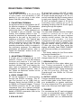
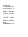
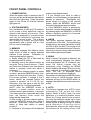
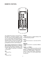
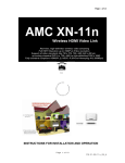
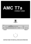
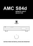
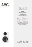
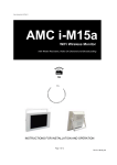
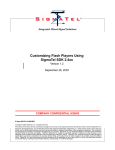
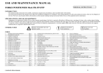
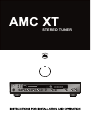
STEREO TUNER
IA
DAB
APPLICATION AND FEATURE LIST
Features of the AMC model XT
* The AMC model XT tuner is designed to meet professional quality standards for
reception of AM and FM broadcasts.
* Select grade components are utilized throughout the circuit design with special
emphasis on components within the audio path to assure stable, consistent
performance and superb sound quality.
* Quartz referenced phase locked loop (PLL) circuitry assures precise tuning.
* Sophisticated surface acoustic wave (SAW) filter at antenna input guards against
interference and noise.
* Specially selected linear phase IF filters combined with other matched circuit
components contribute to the ultra low distortion and excellent stereo separation.
* A total of 30 AM and FM stations in any combination may be stored for recall. The
preset memory is nonvolatile and will retain stored entries for more than two weeks in
the event of power loss.
* A MONO mode is provided to minimize background noise when listening to weak
stations.
* Built-in RDS function: Provides automatic reception and display of data provided by
stations utilizing the Radio Data System (RDS) in their broadcasts (RBDS in USA).
* DAB ready for future up-gradation.
2
REAR PANEL CONNECTIONS/FRONT PANEL CONTROLS
REAR PANEL
2
8
3
7
6
4
1. RECEPTACLE & FUSE (T1AL 250V)
2. FM ANTENNA TERMINAL
3. AM ANTENNA TERMINAL
4. RS232
5. IR IN & IR OUT
5
9
1
6. ZONE
7. REGION
8. OUTPUT JACKS
9. TRIGGER
FRONT PANEL
8 9
10 11
DAB
1
2
3
1. POWER SWITCH AND POWER
INDICATOR
2. STATION PRESET
3. MEMORY
4. AM/FM
5. MONO
4
5
6. AUTO
7. TUNING
8. TEXT
9. TIME
10. PROGRAM
11. TYPE
3
6
7
REAR PANEL CONNECTIONS
1. AC RECEPTACLE
The AC RECEPTACLE is for you to plug
in with power cord attached in the
packing or you can plug in with other
power cord with your preferences.
IR signal from rooms or IR OUT of other
units can be connected the 3.5mm mini
IR IN jack on the rear panel of XT. So, XT
can be controlled by the IR remote control
in each room through IR sensor. There is
IR OUT as buffered output of IR IN for
controlling units hooking up to XT or
operating as daisy chain for the IR signal
passing through the system.
2. FM ANTENNA TERMINAL
An antenna must be connected to the XT
for effective reception of FM broadcasts.
A ribbon wire "folded dipole" antenna,
which looks like a "T" when stretched out,
is included to get you started. For best
results, the crossbar portion of the "T"
should be stretched out horizontally and
attached to the wall, to the back of a
cabinet or on the floor. The "Vertical" part
of the "T" should be connected to the 75
Ohm FM antenna input on the rear panel
o f the t u n e r b y u s i n g t h e 7 5 O h m
matching transformer which is included in
the accessory package. For additional
information on antenna options, refer to
"Notes On Antennas" section at the end
of this manual.
6. ZONE 1 2 3 4 SWITCH
You can select different remote command
c o d e s t o c o n t r o l u p t o f o u r XTs
independently with the same wireless
remote control system. Set the Zone
switch to the number 1-4 that
corresponds to the zone you programmed
with the remote control handset (see
Remote Control). When you turn on the
XT after you move the Zone switch the
display will briefly flash ZONE CHANGE
with the zone number you just selected.
Notes:
- The factory setting for the Zone switch
and remote handset are 1.
- The Zone switch should only be
changed when the XT is turned off.
3. AM ANTENNA TERMINALS
A single wire is supplied as an AM
antenna. Connect it to the AM antenna
terminal and position it for best AM
reception by inserting one lead into the
terminal marked "AM" and leaving the
other lead unconnected. For additional
information on antenna options, refer to
the "Notes on Antennas" section at the
end of this manual.
7. REGION SWITCH
Set the switch for the region where you
live. Tuning increments in the USA
position (North America) are 200KHz for
FM and 10KHz for AM. Turing increments
in the EU position (Europe, UK,
Scandinavia) are 50KHz for FM and
9KHz for AM.
4. RS232 CONNECTOR
XT can be hooked to a control system
through the RS232 connector. The XT
can be hooked up to USB Hub or
Ethernet Switch through RS232 to USB
or RS232 to Ethernet adaptor. Through
the RS232 connector, the XT can accept
commands from your system controller
and feed back status to be displayed. For
details of RS232 commands, refer to the
appendix I enclosed.
8. OUTPUT JACKS
Connect standard audio cables from the L
and R output jacks to the Tuner input on
your preamplifier or system controller.
You may connect the XT to any line-level
input, even if the input isn't label "tuner".
9. TRIGGER
For convenience the XT can be triggered
to turn on automatically when a suitable
voltage is applied to its Trigger IN jack.
When automatic turn on is selected the
5. IR IN & IR OUT
4
XT front panel Power button is disabled
so that on/off is determined solely by the
triggering preamp or controller.
Man Position
When the Man Auto switch is in its Man
(manual) position, the auto turn on
function is disabled and the XT must be
turned on and off manually with the
Power button on its front panel.
AUTO Position
When the Man Auto switch is set to its
Auto position, the XT is turned on and off
with either an external dc or ac voltage of
3.3V to 30V from your controller or
preamplifier. When external voltage
ceases the XT will turn off immediately.
The Auto switch position disables the
front panel Power button.
IN (3-30V AC/DC)
The XT 3-30V AC/DC input uses a 2.5mm
dc jack. To trigger the XT, plug one end of
the cord into this jack and the other end
into the source component's trigger
output. Some components may use a
3.5mm trigger output jack, so you may
have to use a 3.5mm jack to 2.5mm plug
adaptor.
OUT (12VDC)
The 12Vdc trigger loop jack lets you
"daisy-chain" the incoming trigger voltage
to an additional XT or other component.
5
FRONT PANEL CONTROLS
stations have been entered.
f. If you change your mind or make a
mistake, it is not necessary to reprogram all
presets in sequence. Reprogram any
preset simply by tuning to the desired
station, press the MEMORY button and
then press the desired preset number.
g. If the MEMORY button is pressed by
accident, it can be deactivated immediately
by pressing again the MEMORY or AM FM
button or simply by waiting 3 to 5 seconds
for automatic deactivation.
1. POWER SWITCH
When the power switch is pressed, the XT
turns on and the small indicator light above
the switch will glow blue. Press the switch
again to turn off the XT and the indicator
light goes out.
2. STATION PRESETS
Any combination of AM and FM stations,
up to a total of thirty selections, may be
stored in the memory of the tuner. Each
selection is assigned to a preset button
and may be recalled by pressing the
appropriate preset button. The memory
will preserve preset assignments
permanently after a power loss or if the
AC line cord is unplugged.
4. AM FM
This button switches between the two
tuning bands: FM or AM. The digital tuning
display shows the tuned frequency in MHz
(for FM) or KHz (for AM). The tuning circuit
maintains a "last station selected" memory,
returning to the previously selected station
when switching between bands.
3. MEMORY
This button engages the Memory Enter
mode which is used to assign selected
stations to the presets. Procedure for
entering stations into memory:
a. Select either the FM or AM band by
pressing theAMFM button.
b. Manually tune to the desired station by
using the Tuning Control buttons. Check
the center tune indicator to be sure that the
station is properly tuned and adjust if
necessary.
c. To store the selected station in preset
number 1, press the MEMORY button, then
press the 0 button and then the 1 button.
(For preset positions 1 through 9, the 0
button should be pressed before the
number is pressed, i.e. 01, 02, 03, etc.
Otherwise, you may have to wait for few
seconds after the 1 to 9 digit is pressed.)
NOTE: After the MEMORY button is
pressed, a preset position must be
selected within approximately 5 seconds.
If no preset position is selected within that
time, the Memory Enter mode will
automatically deactivate.
d. After tuning to the next desired station,
press the MEMORY button then, within 5
seconds, press the 0 button and the 2
button to store that station in preset
position 2.
e. Continue in this manner till all selected
5. MONO
When a stereo FM signal is detected, the
tuner automatically switches into stereo
mode and displays the "S". However, very
weak FM station signals may be
excessively noisy. Pressing the MONO
button disables the stereo FM circuits in the
tuner resulting in significant reduction of
noise. The "ML" is displayed when
enforced mono operation is engaged.
Remember to disengage the MONO button
when tuning to normal stronger stations
because as long as the MONO button is
engaged, broadcasts cannot be received in
stereo.
6. AUTO
This button engages the AUTO mode,
indicated by "(A)" on the left of the
display. When in AUTO mode, the tuner
advances in a station-by-station mode.
When the Tuning buttons are pressed,
the tuner will advance rapidly up or down
automatically stopping at the next station
whose signal is strong enough to assure
good reception. A muting circuit
automatically silences the output during
the advance till the tuning circuits lock
6
When the TYPE button is pressed, the
type of program material will be
displayed, e.g. News, Classic, Pop,
Sport, etc. If the selected station is not
transmitting TYPE information, NONE will
appear in the display.
onto a station. Disengaging the AUTO
button puts the tuner into MANUAL mode
which allows tuning in small steps to
search for weak stations or fine tuning to
minimize interference. The MANUAL
mode partially overrides the scan muting
allowing all stations and interstation noise
to be heard at reduced levels while
tuning. When MANUAL mode is
operating, "(M)" is indicated in the display.
NOTE: TIME, TEXT, PROGRAM and
TYPE are RDS functions. For the areas
or the radio stations do not have RDS
broadcasting, the display may not show
any significant information.
7. TUNING
Tuning up or down the AM and FM bands
is accomplished by pressing either of the
two TUNING buttons. Press the > button
to tune toward higher frequencies or the <
button to tune toward lower frequencies.
When the XT is in MANUAL mode, the
tuning frequency will change in small
steps. When the XT is in AUTO mode, the
frequency will continue to advance rapidly
till the button is released. Observe the
Tuning indicators while finetuning to
obtain maximum signal strength. On FM,
finetune till the centertune indicator is
illuminated.
8. TEXT
When the TEXT button is pressed, a text
message will repeatedly scroll through
the display. If the selected station is not
transmitting a text message, NO TEXT
will appear in the display.
9. TIME
When the TIME button is pressed, the
time is displayed. The first two
characters at the left of the display
indicate AM or PM followed by the time.
If the selected station is not transmitting a
time signal, NO CLOCK will appear in the
display.
10. PROGRAM
When the PROGRAM button is pressed,
the selected station name will appear in
the display. If the selected station is not
transmitting the station name, NO NAME
will appear in the display.
11. TYPE
7
REMOTE CONTROL
OFF
ON
1
2
3
4
5
6
7
8
9
+10
0
AUX
CD
TUNER
PLAY/PAUSE
ZONE
STOP
FM/AM
TRACK
TUNE
PHONO
VOLUME
AUTO
PRESET
MANUAL
DIRECT
RC-S1
An infrared (IR) remote control RC-S1 is
provided for convenient operation of the
XT. The remote control handset provides
most of the similar control functions as
the front panel. RC-S1 is AMC simplified
delicate system remote controller. Not
only it can control XT but also AMC
preamplifiers/receivers and CD players.
FM/AM
Press this button to toggle between FM
and AM frequency bands.
AUTO
Press this button to activate AUTO
TUNE.
MANUAL
Press this button to activate MANUL
TUNE.
T h e r e m o t e c o n t r o l has a r a n g e o f
approximately 20-25 feet (6-7.5 meters).
Use only AAA alkaline batteries in the
handset and insert them according to the
+ and - polarity markings in the battery
compartment.
TUNE > and TUNE <
Tuning up or down the AM and FM
bands is accomplished by pressing either
of the two TUNE buttons. Press the >
button to tune toward higher frequencies
or the < button to tune toward lower
frequencies.
ON
To turn XT on.
OFF
To turn XT off.
8
ZONE
You c a n s e l e c t d i f f e r e n t r e m o t e
command codes to control up to four XTs
independently with the same wireless
remote control system. Program the
remote handset to the number 1-4 that
corresponds to the Zone switch number
on the XT.
Note the remote handset will not operate
the XT unless its zone number matches
the Zone switch setting. The factory
settings for the remote handset and the
unit's Zone switch are 1.
To set the remote zone code, press both
the zone key and the key 1~4 which
corresponds to the setting of the XT Zone
switch. These keys must be pressed
simultaneously for about 1.5 seconds.
CD TUNER AUX PHONO
These four buttons select which input
signal (CD, TUNER, AUX and PHONO) is
fed to the inputs of AMC preamplifier or
receiver.
When CD is pressed, the numbered
keys (0-9 and 10) allow direct selection of
desired track.
VOLUME > and VOLUME <
These two buttons are used for adjusting
the overall loudness level of the sound. It
has no effect on the level of the signals
fed to the TAPE OUT jacks for tape
recording.
PLAY/ PAUSE
For AMC CD players use, press this
button to toggle between PLAY and
PAUSE.
0 1 2 3 4 5 6 7 8 9
The numbered keys perform several
functions when combined with PRESET,
DIRECT and CD buttons. See below:-
STOP
For AMC CD players use, to stop CD
while playing.
PRESET
W h e n t h i s b u t t o n i s p r e s s e d , the
numbered keys can be for direct access
to each stored preset station. Presets 1-9
are displayed as P01, P02, P03, and so
on. To select station presets 10-30, press
the tens place key first. For example, to
select 26, first press key 2, then press key
6.
TRACK > and TRACK <
For AMC CD players use, to let you set
the desired track for listening.
DIRECT
W h e n t h i s b u t t o n i s p r e s s e d , the
numbered keys can select the broadcast
frequency of the station you wish to
receive. First press the DIRECT key, then
the numbered keys corresponding to the
station.
In USA: to receive FM 103.7, press
DIRECT, 1, 0, 3, 7, 0.
IN Europe: to receive 103.75, press the
DIRECT key, then press keys 1, 0, 3, 7, 5.
Note if you enter an incomplete
frequency, such as 1, 0, 3, 7 which is
missing the final 0 or 5, there will be a
short pause while the XT fills in the
missing number and finds the station.
9
SPECIFICATIONS
FMTUNER SECTION
Input Sensitivity MONO 30 dBTHD+N.......................................11.3 dBf (1.0 uV/75 ohm)
MONO 50 dB S/N................................................15 dBf (1.5 uV/75 ohm)
STEREO 50 dB S/N.............................................37 dBf (20 uV/75 ohm)
STEREO 60 dB S/N.............................................47 dBf (60 uV/75 ohm)
Capture Ratio (45 and 65 dBf)...............................................................................<1.5 dB
AM Rejection (45 and 65 dBf).................................................................................>60 dB
SelectivityALTERNATE CHANNEL.........................................................................65 dB
Image Rejection.......................................................................................................80 dB
RF Intermodulation..................................................................................................60 dB
IF Rejection..............................................................................................................90 dB
Subcarrier Suppression (19 and 38 kHz)..................................................................60 dB
THD at 100% Modulation MONO 1 kHz..................................................................0.08%
100 Hz-6 kHz....................................................................0.2%
STEREO 1 kHz..................................................................0.08%
100 Hz-6 kHz....................................................................0.3%
Signal/Noise Ratio
MONO...........................................................................>78 dB
(at 65 dNf, 1HFweighted) STEREO.......................................................................>74 dB
Frequency Response
30 Hz-15 kHz................................................................+/0.5 dB
Stereo Separation
1 kHz...............................................................................50 dB
30 Hz-10 kHz.......................................................................35 dB
Output Level.........................................................................................................530mV
AM TUNER SECTION
Useable Sensitivity...................................................................................................10 uV
Selectivity.................................................................................................................30 dB
Image Rejection.......................................................................................................45 dB
IF Rejection..............................................................................................................35 dB
Signal/Noise Ratio (30%modulation, 50mV input)...................................................45 dB
THD..........................................................................................................................0.5%
Output Level..........................................................................................................125mV
Dimensions ( W x H x D) ....................................................................... 430 x 82 x 300 mm
Power consumption ................................................................................................. 15 W
Weltronics Corp. reserved the right to improve its products at any time. Specifications are
subject to change without notice.
10
NOTES ON ANTENNAS
In most cases, the exceptional sensitivity of AMC tuner circuits results in achieving very
good performance with only a ribbonwire dipole antenna. However there are limitations
to a dipole. It is not effective at rejecting multipath distortion and other forms of FM
interference and it cannot easily be oriented for optimizing its reception pattern. Other
possible solutions, in order of increasing cost, include:
1. Indoor TV antenna (rabbitears) without extra coils or tuning switches
* Will NOT improve the strength of weak signals.
* Has solid metal tuned elements that can be rotated.
* The two elements should be extended to a total length of 30 inches (75cm) and
oriented horizontally or at a shallow angle less than 45 degrees upward.
* The antenna connecting wire should be connected to the tuner 75 Ohm antenna
terminal using the matching transformer included in the tuner accessory package.
* After selecting a station, rotate the antenna for best reception.
2. Indoor TV antenna (rabbitears) with a tuning switch
* Will NOT improve the strength of weak signals.
* May reduce some types of FM interference, such as reflected multipath signals.
3. Electrically tuned indoor antenna
* Will NOT improve the strength of weak signals.
* May further reduce some types of FM interference, such as reflected multipath signals.
4. Outdoor antenna
* Provides largest selection of stations and best reception with lowest noise and
distortion.
* Narrower directional pattern more effectively rejects reflected multipath signals.
* Signal strength is directly proportional to the antenna height above the ground.
* May be mounted to a tall mast or to a roof.
* Because TV antennas are purposely designed to be weak at FM frequencies, to
lessen interference to TV signals, a directional FM only antenna will provide best
results.
* FM only antenna should be mounted as high above ground as practical and at least
two meters (7 feet), both horizontally and vertically away from other antennas.
* Can be mounted on a rotor to allow aiming at stations located in different directions
(more than 90 degrees apart).
* Use shielded lead in wire rather than plain "twinlead" wire for better performance,
longer life and protection from the weather.
* Disconnect any indoor antenna from the tuner before connecting the outdoor antenna.
CAUTIONS:
* Avoid power lines when locating and installing antenna
* Include a lightning arrestor in the installation to protect both yourself and the tuner
from potential danger during electrical storms.
OUTDOOR AM ANTENNA
* To improve AM reception, a "longwire" outdoor AM antenna may be installed.
* A "longwire" antenna is simply a straight wire which may vary in length from a few feet
up to about 100 feet (30 meters).
* Must be mounted parallel to the earth and should be located as high above the ground
as convenient.
* Connect to the tuner at the AM antenna terminal.
* Connect another wire from the Ground terminal to a true "earth" ground, such as a
copperplated rod driven several feet into the earth. Alternate grounds include a
coldwater pipe, a steam radiator or even the third hole of a modern electrical wall
socket.
11
SAFETY INSTRUCTION
16. DAMAGE REQUIRING SERVICE
1. READ INSTRUCTIONS
All the safety and operating instructions should be read
before the appliance is operated.
2. RETAIN INSTRUCTIONS
The safety and operating instructions should be retained for
future reference.
3. HEED WARNINGS
All warnings on the appliance and in the operating instructions
should be adhered to.
4. FOLLOW INSTRUCTIONS
All operating and use instructions should be followed.
The appliance should not be used near water - for example,
near a bathtub, washbowl, kitchen sink, laundry tub, in a wet
basement, or near a swimming pool, etc.
6. CARTS AND STANDS
The appliance should be used only with a cart or stand that is
recommended by the manufacturer.
7. WALL OR CEILING MOUNTING
17. POWER LINES
(APPLIES TO TUNERAND RECEIVERS ONLY)
An outdoor antenna should be located away from power lines.
5. WATER AND MOISTURE
6A. An appliance and cart combination should be
moved with care. Quick stops, excessive force,
and uneven surfaces may cause the appliance
and cart combination to overturn.
The appliance should be serviced by qualified service
personnel when:
a) The power-supply cord or the plug has been damaged; or
b) Objects have fallen, or liquid has been spilled into the
appliance; or
c) The appliance has been exposed to rain; or
d) The appliance does not appear to operate normally or
exhibits a marked change in performance; or
e) The appliance has been dropped, or the enclosure is
damaged.
PORTABLE CART WARNING
S3125A
This equipment is not designed for use mounted on a wall or a
ceiling.
8. VENTILATION
The appliance should be situated so that its location or position
does not interfere with its proper ventilation. For example, the
appliance should not be situated on a bed, sofa, rug, or similar
surface that may block the ventilation openings, or placed in a
built-in installation, such as bookcase or cabinet that may
impede the flow of air through the ventilation openings.
9. HEAT
The appliance should be situated away from heat sources
such as radiators, heat registers, stoves, or other appliances
(including amplifiers) that produce heat.
18. OUTDOOR ANTENNA GROUNDING
(APPLIES TO TUNERAND RECEIVERS ONLY)
If an outside antenna is connected to the receiver, be sure the
antenna system is grounded so as to provide some protection
against voltage surges and built up static charges.
Section 810 of the National Electrical Code, ANSI/NFPANo.
70-1984, provides information with respect to proper
grounding of the mast and supporting structure, grounding of
the lead-in wire to an antenna discharge unit, size of grounding
conductors, location of antenna-discharge unit, connection to
grounding electrodes, and requirements for the grounding
electrode. See Figure.
a) Use No. 10 AWG (5.3 mm2) copper, No. 8 AWG (8.4 mm2)
aluminum, No. 17 AWG (1.0 mm2) copper-clad steel or
bronze wire, or larger, as a ground wire.
b) Secure antenna lead-in and ground wires to house with
stand-off insulators spaced from 4-6 feet (1.22-1.83 m)
apart.
c) Mount antenna discharge unit as close as possible towhere
lead-in enters house.
d) Use jumper wire not smaller than No.6 AWG (13.3 mm2)
copper, or the equivalent, when a separate antennagrounding electrode is used. See NEC Section 810-21(j).
Antenna Grounding According to
the National Electrical Code
10. POWER SOURCES
The appliance should be connected to a power supply only of
the type described in the operating instructions or as marked
on the appliance.
Antenna Lead
In Wire
11. POWER-CORD PROTECTION
Power-supply cords should be routed so that they are not likely
to be walked on or pinched by items placed upon or against
them, paying particular attention to cords at plugs,
convenience receptacles, and the point where they exit from
the appliance
12. CLEANING
The appliance should be cleaned only as recommended by
the manufacturer.
Ground
Clamp
Electric
Service
Equipment
The power cord of the appliance should be unplugged from the
outletwhen left unused for a long period of time.
Power Service Grounding
Electrode System
(NEC Art 250 Part H)
14. OBJECT AND LIQUID ENTRY
15. SERVICING
The user should not attempt to service the appliance beyond
that described in the operating instructions. All other servicing
should be referred to qualified service personnel.
Grounding Conductors
(NEC Section 810.21)
Ground Clamps
13. NON USE PERIODS
Care should be taken so that objects do not fall and liquids are
not spilled into the enclosure through openings.
Antenna
Discharge
Unit (NEC
Section 810.20)
National Electrical Code
Available from Library, book
stores, or National Fire Protection
Association (Batterymarch Park,
Quincy. MA 02269).
AMC 21-3004
WELTRONICS CORP.
LONDON/L.A.
AMC Web: http://www.amchome.com
PN: 21-2622