1
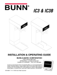
1
2
FILL
RE
IN
MA ER
W
PO
R
TE
WAP U T
IN
1
1
R
O
AV T
FL TPU
OU
2
OR
AV
FL PUT
IN
2
AFPO-2
AFPO-2 SL
AFPO-3
AFPO-3 SL
R
TE T
WA P U
T
OU
R
O
AV T
FL TPU
OU
R
TE T
WA P U
T
OU
1
2
FILL
RE
3
IN
MA ER
W
PO
R
TE
WAP U T
IN
1
OR
AV
FL PUT
IN
OR
AV T
FL TPU
OU
2
R
TE T
WA P U
T
OU
1
2
3
OR
AV T
FL TPU
OU
3
R
TE T
WA P U
T
OU
OR
AV T
FL TPU
OU
R
TE T
WA P U
T
OU
INSTALLATION & OPERATING GUIDE
BUNN-O-MATIC CORPORATION
POST OFFICE BOX 3227
SPRINGFIELD, ILLINOIS 62708-3227
PHONE: (217) 529-6601 FAX: (217) 529-6644
To ensure you have the latest revision of the Operating Manual, or to view the Illustrated Parts
Catalog, Programming Manual, or Service Manual, please visit the Bunn-O-Matic website, at
www.bunn.com. This is absolutely FREE, and the quickest way to obtain the latest catalog and
manual updates. For Technical Service, contact Bunn-O-Matic Corporation at 1-800-286-6070.
28791.0000L 06/12 ©1998 Bunn-O-Matic Corporation
BUNN-O-MATIC COMMERCIAL PRODUCT WARRANTY
Bunn-O-Matic Corp. (“BUNN”) warrants equipment manufactured by it as follows:
1) Airpots, thermal carafes, decanters, GPR servers, iced tea/coffee dispensers, MCP/MCA pod brewers thermal servers
and Thermofresh servers (mechanical and digital)- 1 year parts and 1 year labor.
2) All other equipment - 2 years parts and 1 year labor plus added warranties as specified below:
a) Electronic circuit and/or control boards - parts and labor for 3 years.
b) Compressors on refrigeration equipment - 5 years parts and 1 year labor.
c) Grinding burrs on coffee grinding equipment to grind coffee to meet original factory screen sieve analysis - parts
and labor for 4 years or 40,000 pounds of coffee, whichever comes first.
These warranty periods run from the date of installation BUNN warrants that the equipment manufactured by it will be
commercially free of defects in material and workmanship existing at the time of manufacture and appearing within the
applicable warranty period. This warranty does not apply to any equipment, component or part that was not manufactured
by BUNN or that, in BUNN’s judgment, has been affected by misuse, neglect, alteration, improper installation or operation,
improper maintenance or repair, non periodic cleaning and descaling, equipment failures related to poor water quality,
damage or casualty. In addition, the warranty does not apply to replacement of items subject to normal use including but
not limited to user replaceable parts such as seals and gaskets. This warranty is conditioned on the Buyer 1) giving BUNN
prompt notice of any claim to be made under this warranty by telephone at (217) 529-6601 or by writing to Post Office
Box 3227, Springfield, Illinois 62708-3227; 2) if requested by BUNN, shipping the defective equipment prepaid to an
authorized BUNN service location; and 3) receiving prior authorization from BUNN that the defective equipment is under
warranty.
THE FOREGOING WARRANTY IS EXCLUSIVE AND IS IN LIEU OF ANY OTHER WARRANTY, WRITTEN OR ORAL, EXPRESS OR IMPLIED, INCLUDING, BUT NOT LIMITED TO, ANY IMPLIED WARRANTY OF EITHER MERCHANTABILITY
OR FITNESS FOR A PARTICULAR PURPOSE. The agents, dealers or employees of BUNN are not authorized to make
modifications to this warranty or to make additional warranties that are binding on BUNN. Accordingly, statements by such
individuals, whether oral or written, do not constitute warranties and should not be relied upon.
If BUNN determines in its sole discretion that the equipment does not conform to the warranty, BUNN, at its exclusive option while the equipment is under warranty, shall either 1) provide at no charge replacement parts and/or labor (during the
applicable parts and labor warranty periods specified above) to repair the defective components, provided that this repair
is done by a BUNN Authorized Service Representative; or 2) shall replace the equipment or refund the purchase price for
the equipment.
THE BUYER’S REMEDY AGAINST BUNN FOR THE BREACH OF ANY OBLIGATION ARISING OUT OF THE SALE OF THIS
EQUIPMENT, WHETHER DERIVED FROM WARRANTY OR OTHERWISE, SHALL BE LIMITED, AT BUNN’S SOLE OPTION
AS SPECIFIED HEREIN, TO REPAIR, REPLACEMENT OR REFUND.
In no event shall BUNN be liable for any other damage or loss, including, but not limited to, lost profits, lost sales, loss of
use of equipment, claims of Buyer’s customers, cost of capital, cost of down time, cost of substitute equipment, facilities
or services, or any other special, incidental or consequential damages.
392, AutoPOD, AXIOM, BrewLOGIC, BrewMETER, Brew Better Not Bitter, BrewWISE, BrewWIZARD, BUNN Espress, BUNN
Family Gourmet, BUNN Gourmet, BUNN Pour-O-Matic, BUNN, BUNN with the stylized red line, BUNNlink, Bunn-OMatic,
Bunn-O-Matic, BUNNserve, BUNNSERVE with the stylized wrench design, Cool Froth, DBC, Dr. Brew stylized Dr. design,
Dual, Easy Pour, EasyClear, EasyGard, FlavorGard, Gourmet Ice, Gourmet Juice, High Intensity, iMIX, Infusion Series, Intellisteam, My Café, Phase Brew, PowerLogic, Quality Beverage Equipment Worldwide, Respect Earth, Respect Earth with
the stylized leaf and coffee cherry design, Safety-Fresh, savemycoffee.com, Scale-Pro, Silver Series, Single, Smart Funnel,
Smart Hopper, SmartWAVE, Soft Heat, SplashGard, The Mark of Quality in Beverage Equipment Worldwide, ThermoFresh,
Titan, trifecta, Velocity Brew, A Partner You Can Count On, Air Brew, Air Infusion, Beverage Bar Creator, Beverage Profit
Calculator, Brew better, not bitter., BUNNSource, Coffee At Its Best, Cyclonic Heating System, Daypart, Digital Brewer
Control, Nothing Brews Like a BUNN, Pouring Profits, Signature Series, Tea At Its Best, The Horizontal Red Line, Ultra are
either trademarks or registered trademarks of Bunn-O-Matic Corporation.
2
28791 030912
INTRODUCTION
This equipment supplies a liquid concentrate mixed with water at various ratios to the hoppers on the dispensers. It is for indoor use only on a sturdy counter or shelf.
USER NOTICES
Carefully read and follow all notices on the equipment and in this manual. They were written for your protection.
All notices are to be kept in good condition. Replace any unreadable or damaged labels.
As directed in the International Plumbing Code of the
International Code Council and the Food Code
Manual of the Food and Drug Administration (FDA),
this equipment must be installed with adequate
backflow prevention to comply with federal, state
and local codes. For models installed outside the
U.S.A., you must comply with the applicable Plumbing /Sanitation Code for your area.
00656.0001
00986.0002
Artwork for P/N: 00656.0001
Artwork Rev: A
Drawn: REF
Date: 04/22/10
00824.0002
37881.0000
ELECTRICAL REQUIREMENTS
CAUTION - The dispenser must be disconnected from the power source until specified in Initial Set-Up.
The 120 volt version of this dispenser has an attached cordset and requires 2-wire, grounded service rated 120
volts ac, 15 amp, single phase, 60 Hz. The mating connector must be a NEMA 5-15R.
The 230 volt CE version requires 2 wire, grounded service rated 230V ac, single phase, 50 Hz.
The 200 volt or 240 volt versions require 2 wire, grounded service rated 200 volts ac or 240 volts ac, single
phase, 50 Hz.
(Refer to the dispenser’s data plate for exact voltage requirement.)
CE REQUIREMENTS
• This appliance must be installed in locations where it can be overseen by trained personnel.
• For proper operation, this appliance must be installed where the temperature is between 5°C to 35°C.
• Appliance shall not be tilted more than 10° for safe operation.
• An electrician must provide electrical service as specified in conformance with all local and national codes.
• This appliance must not be cleaned by water jet.
• This appliance is not intended for use by persons (including children) with reduced physical, sensory or mental
capabilities, or lack of experience and knowledge, unless they have been given instructions concerning use of
this appliance by a person responsible for its safety.
• Children should be supervised to ensure they do not play with the appliance.
• If the power cord is ever damaged, it must be replaced by the manufacturer or authorized service personnel
with a special cord available from the manufacturer or its authorized service personnel in order to avoid a hazard.
• Machine must not be immersed for cleaning.
3
28791 071411
Electrical Hook-Up
CAUTION – Improper electrical installation will damage electronic components.
1. An electrician must provide electrical service as specified.
2. Using a voltmeter, check the voltage and color coding of each conductor at the electrical source.
3. Connect the dispenser to the power source.
PLUMBING REQUIREMENTS
This dispenser must be connected to a cold water system with operating pressure between 20 and 90 (138
and 620 kPa) psi from a 1⁄2” or larger supply line. A shut-off valve should be installed in the line before the dispenser. Install a regulator in the line when pressure is greater than 90 psi (620 kPa) to reduce it to 50 psi (345
kPa). The water inlet fitting is 1⁄4” flare.
NOTE - Bunn-O-Matic recommends 1⁄4” copper tubing for installations of less than 25 feet and 3⁄8” for more than
25 feet from the 1⁄2” water supply line. At least 18 inches of an FDA approved flexible beverage tubing, such as
reinforced braided polyethylene or silicone, before the brewer will facilitate movement to clean the countertop.
Tubing is supplied by Bunn-O-Matic (part number 00326-0000). Bunn-O-Matic does not recommend the use of
a saddle valve to install the brewer. The size and shape of the hole made in the supply line by this type of device
may restrict water flow.
As directed in the International Plumbing Code of the International Code Council and the Food
Code Manual of the Food and Drug Administration (FDA), this equipment must be installed with
adequate backflow prevention to comply with federal, state and local codes. For models installed
outside the U.S.A., you must comply with the applicable Plumbing /Sanitation Code for your area.
NOTE - Water pipe connections and fixtures directly connected to a potable water supply shall be sized, installed
and maintained in accordance with federal, state and local codes.
INITIAL SET-UP
NOTE: This refill unit should not be used to initially fill the hopper. Running the motor for extended periods will
trip the thermal switch. The thermal switch will reset, but requires up to 30 minutes of cooling time.
NOTE: Hoses and product container connectors are not supplied. Fitting, clamps and labels are supplied. Make
hose assemblies as required. Refer to PIPING DIAGRAM on page 23.
1. Assemble hoppers with probe housing assemblies to dispenser or modify existing hoppers using template
provided.
2. Make sure probe housing assembly is pushed down into slots on back of hoppers.
3. Install cable assembly to the lower right front of the auto refill box and the probe housing assemblies on the
hoppers. The connectors on the cable pushes in and cap rotates 1/4 turn to lock into position.
4. Run output tubes from auto refill box to the quick disconnects in the hoppers.
NOTE: Make sure numbers on the labels match up. Cable#1 with Hose#1, Cable#2 with Hose#2,....etc.
4
28791 071411
INITIAL SET-UP (cont.)
5. Connect one end of input hoses to the auto refill box and the other end to the product container. Product
container connectors (BIB) are not supplied. Install your own interface.
6. Connect water line to auto refill box. A minimum of 20 psi (138 kPa) is required.
NOTE: Make sure all connections are made before connecting the auto refill box to the power source.
7. Each product container has an ON/OFF refill switch located on the front of the auto refill box. A second switch
for each hopper is at the probe housing assembly. These are 3 position switches, high level, low level and a
center “OFF” position.
8. Place the main ON/OFF switch and ON/OFF refill switches in the “OFF” position.
9. Make sure all hoses are connected. Place the main ON/OFF switch in the “ON” position.
10.Place one of the ON/OFF refill switches in the “ON” position, after a four second delay product will begin to
flow through the hoses into the hopper. Be sure the switch selected is filling the correct hopper, if not, check
the labels. See NOTE in step #4.
11.To test refill circuit short out probes on one of the hoppers with a screwdriver, so that hopper should shut
off. Remove the screwdriver and the hopper will start to fill again after a four second delay. If hopper does
not start to fill, check labels, refer to NOTE in step #4.
12.To change mix ratio refer to MIX RATIO ADJUSTMENTS.
CLEANING
RECOMMENDED WEEKLY CLEANING:
This should be done in conjunction with the recommended weekly cleaning of your machine. The Hoppers must
be empty before starting.
1. Prepare a 1 gallon cleaning solution consisting of 1 gallon of hot water and a sanitizing cleaner which contains
3-5% chlorine based sanitizer. Mix per manufacturers instructions
2. Remove connectors from each concentrate container and place them directly into the cleaning solution.
3. Energize each refill station and allow the cleaning solution to pump through the system into the hoppers. The
cleaning procedure should remove the color stains from the tubing. If not, prepare another gallon of cleaning
solution and repeat.
4. After the cleaning solution has been pumped into the hoppers, rinse the cleaning solution container with hot
water.
5. Fill the cleaning solution container with hot water. Energize each refill station and rinse thoroughly. The amount
of clean hot rinse water should equal the amount of cleaning solution pumped through the system.
6. Empty the hoppers of your machine and follow the recommended cleaning instructions.
NOTE: The hoses should be checked monthly for deterioration, cracks and possible discoloration from some
concentrates. Replace the tubing when necessary.
MIX RATIO ADJUSTMENTS
1.
2.
3.
4.
Remove the top access panel.
Connect the test hose to the “WATER OUTPUT” to be adjusted.
Connect the provided hose (or other suitable water hose) to the “WATER INPUT”.
Ensure water regulator is set at 20 psi(137.9 kPa). Press the “TEST OUTPUT” switch and while water is
flowing from the test hose, check that the gauge reads 20.
5. Place a one-cup container under the test hose. Press the “TEST OUTPUT” switch, and carefully measure and
note the elapsed time from when water first flows form the test hose to when one cup of water has been
dispensed. Hoses and tubing should be primed and free of substantial air spaces and/or bubbles prior to
calibration.
5
28791 121007
MIX RATIO ADJUSTMENTS(cont.)
6. Compare results with chart or formula below.
7. If the time observed is too short or long, turn the needle valve clockwise or counterclockwise, respectively,
a little at a time. Repeat from the preceding step until correct.
Mix ratio (water/flavor)
1+1
2+1
3+1
4+1(see below)
5+1
6+1
Time for FLAVOR OUTPUT (1/2 cup)
assume 20 sec. or obtain time per note below
assume 20 sec. or obtain time per note below
assume 20 sec. or obtain time per note below
assume 20 sec. or obtain time per note below
assume 20 sec. or obtain time per note below
assume 20 sec. or obtain time per note below
Time for WATER OUTPUT (1 cup)
40 sec. or 2 times flavor output time
20 sec. or equal to flavor output time
13.3 sec. or 0.67 times flavor output time
10 sec. or 0.5 times flavor output time
8 sec. or 0.4 times flavor output time
6.7 sec. or 0.33 times flavor output time
NOTE: For a typical adjustment, the time for flavor output in the center column above is assumed to be 20
seconds. A more specific flavor pump output time may be obtained prior to adjustment of the needle valve.
To do so, connect the flavor to be tested to the “FLAVOR INPUT”, and the test hose to the corresponding
“FLAVOR OUTPUT” (make no connection to the “WATER INPUT”). With a one-cup container under the
test hose press the corresponding “TEST OUTPUT” switch, and carefully measure and note the elapsed
time from when the product first flows from the test hose to when one-half cup of the product has been
dispensed. This value may then be used in the formula below. Following flavor pump output measurement,
disconnect the flavor line from the “FLAVOR INPUT” and purge remaining product from the line.
Formula for setting mix ratio: To obtain the time for dispensing 1 cup of water, divide the time it
takes to dispense one-half cup of product by the first number in the mix ratio and then multiply
the result by two.
Example: W=2(F/X) Where W is the time it should take to dispense one cup of water, it took F
seconds (20 here) to dispense 1/2 cup of flavor concentrate, we desire a mix ratio X of 4+1 (X
will be the first number in the mix ratio, 4).
Therefore:
W = 2/(20/4)
W = 2/5
W = 10 seconds
So if it took 20 seconds to dispense one-half cup of flavor concentrate, and a mix ratio of 4 to 1
is required, the needle valve should be adjusted to dispense 1 cup of water in 10 seconds.
NOTE: Hoses and tubing should be primed and free of substantial air spaces and/or bubbles prior
to calibration.
1
RE
3
2
L
FIL
IN
MA R
WE
PO
R
TE
WA UT
INP
1
R
VO
FLA UT
INP
OR
AV
FL TP UT
OU
2
R
TE
WA UT
TP
OU
1
2
3
OR
AV
FL TP UT
OU
3
R
TE
WA UT
TP
OU
OR
AV
FL TP UT
OU
R
TE
WA UT
TP
OU
NEEDLE VALVE
6
P1521
28791 040501
OPERATING CONTROLS
C
B
1
R
3
A
2
L
IL
EF
IN
MA ER
W
PO
R
TE
WAP U T
IN
1
OR
AV
FL PUT
IN
OR
AV T
FL TPU
OU
2
R
TE T
WA P U
T
OU
1
2
P1949
3
A. MAIN POWER ON/OFF
The main power ON/OFF switch is located on the right of the front panel just above the power cord.
OR
AV T
FL TPU
OU
R
TE T
WA P U
T
OU
B. REFILL CIRCUIT ON/OFF
The refill circuit ON/OFF switches are located on the right of the front panel just above the main power switch.
These allow each circuit to operate independently.
C. TEST/OPERATE
The TEST/OPERATE switch is located inside the auto-fill
box just below the top access cover. For setting flow
rates and mix ratios for flavors, place the TEST/OPERATE switch in the “TEST” position. This allows the opD
erator to run the water and flavor lines for each circuit
depending on the requirements for the flavor recipe.
D. PROBE CONTROL BOX LOW/OFF/HIGH
On models equipped with a dual level probe, there is a
LOW/OFF/HIGH switch located at the probe control box
on the hopper. The “OFF” position allows the operator
to disable the probe for that hopper only. THE “LOW”
and “HIGH” positions allow the operator to select the
level of product desired for that hopper.
P1951
7
28791 040501
PIPING DIAGRAM (AFPO-2)
The only difference between the AFPO-2/3 and AFPO-2/3 SL is the SL models have a water output line and
a flavor output line for each product. This allows the water and flavor to be mixed in the hoppers. Refer to the
illustration below when connecting the lines.
8
28791 121007