1
TABLE OF CONTENTS
INTRODUCTION
PART I – GENERAL DESIGN GUIDELINES
DESIGN GUIDELINES…………………………………………………………..……………………...1
1.0
Purpose
1.1
Design Principles
1.2
Identity
1.3
Compatibility and Harmony
1.4
Visual Clarity
1.5
Organization and Pattern
1.6
Environmental Impact
ARCHITECTURAL GUIDELINES…………………………………………………………..…………3
2.0
Architectural Guidelines
2.1
Buildings
2.2
Site Considerations
2.3
Composition
2.4
Massing
2.5
Form
2.6
Scale
2.7
Rhythm
2.8
Materiality
DESIGN GUIDELINES.…………………………………………………………………………………11
3.0
Design Elements
3.1
Towers
3.2
Roofs
3.3
Fenestration and Patterns
3.4
Circulation
3.5
Archways
3.6
Entrances
3.7
Corridors, Arcades and Stairs
3.8
Lobbies
3.9
Floors
3.10 Walls
3.11 Ceilings
3.12 Lighting
3.13 Service and Mechanical
LANDSCAPE GUIDELINES……………………………………………………………………….……17
4.0
Landscape Guidelines
4.1
Campus Landscape Design Principles
4.12 Functional Aspects of Landscape
4.15 Streetscapes
4.18 Landscape Elements
4.19 Natural Systems & Ecological Management Guidelines
4.20 Natural Resources Management
4.25 Project Planning and Design Guidelines
CLASSROOM TECHNOLOGY………………………………………………………………….…….53
5.0
Classroom Technology Guidelines
5.1
Recommended Minimum Functional Capabilities
5.2
Standard Multimedia Capable Classroom
5.3
Multimedia Classroom
5.4
Electronic Classroom
5.5
Large Lecture Hall
5.6
Environment and Infrastructure
5.6.1 Projection and Display
5.6.2 Acoustics
5.6.3 HVAC
5.6.4 Cable Infrastructure and Power
5.6.5 Lighting
5.6.6 Furniture, Fixtures and Security
BASIC REQUIREMENTS……………………………………………………………….……………….66
A.
B.
C.
D.
E.
Purpose………………………………………………………………………………………..66
Campus Background…………………………………………………………………………66
Design Principles……………………………………………………………………………..67
Codes, Standards, Review Agencies………………………………………………………..67
Information Furnished to the A/E…………………………………………………………..69
PART II – TOWSON UNIVERSITY CAD STANDARDS
A. General…………………………………………………………………………………………………70
B. Beginning A Project……………………………………………………………………………………70
C. Format………………………………………………………………………………………….………71
D. Construction Documentation Requirements………………………………………………………..71
E. Submittal Requirements……………………………………………………………………………….72
PART III - CONSTRUCTION STANDARDS
GENERAL
Section 00800 - Supplemental General Conditions
Division 1 - General Requirements
Condensed Division 1
Section 01010
Section 01021
Section 01026
Section 01100
Section 01041
Section 01045
Section 01050
Section 01421
Section 01200
Section 01300
Section 01400
Section 01500
Section 01700
Section 01027 - Application for Payment
Section 01720 – Project Record Documents
Division 2 - Site Work
Section 02220 – Excavating, Backfilling and Compacting
Section 02513 – Asphaltic Concrete Paving
Section 02530 – Sanitary Sewer
Section 02780 – Concrete Pavers (with graphic attachments)
Section 02870 – Site Furnishings (with graphic attachments)
Division 3 - Concrete
Section 03300 – Cast In Place Concrete
Division 4 - Masonry 9 (General)
Section 04200 – Unit Masonry
Division 5 - Metals
Section 5720 – Exterior Metal Railings (with graphic attachments)
Division 6 - Wood and Plastics...................……………………………………………….RESERVED
Division 7 - Thermal and Moisture Protection
Section 07510 – Bituminous Roofing
Division 8 - Doors and Windows
Section 08100 – Metal Doors & Frames
Section 08211 – Flush Wood Door
Section 08410 – Aluminum Entrance & Storefront
Section 08710 – Finish Hardware
Division 9 - Finishes
Section 09255 – Gypsum Board Assemblies
Section 09310 – Ceramic Tile
Section 09510 - Acoustical Ceilings
Section 09650 – Resilient Flooring
Section 09680 – Carpet
Section 09900 – Painting
Division 10 - Specialties
Section 10170 – Plastic Toilet Partitions/Solid Surface Products
Section 10426 – Signage (with graphic attachments)
Section 10800 – Toilet Room Accessories (with graphic attachments)
Division 13
Section 13046 – Bus Shelters (with graphic attachments)
Section 13700 – Security Access and Surveillance
Division 15 - Mechanical
General Design
Section 15300 – Fire Protection Engineering
Section 15400 – Plumbing
Section 15500 – HVAC
Division 16 - Electrical
Section 16400 – Electrical
Section 16500 – Lighting (Interior)
Section 16520 – Exterior Lighting (with graphic attachments)
Section 16721 – Fire alarm and Detection Systems……………………………………….…RESERVED
Section 16780 – Telecommunication
Cabling Specifications
Hub Room Requirements
Design Guidelines and
Construction Standards
Volume II
Department of Facilities Management
July 2004
Towson University
Interior Sign Program
Design Intent Document
Sign Elevations
May 7, 1999
Revised April 2, 2004
Environmental Graphic Designer:
Portnoy Levine Design Associates
231 E. Baltimore Street, 12th floor
Baltimore, MD 21202
410/234 8998
Towson University
Interior Sign Program
Portnoy Levine Design Assoc.
231 E. Baltimore Street, 12th floor
Baltimore, MD 21202
410/234 8998
Scale:
3"=1'-0"
Date:
5/7/99
Introduction
Sign Fabricators
Typefaces
Sign Colors
Sign type A
Main directory
Sign type B
Secondary directory
Sign type C
Floor plan/directional
Sign type D
Directional
Sign type E
Department ID
Sign type F
ADA room ID
Sign type G
Office name ID
Sign type H
Door mounted room ID
Sign type I
Projecting room ID
Sign type J
Floor ID
Sign type K
Informational-4x4
Sign type K
Messages
Sign type L
Informational-2x8
Sign type M College display
Sign type N Regulatory
Sign type O
Floor plan pylon
Sign type P
Cubicle Nameplate
Corridor Sign Elevations
Main Lobby Sign Elevations
Index
1
2
3
4
5
6
7
8
9
10
11
12
13
14
15
16
17
18
19
20
21
22
Towson University
Interior Sign Program
Portnoy Levine Design Assoc.
231 E. Baltimore Street, 12th floor
Baltimore, MD 21202
410/234 8998
Scale:
3"=1'-0"
Date:
5/7/99
This design intent manual serves as the standard for Towson University
Interior signage product
It was designed using Smith Hall as the prototype and incorporates design
standards which address both wayfinding and identity issues. They are
a family of products that may not be required in entirety in each building
on campus. A review of each building and the development of a unique
message schedule will be required prior to ordering product.
The manufacturers specified are for design intent and may be replaced
with equal product. It is intended that State Use Industries will be involved
in the procurement and provision of this signage.
Introduction
Towson University
Interior Sign Program
Portnoy Levine Design Assoc.
231 E. Baltimore Street, 12th floor
Baltimore, MD 21202
410/234 8998
Scale:
3"=1'-0"
Date:
5/7/99
Sign Fabricators
The following fabricators have been considered for the noted sign
products by the design team. Equal substitutions may be considered
by Towson University; however, the quality of fabrication may not fall
below the original specifications.
Mfgr:
APCO - Types A, M, F, and G
Gayle Colner & Allen Sears
4601 Presidents Drive, St 133
Lanham, MD 20706
301-577-3930
fax 301-577-3934
Sign type A & M
Visulex, Non-illuminated directory
Sign type F & G
Notifier
Mfgr:
King Products - Types C and D
Andrew Lorant
156 Fifth Ave. St 1123
New York, NY, 10010
1-800-661-5464
fax 212-807-8308
Sign type C & O
Poster Display System
Mfgr:
Neiman & Company - Types F, G & H
Hanley Bloom
7229 Atoll Avenue
N. Hollywood, CA 91605
1-800-368-3456
fax 818-764-3082
Sign type F, G & H
ADA Braille alternatives:
1 braille embossed from behind and subsurface painted on clear plex
with tactile lettering applied (Bullit style), or
2 etched metal bottom bar attached to clear plex subsurface painted
or entire sign (etched magnesium style)
Mfgr:
System 2/90 - This an alternate to Neiman for F, G & H
Sign type F, G & H
ADA Braille alternatives:
3
entire sign photoetched polymer and surface painted
1
Towson University
Interior Sign Program
Typefaces
Portnoy Levine Design Assoc.
231 E. Baltimore Street, 12th floor
Baltimore, MD 21202
410/234 8998
Scale:
3"=1'-0"
Date:
5/7/99
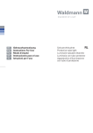
Typefaces
2
ABCDEFGHIJKLMNOPQRS
TUVWXYZ1234567890
Rotis Semi Sans Extra Bold
ABCDEFGHIJKLMNOPQRS
TUVWXYZ1234567890
Rotis Semi Sans Regular
ABCDEFGHIJKLMNOP
QRSTUVWXYZabcdefg
hijklmnopqrstuvwxyx
Sabon Regular
SM 218A
Rotis Semi Sans
Extra Bold
Rotis Semi Sans
Regular
Towson University
Interior Sign Program
Portnoy Levine Design Assoc.
231 E. Baltimore Street, 12th floor
Baltimore, MD 21202
410/234 8998
Scale:
3"=1'-0"
Date:
5/7/99
Sign colors
Color
palette
Background
color 1
Background
color 2
Background
color 1
PMS 195c
PMS Cool Gray
Black
3
Towson University
Interior Sign Program
Portnoy Levine Design Assoc.
231 E. Baltimore Street, 12th floor
Baltimore, MD 21202
410/234 8998
Scale:
2"=1'-0"
Date:
5/7/99
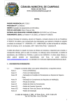
Sign type A
Main directory
Satin aluminum panel with logo
silkscreened in yellow and black
Heading 1-1/2" Sabon Bold, white
silkscreened
37-3/4" W x 27" H x 2-1/2" thick aluminum directory
sign with protective cover-holds 120 names painted
background color #1
120-1/2"x9" light gray acrylic inserts. Surface
silkscreened with black type.
Typeface:
Name or Department is 3/8" Sabon
Room number is 3/8" Rotis Extra Bold & Regular
4
Towson University
Interior Sign Program
Portnoy Levine Design Assoc.
231 E. Baltimore Street, 12th floor
Baltimore, MD 21202
410/234 8998
Scale:
3"=1'-0"
Date:
5/7/99
Sign type B
Secondary directory
5
Satin aluminum panel
1" Sabon Bold Black, silkscreened
Subsurface painted clear nonglare acrylic
Color #1
1" x 8" Background of Level Accent
Color
Typeface:
1/2" Rotis Extra Bold & Regular
white vinyl
1/2" and 3/8" Sabon white vinyl or
silkscreened
Towson University
Interior Sign Program
Portnoy Levine Design Assoc.
231 E. Baltimore Street, 12th floor
Baltimore, MD 21202
410/234 8998
Scale:
3"=1'-0"
Date:
5/7/99
Sign type C
Floor plan/directional
6
14 1/4" W x 20" H x 1" thick Poster Display
System with glass door, natural aluminum frame
6" x 12" digitally printed paper map fits behind
clear glass cover
5/8" Rotis Semi Sans white on Accent Color band
Surface silkscreened 12" x 18" paper
Color #1
Background of Arrow Accent Color
silkscreened
Typeface:
1" Rotis Semi Sans white, vinyl or silkscreened
Wheelchair symbol light gray
Towson University
Interior Sign Program
Portnoy Levine Design Assoc.
231 E. Baltimore Street, 12th floor
Baltimore, MD 21202
410/234 8998
Scale:
3"=1'-0"
Date:
5/7/99
Sign type D
Directional
7
Satin aluminum panel (.032)
1" Sabon Bold Black silkscreened
1/16" Subsurface painted clear non-glare
acrylic
Color #1
Background of Arrow Accent Color
(1/16" Acrylic arrow over 1/16" Acrylic)
Typeface:
1" Rotis Semi Sans white vinyl
Wheelchair symbol light gray
Towson University
Interior Sign Program
Portnoy Levine Design Assoc.
231 E. Baltimore Street, 12th floor
Baltimore, MD 21202
410/234 8998
Scale:
3"=1'-0"
Date:
5/7/99
Sign type E
Department ID
8
16" x 16" or 12" x 12"
1/16" Face acrylic
1/16" Subsurface painted clear nonglare acrylic
Color #1
Typeface:
3/8" Sabon Italic white vinyl or
silkscreened
1" Sabon Bold white vinyl
Satin aluminum panel (.032)
Towson University
Interior Sign Program
Portnoy Levine Design Assoc.
231 E. Baltimore Street, 12th floor
Baltimore, MD 21202
410/234 8998
Scale:
1"=2"
Date:
5/7/99
Sign type F
ADA room ID
1/16" Face acrylic
1/8" Acrylic subsurface painted clear,
non-glare
Color #1
Typeface: 3/4" Rotis Extra Bold & Regular
white vinyl
.040 LEXAN, clear coated intermediate
sheet
1.5" x 4" satin aluminum for raised
Helvetica lettering and Braille, with no
surface color
Satin Aluminum Notifier to hold 3"x5" card
NOTE: Base built up to be flush with upper
section photopolymer applied Braille
9
Towson University
Interior Sign Program
Portnoy Levine Design Assoc.
231 E. Baltimore Street, 12th floor
Baltimore, MD 21202
410/234 8998
Scale:
1"=2"
Date:
5/7/99
Sign type G
Office name ID
1/16" Face acrylic
1/8" Acrylic subsurface painted clear, non-glare
Color #1
Typeface: 3/4" Rotis Extra Bold & Regular
white vinyl
.040 LEXAN, clear coated intermediate sheet
3/8" Sabon name in white vinyl on removable
clear panel
1.5" x 4" satin aluminum for raised Helvetica
lettering and Braille, with no surface color
Satin Aluminum Notifier to hold 3"x5" card
NOTE: Base built up to be flush with upper
section photopolymer applied Braille
10
Towson University
Interior Sign Program
Portnoy Levine Design Assoc.
231 E. Baltimore Street, 12th floor
Baltimore, MD 21202
410/234 8998
Scale:
1"=2"
Date:
5/7/99
Sign type H
Door mounted ID
11
1/16" Face acrylic
1/8" Acrylic subsurface painted clear,
non-glare
Color #1
Typeface: 3/4" Rotis Extra Bold,
white vinyl
6" Symbol light gray vinyl
3" Wheelchair symbol light gray vinyl
1.5"x 8" satin aluminum for raised
Helvetica lettering and braille, with no
surface color
NOTE: Base built up to be flush with
upper section photopolymer applied
Braille
Towson University
Interior Sign Program
Portnoy Levine Design Assoc.
231 E. Baltimore Street, 12th floor
Baltimore, MD 21202
410/234 8998
Scale:
1"=2"
Date:
5/7/99
Sign type I
Projecting room ID
12
1/16" Face acrylic (two sides)
Color #1
2" Wheelchair symbol light gray
vinyl
7" Symbol light gray vinyl
Typeface: 3/4" Rotis Extra Bold &
Regular, white on 1-1/4"x 4" background of accent color.
8" x 8" Satin aluminum bracket
NOTE: Base built up to be flush
with upper section photopolymer
applied Braille
Towson University
Interior Sign Program
Portnoy Levine Design Assoc.
231 E. Baltimore Street, 12th floor
Baltimore, MD 21202
410/234 8998
Scale:
1"=2"
Date:
5/7/99
Sign type J
Floor ID
13
1/16" Face acrylic
1/8" Acrylic subsurface painted clear,
non glare
Color #1
Typeface: 3/4" Rotis Extra Bold &
Regular white vinyl
1.5"x 8" satin aluminum panel
NOTE: Base built up to be flush with
upper section photopolymer applied
Braille
Towson University
Interior Sign Program
Portnoy Levine Design Assoc.
231 E. Baltimore Street, 12th floor
Baltimore, MD 21202
410/234 8998
Scale:
1"=2"
Date:
5/7/99
Sign type K
Informational
1/16" Face acrylic
1/16" Acrylic subsurface painted clear, non
glare
Typeface: 3/8" Sabon white vinyl or
silkscreened
Color #2
Additional message can be added to same
plaque.
Typeface: 1/4" Sabon white
vinyl or silkscreened
14
Towson University
Interior Sign Program
Portnoy Levine Design Assoc.
231 E. Baltimore Street, 12th floor
Baltimore, MD 21202
410/234 8998
Scale:
1"=1"
Date:
5/7/99
Acceptable messages for sign type K
1
2
3
4
5
6
7
8
9
10
11
12
13
14
15
Authorized personnel only
Faculty only
Please keep door closed
Please keep door open
Open door slowly
Please knock before entering
Please do not lock this door
Please lock this door
Do not open without disengaging alarm
Be sure both latches are locked before closing the door
Research in progress
Please enter through room SM ___
Temperature controlled room
Safety glasses required in this area
Learn your colors-orange, red, rust
Sign type K
Messages
15
Towson University
Interior Sign Program
Portnoy Levine Design Assoc.
231 E. Baltimore Street, 12th floor
Baltimore, MD 21202
410/234 8998
Scale:
1"=2"
Date:
5/7/99
Sign type L
Informational
16
1/16" Face acrylic
1/16" Acrylic subsurface painted
clear, non glare, Color #2
Typeface: 3/8" Sabon white vinyl or
silkscreened subsurface
This plaque installs above Sign Type
H on door.
Towson University
Interior Sign Program
Portnoy Levine Design Assoc.
231 E. Baltimore Street, 12th floor
Baltimore, MD 21202
410/234 8998
Scale:
2"=1'-0"
Date:
5/7/99
Sign type M
College display
Heading 1" Sabon Italic, white
silkscreened
37-3/4" W x 27" H x 2-1/2" thick aluminum
case with cork or magnetic backing with
protective cover.
Painted Background Color #1
17
Towson University
Interior Sign Program
Portnoy Levine Design Assoc.
231 E. Baltimore Street, 12th floor
Baltimore, MD 21202
410/234 8998
Scale:
1"=2"
Date:
5/7/99
Sign type N
Regulatory
1/16" Surface silkscreened clear, non
glare acrylic, Color #2
1/16" Acrylic subsurface
3-1/2" no smoking symbol in PMS 195c
and black vinyl subsurface
18
Towson University
Interior Sign Program
Portnoy Levine Design Assoc.
231 E. Baltimore Street, 12th floor
Baltimore, MD 21202
410/234 8998
Scale:
1"=1"
Date:
5/7/99
Sign type O
Directory pylon
Aluminum sign box, 3" thick painted
Color #1
1" Sabon Bold Black
26" W x 20-1/4" H x 1" thick Poster
Display System with glass door, natural
aluminum frame
18" x 24" digitally printed paper map fits
behind clear glass cover. Map by
another vendor.
3" x 20 1/4" Accent Color painted band.
Typeface:
2" Rotis Extra Bold & Regular, silkscreen
1/2" Rotis on legend
Background of Arrow painted Accent
Color
Typeface:
1" Rotis Semi Sans white, silkscreen
Wheelchair symbol light gray
19
Towson University
Interior Sign Program
Portnoy Levine Design Assoc.
231 E. Baltimore Street, 12th floor
Baltimore, MD 21202
410/234 8998
Scale:
1"=2"
Date:
5/7/99
Sign type P
Cubicle nameplate
20
1/16" Face acrylic
EMPLOYEE NAME
1/16" Subsurface painted clear
non glare acrylic, Color #1
Typeface: centered, all uppercase,
3/8" Sabon white vinyl or silkscreened
subsurface
This mounts on the cubicle using
velcro.
Sign Type E
Portnoy Levine Design Assoc.
231 E. Baltimore Street, 12th floor
Baltimore, MD 21202
410/234 8998
Sign Type F
Sign Type K
Towson University
Interior Sign Program
Scale:
3/4"=1'-0"
Date:
5/7/99
Sign Type D
Corridor Signs
Sign Type I
Sign Type H
Sign Type L
Sign Type K
21
Sign Type O
Towson University
Interior Sign Program
Sign Type A
Portnoy Levine Design Assoc.
231 E. Baltimore Street, 12th floor
Baltimore, MD 21202
410/234 8998
Scale:
3/4"=1'-0"
Date:
5/7/99
Sign Type M
Main Lobby Signs
22
Towson University Design and Construction Standards
Introduction
OVERVIEW - These Design Guidelines and Construction Standards have been developed
to provide architects, engineers, contractors and Towson University in-house staff with
minimum guidelines for acceptable practices, methods and materials for design and
construction projects. They are a compilation of planning, design, construction and
maintenance expertise provided by university personnel.
These standards apply regardless of the value, type or location of the work. While most
sections refer to the A/E or Consultant, these standards are intended to apply to all parties
charged with the design, administration or construction of the proposed work.
A CHANGING DOCUMENT - These standards are considered a “living document” and
are subject to change. As the university develops new Standards, or changes existing
Standards, that information will be included into the current edition. Always consult
with the Towson University’s Facilities Management Department for the most current
edition.
FORMAT – These Standards are comprised of Design Standards, Construction Standards
and Appendices.
Design Standards – These Standards provide a comprehensive overview of the baseline
concepts and philosophies for design development.
Construction Standards – These standards provide minimum requirements for application
in each Section.
Appendices – While Appendices are integral to these Standards, they are referenced in the
Table of Contents and bound separately due to their size.
The Construction Standards have been written in standard CSI format to allow easy
reference by all to applicable sections. Not all sections are included in the document.
QUALITY OF STANDARDS – The quality of any one standard contained in this
document is based on precedent, reliability, serviceability and acceptable costs.
STANDARDS VS. SPECIFICATIONS - These Standards are not intended as
specifications, nor are they intended as a substitute for specifications developed by the
design professional. Where practices, methods or products are given, they should be
considered as a minimum requirement and expanded as required.
SUMMARY – Summaries are intended to give the reader conceptual insight regarding
past practices and existing and future preferences. Not all sections contain summaries.
QUALITY ASSURANCE – Where the reader finds reference to minimum qualifications
for a specific application, those qualifications should be included into the design
documents or complied with by the contractor.
PROPRIETARY PRODUCTS – Some products found in these Standards are noted as
being proprietary. Only those products are acceptable and may not be substituted with
proposed equal or other products.
I.
BASIC REQUIREMENTS
A.
B.
PURPOSE:
1.
Responsibility: Towson University’s Department Of Facilities
Management is responsible for all components of the built
environment on the campus - buildings, open spaces and
infrastructure.
2.
Building Goals: The Department of Facilities Management is
entrusted with providing Towson University with buildings which
incorporate a high degree of:
a.
Functional efficiency
b.
Innovative, but appropriate, design
c.
Contextual harmony with the site
d.
Appropriately selected materials and systems
e.
Health and safety characteristics
f.
Accessibility for the disabled
g.
Life-cycle value
3.
Applicability: These Architectural and Engineering Design
Standards have been compiled to establish general and, in some
cases, specific design policies as a guide to Towson University staff
and to consultant architects and engineers (A/E) for designing new
facilities, as well as the alteration or renovation of existing
structures. ANY DEVIATION FROM THESE STANDARDS
MUST BE SUBMITTED TO AND APPROVED IN WRITING BY
THE DIRECTOR OF ARCHITECTURE, ENGINEERING AND
CONSTRUCTION ON THE FORM INCLUDED IN THESE
STANDARDS.
4.
Supersedure: These Design Standards supplement the job-specific
Facility Program. Should the Facility Program and these Design
Standards conflict, these Design Standards shall supersede.
CAMPUS BACKGROUND:
1.
Towson University, the comprehensive metropolitan university of
the Baltimore region, is nationally recognized for its excellent
programs in the arts and sciences, business, communication, fine
arts, allied health sciences, and teacher education. The Physical
Plant of the university is comprised of forty-one buildings, situated
on 328 acres of rolling and partially wooded terrain.
2.
A daily campus population of nearly 21,000 persons, comprised of
3,944 staff and faculty and approximately 17,500 students, engage
in comprehensive higher education, and business and industry
outreach programs of a statewide scope.
66
C.
DESIGN PRINCIPLES:
1.
General: Towson University buildings, new and renovated, must
provide the functional, aesthetic, environmental, and safety needs of
the using-agency "client" and the requirements of governing
authorities, with a reasonable balance between initial cost and lifecycle value. Towson University is dedicated to improving the
quality of its campus and buildings through architectural, planning
and engineering services which must:
a.
b.
c.
d.
e.
D.
Ensure the highest degree of professionalism from the A/E
Team to develop and implement innovative and functional
design concepts, in harmony with the site environment, and
appropriate to the project needs.
Implement reliable procedures for controlling project
estimates, construction costs, life-cycle factors, and time
schedules.
Establish thorough quality-control coordination during all
phases of the A/E Scope of Services
Respond to governing codes and standards ensuring
environmental health and safety.
Assume that design concepts for repair, alterations and
renovations are executed with the same professional
consideration as that for new facilities.
CODES, STANDARDS, REVIEW AGENCIES:
1.
Applicability: Design and construction on Towson University
facility projects are subject to the following codes, standards, and
review agencies, to the extent noted:
a.
b.
Major projects are subject to compliance with the following
internal standards:
1.
Towson University Facilities Master Plan, and
Towson University Architectural and Landscape
Plan Design Guidelines – 1998
2.
Towson University General Conditions of the
Construction Contract, latest edition; Under the
General Conditions the entire project is guaranteed
for two (2) years. Therefore, unless a longer
guarantee time is required, it need not be addressed.
3.
Towson University Design Standards, latest edition
4.
DGS Procedure Manual for Professional Services,
Latest Edition, as amended
For all projects to be completed at Towson University; the
following apply as minimum:
1.
B.O.C.A. Basic Building Code, latest edition
2.
The B.O.C.A. Basic/National Mechanical Code,
latest edition
67
3.
4.
5.
6.
7.
Maryland State Fire Prevention Code, incorporating
the NFPA 101, Life Safety Code (latest edition) and
its referenced standards
The National Electrical Code, latest edition
Maryland Occupational Safety & Health
Administration (MOSHA)
Maryland Safety Code for Elevators, Dumbwaiters,
Escalators and Moving Walks, latest edition
Department of Licensing and Regulation
Bureau of Labor and Industry
501 Saint Paul Place
Baltimore, Maryland 21202
State of Maryland Fire Prevention Code
Office of the State Fire Marshal
106 Old Court Rd. - Suite 300
Pikesville, Maryland 21208-0892
8.
9.
10.
11.
c.
Specifications for Making Buildings Accessible to
and Usable by Physically Handicapped People, ANSI
A 117.1 (1986)
Americans with Disabilities Act (ADA),
Public Law 101-336 Dept. of Justice, 1991
ASHRAE Handbook and Standard 90-75: Standard
for Energy Conservation in Building Design
Annotated Code of Maryland, Sections 4-802 and 4808, relative to "Procurement-Solar Power"
For projects which contain animal facilities:
American Association for the Accreditation of
Laboratory Animal Care (AAALAC)
9650 Rockville Pike
Bethesda, Maryland 20814
d.
For projects which require excavation and/or storm water
management:
Maryland Department of The Environment
2500 Broening Highway
Baltimore, Maryland 21224
e.
For all Maryland state-funded capital construction projects:
The State Architectural Review Board
Department of General Services
301 W. Preston Street
Baltimore, Maryland 21201
68
f.
For projects which impact Baltimore County Streets:
Department of Traffic Engineering
Baltimore County
Towson, Maryland 21204
g.
For projects utilizing Baltimore Gas and Electric Co. direct
service:
BG&E Middle Department Inspection Agency
3610 Milford Mill Road
Baltimore, Maryland 21208
E.
INFORMATION FURNISHED TO THE A/E:
1.
Information furnished to the A/E: Towson University’s OFM will
make available, at the request of the A/E, any existing utility plans,
topographic plats, and "Record Drawings" construction documents
(drawings and specifications) on file. No assurances, however, are
given that these record drawings are accurate or complete. See
attached Supplemental General Conditions.
69
70
PART II
TU CAD STANDARDS
I.
TOWSON UNIVERSITY CAD STANDARDS
Design Development and 100% complete contract drawings shall be prepared and furnished
on brand-name quality, ZIP disks or on CD in Autodesk's AutoCAD, Version 2000 in
accordance with the following Towson University CAD Standards:
A.
GENERAL
1.
RELATED DOCUMENTS
The General Provisions of the Contract including General and Supplementary
Conditions, Specification Sections and Contract Documents of Division 1,
and other related sections apply to work in this section. Consult them for
further instructions and be governed by their requirements.
2.
WORK INCLUDED
a.
3.
Work included in this section:
1.
Computer Aided Drawing standards for construction (CAD)
2.
All required documentation for CAD
3.
Required submittal media and format
SECTION INTENT
Towson University is actively pursuing a program of computerized
construction related documents and Computer Integrated Facilities
Management (CIFM). In general terms, this section describes the requirements
for CAD related drawings, the required accompanying documentation, and
the form and format of the electronic data.
The intent of these standards is two-fold: one, to permit the efficiency of the
consultant’s internal drawing development methods by not imposing overly
ambitious CAD standards and two, to provide a set of documents that are
consistent with the needs of Towson University for both Facilities
Management and future construction.
B.
BEGINNING A PROJECT
1.
START-UP INFORMATION
a.
The following information shall be provided by Towson University ‘s
Facilities Management Department at the request of the consultant in
both electronic and/or hard copy format. It is the consultant’s
responsibility to include this information on all CAD files and large
documentation.
1. Key Plan – Shall be either a building footprint or a site plan with
the project area noted. Key plans shown shall be for the purpose of
locating sheet specific information within the project area.
2. Current Room Numbers – Only the most current room numbers
shall be used on project documentation. These numbers may be
obtained from the floor plan drawings maintained by the CAD
office.
70
b.
C.
3. TUFacilities.dwg – Drawing to be used for layer and dimstyle
information. TU Facilities Management can provide standard
24”x36” or 30”x42” border sheets.
TU Facilities Management will not research and/or compile the
necessary drawings needed for a specific project. It is the responsibility
of the project manager or consultant to come in and choose the
appropriate information and request copies from Towson University.
FORMAT
1.
CAD FILES
All drawings shall be submitted in AutoCAD (Autodesk Inc.) .DWG format
and is compatible with AutoCAD Architectural Desktop. Towson University
shall not accept any drawings in the Drawing Interchange Format (DXF). If
any drawing translators are used prior to submittal the results of such
translations shall be 100% complete. It is the responsibility of the consultant
to crosscheck translated drawings for errors and/or omissions.
2.
MEDIA
a.
b.
c.
d.
D.
All electronic drawing files shall be submitted on either 3 ½” floppy
diskettes 1.44 MB High Density format, IBM compatible 100 MB
iomega zip disk, or CD-R (Recordable Compact Disc). WinZip (An
archive utility for Windows) may be used for file compression.
All submitted electronic media shall be clearly labeled with consultant
name, project title and date of submittal. Labels shall be firmly
attached to diskette/CD.
Naming extensions used shall be as follows:
1.
.DWG – AutoCAD drawing file; Drawing filenames shall
contain the sheet number they represent (i.e. A3-1.DWG)
2.
.DOC – Documentation files providing general descriptions
such as layer lists
Record drawing sheets shall be plotted onto reproducible media.
These sheets will become part of the Towson University archives.
CONSTRUCTION DOCUMENTATION REQUIREMENTS
1.
GENERAL DESCRIPTION
a.
b.
c.
Towson University will be using the construction documents on CAD
for three major purposes:
1.
Long-term document archival
2.
Reference
3.
Provide architectural backgrounds for future work
The intent of this part is to establish minimal standards for CAD
development and specific requirements for drawing documentation.
The Towson University Facilities Management Department will not
provide CAD files or copies of design documents to sub-consultants or
contractors working on the same or another related project. This
information is the property of the design firm until the project is
71
complete and record documents are submitted to Towson University
Facilities Management.
2.
DRAWING ORGANIZATION
a.
b.
c.
3.
DRAWING DOCUMENTATION
a.
b.
E.
All drawing documents shall be 100% complete on CAD.
The font files used in submitted CAD documentation should be
restricted to only standard unmodified AutoCAD and Microsoft
Windows font files.
All entities drawn in CAD must be at full scale.
LAYERS – The consultant shall submit a complete list of all layers
used on a drawing file with the following information:
1.
The layer name as it appears on the drawing file
2.
Expanded description of layer name
3.
The default color and line type of layer
LINE WEIGHT – The consultant shall provide a .ctb file (pen style
table) for pen assignments.
SUBMITTAL REQUIREMENTS
1.
SUBMITTAL REQUIREMENTS
a.
REVIEW – Consultant is required to submit a review set to the Project
Manager at all design phases. Room numbers will be assigned by
Towson University Facilities Management, when appropriate, and
shall be used on all drawings throughout all design stages. Demolition
plans shall include existing room numbers for reference.
b.
100% CONSTRUCTION (Bid Set)
1.
CAD files for all hardcopies
2.
Complete set of hardcopies
3.
Specification books
c.
RECORD DRAWINGS (“as-builts”)
1.
CAD files – Before submitting as-built CAD files to the
Towson University project manager, any external references
(xref) must be bound and all appropriate script files shall be
run so that when the CAD files is opened, it shows a true visual
representation of the corresponding hard copy. The “PURGE
ALL” command shall be performed prior to submittal to
remove unused elements and reduce drawing file size.
2.
Record drawing sheets – Shall be plotted onto reproducible
media. Manual corrections on the as-built reproducibles not
reflected in the CAD drawings are not acceptable.
3.
Redlined construction documents
4.
Updated Specification books
5.
Drawings to be furnished shall be appropriate to properly
convey the required work.
72
6.
7.
8.
9.
Operation and Maintenance Manuals, as required by the
project contract
Plat drawings shall be related to the Baltimore County
Coordinate grid system and utilize land surveyor’s units and
angles.
All elevations shall be stated as Baltimore County mean low
tide datum.
All details and sections shall be cross-referenced indicating
location of details and sections, as well as where they are
taken.
d.
SPECIFICATIONS
1.
All specifications shall follow the C.S.I. format.
e.
BIDDING REQUIREMENTS
1.
A/E will receive procurement specifications from Towson
University's Procurement Department for inclusion in the
Project Manual.
2.
A/E will receive Towson University's Standard General
Conditions of Construction Contract from Towson
University's Procurement Department for inclusion in the
Project Manual.
3.
00800 - Amendments to General Conditions: Such
amendments are to be reviewed by Towson University's
Facilities Management Department and Towson University's
Procurement Department prior to inclusion in the Project
Manual.
4.
00830 - Prevailing Wage: A/E will receive Prevailing Wage
Rates/Statements from Towson University's Procurement
Department when applicable, for inclusion in the Project
Manual.
73
BITUMINOUS ROOFING
SECTION 07510
PART 1
1.0
GENERAL
Summary
A.
1.1
Towson University has several different types of roof systems used throughout
the campus. These roofs range from four ply built up, modified bitumen, foam
and single ply systems. The majority of roofs are four ply built up with stone
ballast. For the most part, Towson University prefers the four-ply built-up
ballasted system. However, different building types may dictate different roof
systems. For this reason, the consultant should consult AEC prior to the
Schematic Design Phase to clarify the type of roof proposed.
Roof Types
A.
The following roofing system types are acceptable to Towson University for
applications to low-slope (min. 1/4": 1' - 0") roofs.
B.
It is the consultant’s responsibility to select the roofing system most
appropriate for the building. The consultant shall provide the necessary
drawings, details, and specifications to provide Towson University with a
sound, watertight, long lasting roofing system.
C.
References: National Roofing Contractors Association
D.
Acceptable membrane roofing systems:
1.
2.
3.
4.
5.
4-ply, built-up, aggregate type II ballasted, asphalt bitumen roofing
system (1AGA or NAGA)
4-ply, built-up, aggregate type II ballasted modified roofing system
2-ply, built-up, with modified bitumen granulated cap sheet, unballasted
Interlocking standing seam 24-gauge (minimum) commercially pure
aluminum coated steel (aluminized type II) roof
Unballasted, fully adhered fastened, single-ply EPDM roofing system
with a (minimum) sheet thickness of 0.045 inches
E.
Aggregate for ballasted systems shall be nominally 3/8" diameter minimum.
Meeting ASTM D-1863, and embedded in a flood coat of hot asphalt.
F.
Walkway systems shall be installed to and around all mechanical
equipment. Typical walkway systems are lightweight concrete pads.
Granulated modified bitumen sheet is not preferred but may be acceptable
BITUMINOUS ROOFING
07510 - 1
SECTION 07510
BITUMINOUS ROOFING
under certain conditions such as when built-up modified systems are used.
Consult AEC for acceptable materials.
G.
Indicate on the drawings the following information as required relating to
membrane roofing systems.
1.
Roof plan for each area of roofing, clearly indicating extent of each
type roofing, including slopes, including insulation and vapor
retarders (if any)
2.
Detailed pattern lay out of taper insulation showing numerical
sequence of installation.
3.
Required thicknesses and taper of insulation
4.
Taping of substrate or insulation joints, where required
5.
Flashing, stripping, sealants, cants, tapered edge trips nailers, reglets, etc.
at terminations of roofing; Show nailers where required
6.
Areas of extra aggregate surfacing course, if any waterways,
walkways, etc. include both locations and dimensions.
7.
Details of roof drains and other waterways and drainage facilities
8.
Locations and dimensions of walkways (if any), and how they are
supported
9.
Color of surfacing
10. Areas of special UL rating, if any (other than rating specified). UL:
Class A fire hazard (UL790) FM: Roof Assembly Classification, meet
wind uplift requirements for I-90 windstorm
NFPA: Current Edition adopted by State Fire Marshall’s Office
11. Locations and large-scale details for sheet metal roofing accessories,
and type metal if several specified
12. Locations and large-scale details of roof expansion joints, curbs,
penetrations, equipment supports, etc. (Use NRCA details as guide)
1.2
Warranties
A.
Guarantee by the manufacturer shall include but not be limited to roofing,
insulation, base flashing system and shall be for a term of 20 years with no
BITUMINOUS ROOFING
07510 - 2
SECTION 07510
BITUMINOUS ROOFING
dollar limit (NDL) and no penalty sum.
B.
PART 2
2.0
PRODUCTS
Fascia, Copings, Metal Edges
A.
All exposed metal such as fascia, metal edges and copings shall be .040 ga.,
minimum with Kynar paint finish.
B.
Color selections of metals to be coordinated with FM, AEC Department.
C.
All metals to be installed utilizing continuous cleats. Continuous cleats are
to be one gauge heavier metal than fascia, metal edges and coping
specifications.
PART 3
3.0
INSTALLATION
Metals
A.
3.1
Do not fabricate and install fascia metal wider than 6”. “Oil canning”,
dents, buckles, etc. are not acceptable.
Bleed Out
A.
3.2
Contractors guarantee shall be five (5) years.
The contractor will minimize bleed out of bitumen where the roof is
normally exposed to view. Where bleed out of bitumen is required,
broadcast granular materials matching the granular roof system into the
bitumen.
Flood Test
A.
At the completion of all roof work, the contractor shall perform a flood test
in the presence of the owner. Areas of the roof that exceed manufacturers
tolerances for standing water will immediately be removed and corrected
prior to final payment.
END OF SECTION
BITUMINOUS ROOFING
07510 - 3
METAL DOORS & FRAMES
SECTION 08100
PART 1 GENERAL
1.0
Summary
A.
1.1
1.2
This section pertains to interior and exterior metal entrance doors and frames to be
provided for all contracts unless specified otherwise in these standards. While
these standards are minimum, the consultant is encouraged to maintain "heavy
duty" for all specified products.
Labeled Doors and Frames
A.
Specify or note where required, UL labels with the appropriate fire resistance and
temperature rise ratings for the class of opening indicated.
B.
Verify all openings and requirements with the State Fire Marshall during design.
ADA Compliance
A.
Consider ADA requirements when specifying frames and doors including:
1.
2.
3.
Pull resistance requirements including negative air spaces
Latch side clearances
Appropriate accessible hardware
PART 2 MATERIALS – MINIMUM REQUIREMENTS
2.0
Metal Doors
A.
Typically, metal doors are full flush without lites. This should not be interpreted
as being the only solution for design. Where the consultant desires metal doors
with lites or other face types coordinate with the owner for approval. Metal doors
shall have the following minimal characteristics.
1.
Interior Doors
a. Level 2 and Physical Performance Level B (Heavy Duty)
b. Cold rolled steel face sheets
c. Seamless
d. Door silencers
e. Shop primed/Alkyd field finished
2.
Exterior Doors
a. Level 3 and Physical Performance Level A (Extra Heavy Duty)
b. Metallic coated steel sheet or galvanized steel sheet (consult owner)
c. Seamless
METAL DOORS AND FRAMES
08100 - 1
SECTION 08100
METAL DOORS AND FRAMES
d. Weather-stripped
e. Shop primed/Alkyd field finished
2.1
2.2
Metal Frames
A.
Materials
1.
For Level 3 doors– 14 gauge
2.
For Level 2 doors– 16 gauge
B.
Construction
1.
Welded frames for all new construction with ground smooth
surfaces
2.
Mitered knock down type permitted for replacement when walls are not
removed.
3.
Shop primed with rust inhibiting primer
4.
Minimum Reinforcement:
a. 11 ga. steel hinge reinforcement plates for 4 ½” hinges.
b. 14 ga. strike reinforcement plate
c. 12 ga. closer reinforcement plate
5.
12 ga. Closer reinforcement
6.
6 ga. Hinge reinforcement
7.
14 ga. Lock reinforcement
8.
Preformed rigid polystyrene core
9.
Factory cleaned and primed, field finished
Galvanized Option: For exterior doors and frames, and elsewhere required, specify ASTM
A60 hot dipped galvanized coating at 0.6 oz., mill treated for proper adhesion.
PART 3
3.0
EXECUTION
Installation
A.
The door/frame contractor is fully responsible for checking the prepared opening
prior to setting the frame. Openings that are not plumb, square or have irregularities
should not have frames set. Frames that are set in unacceptable openings will be
removed by the door/frame contractor and replaced, without cost to the owner, after
the opening is corrected.
END OF SECTION
METAL DOORS AND FRAMES
08100 - 2
FLUSH WOOD DOORS
SECTION 08211
PART 1 GENERAL
1.0
Summary
A.
1.1
Quality Assurance
A.
1.2
1.3
A.
Specify or note where required, UL Labels with the appropriate fire resistance and
temperature rise ratings for the class of opening indicated.
B.
Verify all openings and requirements with the State Fire Marshall during design.
ADA Compliance
PART 2
Consider ADA requirements when specifying:
1.
Pull resistance requirements including negative air spaces
2.
Latch side clearances
3.
Appropriate accessible hardware
MATERIALS – MINIMUM REQUIREMENTS
Selection of Doors
A.
2.1
Work specified under this section shall be accomplished by qualified, skilled
tradesmen who have continuously and successfully performed the required tasks
for a minimum of five (5) years.
Labeled Doors
A.
2.0
This section pertains to flush wood doors to be provided, where said doors are
required, for all new and alteration work. While many classrooms and office
suites use solid core wood doors, some buildings were designed using horizontal
grade plastic laminate. Alterations in those buildings allow for doors “in kind.”
All new construction will use finished solid core, hardwood veneer doors as
outlined below. Alteration and renovations would allow for matching existing
conditions in academic buildings.
Coordinate with AEC to determine the type of each door and the finish required
for each application.
Veneers
A.
Specify only solid core wood doors with hardwood veneers. Doors are to be top
quality only.
FLUSH WOOD DOORS
08211 - 1
SECTION 08211
B.
FLUSH WOOD DOORS
Hardwood veneers are typically "stain grade", Birch.
Where the program calls for oak veneer, use only top quality materials. For doors
slated to receive paint finish, "paint grade" veneers are acceptable.
C. Crossband: Hardwood veneer, nominal 1/16" thick
2.2
Dimensional Data
A.
2.3
Finishes
A.
2.4
3.1
See Section 09900 Painting for Finish requirements
Frames: See Section 08100 Metal Doors and Frames
PART 3
3.0
Typical doors are 6’8" x 3’0" x 1¾". However, where existing adjacent doors
exist, match those doors in face dimension.
EXECUTION
Protection/Storage of Wood Doors
A.
The contractor shall be fully responsible for the protection and storage of wood
doors after delivery. Specify that doors are to be maintained in door racks until
needed for use.
B.
Maintain new doors in a stable environmental condition until needed for use. Do
not allow doors to be stored in a humid environment.
C.
All wood doors shall be immediately sealed after cutting of tops and bottoms.
Installation
A.
The door/frame contractor is fully responsible for checking the prepared opening
prior to setting the frame. Openings that are not plumb, square or have
irregularities should not have frames set. Frames that are set in unacceptable
openings will be removed by the door/frame contractor and replaced, without cost
to the owner, after the opening is corrected.
END OF SECTION
FLUSH WOOD DOORS
08211 - 2
ALUMINUM ENTRANCE AND STOREFRONTS
SECTION 08410
PART 1 GENERAL
1.0
Summary
A.
1.1
Quality Assurance
A.
1.2
Work specified under this section shall be accomplished by a qualified vendor,
whose skilled tradesmen who have continuously and successfully performed
projects of equal size and complexity for a minimum of five (5) years.
Storefront Configuration
A.
PART 2
2.0
This section provides minimum construction standards for all aluminum/storefront
entrances. These entrances must be specified as "best quality" and "heavy duty"
for all components and construction.
Coordinate with the owner for storefront door configuration. The preferred
configuration provides all doors hinged from the same direction. However, the
purpose for this is to accommodate the specified hardware. The consultant still
has the flexibility of utilizing other configurations if the specified hardware can be
accommodated.
MATERIALS – MINIMUM REQUIREMENTS
System Requirements
A.
Doors
1.
Manufacturers standard 1-¾” thick glazed door with minimum 0.125 inch
thick extruded tubular rail and stile members.
2.
Stiles: Typically, doors are designed as medium stile. Wide stile doors are
acceptable where existing, adjacent wide stile doors exist. This selection is
due to high volume of student traffic and abuse. Narrow stile doors are
not acceptable except where approved by FM.
3.
Finish: The trend at Towson University is to use bronze duronodic
door finishes. This does not prevent the consultant from specifying a clear
anodized door, especially in renovation or addition work where existing
door finishes are established. Verify the desired finish with AEC.
4.
Weather Stripping: Manufacturer’s standard replaceable weather-stripping
as follows:
ALUMINUM ENTRANCE AND STOREFRONTS
08410-1
SECTION 08410
ALUMINUM ENTRANCE AND STOREFRONTS
a. Compression weather stripping: Molded neoprene complying with
ASTM D 2000 requirements or molded PVC complying with ASTM D
2287 requirements.
b. Sliding weather stripping: wool, polypropylene, or nylon woven pile
with nylon fabric or aluminum strip backing with AAMA 701
requirements.
c. Weather sweeps: manufacturers standard weather sweep for application
to exterior door bottoms and with concealed fasteners on mounting
strips.
5.
Fasteners and accessories: manufacturers standard corrosion resistant, non
bleeding fasteners and accessories compatible with adjacent materials.
6.
Finishes: Class I, anodic finish: AA-M12C22A42/A44 (mechanical finish:
non specular as fabricated; chemical finish: etched, medium matte; anodic
coating: Architectural Class I, integrally colored or electrolytically
deposited color coating 0.018mm or thicker complying with AAMA 606.1
or AAMA 608.1.
7.
Construction
a. Mechanically fastened, SIGMA deep penetration welded corners.
b. Integral weatherstrip system as supplied by the manufacturer, including
integral sweeps as required.
8.
Hardware
a. Except as noted below, refer to section 08710 for this information.
b. Hinges: use only heavy-duty Roton Continuous door hinges. Type and
offset of hinges must be adapted to the opening and approved by AEC
prior to submission.
c. Exit Devices: Von Duprin 99 Series- Rim
d. Locks: All lock cylinders as determined under Section 08710 must
be accompanied by a BEST construction core.
e. Pulls: (reserved)
f. Push Plates: (reserved)
2.1
Manufacturer: Following are acceptable manufacturers of aluminum storefront:
A. Kawneer
B. VistaWall
C. YKK AP America, Inc.
ALUMINUM ENTRANCE AND STOREFRONTS
08410-2
SECTION 08410
ALUMINUM ENTRANCE AND STOREFRONTS
D. EFCO Corporation
PART 3
EXECUTION
3.0 Building Security
A. The contractor shall at all times provide for a secure entrance to the facility under
construction. Where existing storefront has been removed, reinstall new work
including locks within one (1) workday. When new systems cannot be installed in the
same day, provide adequate means of securing the facility as approved by the
university’s project manager.
3.1
Construction Safety
A.
The storefront contractor is solely responsible for providing adequate
protection to pedestrians during installation of storefront materials. Do not allow
pedestrians to enter the building through the construction area. Barricade area
directly in front of the installation area and provide directional signage to alternate
entrances.
END OF SECTION
ALUMINUM ENTRANCE AND STOREFRONTS
08410-3
FINISH HARDWARE
SECTION 08710
PART 1
1.0
Summary
A.
1.1
1.3
Attached is a Specification Section 08710 available for the A/E to use directly in
the proposed documents.
Quality Assurance
A.
Work specified under this section shall be accomplished by qualified, skilled
tradesmen who have continuously and successfully performed the required tasks
for a minimum of five (5) years.
B.
Experience for tradesmen stated above must include the types, models and
functions of the specified products.
Finish Hardware
A.
1.4
Towson University, through its in-house lock shop, is required to maintain, repair
and interchange many locks, cylinders, exit devices and assorted other finish
hardware on an ongoing basis. For this reason, it is imperative to maximize the
value and economics of a standardized hardware system. As described in the
attached "Spec Section", all materials specified are proprietary with no
consideration for substitutions.
Attached Specification Section
A.
1.2
GENERAL
This section specifies those items collectively referred to as "Finish Hardware" or
"Architectural Finish Hardware". Section encompasses those items of hardware
essential to operation, control, and weatherstripping of swinging and sliding doors
as normally used throughout a building, namely wood and hollow metal doors. At
present, this portion of these standards will focus on hardware for swinging doors,
interior and exterior, including storefront.
Finish Hardware Schedule
A.
Provide a "Finish Hardware Schedule" listing each of the proposed contents of
each hardware group:
1.
2.
3.
4.
FINISH HARDWARE
Show the quantity of each type of item proposed to be supplied within each
Hardware Group
Show the dimensions, when pertinent, and the manufacturer’s catalog
number
Show the finish of each item
Show the manufacturer’s name by a suitable legend
08710-1
DRAFT COPY
SECTION 08710
FINISH HARDWARE
PART 1 - GENERAL
1.0
SUMMARY
A.
Section includes: Finish hardware except as otherwise specified or specifically
omitted herein
B.
Related sections:
1.
2.
3.
1.1
SUBSTITUTIONS & SUBMITTALS
A.
1.2
Section 06200 - Finish Carpentry: Installation of finish hardware
Section 08100 - Standard Steel Doors and Frames
Section 08211 - Wood Doors
Only products specified under Part II of this Section are acceptable. Make no
substitutions.
QUALITY ASSURANCE
A.
B.
Qualifications:
1.
Obtain each kind of hardware (latch and locksets, exit devices, hinges and
closers) from only one manufacturer, although several may be indicated as
offering products complying with requirements.
2.
Hardware supplier to be a qualified, factory authorized, direct contract
hardware distributor of the products to be furnished. In addition, the
supplier to have in their regular employment an certified Architectural
Hardware Consultant (AHC) who will be made available at reasonable
times to consult with the owner, architect, and/or contractor regarding any
matters affecting the finish hardware on this project.
Fire-rated openings: Provide hardware for fire-rated openings in compliance with
NFPA Standard No. 80. This requirement takes precedence over other
requirements for such hardware. Provide only such hardware which has been
tested and listed by UL for the type and size of door required, and complies with
the requirements of the door and the door frame labels. Latching hardware, door
closers, ball bearing hinges, and seals are required whether or not listed in the
Hardware schedule.
FINISH HARDWARE
08710-2
SECTION 08710
1.
1.3
1.4
1.5
FINISH HARDWARE
Where panic exit devices are required on fire-rated doors, provide
supplementary marking on door UL label on exit device indicating "Fire
Exit Hardware."
DELIVERY, STORAGE AND HANDLING
A.
Acceptance at the site: Individually package each unit of finish hardware complete
with proper fastening and appurtenances, clearly marked on the outside to indicate
contents and specific locations in the work.
B.
Deliver packaged hardware items at the times and to the locations (shop or field)
for installation, as directed by the contractor.
PROJECT CONDITIONS
A.
Coordination: Coordinate hardware with other work. Furnish hardware items of
proper design for use on doors and frames of the thickness, profile, swing security
and similar requirements indicated, as necessary for the proper installation and
function, regardless of omissions or conflicts in the information on the contract
documents.
B.
Upon request, check the shop drawings for doors and entrances to confirm that
adequate provisions will be made for the proper installation of hardware.
WARRANTY
A.
Provide written two-year guarantee from hardware manufacture, as well as
hardware supplier for the following items:
1.
2.
3.
4.
5.
Locksets
Exit devices
Closers
Electronic closers
All other hardware
Warranty shall begin with substantial completion of the project, not installation.
PART 2 - PRODUCTS
2.0
Hinges
A.
Interior
1. Manufacturer: Hager, Lawrence, Stanley
2. Finish: Match adjacent hardware for retrofit or match locksets for new work
3. Specifics: Hinges to be extra heavy weight for high frequency openings or
doors 36" and over in width. All hinge open widths shall be minimum, but of
sufficient size to permit door to swing 180. Furnish hinges with three knuckles
and concealed bearing. Furnish 3 hinges per leaf to 7 foot 6 inch height; Add
one for each additional 30 inches in height or fraction thereof
FINISH HARDWARE
08710-3
SECTION 08710
B.
2.1
FINISH HARDWARE
Exterior
1. Manufacturer: Roton
2. Type: Heavy-duty continuous aluminum, offset for minimum 180 degrees
3. Finish: Consult owner
Locksets
A.
Manufacturer: Cylindrical – Best Locking
Mortise – Best Locking preferred, or Russwin/Corbin
B.
Cylindrical
1. Model: Best 93K7 15D
2. Performance: Extra-heavy-duty cylindrical with Best 7-pin interchangeable
core; Lockset and cores to be of the same manufacturer to maintain complete
lockset warranty; Locks to have solid shank with no opening for access to
keyed lever keeper; Lock chassis must be through-bolted (outside of the lock
chassis prep to prevent rotation of chassis after installation; Lock manufacturer
shall provide a three-year warranty, in writing, to the owner, along with three
copies of the lock service manual; Strikes shall be 16-gauge curved brass,
bronze or stainless steel with a 1" deep box construction and have sufficient
length to clear trim and protect clothing
a. Lock Series and Design: Best 93K7 15D at existing construction
b. Cores/Cylinders: Best 7-Pin with "Premium" Keyway to match existing
system
C.
Mortise: Locks and Latches, series 35H at NEW CONSTRUCTION, shall be
heavy-duty with hinged, anti-friction, 3/4 inch throw latch bolt with anti-friction
piece made of self lubricating stainless steel; Functions and design as indicated on
the hardware groups; Deadbolt functions shall be 1-inch projection made of
hardened stainless steel, both deadbolt and latch bolt are to extend into the case a
minimum of 3/8 inch when fully extended; Furnish locksets and latchets with
sufficient curved strike lip to protect door trim; Provide locksets with 7-pin Best
interchangeable core cylinders; All mortise cylinders shall have a concealed internal
setscrew for securing the cylinder to the lockset; The internal set screw will be
accessible only by removing the core from the cylinder body; locksets and latchets
are to have self-aligning, thru-bolted trim; Auxiliary dead latch to be made of onepiece stainless steel, permanently lubricated; Lever handles must be of forged or
cast brass, bronze or stainless steel construction; Spindle to be such that if forced,
it will twist first, then break, thus preventing forced entry; Levers to be operated
with a roller-bearing spindle hub mechanism.
1. Lock Series and Design: Best 35H7 15H (Rose trim) at new construction
2. Lock series and Design: Best 15J Trim (EscutcheonTrim) at existing
construction
3. Cores/Cylinders: Best 7-Pin with "Premium" keyway to match existing system
D.
Exit Devices: Furnish all sets at wood doors with sex bolts unless otherwise
specified in Wood Door Section/ Hardware blocking. Trim of exit devices to match
trim of locksets. Provide rim devices at single doors. At pairs of doors with low
visibility provide two rim devices with key removable mullion. At doors with high
FINISH HARDWARE
08710-4
SECTION 08710
FINISH HARDWARE
visibility, provide concealed vertical rod devices. Depending on location, at
exterior openings provide two surface vertical rod devices or two rim devices with
key removable mullions.
1. Exit Device Series: Von Duprin 99 Series
E.
Surface Door Closers: Full rack and pinion type with removable non-ferrous cover.
Provide sex bolts at all wood doors unless otherwise specified in Wood Door
Section/Hardware blocking. Place closers inside building, stairs, and rooms. Closers
shall be non-handed, non-sized and adjustable.
1.
2.
3.
4.
5.
6.
7.
8.
2.2
2.3
Closer Series: LCN 4041 or 1461
Provide multi-size 1 through 6 at all doors rated or not
Exterior and high frequency openings to receive 4041 Series
Interior and low frequency openings to receive 1461 Series
All closers shall be cast iron
Flush transom offset brackets shall be used where parallel arm closers are listed
for doors with fixed panels over
Drop brackets are required at narrow head rails
Set exterior doors closers to have 8.5 lbs maximum pressure to open, interior
non-rated at 5 lbs, rated openings at 12 lbs. and meet all ADA requirements
F.
Kickplates: Provide with four beveled edges, 10 inches high by width less 2 inches
on single doors and 1 inch on pairs of doors unless otherwise specified. Furnish
Type "A" screws to match finish.
G.
Seals: All seals shall be finished to match adjacent frame color. Seals shall be
furnished as listed in schedule. Material shall be UL listed for labeled openings.
H.
Screws: All exposed screws shall be Phillips head
I.
Silencers: Furnish silencers on all interior frames, 3 for single doors, 2 for pairs
Omit where any type of seals occur
FINISH
A.
As selected by architect and/or owner
1. Protection plates, push, pulls shall be selected by architect
B.
Spray door closers to match other hardware, unless otherwise noted
C.
Aluminum items shall be finished to match predominant adjacent material. Seals to
coordinate with frame color
KEYING REQUIREMENTS
A.
Provide Best brass construction cores and keys during the construction period.
Black plastic construction cores will not be permitted. Construction control and
operating keys and core shall not be part of the owner's permanent Best keying
system or furnished on the same keyway (or key section) as the owner's permanent
FINISH HARDWARE
08710-5
SECTION 08710
FINISH HARDWARE
Best keying system. Permanent Best cores and keys (prepared according to the
accepted keying schedule) will be furnished to the owner (by the local Best factory
representative) prior to occupancy.
B.
All cylinders shall be Best 7-pin, interchangeable core "Premium" keyway to match
existing key system.
C.
Permanent Best keys and cores shall be stamped with the applicable key mark for
identification. These visual key control marks or codes will not include the actual
key cuts. Permanent keys will also be stamped "Do Not Duplicate."
D.
Grand Masterkeys, Masterkeys and other security keys shall be transmitted to the
Owner by Registered Mail, return receipt requested.
E.
Furnish keys in the following quantities:
0 each Grand Masterkeys and Control key to be furnished by Towson University
4 each Masterkeys per set
4 each Change keys each keyed core
9 each construction Masterkeys
1 each construction Control keys
F.
The owner, or the owner's agent, will install permanent cores and return the
construction cores to the Best Access Systems factory representative. All
construction cores and keys remain the property of Best Access Systems.
G.
Keying schedule: Submit three copies of separate detailed schedule indicating
clearly how the owner's final instructions on keying of locks has been fulfilled.
PART 3 - EXECUTION
3.0
HARDWARE LOCATIONS
A.
Hinges:
1.
2.
3.
4.
Bottom Hinge: 10 inches from door bottom to bottom of hinge
Top Hinge: 5 inches from door top to top of hinge
Center Hinge: Center between top and bottom hinge
Extra Hinge: 6 inches from bottom of top hinge to top of extra hinge
B.
Lock: 38 inches from finished floor to center of lever or knob
C.
Push Bar: 44 inches from bottom of door to center of bar
D.
Push Plate: 44 inches from bottom of door to center of plate
E.
Pull Plate: 42 inches from bottom of door to center of pull
F.
Exit Device: 39-13/16 inches from finished floor to center of pad
G.
Deadlock Strike: 44 inches from floor, centered
FINISH HARDWARE
08710-6
SECTION 08710
3.1
3.2
3.3
FINISH HARDWARE
INSTALLATION
A.
Hardware is to be installed by experienced finish hardware installers only.
B.
Install finish hardware in accordance with the approved hardware schedule, the
manufacturers’ printed instructions and in accordance with recommended
locations for architectural hardware for standard steel doors and frames, by the
Door and Hardware Institute. Prefit hardware before finish is applied; remove and
reinstall after finish is complete and dry. Install and adjust hardware so that parts
operate smoothly, close tightly and do not rattle.
C.
Installation shall conform to local governing agency security ordinance.
ADJUSTING
A.
Adjust and check each operating item of hardware and each door to ensure proper
operation or function of every unit. Replace units which cannot be adjusted to
operate freely and smoothly.
B.
Inspection: Hardware supplier shall inspect all hardware furnished within 10 days
of contractor's request and include with his guarantee, a statement that this has
been accomplished. Inspector or contractor shall sign off the hardware as being
complete and correctly installed and adjusted. Further corrections of defective
material shall be the responsibility of his representative.
SCHEDULE OF FINISH HARDWARE
A.
Legend of listed manufacturers:
HA
Hager
BE
Best
VD
Von Duprin
LC
LCN
NG
National Guard
RO
Rockwood
B.
The items listed in the following "Schedule of Finish Hardware" shall conform
throughout to the requirements of the foregoing specification. The last column of
letters in the Hardware Schedule refers to the manufacturer abbreviation listed
above.
C.
The door schedule on the drawings indicates which Hardware Set is used with
door.
END OF SECTION
FINISH HARDWARE
08710-7
GYPSUM BOARD ASSEMBLIES
SECTION 09255
PART 1 GENERAL
1.0
Summary
A.
This section identifies standard framing and gypsum wallboard products to be used
at Towson University. Products specified for framing are for conventional
applications and do not include materials required for unusual or other specific
purposes such as those dictated as a result of structural restrictions.
The consultant should be sure to include in the documents appropriate language
concerning gypboard finishes. Too often, the contractor does not have qualified
personnel to perform the required tasks to give the proper finishes. Many times,
vertical gypboard installations prove to show undulations when natural light is
cast on it. When these conditions exist, paint selections should be restricted due to
reflectability. The consultant should identify these areas of concern when
determining class of finish.
1.1
Project Conditions
A.
1.2
The consultant should confirm with the owner what the HVAC conditions will be
during construction. Where conditions dictate that the contractor provide
supplemental or interim climate control to maintain the integrity of the product, or
as demanded by the manufacturer, include such language in the specifications. In
addition, verify and coordinate with the owner the availability and use of existing
utilities for temporary climate control equipment.
Interior Wall Design
A.
All walls should be constructed from floor to the deck above. Floor to ceiling is
not a preferred application and should be avoided. When new walls are required
in existing construction, and a plenum ceiling exists, attempt to construct walls full
height with transfer grills sized for HVAC requirements. When this method is not
a practical approach, consult AEC for remedy.
B.
Walls shall only be constructed of steel framing unless otherwise approved by
AEC.
C.
Walls should have full sound blankets the entire height of the wall.
D.
Acoustical sealant to be applied at all perimeter joints.
GYPSUM BOARD ASSEMBLIES
09255-1
SECTION 09255
PART 2
2.0
ASTM C 645
Thickness: 20 ga.
Depth: 3-5/8"
Spacing: 16" o.c.
Steel Rigid Furring Channels
A.
B.
2.2
MATERIALS – MINIMUM REQUIREMENTS
Steel Framing for Walls and Partitions
A.
B.
C.
D.
2.1
GYPSUM BOARD ASSEMBLIES
ASTM C 645
Hat shaped with depth and thickness as follows:
1.
Thickness: 0.0329 inch or higher
2.
Depth: 7/8"
Gypsum Board Products
A.
Standard Installations – ASTM C 36 and as follows:
1.
2.
Dimensions: 1/2"x 48”x longest lengths available to minimize butt joints.
Fire Resistant - Rated assemblies:
a. Type "X"
b. Thickness: 5/8"
2.3
Sound Attenuation Blankets
A.
PART 3
3.0
Unfaced mineral fiber blanket comply with ASTM C 665 for Type I (without
membrane facing)
EXECUTION
The following are minimum installation standards for this section:
A.
Steel Partition Framing
1.
2.
3.
B.
Provide bracing at lock locations
Provide double studs at all doorframe locations
Provide backer boards at all interior corners, vertically and horizontally
Metal Trim Corners
1.
Plastic and vinyl trim is not acceptable.
2.
Reveal type "J" beads, with exposed return flange, requiring no finishing
compound (such as USG #400) are not acceptable in any location that
remains visible upon completion of work. Specify, in lieu thereof, products
similar to USG #200 or #800 series trim.
GYPSUM BOARD ASSEMBLIES
09255-2
SECTION 09255
3.
C.
D.
GYPSUM BOARD ASSEMBLIES
All corner beads are to be mechanically fastened.
Gypsum Board
1.
Install gypsum board only in longest sections possible, with tapered edges
horizontal.
2.
Single piece vertical applications of gypsum board are acceptable in wall
spaces under twelve (12’) linear feet and within closed offices.
3.
All gypsum board to be glued and mechanically fastened.
4.
Neatly cut around wall outlets, switches and other devices that penetrate
the face of the panel. Do not over cut and fill. Over cut panels will be
rejected.
5.
Sanding of finish gypsum board shall be done in a controlled environment.
Where work is not remote and is adjacent to existing occupied spaces, the
contractor shall thoroughly seal all doors, windows, cracks and HVAC
systems to ensure no dust migration. The contractor is responsible for
coordination of HVAC outages with FM during sanding operation.
6.
No painting will be allowed until a dust free environment has been
established. Gypboard face must be thoroughly cleaned prior to painting.
Obtain the owners approval to complete the required painting tasks after
the prime coat has been applied.
Finishes
1.
All walls shall be Level 4 finish.
END OF SECTION
GYPSUM BOARD ASSEMBLIES
09255-3
CERAMIC TILE
SECTION 09310
PART 1 GENERAL
1.0
Summary
A.
1.1
Quality Assurance
A.
1.2
This section describes the minimum requirements for typical applications of
ceramic tile. The university’s preference is to have floor tile that will allow a
contrasting dark grout. Wall tile is typically lighter with matching grout color.
Work specified under this section shall be accomplished by qualified, skilled
tradesmen who have continuously and successfully performed the required tasks
for a minimum of five (5) years. In addition, the individual must have a thorough
knowledge of acceptable substrate conditions and acceptable remedy for failed
systems.
Consultant Subsurface Investigations
A.
It is the responsibility of the consultant to thoroughly investigate existing substrate
conditions prior to design. Where there is conflict between the university’s
drawings and a historical record of substrate conditions, field verify by selective
demolition. In some circumstances, the university’s in-house trades can accomplish
minor work to verify substrate conditions.
B.
Where existing substrate conditions are suspect in part or whole, include removal
and replacement in the design. Patching is only acceptable where adjacent
substrate is structurally sound and capable of maintaining a monolithic system
when complete.
PART 2
MATERIALS – MINIMUM REQUIREMENTS
2.0
Only ceramic tile of the "Best Quality" shall be specified for use.
2.1
Ceramic tile colors are typically a neutral shade that would be adaptable to a variety of
adjacent wall finish colors. Coordinate color selections with the owner early in the design
phase.
2.2
Ceramic floor tile
A.
Standard ceramic floor tile size is 2" x 2". Darker grouts are preferred.
B.
Ceramic floor tile shall be "non-slip" surface only, where wet conditions exist.
Provide manufacturers literature regarding coefficient and friction.
CERAMIC TILE
09310-1
SECTION 09310
C.
2.3
2.4
CERAMIC TILE
As a part of the ceramic floor tile system, provide marble thresholds at entrances.
Thresholds to have proper tapers to conform with ADA Standards. Install widest
thresholds for minimal rise.
Ceramic Wall Tile
A.
Standard ceramic wall tile size is 4" x 4".
B.
Provide ceramic cove base, bull nose corners and Wainscot caps at appropriate
locations.
Grout
A.
PART 3
Latex – Portland Cement Grout
1.
Unsanded grout for joints 1/8” and less
2.
Sanded grout for joints 1/8” and larger
EXECUTION
3.0
Ceramic floor tile is typically placed in standard sheet supplied pattern. Alternative
patterns are to be submitted to AEC office for approval during the Schematic Design
Phase. Typical joints are 1/16”.
3.1
Wall tile is typically placed in stacked pattern.
END OF SECTION
CERAMIC TILE
09310 - 2
ACOUSTICAL CEILINGS
SECTION 09510
PART 1
1.0
Summary
A.
1.1
The consultant should confirm with the owner what the anticipated HVAC
conditions would be during construction. Where conditions dictate that the
contractor provide supplemental or interim climate control for tile installation,
include such language in the specifications. In addition, verify and coordinate with
the owner the use of existing utilities for temporary climate control equipment.
Fire Rated Ceilings
A.
PART 2
2.0
Historically, the university has found that certain activities and programs within a
building may affect the integrity of the new ceiling system. Buildings that allow
dances or other large crowd activities may cause exceptional deflections in the
support structure above the new ceiling. New ceilings in areas of excessive
movement should be properly designed to provide adequate and long life support.
Coordinate with AEC for the programmatic use of each facility.
Project Conditions
A.
1.3
Most ceilings found at Towson University are the acoustical type specified in this
section. For this reason, it is imperative that all new or renovated areas receive the
type specified to maintain consistency. To maintain a higher level of sound
attenuation and to have mechanical systems access, the consultant should refrain
from specifying gypboard ceilings except in specific areas such as bathroom
ceilings.
Structural Investigations
A.
1.2
GENERAL
It is the consultant’s responsibility to determine if the products identified herein are
suitable and acceptable for the required fire rating. Where a conflict exists,
coordinate with AEC for determination of an acceptable product.
MATERIALS – MINIMUM REQUIREMENTS
Tile and Grid
A.
All Spaces
1.
2.
3.
4.
Acceptable Tile No. 1 (for grid type no. 1)
2’x 2’, USG - Eclipse Climaplus SLT
Acceptable Tile No. 2
2’x 2’ Armstrong Cirrus – Beveled Tegular Edge # 584
Grid Type No. 1: USG Standard - 15/16" white
Grid Type No. 2: Armstrong Prelude XL 15/16” Reveal, white
ACOUSTICAL CEILINGS
09510 - 1
SECTION 09510
2.1
Extra Stock
A.
PART 3
3.0
ACOUSTICAL CEILINGS
Provide 2% of the total tile amount installed as extra stock. Materials are to be
delivered and stored in a location designated by the AEC office.
EXECUTION
The following are minimum installation standards for this section:
A.
Ceilings Tiles
1.
2.
3.
4.
B.
Typically, equally spaced tiles with perimeter tile dimensions that are
constant are preferred.
Tiles shall be neatly "cut in" at perimeters so that the cuts are not visible.
Provide drop in cuts at perimeters and all cut tiles.
Tiles damaged during installation must be replaced, not repaired (as with
touch up paint).
Grid
1.
Ceiling systems over 4,000 sq. ft. (assuming a single wall exceeds 60 lin. ft.)
are to be installed utilizing a laser line technology.
2.
Minimal length for power activated fasteners for suspension wires is 1" or
better as required by the structural engineer.
3.
The preferred method for attachment of suspension systems utilizes the
existing structural system above ("I" Beams, etc.), where possible.
4.
No exposed ″pop-rivets″ on grid are permitted without approval from the
university’s project manager.
END OF SECTION
ACOUSTICAL CEILINGS
09510 - 2
RESILIENT FLOORING
SECTION 09650
PART 1 GENERAL
1.0
1.1
Summary
A.
Resilient flooring and carpet are the soft flooring products most used on
campus. Sheet materials are not acceptable and vinyl composition tile
(VCT) has been the standard. While the consultant is free to design spaces
with non-standardized patterns, including field and border patterns, the
manufacturer and types listed below should be considered for all classroom
and non-executive office spaces. All products included in the design must
meet the minimum criteria listed below.
B.
Where new resilient flooring meets existing ceramic coved wall base,
indicate method of terminations on the drawing with large-scale details.
C.
Provide specific written methodology and drawings for vinyl cove base
radius attachment. See Part 3 of this section.
Quality Assurance
A.
1.2
1.3
Work specified under this section shall be accomplished by qualified, skilled
tradesmen who have continuously and successfully performed the required
tasks for a minimum of five (5) years.
Existing Asbestos Containing Materials
A.
Some buildings at Towson University may have asbestos containing
materials. In regards to this section, asbestos tile and mastic may exist
throughout campus. This should be considered when preparing documents
for new resilient flooring installation. The university maintains records of
known existing ACM locations. The consultant should confirm those
locations with the AEC office. Where tile or mastic is suspected, the
material must be tested for ACM by the university’s Environmental Health
and Safety Office.
B.
See Demolition under this section
Climate Control
A.
The contractor is responsible for providing an installation environment in
accordance with the manufacturers recommendations. Materials that are
RESILIENT FLOORING
09650-1
SECTION 09650
RESILIENT FLOORING
installed in an environment not acceptable to the manufacturer will be
rejected and reinstalled at no cost to the owner.
PART 2
2.0
Extra Stock
A.
2.1
MATERIALS – MINIMUM REQUIREMENTS
Specify not less than 5% for fewer than 100 sq. ft. and 3% for over 100 sq.
ft. for each type, color, pattern and size installed.
Vinyl composition Tile (VCT)
A.
Standard size and gauge for VCT is 12" x 12" x 1/8"
B.
Manufacturer/Type:
1.
2.
2.2
Sub flooring/Underlayments
A.
2.3
Specify underlayments over existing wood floors or sub floors as 1/4”
smooth surfaced plywood. Masonite is not an acceptable underlayment.
Vinyl Cove Base
A.
PART 3
3.0
Armstrong, Standard Excelon
Armstrong, Premium Excelon
Vinyl Cove Base: 4" high, except where pre-existing conditions dictate a
higher cove, coved over resilient flooring, toeless at carpet flooring. Colors
selection from manufacturers standard range of colors.
EXECUTION
Demolition
A.
Contractor is responsible for removing all materials from campus as a result
of demolition, including sub-flooring materials, except for materials
containing asbestos.
B.
Where asbestos containing materials are found to exist, coordinate with the
owner for removal. All removals shall be accomplished by the university
through the Environmental Health and Safety office. Include coordination
in the documents to include persons responsible for removal, dates of
removal and interface with the contractor.
RESILIENT FLOORING
09650-2
SECTION 09650
3.1
3.2
RESILIENT FLOORING
Tile Installation
A.
Preparation: Provide only sound substrate for VCT installation. Flash patch
or solid fill voids and other irregularities prior to placement of
underlayment. Where underlayment is installed, use a nailing pattern into
sound substrate acceptable to the manufacturer, 6” o.c. minimum.
B.
Typically, VCT is installed with the grain constant in one direction. Where
the consultant desires a deviation from the normal, coordinate with the
AEC office for acceptable alternative patterns.
Vinyl Cove Base
A.
Proper installation of vinyl cove base is critical to a complete and acceptable
flooring project. Use only best methods for attachment.
1. Do not use nails or other fasteners for temporary or permanent
attachment.
2. Do not apply vinyl cove base over unsound substrate.
3. Provide temporary bracing as required until mastic is fully set and
support vinyl cove base in its intended position.
4. Apply mastic in neat uniform beads using a notched spreader as
recommended by the manufacturer. Do not allow mastic to “bleedout.” Use a hand roller to roll out the base, working in the direction of
the next joint.
5. For projects requiring in excess of 100 lin. ft. use only continuous roll
materials.
6. For outside corners: Mark the base where the corner will be positioned.
Shave a strip approximately ¼” wide and ¼ the thickness from the back
of the base where the corner is marked. Use a solvent based contact
adhesive 4” in each direction away from the corner to provide
maximum adhesion.
END OF SECTION
RESILIENT FLOORING
09650-3
CARPET
SECTION 09680
PART 1
1.0
General
A.
1.1
1.2
For many years, the university has installed a wide range of carpet with different
pile weights and styles throughout campus. In recent past, 26 oz. broadloom has
been the standard. For the most part, this applies to classrooms, offices, labs and
certain specialty areas. Areas such as executive offices and high traffic areas may
require heavier carpet with higher quality pile or the use of carpet tiles. The
carpets required for specialty areas and executive offices are not provided here, but
instead should be coordinated and approved for each application with FM.
Quality Assurance
A.
Work specified under this section shall be accomplished by qualified, skilled
tradesmen who have continuously and successfully performed commercial carpet
installation for a minimum of five (5) years.
B.
Qualifications of Installers: All work shall be done by installation firms specializing
in commercial carpet installation. It is recommended that, whenever possible, the
firm shall be a member of the Floor Covering Installation Contractors Association
(FCICA) or certified by the Floor Covering Installation Board (FCIB).
C.
Carpet manufacturer shall certify by register and roll numbers that carpet shipped
for this project complies with all requirements of this section subject to normal
manufacturing tolerances. Only materials with the same dye lot number will be
accepted.
D.
As a condition of bidding, the university may require a room mock up of all
potential qualified carpets. The sample will be approximately 12’ x 12’ and may
be required prior to selection of the successful carpet supplier.
Grade Selection
A.
1.3
GENERAL
In general, carpet grades selected will be different for each application. Although a
specific grade is listed under Part 2, products of this section, grade selection will be
made at the discretion of the director of AEC.
Seaming Plan
A.
CARPET
Towson University requires a seaming plan for all carpet to be installed. No carpet
shall be installed without approval of that plan by the project manager in charge.
09680 - 1
SECTION 09680
1.4
Carpet Tile
A.
PART 2
2.0
2.1
CARPET
Carpet tile is not typically a standard product. However, there are applications
where carpet tile is practical, especially in high volume or food service areas and
may be requested by the end user, or recommended by the A/E. Proposed
installation of carpet tiles should be presented to the owner designer at the SD
Phase for consideration. Where carpet tile is initiated by either the owner or A/E,
the tile shall be approved by the university.
MATERIALS – MINIMUM REQUIREMENTS
Source Quality Control
A.
Manufacturer shall be an integrated mill (tufting, dyeing and backing in house)
with a formal Quality Improvement Process or equivalent quality initiative in
operation. Manufacturer shall provide verification when requested.
B.
Manufacturer shall be a member of the Carpet and Rug Institute (CRI) and
specified product shall comply with the CRI’s Indoor air Quality Testing Program
(Green label).
C.
Testing
1.
Carpet supplier shall furnish test results by an independent testing
laboratory made for each of the performance criteria listed herein.
2.
The owner, at his option, may request additional tests from an independent
test lab at his own expense on any portion of furnished fabric for
conformance with his criteria.
3.
Tests, if ordered, shall be at the expense of the owner if material is in
compliance with this section. If material is not in compliance with this
section, the carpet supplier shall bear testing costs.
General
A.
Following is minimum performance data required for a typical application at
Towson University. This criterion is intended for use by design consultants as a
guide in making recommendations to the university. Upgrades or exceptions may
be required for specific applications. Coordinate requirement with the owner.
1. CLASSROOMS, FACULTY/STAFF LOCATIONS
a.
b.
c.
d.
e.
f.
g.
h.
CARPET
Pile Fiber
Yarn Construction
Dye Method
Manufacturing Process
Pile Surface
Gauge
Tufted Stitches Per Inch
Tufted Yarn Weight
100% 6.6 Branded Nylon
Bulked Continuous Filament
Solution or Piece as required
Tufted
Dense Loop
1/10 or better
9 minimum
26 oz./SY min typical
09680 - 2
SECTION 09680
CARPET
i.
j.
k.
l.
m.
PART 3
3.0
3.1
Special Treatment
Backing System
Static Generation
Width
Flammability Rating
a. Flooring Radiant Panel
b. NBS Aminco Smoke
n.
Lightfastness
o.
Crockfastness
p.
Atmospheric Fading
q.
Colors
Fluorochemical
Life Span or approved equal
3.0 kv or less (AATCC-134)
12 ft.
Class I (ASTM E 648)
450 or less (ASTM
E 662 Flaming Mode)
Rating of not less than 3
on International Grey Scale
after 300 SFU’s
(AATCC Test Method 16E0
Minimum stain rating on
International Grey Scale
of not less than 4 wet and
dry (AATCC Test Method 165)
Burned Gas shall not be less than 3
on International Grey Scale
after two cycles on each test
As selected from manufacturer’s
standard color palette
EXECUTION
Restoration
A.
Any damage done to paint, walls, woodwork, floors, and/or similar finishes as a
result of this work, shall be the responsibility of the carpet contractor. Include
language regarding inspection of surfaces prior to carpet installation.
B.
Required repairs shall be made by the proper trade contracted on the work for this
project, who shall make the necessary repairs and shall be paid by the carpet
subcontractor for the repair work.
Extra Stock
A.
Upon completion of installation, deliver a minimum of 5% of each type, color, and
pattern of carpet, exclusive of material required to properly complete installation
or of usable pieces described previously in this section. Where carpet tile is
installed, provide 8% of each type.
B.
Furnish accessory components as required
C.
Furnish replacement materials from the same production runs as installed materials
D.
Package replacement materials with protective covering with identifying labels
E.
Store extra stock where directed by the owner.
END OF SECTION
CARPET
09680 - 3
PAINTING
SECTION 09900
PART 1
1.0
GENERAL
Summary
A.
1.1
The university, through its in-house paint shop, has established paint standards as
listed below, for each application. For other applications not provided in this
section, coordinate with AEC for approved products.
Project Conditions
A.
1.2
The consultant should confirm with the owner what the HVAC conditions will be
during construction. Where conditions dictate that the contractor provide
supplemental or interim climate control, include such language in the
specifications. In addition, verify and coordinate with the owner the use of
existing utilities for temporary climate control equipment.
Finishes
A.
1.3
The consultant is responsible for determining the right paint for the right
application (i.e. ferrous metals, gypboard assemblies). Areas that receive large
amounts of sunlight should be given special consideration to minimize
irregularities in the wall finish.
Low Odor Paint
A.
1.2
Where painting is required in an occupied building, use only low odor paint as
specified below.
Warranty
A.
PART 2
2.0
2.1
All paint materials and workmanship are subject to the Towson University
standard 2-year (24 months) period from the date of final acceptance as noted in
Towson University Standard General Conditions.
MATERIALS – MINIMUM REQUIREMENTS
Following this section is a complete Towson University paint schedule. This schedule does
not prohibit the use of other paint types required for a specific use by the consultant.
However, finishes other than those shown here must be approved in advance of design by
the director of Architecture, Engineering and Construction.
Colors
A.
PAINTING
A list of 25 standard colors are on file in the Facilities Management department.
These standard colors are generally the preferred colors used throughout the campus.
09900 - 1
SECTION 09900
PAINTING
This does not exclude the use of other colors as may be appropriate for a specific
project.
2.2
Materials
A.
See attached paint schedule for each paint application
B.
Low Odor Paint – Duron Genesis odor free paint
PART 3
3.0
3.1
3.2
EXECUTION
Controlled Climate Environment
A.
All painting, regardless of type, shall be accomplished in a controlled climate
environment. Where work is not remote and is adjacent to existing occupied
spaces, the contractor shall thoroughly seal all doors, windows, cracks and HVAC
systems during the painting process.
B.
All areas slated to be painted shall be ventilated to the outside using mechanical
means (i.e. fans, ventilators, exhausters.) The contractor shall submit, in detail,
plans for properly ventilating the space to AEC as part of the submission
requirements of the contract.
Finish
A.
All walls and ceilings, new or existing shall receive at least two finish coats of the
specified paint.
B.
Apply paint using brushes and rollers of high quality grade and as appropriate for
the task. DO NOT THIN PAINT. Lap marks, holidays, sags, brush marks, runs
and other imperfections in the paint application will not be accepted.
Protection
A.
The paint contractor is responsible for protection of all adjacent surfaces. The
contractor shall at all times protect those surfaces with approved materials.
B.
Protection of horizontal surfaces must utilize materials that will not cause tripping
hazards. When providing floor protection in areas being used by the public,
temporarily tape drop cloths and paper sheet to the flooring.
C.
When working in areas of electronic equipment, especially computers, make
provisions for complete protection including shutting down or relocation of
equipment if possible.
D.
Provide adequate “Wet Paint” signs. When possible, provide “Caution” taped
areas to avoid interference with the paint operation.
PAINTING
09900 - 2
SECTION 09900
3.3
PAINTING
Clean Up
A.
The paint contractor is responsible for a complete and thorough clean up of the
areas and items painted. Over paint, splatter and spills will be completely removed
prior to inspection of the work.
END OF SECTION
PAINTING
09900 - 3
PLASTIC TOILET PARTITIONS/SOLID SURFACE PRODUCTS
SECTION 10170
PART 1
1.0
1.1
Summary
A.
Until recently, the university has specified metal and phenolic materials for toilet
partition systems. These systems have proven to be somewhat vandal-resistant,
but not vandal-proof. The new systems specified under this section have to date
stood up to the punishment incurred in the university’s academic facilities. For this
reason, only the products listed will be acceptable.
B.
Only solid surface products similar to those specified here are to be specified for
use as lavatory, vanity top and other adjacent sanitary tops.
Submittals
A.
1.2
Specify required submittals under this section to include:
1.
Shop drawings in sufficient detail to show fabrication, installation,
anchorage and interface of the work of this section with the work of
adjacent trades.
2.
Manufacturers written installation procedures.
3.
HDP toilet partition product samples of each color or texture required.
Samples shall be as supplied by the manufacture, 4" x 4".
ADA Compliance
A.
1.3
GENERAL
All toilet room design shall be accomplished utilizing the most current and
stringent of ADA regulations and rules. Where structural members cannot be
changed to accommodate acceptable compliance design, notify the owner to
discuss acceptable alternative methods.
Support Systems
A.
Where horizontal solid surface products such as counters and lavatory tops are to
be constructed, use like materials for support in accordance with the
manufacturers recommended designs or constructed using HDP products to match
adjacent toilet partitions. The consultant should design for worse case abuse when
considering structural supports for these materials.
PLASTIC TOILET PARTITIONS/ SOLID SURFACE PROD.
10170-1
SECTION 10170
PART 2
2.0
MATERIALS – MINIMUM REQUIREMENTS
Toilet Partitions
A.
Where all new construction is proposed, or where total renovations of a toilet
room or other space that required toilet partitions exists, install only the following
products.
1.
High Density Polyethylene (HDPE) panels
2.
Technical data requirements are based on Santana HDPE products and
components.
A.
Associated components and fasteners not specified by the manufacturers shall be of
the best quality.
B.
Urinal screens, shower compartments, dressing compartments
1.
2.1
A.
Lavatories, vanity and countertops are to be one-piece monolithic design with
integral bowls and splashes in locations as required by the architect.
B.
Solid surface products to be Corian, as manufactured by Dupont, or equal.
Installation procedures shall be based on manufacturers written recommended
installation procedures.
Renovation Work
A.
3.2
EXECUTION
Installations
A.
3.1
Where urinal screens, shower compartments or dressing compartments are
required, specify products of the same type as the toilet partitions.
Solid Surface Materials
PART 3
3.0
PLASTIC TOILET PARTITIONS/SOLID SURFACE PROD.
When renovating existing toilet rooms is slated, include repair of existing floor and
wall surfaces in the documents. Repairs include any wall and floor surface affected
by the work and shall match the existing surface in color, texture and size.
Clean Up
A.
The contractor is responsible for thoroughly cleaning all components of the
installed products and any adjacent surfaces affected by the installation. Do not
leave pencil marks.
END OF SECTION
PLASTIC TOILET PARTITIONS/ SOLID SURFACE PROD.
10170-2
SIGNAGE
SECTION 10426
PART 1
1.0
GENERAL
Summary
A.
The Towson University campus signage standards have been established to ensure
a consistent level of identification which is familiar and readily recognizable in all
buildings, and to ensure a quality which is appropriate for the institutions' image.
As such, the standards utilized are thought to be neither too elaborate nor modish;
insubstantial or inadequate. Consistency is to be maintained throughout all
facilities and is to be modified in part only as necessary for coordination with local
conditions, as approved by FM.
B.
Signage systems are customarily installed as part of a capital improvement or
facilities renewal project. A new or renovated building will be fitted with a new
signage system, and renovation of a single floor or a large department may require
a new signage system. However, a single suite or room renovation requiring new
signage is provided with signs which match the remainder of the building.
Changes on directories and individual signs match the system within the building.
Signage systems design shall be in accordance with the Towson University Interior
Sign Program, the individual building program, and include building identification,
room identification, directory and way-finding systems. Certain building programs
may have requirements for additional exterior signage including ADA required
signage. If the design program is nonspecific to these requirements, then the
requirements shall be developed in conjunction with the Department of Facilities
Management. The proposed color of interior signs and directories shall be
consistent with these standards and shall be submitted for approval with the
interior design materials and colors submittal. Variations of the standards shall be
developed with the Facilities Planning department.
1.1
Towson University Brand Mark Standards
A.
1.2
Towson University’s "Brand Mark Standards" are available for review through
FM. The sign design should be developed in stages coordinating with FM and the
Facilities Planning department.
Interior and Exterior Sign Standards
A.
SIGNAGE
Following are Towson University’s Interior and Exterior Sign standards.
10426 - 1
TOILET ROOM ACCESSORIES
SECTION 10800
PART 1
1.0
Summary
A.
1.1
Towson University has generally standardized toilet room accessories campus
wide. This has been accomplished by use of a single source housekeeping vendor
under contract with the university. Through the Housekeeping Contract, the
vendor supplies certain toilet room accessories as listed in Part 2. Products of this
section. The consultant/contractor should be familiar with the products listed and
properly plan for their inclusion with the project design. The contractor may find
economy in purchasing these products through the university’s vendor. Contact
the AEC representative for contact.
Related Sections
A.
1.2
GENERAL
All drawings and general provisions of the contract including General and
Supplemental General Conditions, Division 1 and other documents sections
required for interface with this section.
Submittals
A.
PART 2
Specify required submittals under this section to include:
1.
Shop drawings in sufficient detail to show fabrication, installation,
anchorage and interface of the work of this section with the work of
adjacent trades
2.
Manufacturers written installation procedures
3.
Provide manufacturers written product data showing compliance with the
requirements specified under this section
MATERIALS – MINIMUM REQUIREMENTS
2.0
Following are products standard for use under this section. Some products listed may be
proprietary and are indicated with a bullet. Other products listed are shown as
performance criteria only.
2.1
Owner Supplied Accessories
The following products will be supplied by the university unless otherwise directed by the
Department of Facilities Management. The products listed are proprietary and shall be
included in the documents, but noted as "owner supplied". All installations are to be
accomplished by the contractor. The consultant should consider these proprietary
products when associating other products not supplied by the owner.
TOILET ROOM ACCESSORIES
10800 - 1
SECTION 10800
•
1. Paper Towel Dispenser
a.
b.
•
Manufacturer: GOJO
Model: Dermapro
4. Toiler Seat Cover Dispenser
a.
b.
2.2
Manufacturer: Kimberly Clark
Model: JRT Jr. Escort In Sight or
Model: JRT Jr. In Sight Twin Jumbo
3. Wall Mounted Soap Dispenser
a.
b.
•
Manufacturer: Fort James
Model: Generation II
2. Toilet Paper Dispenser
a.
b.
•
TOILET ROOM ACCESSORIES
Manufacturer: Kimberly Clark
Model: Health Gards Toilet Seat Cover Dispenser
Other Accessories
A.
Grab Bars
1.
2.
3.
4.
B.
Material: 1 1/2" diameter, satin texture stainless steel
Construction: Concealed plates with no exposed fasteners
Length: As required by ADA
Weight requirements and configuration as dictated by ADA
Soap Dish (When Required)
1. Material: Heavy gage stainless steel
2. Construction: Seamless
3. Mounting: Recessed
C.
Combination Feminine Napkin and Tampon Vendor
1.
2.
3.
4.
D.
Material: 18-gauge stainless steel
Construction: welded construction, concealed piano hinge; two tumbler locks
Capacity: 30 feminine napkins, 27 tampons
Dispensing mechanisms: 25c
Paper Towel Disposal
1. Material: 22-gauge stainless steel
2. Construction: Same as "a" above
3. Capacity: 5.75 gal. minimum
Note: Combination units with "a" or "b" above are acceptable
TOILET ROOM ACCESSORIES
10800 - 2
SECTION 10800
E.
TOILET ROOM ACCESSORIES
Feminine Napkins Disposal
1. Material: Stainless steel
2. Construction: Welded, self-closing doors secured with full-length stainless steel
piano hinges; tumbler locks
3. Mounting: Recessed
F.
Towel/Robe Hook
1. Material: Heavy gauge stainless steel
2. Construction: Concealed wall plate, no exposed fasteners
G.
Shelf
1. Material: Heavy gauge stainless steel, projects 8 inches from wall
2. Construction: Rolled formed edges; concealed mounting
3. Mounting: Surface
H.
Framed Mirror
1. Material: ¼ inch clear polished plate mirror with 20-gauge galvanized steel
back and stainless steel retainer angle
2. Mounting: Concealed wall hanger and theft resistant locking screws
3. Size: 18 inches wide x 24 inches high
I.
Shower Rod and Hooks
1. Material: 18-gauge, 1-1/4 inch diameter, stainless steel tubing
2. Mounting: 2-1/2 inch square flange
J.
Shower Curtain
1. Material: 8 mil white vinyl, opaque with heat sealed grommets
2. Size: Variable
3. Mildew resistant
PART 3
3.0
EXECUTION
Installations
A.
All installations are to be accomplished by the contractor, regardless of the source
of supply.
B.
Installations to be in accordance with manufacturers written instructions.
END OF SECTION
TOILET ROOM ACCESSORIES
10800 - 3
1-800-893-3665
Monumental Shelters
The original Brasco shelter design, the Monumental, stands today as a monument to
the strength and durability found in all Brasco International shelters. The Monumental
Series projects an image of strength through the use of 4" x 4" aluminum framing
members as columns and beams. The Monumental can accommodate a wide variety of
decorative trims and roof designs.
The 6' x 12' with center windscreen has a dome roof, waste
receptacle and schedule holder
.
BUS SHELTERS
SECTION 13046
PART 1
1.0
GENERAL
Summary
A.
PART 2
Where shelters of the type described herein are part of the program, verify the
preferred locations and vehicle/pedestrian approach with the university
representatives prior to final location determination.
MATERIALS – MINIMUM REQUIREMENTS
2.0
Use only the products/manufacturer as described in this section.
2.1
Bus Shelters
A.
Manufacturer: Brasco International
B.
Features:
•
•
•
•
•
•
C.
2.2
Black anodized aluminum structures – three sided
1/4" Clear tempered safety glass
Barrel vault style roof, black with fascia and integral gutter
Two schedule holders
Full-length aluminum bench with backrest
4' fluorescent light fixture with CW ballast and photocell
Standard Size: 6’ x 9’
For further information on these products, go to http://www.brasco.com/
END OF SECTION
SHELTERS AND BOOTHS
013046 - 1
SECURITY ACCESS AND SURVEILLANCE
SECTION 13700
PART 1 GENERAL
1.0
Summary: Towson University requires all new building construction, including additions
and renovations, to have security access systems for perimeter entrances.
All new buildings considered for surveillance systems will be identified during the
Programming Phase of design.
Towson University is always in the process of identifying the requirements and needs of
interfaced proximity cards, specifically for use by people with disabilities. Consult Towson
University for current requirements when designing security access systems.
1.1
Quality Assurance
A.
1.2
The products and manufacturers specified below are proprietary. Use only
the products and associated components from the manufacturer shown. Where
components of other manufacturers are capable of interface with the specified
systems specified below, consult the university for acceptance of that product.
Security Access Systems
A.
Existing Access Systems Overview
At the present, two independent security access systems are deployed throughout
the campus. The first system is the Auxiliary Services system. This system is
controlled by a server located in the Burkshire.
The second system is dedicated to academic and administrative facilities and will
be hereafter referred to as the “Administrative” system to differentiate it from the
Auxiliary Services system. The system is controlled by a server located in the
University Police’s Communication Center in General Services.
Communications between all devices, e.g., workstations, controllers, readers, etc.,
is handled via TCP/IP over Ethernet using a dedicated portion of the campus-wide
data network.
B.
Existing Access System Software
Both the Auxiliary and the Administrative Systems use software manufactured by
Lenel Systems International, Inc., specifically Lenel OnGuard 2000 Access Control.
Because the systems were separately designed and installed, the software version
and licensing differs between the two. The Auxiliary System is running OnGuard
2000, Revision 5.8.211 with a license for 128 card readers, while the
Administrative System is running OnGuard 2000, Revision 5.8.405 with a license
SECURITY ACCESS & SURVEILLANCE
013700 - 1
SECTION 13700
SECURITY ACCESS AND SURVEILLANCE
for only 64 card readers. Both systems are using MicroSoft SQL Server 7.0 as an
operating system.
1.3
Surveillance Systems (Security Cameras)
A.
Camera Deployment
Camera locations will be selected based on input from Towson University Facilities
Management considering: (1) operational outcome desired; (2) type of equipment
to be used, and (3) infrastructure and maintenance costs and budget constraints.
The following general locations and operational guidelines shall be considered:
Building Interiors
•
•
•
•
•
Located at building entrances
Placement and lens selection to capture full body height images of persons
entering and exiting entrances (2 cameras) with ability to discern facial
features of individuals for identification purposes through digital zoom
Fixed camera versus pan-tilt-zoom in most cases as the economical
selection
Camera able to adjust to varying lighting and backlighting situations
Camera in vandal-proof housing and mounted in ceiling vs. wall
General Grounds and Building Exteriors
•
•
•
•
Located on building roof edges or off structures with a wide-angle
perspective and a view distance from close in to distant
Placement of cameras to observe events or persons in the context of a large
area view
Pan-tilt-zoom cameras versus fixed lens cameras to give the capability of an
observer to specifically direct the camera to a specific location/person or to
use an automatic sweeping pattern of surveillance
Locations selected and cameras mounted in a location and manner that will
allow easy access for maintenance activities
Parking Garages
•
•
•
Located at garage vehicle entrances, pedestrian entrances, and in proximity
of emergency phones
Placement and lens selection at garage vehicle entrances to capture video
images of vehicles entering and departing garage entrances (2 cameras),
specifically driver and front passenger images, and license plate. Cameras
shall be fixed lens type.
Placement and lens selection at garage pedestrian entrances to capture full
body images of persons entering and leaving garage with ability to discern
facial features of individuals for identification purposes through digital
zoom; Cameras shall be fixed lens type.
SECURITY ACCESS & SURVEILLANCE
013700 - 2
SECTION 13700
SECURITY ACCESS AND SURVEILLANCE
•
Placement and lens selection at locations in proximity of emergency phones
to be able to view individual using emergency phone; Cameras shall be pantilt-zoom type and optimally placed to survey more than one emergency
phone in a general area to save equipment costs; Video software shall be
integrated with emergency phone so that camera is programmed to fix on
person/phone once alert is activated.
B.
Systems Infrastructure
•
•
•
•
•
General Overview - Camera systems within buildings and structures will
consist of analog video capture transmitting over coaxial cable back to a
building central Digital Video Recorder (DVR). The DVR shall be
connected to the campus network for remote access from any network
computer.
Cabling Infrastructure - Power wiring and data cable must be run in
electrical metal tubing (EMT) where cabling must be run in inaccessible
walls, ceilings, floors, etc. Otherwise, data cabling and low voltage cable
may be plenum-rated and placed in cable trays. A hybrid cable with
conductors carrying both low voltage power and data may be used. Data
cable shall be Category 5. Cabling shall terminate in junction boxes shall
be concealed within walls and above ceilings in the general vicinity of the
final camera installation at approximately 10-feet above finished floor.
Where ceilings are hard surfaces (not lay-in acoustical type), a 12-inch
square access door shall be provided in the ceiling. The conduit installation
shall be done in accordance with Division 16 specifications covering
electrical conduit installation for electrical wiring and reflected on as-built
drawings.
Reliability Requirements - Video systems will be connected to the
emergency/standby power source. Network connections will use CCTVdedicated network fiber optic cable for security purposes and to maximize
capability of running multiple cameras at optimum frame and compression
rates. Video recording shall take place in the building or structure prior to
transmission over the campus network.
Video Capture - Video cameras shall be analog type with a variety of lens
selections available.
Video Recording, Playback and Storage - Video recording shall employ
digital technology for recording, playback, and storage. Video recording
shall take place in the building or structure using DVRs. DVRs shall be
capable of recording 16-32 cameras simultaneously with frame and
compression rates adjustable for individual camera video inputs. Storage
media shall employ internal hard disk storage of sufficient size to guarantee
30-days of video storage, assuming good video management practices are
employed to minimize storage requirements, i.e., 4 frames per second
during non-alarm events. Hard disk shall have a RAID 5 configuration. All
images recorded shall be digitally watermarked for authentication purposes
for use in a court of law. The DVR shall have full media search capabilities
for archiving, restoring, and playback operations. Search capabilities shall
include filters for start/stop dates and times and alarm occurrences.
SECURITY ACCESS & SURVEILLANCE
013700 - 3
SECTION 13700
SECURITY ACCESS AND SURVEILLANCE
•
Video System Software - System software shall be Lenel International to
allow the full integration of new equipment into the university’s legacy
video and electronic access systems. The software will allow secured access
from any network PC to the system for the purposes of viewing live video,
playback and search of recorded video, and the archiving of recorded video
unto other media such as compact discs.
C.
DVR/Server Locations
1.
D.
Space for DVRs and servers shall be provided for, in security rooms
programmed by the university. Where such rooms are not programmed,
provide adequately sized, climate controlled and secured closet space.
Closed – Circuit Television (CCTV) system design standards for new
construction:
1.
The CCTV system shall include only system infrastructure components,
including panelboards, electrical conduit, junction boxes, etc. The
university will supply and install cameras, power conductors, and
communications/data wiring at the time of occupancy. The infrastructure
shall be continuous and complete from electrical closets and main hub
rooms to all camera locations.
2.
All camera power systems shall be connected to the standby electrical
service; hence, all power infrastructures must originate from and be
connected with this service. A floor area 36-inch square for full wall height
shall be reserved for installation of CCTV power transformation
equipment, etc. within this electrical closet.
3.
Video and signal/data distribution shall be by means of a single coaxial
cable with ISDN transmission. Provide floor space within a
communications/data closet for a 36-inch square full-height rack housing
electronic equipment.
4.
Cabling Infrastructure - Power wiring and data cable must be run in
electrical metal tubing (EMT) where cabling must be run in inaccessible
walls, ceilings, floors, etc. Otherwise, data cabling and low voltage cable
may be plenum-rated and placed in cable trays. A hybrid cable with
conductors carrying both low voltage power and data may be used. Data
cable shall be Category 5. Cabling shall terminate in junction boxes and be
concealed within walls and above ceilings in the general vicinity of the final
camera installation at approximately 10-feet above finished floor. Where
ceilings are hard surfaces (not lay-in acoustical type), a 24”x 24” square
access door shall be provided in the ceiling. The conduit installation shall
be accomplished in accordance with applicable NEC requirements and as
indicated on the drawings.
SECURITY ACCESS & SURVEILLANCE
013700 - 4
SECTION 13700
SECURITY ACCESS AND SURVEILLANCE
PART 2 PRODUCTS
2.1
MANUFACTURERS
A.
2.2
2.3
Manufacturers: Subject to compliance with requirements, provide products by the
following:
1.
Lenel Systems International-OnGuard ET. No Substitutions shall be
permitted.
PRODUCTS AND EQUIPMENT
A.
General: The system components shall be of modular design to allow ease of
installation, service, future expansion, upgrades and additions to the system.
B.
The system shall consist of the interface of two levels of intelligent controllers with
distributed architecture. These controllers shall have operating environments to
0
0
allow complete functionality at q temperature range of 0 to 50 C and a relative
humidity of 90% (non-condensing).
INTELLIGENT SYSTEM CONTROLLER (ISC)
A.
The Intelligent System Controller (ISC) shall be microprocessor based with onboard time and date generation with a lithium battery to allow a minimum of 48
hours data integrity. The ISC shall be responsible for maintaining the data
communications between the field panels and the LENEL Access Control
Application installed on the Command Center CPU. The ISC shall communicate
upstream at 38.4 Kbps via the existing TOWSON UNIVERSITY Ethernet TCP/IP
network. The ISC shall have a minimum 1 MB onboard memory (expandable to 4
MB) to store up to 175,000 cardholders and 1 million events on-line and shall also
maintain a buffer for a minimum of 4,000 event transactions for the off-line
operations or in the event of lost communications with the CPU. Each ISC will
allow the configuration of 64 card access readers or 32 downstream devices.
B.
The Intelligent System Controller shall provide for the management and
supervision of anti-pass back across terminal controllers and additionally for the
management of Input to Output linking across terminal controllers.
C.
Intelligent System Controllers(s) shall be mounted in the telecomm/security room
to accommodate the specified card readers. General contractor shall provide
4’x8’x3/4” fire-rated plywood in each room to mount Access Control equipment.
TOWSON UNIVERSITY shall be responsible for supplying dedicated IP addresses
(RJ45 network connections) to the general contractor. General contractor shall
Install network jacks in each of the telecom/security closets.
D.
The acceptable power supply for each ISC is a UL Listed 12VAC continuous
supply current with enclosure, lock, open frame transformer, UPS capable and 12Volt battery back up.
SECURITY ACCESS & SURVEILLANCE
013700 - 5
SECTION 13700
2.4
2.5
SECURITY ACCESS AND SURVEILLANCE
READER INTERFACE MODULE (RIM)
A.
The Reader Interface Module (RIM) provides a vital link between the Intelligent
System Controller (ISC) and the card reader attached to the interface. As many as
32 RIM’s can be multi-dropped using RS-485 2-wire communication up to 4,000
feet per port away from the ISC, use twisted pairs with a minimum of 24 AWG
and a shield for the communications. Each RIM is individually addressed for
increased reporting capabilities. The RIM can be either a Single Reader Interface
Module (SRI) or a Dual Reader Interface Module (DRI).
B.
Each SRI includes two inputs that support normally open, normally closed,
supervised and non-supervised circuits. In addition, two output relays support failsafe or fail-secure operation.
C.
Each DRI includes eight inputs that support normally open, normally closed,
supervised and non-supervised circuits. In addition, six output relays support failsafe or fail-secure operation.
D.
Each RIM supports most access control card readers, keypads, or readers with
keypads that use standard Wiegand Data1/Data0 or Clock/Data communications.
Lock, unlock, and facility code offline access modes are supported on all readers
connected to the RIM. Each RIM supports up to eight different card formats as
well as issue codes for both magnetic and Wiegand card formats.
E.
Each RIM shall be microprocessor based with on-board time and date generation
with lithium battery to allow a minimum of 48 hours of date integrity.
F.
The acceptable power supply for each RIM is a UL Listed 12VAC continuous
supply current with enclosure, lock, open frame transformer, UPS capable and 12volt battery back up.
INPUT CONTROL MODULE (ICM)
A.
Each Input Control Module (ICM) provides the access control system with highspeed acknowledgement of critical alarm points in monitored areas. The ICM
communicates directly to the ISC via RS-485 2-wire or 4-wire communication up
to 4,000 feet per port away from the ISC, use twisted pairs with minimum of 24
AWG and a shield for the communications.
B.
Each ICM has 16 configurable input control points and 2 output control relays. It
supports normally open, normally closed, supervised and non-supervised circuits.
C.
The input circuits are scanned using an analog to digital converter. The digitized
input status signal is software monitored and controlled, so that each input point
can be programmed as a supervised or non-supervised alarm point. The output
relays can also be configured for fail-safe or sail-secure operation. Each relay
supports “On”, “Off” and “Pulse” software commands.
SECURITY ACCESS & SURVEILLANCE
013700 - 6
SECTION 13700
D.
2.6
UL Listed Power Supply – 12VDC or 24VDC, 4A output (switch selectable),
120VAC input, continuous supply current with enclosure lock and open frame
transformer, UPS capable. Each power supply is to receive a back-up battery kit
with a 12 VDC, 12 AH battery.
MAGNETIC CARD ACCESS READER (WALL MOUNTED)
A.
2.9.
Micro Serial Server for Ethernet, Flash ROM, DB25 serial port RJ45 (10/100 base
T) Ethernet interface, diagnostic LED’s External power 120VAC (includes cable
HOC-ETHLAN). The Ethernet LAN card shall be LNL-ETHLAN.
POWER SUPPLY
A.
2.8
The acceptable power supply for each ICM is a UL Listed 12VAC continuous
supply current with enclosure, lock, open frame transformer, UPS capable and 12volt battery back up.
ETHERNET LAN CARD
A.
2.7
SECURITY ACCESS AND SURVEILLANCE
Wall mounted card readers shall be provided as specified in the hardware sets
under Division 8 Section “Finish Hardware.” The Magnetic Stripe reader must be
able to connect to access control panels, which accept the popular clock/data and
Wiegand signals. The reader must accept low or high-coercivity magnetic stripe
cards with standard track 2 encoding (optional track 1 or track 3 may be
required). A red/green bi-color LED and a beeper should be standard. The LEDs
may be operated in one-wire or two-wire mode. Card data is sent using common
clock/data or Wiegand pulses. The LED and the buzzer are controlled using
standard TTL voltage levels. All signal lines are protected from Electrostatic
Discharge (ESD). The nominal distance between the card reader and the reader
interface is 500 ft. The die cast metal housing must first be treated with an anticorrosion film and then coated with a tough, abrasion resistant finish. The reader
must have a bi-directional card swipe. The reader must have at least a 1 million
card pass head. The reader can be mounted with all stainless steel hardware. The
0
0
reader shall be rated for operation from –40 C to +75 C and be suitable for both
indoor and outdoor use.
PROXIMITY CARD ACCESS READER (WALL MOUNTED)
A.
HID Proximity Readers: The SYSTEM shall provide the ability to support HID
Proximity Card Readers, as specified in hardware sets Division 8 Section “Finish
Hardware.” Each card reader shall offer a low profile, rugged, weatherized
polycarbonate sealed enclosure with multi-color LEDs and a sounder for access
granted and denied indications. Each shall be mountable indoors or outdoors as
noted on the contract drawings. Proximity card access reader shall integrate with
the owners on-line system and utilize the same function cardholder database as
specified under this section.
1.
HID MiniProx Card Reader shall be a 6” x 1.7” unit, designed to allow
mounting directly to a door mullion. It shall have a card read range of 45.5 inches.
SECURITY ACCESS & SURVEILLANCE
013700 - 7
SECTION 13700
2.
2.10
Self-contained hardwire electromechanical card reader locksets shall be provided as
specified in hardware sets under Division 8 Section “Finish Hardware.”
Electromechanical card reader locksets shall integrate with the owners on-line
system and utilize the same function cardholder database as specified under this
section. No substitutions shall be permitted.
RECESSED DOOR CONTACTS
A.
2.12
HID ProxPro Card Reader shall be a 5”x5” low profile wall-mounted unit,
having a read range of 5-8 inches. If specified, the ProxPro unit also shall
offer an integrated keypad for PIN entry.
ELECTROMECHANICAL CARD READER LOCKSETS (BEST IDH-MAX0
A.
2.11
SECURITY ACCESS AND SURVEILLANCE
The contact contains a hermetically sealed magnetic reed switch. The reed shall be
potted in the contact housing with a polyurethane based compound. Contact and
magnet housing shall snap-lock into a ¾” or 1” diameter hole. Housings shall be
molded of flame retardant ABS plastic. Color of housings shall be off-white, gray
or mahogany brown. The magnet shall be made of Alnico V. Rare Earth Magnet
shall be made of neodymium iron boron. Snap-lock insulation busing for tight fit
and maximum gap in steel. Both contact and magnet plastic housings are
constructed of one piece of thick-walled ABS plastic for maximum strength and
durability. Recessed door contacts shall be provided as specified in hardware sets
under Division 8 Section “Finish Hardware.” All doors and frames requiring door
contacts shall be prepared at the manufacture’s facility, prior to delivery to the
jobsite.
NETWORK WIRING
A.
The Controller communications network shall be made up of a primary main
controller bus and secondary terminal controller bus. The communications
protocol used shall be RS485. The primary bus and secondary bus shall use a
shielded, dual twisted pair, 20 AWG or equal. Both bus networks shall be capable
of a distance of 4,000 ft. total wire. In addition, any point(s) between either the
primary and/or secondary bus, shall have the capability of being connected using
Fiber Optics Repeaters. Fiber Optics Repeaters shall provide network wiring
capability of a minimum of 4,000 feet between controllers using 62.5 micro-Fiber
Optic Cable. The system shall also have the capability of utilizing a standard Static
UIP address for LAN/WAN communication capabilities on the Primary Bus.
B.
The system communications shall be supervised for integrity. If communications is
detected as failed, the system shall report the loss and automatically enable the
affected controllers buffer. Systems that require Site Codes, Facility Codes, degrade
to these codes and/or do not buffer event information in the event of lost
communications are not acceptable.
C.
All reader cabling shall use an overall shield, 6 conductor wire for card reader.
Refer to paragraph “E” for specific wire/cabling requirements. A reader shall be
wired a minimum of 500 feet without wire size change. Readers requiring a wire
size change or special adapters to drive signal this distance are not acceptable.
SECURITY ACCESS & SURVEILLANCE
013700 - 8
SECTION 13700
2.13
SECURITY ACCESS AND SURVEILLANCE
D.
Input and Output wire and cable requirements shall be application specific and
shall use the proper shielded cable as required by the specific application and/or
code.
E.
Wiring/Cabling shall be E11871 /CMP/CL3P 24AWG 2PRS Foil + Braid Shield
+16AWG no shield-“UL”listed, No substitute, and shall be furnished under this
section. All wiring/cable shall be labeled, tagged and color-coded. At minimum and
as required by code, the general contractor shall provide 1” conduit with pull
string from specified electric exit devices, electric card reader locks, electric power
transfer, card reader, power supplies, reader interface modules and intelligent
system controllers. Note: All power requirements, receptacles, junction boxes,
conduit and pulling of wire/cable for a complete access control system shall be
provided under the electrical contractors scope of work under Division 16.
LENEL ACCESS CONTROL APPLICATION SOFTWARE
A.
General: This section details the minimum requirements necessary for the
application software. The software shall be a Microsoft Windows 2000/XP 32-bit
application engineered as an Access Control and Alarm Point Monitoring
program. Applications that use FAT are unacceptable. It shall provide an integral
solution for incorporating optional Video ID verification and Photo ID Badging
and Badge design. The application must, as a standard feature, allow for attaching
a photo ID to each cardholder record. The application must additionally allow for
Closed Circuit TV Control, Time and Attendance, Paging and other third party
linked Microsoft compliant applications.
B.
The applications shall be Microsoft ODBC compliant and shall provide a SQL
relational database for export of Archive History and cardholder data to third
party software and applications. Of primary importance, the system shall be a
graphical user interface using standard Microsoft Windows list boxes, option
buttons and check boxes and mouse support.
C.
The application shall provide and easy to use Graphical User Interface (GUI) with
Icons for Event Monitor, Card Holder Database, Reports, System Administration,
Installer and Administrator Setup, Operator Action, Alarm Response, Scheduled
Reminders, Time Zones, Groups, Events and Operators.
D.
At a minimum, the Event Viewer shall allow for four separate viewing screens with
TOWSON UNIVERSITY selectable events vectored to each screen. Each event line
shall contain at a minimum, an event number, a date and time, and event type and
event description. It shall be possible for TOWSON UNIVERSITY to select with
components of the event lines shall appear in any event viewer screen. It shall be
possible for an operator to select viewing on only one viewer screen, two viewer
screens, three viewer screens or four viewer screens at any one time. It shall be
possible to select and/or restrict, through filters, which events are present any and
all viewers based upon the operator currently logged on to the system. It shall also
be possible to use standard Windows sizing of the columns for event number, a
date and time, an event type and event description.
SECURITY ACCESS & SURVEILLANCE
013700 - 9
SECTION 13700
E.
2.14
2.15
The application shall provide on-screen help to insure an operator’s ability to
receive online informational context sensitive help when required. The system
points will be identified in English text with TOWSON UNIVERSITY assignable
definitions of Door, Reader, Keypad, Input and Output points. The application
shall allow easy understanding of any event transaction in the system.
TIME ZONES
A.
The application shall provide a minimum of 64 time zones. Time Zones One and
Two shall be fixed as Time Zone Never and Time Zone Always respectively. The
additional Sixty-two (62) of these time zones shall be TOWSON UNIVERSITY
definable and have a minimum of 8 definable intervals and shall allow a
TOWSON UNIVERSITY assigned Time Zone description. These intervals shall be
programmable for starting and stopping times assignable to individual days of the
week. The intervals shall also define holiday usage. Time zones shall be assignable
to doors, readers, cardholders, outputs, inputs and selected system events.
B.
Holidays: The application shall provide for enrolling a minimum of 32 holidays
annually. Holidays, in conjunction with time zones, shall be assignable to doors,
readers, cardholders, outputs, inputs and selected system events. TOWSON
UNIVERSITY assigned Holiday description shall be possible.
DOOR ACCESS GROUP PRIVILEGE LEVELS
A.
2.16
SECURITY ACCESS AND SURVEILLANCE
The application shall have the capabilities to relate cardholders to readers for door
access by time. It shall be possible to restrict any single cardholder or group of
cardholders through the use of access levels. The application shall have a minimum
of 256 access group levels and shall allow a TOWSON UNIVERSITY assigned
description of each. The application shall have the ability to create a privileged
cardholder group. This group shall be assignable to any or all reader(s) in the
system and those cards assigned shall have 24 hours a day access every day of the
year. There shall be a minimum of 8 cardholders assigned privileged group per
reader in the system. These privileged groups shall not diminish the 256 access
level minimum in the application. The applications shall provide the ability to
generate a report on all 256 levels and their TOWSON UNIVERSITY assigned
definitions.
GROUP LEVELS
A.
Each cardholder in the system shall be assigned at least one of the 256 Access Level
detailing the times, days of the week and holidays that cardholder shall be granted
or denied access to each Reader/Keypad within the system. Additionally, any
cardholder or group of cardholders may be assigned a second and/or third access
level from the list of 256, for access to other groups of readers/keypads. The
assigning of a second and/or third level access shall not negate the access granted in
the primary access level.
SECURITY ACCESS & SURVEILLANCE
013700 - 10
SECTION 13700
2.17
2.18
SECURITY ACCESS AND SURVEILLANCE
DOOR AND READER CONFIGURATION
A.
The application shall allow all 128 doors and 128 readers to be configured for
their own unique requirements. Each door shall be identified in TOWSON
UNIVERSITY defined text form. Each reader shall be identified in TOWSON
UNIVERSITY defined text form. The door strike unlock time and door propped
open time are to be assignable independently for a minimum of 1 second to up to a
maximum of 120 minutes. All door unlocks shall be time zone configurable and
once unlocked, shall be configured to report state change at TOWSON
UNIVERSITY’s discretion. It is understood that the Request-To-Exit device will be
capable of unlocking its related door; additionally, all doors shall be unlockable by
a minimum of 2 auxiliary input configured overrides. These inputs shall be
described in TOWSON UNIVERSITY defined text form and overrides reportable
based on an assigned time zone.
B.
Each access-controlled door in the system shall have the ability to generate a local
alarm output in the event of that door being forced or left open beyond an
allowable time. This local alarm output shall be configured to any of the following
states: latched or timed. In the event of the output being latched, it shall only be
reset through operator intervention or the passing of a valid card at that door’s
reader. The reporting of these two events shall be time zone definable.
C.
The door status shall be configurable to report the physical state of the door based
on time and condition. The system shall provide a t a minimum
Door/Reader/Cardholder status events: Door Left Open, Door Forced, Door
Opened and Door Closed, and Admitted, Admit in, Admit Out, Entered, Exited,
Expired, Inactive, Is In, Is Out, No Access, Not Time, and Unknown Code. The
system shall be capable of reporting by TOWSON UNIVERSITY assigned time
zone, valid and/or invalid code presentations on a “per” reader Lenel. The system
shall also provide for a “False Count” setting of zero to seven invalid code
presentations prior to reporting the invalid code event. This feature is necessary
when using numeric keypads as reader devices.
D.
The application shall allow TOWSON UNIVERSITY to program a message
unique to each door and each reader in the system. This message shall appear
automatically under alarm conditions for that door or that reader when any status
event is set as an Alarm Level event.
ANTI-PASS BACK
A.
The system shall provide enforcing “Anti-Passback” on doors controlled by an In
Reader and an Out Reader. The system shall have a minimum of three methods for
anti-Passback forgiveness. The first method allows the system to forgive antiPassback at the controllers by time. The second method allows the system to
forgive anti-Passback by door groups or individual door(s). The third method
allows a privileged operator to forgive anti-Passback by cardholders an operator so
privileged may invoke any method.
SECURITY ACCESS & SURVEILLANCE
013700 - 11
SECTION 13700
2.19
REQUEST-TO-EXIT
A.
2.20
SECURITY ACCESS AND SURVEILLANCE
Each Request to Exit (REX) device shall be assignable to unlock its door on a time
zone/holiday Lenel. If the device is not programmed to unlock the door, the door
contact shall still be shunted upon activation of the request to exit device.
Additionally, reporting and archiving of the REX device event shall be time
zone/holiday assignable.
INPUT AND OUTPUT CONFIGURATION
A.
The application shall allow for a minimum of 256 monitored Input points and a
minimum of 512 controlled Output points to be configured for their own unique
requirements. Each input and/or output shall be TOWSON UNIVERSITY defined
in text form.
B.
Each of the input points shall have four (4) state supervision capabilities, i.e.,
secure, active, short, cut. Any input in the system shall have the ability to report a
state change of Secure/Active and Cut/Short. The reporting by these four events
shall be TOWSON UNIVERSITY definable by time zone.
C.
It shall be possible to shunt any input or group of inputs by an operator so
privileged. A system status Reminder shall be stored in the Reminders window,
indicating that a shunt action has been instituted and is in effect. The system
Reminder shall only reset upon all inputs being in an Un-Shunted state. It shall be
possible to trigger the Reminder of this condition on a minute-by-minute, hour-byhour, or day-by-day, week-by-week, month-by-month, year-by-year Lenel, as well
as to vector this Reminder to selected workstations(s).
D.
Each output shall allow for any of the following states to be programmed. Outputs
shall be configured to latch, close momentarily (selectable for a minimum of 1
second to a maximum of 120 minutes) or set to follow the state of the
corresponding input or inputs. These states shall work in conjunction with outputs
being managed under time zones and/or selected events as well. It shall be possible
for an operator so privileged to control outputs from any workstation in the
network. Privileged operators may activate outputs individually or in groups, on a
momentary Lenel or latch outputs on or off using the mouse or menu driven
commands.
E.
It shall be possible for any input in the system to activate any output or group of
outputs in the system. The relationship shall be Local (any input activates any
output under its same terminal controller), Regional (any input activates any
output under is main controller on any other terminal controller) and Global (any
input activates any output under any main controller on any other terminal
controller). It shall also be possible for any event, i.e., Log In, Log Off, Failed,
Modified, Traced, etc. to activate any output in the system.
F.
It shall be possible for any access level to activate any output(s) under a terminal
controller thus providing (but not limited to) TOWSON UNIVERSITY required
Elevator Floor Button control, HVAC control and Alarm shunting.
SECURITY ACCESS & SURVEILLANCE
013700 - 12
SECTION 13700
G.
2.21
2.22
SECURITY ACCESS AND SURVEILLANCE
The application shall allow a TOWSON UNIVERSITY programmed message
unique to each input and each output in the system. This message shall appear
automatically under the alarm condition for that input or that output when any
status event is set as an Alarm Level event.
DEVICE CONFIGURATION AND COPY FEATURE
A.
The application shall provide the ability to display a controller, door, reader,
input and/or output configuration of any device in the system. While displayed, a
privileged operator may modify the configuration if necessary. All or any portion
of the configuration of a device may be copied onto any other like device using the
time saving Copy Feature of the application.
B.
It shall be possible to display a “Tree” of the devices configured and their related
addresses at positions within the Threshold controller network. It shall be possible
to “Drag and Drop” configured devices from the inactive list to the active list and
vice versa.
OPERATOR INTERFACE, ALARM HANDLING AND OVERRIDES
A.
Operator Actions: The application shall provide for an operator so privileged, the
ability to take action on Doors, Inputs and/or Outputs. Selected “Operators” shall
be granted ability to or restricted from Locking, Unlocking, Momentarily
Unlocking or Query Status of any door or group of doors in the systems. Selected
“Operators” shall be granted ability to or restricted from, Turning On, Turning
Off, Momentarily Turning On/Off or Query Status of any Output or group of
Outputs in the system. Selected “Operators” shall be granted ability to or
restricted from, shunt or query any Input or group of Inputs in the system. Selected
“Operators” shall be granted ability to or restricted from, refreshing or query any
controller or group of controllers in the system.
B.
It shall be possible to perform operator actions after a simple mouse click on any
event displayed in the Event Viewer screen, without additional menu call-ups.
C.
Alarm and Status Events – Priorities: The application shall provide TOWSON
UNIVERSITY, the means to prioritize alarm status events. These events shall be
generated from any of the nine event origins. These origins shall be as follows:
System Events, Main Controller Events, Terminal Controller Events, cardholder
Events, Door Events, Reader Events, Input Events, Output Events and Diagnostic
Events.
D.
These events shall be configurable to any one of sixteen (16) priority levels, which
will display in unique corresponding colors. The color assignment shall permit
selections from a basic color chart having samples and shall also provide for the
user to configure custom colors down to the hue, saturation, and luminosity level.
E.
It shall be possible to route events for display in any one or more of the four event
display quadrant screens, and/or printing on any or all display and event printer
and event printer devices on the system, based on event type. Each individual
device event shall have the ability to be assigned different alarm priority levels in
SECURITY ACCESS & SURVEILLANCE
013700 - 13
SECTION 13700
SECURITY ACCESS AND SURVEILLANCE
accordance to the needs of the TOWSON UNIVERSITY, i.e., Not Time event on
Reader One may be assigned Alarm Level Two, but the identical event, Not Time
on Reader Two, may only require an Alarm Level six response.
2.23
F.
Alarm and Status Events-Operator Response: The system shall also be capable of
satisfying the operator of designated alarms, set over a specific priority level, while
the operator is in other access control screens or in other applications.
G.
Events set as “Alarm Events” shall also have the ability to be designated as
“Breakthrough,” “Flash ICON Notification,” or “Audible.” Alarms for the
security operator of the system shall be displayed and made interactive via an
Alarm Annunciation screen.
H.
“Breakthrough” alarms shall interrupt the operator’s program being run and
present the alarm notification box in priority color, at the center of the screen.
“Flash ICON Notification” and/or “Audible” alarms shall not breakthrough but
will blink or flash the alarm alert ICON to draw the attention of the security
operator for response and disposition or sound the internal computer audible
device.
I.
Alarms shall be displayed based on priority. For each alarm priority queue, there
shall be a minimum of 256 unacknowledged alarms. All alarms displayed shall
have the ability to be acknowledged singularly or as a group based on priority, by
an operator so privileged. The application shall provide the ability to enter an
operator response documenting action taken. The application shall provide
annunciation of alarm events at any or all workstations as allowed by the
Windows 2000/XP network; based on priority.
J.
A simple click of the mouse on any selected “Event” shall bring up a “Detail”
window with complete information regarding that particular event.
K.
An alternate method of operator response using Icons shall be through the use of
facility maps and graphics.
L.
Operator restrictions to devices and points: It shall be possible to “partition” the
devices, doors, readers, inputs and outputs so as to restrict operators from
performing actions on any device their operator privilege levels do not specifically
authorize. It shall be possible to “partition” the card holder records so as to grant
access to only specific card holders in a selected group or groups.
FACILITIES MAPS AND GRAPHICS
A.
The application shall be capable of allowing the creation of dynamic and linkable
TOWSON UNIVERSITY created graphic maps. Applications using a separate
video display screen to generate or display maps shall not be acceptable. The
application shall be capable of using imported ACAD files, provided by TOWSON
UNIVERSITY, for the creation of floor plans.
B.
The application graphics shall be able to represent system devices by use of
“Icons.” The icons shall be dynamic and reflect real time status of the device it
SECURITY ACCESS & SURVEILLANCE
013700 - 14
SECTION 13700
SECURITY ACCESS AND SURVEILLANCE
represents. The application shall provide a library of icons per device type in the
system as well as allow for unique TOWSON UNIVERSITY defined icons. Any
icon can be oriented and moved to reflect the actual installation of the device it
represents. By selecting an icon in alarm, the application shall display text and
alarm message in the same screen as the original map. Applications not able to
display alarm text and message in the graphics screen are unacceptable. The
application shall be able to allow operators to acknowledge the alarm represented
by the chosen icon. Applications that cannot acknowledge the alarm from graphic
map shall not be acceptable.
2.24
C.
The application shall be capable of linking together graphic maps to provide
multiple and expanded views of any system device and/or TOWSON
UNIVERSITY area. The application shall provide links, each being numbered to
represent the map connected to that link. The application shall also allow the
TOWSON UNIVERSITY to provide a text description for the linked map.
D.
These links, like the maps they are associated with, are dynamic and shall display
the highest priority color of any device associated with the graphic map the link
represents.
E.
System graphic map screen format shall allow the display of an alarm queue for all
16-alarm priority levels. This alarm queue shall be real time and each level will
increment any changes to alarms in the application at each level. As alarms are
acknowledged, the corresponding alarm priority will decrement its queue
accordingly. Applications that do not give the system alarm overview as part of
graphic map screen are not acceptable.
CARD HOLDER DATALINE CONFIGURATION
A.
The application shall provide an ODBC Microsoft compliant SQL relational
database. The application shall have the ability to support at a minimum 50,000
cardholder records. These records shall have at a minimum the following fixed
fields: cardholder last name, cardholder first name, cardholder identification
number, cardholder PIN, cardholder access group levels, cardholder activation or
deactivation status, card/PIN activation and expiration dates and individual
cardholder TRACE or LOCATION status, and cardholder classification, i.e.,
Employee, Visitor. For ease of use, the application shall provide alphabetical TABS
for selecting cardholders by name.
B.
The application shall also support 32 TOWSON UNIVERSITY configurable data
fields on eight restricted pages. These fields are necessary for maintaining but not
limited to, vehicle license plate numbers, phone numbers, departments, addresses,
etc.
C.
The application shall provide TOWSON UNIVERSITY configurable report
capabilities that allow selection; search and sort combinations of any and all fields
to be used to create desired reports. These reports once generated shall be
displayed and/or printed at TOWSON UNIVERSITY’s discretion. Additionally, it
shall be possible for an operator so privileged to perform a “Quick Search” of
SECURITY ACCESS & SURVEILLANCE
013700 - 15
SECTION 13700
SECURITY ACCESS AND SURVEILLANCE
cardholder extended date information, example, “Quick Search” an automobile
license plate number.
D.
2.25
SOCIAL SECURITY NUMBER AND ANSI STANDARD FORMAT CARDS
A.
2.26
It shall be possible to set the application software to require selected entry points
to grant access only when a valid cardholder presents a valid card in conjunction
with a valid Personal Identification Number (PIN). The PIN shall be selectable
from one to six digits. It shall be possible to enforce a card/PIN combination by
time zones on a “per” reader Lenel, thus allowing card only entry during selected
hours.
DURESS CODE
A.
2.28
It shall be possible to set the application software to identify 12 digits of the 48digit ANSI standard numbering format. This will allow for using Dorado magnetic
stripe cards and ICI bar code cards that have been programmed with a
cardholder’s social security number plus personal ID number.
PERSONAL IDENTIFICATION NUMBER
A.
2.27
The application shall provide the ability to set a validity period on the cardholders.
This feature allows a cardholder to be activated and/or deactivated based on
specified dates. The application shall provide the ability for cardholders to be
placed in a minimum of two classes. These classes shall include visitors and
standard. It shall be possible to generate a report based on visitor cardholders only.
It shall be possible to place any cardholder in a Trace status mode. A traced
cardholder shall generate a separate event that may be displayed and/or printed
when any traced cardholder presents their card at any reader in the system. The
traced event shall allow tracking of selected individuals throughout a facility.
It shall be possible to set a system-wide Duress code that, when entered at any
threshold keypad will grant access to that entry point and in addition, alert the
Command Center of the Duress situation and entry point.
OPERATOR PRIVILEGE LEVELS
A.
The application shall have a TOWSON UNIVERSITY defined number of
operators. Any enrolled cardholder may be assigned operator privileges. The
application shall allow the TOWSON UNIVERSITY to distinguish between
operator privileges by defining a minimum of 64 levels. Once defined, these levels
shall allow an operator to have restrictions placed on them down to the point level.
Each of these operator privilege levels shall be named for their group of operators.
These operator privilege levels shall be English text definable.
B.
The applications shall provide for segregation of the database both in devices,
points, doors, readers, inputs and outputs, as well as cardholder records. It shall
then be possible to restrict any operator of operators from accessing data not
specifically authorized by their operator level. This provided for the feature of
allowing a security officer to “momentarily” unlock the “lobby” door, for
SECURITY ACCESS & SURVEILLANCE
013700 - 16
SECTION 13700
SECURITY ACCESS AND SURVEILLANCE
example, yet not be allowed to unlock any other doors in the system. It also
provides TOWSON UNIVERSITY or tenants the ability to add, modify and delete
cardholder records for their specific region, department or company yet preventing
access to other regions, departments or companies’ records.
2.29
C.
An operator may be assigned an Operator Level of view only and thereby totally
restricting those operators from modifying entries. The system shall alert any
operator trying to access a restricted menu selection with an onscreen message. The
message shall state “Access Denied-See Your System Administrator.”
D.
The application shall provide the capability of generating a report outlining
operator privilege capabilities per level and a list of operators assigned to each
Operator Level.
REPORTS
A.
2.30
The application shall provide at a minimum, the ability to generate reports on the
following criteria and allow (or restrict) so privileged operators, access to selective
reports or all reports. The application shall allow for the creation of report
“templates” that may be set to filter a report for specific information. Once
created, these templates shall be saved as modified for future and continual use.
Report templates may only be modified by operators so privileged.
1. Event History Archive (minimum of 64 report templates)
2. Card Holder Configuration (minimum of 64 report templates)
3. Device Status
4. Cardholder Location Status
5. System Version
6. Time Zone and Holiday
7. Access Level Readers
8. Access Level Outputs
9. Input Output Control
10. Operator Level
11. Event Configuration
12. Class Configuration
13. Network Configuration
14. Graphic Configuration
15. Event Generated Output Configuration
EVENT ARCHIVES
A.
The system shall allow event history to be written to the hard drive disk and
accumulated as archives. The hard disk drive shall determine the amount of history
archived but must support a minimum of 750,000 recorded transactions. Warning
messages shall be standard Microsoft Windows in nature. The system shall have
the capacity to off-load the archive files onto any standard medium including 3.5inch floppy diskettes, tape drives, 10 Mega Floptical or SyQuest.
SECURITY ACCESS & SURVEILLANCE
013700 - 17
SECTION 13700
2.31
EVENT ARCHIVED HISTORY REPORTS
A.
2.32
The system shall provide as a standard feature, the ability to display a Video Image
of each cardholder as selected workstations upon a card read. This shall be for the
purpose of verifying that the cardholder is the actual cardholder of record. A
history of these photos shall also be archived thus allowing an operator or
administrator to scroll through the list to see who was admitted at the selected
access control point.
OPERATOR ON-LINE HELP
A.
2.35
The application shall have the capacity to generate a “Quick Status Report,”
giving a status as to who is in and/or who is out of a specified area. The report
generated shall provide the following information: cardholder by name, cardholder
access level, in/out status. This report shall be able to be created at any time for
any group of readers configured as read in and read out. This report shall be
printed and/or screen displayed as desired.
VIDEO HISTORY
A.
2.34
The application shall allow reports to be generated from the history accumulated
on the system’s hard disk drive and/or back up diskettes. The application shall
allow any report template to be cleared or modified. Archived templates shall be
created through a selection process of event classifications available. This selection
allows individual event types to be selected by an all, some or none choice. An
operator choosing a “Some” category shall be able to include or exclude any subcategory of any event type. The selection of none excludes the entire type and all
corresponding sub-categories. There shall be a minimum of 64 archive report
templates in the application.
WHO’S IN/WHO’S OUT REPORT
A.
2.33
SECURITY ACCESS AND SURVEILLANCE
The application shall provide help that is specific to the area of the application
being used. The on-line help shall be context sensitive for general help, specific
help and glossary of terms. These help screens shall be selectable by a single mouse
click of the Help Icon.
QUERY STATUS OF SYSTEM COMPONENTS
A.
It shall be possible to query the status of any or all of the system controllers, access
control doors, input and/or output devices. This status shall display dynamically
the current state of the device in question. The application shall have the ability to
group doors, readers, inputs and outputs into groups. Doors, readers, inputs and
outputs shall have a minimum of 256 groups each, for a total of 1,024 groups.
Each group shall have the ability to be described in plain English text. Each door,
reader, input or output group may contain any number of its system devices and
any device may be assigned to more than one group. Group configuration provides
a filtering mechanism during report generation and simplifies operator actions.
SECURITY ACCESS & SURVEILLANCE
013700 - 18
SECTION 13700
2.36
FILTERS AND USE OF
A.
2.37
The application shall provide the ability to archive a minimum of 750,000 events
and generate reports, print selectable to how and when. The software shall have
the capability to back-up archival data to a standard 350Mb tape media
automatically based on the system internal clock and be capable of formatting
either a standard 3.5”, 1.44MB diskette or 250 MB tape media in the background.
It shall provide the ability to backup and restore archival history, reports, and
system configuration database, card and cardholder database.
ON-LINE MAINTENANCE
A.
The application shall provide on-line diagnostics and communications maintenance
for adjustment to the operating environment. These diagnostics shall allow for the
modification of baud rate, system packet information, and network polling. It shall
be possible for the application to adjust the data handshake ability through
channel commands and channel response. On-line maintenance providing real-time
communications conditions of all system controllers is required.
B.
The application shall be required to have ability to generate a version report which
notifies the operator of the current software version that exists in all work stations
and polls all main and terminal controllers for current firmware versions of all
controllers on the network.
PART 3
3.1
The application shall provide for configuring a “Tree” or “Riser” of system
devices consisting of main controllers, terminal controllers, doors, readers, inputs
and outputs. These system devices shall then be placed in an Active Tree or Riser
or kept in a Maintenance Tree or Riser. Placing a maintenance device into an
Active Tree shall be a simple matter of standard Windows “Drag and Drop” into
the Active Tree Riser.
BACKUP AND RESTORATION
A.
2.39
The application shall provide for setting of Filters. Filters allow for placing doors,
readers, inputs, outputs, main controllers, terminal controllers, and system events
into a filter or multiple filters. These filters may then be used to easily request
information or take action on any device within the selected filter.
INSTALLATION CONFIGURATION
A.
2.38
SECURITY ACCESS AND SURVEILLANCE
EXECUTION
INSTALLATION
A.
Security contractor shall provide all additional system design work required,
including:
1. Conduit layout and sizing
2. Wiring and cable layout and sizing
3. Point-to-point wiring and equipment connection and hook-up information
4. Equipment mounting details
SECURITY ACCESS & SURVEILLANCE
013700 - 19
SECTION 13700
SECURITY ACCESS AND SURVEILLANCE
5. Design of equipment cabinets
6. Other detailed design work as required.
3.2
B.
Security contractor’s design shall conform to all applicable codes and ordinances.
All electrical design, including the sizing and placement of conduit, raceways and
conductors, shall be in accordance with NFPA 70: National Electric Code, 1993,
unless local codes establish more stringent requirements.
C.
Security contractor’s design work is subject to review and approval by TOWSON
UNIVERSITY. In addition, TOWSON UNIVERSITY shall approve all CCTV
camera locations prior to installation. Refer to Division 16 for CCTV
specifications.
D.
Miscellaneous
1. The addition of all wire, cable, conduit, connectors and junction boxes
required for system operation.
2. Install conduit as indicated in the drawings at each door.
3. Complete “as-built” documentation of all security systems, including
documentation of existing wiring, conduits and raceways.
E.
TOWSON UNIVERSITY shall provide all IP addresses to security contractor.
General contractor shall install network jacks on each floor in the telecom/security
room.
IDENTIFICATION
A.
3.3
FIELD CONTROL
A.
3.4
Identify system components, wiring, cabling and terminals according to Division
16, Section “Basic Electrical Materials and Methods.” Use color-coded conductors
and apply wire and cable marking tape to designate wires and cables so media are
identified in coordination with system wiring diagrams.
Manufacturer’s Field Service: Engage a factory service representative to inspect
field-assembled components and equipment installation and connections. Report
results in writing. Include the following:
1. Operational Test: Start system to confirm proper operation. Location of
equipment shall match location or permanent room numbers. TOWSON
UNIVERSITY shall provide permanent room number layout to contractor.
Remove malfunctioning units, replace with new units and retest.
ADJUSTMENT
A.
Occupancy Adjustments: When requested within 12 months of date of substantial
completion, provide on-site assistance in adjusting system to suit actual occupied
conditions. Provide up to two visits to site outside normal occupancy hours for this
purpose without additional cost.
SECURITY ACCESS & SURVEILLANCE
013700 - 20
SECTION 13700
3.5
DEMONSTRATION
A.
3.6
3.7
SECURITY ACCESS AND SURVEILLANCE
Engage a factory service representative to train owner’s maintenance personnel to
adjust, operate and maintain services as specified below:
1. Train owner’s maintenance personnel on procedures and schedules for
starting up and shutting down, troubleshooting, servicing and maintaining
equipment schedules.
2. Review data in maintenance manuals. Refer to Division 1, Section
“Operation and Maintenance Data.”
3. Schedule training with owner, through architect, with at least seven days
advance notice.
INSPECTION OF WORK
A.
During the course of system installation, the owner shall periodically inspect the
work of the security and electrical contractor to observe the quality of
workmanship and progress of the work.
B.
The owner reserves the right to reject any material or installation practice which,
in their opinion, is not in accordance with these specifications, either before or
after installation.
C.
Rejected work and materials shall be removed at once at no additional cost to the
owner and replace with work and materials acceptable to the owner.]
D.
Approval of partial payment applications does not constitute approval of the work
by the owner.
E.
The owner reserves the right to disapprove partial payment applications if a
substantial portion of the inspected work is not in accordance with these
specifications or if the work is significantly behind schedule due to delays caused
by the general contractor subcontractor.
F.
If the owner encounters work that is not acceptable, they will notify the general
contractor in writing immediately.
ACCEPTANCE OF SYSTEM
A.
Upon completion of all work specified in the contract documents, the security
contractor shall submit as-built documents to the owner for review and shall
request scheduling of acceptance tests. The contractor shall not schedule
acceptance tests prior to submission of complete as-built documentation.
Acceptance tests shall be conducted as follows:
1. The owner, as required to confirm complete and accurate documentation of
the installed systems, shall examine all as-built record drawings and
technical manuals.
2. The security contractor shall demonstrate the operation of all system
components in the presence of the owner.
3. Each field-installed device shall be inspected and activated as required to
confirm proper installation and operation as specified.
SECURITY ACCESS & SURVEILLANCE
013700 - 21
SECTION 13700
SECURITY ACCESS AND SURVEILLANCE
4. All control, monitoring and processing equipment and all software shall be
tested to confirm proper programming and operation.
5. Upon completion of initial acceptance test activities, the owner shall
prepare and forward to the general contractor a detailed written punch list
which identifies all apparent deficiencies in the operation and/or
installation of the systems and the as-built documentations.
6. Upon correction of all deficiencies, the general contractor shall provide the
owner with written notification of such and shall request scheduling of a
punch list verification test.
7. After the correction of all punch list items has been confirmed, the owner
shall certify acceptance of the system and start of warranty period.
3.8
SYSTEM SCOPE REQUIAREMENTS
A.
Provide a new client software license for TOWSON UNIVERSITY’s existing
LENEL access control security system. All software including the required number
of reader licenses, including at least a 64 reader license upgrade, and server/client
licenses shall be included as part of this scope of work.
B.
Security contractor shall install the LENEL Intelligent System Control panels in the
designated security room. Contractor shall provide and install the network device,
which shall be connected to TOWSON UNIVERSITY’s existing security network
or communication back to the Server. TOWSON UNIVERSITY shall provide a
“static IP address” and a network jack for the intelligent system controller.
General contractor shall furnish and install network jacks in the designated
telecom/security room.
C.
Security contractor shall provide and install all Intelligent Control Panels, Reader
Interface Boards, Output Boards and Power Supplies inside the designated
telecom/security room. All field devices will communicate over a RS485
downstream communication channel.
D.
All LENEL components shall be installed in a single custom enclosure as
manufactured by Integrator.com. This enclosure will include all PD-8’s, terminal
strips, panduit, BEST keyed lock cylinder, BEST key, tamper switch, integrated
quad outlet for A/C power and standoffs. This enclosure is being specified to
ensure standardization and conformity for TOWSON UNIVERSITY. Enclosure
shall be mounted inside the designated telecom/security rooms. No substitutions
shall be permitted.
E.
Security contractor shall provide and install LENEL wall-mounted card readers
utilizing magnetic stripe technology, s specified under Division 8 Section “Finish
Hardware,” which will provide a user friendly, high security method of access
control. Magnetic stripe cards shall be provided and programmed by TOWSON
UNIVERSITY.
F.
Security contractor shall provide and install the required number of single reader
interface boards, dual reader interface boards and alarm input/output expansion
boards needed to handle the number of card readers, locking devices, and
identified alarm inputs as specified under Division 8 Section “Finish Hardware.”
SECURITY ACCESS & SURVEILLANCE
013700 - 22
SECTION 13700
SECURITY ACCESS AND SURVEILLANCE
G.
Fire alarm contractor shall provide the interface and programming required for the
magnetic locks (if applicable), which shall be supplied by the door hardware
supplier, under Division 8 Section “Finish Hardware.”
H.
Security contractor shall provide all permits, submittals and approvals required by
the authority having jurisdiction, prior to commencing with work. All products are
to be warranted free from material defects and shall operate in general accordance
with their product specifications.
I.
Security contractor shall be responsible for programming the doors into the
existing LENEL access control system. All user programming is to be done by
TOWSON UNIVERSITY.
J.
Door and frame supplier shall fabricate all doors and frames to accept the specified
access control hardware as specified under Division 8 Section “Finish Hardware,”
prior to site delivery to jobsite.
K.
Electrical contractor shall provide all 120VAC power. This shall include two quad
outlets on a dedicated circuit in the telecom/security room and 1 quad outlet above
any doors receiving magnetic locks. All electrical back boxes are a part of this
security requirement and shall be furnished and installed under the electrical
contractor scope of work, under Division 16.
L.
Electrical contractor shall supply and install 1” CONDUIT IN ANY OPEN AREA
OF THE BUILDING AND ANY AREA WITH FIXED DRYWALL CEILING. In
all other areas, wire may be suspended with j-hooks. All wire shall be plenum
rated.
M.
General contractor shall supply and install a 4’x8’ fire-rated sheet of plywood in
the telecom/security room for use by the security contractor to mount the access
control equipment.
N.
Electrical contractor shall supply and install a cable trough at the top of the firerated plywood and pipe from the top of the trough to above the ceiling line.
O.
Electrical junction boxes are required above each access controlled or monitored
door per plans and specs and shall be furnished and installed by the electrical
contractor.
P.
It is the intent of this specification to coordinate all of the responsibilities of the
interconnecting devices to designate and assign specific responsibilities to the
various sub-contractors whom are supplying and/or installing them.
Q.
All door hardware, including electric locks, electrified strikes, magnetic locks, door
contacts, electrified hinges, door transfer loops, audible sounders and request to
exits shall be supplied under Division 8 Section “Finish Hardware” and installed
by the door hardware sub-contractor.
SECURITY ACCESS & SURVEILLANCE
013700 - 23
SECTION 13700
SECURITY ACCESS AND SURVEILLANCE
R.
Electrical contractor shall supply and install conduit between each of the
aforementioned devices and between the electrical junction boxes above the door.
S.
Door hardware sub-contractor shall provide all cabling connections and
terminations from the electrical junction box to these electrical devices.
T.
Electrical contractor shall provide conduit between electric junction box to the
wall-mounted card reader. The security contractor shall provide and install the
cable from the wall-mounted card reader to the electric junction box and make all
final terminations of the electronic hardware, supplied under Division 8 Section
“Finish Hardware.”
U.
Installation Notes:
1. If a wall-mounted card reader is specified under Division 8 Section “Finish
Hardware,” the access control equipment will require conduit on the
secured side of the door, 44” from the finish floor and 6” from the edge of
the frame, stub up above the ceiling.
2. If an electrified hinge is specified under Division 8 Section “Finish
Hardware,” the access control equipment shall require conduit on the
secured side of the door from the center hinge location, stud up above the
ceiling.
3. If an electrified card reader lockset is specified under Division 8 Section
“Finish Hardware,” the access control equipment will require to have a
raceway through the center of the door that is scheduled to receiving the
access control system on the interior side of the building.
END OF SECTION
SECURITY ACCESS & SURVEILLANCE
013700 - 24
FIRE PROTECTION ENGINEERING
SECTION 15300
PART 1 GENERAL
1.0
SCOPE
This chapter provides the technical requirements for Towson University facilities. The
majority of the fire protection requirements are contained in numerous national codes and
standards. Compliance to State of Maryland building and fire codes is explained, and
areas where Towson University requirements differ from the referenced State of Maryland
codes and standards are ITALICIZED.
1.1
APPLICABILITY
These requirements are primarily directed to the construction of new facilities and repair,
renovations and alteration projects. Deviations from established criteria are considered
when reviewed by the University’s Environmental Health and Safety Office and: (a)
equivalent or alternate protection is provided for new construction and/or repair,
renovation and alteration projects.
1.2
NATIONAL STANDARD
Most fire protection requirements imposed by the State of Maryland are adopted by
incorporation by reference to national codes and standards developed by associations such
as the National Fire Protection Association (NFPA), American Society for Testing and
Materials (ASTM), American National Standards Institute (ANSI), The International Fire
Code (IFC), etc. These standards are considered requirements for the State of Maryland to
the extent they are referenced or are applicable, except where exceptions are noted.
1.3
BUILDING CODES
Construction, repairs and alterations shall be in compliance with state adopted nationally
recognized model fire and building codes and other recognized codes such as electrical,
HVAC and plumbing codes. The referenced edition of these code/standards shall be used.
1.4
APPROVED PRODUCTS or TESTS
Many national standards referenced herein specify test methods for determining
conformance with the particular standard. This is referred to as a product, material or
type of construction as being "listed", "approved”, "classified", "acceptable', or
"recognized", etc. Towson University documents must allow any nationally recognized
approved laboratory to perform these tests even if they were developed by Underwriters
Laboratories Inc. (UL) and Factory Mutual (FM).
When laboratory services do not include regular test follow-up service of tested
components, contractors must certify in writing that materials and construction are
identical to the item(s) tested.
FIRE PROTECTION ENGINEERING
15300-1
SECTION 15300
1.5
FIRE PROTECTION ENGINEERING
HAZARD CLASSIFICATION
Towson University bases its hazard classification on the applicable NFPA standards.
A.
Determination of floor area and building height - These determinations must be
based on applicable sections of the International Building Code (IBC) and the
NFPA 101 Life Safety Code unless otherwise specified.
B.
Area limitations - These limitations must be based on applicable sections of the
NFPA standards. Firewalls and fire partitions must conform to NFPA standards
and the rating of fire partitions must be as required throughout this part. When
more than one hazard classification is housed in a building, the more stringent
classification is the determining one (per NFPA).
C.
Structural fire resistance rating determination.
1.
Building materials, assemblies, members, etc. are required to meet certain fire
protection requirements as noted through this specification, which are
evaluated by standard fire testing methods. The fire protection performance
of these items must be confirmed in either laboratory report forms or in
listings provided by nationally recognized test laboratories. The principal
fire test used is American Society for Testing and Materials, ASTM E-119,
Standard method of Fire Tests of Building Construction. The authority
having jurisdiction and Towson University makes the final decision on
acceptability of test methods and testing laboratories.
2.
Fire resistance ratings of building assemblies and structural elements shall be
determined in accordance with the test procedures set forth in ASTM E-119.
As an alternate, the fire resistance rating of concrete assemblies and
structural elements may be determined in accordance with the procedures of
the CRSI book "Reinforced Concrete Fire Resistance", or the PCI book,
"Design for Fire Resistance of Pre-cast Prestressed Concrete."
As an alternate, the fire resistance of protected steel may be calculated in
accordance with AISI "Designing Fire protection for Steel Columns" and
AISI "Designing Fire Protection for Steel Trusses." The calculations shall be
based upon the fire exposure and acceptance criteria specified in ASTM E119.
3.
D.
Assemblies of building construction shall be tested in accordance with ASTM
E-119 or be detailed in the Gypsum Association "Fire Resistance Design
manual", or Underwriters Laboratories Inc. "Fire Resistance Directory.”
Integrity of Fire Resistant Floor Separations:
1.
Fire resistance vertical openings and shafts penetrating fire resistive floors
shall be constructed following the requirements of the NFPA standards.
FIRE PROTECTION ENGINEERING
15300 - 2
SECTION 15300
2.
1.6
FIRE PROTECTION ENGINEERING
Shaft openings shall be protected with fire doors and/or dampers as required
by NFPA 80, 90A, and 101. Openings in vertical shafts containing exit stairs
shall be limited to those required for egress and ingress. Floor penetrations
by ventilating and exhaust systems shall be in accordance with NFPA 90A,
91 and 101 respectively.
INTERIOR BUILDING SPACE REQUIREMENT:
A.
Scope
This section establishes requirements for interior construction features in Towson
University buildings, including means of egress finishes and insulation,
flammability, fire partitions and hazard segregation.
B.
Interior (nonstructural) construction of building spaces
1.
National codes and test methods. Unless otherwise specified, interior
construction and arrangements shall meet the requirements of the National
Fire Protection Association (NFPA) standards and test methods.
C.
Exit facilities and arrangements - NFPA 101 shall be followed
D.
Partitions
1.
Partitions requiring fire resistance ratings shall be constructed of
noncombustible/limited combustible (NC/LC) materials approved by NFPA
and listed by UL or approved by Factory Mutual Engineering (FM) and
listed in their approval guide or materials satisfactory tested to the same
standards by an approved testing laboratory. Fire stopping/sealing shall be
provided in all penetrations through fire rated partitions to form an effective
fire and smoke barrier. Fire doors of rating appropriate to the partition fire
resistance shall be installed under the requirements of NFPA 80, with the fire
door hardware and frames bearing the labels of Underwriters Laboratory,
Factory Mutual or other approved testing laboratories that test under ASTM
E-152.
2.
Ceiling-high partitions may be constructed of NC/LC materials Interior
finish or trim may be combustible to the extent permitted in Chapter 6,
NFPA 101 and combustible insulation on electrical installations may be used
to the extent permitted by the Towson University authorities.
3.
Bank style, acoustical screens, free-standing space dividers and other lessthan-ceiling-high partitions must not exceed 5-1/2 feet in height, except
along the periphery of the space, and shall meet the fire safety requirements
prescribed, the authorities having jurisdiction, Towson University and NFPA
101, including:
a.
Limited combustibility; i.e., flame spread rate and smoke development
to meet the requirements of NFPA 101: and,
FIRE PROTECTION ENGINEERING
15300-3
SECTION 15300
FIRE PROTECTION ENGINEERING
b.
Flame resistance fabric coverings; i.e., meeting the performance NFPA
701 plus the flame spread rating and smoke contribution and any
other requirements of NFPA 101.
One of the easiest means of determining compliance is if the fabric bears a
label with the UL classification marking for flammability.
E.
Segregation of Hazards
1.
General
Rooms or areas containing hazardous occupancies as defined in Chapter 4,
NFPA 101 Life Safety Code shall be separated from the remainder of the
building by fire resistive separations, per NFPA 101 Life Safety Code.
2.
Places of Assembly
Because of the concentration of occupants in auditoriums, cafeterias, and
other places of assembly, it may be necessary to provide a greater number of
exits and exit passageways to the exterior of the building. Whenever
possible, such occupancies shall be located on the grade floor along the
perimeter of the building or a floor close to grade adjacent to an egress
stairwell.
3.
Emergency Control Center
Emergency control centers shall be separated from the remainder of the
building by a minimum of 1 hour fire rated construction, whether or not the
entire floor is provided with automatic sprinklers.
4.
Special Occupancies
Specific fire resistant construction and separation, and automatic fire
detection and suppression means are required for essential electronic
equipment facilities, including automated data processing, storage facilities,
and other specific occupancies.
F.
Interior Finish:
1.
Interior finish shall comply with the definitions in Chapter 6, NFPA 101 Life
Safety Code. Unless otherwise stated herein, the fire safety characteristics of
interior finish must include a flame-spread rating, and smoke-development
rating as specified per NFPA 101; Chapter 6. (Interior finishes shall be
classified based on test results from NFPA 255).
2.
Where the use of wood-paneling or other decorative finish is required in
unsprinklered executive suites, conference rooms, etc, (Not exceeding 5,000
sq. ft.), materials meeting the minimum requirements of chapter 6, NFPA
101 shall be used.
FIRE PROTECTION ENGINEERING
15300 - 4
SECTION 15300
FIRE PROTECTION ENGINEERING
3.
In fully sprinklered-protected buildings, or sprinklered areas within fire-rated
enclosures, the interior finish in areas not part of the normal exit shall meet
the requirements of Chapter 6, NFPA 101.
4.
Interior finish in exits, exit access and enclosed corridors used for exits shall
meet the requirements of Chapter 6, NFPA 101.
5.
Doors, door frames and trim materials (such as moldings, window frames,
chair rails, baseboards, and bulletin board frames) that are not located in
exit ways and are not part of fire separations may be of wood or any other
material that is no more combustible than wood providing that such
materials meet the minimum requirements of Chapter 6, NFPA 101. The
area finished with this type of material shall not exceed 10 percent of the
aggregate wall and ceiling area.
6.
Wallpaper, paint, veneer, fabrics, other thin final finishing materials not
more than 0.035- in. and textile materials, must adhere to the substrate
under fire conditions and shall meet or exceed the minimum requirements of
Chapter 6, NFPA 101.
7.
When an airspace exists behind combustible material, the airspace shall be
blocked so that no void extends more than 10 feet in any direction. For
example, paneling applied to wood furring strips meet the requirement if the
distance between strips is no more than 10 feet in both directions both
horizontally and vertically.
8.
Material composed of combustible substances, such as wood and fiberboard,
that has been treated with fire-retardant chemicals by a pressureimpregnation process or other method that treats the material through (as
opposed to a surface treatment) to make it firesafe may be used as interior
finish under the following conditions:
a.
The treated material shall be installed in accordance with the
manufacturer's instructions: and
b.
Where conditions exist that may reduce the effectiveness of the fire
retardant treatment (high humidity, for example), the material shall
not be installed.
c.
Meets the requirements of NFPA 101. 6 – 5.8 – fire retardant coating.
9.
Material composed of combustible substances (such as wood, fiberboard, or
paper-base materials treated with a surface treatment such as fire-retardant
paint to improve the fire safety) shall not be used.
10.
A material shall not be used as an interior finish if it results in higher flamespread or smoke-development ratings than those permitted by NFPA 101.
11.
Flooring materials used as wall sections or wall coverings must comply with
NFPA 101.
FIRE PROTECTION ENGINEERING
15300 - 5
SECTION 15300
G.
12.
All draperies, curtains and similar hanging materials must be
noncombustible or flame resistant fabrics (chemically treated). Flameresistant means that the fabric shall meet the performance criteria described
for this, small scale or large scale, NFPA 701,101, 260, 261 and 266.
13.
Cellular or foamed plastics shall not be used as interior wall and ceiling
finish.
Flooring
1.
H.
FIRE PROTECTION ENGINEERING
Underlayment: Underlayments shall be tested with the carpet or rug samples
to provide a rating for the entire floor covering. However, where the
underlayment is a separate cushion or pad, it shall meet the requirements of
applicable NFPA standards.
Fireplaces
Installing fireplaces in new or renovated Towson University spaces is prohibited.
1.7
SMOKE CONTROL AND STAIR PRESSURIZATION SYSTEMS:
A.
Scope
This part describes design requirements for smoke control systems and dedicated
stairway pressurization systems where required for Towson University buildings.
B.
System Requirements
Smoke control systems shall be designed and installed as required by Section 7-3,
NFPA 101.
1.8.
FIRE SUPPRESSION SYSTEMS ENGINEERING:
A.
Scope
This section specifies Towson University's design, installation, and acceptance
testing requirements for automatic fire extinguishing systems.
B.
General Requirements
1.
All Towson University buildings will be protected with some type of
automatic fire extinguishing system.
2.
National Codes: Unless otherwise specified, extinguishing system installation
shall meet the requirements of the following National Fire Protection
Association (NFPA) standards (most current issue that has been adopted by
the Maryland State Fire Marshall’s Office):
a.
b.
Portable Fire Extinguishers (NFPA 10);
Carbon Dioxide Extinguishing Systems (NFPA 12);
FIRE PROTECTION ENGINEERING
15300 - 6
SECTION 15300
FIRE PROTECTION ENGINEERING
c.
d.
e.
f.
g.
h.
i.
j.
k.
Halon 1301 Fire Extinguishing Systems (NFPA 12A);
Wet and Dry Pipe Sprinkler Systems (NFPA 13);
Standpipe and Hose Systems (NFPA 14);
Water Spray Fixed Systems (NFPA 15);
Dry Chemical Fire Extinguishing Systems (NFPA 17);
Wet Chemical Fire Extinguishing Systems (NFPA 17A);
Centrifugal Fire Pumps (NFPA 20);
Water tanks for Private Fire Protection (NFPA 22); and
Private Fire Service mains and their
Appurtenances (NFPA 24).
(1) The engineer shall incorporate the fire protection specification
section to be provided by Towson University. The section shall
be edited and formatted by the engineer to suit project
requirements.
C.
Water Supply Requirements
1.
Types of water supplies, including flow and pressure requirements: The
water supply system shall provide ample water to meet all needs
concurrently. There are two types of fire protection water use: (1) large
hose streams from inside building standpipe/fire department hose
connections, and (2), automatic sprinkler systems.
2.
Fire department(Siamese) connection: At least one fire department
(Siamese) connection shall be provided for any building that has a sprinkler
system or standpipe system. In new construction, standpipe and sprinkler
systems shall be interconnected so that each fire department (Siamese)
connection will serve all fire protection needs simultaneously. Large
buildings facing on more than one street shall be provided with a second
fire department (Siamese) connection interconnected remotely located from
the first; each shall be unobstructed and located within 100 feet of a fire
hydrant.
3.
Deficient available water supplies: If the available water supply lacks the
required pressure to meet the applicable codes, a fire booster pump shall be
provided. However, the university reserves the right to request a review
and waiver from the authority having jurisdiction.
4.
Hydrants and mains: When necessary to provide fire hydrants, valves, or
underground fire mains, the material, installation and location shall meet
the requirements of NFPA 24, and/or Department of Public Works,
Baltimore City or Baltimore County.
5.
Fire/booster pumps: Fire pumps, booster pumps and their related electrical
controllers shall meet the requirements of NFPA 20 and 70. Where
fire/booster pumps are required to meet pressure requirements of the
sprinkler system, the pump shall be sized for the sprinkler system only,
FIRE PROTECTION ENGINEERING
15300 - 7
SECTION 15300
FIRE PROTECTION ENGINEERING
unless other wise directed by either Towson University or the authority
having jurisdiction.
D.
6.
Public water main connections: Connections to public water mains shall be
sized to provide the required water demand for fire protection before the
fire department arrives. All connections to public water shall be protected
using a reduced pressure type back flow preventer.
7.
Sprinkler system devices: Required sprinklers shall be connected to a
vertical fire riser system in accordance with NFPA 13. The sprinkler
connection shall be equipped with a waterflow alarm connected to the
building fire alarm system. An inspector’s test constructed as one selfcontained unit, and valve tamper devices shall also be provided. Valve
tamper devices shall be connected to the trouble side of the building fire
alarm system.
8.
Fire department hose connections: Provide 2 1/2 inch fire department hose
connections at each floor level off the fire main riser. Each connection shall
be provided with an easily removed cap. All 2 1/2 inch fire department fire
hose connections shall be located inside fire rated constructed stairways. If
additional fire department connections are required on any floor due to the
square footage of the floor, the connection shall be installed as required by
NFPA 14. Threads shall be compatible to the Baltimore County Fire
Department hose.
Automatic Sprinkler Protection
1.
Automatic sprinkler systems shall be provided for the entire project area.
2.
Automatic sprinkler systems shall be installed in accordance with NFPA 13,
with modifications as required to meet the special needs of the university.
3.
All sprinkler system installations shall be of the wet type, except that:
a.
Dry-pipe systems shall be used in areas subject to freezing.
b.
Double Protection Pre-action systems may be used when approved
by Towson University in high value spaces (subject to the
requirements of paragraph 5).
c.
Deluge systems for fast-developing fires and building exposures may
be used to provide water curtains and water spray systems, and to
protect cooling towers, transformer vaults, etc. Where high voltage
(600 volts or greater) equipment is involved, automatic water fire
protection systems shall be designed using NFPA 15.
FIRE PROTECTION ENGINEERING
15300 - 8
SECTION 15300
4.
6.
E.
FIRE PROTECTION ENGINEERING
Double Protection Pre-action systems shall be arranged so that:
a.
Both the detection and sprinkler system must actuate before the
alarm valve will trip and allow water to enter the sprinkler piping in
the area protected;
b.
An alarm signal is transmitted to the building fire alarm control
panel when the valve trips;
c.
Supervisory air (or nitrogen) pressure is maintained to ensure piping
integrity and low or high pressure sends a supervisory signal to the
building fire alarm control panel; and
d.
When the detection system that actuates the pre-action valve is selfcontained, it must send all supervisory, trouble, and alarm signals
to the building fire alarm control panel.
All sprinkler systems shall:
a.
Be hydraulically designed; and
b.
Be based on a performance specification.
Portable fire extinguishers shall be chemical ABC type unless otherwise specified,
provided and installed in accordance with NFPA 10, and as noted
below:
1.
Portable fire extinguishers for laboratories shall be installed just inside the
room entrance door and directly under the room light switch(s).
END OF SECTION
FIRE PROTECTION ENGINEERING
15300 - 9
PLUMBING
SECTION 15400
PART 1
1.0
GENERAL
Summary
A.
1.1
1.2
1.3
This section addresses plumbing requirements for new work, alteration and repair
projects.
General Requirements
A.
Sewer System: Provide separate sanitary and storm water systems on the site and
throughout the building.
B.
All piping that may contain colder than ambient temperature fluids shall be
insulated, including all horizontal rain leaders. Insulation shall have a vapor
barrier, installed continuous through the hangers. All insulated piping shall have
silicon pipe supports of the same thickness as the insulation at every pipe hanger.
All insulated pipe to have galvanized steel shields at the hangers.
C.
Limitation: Domestic water shall not be used as a condensing fluid. This
restriction applies to refrigeration units of any size.
Electric Water Coolers
A.
General: Chilled drinking water shall be provided in buildings at 55 degrees
Fahrenheit; provide one drinking water station adjacent to or near toilet rooms,
but not in entrance lobbies, or where hazardous materials are stored. All units are
to be ADA compliant.
A.
Type of System: Water shall be chilled by standard packaged self-contained,
stainless steel, drinking water units (electric water coolers). Ceramic bowls are
prohibited.
Floor Drains
Floor drains shall be installed in boiler and mechanical equipment rooms, kitchen and
dishwashing areas, toilet rooms, garages, and similar areas. Coordinate types of floor
drains with floor finish material. Submit proposed floor drains, strainers and accessories
for Towson University approval. Number and locations of floor drains shall be provided
to avoid standing water. Floor drains shall be located near the equipment served to
minimize surface water flow and to avoid crossing paths of travel. Floor drains connected
to sanitary systems shall be primed. Concrete floors shall be sloped for proper drainage.
PLUMBING
15400-1
SECTION 15400
1.4
Sanitary System
A.
Fixture Elevations
1.
B.
C.
Grease Trap/Treatment systems are to be installed at all plumbing
discharge areas for kitchen and food prep facilities. Preferred system is
“Remediator” as manufactured by Jay R. Smith Mfg. Co. Size to suit the
application.
Sewage Ejectors
1.
E.
In finished spaces, the cleanout access cover location shall be coordinated
with AEC. Do not install cleanout fittings in floors of toilet rooms. All
cleanouts shall be in the wall except where floor runs exceed 50 feet (50’).
Grease Traps/Treatment Systems
1.
D.
Traps: Each plumbing and floor drain shall be installed so that the trap
invert is not less than 3 feet above the top of the sewer into which it
discharges.
Cleanouts
1.
1.5
PLUMBING
General: Do not use sewage ejectors if other methods can be employed to
allow gravity flow. If feasible, locate toilet facilities on upper floors. If
ejectors are required, only lower floor facilities shall drain to them; upper
floor facilities shall drain by gravity to the main sewer.
Special Wastes
1.
Acid wastes: Separate drainage and vent systems for acid wastes shall be of
corrosion-resistant material as submitted to and approved by the owner.
Glass pipe is prohibited.
2.
Neutralizing device for corrosive wastes. Corrosive liquids, spent acids, or
other harmful chemicals that might destroy or injure a drain or vent pipe,
create noxious or toxic fumes, or interfere with the sewage treatment
process, shall be thoroughly diluted, neutralized, or treated. Provide a
properly constructed and acceptable dilution or neutralizing device.
Depending on the type of treatment required, the device shall be provided
with either, or both, an automatic supply diluting water, or a neutralizing
medium so as to make its contents non-injurious before discharge to the
drainage system. Discharge of corrosives and methods of treatment shall
be approved by local code authorities and Towson University.
Trap Primers
A.
PLUMBING
As required by code. Do not use primers connected to the back of flush valve.
15400-2
SECTION 15400
1.6
Storm Water Drains
A.
1.7
PLUMBING
Roof Drains
1.
Locations: Coordinate locations with architectural requirements and as
required by the manufacturer. Ideally, drains are located in accessible
chases.
2.
Piping Material: Roof drain pipe below the outlet is to be PVC schedule
#60.
B.
Cleanouts: Provide sufficient cleanouts in storm water lines, as required.
C.
Sump Pumps: Prohibited
D.
Insulation: Interior rain leaders shall be adequately insulated to prevent
condensation.
Water Supply System
A.
B.
Water pressures required:
1.
Fixtures: Minimum water pressure required on the top floor of a building
is 60 psi. Where cooling towers are located on the roof of the building, the
water pressure requirements for that system will dictate design criteria.
2.
Fire sprinkler and standpipe systems: Refer to Fire Protection Section of
these standards. Do not install fire hoses in buildings.
Service Pipe
In large buildings, two sources of water from different mains are desirable as
determined by Towson University. Service lines must enter the building in an
accessible location, and must never enter fuel rooms, storage rooms, switchgear
rooms, or transformer vaults. Provide water strainer and filtering systems at
service entrance as required to improve the incoming water quality. Separate
domestic and fire services shall be provided. Provide flush valve at all service
entrances to building.
C.
PLUMBING
Interior Water Piping
1.
Backflow protection of water piping systems: Protect water distribution
systems against backflow (flow of water or other liquids into distributing
pipes from a source(s) other than the intended sources) including make-up
water systems. The minimum Towson University requirement is to use
reduced pressure zone type back flow preventers. Pipe pressure relief to
floor drain or splashblock at grade.
2.
Pressure-reducing valves: These are installed on domestic water mains or
branches where pressure in excess of 70 psi is expected. Provide a valved
15400-3
SECTION 15400
PLUMBING
bypass, one pipe size smaller than the main size, around the pressurereducing valves. Specifications shall state the initial pressure-reducing
valves. Specifications shall state the initial pressure, required flow, and
final pressure. These shall be located in mechanical spaces only, and not
above ceilings.
D.
PLUMBING
3.
Lawn Hoses: Install frost-proof wall hydrants so that any part of the
building site may be reached with 100 feet of hose without having the hose
cross building entrances. Provide shut-off valve on piping serving each wall
hydrant. Pitch piping from shut-off valves to drain through hydrant.
Provide air gap type back flow preventer on all hose bibs.
4.
Prohibited Locations: Do not place water piping in exterior walls, floor
fills, structural slabs above ornamental suspended ceilings, transformer
vaults, or in electric switchgear rooms, except for fire sprinkler system
piping. Avoid extended runs of water piping in unheated garages or soffits,
as heat-tape applications can result in substantial energy use.
Valves
1.
Location: Locations and types of valves must be shown on drawings, be
accessible, and be identified with suitable markers.
2.
On Mains: Install isolation valves at all branch lines including cold water,
hot water, and hot water return circulating mains so that sections of mains
may be shut off without disturbing the services to other parts of the
building. In addition, a valve shall be provided on the main supply at its
entrance to the building and on inlets and outlets of mechanical equipment
requiring water connections. During both new construction and
renovation design, particular care shall be taken to ensure that there are no
dead end piping runs.
3.
On Branch Connections: Install a ball type shut-off valve close to the main
on each branch connection off the main serving more than one fixture.
Provide valves at the base of risers. Valves to have stainless steel balls with
Teflon seats.
4.
Additional Valves: Install a ball type valve on the supply to each toilet
room, where the riser supplies more than one toilet room, and on the
connection to each wall hydrant, or wherever a break of fixtures occur.
Provide drain valves with hose ends at the low points of systems and at the
base of risers.
5.
Provide two, 1-inch valved and capped connections per floor in the water
distribution system for future expansion. Connections to be in an
accessible space conveniently located for expansion.
15400-4
SECTION 15400
E.
F.
1.8
PLUMBING
Domestic Hot Water
1.
General: For general plumbing and laboratory plumbing use, equipment
shall be automatically controlled and shall have sufficient capacity to
deliver 140 degree Fahrenheit water to single-temperature faucets at the
point of use. Provide aquastatic controls at the source. Systems shall
provide tempering devices to maintain 110 degrees Fahrenheit.
2.
Type of Fuel: Fuel or energy selected for water heating shall be determined
by availability and cost. The type selected may be steam, gas, oil fired or
electricity. Where oil is the available fuel source, and when practical and
feasible for the application, install dual burners to allow for natural gas as
a fuel at a later date.
3.
Size of Heaters: Heater size should be in agreement with the latest edition
of the International Plumbing Code (IPC) and/or as required by the owner.
4.
Requirements for kitchen-cafeterias and special areas. Provide a separate
domestic water heating system to supply high-temperature water to kitchen
equipment and special use areas.
5.
Re-circulating System: Separate re-circulating domestic hot water systems
shall be designed for general plumbing and laboratory plumbing, with hot
water produced from separate generators.
6.
Provide tempering valves at all residence building shower and lavatories
supplies and where lavatories are provided for the disabled.
Fire Protection System
1.
Coordination: Plumbing systems shall be coordinated with requirements of
fire protections systems, which may include automatic sprinkler systems,
fire pumps, fire standpipes, fire hydrants, mains, water tanks, or fire
department connections.
2.
Potability: Extreme care shall be taken to ensure that potable water for the
domestic system is maintained. The design shall require safety precautions,
such as reduced pressure type backflow preventers and other safety devices,
to protect the domestic water system when cross-connections are made
with other systems.
Insulation
A.
PLUMBING
As a minimum, reference the following:
ANSI/ASTM C-195, C533, C547, C552
ASTM C449, E84, B209
NFPA 255
UL 723
15400-5
SECTION 15400
B.
PLUMBING
Minimum Insulation Schedule:
INSULATION
TYPE PIPE SIZE
Inch Inch
1.
2.
3.
4.
Domestic Hot and Recirculating Water
Domestic Cold Water
Heating Water Supply and Return
Hot Water Heating Runouts not
exceeding 15 feet
5. Chilled Water Supply and Return
6. Steam Condensate Return
7. Auxiliary Water on Chiller
8. Horizontal Rain Leaders, Bottom
of Roof Drains and Riser to Drain
9. Steam
10. Air Conditioning Condensate Drain
11. Control Air 15 Feet Downstream of
Dryers
12. Alternator Engine Exhaust
13. Fire Pump Exhaust
14. Refrigeration Suction and Hot Gas
15. Outdoor Condenser Water
A
A
A
All
All
All
THICKNESS
1"
3/4"
1"
AorD Thru 1-1/2"
A
Thru 6"
8" & larger
A
Thru 2"
A
2-1/2"&larger
A
All Sizes
1/2"
1-1/2"
2"
1"
1-1/2"
1"
A
A
A
A
D
All Sizes
Thru 2"
2-1/2" to 4"
5" & larger
All
1"
2"
2-1/2"
3"
1/2"
D
C
C
D
B
All
All
All
All
All
1/2"
2"**
2"**
1/2"
1-1/2"
1.9
Vacuum, compressed air and laboratory gases. Laboratory gases, including but not
limited to, natural gas, compressed air and vacuum systems shall be provided with
multiple compressors and pumps for increased reliability. Provide lead/lag starting
controls with automatic changeover weekly (adjustable). Arranged pumps and
compressors to allow complete isolation mechanically and electrically for servicing of one
unit without interruption of operation of the other unit. Space and piping manifolds shall
be provided for future expansion.
1.10
A reagent grade water system in the form of distilled or reverse osmosis water shall be
designed as a re-circulating distribution loop with no dead end branches. Final polishing
will be performed by the end user.
1.11
Ice Makers, Freezers, Walk –in and Ice Boxes – WATER COOLED SYSTEMS ARE
PROHIBITED.
PLUMBING
15400-6
SECTION 15400
PART 2
PLUMBING
MATERIALS – MINIMUM REQUIREMENTS
The following are product standards for use under this section. Some products listed may be
proprietary.
2.1
Valves
A.
Domestic Water Valves – Soldered, screwed, flanged or lug type valves only; wafer
type valves shall not be used.
B.
Acceptable Manufacturers
1.
2.
3.
4.
2.2
Pipe
A.
Domestic Water Systems
1.
2.
B.
C.
Schedule 80 PVC
No hub couplings are prohibited.
Condensate
1.
Schedule 40 PVC
Fixtures
A.
Lavatories, Water Closets and Urinals:
1.
2.
2.4
Type “L” copper above ground, 4” and smaller
Type “K” below ground
Sanitary Waste Systems
1.
2.
2.3
Milwaukee
Apollo
Centerline
De Zuric
Automatic operation, battery powered only
Flush Valves – Sloan or Zurn
Insulation
A.
Acceptable Manufacturers
1.
2.
3.
4.
5.
6.
PLUMBING
Owen-Corning
Johns Manville
Knauf
Armstrong
Certainteed
McCormick
15400-7
SECTION 15400
B.
C.
PLUMBING
Type
1.
Type A: Glass Fiber insulation; ANSI/ASTM C547; ‘k’ value of 0.24 at 75
degrees Fahrenheit; noncombustible
2.
Type B: Cellular glass; ASSI/ASTM C552; maximum water vapor
transmission rating of 0.2 perms; ‘k’ value of 27 at 75 degrees Fahrenheit
3.
Type C: Hydrous calcium silicate; ANSI/ASTM C533; rigid white in
preformed piping sections; asbestos free; ‘k’ value of 0.44 at 300 degrees
Fahrenheit, suitable for 1,200 degrees Fahrenheit operation
4.
Type D: Cellular foam; flexible, plastic; ‘k’ value of 0.27 at 75 degrees
Fahrenheit Armstrong Armaflex 2000 or equal
Jackets
1.
Interior Applications
a.
2.
Vapor Barrier Jackets: Kraft reinforced foil vapor barrier with selfsealing adhesive joints
Exterior
a.
Steel or aluminum jackets
b.
Pitwrap – Heat sealed
END OF SECTION
PLUMBING
15400-8
PLUMBING
SECTION 15400
PART 1
1.0
GENERAL
Summary
A.
1.1
1.2
1.3
This section addresses plumbing requirements for new work, alteration and repair
projects.
General Requirements
A.
Sewer System: Provide separate sanitary and storm water systems on the site and
throughout the building.
B.
All piping that may contain colder than ambient temperature fluids shall be
insulated, including all horizontal rain leaders. Insulation shall have a vapor
barrier, installed continuous through the hangers. All insulated piping shall have
silicon pipe supports of the same thickness as the insulation at every pipe hanger.
All insulated pipe to have galvanized steel shields at the hangers.
C.
Limitation: Domestic water shall not be used as a condensing fluid. This
restriction applies to refrigeration units of any size.
Electric Water Coolers
A.
General: Chilled drinking water shall be provided in buildings at 55 degrees
Fahrenheit; provide one drinking water station adjacent to or near toilet rooms,
but not in entrance lobbies, or where hazardous materials are stored. All units are
to be ADA compliant.
A.
Type of System: Water shall be chilled by standard packaged self-contained,
stainless steel, drinking water units (electric water coolers). Ceramic bowls are
prohibited.
Floor Drains
Floor drains shall be installed in boiler and mechanical equipment rooms, kitchen and
dishwashing areas, toilet rooms, garages, and similar areas. Coordinate types of floor
drains with floor finish material. Submit proposed floor drains, strainers and accessories
for Towson University approval. Number and locations of floor drains shall be provided
to avoid standing water. Floor drains shall be located near the equipment served to
minimize surface water flow and to avoid crossing paths of travel. Floor drains connected
to sanitary systems shall be primed. Concrete floors shall be sloped for proper drainage.
PLUMBING
15400-1
SECTION 15400
1.4
Sanitary System
A.
Fixture Elevations
1.
B.
C.
Grease Trap/Treatment systems are to be installed at all plumbing
discharge areas for kitchen and food prep facilities. Preferred system is
“Remediator” as manufactured by Jay R. Smith Mfg. Co. Size to suit the
application.
Sewage Ejectors
1.
E.
In finished spaces, the cleanout access cover location shall be coordinated
with AEC. Do not install cleanout fittings in floors of toilet rooms. All
cleanouts shall be in the wall except where floor runs exceed 50 feet (50’).
Grease Traps/Treatment Systems
1.
D.
Traps: Each plumbing and floor drain shall be installed so that the trap
invert is not less than 3 feet above the top of the sewer into which it
discharges.
Cleanouts
1.
1.5
PLUMBING
General: Do not use sewage ejectors if other methods can be employed to
allow gravity flow. If feasible, locate toilet facilities on upper floors. If
ejectors are required, only lower floor facilities shall drain to them; upper
floor facilities shall drain by gravity to the main sewer.
Special Wastes
1.
Acid wastes: Separate drainage and vent systems for acid wastes shall be of
corrosion-resistant material as submitted to and approved by the owner.
Glass pipe is prohibited.
2.
Neutralizing device for corrosive wastes. Corrosive liquids, spent acids, or
other harmful chemicals that might destroy or injure a drain or vent pipe,
create noxious or toxic fumes, or interfere with the sewage treatment
process, shall be thoroughly diluted, neutralized, or treated. Provide a
properly constructed and acceptable dilution or neutralizing device.
Depending on the type of treatment required, the device shall be provided
with either, or both, an automatic supply diluting water, or a neutralizing
medium so as to make its contents non-injurious before discharge to the
drainage system. Discharge of corrosives and methods of treatment shall
be approved by local code authorities and Towson University.
Trap Primers
A.
PLUMBING
As required by code. Do not use primers connected to the back of flush valve.
15400-2
SECTION 15400
1.6
Storm Water Drains
A.
1.7
PLUMBING
Roof Drains
1.
Locations: Coordinate locations with architectural requirements and as
required by the manufacturer. Ideally, drains are located in accessible
chases.
2.
Piping Material: Roof drain pipe below the outlet is to be PVC schedule
#60.
B.
Cleanouts: Provide sufficient cleanouts in storm water lines, as required.
C.
Sump Pumps: Prohibited
D.
Insulation: Interior rain leaders shall be adequately insulated to prevent
condensation.
Water Supply System
A.
B.
Water pressures required:
1.
Fixtures: Minimum water pressure required on the top floor of a building
is 60 psi. Where cooling towers are located on the roof of the building, the
water pressure requirements for that system will dictate design criteria.
2.
Fire sprinkler and standpipe systems: Refer to Fire Protection Section of
these standards. Do not install fire hoses in buildings.
Service Pipe
In large buildings, two sources of water from different mains are desirable as
determined by Towson University. Service lines must enter the building in an
accessible location, and must never enter fuel rooms, storage rooms, switchgear
rooms, or transformer vaults. Provide water strainer and filtering systems at
service entrance as required to improve the incoming water quality. Separate
domestic and fire services shall be provided. Provide flush valve at all service
entrances to building.
C.
PLUMBING
Interior Water Piping
1.
Backflow protection of water piping systems: Protect water distribution
systems against backflow (flow of water or other liquids into distributing
pipes from a source(s) other than the intended sources) including make-up
water systems. The minimum Towson University requirement is to use
reduced pressure zone type back flow preventers. Pipe pressure relief to
floor drain or splashblock at grade.
2.
Pressure-reducing valves: These are installed on domestic water mains or
branches where pressure in excess of 70 psi is expected. Provide a valved
15400-3
SECTION 15400
PLUMBING
bypass, one pipe size smaller than the main size, around the pressurereducing valves. Specifications shall state the initial pressure-reducing
valves. Specifications shall state the initial pressure, required flow, and
final pressure. These shall be located in mechanical spaces only, and not
above ceilings.
D.
PLUMBING
3.
Lawn Hoses: Install frost-proof wall hydrants so that any part of the
building site may be reached with 100 feet of hose without having the hose
cross building entrances. Provide shut-off valve on piping serving each wall
hydrant. Pitch piping from shut-off valves to drain through hydrant.
Provide air gap type back flow preventer on all hose bibs.
4.
Prohibited Locations: Do not place water piping in exterior walls, floor
fills, structural slabs above ornamental suspended ceilings, transformer
vaults, or in electric switchgear rooms, except for fire sprinkler system
piping. Avoid extended runs of water piping in unheated garages or soffits,
as heat-tape applications can result in substantial energy use.
Valves
1.
Location: Locations and types of valves must be shown on drawings, be
accessible, and be identified with suitable markers.
2.
On Mains: Install isolation valves at all branch lines including cold water,
hot water, and hot water return circulating mains so that sections of mains
may be shut off without disturbing the services to other parts of the
building. In addition, a valve shall be provided on the main supply at its
entrance to the building and on inlets and outlets of mechanical equipment
requiring water connections. During both new construction and
renovation design, particular care shall be taken to ensure that there are no
dead end piping runs.
3.
On Branch Connections: Install a ball type shut-off valve close to the main
on each branch connection off the main serving more than one fixture.
Provide valves at the base of risers. Valves to have stainless steel balls with
Teflon seats.
4.
Additional Valves: Install a ball type valve on the supply to each toilet
room, where the riser supplies more than one toilet room, and on the
connection to each wall hydrant, or wherever a break of fixtures occur.
Provide drain valves with hose ends at the low points of systems and at the
base of risers.
5.
Provide two, 1-inch valved and capped connections per floor in the water
distribution system for future expansion. Connections to be in an
accessible space conveniently located for expansion.
15400-4
SECTION 15400
E.
F.
1.8
PLUMBING
Domestic Hot Water
1.
General: For general plumbing and laboratory plumbing use, equipment
shall be automatically controlled and shall have sufficient capacity to
deliver 140 degree Fahrenheit water to single-temperature faucets at the
point of use. Provide aquastatic controls at the source. Systems shall
provide tempering devices to maintain 110 degrees Fahrenheit.
2.
Type of Fuel: Fuel or energy selected for water heating shall be determined
by availability and cost. The type selected may be steam, gas, oil fired or
electricity. Where oil is the available fuel source, and when practical and
feasible for the application, install dual burners to allow for natural gas as
a fuel at a later date.
3.
Size of Heaters: Heater size should be in agreement with the latest edition
of the International Plumbing Code (IPC) and/or as required by the owner.
4.
Requirements for kitchen-cafeterias and special areas. Provide a separate
domestic water heating system to supply high-temperature water to kitchen
equipment and special use areas.
5.
Re-circulating System: Separate re-circulating domestic hot water systems
shall be designed for general plumbing and laboratory plumbing, with hot
water produced from separate generators.
6.
Provide tempering valves at all residence building shower and lavatories
supplies and where lavatories are provided for the disabled.
Fire Protection System
1.
Coordination: Plumbing systems shall be coordinated with requirements of
fire protections systems, which may include automatic sprinkler systems,
fire pumps, fire standpipes, fire hydrants, mains, water tanks, or fire
department connections.
2.
Potability: Extreme care shall be taken to ensure that potable water for the
domestic system is maintained. The design shall require safety precautions,
such as reduced pressure type backflow preventers and other safety devices,
to protect the domestic water system when cross-connections are made
with other systems.
Insulation
A.
PLUMBING
As a minimum, reference the following:
ANSI/ASTM C-195, C533, C547, C552
ASTM C449, E84, B209
NFPA 255
UL 723
15400-5
SECTION 15400
B.
PLUMBING
Minimum Insulation Schedule:
INSULATION
TYPE PIPE SIZE
Inch Inch
1.
2.
3.
4.
Domestic Hot and Recirculating Water
Domestic Cold Water
Heating Water Supply and Return
Hot Water Heating Runouts not
exceeding 15 feet
5. Chilled Water Supply and Return
6. Steam Condensate Return
7. Auxiliary Water on Chiller
8. Horizontal Rain Leaders, Bottom
of Roof Drains and Riser to Drain
9. Steam
10. Air Conditioning Condensate Drain
11. Control Air 15 Feet Downstream of
Dryers
12. Alternator Engine Exhaust
13. Fire Pump Exhaust
14. Refrigeration Suction and Hot Gas
15. Outdoor Condenser Water
A
A
A
All
All
All
THICKNESS
1"
3/4"
1"
AorD Thru 1-1/2"
A
Thru 6"
8" & larger
A
Thru 2"
A
2-1/2"&larger
A
All Sizes
1/2"
1-1/2"
2"
1"
1-1/2"
1"
A
A
A
A
D
All Sizes
Thru 2"
2-1/2" to 4"
5" & larger
All
1"
2"
2-1/2"
3"
1/2"
D
C
C
D
B
All
All
All
All
All
1/2"
2"**
2"**
1/2"
1-1/2"
1.9
Vacuum, compressed air and laboratory gases. Laboratory gases, including but not
limited to, natural gas, compressed air and vacuum systems shall be provided with
multiple compressors and pumps for increased reliability. Provide lead/lag starting
controls with automatic changeover weekly (adjustable). Arranged pumps and
compressors to allow complete isolation mechanically and electrically for servicing of one
unit without interruption of operation of the other unit. Space and piping manifolds shall
be provided for future expansion.
1.10
A reagent grade water system in the form of distilled or reverse osmosis water shall be
designed as a re-circulating distribution loop with no dead end branches. Final polishing
will be performed by the end user.
1.11
Ice Makers, Freezers, Walk –in and Ice Boxes – WATER COOLED SYSTEMS ARE
PROHIBITED.
PLUMBING
15400-6
SECTION 15400
PART 2
PLUMBING
MATERIALS – MINIMUM REQUIREMENTS
The following are product standards for use under this section. Some products listed may be
proprietary.
2.1
Valves
A.
Domestic Water Valves – Soldered, screwed, flanged or lug type valves only; wafer
type valves shall not be used.
B.
Acceptable Manufacturers
1.
2.
3.
4.
2.2
Pipe
A.
Domestic Water Systems
1.
2.
B.
C.
Schedule 80 PVC
No hub couplings are prohibited.
Condensate
1.
Schedule 40 PVC
Fixtures
A.
Lavatories, Water Closets and Urinals:
1.
2.
2.4
Type “L” copper above ground, 4” and smaller
Type “K” below ground
Sanitary Waste Systems
1.
2.
2.3
Milwaukee
Apollo
Centerline
De Zuric
Automatic operation, battery powered only
Flush Valves – Sloan or Zurn
Insulation
A.
Acceptable Manufacturers
1.
2.
3.
4.
5.
6.
PLUMBING
Owen-Corning
Johns Manville
Knauf
Armstrong
Certainteed
McCormick
15400-7
SECTION 15400
B.
C.
PLUMBING
Type
1.
Type A: Glass Fiber insulation; ANSI/ASTM C547; ‘k’ value of 0.24 at 75
degrees Fahrenheit; noncombustible
2.
Type B: Cellular glass; ASSI/ASTM C552; maximum water vapor
transmission rating of 0.2 perms; ‘k’ value of 27 at 75 degrees Fahrenheit
3.
Type C: Hydrous calcium silicate; ANSI/ASTM C533; rigid white in
preformed piping sections; asbestos free; ‘k’ value of 0.44 at 300 degrees
Fahrenheit, suitable for 1,200 degrees Fahrenheit operation
4.
Type D: Cellular foam; flexible, plastic; ‘k’ value of 0.27 at 75 degrees
Fahrenheit Armstrong Armaflex 2000 or equal
Jackets
1.
Interior Applications
a.
2.
Vapor Barrier Jackets: Kraft reinforced foil vapor barrier with selfsealing adhesive joints
Exterior
a.
Steel or aluminum jackets
b.
Pitwrap – Heat sealed
END OF SECTION
PLUMBING
15400-8
HVAC
SECTION 15500
PART 1
1.0
GENERAL
Summary
A.
1.1
Scope
A.
1.2
This section provides the design requirements for new and renovated HVAC
systems.
This part deals with heating, ventilation, and air-conditioning (HVAC) systems,
energy conservation, and design procedures.
General Requirements
A.
All new construction and renovations shall be designed to qualify as a LEED
(Leadership in Energy and Environmental Design by the US Green Building
Council) certified building and shall comply with the latest edition of ASHRAE
Standard 90.1 – Energy Standard for Buildings Except Low-Rise Residential
Buildings. Design engineers shall co-ordinate with architects and provide input and
feedback on designs to achieve these standards and certifications.
B.
Economic Analyses
1.
C.
In the preliminary analysis, identify alternates that appear sufficiently
promising to warrant detailed analyses. Use block loads, unit prices, and
engineering judgment in their preparation. This analysis must be included
with the AE's design development submission.
Equipment
1.
Equipment must meet minimum performance criteria in terms of capacity,
energy efficiency, acoustics and control tolerance, and they must be able to
meet space and installation limitations.
a.
HVAC
Energy and Economic Analysis
1.
Life-Cycle Cost Analysis (LCCA). Prepare a life-cycle cost
economic analysis for each new building project and for
each alteration project requiring a new heating,
refrigeration, or air-conditioning system. For new HVAC
systems, the AE shall evaluate the requirements for heating
and air-conditioning on an integrated basis.
2.
Annual energy consumption estimating procedures and
equipment sizing. Base energy use projections and
equipment sizing on calculation methodologies addressed in
15500 - 1
SECTION 15500
HVAC
ASHRAE handbooks. Towson University shall provide
existing energy pricing. Design engineers shall provide
detailed estimated annual energy and operating costs.
3.
b.
Towson University approved alternates
1.
1.3
All new HVAC systems shall be selected and installed based
on lowest life-cycle cost.
Detailed analysis of Towson University approved alternates
shall be submitted with the design development submission.
All estimates of first cost, replacement costs, energy
use/costs, maintenance impact/costs, and other issues shall
be quantified and evaluated.
Design Criteria
A.
General: Comfort conditions to be maintained are dry-bulb temperature and
relative humidity provided in ASHRAE Standard 55 Thermal Environmental
Conditions for Human Occupancy. The indoor temperature varies with the
activity and intended use of the building. Review the design of walls, floors, roofs,
and windows for conditions affecting comfort and condensation.
1.
Wall and Roof Construction and Glazing: Walls shall have a maximum
thermal transmittance (u-value) of .15 and roofs shall have a maximum uvalue of .08. Wall and roof construction and glazing shall provide inside
surface temperatures not lower than those in the following table when
outside design temperatures and wind velocities prevail. Limits for office
space should be used for laboratory and for other spaces where sedentary
work is done near outside walls and windows. Limits for shops may be
used in all other cases.
Minimum Inside Surface Temperature
Office Space Shop Space
Glass
45 deg. F
Walls
60 deg. F
Ceiling/Exposed Roofs 60 deg. F
2.
B.
Slabs on Grade: Make recommendations to the architect following the
ASHRAE Handbook of Fundamentals for insulation of concrete slabs on
grade.
Design Conditions and Calculations
1.
HVAC
--45 deg. F
60 deg. F
Outdoor Air Design Conditions: Base outdoor design conditions for
heating and cooling as follows:
15500- 2
SECTION 15500
HVAC
a.
2.
3.
Indoor Air Design Conditions: To calculate thermal loads and size of
equipment, use the following:
a.
Indoor design conditions to be used shall be 72 degrees F db,
winter, all areas; 75 degrees F db, summer, for laboratories, offices,
classrooms and public spaces. Relative humidity shall be a
minimum of 30% during the winter to a maximum of 50% during
the summer.
b.
Where individual user requirements exceed these limits, appropriate
systems shall be provided for localized environmental control.
These systems shall be separate and independent from the general
building systems.
Load Calculations
a.
C.
HVAC
Outdoor design conditions to be used shall be 95F db / 78 F wb
summer – 7.5 mph wind, O F db winter – 15 mph wind. Equipment
operating outdoors on grass surfaces shall be designed for 95
degrees F db ambient air temperature and equipment operating
outdoors on concrete, asphalt or rooftop surfaces shall be designed
for 105 degrees F db ambient air temperature.
Load calculations and energy analysis shall be based upon
established ASHRAE procedures and shall be presented using the
published load calculation form as contained in the ASHRAE Load
Calculation Manual, publication RP 626. Automated load
calculation procedures may be used upon approval from Towson
University engineering department.
Operating Requirements
1.
All campus HVAC systems shall be designed to allow simultaneous heating
and cooling of separate spaces within the same system. 2-pipe systems shall
not be used. Variable flow chilled and heating water pumping shall be
used.
2.
Campus building systems are operated and monitored by a campus-wide
automated energy monitoring and control system (see para. 1.14 this
section.) The HVAC system sizing and selection process shall be influenced
by operating preferences, campus-wide standardization of systems where
possible and optimum maintenance personnel involvement.
3.
Unoccupied hours: During unoccupied hours, energy shall not be added to
increase space temperature above 55 degrees Fahrenheit (F) dry bulb (db)
heating / below 85 degrees F db cooling unless specific program
requirements state otherwise. Since this will require heating / cooling the
building mass on the next occupied cycle to at least above / below the
minimum / maximum inside surface temperature, make provision to
15500- 3
SECTION 15500
HVAC
increase system capacity to provide this capability within 2 hours. All
control systems shall be specified to include programmed occupancy
schedules for 7 independent weekday settings with a minimum of 4 set
points per day for each HVAC system that is controlled.
D.
E.
HVAC
Ventilation
1.
Ventilation rates shall be established initially in accordance with the latest
ASHRAE Standard 62 – Ventilation for Acceptable Indoor Air Quality and
applicable NIH guidelines for the anticipated occupancies.
2.
All HVAC systems shall be designed to allow 100% outdoor air
economizer / “free cooling” whenever the outdoor air is below 55 degrees F
db and below 60% Relative Humidity, adjustable. Outdoor air intakes
shall be located at least 20 feet from exhaust outlets or plumbing vents and
30 feet from loading docks.
2.
Since operating experience shows that many Towson University facilities
undergo significant changes in occupancy during the building life, it is
expected that the design ventilation rates will be reviewed by Towson
University prior to incorporation into engineering design. For example, a
building system originally designed with 20% outside air for a typical
office environment, due to change in space usage, may result in a need for a
significant increase in outside air possibly up to 100%.
Air Distribution
1.
All air distribution duct systems shall be low-pressure ductwork and be
sized for a maximum air velocity of 1500 feet per minute before applying
diversity. Ductwork serving classrooms shall be sized for a maximum
velocity of 800 feet per minute before applying diversity.
2.
All areas shall be provided with an air change rate as required to satisfy
heating, cooling and ventilation requirements. Minimum requirements for
laboratories shall be 10 air changes per hour, and shall generally be
negative with respect to the surrounding areas. Minimum requirements for
all other occupied spaces shall be 1.0 CFM per square foot of floor area.
Airflows shall be based on cooling load requirements.
3.
For mechanical equipment spaces where positive ventilation is required,
such as rooms housing atmospheric burners, the minimum air change rate
shall be 10 air changes per hour. Intermittent, thermostatically controlled
supply air is acceptable.
4.
Mechanical equipment rooms containing refrigeration systems shall comply
with the most recent version of ASHRAE Standard 15 – Safety Code for
Mechanical Refrigeration ventilation requirements.
15500- 4
SECTION 15500
5.
F.
G.
HVAC
Future expansion capability shall be incorporated into the air distribution
system design. The degree of expansion shall be coordinated with Towson
University.
Exhaust
1.
General exhaust systems shall be designed for toilet rooms, janitor closets,
storage rooms, mechanical and electrical rooms, and utility areas, with
rates as established by ventilation requirements. General laboratory
exhaust may be included with general exhaust systems where logistically
possible.
2.
Exhaust air containing toxic material, viruses, radioactivity or undesirable
odors shall require special treatment before being released into the
atmosphere and should be discharged as far away from air intakes as
possible. The proximity of air intake and exhaust to nearby buildings,
adequate discharge height, location, wind direction, etc. for exhausted air
contaminants shall be determined using ASHRAE standards, NIH
requirements, NIOSH requirements, and the International Mechanical
Code (IMC).
3.
A separate exhaust system shall be provided for each fume hood. Each
system shall consist of a utility set suitable for roof top installation and a
stainless steel exhaust system. Minimum exhaust duct size shall be 10
inches in diameter. Alternative fume hood systems shall be presented for
Towson University review prior to design. Alarmed, variable flow hoods
shall be used.
4.
The use of energy recovery systems between exhaust and supply air systems
shall be designed where economically feasible or where requested by
Towson University. A hydraulic, run-around loop is the preferred method.
Heat wheel systems shall not be used where contaminated exhausts are
present.
5.
Design calculation: Heating and cooling load calculations shall be
performed using one of the methods presented in the ASHRAE
Fundamentals handbooks.
Noise Levels
1.
1.4
HVAC
The mechanical system components shall be selected and/or acoustically
treated to meet indoor space requirements. Prior to selection of all
equipment and devices, the maximum noise level criteria for all spaces shall
be submitted for Towson University approval. Maximum noise level
allowed for all air inlets and outlets in occupied spaces is noise coefficient
(nc) 30 with effects of multiple diffusers / registers taken into account.
Outdoor levels shall be as outlined in ASHRAE Standards.
Heating Systems: Maintain required design condition spaces by supplying heat adequate
to offset heat loss. Provide adequate reserve capacity for morning warm up. Sources may
15500- 5
SECTION 15500
HVAC
be power plant steam, hot water, natural gas, fuel oil #2, geo-thermal, solar energy or
electricity. Electric heating shall only be used as a last resort after all other possible heat
sources have been explored. Fuel oil systems shall include the costs for double wall
fiberglass underground storage tanks, monitoring and leak detection systems, and annual
well monitoring in the initial and operating costs for Life Cycle Cost Analysis. Gas fired
heating systems shall have output-to-input energy efficiency ratings of not less than 80
percent at full loading. Systems may be combined with ventilating and air-conditioning if
functionally and economically feasible.
A.
Where hydronic distribution systems are used, the following separate zones shall
be provided where applicable combination of zones shall be subject to Towson
University approval.
1.
2.
3.
4.
5.
Perimeter heating
Terminal reheat and duct heating
Air handling unit heating, unit heaters and connectors
Air handling unit preheat
Energy recovery run around loop
B.
Each zone shall be provided with, at a minimum, a separate circulating pump with
standby capability and temperature reset controls.
C.
Perimeter Heating System
Since control between interior and exterior spaces may cause lack of comfort as
seasons change, provide a perimeter heating system for skin load only. Provide
individual zones of control based upon building exposures and building
component thermal characteristics. The design shall provide perimeter heat below
every window or glazing element used in the perimeter building envelope.
D.
Terminal Reheat and Duct Heating: For system of appreciable size, as coordinated
with Towson University, a separate heating source shall be considered.
E.
Air handling unit heating, unit heaters and connectors: Where there is no air
handling unit heating coil, unit heaters and connectors shall be combined with
another zone as coordinated with Towson University.
F.
Air handling unit preheat and energy recovery loop zones shall be provided with a
40% ethylene/water solution, using DOW therm SR-1.
G.
Heating Source and Distribution
Redundancy of heating source shall be provided in the form of multiple primary
heating equipment. Where hot water boilers are selected as the primary heating
source, provide two boilers, each sized for two-thirds of the peak load including
morning warm up. Where steam-to-hot water convertors are used, provide onethird – two-third control valve arrangements, and each heating water system shall
be provided with two convertors, each size for approximately two-thirds of the
total anticipated load to provide for redundancy and future expansion. Steam
condensate from the power plant steam system shall be returned via condensate
HVAC
15500- 6
SECTION 15500
HVAC
pumps. Heat recovery methods, such as domestic water preheat and for reheat
systems, shall be investigated. Multiple heating water pumps shall be designed for
each zone to provide standby potential. Provide a minimum of four zone isolation
valves per floor in both the supply and return piping to allow maintenance / repairs
on one zone of the system while the remaining system is operational.
1.5
H.
Insulation: Where heated areas have floors exposed to the outside temperatures,
coordinate with the architect to provide sufficient insulation on the underside of
the floor to maintain comfort conditions.
I.
Entrance Heating: Heat entrance vestibules by cabinet unit heaters, located one
foot above floor level. Provide areas adjacent to frequently opened doors with
adequate heating equipment to prevent excessive cooling when doors are opened in
cold weather. All frequently opened doors shall have two sets of doors and a
vestibule. Areas near doors intended for occasional use require heating to offset
normal heat transmission, infiltration, etc.
J.
All hydronic systems shall be piped reverse return wherever possible.
Heating, Ventilating and Air Conditioning (HVAC) Systems
A.
General - HVAC systems shall maintain the conditions required by simultaneously
controlling the supply air temperature, humidity and distribution to the space.
Consider the following systems:
1.
2.
3.
4.
5.
6.
7.
B.
Self-contained
Built-up
Variable air volume with hot water reheat
Single duct
Constant air volume (small systems with similar HVAC requirements only)
Constant volume with hot water reheat
Fan coil unit
Laboratory Spaces
Where the HVAC system will serve laboratory spaces, a 100% outside air,
constant volume reheat system shall be designed.
1.6
Refrigeration System
A.
Refrigerated Units
Selection of type of refrigeration systems shall be coordinated with Towson
University. Selection criteria shall address:
1.
2.
3.
4.
5.
HVAC
Peak load coefficient of performance
Part load performance
Unloading capability
Multiple units for redundancy
Compliance of refrigerants with current environmental requirements
15500- 7
SECTION 15500
6.
7.
8.
9.
B.
HVAC
Compatibility with campus-wide energy management and control system
Acceptable noise level (indoor and outdoor)
Special systems such as hot gas by pass, low ambient controls, etc.
Reliability
Heat Rejection Equipment
1.
Cooling Towers
Cooling tower selection shall be based on performance rating at 80 degrees
Fahrenheit wet bulb. Multiple units shall be provided for redundancy.
Towers shall match chiller sizes; no tower shall serve multiple chillers. Noise
criteria shall be determined and shall influence selection. All cooling tower
systems shall be provided with the potential for winter operation. All cooling
towers shall have gear driven fans. Belt driven tower fans shall not be used.
Towson University prefers siting cooling towers on rooftops and discourages
locating cooling towers at grade.
2.
1.7
All other heat rejection equipment shall be selected for an outside air
temperature of 95 degrees F db when located on grass-covered surfaces.
Equipment located on asphalt or concrete surfaces or rooftops shall be
selected for 105 degrees F db ambient air temperature.
Air Filters
A.
Filter efficiency requirements
Space Filter Efficiency
Office areas, general: 35 percent
Laboratory areas: 95 percent
Fume hoods toxic, tissue culture and biological containment: 99.5% (HEPA)
Provide a 2" pleated (throw-away type) as well.
Per NBS dust spot test method or ASHRAE test method
1.8
HVAC
B.
Selection of Filters: Select filters for maximum operating velocity of 400 FPM to
give an economic combination of static pressure loss and dust-holding capacity.
C.
Access Door: Provide hinged access doors on both sizes of filter sections with a
minimum width of 18 inches, and sized as necessary for filter removal and
replacement. Coordinate with architect to provide access to filter assemblies.
D.
Pre-filters shall be used on the inlet of all energy, recovery coils.
E.
Filter housing shall not be installed above ceilings in labs, or above plaster or
inaccessible ceilings.
Humidification Systems - Where program or user requirements include humidification, it
shall be provided on a localized, individual basis using self-contained humidification
equipment that is operated / controlled and monitored through the building’s energy
management control system.
15500- 8
SECTION 15500
1.9
HVAC
HVAC
Piping Systems
A.
Arrangement: Design of the heating, chilled and condenser water piping systems,
shall incorporate the pressure rating requirements of coils, piping, valves and
fittings where the combination of system fill pressure, determined by vertical
height, and pumps discharge pressure exceed the standard ratings.
B.
All steam, heating water, chilled water, pumped condensate and other pressurized
piping systems shall be soldered type ‘L’ copper pipe for sizes 2-1/2” and smaller
and welded schedule 40 black steel piping for sizes larger than 2-1/2”. Grooved or
victaulic fittings shall not be used except on fire protection systems. Direct buried
piping shall be insulated and contained in a PVC carrier pipe equal to perma-pipe
or ric-wil.
C.
Water systems: Heating, and chilled water systems shall be of the reverse return
type. Dual temperature piping systems shall not be used. Condenser water
systems shall be provided with filtration systems.
D.
Sizes: Size piping for a maximum friction loss of 4 feet per 100 feet of straight
pipe, or a maximum velocity of 6 feet per second, whichever results in the larger
pipe size.
E.
Layout: The chilled and heated water piping layouts shall be logically designed to
provide organized distribution systems which permit the isolation of distinct
sections without disruption to the entire building. This includes provision of a
major branch to each section and installation of isolation valves at every major
branch. Isolation valves shall also be provided at all unit connections. Manual air
vents shall be provided and shown on drawings at all high points of piping
systems. Hose-end drain valves shall be provided and shown all low points of
piping systems. For all chilled water connections to water-cooled equipment for
heat rejection, provide hose-end drain valves on supply and return piping for
emergency hook-up of domestic water.
F.
Piping Expansion: Show locations of expansion joints, loops and anchors on
drawings; incorporate acoustical to prevent transmission of vibration and fluid
noise. Due to maintenance problems with joints, expansion loops shall be used
wherever possible.
G.
Flow measurement: Provide suitable devices so flow can be measured in major
branches and major equipment such as chillers, cooling towers, boilers, coils,
convertors and primary and secondary loops. Provide balancing devices to allow
adjustment. Piping layout shall incorporate manufacturer's installation
requirements of flow measuring devices to ensure accurate readings. Separate taps
shall be provided on the suction and discharge of each pump for installation of
energy management monitoring devices. Specify that flow charts and meters be
supplied with all flow measuring devices.
H.
Expansion and air elimination: Provide an expansion tank and air separator for
each closed system including chilled water systems.
15500- 9
SECTION 15500
1.10
HVAC
I.
Makeup connections: Provide each piping system with a makeup water connection
for filling purposes that complies with local codes. All makeup water connections
to the potable water system shall have a reduced-pressure type back flow preventer
located between 3 and 6 feet above the finished floor and piped by gravity to the
nearest floor drain. Design shall include determination of fill and relief valve
pressures. Provide pressure and temperature relief valves for both heating and
cooling systems. Specify that "Dowtherm SR-1" or equal be used for all glycol
systems.
J.
Water treatment: Provide each closed / open recirculating piping system with a
three-quarter inch valved connections for Towson University furnished chemical
treatment system. Provide a 5 gallon shot feeder system and a 55 gallon liquid
chemical feeder system including pump. For glycol filled systems, coordinate water
treatment system with Towson University.
Air Duct Systems
A.
Design Requirements
1.
Method: Either the equal friction method or the static pressure regain
method in the ASHRAE Fundamentals Handbook may be used to determine
duct sizes. High velocity duct systems shall not be used. Ducts shall be sized
for a maximum static pressure drop of .1” wg per 100 feet of duct.
Maximum duct velocities are 1,500 feet per minute for general purpose ducts
and 800 fpm for ducts serving classrooms or auditoriums.
2.
Ductwork: Where ducts are connected to equipment fittings, transition
should be smooth, with a transition no greater than 15 degrees for diverging
transitions and less than 30 degrees for converging transitions. Avoid
transitions in elbows.
3.
Access doors or panels: Provide hinged access doors or panels no smaller
than 18" x 18" in ductwork for maintenance, inspection, and service for:
a.
b.
c.
d.
e.
Filters
Upstream & downstream of cooling coils and heating coils
Sound absorbers
Fire and smoke dampers
Controls (dampers, switches, relays, sensing devices, etc.)
Coordinate with architect to provide access openings through finish
construction.
4.
HVAC
Materials: Use galvanized sheet metal ductwork. Internally lined ductwork
shall not be used. Construction shall be per the latest edition of SMACNA
HVAC Duct Construction Standards. All ductwork shall be galvanized
rectangular designed for a 3:1 aspect ratio. Maximum diverging transition is
15° and maximum converging transition is 30°. Flexible ductwork to air
terminal devices, i.e. VAV and constant volume boxes, diffusers, etc., shall
15500- 10
SECTION 15500
HVAC
be limited to 3 feet in length and shall not change direction. Stainless steel
duct systems shall be used for duct systems containing caustic or hazardous
substances.
5.
Support: Ductwork and related equipment shall be supported from the
building structure and shall be isolated from vibration.
6.
Air pressure considerations: Design shall include the anticipated operating
pressure of every duct system and the calculated pressure drop for system
component, e.g. filters, wet coils, plenums, dampers, sound attenuators.
7.
Sealing: All ductwork shall be specified to be sealed using mineral
impregnated woven fiber tape, and all seams and joints shall be sealed,
including longitudinal seams.
8.
Testing: All ductwork including low pressure duct over 15 feet in length
shall be leak tested using the method prescribed by Towson University.
B.
Dampers: Provide manual volume dampers in every air distribution device branch
duct and where it is necessary to obtain proper control, balancing and distribution.
Use self-closing, gravity-operated or motor-operated dampers to stop backflows of
air. Locate fire dampers in accordance with NFPA; refer to local fire codes for use,
location and construction. Show fire dampers on drawings with access doors.
C.
Fume Hoods
1.
HVAC
Chemical Fume Hoods and Biological Safety Cabinets
a.
Request information from Towson University user of equipment.
User shall supply a list of hazardous substances which will or may
be used in the hood or cabinet (see attached Hazardous Substances
Questionnaire).
b.
In conjunction with the Towson University Office of Environmental
Health and Safety, evaluate the list and information provided by the
user. Determine the best type of ventilation equipment to employ
(i.e. standard chemical fume hood, by-pass hood, etc.).
c.
Determine if special filtration is needed. If required, this equipment
should be arranged with bag-in/bag-out housing on roof.
d.
Air supply diffusers shall be installed or adjusted to assure that no
air blows on or across the face of the fume hood or cabinet.
e.
Each fume hood or cabinet shall have it's own dedicated exhaust
system.
f.
Duct velocity of 2,000 FPM should be maintained. Duct shall be
under negative pressure everywhere inside the building, including in
mechanical spaces.
15500- 11
SECTION 15500
1.11
1.12
g.
Each system shall consist of a utility set suitable for roof top
installation and a stainless steel exhaust system.
h.
Exhaust discharge shall be upblast through the roof preferably 7
feet to 10 feet above the roofline or prominent structure. A
terminal velocity of no less than 2,500 fpm shall be maintained.
i.
Exhaust discharge shall be located as far as possible from air
intakes in building served, as well as surrounding building. All
discharges shall comply with ASHRAE, NIH and NIOSH Standards
and International Mechanical Code requirements. All exhausts shall
be located at least 20 feet from outdoor air intakes.
j.
Horizontal exhaust duct runs should be minimal (generally not
greater than 12 feet) and pitched toward the fumehood.
k.
Fumehoods shall have a face velocity reading of 100 FPM with the
sash at it's maximum opening. It may be necessary to change this
requirement depending on the nature of the hazard involved. This
shall be determined before design is begun.
l.
Each fumehood or cabinet shall be labeled to indicate location of
fan motor. Each fan motor and controller shall be labeled to
indicate the location of the fumehood (ie. room number).
m.
External exhausting for biological safety cabinets (if required) shall
be designed and installed in accordance with the National
Sanitation Foundation, Standard No. 49, (NSF # 49).
n.
The external exhaust duct for biological safety cabinets must be
equipped with isolation dampers to facilitate decontamination.
Air Distribution Devices
A.
Locate supply air outlets to provide proper throw, drop and spread. Air should
not blow against obstructions such as beams, columns, lights, or on occupants.
Supply air outlets and return / exhaust inlets shall be sized for a maximum of 500
feet per minute neck velocity, a maximum pressure drop of .1” water column and a
maximum noise coefficient (nc) of 30. Classroom and auditorium outlets and inlets
shall be sized for a maximum nc of 25.
B.
Locate supply outlets uniformly and within the range of throw to distributed loads,
and coordinate with architectural layout and ceiling grid. If loads are
concentrated, locate supply outlets near the load source.
Air Terminal Units
A.
HVAC
HVAC
Select air distribution devices for variable air-volume systems (VAV) to be
compatible with characteristics of the VAV box, i.e., the outlet must be capable of
15500- 12
SECTION 15500
HVAC
performing at full and partial load. The flow pattern must be properly evaluated
as standard air outlets do not perform satisfactorily with VAV flows.
1.13
1.14
B.
Variable Air Volume (VAV) bypass terminals shall be specified to be provided with
a factory mounted bypass damper to regulate bypass airflow.
C.
To minimize disruption to occupants during periodic maintenance, locate air
terminal units above corridors or other transient spaces wherever possible.
Thermal Insulation: Provide thermal insulation for piping systems, duct systems and
equipment.
HVAC Instrumentation and Controls
A.
Building Automation System (BAS) - The BAS shall be an extension of the campus
standard: Automated Logic WebCTRL, as distributed by EMS Technologies,
Crofton, Maryland.
B.
Input / Output Summary Tables shall be provided in the specifications and list by
equipment title all analog and digital inputs (shown as measured or calculated),
analog and digital outputs, and system features (alarms, programs, etc.)
C.
Sequence of operations for all HVAC equipment shall be shown on the drawings
and updated for “as-built” conditions following building commissioning.
END OF SECTION
HVAC
15500- 13
ELECTRICAL
SECTION 16400
PART 1
1.0
GENERAL
Summary
A.
Because of the complexity of the electrical systems required and
encountered at Towson University, this division includes supplemental design
criteria to be considered. Due to the broad scope approach of this division, the
information is not in a standard CSI format. Instead, Part 2 will provide
supplemental design information while Part 3 will provide information specific to
Towson University for design and construction. Part 3 includes information on:
•
•
•
•
•
•
•
•
•
•
•
•
PART 2
2.0
Raceways, cable trays, underground duct, manholes and hand holes
Wire and cable, fiber optics, power cable
Electrical identification
Service entrance, substations (medium voltage)
Switchboards, switchgear (low voltage)
Metering
Transformers
Panel Boards
Emergency Power Systems
Fire Alarm System
Security System
Telecommunication Wiring Standards
SUPPLEMENTAL DESIGN INFORMATION
Engineering design work consists of these elements:
A.
Investigation of field conditions and investigation of existing equipment name
plates
B.
Ascertaining data from manufacturers
C.
Establishing reliability required based on consultation with Towson University and
incorporation of the reliability levels in the design.
D.
Field measurements of:
- physical sizes
- power, current voltage, transient voltage, etc., all recorded and all
over sufficient time to establish a trend
E.
Examination of data
F.
Calculation, tabulations, making graphs
ELECTRICAL
16400 - 1
SECTION 16400
ELECTRICAL
G.
Listing of maintainability and servicing features of proposed equipment
H.
Preparation of cost estimates and comparisons
I.
Listing of advantages and disadvantages
J.
Study of equipment and apparatus operating methods to ascertain the applicability
and comparison of advantages and disadvantages
K.
Coordination with architects and other engineering disciplines to see that
equipment and light fixtures will fit and that power sources are provided where
needed
L.
Preparation of and submission of reports to Towson University including the
aspects of engineering previously listed
M.
Participation in discussions with Towson University project managers, clients and
architects to select/choose the various systems, methods, equipment, etc.
N.
Preparation of design phase reports, drawings and specifications
O.
Preparation of construction drawings and specifications
P.
Participation in and the conduct of a sequence of acceptance tests, to be performed
as soon as system or piece of equipment is installed
Q.
Preparation in the development of lists of important equipment or installations
which must be witnessed by Towson University representatives and identification
of the particular installation and inclusion of these requirements in the
specification; An example would be the witnessing of factory testing of
synchronizing switchgear for the emergency power system.
The inspections should list the testing required with specific details. In general, the
purpose is to identify problems as early in construction as possible, so corrections
can be made while other work proceeds and so all punch list items are not left to
the end of the project and consequently hold up completion of the building.
R.
The preparation of a coordination study including a short circuit current study and
determining of the protective device settings before distribution equipment is
purchase and before start up of power equipment is allowed. This information is
required to be submitted with shop drawings.
S.
Specify reliability requirements for each system, where Towson University has
identified the need in the program or in design review.
T.
Approach to system design, each system:
1.
2.
ELECTRICAL
Review of current equipment available to accomplish the need
Establish the needed reliability required of the system in
consultation with Towson University
16400 - 2
SECTION 16400
2.1
ELECTRICAL
3.
Establish the maintainability required of the system in
consultation with Towson University
4.
Identify and discuss advantages and disadvantages of
available types of equipment with Towson University
5.
Select type of equipment to accomplish the need in
consultation with Towson University and to satisfy reliability and
maintainability requirements
6.
Identify configuration of the system in consultation with
Towson University; justify by reasoning, application, performance,
maintenance reliability and value considerations
7.
Establish the capacity to be included in the system for future
growth in consultation with Towson University
8.
Make calculations to establish component sizes, primary and
related systems
9.
Establish routing of wiring or other interconnecting requirements
10.
Make drawings, schematic, wiring diagrams and details that establish and
define the installation, as established by prior consultation with Towson
University
11.
Provide specifications to describe the installation and
equipment involved as established with Towson University
Codes and Standards:
A.
Baltimore County codes are not in force on Towson University
(State of Maryland) property.
B.
The basis for design shall be the latest editions including
amendments and revisions of these codes:
ELECTRICAL
1.
National Electrical Code (NEC) (NFPA 70) and all applicable National Fire
Protection Association (NFPA) Code(s)
2.
National Electrical Manufacturers Association (NEMA)
3.
Institute of Electrical and Electronics Engineers (EEE)
4.
Edison Electric Institute (EEI)
5.
Electronic Industries Application (EIA)
6.
Insulated Power Cable Engineers Association (IPCEA)
16400 - 3
SECTION 16400
2.2
7.
Certified Ballast Manufacturers Association (CBM)
8.
American National Standards Institute (ANSI)
9.
American Society of Mechanical Engineers (ASME)
10.
American Concrete Institute (ACI)
11.
Underwriters Laboratories, Inc. (UL)
12.
Illuminating Engineering Society of North America (IES)
13.
Rules and regulations of the Baltimore Gas and Electric
Company
14.
ANSI/ASME Elevators and Escalators Safety Code A17.1
15.
EPA regulations
Architectural Considerations:
A.
2.3
ELECTRICAL
Exterior and interior exposed electrical items shall be shown or
indicated and their use shall be coordinated with the architectural
design by calling the attention of the architect to the item involved.
Phases of work and submissions:
A.
The requirement stated here are intended to define, for the electrical engineer,
the level of development at which the electrical design should be at each of the four
submissions required by the standard A/E contract. These requirements are
intended as a further definition of the contract requirements which are more
general since they pertain to all disciplines.
B.
Schematic Design Submission
The engineer shall show the following items on drawings or on text which
accompanies the drawings:
ELECTRICAL
1.
Source of power
2.
Source of telephone, data, fiber optics, fire alarm and security cabling
3.
Locations of buildings to which underground cabling will be required for
fire alarm, building management, security, etc.
4.
The approximate size, preferred location and number of stacks of
electrical/telephone/data distribution room
16400 - 4
SECTION 16400
C.
5.
Probable location for entrance into the building of underground feeds for
power, telephone, data, fiber optics, fire alarm, and security cabling
6.
Rough 1-line diagram of power, fire alarm, telephone, data cabling risers
7.
Emergency generator and fuel tank location
Design Development Submission
1.
D.
Firm locations for:
a.
Electrical/telephone/data room stacks and building
entrance
b.
Emergency generator and fuel tank
c.
Cable tray/ladder system for distribution of
telephone/data/security systems
2.
Coordination and short circuit study – calculations, impedance diagram
3.
One-line diagram of power systems showing sizes of feeders transformers,
distribution panels, switchboards, motor control centers and protections
schemes
4.
Description of the sequence of operation, approved by the user, project
manager, Towson University Operation and Maintenance, police and
Environmental Health and Safety, for card access, building security, and
fire alarm systems
5.
Lay out of substation, emergency generator rooms and
electrical/telephone/data rooms
6.
Calculations to support the number and spacing of lighting fixtures to
achieve IES lighting levels
7.
Calculations to show compliance with energy conservation requirements
for lighting (watts/square foot for corridors, offices, labs, etc.)
8.
Description of sequence of operation, approved by Towson University
electrical engineer and Operations and Maintenance representative for
substation automatic throw over or emergency power systems
50% Construction Documents Submission
1.
ELECTRICAL
ELECTRICAL
50% construction documents should be accurate and coordinated with
other disciplines, showing sizes, locations, connections and detailing
materials, equipment and methods so the contractors understand what is
intended, and can select and install equipment to satisfy the intended
purpose.
16400 - 5
SECTION 16400
E.
95% Construction Document Submission
1.
2.4
ELECTRICAL
95% construction documents should be essentially complete
and coordinated by the consultant. The drawings shall include all circuiting
and wiring.
Drawing requirements:
A.
Floor Plans
1.
B.
ELECTRICAL
Provide a minimum of two plans for each floor. Normally,
the first plan should show lighting requirements; the second plan should
show the floor system, power system, and the communication and signaling
systems. A third plan will be necessary in locations where power,
telephone, data, security and fire alarm systems cause overcrowding and
poor legibility.
Floor Plans include the following:
1.
Scale: Indicate the scale by note and by graphic scale on each drawing.
2.
Plan sheets: Provide column lines and numbers and use north arrow
indications on plan sheets.
3.
Section symbols: Note the sheet location of detail involved.
4.
Details: On details other than standard details, note the sheet number and
drawing location of detailed features.
5.
Key plan: Where a portion of a plan or elevations appears on a sheet,
provide a key plan that shows the location of that portion with respect to
the other portions
6.
Cross-references: Indicate the relationship of details, plans, elevations, and
sections by cross-reference
7.
Room title and number: Show room title and number on all plans
8.
Specifications information: Write all specification information on working
drawings. Do not repeat drawing information on plans, elevations, and
details; do not repeat general specifications from the project specifications
document.
9.
Abbreviations: When possible, use standard abbreviations
10.
Equipment capacities: Show equipment capacities
16400 - 6
SECTION 16400
ELECTRICAL
ELECTRICAL
11.
Delineation of work: Carefully delineate all drawings to distinguish
between new, existing, and replacement items of work.
12.
Expansion space: Indicate possible future expansions (both vertical and
horizontal) by dotted lines on site plans, architectural floor plans,
engineering floor plans and in elevations and sections.
a.
Scale plans: Clarify congested areas on enlarged scale plans, or by
additional normal scale floor plans. Include features that affect
construction or interfere with the construction contractor’s work in
floor plans. These includes: expansion joints, structural beams
located below the ceiling line, sky-lights, special panels, grills, airconditioning outlets, ducts, piping, etc.
b.
Plot plan: Indicate exterior electrical work on a plot plan, which
shall be complete and clearly delineate the extent of the contractor’s
responsibility. Plans shall also show all other underground utilities.
c.
Electrical layouts: Indicate layouts on drawings to define specific
requirements for each raceway, conductor, cable, outlet, wiring
device, lighting fixture, switching arrangement, equipment item, etc.
d.
Symbols: Electrical symbols required to define specific system
components shall conform to IEEE standards; they may be
supplemented by additional symbols, which shall be indicated on
project drawings
e.
Raceway layouts: Indicate raceways required for each electrical
system in their entirety on each floor plan; include specific
identification on associated conductors or cables. Indicate branch
circuits from outlet to outlet, including switch legs, but associated
home runs may be symbolically designated. Indicate feeders in their
entirety from points of origin to termination; include all
intermediate takeoffs, pull boxes, etc. Arrange raceways so they are
not installed in elevator hoist ways, duct spaces, stairwells, etc.
f.
Supplementary diagrams: Include in drawings a one-line diagram
for each major electrical system, and a riser diagram for each
electrical, communications and signal system; these shall include
schedules and supplementary information that completely define the
several systems. Electrical schedules required shall include each
medium-voltage or low-voltage switchgear assembly, transformer,
motor control center, and panelboard; these shall designate system
characteristics and parameters for each protective device and motor
controlled, including current limiting fuses, circuit designation,
equipment served, and the connected load.
g.
Equipment rooms: Provide enlarged scale drawings for each room
required for medium-voltage and low-voltage switchgear
16400 - 7
SECTION 16400
ELECTRICAL
assemblies, and for transformers. Show auxiliary systems equipment
arrangement, grounding requirements, and DC and supervisory
systems on drawings.
h.
C.
Equipment rooms: Provide enlarged scale drawings for each room
required for medium-voltage and low-voltage switch-gear
assemblies, and for transformers. Show auxiliary systems equipment
arrangement, grounding requirements, and DC and supervisory
systems on drawings.
Detail drawings
1.
Architectural and other drawings: Architectural or other
drawings may be used to show exact locations of electrical or lighting
work, but on electrical drawings show complete requirements.
2.
Cross-references: Include in drawings suitable notes which
cross-reference diagrams, schedules, symbol list, general notes, etc., with
associated floor plans.
3.
Detail drawings: Provide detail drawings, as described below
in subpars; (1) thru (4); Use a minimum scale of ¼ - inch equals 1 foot.
a.
Front elevations: Provide front elevations for each supervisory
control panel, motor control center, and medium-voltage and lowvoltage switchgear assembly. Provide front elevations for a typical
transformer at each substation with the cabinet containing current
transformer and secondary disconnecting switch. Provide front
elevations for each type of services entrance, including the
associated conduit bank and other significant details. Requirements
shall be coordinated with utility companies.
This is essential, as some require reinforced conduit bank
construction for filled areas and a conduit bank support or saddle
that must be cast in the building wall.
ELECTRICAL
b.
One line diagrams: Delineate elevator control transfer scheme,
control transformer arrangement, potential and current transformer
ratings, relays, device numbers indicated by ANSI, etc., on these
diagrams on associated one-line diagrams.
c.
Grounding diagram: Provide a system-grounding diagram with the
required layout also indicated on associated floor plans.
d.
Enlarged plans, elevations, and details: Provide these for each
typical and special electric and telecommunications closets.
e.
Service entrance profiles for all utilities
16400 - 8
SECTION 16400
PART 3
3.0
TOWSON UNIVERSITY SPECIFIC DESIGN & CONSTRUCTION STANDARDS
Raceways, Cable Trays, Underground Ducts, Manholes and Handholes
A.
3.1
ELECTRICAL
Galvanized Steel Electrical Metallic Tubing (EMT) up to 2" in
diameter shall be used for feeders, communication cables and branch circuits
unless:
1.
The NEC requires intermediate (IMC) or rigid galvanized steel conduits
(RGSC) because of voltage class.
2.
There is a risk of physical damage to the feeder and IMC or RSGC is
appropriate.
3.
No aluminum conduit may be used.
B.
PVC schedule 40 conduit shall be used outside buildings, but only
on roofs or underground and encased in concrete. PVC conduits shall not be used
in interior of buildings.
C.
No exposed conduit shall be run on exterior walls.
D.
Size conduits in accordance with the NEC, minimum ¾ inch for
branch circuits.
E.
Cable tray (ladder type with 9" rung spacing) is preferred for
vertical and horizontal cable runs.
F.
The entrance of cable trays into electrical/telephone rooms shall be via fire stops
designed to use removable pillow type fire stops.
G.
Conduits for the campus standard combination telephone and data
communications outlets shall be two 1" EMT conduits extending from one 4"
square box to above the lay-in ceiling or to the local distribution backboard if
gypsum ceilings are used.
H.
Provide a pull line, 200 lbs. minimum tensile strength, in each
data/telephone conduit.
I.
All branch circuits for power, telephone, communications, fire alarm, etc. shall be
distributed from the same floor which they serve. For example, an electrical panel
rd
rd
located on the 3 floor shall serve only the 3 floor.
J.
Romex is unacceptable. No exceptions
Wire, Cable, Fiber Optics, Power Cable
A.
ELECTRICAL
All cable shall have copper conductors. Aluminum conductors are not
permitted.
16400 - 9
SECTION 16400
B.
ELECTRICAL
Primary Cable System (15KV Systems)
1.
Feeders shall consist of grounded neutral single conductor, Class B
copper , covered with an extruded semicon strand screen wall of
flexible thermosetting dielectric, based on ethylene-propylene rubber triple
extruded insulation, copper shielding tape and an oil resistant
thermoplastic jacket overall.
2.
Cable shall conform to the latest IPCEA-S-68-516, AEIC-6-75 and UL
1072 standards.
3.
Conductor shall be bare stranded soft copper. Stranding shall be Class B,
stranded per ASTM B-8 or B-231 and it shall meet the requirements of Part
2 – IPCES S-68-516.
4.
Conductor screen shall be an extruded layer of semiconducting
thermosetting compound per UL 1072 paragraphs 13 thru 14 IPCEA S-68516.
5.
The insulation shall be ethylene-propylene rubber (EPR). The percentage of
ethylene in the EPR compound shall not exceed 75%. The wall thickness
shall be 220 mils.
6.
The insulation screen shall be a triple extruded semi-conducting compound.
7.
The metallic shield shall be non-magnetic 5 mil copper tape applied
helically with a 25 percent minimum overlap.
8.
Jacket shall be polyvinylchloride. The minimum +
• Bus “A”: Black
• Bus “B”: Yellow
ELECTRICAL
9.
A permanent marking on the cable jacket shall indicate the cable
type, size, conductor type and rate voltage.
10.
Cable by Okonite Company (or approved equal), Okoguard – Okoseal,
type MV-105, 15 kV, shielded power cable, one copper conductor 90ºC at
rating, 220 milts, 133% insulation level.
11.
Provide 2/0 AWG bare copper stranded soft copper ground conductor and
install with feeder cable along same routing. Ground cable at each cable
pulling point.
16400 - 10
SECTION 16400
12.
ELECTRICAL
Factory testing shall be performed on completed cable in accordance with
ICEA S-68-516 and AEIC CS6 as follows:
• Conductor Resistance:
ICEA, Para. 1.2
• A.C. Withstand (5 min.)
33 KVAC
• IR Constant (at 15.6ºC), min
50,000 megohms – 1,000 ft.
• D.C. Withstand (15 min.)
80 KVDC
• Corona Level
AEIC CS6, 5 percent
Max. at 4 times
Rated voltage
Manufacturer shall submit quality control procedures to insure
against defects in the product. Copies of certified test shall be submitted to
the project manager or Towson University representative for approval on
all cable manufactured for this contract before cable is shipped from the
factory.
13.
C.
D.
3.2
Cable manufacturer shall be Okonite, Kerite or Pirelli.
For 600 volt and other conductors, splices shall be as follows:
1.
#12 and #10 solid conductors: wire nuts
2.
#8 through #3 stranded conductors shall be by compression type
fittings
Communications cabling is addressed in the Telecommunications Wiring
Standard, however, an understanding of communications signal flow must be
obtained before application of the standard is useful. This can be done by meeting
with Towson University telecommunications and data systems representatives.
Electrical Identification:
A.
All equipment and feeders shall be identified with durable, commercially
manufactured labeling materials intended for the purpose.
B.
The panel directories of all panels which are affected by this work shall be brought
up-to-date with every circuit new and existing, identified correctly. The directory
shall be neatly typed.
C.
Each circuit breaker shall be numbered and marked with proper markers in
the spaces made available by the manufacturer of the panel board.
D.
Each receptacle shall be neatly marked on the inside of the cover plate with
indelible marker identifying the panel and breaker from which it is fed.
ELECTRICAL
16400 - 11
SECTION 16400
E.
All panels, safety switches, motor controls, etc. shall be correctly
identified as to the feeder, motor or circuit controlled with black phenolic
nameplates with minimum 1/2" high etched white letters and beveled white trim.
F.
Color code insulated grounding conductors in accordance with NEC 210-5
(B)
1.
G.
3.3
ELECTRICAL
208/120 Volt System
480/277 System
Phase A
Black
Brown
Phase B
Red
Orange
Phase C
Blue
Yellow
Neutral
White
Grey
Ground
Green
Green
2.
No. 12 thru No. 6 conductors shall have continuous insulation
color.
3.
Color code conductors larger than No. 6 which do not have
continuous insulation color by application of at least two laps of colored
tape on each conductor at all points of access including junction boxes.
Number code all control and instrumentation wiring at all points of access
including junction boxes.
Primary Electrical Service:
(RESERVED)
3.4
Building Electrical Distribution:
A.
Primary electrical service is available from the Towson University 13.2KV
distribution system.
B.
Available fault current at the Master Switching Station (MSS) bus is 460 MVA at
13.2KV
C.
Typical primary service is via two feeders, two air load interrupter switches and
one fuse compartment. The fuse compartment is key interlocked so that both
switches must be open in order to gain access to the fuses.
D.
Campus standard is S&C switchgear. Sectionalizing switches used in the
distribution of 15 KV electrical service shall be as manufactured by S&C Electric
Company, Model PMH-10, 14.4 nominal kilovolt rating, Catalogue #55242R3B5B7C1J2K8-S286, and provided with a key interlock and inner barrier panel.
ELECTRICAL
16400 - 12
SECTION 16400
E.
100% Spare fuses are required
F.
Spell the following out: F.I.L. rating is 95KV
G.
The whole substation assembly shall be on a housekeeping concrete pad of
approximately 3-1/2" high above the room floor.
H.
The following items shall be furnished with each substation:
1.
3.5
One line riser diagram of the complete electrical system framed and
covered in plexiglas
Transformers:
A.
13.2KV primary transformers shall only be ventilated dry type with 115ºC
temperature rise and of the appropriate voltage secondary.
B.
Characteristics & features:
C.
3.6
ELECTRICAL
1.
Hot spot temperature gauge with output for remote monitoring
2.
5.75% impedance ± 7.5% tolerance
3.
95 K.V. B.I.L.
4.
NEMA standard sound level
5.
2, 2-1/2% taps above rated voltage and 2, 2-1/2% taps below rated
voltage
6.
Provide forced air cooling
Primary and distribution transformers shall be grounded to the building’s
substation grid in addition to any NEC requirements.
Distribution Switchboard and Panelboards (Low Voltage)
Square-D Main Breaker and Square-D I-Line Panelboards
A.
Main Breakers:
Main breakers shall be molded case with:
Ground fault protection;
Solid state trip units;
Ground fault pickup & delay;
Adjustable long time pickup & delay;
Short time pickup & delay settings
ELECTRICAL
16400 - 13
SECTION 16400
B.
ELECTRICAL
Panelboards:
Circuit breaker type distribution panelboards with circuit breaker branch circuit
devices;
Nema 1, dead front enclosures;
Molded case, thermal magnetic breakers;
Adjustable magnetic trip for all breakers 225 amps and above
C.
Accessories:
Permanent ID plates for each breaker
3.7
D.
Copper bus is standard
E.
All feeder lugs shall be copper and UL approved.
F.
All circuit breaker trip devices shall be coordinated.
G.
All circuit breaker trip devices shall be set in accordance with the
coordination study by the contractor before placing the feeder in service.
H.
Circuit breaker trip operation shall be tested and adjusted as required to
comply with the coordination study by an independent electrical testing company.
I.
Computer/laboratory power should be separated from mechanical and
lighting systems where possible.
Metering
A.
Metering Panels:
1.
Meter with sensors to monitor parameters of entire switchboard
including all main breakers and connected loads; Square-D QED-2 Power
Style Switchboard
2.
True RMS metering to 31 harmonic
3.
Min/max readings for all meter parameters
4.
0.2% accuracy class
5.
Metered parameters (not limited to):
st
a.
b.
c.
d.
e.
f.
g.
ELECTRICAL
Ammeter, 3 phases & neutral
Voltmeter, L-L and L-N
Wattmeter
Varmeter
Va meter
Peak demand of above
Power factor
16400 - 14
SECTION 16400
ELECTRICAL
h.
i.
j.
k.
l.
m.
3.8
3.9
THD voltage
THD current
Min/max for all values
Date/time for each min/max
Alarm/relay functions
On-board data logging
Panel Boards
A.
Unless specific written permission is given, all panelboards for power
distribution and power and lighting branch circuits shall use bolt-on circuit
breaker protective devices. Fused switches are not to be used.
B.
Provide additional spare conduits from flush mounted panels stubbed out
above the lay-in ceiling for future use. The number of 3/4" conduits should be half
the number of on-pole spaces left for the future to a maximum of six.
C.
All panels installed in electrical rooms and mechanical rooms shall be
surface mounted.
D.
Provide a minimum of 20% spare circuit breakers for future use.
Emergency Power System
A.
The emergency power system shall have a status monitoring system with
annunciation at the building management system. In addition, several
summary alarms will be transmitted to the energy management system.
Example of parameters follows:
1.
2.
3.
4.
5.
6.
7.
8.
9.
10.
11.
12.
13.
B.
ELECTRICAL
Water temperature
Oil pressure
Mode switch in other than automatic
Over speed
Over crank
Battery voltage status
ATS status
L.V. main circuit breaker status
Reverse power
Fail to synchronize
Engine running
Low fuel level
Ground fault
The transfer switches and engine controls shall be insolated from the engine
generator by a partition with a glass observation window. A room shall enclose the
engine generator set to prevent noise from being present at the transfer switch and
engine controls.
16400 - 15
SECTION 16400
ELECTRICAL
C.
The engine generator day tank shall have a sight glass. The main fuel tank
shall have a fuel gauge. Both tanks shall have gauges with outputs for use with
emergency power system monitor.
D.
All engine generator transfer switches and engine-sensing devices for correct
system operation shall have contacts for remote monitoring. The contacts shall be
for anticipatory high water temperature and low oil pressure. Additional alarm
contacts shall be provided for generator called on to start, mode switch not in
“Automatic”, over speed, over crank, battery alarm, transfer switch in emergency
position, transfer switch in normal position, ventilation fan and louver on/off, and
closed/open, and fuel pump for day tank malfunction, and engine heater not
working.
E.
Provide sufficient fuel to fill main and day fuel tanks.
F.
The generator set shall be diesel fueled with automatic start and transfer
upon loss of normal power. Automatic transfer switches shall have manual by-pass
switches to permit maintenance and repair of automatic switches without
interrupting the load being served.
G.
Provide a manual bypass for the transfer switch so the transfer switch can
be maintained while de-energized, yet emergency power still in service.
H.
Engine generator sets should be located close to the normal power
switchboard to permit paralleling with the normal power substation for demand
peak-shaving and curtailing load operations. Provide a tie circuit breaker and tie
feeder between the emergency power bus and appropriate substation secondary.
I.
Engine generator sets and emergency-normal power tie circuit breaker should be
equipped with synchronizing and paralleling equipment and instrumentation
including wattmeters with pulse output, ammeters, voltmeters and synchroscope,
and reverse power and other protective relaying required by BG&E.
J.
The emergency engine generators are to be sized using as a criteria motor starting
with 15% maximum voltage drop at the motor.
END OF SECTION
ELECTRICAL
16400 - 16
LIGHTING (INTERIOR)
SECTION 16500
PART 1
1.0
1.1
GENERAL
Summary
A.
The consultant will find many different types of lighting systems on the interior
and exterior of buildings on Towson University campus. This standard, however,
establishes specific guidelines to the types and makes of light systems required by
the university for new and alteration work. The university does not necessary
desire to match existing lighting systems for new work adjacent to existing spaces.
Instead, new spaces and renovated spaces should be treated as separate spaces
using the guidelines listed below.
B.
For the most part, this section applies to ceiling mounted fluorescent fixtures and
illuminated exit signs. Systems that require dimming or alternative lighting must be
approved by AEC.
Quality Assurance
A.
1.2
Work specified under this section shall only be accomplished by qualified, skilled
tradesmen who have continuously and successfully performed the required tasks
for a minimum of five (5) years. In addition, these individuals shall be licensed
electricians, holding the license in the State of Maryland, for a minimum of two (2)
years.
Lighting System/Supply Voltages
A.
The consultant is responsible for thoroughly investigating the existing building
electrical systems to establish the proper voltage of the specified fixtures.
B.
The consultant is responsible for thoroughly investigating the existing building
electrical systems to establish ample service availability for the addition of or
replacement of new lighting systems.
1.3
Lighting levels shall be in accordance with I.E.S. standards. Maintained levels
1.4
All fluorescent fixtures and ballasts shall be of the types that are approved as "EFFICIENT
LIGHTING SYSTEMS" by the local electrical utility company.
1.5
Incandescent lamps shall be permitted only under special conditions or requirements.
1.6
Electrical Service
A.
LIGHTING
Wiremold or other SMR should never be used to feed light system, including wallmounted fixtures.
16500 - 1
SECTION 16500
B.
1.7
1.8
LIGHTING
All wiring to light fixtures shall be in EMT except the following:
1.
MC Cable may be used from the light fixture to a junction box or between
light fixtures located no more than ten feet (10’) in length, provide ample
cable to push light fixtures up and out of ceiling bay for inspection.
2.
MC Cable may be used in existing walls to feed new light systems,
providing a transition to EMT occurs above the ceiling line or below the
floor deck as required.
Light Switching
A.
Minimize the use of three and four way switching. In existing construction and
where additional switches are required by the client, make every attempt to install
wiring in walls without the use of surface mounted raceways. Where SMR are
required, verify their use with the project manager.
B.
Occupancy sensors shall be employed throughout the building in general use
spaces, using the appropriate technologies of passive infrared, ultrasonic, or dual
technology as warranted by the design.
Extra Materials
A.
Furnish extra materials that match the products installed and are packaged with
protective covering for storage.
1.
2.
3.
Lamps: 10 for every 100 of each type and rating installed
Acrylic Lenses: 2 for every 100 of each type installed
Ballasts: 2 for each type installed
PART 2 PRODUCTS
2.0
2.1
Fluorescent Fixtures - General
A.
Housing shall be constructed of minimum 20-gauge die formed steel unless
otherwise noted.
B.
Finishes shall be baked white enamel, unless otherwise indicated with minimum
reflectance of 86%.
C.
Prismatic lens type finishes shall have hinged type access.
Lenses
A.
LIGHTING
100% virgin acrylic plastic
16500 - 2
SECTION 16500
2.2
2.3
LIGHTING
Fluorescent Ballasts
A.
Ballasts shall be non-PCB electronic, high efficiency. Ballast shall be compatible
with T-8 fluorescent lamps. Verify electric service to determine ballast rating or
provide multi-tap.
B.
Electronic Ballasts (Osram QT#X321XXXYY or equivalent, where # = Number of
lamps, XXX = 120 or 277V, and YY = RH for regular power and LP for low
power)
1.
Will be UL listed Class P
2.
Will be Sound Rated A
3.
Total harmonic distortion will be less than 20% with input current third
harmonic not to exceed ANSI recommendation.
4.
Will conform to ANSI Specification C82, 11-1997
5.
Will have a power factor of .90 minimum
6.
Enclosure size will be the same as magnetic ballast.
7.
Wiring will be in the same colors as magnetic ballast.
8.
Low power ballasts are to be used (BF,0.78). Where full power electronic
ballasts are required by the owner, the ballast factor must be at least 0.85.
9.
Light regulation will be +/- 10% with +/- 10% input voltage variation.
10.
Lamp current crest factor will not exceed 1.7.
11.
Flicker index will be .01 or less with any lamp suitable for the ballast.
12.
Lamps will be operated in instant start mode.
13.
Will be designed to withstand line transients per IEEE 587 Category A
14.
Will meet FCC Rules and Regulations Part 18C
15.
Circuit diagrams and lamp ballast connections will be displayed on all
ballast packages.
Fluorescent Lamps
A.
LIGHTING
Fluorescent Lamps (Philips TL 70 Series or equivalent)
1.
Will meet applicable sections of ANSI C82 and C78
2.
In general, lamps will be 265 mA “T-8” instant start type as follows:
16500 - 3
SECTION 16500
LIGHTING
a. 2’ lamps will be 17-watt F17T8
b. 3’ lamps will be 25-watt F25T8
c. 4’ lamps will be 32-watt F32T8
d. 8’ lamps will be replaced by (2) 4’ 32 watt F32T8
e. 2’ MOL U-lamps will be 31-watt FB31TB
B.
2.4
3.
Lamps will be 4100 Kelvin correlated color temperature.
4.
Lamps will have CRI of 70 to 79 through the use of rare earth phosphor
coatings.
5.
Lumen output, lamp life and lumen depreciation will be determined in
accordance with IESNA testing procedures.
Compact Fluorescent Lamps (Osram Sylvania Dulux or equivalent)
1.
Lamps will be UL or ETL listed.
2.
No ballast or related materials will contain PCB’s.
3.
The screw-in base will be integrally molded to support center contact and
support shell. Male screw shell is copper alloy, 0.008 inches minimum
thickness. Copper alloy center will be integrally molded into ceramic or
glass insulator. The lamp holder will be molded into base.
4.
The ballast will have a high power factor and total harmonic distortion
(THD) below 20%.
C.
Provide lamps with all fixtures
D.
Lamps shall be as manufactured by General Electric, Westinghouse or Sylvania.
Fluorescent Fixture Applications
A.
Classrooms, Corridors, Executive Suites, Staff Offices, Labs
1.
2.
3.
4.
5.
2.5
Manufacturer: Metalux, Lithonia, Hubbell
Color: White
Size: 24" x 48" fluorescent troffer
Mounting: Recessed
Lens:
a.
Acrylic Parabolic; Submit parabolic cube size with photo metrics for
approval by OFM.
Exit Signs ((Dual-Lite Liteforms LX Series – LXUGWE-FAP (Green) or equivalent)
LIGHTING
16500 - 4
SECTION 16500
A.
Signs will meet the requirements of UL 924 (1998) and NFPA Life Safety Code
(1991) and be UL listed.
B.
Light source will be Light Emitting Diodes (LEDs) with a life expectancy in excess
of 20 years.
C.
LED lamps will provide 100% illumination in normal and emergency operation.
D.
Fixture will have a green lens.
E.
LED lamps will be mounted inside the housing, not on the face.
F.
A color rich prismatic diffuser will be mounted in front of the LEDs to provide a
full ¾” letter stroke with even illumination.
G.
Minimum brightness will be equivalent to an exit sign legend illuminated at seven
(7) foot candles.
H.
Exit sign frame, back plate, faceplate, and mounting canopy will be UV-stable
thermoplastic that will not yellow with age.
I.
Where necessary, signs will be provided with a stem suspension system.
J.
Exit signs will have concealed knockouts for programmable directional arrows.
K.
Self-powered models will prove 90 minutes of battery powered emergency
illumination.
L.
Batteries in self-powered models will be completely sealed maintenance free nickel
cadmium.
M.
Battery chargers in self-powered models will be fully automatic, solid state and
current limited.
N.
Circuitry will include a combination LED pilot light and test switch and brownout
protection. A filtered and regulated power supply will protect LEDs from power
surges.
O.
All models will be 120/277 dual voltage and have a maximum 3-watt power draw.
P.
Self-powered models will flash during emergency conditions.
PART 3
3.0
LIGHTING
EXECUTION
Fixture Support
A.
LIGHTING
All fixtures shall be supported independently of ceiling grid with tie wires at four
corners, and as required by the manufacturer. Power activated fasteners for
concrete shall be a minimum of 1", buried. Utilize structural steel, purlins, etc.
16500 - 5
SECTION 16500
LIGHTING
whenever possible using appropriate beam clamps or other approved fasteners for
this type of application.
3.1
Disposal of Fluorescent Light Bulbs & PCB Contaminated Light Ballasts
A.
The contractor will provide all labor, materials, equipment, transportation,
documentation and services necessary for the environmentally responsible disposal
of PCB containing light ballasts and mercury containing fluorescent light bulbs
removed from existing campus lighting fixtures associated with the lighting retrofit
project.
B.
Upon removal from light fixtures, all ballasts will be placed into steel, DOT
approved shipping containers provided by the contractor and transported to an
EPA permitted PCB Ballast Recycling Facility approved in advance by the owner.
Fluorescent light bulbs will be disposed of intact as much as reasonably possible
and, upon removal, will be packaged in DOT approved shipping cartons provided
by the university.
END OF SECTION
LIGHTING
16500 - 6
LIGHTING (EXTERIOR)
SECTION 16520
PART 1
1.0
Summary
A.
1.1
All new light standards shall be supplied by PVC conduit of the size
appropriate for each installation. Direct buried cable is not acceptable.
All new pole bases that are dead end in a group shall have an additional
conduit stubbed out and capped for future use.
Hand Holes for Light Poles
A.
1.5
The consultant is responsible for thoroughly investigating the existing and
proposed electrical supply systems to establish service availability and the proper
voltage coordination of the specified fixtures.
New Conduit
A.
1.4
Only products and associated components furnished by the specified
manufacturers below will be acceptable.
Lighting System/Supply Voltages
A.
1.3
This section addresses exterior roadway, parking lot and pedestrian light fixtures
and poles.
Quality Assurance
A.
1.2
GENERAL
All light poles shall have hand holes (inspection holes) and covers with
gaskets within four vertical feet of the base. Holes shall be 2” wide by 4”
high, minimum.
Lighting Controls
A.
All exterior lighting shall be controlled by either time clock or photocell or a
combination of the two controls. Consult Facilities Management to determine the
program requirements and desired controls.
B.
Photocells are typically mounted at the top of the light standard. Where
multiple standards are installed, determine the number of fixtures allowed
to be controlled for each photocell.
C.
When time clocks are required, consult Facilities Management for
locations.
LIGHTING (EXTERIOR)
16520 - 1
SECTION 16520
1.6
Fuses
A.
1.7
Every pole mounted light fixture shall be in - line fused inside of the pole. The fuse
shall be accessible through the hand hole specified. Fuses shall be BUSS, HLR type
and of the appropriate size for each application.
Extra Materials
A.
Furnish extra materials that match the products installed and are packaged with
protective covering for storage.
1.
2.
3.
PART 2
2.0
LIGHTING (EXTERIOR)
Lamps: 10 for every 100 of each type and rating installed
Acrylic Lenses: 2 for every 100 of each type installed
Ballasts: 2 for each type installed
PRODUCTS
The following products for light fixtures and poles are proprietary and may not be
substituted.
A.
Roadway and Parking Lot
1. Gardco Lighting
2. Quality Lighting
3. Delta Lighting
B.
Pedestrian
1. Selux
2.1
See attached manufacturers specification sheets.
END OF SECTION
LIGHTING (EXTERIOR)
16520 - 2
TELECOMMUNICATIONS
SECTION 16780
PART 1 GENERAL
1.0
Following are standards for Cabling and Hub Room requirements for telecommunication
systems at Towson University.
1.1
Because of the rapid change in technology, and the need of the university to stay current
with that technology, always request a “current” copy of these standards from the issuing
department.
END OF SECTION
TELECOMMUNICATONS
16780 - 1
COMPUTING AND NETWORK SERVICES
Systems and Networking
Cabling Specifications
COMPUTING AND NETWORK SERVICES
Cabling Specifications
26 March 2002
© Towson University
8000 York Road • Towson, MD 21252-0001
Phone 410.704.2041 • Fax 410.704.6177
Computing & Network Services
Revised 06/04/01
Table of Contents
PART 1 - GENERAL................................................................................................................................................................................................................ 2
PURPOSE .................................................................................................................................................................................................................................. 2
QUALITY ASSURANCE ............................................................................................................................................................................................................. 2
SUBMITTALS ............................................................................................................................................................................................................................ 3
DOCUMENTS ............................................................................................................................................................................................................................ 3
PART 2 - PRODUCTS.............................................................................................................................................................................................................. 3
BACKBOARDS .......................................................................................................................................................................................................................... 3
HORIZONTAL DISTRIBUTION CABLE ....................................................................................................................................................................................... 3
Horizontal Distribution Copper Cable ............................................................................................................................................................................... 4
Horizontal Distribution Optical Fiber Cable ..................................................................................................................................................................... 4
BACKBONE CABLING SUB-SYSTEM ........................................................................................................................................................................................ 5
Riser Backbone Copper Cable............................................................................................................................................................................................ 5
Riser Backbone Optical Fiber Cable.................................................................................................................................................................................. 6
OPTICAL FIBER TERMINATIONS .............................................................................................................................................................................................. 7
CONNECTING BLOCKS ............................................................................................................................................................................................................. 7
DUCT BANK INNER LINER ........................................................................................................................................................................................................ 8
EQUIPMENT RACKS ................................................................................................................................................................................................................. 8
OUTLET BOXES ........................................................................................................................................................................................................................ 8
VOICE/DATA JACKS AND COVER PLATES ............................................................................................................................................................................... 8
J-HOOK PATHWAYS ................................................................................................................................................................................................................. 9
CASES AND SPLICES............................................................................................................................................................................................................... 10
FIRE STOPPING ....................................................................................................................................................................................................................... 10
CABLE TRAY .......................................................................................................................................................................................................................... 10
UNSPECIFIED EQUIPMENT ..................................................................................................................................................................................................... 10
PART 3 – EXECUTION......................................................................................................................................................................................................... 11
SYSTEM DESIGN .................................................................................................................................................................................................................... 11
UNACCEPTABLE WORK ......................................................................................................................................................................................................... 11
EXAMINATION ....................................................................................................................................................................................................................... 11
BACKBOARD INSTALLATION ................................................................................................................................................................................................. 11
CABLE PULLING ..................................................................................................................................................................................................................... 11
COORDINATE WITH OTHER TRADES ...................................................................................................................................................................................... 12
CONDUIT INSTALLATION ....................................................................................................................................................................................................... 12
COMMUNICATIONS EQUIPMENT ROOMS ............................................................................................................................................................................... 13
STATION CABLING AND INSTALLATION ................................................................................................................................................................................ 13
RISER CABLING AND INSTALLATION..................................................................................................................................................................................... 14
EXTERIOR CABLING............................................................................................................................................................................................................... 14
OUTLET BOX INSTALLATION ................................................................................................................................................................................................. 15
CONNECTION TO EXISTING SYSTEM...................................................................................................................................................................................... 15
CABLE PLANT LABELING ...................................................................................................................................................................................................... 15
GROUNDING AND BONDING REQUIREMENTS ........................................................................................................................................................................ 17
TESTING AND INSPECTION ..................................................................................................................................................................................................... 18
SYSTEM PERFORMANCE ........................................................................................................................................................................................................ 19
FINAL ACCEPTANCE .............................................................................................................................................................................................................. 19
AS BUILT DOCUMENTATION ................................................................................................................................................................................................. 19
iComputing & Network Services
Revised 06/04/01
PART 1 - GENERAL
Purpose
This document provides the minimum performance criteria for the components and sub-systems comprising a
complete structured cabling system that shall accommodate Towson University’s current telecommunications
requirements and support emerging technology.
Product specifications, general design considerations, and installation guidelines are provided in this written
document. Quantities of telecommunications outlets, typical installation details, cable routing and outlet types for a
specific facility will be provided as an attachment to this document. If the bid documents are in conflict, this written
specification shall take precedence. The successful vendor shall meet or exceed all requirements for the cable system
described in this document.
This telecommunications infrastructure project requires an Ortronics, Inc. structured cabling system. The cabling
system shall be backed by an Ortronics, Inc. twenty-five (25) year applications assurance warranty. The Applications
Assurance Warranty shall be instituted and maintained by the Contractor in accordance with the Ortronics, Inc.
Certification Program Information Manual.
A contractor who is successful in winning the award of this contract is required to furnish all labor, materials
supervision, tooling, and miscellaneous mounting hardware and consumables for each cabling system installed.
The Contractor shall maintain current certified status with Ortronics, including fulfilling all training requirements, for
the duration of the Cabling Infrastructure Project.
The Contractor shall staff each installation crew with the appropriate number of trained personnel, in accordance
with the Ortronics, Inc. Certification Program Information Manual, to support the 25-Year Applications Assurance
Warranty requirements.
After installation, the Contractor shall submit all necessary documentation to properly register the project and shall
apply for said warranty on behalf of Towson University. The warranty will cover the components and labor
associated with the repair/replacement of any failed link within the warranty period that is a valid warranty claim.
This document defines the structured cabling infrastructure system to include cable, termination hardware,
supporting hardware, and accessories that the Contractor will furnish and install a complete telecommunications
cabling system supporting multiple voice and data applications. The intent of this document is to provide all
pertinent information to allow the vendor to bid the labor, materials supervision, tooling, and miscellaneous
mounting hardware and consumables to install a complete system. However it is the responsibility of the Contractor
to propose any and all items required for a complete system if not identified in the Bill of Materials attached to this
specification.
Quality Assurance
1. Contractor shall install an Ortronics Structured Cabling system.
2. Contractor shall install work in accordance with the BISCI Methods Manual.
2
Computing & Network Services
Revised 06/04/01
3. Contractor shall install work in accordance with the EIA/TIA Building Telecommunications Wiring
Standards.
Submittals
1. Towson University will provide an AutoCAD document that includes floor plans, jack locations for voice
and data to the Contractor.
2. Before installation of any wire or equipment, the Contractor shall submit shop drawings and product data
for Towson University approval.
3. Any changes to the floor plans and jack locations for voice and data must be submitted to Towson
University for approval prior to installation.
4. Contractor shall submit all appropriate product data for each component.
5. Contractor shall submit Manufacturer’s installation procedures.
Documents
1. Contractor shall accurately record location of service entrance conduit, termination backboards, outlet boxes,
port locations and labeling, messenger cable raceways and cable trays, pull boxes, and equipment boxes on
3.5-inch floppy diskettes or compact disk using Towson University approved AutoCAD version (xxxx)
format.
2. Contractor shall document the cable plant and associated equipment installation in accordance with the
specifications detailed below.
PART 2 - PRODUCTS
Backboards
1. Contractor shall install 3/4 –inch fire resistant plywood with Class A surface in all communications rooms.
2. Minimum backboard size shall be 4’ x 8’.
Horizontal Distribution Cable
The horizontal distribution cable for twisted-pair copper circuits shall be Category 5e, or Category 6, 4-pair
unshielded twisted pair, PVC or plenum rated (CMP) cable as needed.
The optical fiber horizontal cable shall be, 2-strand 62.5/125 micron optical fiber multimode zip cable, general
purpose or plenum rated (OFNP) as needed.
3
Computing & Network Services
Revised 06/04/01
Horizontal Distribution Copper Cable
1. All unshielded twisted pair (UTP) copper cable supporting voice communications requirements shall be
Category 5 Enhanced cable, and shall meet the following technical specification:
Horizontal Distribution Voice Copper Cable
Specifications
Outside Diameter:
Gauge:
Insulation:
Maximum DC Resistance:
Nominal Mutual
Capacitance:
Attenuation:
Characteristic Impedance:
Acceptable Manufacturers:
Color:
0.165 in (4.19mm)
24 AWG
Thermoplastic
9.38 Ohms/100m
4.4 nF/100m
28.1 dB/100 m 155 MHz
100 Ohms +/- 15% @ .772-100 MHz
Berk-Tek or Ortronics Approved
Manufacture
Gray
2. All UTP copper cable supporting data communications requirements shall be Category 5 Enhanced cable
and shall meet the following technical specifications:
Horizontal Distribution Data Copper Cable
Specifications
Outside Diameter:
Gauge:
Insulation:
Maximum DC Resistance:
Nominal Mutual
Capacitance:
Attenuation:
Characteristic Impedance:
Acceptable Manufacturers:
Color:
0.165 in (4.19mm)
24 AWG
Thermoplastic
9.38 Ohms/100m
4.4 nF/100m
28.1 dB/100 m 155 MHz
100 Ohms +/- 15% @ .772-100 MHz
Berk-Tek or Ortronics Approved
Manufacture
Orange
Horizontal Distribution Optical Fiber Cable
The optical fiber cable shall contain two tight-buffered multimode 62.5/125 micron fibers surrounded by aramid
strength members and a PVC outer jacket. The cable shall have a UL rating of OFNP (Plenum-rated) as needed.
The cable shall have an outside diameter of 4.75 mm. The cable jacket shall be orange. The cable shall provide a
maximum attenuation of 3.5 dB/km @ 850 nm and 1.5 dB/km @ 1300 nm. The bandwidth of the cable shall be
500 MHz/km @ both 850 nm and 1300 nm. Optical fiber cable performance shall be third-party verified by a
nationally recognized independent testing laboratory.
4
Computing & Network Services
Revised 06/04/01
Backbone Cabling Sub-System
The structured cabling system with LAN equipment in each TR will require one 12-strand optical fiber cable for
backbone connectivity between the MC and each TR. This cable shall be jacketed as appropriate for use in a riser or
plenum environment. Backbone optical fiber cable shall be colored orange to denote multimode fiber.
The centralized optical fiber cabling architecture with LAN equipment centralized in the MC will require multistrand fiber for backbone connectivity between the MC and each TR. At each TR, the contractor shall provide
backbone cable with one pair of fiber for each station served by the TR plus 20% spare fibers for future growth.
This cable shall be jacketed as appropriate for use in a riser or plenum environment. Backbone optical fiber cable
shall be colored orange to denote multimode fiber.
Riser Backbone Copper Cable
1. All UTP riser copper cable supporting voice communications requirements shall be standard 24 gauge,
paired dual, semi-rigid PVC skin over foamed PE, and shall meet the following technical specifications:
Riser Backbone Copper Cable Specifications
DC Resistance:
Gauge:
Mutual Capacitance:
Characteristic Impedance:
25.7 Ohms/1000ft
24 AWG, solid copper conductor,
twisted pair
15.8 pF/ft
650 Ohms @ 1 kHz 105 Ohms @
1MHz
2. The attenuation of any pair shall not exceed the following values:
Frequency
(MHz)
0.002
0.008
0.064
0.256
0.512
0.772
1.0
4.0
8.0
10.0
16.0
Maximum Attenuation
(dB per 305 m @ 20 deg. C.)
(dB per 1000 ft @ 20 deg. C.)
0.8
1.5
2.8
4.0
5.6
6.7
7.6
15.4
22.3
25.0
32.0
3. The characteristic impedance of any pair shall meet the following requirements:
Frequency
(MHz)
Characteristic Impedance
(Ohms.)
0.064
0.128
0.256
>0.772
120 +/- 15%
110 +/- 15%
105 +/- 15%
100 +/- 15%
5
Computing & Network Services
Revised 06/04/01
4. The Near-End Cross talk (NEXT) coupling loss between pairs within a cable shall be equal to or greater
than the following:
Frequency
(MHz)
NEXT Loss Worst Pair
(dB @ 305 m)
(dB @ 1000 ft)
0.150
0.772
1.576
3.15
6.3
10.0
16.0
52
41
37
32
28
25
23
5. Acceptable Manufacturer: Berk-Tek or Ortronics Approved Manufacturer
Riser Backbone Optical Fiber Cable
1. For multi-mode fiber cable, it shall meet the following technical specifications:
Multi-Mode Fiber Optic Cable Specifications
Core Type:
Core Diameter:
Core Eccentricity:
Ovaity:
Cladding Diameter:
Cladding Non-Circularity:
Coating Diameter:
Refracting Index Delta:
Graded Index
62.5 (+/- 6) microns
1.5% Nominal – 7.5% Max.Core
4% Nominal – 20% Max
125 (+/- 2) microns
2% Maximum
245 (+9/-13) microns
2.0% (+/- .3%)
Numerical Aperture:
Bandwidth Windows:
Maximum Attenuation:
0.29
Dual-850 nm – 3.5 dB
850 nm – 3.5 dB
1300 nm – 1.5 dB
850 nm – 400 MHz/km
1300 nm – 500 MHz/km
0.5 dB
Typical Bandwidth:
Maximum Field Loss:
2. For single mode fiber cable it shall meet the following technical specifications:
Multi-Mode Fiber Optic Cable Specifications
Core Type:
Core Diameter:
Core Eccentricity:
Ovaity:
Cladding Diameter:
Cladding Non-Circularity:
Coating Diameter:
Refracting Index Delta:
Graded Index
8.3 (+/- 0.8) microns
1.5% Nominal – 7.5% Max.Core
4% Nominal – 20% Max
125 (+/- 2) microns
2% Maximum
245 (+9/-13) microns
2.0% (+/- .3%)
Numerical Aperture:
Bandwidth Windows:
Maximum Attenuation:
0.29
Dual-850 nm – 3.5 dB
1300 nm – 1.0 dB
1550 nm – 0.75 dB
6
Computing & Network Services
Revised 06/04/01
3. All fiber cable used shall have the following physical characteristics:
Fiber Optic Cable Physical Characteristics
Cable Core
Building Interior
Building Exterior
Cable Composition
Building Interior
(Station, Plenum)
Building Interior
(Station, Non- Plenum)
Building Interior
(Riser)
Building Exterior
(Riser)
Cable Strength
Minimum Bend Radii
Fiber Identification
Air Core
Filled core stable from –40F - +140F
Flouropolymer Jacket
PVC Jacket
PVC Jacket
Non-metallic dielectric
Maximum pulling tension –600 lb.
(<30% man. Pull tension) 10 times
cable diameter
(>30% max. pull tension) 20 times
cable diameter
Color-coding system adequate to
unambiguously identify each fiber.
(See As-Built documentation) The
words Fiber Optic Cable(s) shall be
imprinted on cable no more than one
meter apart.
4. Acceptable Manufacturer: Berk-Tek or Ortronics Approved Manufacturer
Optical Fiber Terminations
1. All optical fiber cable installed shall be terminated with a split-ferrule alignment sleeve and a precision
ceramic tip. All optical fiber connectors shall meet the following technical specifications:
Optical Fiber Termination Specifications
Connector Type:
Fiber Outside Diameter:
Loss Repeat:
Axial Load Minimum:
Temperature Stability:
ST
124 microns Nominal
<0.2 dB per 100 reconnects
35 pounds
-0.1 dB Maximum from –20 to +60 F
2. Acceptable Manufacturer: Berk-Tek or Ortronics Approved Manufacturer
Connecting Blocks
1. All UTP voice copper cable shall be terminated on high density, modular 110CAT5 connecting blocks.
Station cables terminated on 110CAT5 connecting blocks shall utilizes 5 C4 termination clips and 1 C5
termination clip and riser cables shall be terminated on 110CAT5 connecting blocks shall utilize 5 C5
termination clips.
2. All optical fiber cable in all Telecommunications Closets (TC) shall be terminated in fiber termination
shelves.
7
Computing & Network Services
Revised 06/04/01
3. All optical fiber cable in the Building Distribution Frame (MDF) room shall be terminated in fiber
termination shelves and associated equipment.
4. All data Category 5e cable shall be terminated on Modular Patch Panels Enhanced Category 5 ports as
specified by Towson University.
5. Acceptable Manufacturer: Ortronics
Duct bank Inner liner
1. Inner liners are required. Contractor shall furnish Pi-Mar PVC conduit. The inner liner shall conform to the
following University color code type of media routed in the inner liner:
Media
Color
Size
Fiber
Orange
1 ¼”
2. Acceptable Manufacturer: Pyramid, Carlon
Equipment Racks
1. The equipment racks shall be made of lightweight steel, charcoal gray in color and include steel mounting
hardware for mounting 110 wiring blocks to the frame. In addition, the mounting hardware must provide
vertical and horizontal wire ways for cross connect wire.
2. The standard frame must be available in double-sided frames. Frames must meet the following
specifications:
a. 7’ Height
b. 6.5” Deep Channel
c. Vertical Management Channels
3. Acceptable Manufacturer: Ortronics Mighty Mo
Outlet Boxes
1. All flush mount electrical J boxes supporting standard voice/data communications flush mount
requirements shall be flush-mounted double gang, four (4) inch square be three (3) inch deep minimum
galvanized steel boxes with dual gang raised tie covers.
2. All surface mounted boxes supporting standard voice/data communications surface mount requirements
shall be double-gang Ortronics plastic boxes.
3. Acceptable Manufacturer: Ortronics
Voice/Data Jacks and Cover Plates
1. The jack assembly to support UTP voice and data connectivity requirements shall be a modular, eight (8)
conductor (8P8C) Category 5e performance rated, and communications outlet. Faceplates shall be white in
color.
8
Computing & Network Services
Revised 06/04/01
Jack Color Specifications
Jack Type
Voice – Primary (digital)
Voice – Secondary (analog)
Data
Video
Jack Color
Fog White
Black
Orange
White
2. The “pin-out” wiring assignment for the 4 pair UTP copper cable for both voice and data communications
for the telecommunications outlet jack and at the TC connection shall be consistent with EIA/TIA T568B.
3. Back to back outlets in the same wall, or thru-wall type boxes are not permitted. To maximize sound control,
outlets on opposite sides of a common wall shall be offset at least 6 inches.
4. Station outlet boxes shall be installed at the same elevation as the other outlets in the room. As a general
guideline. Mount the station outlet boxes as follows: (dimensions are from the finished floor to the center
line of unobstructed outlets)
Standard Communications Outlet
18”
Wall Mounted, where wheel chair
Persons can only approach head-on
4’0”
5. Acceptable Manufacturer: Ortronics
6. Standard Communication Outlet Layout
Standard Outlet w/o Video
Standard Outlet w/ Video
J-Hook Pathways
1. All j-hook pathways shall support cable runs with a maximum spacing specified as not greater than four feet
(4’) between j-hooks. Contractor shall submit samples and cut sheets on proposed solutions for Towson
University approval.
2. Acceptable Manufacturer: Caddy Cat-5 J Hooks
9
Computing & Network Services
Revised 06/04/01
Cases and Splices
1. All building Entrance Splice Cases shall be Keptel type closure and accessories.
Fire stopping
A fire stop system is comprised of: the item or items penetrating the fire rated structure, the opening in the structure
and the materials and assembly of the materials used to seal the penetrated structure. Fire stop systems comprise an
effective block for fire, smoke, heat, vapor and pressurized water stream.
All penetrations through fire-rated building structures (walls and floors) shall be sealed with an appropriate fire stop
system. This requirement applies to through penetrations (complete penetration) and membrane penetrations
(through one side of a hollow fire rated structure). Any penetrating items i.e., riser slots and sleeves, cables, conduit,
cable tray, and raceways, etc. shall be properly fire stopped.
1. Contractor shall provide fire stopping protection that shall meet NFPA Life Safety Code #101, 6-2.3.6,
“Penetrations and Miscellaneous Openings and Fire Barriers” and the NEC 300.21 “Fire Stopping”
regulations and standards.
2. All vertical penetrations consisting of conduit, sleeves, or chases shall be fire stopped at the bottom of the
penetration.
3. All horizontal penetrations consisting of conduit, sleeves of chases shall be fire stopped on both sides of the
penetration.
4. Individual cable penetrations in plenum air-return areas not enclosed in conduit shall be fire stopped.
5. Openings made in concrete floors shall be UL approved. Thickness or depth of fire stop materials shall be as
recommended by the material Manufacturer and backed by formal ASTM E-814 tests.
6. Plenum air return ceiling penetrations for conduit and cables shall be sealed with a system appropriate for
the substrate and level protection required.
7. All metal conduits designed for communications with or without wire/cable inside shall be fire stopped to
restrict transfer of smoke.
8. Acceptable Manufacturer: Nelson, International Protective Coatings Corp.
Cable Tray
1. Contactor shall install wire mesh flextray in ceiling and telecommunications closets where deemed necessary
to facilitate proper cable management. Size to be approved by Towson University.
2. Install cable management system at locations specified. Coordination with other trades will be absolutely
necessary during installation. Any major corrections of the path should be brought to the attention of the
General Contactor and the University.
3. Acceptable Manufacturer: GS Metals
Unspecified Equipment
1. Any item of equipment or material not specifically addressed on the drawings or in this document and
required to provide a complete and functional PDS installation shall be provided in a level of quality
10
Computing & Network Services
Revised 06/04/01
consistent with other specified items. Towson University shall retain the right to review and approve all
products not specified.
PART 3 – EXECUTION
System Design
1. The proposed cabling system is an Ortronics structured cabling system to support voice, data and video
requirements has been designed in accordance with BISCI, EIA/TIA, NFPA, NEC and IEEE.
2. The proposed cabling system has been designed and shall be installed in a manner that provides mechanical
integrity and symmetry for the cabling media and any associated frames and racks which also furnishes ease
of access and suitability for future rearrangements and changes.
3. The transmission media shall be installed through a network of cable trays, conduit, sleeves and chases and
interconnect the various rooms and floors of the building.
Unacceptable Work
1. No cable splices shall be allowed within buildings.
2. Aerial cable construction shall not be permitted.
3. Cable shall be installed above fire-sprinkler systems and shall not be attached to the system or any ancillary
equipment or hardware. The cable system and support hardware shall be installed so that it does not obscure
any valves, fire alarm conduit, boxes, or other control devices.
4. Cables shall not be attached to ceiling grid or lighting fixture wires. Where support for horizontal cable is
required, the contractor shall install appropriate carriers to support the cabling.
5. Any cable damaged or exceeding recommended installation parameters during installation should be
replaced by the contractor prior to final acceptance at no cost to Towson University.
Examination
1. Contractor shall verify that surfaces are ready to receive work and coordinate with Towson University and
appropriate trades involved with project.
Backboard Installation
1. All termination backboards in the MDF and TCs shall be finish painted with durable white enamel under
provisions specified above prior to installation of any communications equipment.
2. All backboards shall be marked with the legend “COMM” under EIA/TIA 606 standards.
Cable Pulling
1. Pulling tension on 4-pair UTP horizontal distribution cables shall not exceed 25-lbf for a four-pair UTP
cable.
2. Contractor shall utilize cable-pulling lubricant for all pulls in conduit ducts or inner liners. Not less than three
(3) gallons per kilometer shall be used.
11
Computing & Network Services
Revised 06/04/01
Coordinate with Other Trades
1. Cable routing shall be designed and installed so that cabling and associated equipment does not interfere
with the operation or maintenance of any other equipment. No wiring shall be hung, tied to, or supported
from anything other than telecommunications raceway or the building structure.
2. All cable in accessible spaces shall be designed and installed for easy access. Cable paths above suspended
ceilings, mechanical rooms, closets, etc. shall not be blocked or covered in any way that would impede that
addition of cable in the future.
Conduit Installation
1. Conduit sleeves shall be four (4) inch trade size minimum with a minimum of three (3) sleeves shall connect
the TC’s vertically. Sleeves shall be Rigid Galvanized Steel for penetrations of concrete slabs, concrete walls,
and CMU walls. Sleeves for penetrations of stud walls shall be EMT. All sleeves shall be rigidly installed
using appropriate fittings and all masonry penetrations shall be grouted. Sleeves shall project a minimum of
six (6) inches beyond wall or floor surface. All penetrations of fire rated construction shall be fire stopped
with fire stopping as specified earlier or exceed fire rating of the penetrated material. Sleeves for penetration
of walls and floors shall have one hundred percent (100%) spare capacity, and shall be fire stopped as per
code.
2. Any section of conduit containing two (2) 90-degree bends, a reverse bend, of having length greater that one
hundred (100) feet shall have an accessible pull box.
3. All conduits with less that 50% fill ratio shall have a 3/32-inch polyethylene pull cord appropriately secured
at each end.
4. No oval or square conduit fittings shall be permitted. No screw type fittings shall be permitted.
5. All metallic conduit and raceways shall be appropriately grounded as specified in the National Electric Code.
An AWG #6 ground wire will be installed in both vertical risers from the basement to the top floor. This
ground shall be attached to the building’s approved grounding point used for the building electrical service at
one (1) point only. A ground buss shall be provided in each TC bonded to the communications ground
system.
6. Each floor will be equipped with a center hung cable tray as Manufactured by OBO Bettermann or
equivalent from the telecommunications closet, above the suspended ceiling in corridors, to provide an
access path to each communications outlet. Three (3) 4” electrical metallic tubing (EMT) conduits will be
installed to provide access to the center hung cable tray from the telecommunications closet. The center
hung cable tray shall be installed as low as possible above the suspended ceiling and secured according to the
National Electric Code. If possible, at least 18” clearance above the center hung cable tray. The
telecommunications center hung cable tray should be on the opposite side f the ceiling space from cable
ladder racks or other distribution used for electrical service. Where possible, all 90-degree turns should be
made by two (2) 45-degree turns. Supports and fasteners shall be used such that they provide an adequate
safety factor. All conduit/cable trays shall be supported from the building structure and not from any other
ductwork, pipes, ceiling tiles, or equipment. All conduits should be a maximum of two (2) inches from any
finished plywood wall. Should ceiling space not allow for cable tray, contractor shall install Category 5 Jhooks with a span of no greater than 4’ from hanger to hanger.
7. Where cable trays or conduit are not provided Category 5 J-hooks shall be installed. The J-hooks shall be
attachable to a floor slab through the use of a pre-threaded lead insert which is suitable for installation of a
12
Computing & Network Services
Revised 06/04/01
3/8 inch “all-thread” rod in a predrilled ½ inch hole. The threads of the closure bolt on the pipe hanger shall
be covered by 3/8-inch copper or aluminum tubing to protect the cabling sheaths.
8. Cables placed in hangers in the plenum ceiling area shall be routed high and away from all other electrical
and mechanical systems so as to avoid contact with light fixtures, ventilation ducts, sprinkler systems or
plumbing piping, motors, or any other electrical devices. The cable shall not be run in parallel with any high
voltage electrical wiring. The maximum separation between support points for all cabling shall be four (4)
feet. Lay in pipe hangers shall be installed so as to accommodate maximum distance spacing. Hangers shall
be installed at directional bend points so as to provide a maximum bend angle of 45 degrees for the
supported cabling.
9. Contractor shall install 3/32 inch O.D., 200lb. Strength, polyethylene pulling string in each empty conduit,
and appropriately secured at each end.
Communications Equipment Rooms
1. The communications equipment rooms supporting voice and data requirements are identified on the
construction documents.
2. Prior to the installation of any equipment in any of the telecommunication rooms, the Contractor shall
provide room layouts, for university approval, for each of the rooms showing the proposed locations of all
backboards, equipment racks, cable tray, termination blacks, distribution panels, security boxes, control
boxes, power supplies etc., required for all communications systems which are part of this specification.
3. Cable must be installed so that station wire runs from the station outlet to the cross-connect point in the
closet be no longer than 90 meters (295’) of cable distance.
4. An AWG #6 ground wire will be installed in the vertical riser from the basement to the top floor. This
ground shall be attached to the building’s approved grounding point used for the building electrical service.
5. All walls, ceilings and floors must be made non-porous with paint or sealant to minimize dust.
6. Sleeves or conduit entering these spaces from telephone outlets shall penetrate the closet wall at a height
above the plywood panels and extend only far enough to install bushings. Sleeves shall provide access to the
communication rooms from all sides if possible.
7. 6” cable tray will circle the ceiling perimeter of communication rooms to facilitate cable management. Cable
tray shall be center hung. Cable tray will be GS Metals or equivalent. Appropriate quantities of J-hooks shall
support horizontal cable distribution beyond the communication rooms.
8. Hardware shall be installed plumb and level on the equipment racks. Appropriate distribution rings shall be
installed so that jumper and cross connect wires can be installed in a neat and orderly fashion.
Station Cabling and Installation
1. All voice and data outlets shall be installed in the locations that are conspicuously marked in the building
floor plans. If there is a question as to the location of any outlet it shall be brought to the attention of
Towson University prior to installation.
13
Computing & Network Services
Revised 06/04/01
2. All outlets supporting minimum voice and data communications requirements shall be wired with three (3),
two (2) 4-pair UTP enhanced copper cables for data, one (1) 4-pair UTP Enhanced copper cable for voice
conforming to the EIA/TIA-568, 569 standards for Level 5 Enhanced cable, and will have blue outer sheath
for data and gray outer sheath for voice.
3. Data distribution terminals shall be high-density 48 – port 110 Enhanced Category 5 patch panel –
Connector System Modular design, or equivalent, to facilitate future additions and rearrangements. Patch
panels will be rack mounted.
4. Voice distribution terminals shall be 110 punch blocks – Connector System modular design, or equivalent.
Blocks will be wall mounted.
5. Voice station wiring for single voice outlets will be terminated on station fields as follows:
Station
Tip
Ring
Pair
W-BL
BL-W
1
Voice Station 1
W-O
O-W
2
Wire 1
W-G
G-W
3
W-BR
BR-W
4
Riser Cabling and Installation
1. All telecommunication rooms shall be grounded per EIA/TIA specifications. Grounding by means of a
#6AWG insulated copper ground wire connected to the building ground system unless Towson University
provides an exception to standards in writing.
2. All closet layouts shall be approved by Towson University before installation of any equipment or
termination of any wiring.
3. Contractor shall install vertical fiber and coaxial cabling between MDF and each TC to support data and
video communications. Each riser cable shall be homerun from the MDF to each TC in the conduit and
sleeves. The size of the riser cables for both data and video communication from the MDF to each TC will
be found in the floor plans provided.
4. “Kellums” – type basket hangers, or a University approved equal, shall be installed on all riser cables to
provide independent support if cables passing through conduit sleeves installed in floor slabs. Hangers shall
have a maximum separation of twelve (12) inches.
Exterior Cabling
1. Contractor shall install multimode OSP optical fiber backbone cabling to support data communication
requirements. The underground fiber shall run in inner liner in the appropriate duct bank and manholes. In
both locations, the terminated fiber shall be housed within fiber enclosures. Prior to termination of this cable
in the MDF, Contactor shall verify termination location with the University. OSP fiber that requires splicing
shall be spliced with Keptel splice enclosure.
14
Computing & Network Services
Revised 06/04/01
2. Contractor shall install single mode OSP optical fiber backbone cabling to support data/video
communication requirements. The underground fiber shall run in inner liner in the appropriate duct bank
and manholes. In both locations, the terminated fiber shall be housed within fiber enclosures. Prior to
termination of this cable in the MDF, Contractor shall verify its termination location with the University.
3. Optical fiber cable shall be run in existing and new duct banks. New duct banks shall have two (2) one and
one-quarter (1 ¼) inch and one (1) and one half (1 ½) inch inner ducts shall be installed in at least one (1)
duct of each duct bank.
4. Underground cable should be mounted on a 4’x4’ sheet of fire rated plywood with Towson university
approved carbon lightning protection at both terminating points. The lightning protection must have a
separate ground from the electric circuits.
Outlet Box Installation
1. Unless otherwise noted on the drawings, outlets shall be securely and neatly installed at the height specified
in the following table:
Outlet Box Specifications
Standard Communication
Outlet:
1 ft 6 inches above finished floor
(AFF)
Wall Mounted for Head On
Wheelchair access:
Service Counter Areas:
4 ft 0 inches AFF
0 ft 8 inches above counter work
surface
Connection to Existing System
1. Splicing shall only be allowed in manholes or at building entrance locations. No splices shall be allowed in
any other location in the new facility or in any ducts or inner liner. Splice cases in manholes shall be securely
supported by support hooks on the cable racks not more than two (2) feet away from the splice case. Before
closure, all splices shall be offered for inspection by the University and certification of workmanship by the
University.
2. Contractor shall connect to University video network at Towson University direction.
Cable Plant Labeling
1. All labeling shall be clear, securely affixed, and consistent on both ends of each installed cable. All labeling
shall be approved in advance by Towson University.
2. The labeling of outlet jacks and TC hardware shall be permanently engraved in the field by the Contractor
according to the following numbering system:
a. Each outlet identification code shall consist of the telecommunications closet number and jack
number.
b. The first character shall indicate the telecommunications closet number in alpha numeric format as
follows: TC102
15
Computing & Network Services
Revised 06/04/01
c. The second character shall indicate the jack number. Voice cables jack number will begin with a V
and data cables will begin with a D. For instance, TC102V-1 for voice and TC102D1-2 for data.
d. Each jack should be labeled on the faceplate and on the cable jacket at both ends and visible upon
inspection by a technician when performing maintenance. Cables should be punched down in the
appropriate frame, starting at the first available port in the most left and most high position on the
frame unless a new patch panel or frame is more appropriate.
e. Below is a sample faceplate, voice always being on the top and data on the bottom:
TC102.V1
TC102.1
TC102.V2
TC102.2
3. The character code for each outlet shall be permanently marked on the outlet per the manufacturer’s
specifications. The telecommunications closet designator should not be used in buildings where there is
exactly 1 hub room per floor if all locations within the building can be reached by existing
telecommunications closets.
4. The numbers used for patch panel ports within the telecommunications closet begin with 1 in the upper left
corner of the left most rack in the technology hub room and increment by 1 for each jack encountered left
to right, top to bottom, in each rack. The next rack should start with the next available number. Each rack
should be labeled in this manner from left to right. The figure below shows the labeling scheme for a hub
room with 3 racks.
16
Computing & Network Services
Revised 06/04/01
1
24
25
48
A
385
767
E
I
F
J
96
73
97
B
192
193
C
G
K
H
L
288
287
D
384
768
1152
In this example, the first port on the 96-port patch panel labeled would be labeled 97. The second port on the
96-port patch panel labeled D would be 288. On the office end, each jack should be labeled with the identifier
that was assigned to the other end of the cable in the hub room.
On both ends, labeling should be done with a label-printing device. Labels should be installed in the labeling
slots and the label slot covers must be used.
The contractor must provide an “as-built” AutoCAD drawing to Towson University before the project will be
considered complete. The “as-built” AutoCAD drawing must show the locations of each data jack and clearly
indicate their unique ID numbers.
Grounding and Bonding Requirements
The facility shall be equipped with a Telecommunications Bonding Backbone (TBB). This backbone shall be used to
ground all telecommunications cable shields, equipment, racks, cabinets, raceways, and other associated hardware
that has the potential to act as a current carrying conductor.
1. The TBB shall be installed independent of the building’s electrical and building ground and shall be designed
in accordance with the recommendations contained in the ANSI/TIA/EIA-607 Telecommunications
Bonding and Grounding Standard.
2. The main entrance facility/equipment room in each building shall be equipped with a telecommunications
main grounding bus bar (TMGB).
3. Each telecommunications room shall be provided with a telecommunications ground bus bar (TGB).
17
Computing & Network Services
Revised 06/04/01
4. The TMGB shall be connected to the building electrical entrance grounding facility. The intent of this
system is to provide a grounding system that is equal in potential to the building electrical ground system.
Therefore, ground loop current potential is minimized between telecommunications equipment and the
electrical system to which it is attached.
5. All racks, metallic backboards, cable sheaths, metallic strength members, splice cases, cable trays, etc.
entering or residing in the TR or ER shall be grounded to the respective TGB or TMGB using a minimum
#6 AWG stranded copper bonding conductor and compression connectors.
6. All wires used for telecommunications grounding purposes shall be identified with a green insulation. Noninsulated wires shall be identified at each termination point with a wrap of green tape. All cables and busbars
shall be identified and labeled in accordance with the System Documentation Section of this specification.
Testing and Inspection
1. Upon completion of the project, Towson University’s CANS Technical Representative will perform a final
inspection of the installed cabling system with the Contractor’s Project Foreman. The final inspection will be
performed to validate that all horizontal and backbone cables were installed as defined in the drawing
package, and that the installation meets the aesthetic expectations of the Owner.
2. Upon receipt of the test documentation, Towson University reserves the right to perform spot testing of a
representative sample of the cabling system to validate test results provided in the test document. Towson
University testing will use the same method employed by the contractor, and minor variations will be
allowed to account for differences in test equipment. If significant discrepancies are found the contractor will
be notified for resolution.
3. Prior to acceptance, all “As-Built” and technical documentation shall be received and approved by the
University. As-built documentation shall include the completed and notarized original copy of the Premises
Distribution System Registration Document, if applicable. All intra-building and inter-building wiring and
equipment, and all site restoration shall be installed and completed in accordance with Towson University
and industry standards. All wiring and equipment provided and/or installed under this contract shall be
tested as described under the terms of this contract and shall be fully operational. After all work is complete,
the Contractor shall also provide Towson University with Structured Cabling System Certification for all
communications work completed on the project.
4. Testing of all copper wiring shall be performed prior to system cutover. One hundred percent of the
horizontal and rise wiring pairs shall be tested for opens, shorts, polarity reversals, transpositions and
presence of AC voltage. Voice and data horizontal wiring pairs shall be tested from the information outlet to
the TC. The category 5e cable runs shall be tested for conformance to the specifications of EIA/TIA 568A
Category 5e. Testing shall be done with a TIA/EIA TSB-67 UL Certified Level 2 test set. Test shall include
length, mutual capacitance, characteristic impedance, attenuation, and near end and far end cross talk. The
contractor, at no charge, shall bring any pairs not meeting the requirements of the standard into compliance.
5. Complete, end-to-end test results must be submitted to Towson University in one (1) Microsoft Excel 2000
(.xls) soft copy file and one (1) hard copy.
6. All fiber testing shall be performed on all fibers in the completed end-to-end system. Testing shall consist of
a bi-directional end to end OTDR trace performed per EIA/TIA 455-61 for OSP and a bi-directional end
to end power meter test performed per EIA/TIA 455-53A for ISP. The system loss measurements shall be
provided at 850 and 1310 nanometers for multimode fibers and 1310 and 1550 for single mode fibers.
18
Computing & Network Services
Revised 06/04/01
System Performance
1. During the three (3) week period between final inspection and delivery of the test and as-built
documentation, Towson University will activate the cabling system. Towson University will validate
operation of the cabling system during this period.
Final Acceptance
1. Completion of: the installation; in-progress and final inspections; receipt of the test and as-built
documentation; and successful performance of the cabling system for a three (3) week period will constitute
acceptance of the system.
As Built Documentation
1. The contractor shall provide the following outside plant wiring information, prior to acceptance of the
building by Towson University, for each of the specified media:
a. Cable identification number (Copper).
b. Cable design makeup (Copper).
c. Cable lengths between splice points.
d. Exact routing of cable (Copper).
e. Splice location and identification (Copper).
f. Bonding and grounding (Copper, Fiber, Coax).
g. Location and description of all associated equipment (Copper).
h. Location and description of all associated structures and obstructions (Copper).
2. The contactor shall provide the following intra-building wiring information for each specified media prior to
acceptance of the building by Towson University:
a. Cable entrance locations and penetrations details (copper).
b. Location and identification of all distribution closets and of all equipment located inside distribution
closets (Copper).
c. Terminal information, jack numbering, and pair count information at each distribution frame
(Copper).
d. Schematic drawings of riser (Copper).
e. Routing of cable and termination information (Copper).
3. The Contractor shall provide the following MDF wiring information prior to acceptance of the building by
Towson University:
a. Cable pair assignments per connector block.
19
Computing & Network Services
Revised 06/04/01
b. Identification of cable routing to MDF (1st Floor).
4. The Contactor shall provide a complete listing of pair assignment records for copper wiring. Copper cable
records shall include the status of each copper pair.
5. The Contractor shall provide Towson University with the operational and maintenance documentation of all
telecommunications equipment installed under this contract.
6. Contractor shall submit all drawings on 3.5-inch floppy diskettes or compact disks utilizing AutoCAD
version (xxx).
7. Cable test results will be submitted in Microsoft Excel 2000 spreadsheet (.xls) format.
20
Computing & Network Services
Revised 06/04/01
COMPUTING AND NETWORK SERVICES
Systems and Networking
October 10, 2001
© Towson University
8000 York Road • Towson, MD 21252-0001
Phone 410.704.2041 • Fax 410.704.2661
Hub Room Requirements
1
Computing & Network Services
Revised 06/04/01
C A B L I N G
S P E C I F I C A T I O N S
Hub Room Requirements
General requirements list:
• Lighting
• Space
• Security
• Access
• Location
• Environmental control
• Electrical power
Lighting requirements:
Every hub room must have sufficient lighting for a technician to work on any side of the
hub equipment and to provide safety such that the technician can avoid unnecessary injury.
The lighting requirements of a hub room must be acceptable to Computing and Network
Services.
Space requirements:
There must be at least 3 feet free of obstruction around all network equipment. This does
not include the backside of wall-mounted equipment. This is to ensure that the technician
responsible for this equipment has sufficient room to maintain it. Minimum room
dimensions must be 10’ by 12’ for a basement/first floor hub room with hub rooms on all
other floors measuring 8’ by 10’. Hub rooms must stack vertically on all floors to allow for
vertical riser system.
Security requirements:
Every hub room must be locked and access limited to Computing and Network Services and
the building manager.
Access:
Computing and Network Services must be supplied with a key to the room and any other
keys needed to enter to building so access can be obtained at any time (7 by 24).
Location:
Hub rooms can only service computers within 100 meters of the hub room. If no hub room
exists within 100 meters of a site that must be connected to the network, hub room space as
defined by this document must be supplied within 100 meters of the location. Every effort
should be made to locate hub rooms in areas that will service the most users - however this
policy may slide to accommodate the needs to the departments and building managers.
Environmental control:
Every hub room must be able to maintain a temperature of 75 degrees Fahrenheit or lower
with all equipment up and running. In addition, the humidity must be kept at %50 or lower
(non-condensing). If hub room conditions do not meet these conditions, steps need to be
taken to provide these environmental conditions or another site must be chosen.
Computing & Network Services
Revised: 06/04/01
2
C A B L I N G
S P E C I F I C A T I O N S
Electrical power:
Electrical power must be supplied within 3 feet of the network component rack. The
network equipment must be on it's own dedicated circuit with a breaker and the circuit must
be able to handle the load of all the network equipment in the room including a UPS (which
will be required with the network equipment). An additional dedicated must be installed to
meet redundant power requirements.
Computing & Network Services
Revised: 06/04/01
3