1
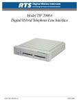
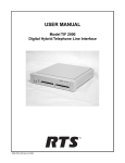
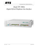
USER INSTRUCTIONS
MODEL CSI-200
COAXIAL SYSTEM INTERFACE
9350-7676-000 Rev B, 5/2001
PROPRIETARY NOTICE
The RTS product information and design disclosed herein were originated by and are the property of Telex Communications, Inc. telex reserves all patent, proprietary design, manufacturing, reproduction, use and sales rights
thereto, and to any article disclosed therein, except to the extent rights are expressly granted to others.
COPYRIGHT NOTICE
Copyright © 2000 by Telex Communications, Inc. All rights reserved. Reproduction in whole or in part without
prior written permission from Telex is prohibited.
UNPACKING AND INSPECTION
Immediately upon receipt of the equipment, inspect the shipping container and the contents carefully for any discrepancies or damage. Should there be any, notify the freight company and the dealer at once.
WARRANTY INFORMATION
RTS products are warranted by Telex Communications, Inc. to be free from defects in materials and workmanship
for a period of three years from the date of sale.
The sole obligation of Telex during the warranty period is to provide, without charge, parts and labor necessary to
remedy covered defects appearing in products returned prepaid to Telex. This warranty does not cover any defect,
malfunction or failure caused beyond the control of Telex, including unreasonable or negligent operation, abuse,
accident, failure to follow instructions in the Service Manual or the User Manual, defective or improper associated
equipment, attempts at modification and repair not authorized by Telex, and shipping damage. Products with their
serial numbers removed or effaced are not covered by this warranty.
To obtain warranty service, follow the procedures entitled “Procedure For Returns” and “Shipping to Manufacturer
for Repair or Adjustment”.
This warranty is the sole and exclusive express warranty given with respect to RTS products. It is the responsibility
of the user to determine before purchase that this product is suitable for the user's intended purpose.
ANY AND ALL IMPLIED WARRANTIES, INCLUDING THE IMPLIED WARRANTY OF MERCHANTABILITY ARE LIMITED TO THE DURATION OF THIS EXPRESS LIMITED WARRANTY.
NEITHER TELEX NOR THE DEALER WHO SELLS RTS PRODUCTS IS LIABLE FOR INCIDENTAL OR
CONSEQUENTIAL DAMAGES OF ANY KIND.
CUSTOMER SUPPORT
Technical questions should be directed to:
Customer Service Department
RTS/Telex
2550 Hollywood Way, Suite 207
Burbank, CA 91505 U.S.A.
Telephone: (818) 566-6700
Fax: (818) 843-7953
RETURN SHIPPING INSTRUCTIONS
PROCEDURE FOR RETURNS
If a repair is necessary, contact the dealer where this unit was purchased.
If repair through the dealer is not possible, obtain a RETURN AUTHORIZATION from:
Customer Service Department
Telex Communications, Inc.
Telephone: (800) 828-6107
Fax: (800) 323-0498
DO NOT RETURN ANY EQUIPMENT DIRECTLY TO THE FACTORY WITHOUT FIRST OBTAINING A
RETURN AUTHORIZATION.
Be prepared to provide the company name, address, phone number, a person to contact regarding the repair, the type
and quantity of equipment, a description of the problem and the serial number(s).
SHIPPING TO MANUFACTURER FOR REPAIR OR ADJUSTMENT
All shipments of RTS products should be made via United Parcel Service or the best available shipper, prepaid. The
equipment should be shipped in the original packing carton; if that is not available, use any suitable container that is
rigid and of adequate size. If a substitute container is used, the equipment should be wrapped in paper and surrounded
with at least four inches of excelsior or similar shock-absorbing material. All shipments must be sent to the following
address and must include the Return Authorization.
Factory Service Department
Telex Communications, Incorporated
West 1st Street
Blue Earth, MN 56013 U.S.A.
Upon completion of any repair the equipment will be returned via United Parcel Service or specified shipper collect.
End-User License Agreement for Telex® Software
IMPORTANT - Please read this document carefully before using this product.
THIS DOCUMENT STATES THE TERMS AND CONDITIONS UPON WHICH TELEX COMMUNICATIONS,
INC. (the “COMPANY”) OFFERS TO LICENSE THE INSTALLED SOFTWARE OR PROGRAM (the “SOFTWARE”) FOR USE WITH THE PRODUCT IN WHICH IT WAS INSTALLED. YOU ARE AGREEING TO
BECOME BOUND BY THE TERMS OF THIS AGREEMENT. IF YOU DO NOT AGREE TO THE TERMS OF
THIS AGREEMENT, DO NOT USE THIS PRODUCT. PROMPTLY RETURN THE PRODUCT TO THE
PLACE WHERE YOU OBTAINED IT FOR A FULL REFUND.
The installed software as supplied by the Company is licensed, not sold, to you for use only under the terms of this
license, and the Company reserves all rights not expressly granted to you. You own the product or other media on or
in which the Software is originally or subsequently recorded or fixed, but the Company retains ownership of all
copies of the Software itself.
1. License: This license allows you to use the Software for internal purposes only on a single product in which it
was installed.
2. Restrictions: (a) You may not market, distribute or transfer copies of the Software to others or electronically
transfer or duplicate the Software. YOU MAY NOT REVERSE ENGINEER, DECOMPILE, DISASSEMBLE,
MODIFY, ADAPT, TRANSLATE, RENT, LEASE OR LOAN THE SOFTWARE OR CREATE DERIVATIVE
WORKS BASED ON THE SOFTWARE OR ANY ACCOMPANYING WRITTEN MATERIALS. (b) The Software and the accompanying written materials are copyrighted. Unauthorized copying of the Software, including
portions thereof or the written materials, is expressly forbidden. (c) You understand that the Company may update
or revise the Software and in so doing incurs no obligation to furnish such updates to you.
3. Limited Warranty: The Company does not warrant that the operation of the Software will meet your requirements or operate free from error. The Company DISCLAIMS ALL OTHER WARRANTIES AND CONDITIONS
EITHER EXPRESS OR IMPLIED, INCLUDING THE WARRANTIES OF MERCHANTABILITY, FITNESS
FOR A PARTICULAR PURPOSE AND NON-INFRINGEMENT OF THIRD PARTY RIGHTS.
4. Limited Liability: The liability of the Company for any claims arising out of this License based upon the Software, regardless of the form of action, shall not exceed the greater of the license fee for the Software or $50.
TABLE OF CONTENTS
Introduction
1-1
Description . . . . . . . . . . . . . . . . . . .
Front Panel Features . . . . . . . . . . . . . .
Rear Panel Features . . . . . . . . . . . . . .
Typical Configurations . . . . . . . . . . . . .
1. Matrix to Keypanel . . . . . . . . . . . .
2. Matrix to Two Keypanels, Two CSI-200s .
3. Matrix to Two Keypanels, Three CSI-200s
Example of a Typical System . . . . . . . . . .
Power Requirements . . . . . . . . . . . . . .
.
.
.
.
.
.
.
.
.
.
.
.
.
.
.
.
.
.
.
.
.
.
.
.
.
.
.
.
.
.
.
.
.
.
.
.
.
.
.
.
.
.
.
.
.
.
.
.
.
.
.
.
.
.
.
.
.
.
.
.
.
.
.
.
.
.
.
.
.
.
.
.
.
.
.
.
.
.
.
.
.
.
.
.
.
.
.
.
.
.
.
.
.
.
.
.
.
.
.
.
.
.
.
.
.
.
.
.
.
.
.
.
.
.
.
.
.
.
.
.
.
.
.
.
.
.
.
.
.
.
.
.
.
.
.
.
.
.
.
.
.
.
.
.
.
.
.
.
.
.
.
.
.
.
.
.
.
.
.
.
.
.
.
.
.
.
.
.
.
.
.
.
.
.
.
.
.
.
.
.
.
.
.
.
.
.
.
.
.
.
.
.
.
.
.
.
.
.
.
.
.
.
.
.
.
.
.
.
.
.
.
.
.
.
.
.
.
.
.
.
.
.
.
.
.
.
.
.
.
.
.
.
.
.
.
.
.
.
.
.
.
.
.
.
.
.
.
.
.
.
.
.
.
.
.
.
.
.
.
.
.
.
.
.
.
.
.
.
.
.
.
.
.
.
.
.
.
.
.
.
.
.
.
.
.
.
.
.
.
.
.
.
.
.
.
.
.
.
.
.
.
.
.
.
.
.
.
.
.
.
.
.
.
.
.
.
.
.
.
.
.
.
.
.
.
.
.
.
.
.
.
.
.
.
.
.
.
.
.
.
.
.
Installation
2-1
Unpacking and Inspection . . . .
Mounting the CSI-200 . . . . . .
Matrix to CSI-200 Connections . .
Keypanel to CSI-200 Connections
CSI-200 to CSI-200 Connections .
Verifying Proper Operation . . . .
Troubleshooting . . . . . . . . . .
.
.
.
.
.
.
.
.
.
.
.
.
.
.
.
.
.
.
.
.
.
.
.
.
.
.
.
.
.
.
.
.
.
.
.
.
.
.
.
.
.
.
.
.
.
.
.
.
.
.
.
.
.
.
.
.
.
.
.
.
.
.
.
.
.
.
.
.
.
.
.
.
.
.
.
.
.
.
.
.
.
.
.
.
.
.
.
.
.
.
.
.
.
.
.
.
.
.
.
.
.
.
.
.
.
.
.
.
.
.
.
.
.
.
.
.
.
.
.
.
.
.
.
.
.
.
.
.
.
.
.
.
.
.
.
.
.
.
.
.
.
.
.
.
.
.
.
.
.
.
.
.
.
.
.
.
.
.
.
.
.
.
.
.
.
.
.
.
.
.
.
.
.
.
.
.
.
.
.
.
.
.
.
.
.
.
.
.
.
.
.
.
.
.
.
.
.
.
.
.
.
.
.
.
.
.
.
.
.
.
.
.
.
.
.
.
.
.
.
.
.
.
.
.
.
.
.
.
.
.
.
.
.
.
.
.
.
.
.
.
.
.
.
.
.
.
.
.
.
.
.
.
.
.
.
.
.
.
.
.
.
.
.
.
.
.
.
.
.
.
.
.
.
.
.
.
.
.
.
.
.
.
.
.
.
.
.
.
.
.
.
.
.
.
.
.
.
.
.
.
.
.
.
.
.
.
.
.
.
.
.
.
.
.
.
.
.
.
.
.
.
.
.
.
.
.
.
.
.
.
.
.
.
.
.
.
.
.
.
.
.
.
.
.
.
.
.
.
.
.
.
.
.
.
.
.
.
.
.
.
.
.
.
.
.
.
.
.
.
.
.
.
.
.
.
.
.
.
.
.
.
.
.
.
.
.
.
.
.
.
.
.
.
.
.
.
.
.
.
.
.
.
.
.
.
.
.
.
.
.
.
.
.
.
.
.
.
.
.
.
.
.
.
.
.
.
.
.
.
.
.
.
.
.
.
.
.
.
.
.
.
.
.
.
.
.
.
.
.
.
.
.
.
.
.
.
.
.
.
.
.
.
.
.
.
.
.
.
.
.
.
.
.
.
.
.
.
.
.
.
.
.
.
.
.
.
.
.
.
.
.
.
.
.
.
.
.
.
.
.
.
.
.
.
.
.
.
.
.
.
.
.
.
.
.
.
.
.
.
.
.
.
.
.
.
.
.
.
.
.
.
.
.
.
.
.
.
.
.
.
.
.
.
.
.
.
.
.
.
.
.
.
.
.
.
.
.
.
.
.
.
.
.
.
.
.
.
.
.
.
.
.
.
.
.
.
.
.
.
.
.
.
.
.
.
.
.
.
.
.
.
.
.
.
.
.
.
.
.
.
.
.
.
.
.
.
.
.
.
.
.
.
.
.
.
.
.
.
.
.
.
.
.
.
.
.
.
.
.
.
Specifications
Audio Performance .
Ports . . . . . . . .
Power . . . . . . . .
Physical . . . . . . .
Operating Conditions
Storage Conditions .
Agency Approvals. .
1-1
1-1
1-2
1-2
1-2
1-2
1-3
1-3
1-3
2-1
2-1
2-3
2-3
2-4
2-4
2-4
3-1
.
.
.
.
.
.
.
.
.
.
.
.
.
.
.
.
.
.
.
.
.
.
.
.
.
.
.
.
.
.
.
.
.
.
.
.
.
.
.
.
.
.
.
.
.
.
.
.
.
i
3-1
3-1
3-1
3-1
3-2
3-2
3-2
This page left blank intentionally.
ii
LIST OF FIGURES
Figure 1.1
Figure 1.2
Figure 1.3
Figure 2.1
Figure 2.2
Figure 2.3
Figure 2.4
Figure 2.5
Figure 2.6
CSI-200 front panel. . . . . . . . . .
CSI-200 rear panel. . . . . . . . . . .
Single channel CSI-200 configuration.
MCP1 dual rack mount kit. . . . . . .
MCP2 single rack mount kit. . . . . .
MCP3 console mount kit. . . . . . . .
MCP4 tandem mount kit . . . . . . .
9-pin intercom cable wiring diagram. .
CSI-200 link cable. . . . . . . . . . .
.
.
.
.
.
.
.
.
.
.
.
.
.
.
.
.
.
.
.
.
.
.
.
.
.
.
.
.
.
.
.
.
.
.
.
.
.
.
.
.
.
.
.
.
.
iii
.
.
.
.
.
.
.
.
.
.
.
.
.
.
.
.
.
.
.
.
.
.
.
.
.
.
.
.
.
.
.
.
.
.
.
.
.
.
.
.
.
.
.
.
.
.
.
.
.
.
.
.
.
.
.
.
.
.
.
.
.
.
.
.
.
.
.
.
.
.
.
.
.
.
.
.
.
.
.
.
.
.
.
.
.
.
.
.
.
.
.
.
.
.
.
.
.
.
.
.
.
.
.
.
.
.
.
.
.
.
.
.
.
.
.
.
.
.
.
.
.
.
.
.
.
.
.
.
.
.
.
.
.
.
.
.
.
.
.
.
.
.
.
.
.
.
.
.
.
.
.
.
.
.
.
.
.
.
.
.
.
.
.
.
.
.
.
.
.
.
.
.
.
.
.
.
.
.
.
.
.
.
.
.
.
.
.
.
.
.
.
.
.
.
.
.
.
.
.
.
.
.
.
.
.
.
.
.
.
.
.
.
.
.
.
.
.
.
.
.
.
.
.
.
.
. 1-1
. 1-2
. 1-3
. 2-2
. 2-2
. 2-2
. 2-2
. 2-3
. 2-4
This page left blank intentionally.
iv
S
E C T I O N
INTRODUCTION
CHAPTER1
Description
The CSI-200 is a bidirectional, two-channel coaxial interface which passes digital audio and
control between RTS™ brand keypanels and matrices. At 1RU high and half-rack width, the
CSI-200 is compact allowing up to four coaxial channels in a standard rack space. Installation of
the CSI-200 is quick and simplified with no user settings. Channel cabling and power connections
are all that is needed to set up the interface. Each CSI-200 will monitor its interface lines to
automatically determine the type of equipment to which it is attached. Each of the two channels of
the CSI-200 are independent and may operate in either the keypanel or matrix modes. LEDs
provide the user with status information on the unit’s connections.
Front Panel Features
Figure 1.1
CSI-200 front panel.
1 Indicates the power status of the unit (green = on).
2 Used to reset the unit.
3 Indicates the connection status of the port. A green Frame LED indicates that the
corresponding port on the rear of the unit is connected to the matrix end of the link. A green
Keypanel LED indicates that the corresponding port on the rear of the unit is connected to the
keypanel end of the link.
4 Indicates the transmission (TX) or reception (RX) of data for the indicated channel.
1-1
Rear Panel Features
Figure 1.2
CSI-200 rear panel.
1 IEC male type power connection. Accepts 90-240 VAC with a line frequency of 47-63 Hz.
Plugging the unit into AC power automatically powers the unit on.
2 BNC female type connector. Provides the link for the designated channel from CSI-200. Use
Belden 8281 or equivalent type cable with a 75 ohm characteristic impedance. The maximum
run length is about 1,000 feet (305 meters).
3 DB-9 female type connector. Provides the link for the designated channel to the matrix. Use
standard CAT V type cable.
4 DB-9 male type connector. Provides the link for the designated channel to the keypanel. Use
standard CAT V type cable.
Typical Configurations
There are three typical configurations when using the CSI-200:
1. Matrix to Keypanel
One CSI-200 is located at a matrix and the other CSI-200 at a keypanel. Each CSI-200 is cabled
to their respective matrix or keypanel via a standard CAT V cable. A dual-gender 9-pin port for
both channels is provided at the rear of the CSI-200 to accommodate connection to either matrix
or keypanel. The channel connection is completed by cabling a 75 ohm video coaxial cable
(Belden 8281 is recommended) between the CSI-200s.
2. Matrix to Two Keypanels, Two CSI-200s
In the two CSI-200 configuration above, only one of the channels are used. Adding an additional
coaxial line between to the second CSI-200 channel allows a user to connect a separate keypanel
through the same CSI-200 units.
1-2
CSI-200 User Instructions
3. Matrix to Two Keypanels, Three CSI-200s
With three CSI-200s, one CSI-200 is located at the matrix and the other two CSI-200s at their
respective keypanels. The maximum distance between the two keypanels is extended to 2,000 feet
plus the usual CAT V cabling configuration separation distance. This assumes that the matrix is
located at the center of the configuration.
Example of a Typical System
Below is an example of a typical single channel system:
Figure 1.3
Single channel CSI-200 configuration.
Power Requirements
A standard IEC type connection is provided. The switching power supply accepts all country
voltages from 90 - 240 VAC, with a line frequency of 47 - 63 Hz.
1-3
This page left blank intentionally.
1-4
CSI-200 User Instructions
S
E C T I O N
INSTALLATION
CHAPTER2
Unpacking and Inspection
As soon as possible after receipt, inspect the box and contents for physical damage that may have
occurred in shipping. If damage is noted, immediately (within 24 hours of receipt of equipment)
contact the carrier involved and file a claim. Save all packing materials, and request an immediate
inspection by the carrier’s insurance claims agent.
The box should contain the following items:
Note
Quantity
Description
1
CSI-200 Interface
1
Power Cord
1
User Manual
Refer to the front of this manual for information regarding returns to RTS.
Mounting the CSI-200
The CSI-200 can be mounted using a wide variety of MCP mounting kits. Remember to leave
adequate room behind the unit for cable access. There are no special ventilation requirements.
Some of the possible configurations are:
1 Dual Rack Mount (Figure 2.1)
2 Single Rack Mount (Figure 2.2)
3 Console Mount (Figure 2.3)
4 Tandem Mount (Figure 2.4)
2-1
2-2
Figure 2.1
MCP1 dual rack mount kit.
Figure 2.2
MCP2 single rack mount kit.
Figure 2.3
MCP3 console mount kit.
Figure 2.4
MCP4 tandem mount kit
CSI-200 User Manual
Matrix to CSI-200 Connections
The CSI-200 requires a standard RTS 9-pin D-Sub intercom cable for matrix connections. Refer
to Figure 2.5 for connector pinout. To connect the CSI-200 to the matrix do the following:
1 Plug one end of the cable into the appropriate Frame connector on the rear panel of the
CSI-200.
2 Plug the other end into the appropriate port of the intercom system. (This will be the port
Note
number that you designated previously when setting the address switch on the keypanel.)
The CSI-200 may be connected while the intercom system is running.
Figure 2.5
Note
9-pin intercom cable wiring diagram.
When connecting a CSI-200 to a matrix, treat the CSI-200 as if it were a keypanel. When
connecting a CSI-200 to a keypanel, treat the CSI-200 as the matrix.
Keypanel to CSI-200 Connections
The CSI-200 requires a standard RTS 9-pin D-Sub intercom cable. Refer to Figure 2.5 for
connector pinout. To connect the CSI-200 to a keypanel do the following:
1 Plug one end of the cable into the appropriate Keypanel connector on the rear panel of the
CSI-200.
2 Plug the other end into the Frame connector of the keypanel.
Note
The Keypanel may be connected while the intercom system is running.
2-3
CSI-200 to CSI-200 Connections
The CSI-200 interfaces are connected via standard 75 ohm video cables terminated with male
BNC connectors on each end. The use of Belden 8281 or equivalent is recommended. Refer to
Figure 2.6 for an example of the cable. To connect the CSI-200 located at the matrix end of the
link to the CSI-200 located at the keypanel end on the link do the following:
1 Plug one end of the cable into the appropriate coax connector on the rear panel of the CSI-
200 attached to the matrix.
2 Plug the other end into the coax connector on the rear panel of the CSI-200 attached to the
keypanel, or directly to a KP-32 keypanel equipped with a coaxial interface.
Figure 2.6
CSI-200 link cable.
Verifying Proper Operation
The CSI-200 does not require special settings for it to establish a link. Once the proper cable
connections are made and power is applied to the units, a link should automatically establish
itself. To verify proper linking do the following:
1 Check the Mode LEDs on the front panel of the CSI-200 located at the matrix end of the
link. The Frame LED should be illuminated for each channel (A and/or B) that is connected
to the matrix.
2 Check the Mode LEDs on the front panel of the CSI-200 located at the keypanel end of the
link. The Keypanel LED should be illuminated for each channel (A and/or B) that is
connected to a keypanel.
3 Check the Tx and Rx LEDs on the front panel of each CSI-200. You should see them
periodically illuminate (green) for each channel (A and/or B) that is connected.
Troubleshooting
If the CSI-200 fails to function as outlined in “Verifying Proper Operation,” do the following:
1 Check the Power LED located on the front panel of each CSI-200. If the LED is not
illuminated (green), verify that the unit is plugged into an AC power outlet that is
functioning properly.
2 Check the Frame, Rx, and Tx LEDs on the front panel of the CSI-200 attached to the matrix.
If the Tx LED is the only one illuminated (green), verify that the coaxial cable is properly
wired and connected.
3 Check the cables connecting the CSI-200 to the matrix.
4 Check the cables connecting the CSI-200 to the keypanel.
5 Press the Reset button on each CSI-200.
Note
2-4
The Frame and Keypanel LEDs are turned on during the initialization of the link. The Frame and
Keypanel LEDs will not turn off if one or both of the data/audio cables is broken after the link has
been initialized. If the coaxial cable linking the two CSI-200s is broken, the Frame and Keypanel
LEDs will turn off.
CSI-200 User Manual
S
E C T I O N
SPECIFICATIONS
CHAPTER3
Audio Performance
SNR @ 8 dBu (A-weighted). . . . . . . . . . >70 dB
THD+N @ 8 dBu (un-weighted). . . . . . . . . . <0.1%
Frequency Response. . . . . . . . . . 100 Hz - 20k Hz ″ 1 dB
Operating Level. . . . . . . . . . +8 dBu
Maximum Level. . . . . . . . . . +20 dBu
Input/Output. . . . . . . . . . Balanced Hi-Z
Crosstalk. . . . . . . . . . >70 dB
Ports
Keypanel/Matrix:
Coax I/F:
Two 9-pin D-Sub, male/female, stacked port connectors (1 stack per
channel with audio in, audio out, and RS-485 signals.
Two BNC female connectors with 75 ohm terminations.
Power
Line Voltage:
Frequency:
Consumption:
90-240 VAC
47-63 Hz
15 VA (Max.)
Physical
Dimensions:
Weight:
Finish:
1.72” (44mm) high X 8.19” (208mm) wide X 8” (203mm) deep
2.8 lbs. (1.28 kg)
Thermoplastic front panel, extruded aluminum case, light gray finish
3-1
Operating Conditions
Temperature:
Humidity:
-4°F to 122°F (-20°C to 50°C)
0 to 95%, non-condensing
Storage Conditions
Temperature:
Humidity:
Agency Approvals
UL, CSA, CE, C-Tick
3-2
CSI-200 User Manual
-40°F to 185°F (-40°C to 85°C)
0 to 95%, non-condensing