1
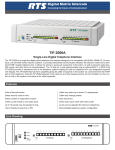
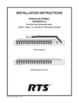
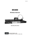
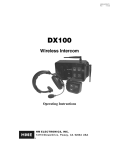
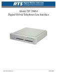
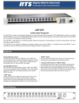
USER INSTRUCTIONS
ZEUS KEYPANEL
USER MANUAL
9350-7646-000 Rev L, 11/2004
PROPRIETARY NOTICE
The RTS product information and design disclosed herein were originated by and are the property of Telex Communications, Inc. telex reserves all patent, proprietary design, manufacturing, reproduction, use and sales rights
thereto, and to any article disclosed therein, except to the extent rights are expressly granted to others.
COPYRIGHT NOTICE
Copyright © 2004 by Telex Communications, Inc. All rights reserved. Reproduction in whole or in part without
prior written permission from Telex is prohibited.
UNPACKING AND INSPECTION
Immediately upon receipt of the equipment, inspect the shipping container and the contents carefully for any discrepancies or damage. Should there be any, notify the freight company and the dealer at once.
WARRANTY INFORMATION
See the enclosed warranty card for further details.
CUSTOMER SUPPORT
Technical questions should be directed to:
Customer Service Department
RTS/Telex Communications, Inc.
12000 Portland Avenue South
Burnsville, MN 55337 U.S.A.
Telephone: (800) 392-3497
Fax: (800) 323-0498
RETURN SHIPPING INSTRUCTIONS
PROCEDURE FOR RETURNS
If a repair is necessary, contact the dealer where this unit was purchased.
If repair through the dealer is not possible, obtain a RETURN AUTHORIZATION from:
Customer Service Department
Telex Communications, Inc.
Telephone: (800) 392-3497
Fax: (800) 323-0498
DO NOT RETURN ANY EQUIPMENT DIRECTLY TO THE FACTORY WITHOUT FIRST OBTAINING A
RETURN AUTHORIZATION.
Be prepared to provide the company name, address, phone number, a person to contact regarding the repair, the type
and quantity of equipment, a description of the problem and the serial number(s).
SHIPPING TO MANUFACTURER FOR REPAIR OR ADJUSTMENT
All shipments of RTS products should be made via United Parcel Service or the best available shipper, prepaid. The
equipment should be shipped in the original packing carton; if that is not available, use any suitable container that is
rigid and of adequate size. If a substitute container is used, the equipment should be wrapped in paper and surrounded
with at least four inches of excelsior or similar shock-absorbing material. All shipments must be sent to the following
address and must include the Return Authorization.
Factory Service Department
Telex Communications, Incorporated
1930 West 1st Street
Blue Earth, MN 56013 U.S.A.
Upon completion of any repair the equipment will be returned via United Parcel Service or specified shipper collect.
End-User License Agreement for Telex® Software
IMPORTANT - Please read this document carefully before using this product.
THIS DOCUMENT STATES THE TERMS AND CONDITIONS UPON WHICH TELEX COMMUNICATIONS,
INC. (the “COMPANY”) OFFERS TO LICENSE THE INSTALLED SOFTWARE OR PROGRAM (the “SOFTWARE”) FOR USE WITH THE PRODUCT IN WHICH IT WAS INSTALLED. YOU ARE AGREEING TO
BECOME BOUND BY THE TERMS OF THIS AGREEMENT. IF YOU DO NOT AGREE TO THE TERMS OF
THIS AGREEMENT, DO NOT USE THIS PRODUCT. PROMPTLY RETURN THE PRODUCT TO THE
PLACE WHERE YOU OBTAINED IT FOR A FULL REFUND.
The installed software as supplied by the Company is licensed, not sold, to you for use only under the terms of this
license, and the Company reserves all rights not expressly granted to you. You own the product or other media on
or in which the Software is originally or subsequently recorded or fixed, but the Company retains ownership of all
copies of the Software itself.
1. License: This license allows you to use the Software for internal purposes only on a single product in which it
was installed.
2. Restrictions: (a) You may not market, distribute or transfer copies of the Software to others or electronically
transfer or duplicate the Software. YOU MAY NOT REVERSE ENGINEER, DECOMPILE, DISASSEMBLE,
MODIFY, ADAPT, TRANSLATE, RENT, LEASE OR LOAN THE SOFTWARE OR CREATE DERIVATIVE
WORKS BASED ON THE SOFTWARE OR ANY ACCOMPANYING WRITTEN MATERIALS. (b) The Software and the accompanying written materials are copyrighted. Unauthorized copying of the Software, including
portions thereof or the written materials, is expressly forbidden. (c) You understand that the Company may update
or revise the Software and in so doing incurs no obligation to furnish such updates to you.
3. Limited Warranty: The Company does not warrant that the operation of the Software will meet your requirements or operate free from error. The Company DISCLAIMS ALL OTHER WARRANTIES AND CONDITIONS
EITHER EXPRESS OR IMPLIED, INCLUDING THE WARRANTIES OF MERCHANTABILITY, FITNESS
FOR A PARTICULAR PURPOSE AND NON-INFRINGEMENT OF THIRD PARTY RIGHTS.
4. Limited Liability: The liability of the Company for any claims arising out of this License based upon the Software, regardless of the form of action, shall not exceed the greater of the license fee for the Software or $50.
TABLE OF CONTENTS
GENERAL DESCRIPTION . . . . . . . . . . . . . . . . . . . . . . . . .
FEATURES . . . . . . . . . . . . . . . . . . . . . . . . . . . . . . . . .
FRONT PANEL DESCRIPTION . . . . . . . . . . . . . . . . . . . . . .
BACK PANEL / CIRCUIT BOARD SWITCHES AND CONNECTORS . . .
SPECIFICATIONS . . . . . . . . . . . . . . . . . . . . . . . . . . . . .
UNPACKING AND INSPECTION. . . . . . . . . . . . . . . . . . . . . .
WKP-4 BOX INSTALLATION . . . . . . . . . . . . . . . . . . . . . . . .
TKP-4 BOX INSTALLATION . . . . . . . . . . . . . . . . . . . . . . . .
CONFIGURATION SWITCHES . . . . . . . . . . . . . . . . . . . . . .
DIP Switches . . . . . . . . . . . . . . . . . . . . . . . . . . . . . .
DIP Switch 1 . . . . . . . . . . . . . . . . . . . . . . . . . . . . .
DIP Switch 2 . . . . . . . . . . . . . . . . . . . . . . . . . . . . .
DIP Switch 3 . . . . . . . . . . . . . . . . . . . . . . . . . . . . .
DIP Switch 4 . . . . . . . . . . . . . . . . . . . . . . . . . . . . .
DIP Switch 5 . . . . . . . . . . . . . . . . . . . . . . . . . . . . .
DIP Switch 6 . . . . . . . . . . . . . . . . . . . . . . . . . . . . .
DIP Switch 7 . . . . . . . . . . . . . . . . . . . . . . . . . . . . .
DIP Switch 8 . . . . . . . . . . . . . . . . . . . . . . . . . . . . .
Address Switch . . . . . . . . . . . . . . . . . . . . . . . . . . . . .
MOUNTING THE MKP-4 . . . . . . . . . . . . . . . . . . . . . . . . . .
CONNECTIONS . . . . . . . . . . . . . . . . . . . . . . . . . . . . . .
Mic Connector . . . . . . . . . . . . . . . . . . . . . . . . . . . . . .
Headset Connector . . . . . . . . . . . . . . . . . . . . . . . . . . .
Connection To Intercom System. . . . . . . . . . . . . . . . . . . . .
BKP-4 Connection . . . . . . . . . . . . . . . . . . . . . . . . . .
TKP-4 / WKP-4 Connection . . . . . . . . . . . . . . . . . . . . .
Power Connection . . . . . . . . . . . . . . . . . . . . . . . . . . . .
STARTUP AND OPERATIONAL CHECK . . . . . . . . . . . . . . . . .
ASSIGNING INTERCOM KEYS . . . . . . . . . . . . . . . . . . . . . .
CLEARING KEY ASSIGNMENTS . . . . . . . . . . . . . . . . . . . . .
CHANGING SETUP PAGES . . . . . . . . . . . . . . . . . . . . . . . .
HEADSET BUTTON OPERATION . . . . . . . . . . . . . . . . . . . . .
DIP switch 4 in Open position (default) . . . . . . . . . . . . . . . . .
DIP switch 4 in Closed position . . . . . . . . . . . . . . . . . . . . .
VOLUME ADJUSTMENT . . . . . . . . . . . . . . . . . . . . . . . . . .
INTERCOM KEY OPERATION . . . . . . . . . . . . . . . . . . . . . . .
Momentary vs. Latching Operation . . . . . . . . . . . . . . . . . . .
Intercom Key Operation for Different Types of Key Assignments . . . .
Intercom Key Indications . . . . . . . . . . . . . . . . . . . . . . . .
Talk Indicator:. . . . . . . . . . . . . . . . . . . . . . . . . . . . .
Listen Indicator: . . . . . . . . . . . . . . . . . . . . . . . . . . .
CALL WAITING OPERATION FOR INCOMING CALLS . . . . . . . . . .
OPERATION WITH THE TIF-951 & TIF-2000 TELEPHONE INTERFACE.
DISPLAYING KEY ASSIGNMENTS . . . . . . . . . . . . . . . . . . . .
DISPLAYING THE PORT NUMBER . . . . . . . . . . . . . . . . . . . .
SIDETONE ADJUSTMENT . . . . . . . . . . . . . . . . . . . . . . . . .
i
.
.
.
.
.
.
.
.
.
.
.
.
.
.
.
.
.
.
.
.
.
.
.
.
.
.
.
.
.
.
.
.
.
.
.
.
.
.
.
.
.
.
.
.
.
.
.
.
.
.
.
.
.
.
.
.
.
.
.
.
.
.
.
.
.
.
.
.
.
.
.
.
.
.
.
.
.
.
.
.
.
.
.
.
.
.
.
.
.
.
.
.
.
.
.
.
.
.
.
.
.
.
.
.
.
.
.
.
.
.
.
.
.
.
.
.
.
.
.
.
.
.
.
.
.
.
.
.
.
.
.
.
.
.
.
.
.
.
.
.
.
.
.
.
.
.
.
.
.
.
.
.
.
.
.
.
.
.
.
.
.
.
.
.
.
.
.
.
.
.
.
.
.
.
.
.
.
.
.
.
.
.
.
.
.
.
.
.
.
.
.
.
.
.
.
.
.
.
.
.
.
.
.
.
.
.
.
.
.
.
.
.
.
.
.
.
.
.
.
.
.
.
.
.
.
.
.
.
.
.
.
.
.
.
.
.
.
.
.
.
.
.
.
.
.
.
.
.
.
.
.
.
.
.
.
.
.
.
.
.
.
.
.
.
.
.
.
.
.
.
.
.
.
.
.
.
.
.
.
.
.
.
.
.
.
.
.
.
.
.
.
.
.
.
.
.
.
.
.
.
.
.
.
.
.
.
.
.
.
.
.
.
.
.
.
.
.
.
.
.
.
.
.
.
.
.
.
.
.
.
.
.
.
.
.
.
.
.
.
.
.
.
.
.
.
.
.
.
.
.
.
.
.
.
.
.
.
.
.
.
.
.
.
.
.
.
.
.
.
.
.
.
.
.
.
.
.
.
.
.
.
.
.
.
.
.
.
.
.
.
.
.
.
.
.
.
.
.
.
.
.
.
.
.
.
.
.
.
.
.
.
.
.
.
.
.
.
.
.
.
.
.
.
.
.
.
.
.
.
.
.
.
.
.
.
.
.
.
.
.
.
.
.
.
.
.
.
.
.
.
.
.
.
.
.
.
.
.
.
.
.
.
.
.
.
.
.
.
.
.
.
.
.
.
.
.
.
.
.
.
.
.
.
.
.
.
.
.
.
.
.
.
.
.
.
.
.
.
.
.
.
.
.
.
.
.
.
.
.
.
.
.
.
.
.
.
.
.
.
.
.
.
.
.
.
.
.
.
.
.
.
.
.
.
.
.
.
.
.
.
.
.
.
.
.
.
.
.
.
.
.
.
.
.
.
.
.
.
.
.
.
.
.
.
.
.
.
.
.
.
.
.
.
.
.
.
.
.
.
.
.
.
.
.
.
.
.
.
.
.
.
.
.
.
.
.
.
.
.
.
.
.
.
.
.
.
.
.
.
.
.
.
.
.
.
.
.
.
.
.
.
.
.
.
.
.
.
.
.
.
.
.
.
.
.
.
.
.
.
.
.
.
.
.
.
.
.
.
.
.
.
.
.
.
.
.
.
.
.
.
.
.
.
.
.
.
.
.
.
.
.
.
.
.
.
.
.
.
.
.
.
.
.
.
.
.
.
.
.
.
.
.
.
.
.
.
.
.
.
.
.
.
.
.
.
.
.
.
.
.
.
.
.
.
.
.
.
.
.
.
.
.
.
.
.
.
.
.
.
.
.
.
.
.
.
.
.
.
.
.
.
.
.
.
.
.
.
.
.
.
.
.
.
.
.
.
.
.
.
.
.
.
.
.
.
.
.
.
.
.
.
.
.
.
.
.
.
.
.
.
.
.
.
.
.
.
.
.
.
.
.
.
.
.
.
.
.
.
.
.
.
.
.
.
.
.
.
.
.
.
.
.
.
.
.
.
.
.
.
.
.
.
.
.
.
.
.
.
.
.
.
.
.
.
.
.
.
.
.
.
.
.
.
.
.
.
.
.
.
.
.
.
.
.
.
.
.
.
.
.
.
.
.
.
.
.
.
.
.
.
.
.
.
.
.
.
.
.
.
.
.
.
.
.
.
.
.
.
.
.
.
.
.
.
.
.
.
.
.
.
.
.
.
.
.
.
.
.
.
.
.
.
.
.
.
.
.
.
.
.
.
.
.
.
.
.
.
.
.
.
.
.
.
.
.
.
.
.
.
.
.
.
.
.
.
.
.
.
.
.
.
.
.
.
.
.
.
.
.
.
.
.
.
.
.
.
.
.
.
.
.
.
.
.
.
.
.
.
.
.
.
.
.
.
.
.
.
.
.
.
.
.
.
.
.
.
.
.
.
.
.
.
.
.
.
.
.
.
.
.
.
.
.
.
.
.
.
.
.
.
.
.
.
.
.
.
.
.
.
.
.
.
.
.
.
.
.
.
.
.
.
.
.
.
.
.
.
.
.
.
.
.
.
.
.
.
.
.
. 1-1
. 1-1
. 1-2
. 1-4
. 1-6
. 2-1
. 2-2
. 2-2
. 2-3
. 2-3
. 2-3
. 2-3
. 2-3
. 2-3
. 2-3
. 2-4
. 2-4
. 2-4
. 2-4
. 2-7
. 2-8
. 2-8
. 2-8
. 2-8
. 2-9
. 2-10
. 2-10
. 2-11
. 3-1
. 3-2
. 3-2
. 4-1
. 4-1
. 4-1
. 4-1
. 4-2
. 4-2
. 4-2
. 4-2
. 4-2
. 4-3
. 4-3
. 4-3
. 4-4
. 4-4
. 4-4
This page intentionally left blank.
ii
S
E C T I O N
1
DESCRIPTION & SPECIFICATIONS
CHAPTER1
GENERAL DESCRIPTION
The MKP-4, BKP-4. TKP-4, and WKP-4 are ideal for users who want full access to the most
commonly used keypanel features, and who generally communicate with four or less locations in
the intercom system at any given time. The MKP-4 can be rack mounted or used on a desktop and
is powered from an AC mains outlet. The BKP-4 is suitable for desktop use and is powered from
an AC mains outlet. The TKP-4 is designed to fit in a Tektronics equipment bay. The WKP-4 is
designed for wall mounting. The TKP-4 and WKP-4 may be ordered with an optional universal
AC power supply, or the installer can supply power from another source. The MKP-12 has the
same ease of use as the other units, but features a total of 12 assignable keys and a rack mountable
chassis.
FEATURES
• Works with ADAM™, ADAM™ CS and Zeus™ Digital Matrix Intercom Systems.
• Full-function intercom keys with LED indicators.
• Alphanumeric call waiting display with response key.
• Access to intercom key and setup page assignments.
• 4-wire, balanced audio input and output.
• Several microphone/speaker/headphone combinations possible, including: Headset
(microphone + headphones), headphones + panel mounted microphone, speaker + panel
mounted microphone, speaker + handheld microphone. Works with: RTS™ headsets with
A4M connector, MCP90 Panel Microphone and MCS325 Modular Speaker (MKP-4 only).
• Easy installation setup.
• The MKP-12 is one rack unit (RU) high and comes with ears for mounting in a standard 19
inch equipment rack. The MKP-4 is one rack unit (RU) high and ½ RU wide.
• The MKP-4 mounts in a standard equipment rack with RTS™ MCP rack mount hardware. Can
be mounted in the same rack unit with an MCS325 Modular Speaker.
• Ready for worldwide use. The BKP-4, MKP-4, and MKP-12 accept any mains voltage from
90-240 VAC, 47/63 Hz. The TKP-4 and WKP-4 can be powered from an optional AC adapter
which accepts 100-240 VAC, 47/63. Alternatively, the TKP-4 and WKP-4 may be powered
from a user-supplied, 15-24 VDC, 1 amp, regulated power source.)
1-1
FRONT PANEL DESCRIPTION
1 Intercom Keys: Assignable for several types of operation, including talk only, listen only, talk
with auto-listen, and all-call (where activating the key also activates all keys to the left of that
key). Keys feature momentary or latching operation. For momentary operation, the operator
presses and holds a key while communicating, then releases it when finished. For latching
operation, the operator taps a key to turn it on, then taps it again to turn it off. Latching can be
disabled via an options switch (12) or from ADAMedit or ZEUSedit.
2 Key Indicators: Two bi-color (red and green) LED indicators for each key. Provide indications
for talk on/off, listen on/off, incoming call, busy (for keys assigned to talk to IFB's), and in-use
(for keys assigned to talk to either IFB's or ISO's).
3 Designation Strip Holder: Holds printed strip identifying key assignments. Works with
ADAMedit and ZEUSedit designation strip print feature.
4 Call Waiting Display and Response Key: 4-character, alphanumeric display for incoming
caller names. Talkback to caller via the response key. The call waiting window and response
key are also used with the copy, clear, and scroll keys (5).
5 Copy, Clear, and Scroll keys: Used for key and setup page assignment. Can also be used to talk
to any location in the intercom system when no intercom key is assigned. (Note: There are 4
setup pages. Each contains a complete set of key assignments.)
6 Headset On/Off Key with Indicator. When the headset is on, the speaker output and panel mic
are off.
7 Listen Volume Control for Headset or Speaker.
8 Panel Mic Connector: 1/4", 3-conductor phone jack. Accepts MCP5 or MCP6 Panel
Microphone.
9 Monaural Headset Connector: A4F (XLR-4F) connector. Accepts any RTS headset with A4M
(XLR4M) connector. Also accepts monaural headphones for use with a panel microphone, or
accepts a handheld microphone for use with the speaker
1-2
User Instructions MKP-4, BKP-4, WKP-4, TKP-4, and MKP12 Keypanels
Figure 1.1
MKP-4 Front Panel View
Figure 1.2
BKP-4, TKP-4, WKP-4 Front Panel View
™
WKP-4
Mic
Headset
Call waiting
Copy
Clear
Listen
Talk
Headset
Volume
1
Figure 1.3
2
3
4
5
6
7
8
9
MKP-12 Front Panel View
1-3
BACK PANEL / CIRCUIT BOARD SWITCHES AND CONNECTORS
10 BKP-4: Universal Power Input: Accepts any mains voltage from 90-240 VAC, 47-63 Hz.
TKP-4 and WKP-4: Terminals for DC power connection.
11 Intercom Frame Connectors. All units have both 9-pin female D-sub (DE9S) and RJ12
connectors. The TKP-4 and WKP-4 also include spring-clamp terminals.
12 Options DIP Switches:
• Name Display for Assigned Keys: Assigned intercom keys provide an LED flash for incoming
call announce. Optionally, the caller's name can also be displayed in the call waiting window.
(Incoming calls from unassigned callers are always displayed in the call waiting window.)
• Incoming Call Timeout Select: Incoming call LED flash can be set for 15 seconds, or until the
caller's key is released.
• Speaker / Microphone Selection: A DIP switch, together with the front panel Headset switch,
permits any of the following speaker / microphone combinations: internal speaker with panel
microphone; headphones with panel microphone; speaker with 4-pin dynamic microphone;
headset with boom-mounted dynamic mic.
• Latching: The electronic latching feature for the intercom keys can be turned on or off as
previously mentioned
• Katakana / English Character Selection: Determines the type of characters used in the Call
Waiting Window (CWW).
• Full-Duplex or Half-Duplex Selection: When in half-duplex mode speaker audio is cutoff
when a talk key is pressed. When in full-duplex mode speaker audio is always present with
regard to the talk key.
• xKP-4 or MKP-12 Mode: Determines how keys are mapped on the keypanel. Because of the
additional keys on the MKP-12, the keys must be remapped so that it is logically correct
between the keypanel and ZEUSedit or ADAMedit software.
13 Address Select Switch: 16-position rotary switch: Selects the keypanel's location in an
intercom group. The combination of intercom group number and Address switch setting
determines a keypanel's unique address within the intercom system. Note: Only positions 1-8
are used for Zeus, ADAM CS, or ADAM intercom systems.
14 External Speaker Connector: 1/4”, 3-conductor phone jack. internal speaker amplifier drives
any 8-ohm speaker, such as the RTS Model MCS325.
Figure 1.4
1-4
MKP-4 Rear Panel View
User Instructions MKP-4, BKP-4, WKP-4, TKP-4, and MKP12 Keypanels
Figure 1.5
BKP-4 Rear Features
Figure 1.6
WKP-4 & TKP-4 Configuration Switches and Connectors on Circuit Board (WKP-4 Shown)
Figure 1.7
MKP-12 Rear Panel View
1-5
SPECIFICATIONS
Matrix Input/ Output
8 dBu nominal, 20 dBu maximum
Audio Performance
SNR at 8 dBu (A-weighted): > 70 dB
THD+N at 8 dBu (Unweighted): < 0.5%
Frequency Response at 8 dBu: ± 1.5 dB from 100 Hz - 10 kHz
CMRR: > 70 dB
Panel Mic Input
Mic Type: Electret condenser
Power: Phantom (+5V DC)
Nominal Level: -42 dBu
Maximum Level: -25 dBu
Connector Type: 1/4", 3-conductor phone jack.
Tip: +Audio and DC bias
Ring: -Audio
Sleeve: No connection
Headset
Mic
Type: Dynamic
Nominal Level: -55 dBu
Maximum Level: -40 dBu
Headphone
Impedance: 50 to 600 ohms
Output Power: 150 mW into 50 ohms
Output Voltage Level: 8 volts p-p maximum
Connector Type: D4F (Mates with A4M)
Pin 1: Microphone Pin 2: Microphone +
Pin 3: Headphone Pin 4: Headphone +
Speaker
Output: 4 Watts into 8 ohms maximum
Connector type: ¼”, 3-conductor phone jack
Tip: Speaker +
1-6
User Instructions MKP-4, BKP-4, WKP-4, TKP-4, and MKP12 Keypanels
Ring: Speaker Sleeve: No connection
Environmental
Operating Temperature: -20°C to 50°C
Storage Temperature: -40°C to 85°C
Humidity: 0 to 95%, non-condensing
Power Requirements
TKP-4 & WKP-4: 15-24 VDC, 1 amp, regulated
MKP-4, MKP-12, BKP-4: 90 to 240 VAC, 47 / 63 Hz
Dimensions
MKP-4: 1.72” (44mm) high x 8.19” (208mm) wide x 8” (203mm) deep
MKP-12: 1.72 (44mm) high x 19” (483mm) x 7.38” (188mm) deep
WKP-4 (without mounting box): 6.5" (165mm) high x 9" (229mm) wide x 2.8" (71mm) deep
behind front panel. WKP-4 Mounting Box: See Figure.
TKP-4: 5.2" (132mm) high x 8.38" (213mm) wide x 3.25" (83mm) deep behind front panel.
BKP-4: 4.6" (117mm) high x 9" (229mm) wide x 7" (178mm) deep
Finish
MKP-4, MKP-12: Thermoplastic front panel, aluminum case, light gray finish
BKP-4, TKP-4, WKP-4: Aluminum front panel and case, light gray finish
Approvals
UL, CSA, VDE, CE
Figure 1.8
WKP-4 Mounting Box Dimensions
1-7
This page intentionally left blank.
1-8
User Instructions MKP-4, BKP-4, WKP-4, TKP-4, and MKP12 Keypanels
S
E C T I O N
2
INSTALLATION
CHAPTER2
UNPACKING AND INSPECTION
As soon as possible after receipt, inspect the container and contents for physical damage that may
have occurred in shipping. If damage has occurred, immediately (within 24 hours of receipt of
equipment) contact the carrier involved and file a claim. Save all packing materials, and request
an immediate inspection by the carrier’s insurance claims agent. The container should include the
following items (as listed by model):
Models MKP-4, MKP-12, BKP-4
1 Keypanel (model MKP-4, MKP-12, or BKP-4 depending on model ordered)
2 IEC Power Cord
3 User Manual
Model TKP-4
1 TKP-4 Keypanel
2 AC Power Adapter (part number 53204000)
3 User Manual
Model WKP-4
1 WKP-4 Keypanel
2 AC Power Adapter (part number 53204000)
3 WKP-4 Mounting Box (90007627004)
4 User Manual
2-1
WKP-4 BOX INSTALLATION
1 If the WKP-4 was supplied assembled to the mounting box, remove the four (4) screws from
the front panel.
Mic
SH
PU
He
Ca
Lis
ait
ll W
ing
Co
py
ad
se
t
He
ad
se
t
ar
Cle
lu
Vo
me
ten
lk
Ta
2 Mount the box in a suitable size wall opening using appropriate mounting screws (not
supplied).
3 Route the intercom and power wires into the box. Reinstall the front panel after all dip switch
settings and connections are completed as described on the following pages.
If you are not using conduit to route the cables, use a plastic bushing or similar device at the cable
entrance into the box to prevent abrasion of the wires.
TKP-4 BOX INSTALLATION
Insert the TKP-4 into a Tektronics equipment bay so that the spring clips are fully seated.
2-2
User Instructions MKP-4, BKP-4, WKP-4, TKP-4, and MKP12 Keypanels
CONFIGURATION SWITCHES
Important!
If you change any configuration switch settings during operation, you must momentarily turn off
power to reset.
DIP Switches
DIP Switch 1
Open: Default setting. All incoming calls appear in the call waiting display (if present).
Closed: Only calls for unassigned callers appear in the call waiting display (if present).
NOTE
Description: Any intercom key that is already assigned to talk/listen to a specific intercom port
will always provide an LED flash for incoming calls from that port. If a designation strip is used
the keypanel operator can identify the caller from the designation strip. Optionally, the caller's
name can also display in the call waiting window. If you don't want this to happen, set DIP switch
1 to Close.
The above description applies only to assigned keys. Whenever there is an incoming call, and
there is no key assigned to the caller, that caller's name will always display in the call waiting
window.
DIP Switch 2
Open: Default setting. 15 second flash after incoming call is received.
Closed: LED flash until caller releases key.
Description: Whenever there is an incoming call and there is a talk key assigned to the caller, the
talk LED next to that key will flash. The flash can be set for 15 second timeout, or until the
caller's talk key is released.
DIP Switch 3
Open: Default setting. Cannot answer incoming calls to TIF-951 or TIF-2000.
Closed: TIF operation enabled.
Description: The unit can answer incoming telephone calls received by an RTS model TIF-951 or
TIF-2000 telephone interface. However, it cannot perform any other telephone operations. For
example: It cannot force the TIF to hang-up at the end of a call. In many cases, the TIF units can
detect a hang-up at the far end of the line and then hang-up itself. However, this may not always
be the case in all phone systems. In such cases you may leave TIF operation disabled.
DIP Switch 4
Open: Default setting. Use a panel mic (connected to the Mic connector) to talk and use the speaker
(connected to Speaker connector for MKP-4) to listen. Or, use a headset (connected to Headset connector)
to talk and listen.
Closed: Special Applications. Use a dynamic mic (connected to the Headset connector) with the
speaker (connected to Speaker connector for MKP-4). Or, use headphones (connected to the
Headset connector) with a panel mic (connected to the Mic connector).
Description: Typically, you will use the keypanel either with a panel microphone and a speaker or
with a headset. The special applications setting is seldom used.
DIP Switch 5
Open: Default setting. Latching turned on.
Closed: Latching turned off.
2-3
Description: An intercom key can always be turned on for momentary conversation by pressing
and holding the key during the conversation. There is also an electronic latching feature that lets
you tap intercom keys to turn them on or off. This permits convenient hands-free conversation.
However it can also result in a talk circuit being left on unintentionally. For example, a key that
talks to a public address system could be accidentally left on. Or an IFB key (a type of key
assignment that is often used by a director or producer to give instructions to a listener, such as a
news anchor during a television broadcast) could accidentally be left on, causing confusion for
the IFB listener. To prevent such accidents, the latching feature can be turned off. the latching
feature can also be turned on/off using ADAMedit or ZEUSedit software. Please refer to the
respective help file to use this feature.
DIP Switch 6
Open: Default setting. 6-bit English protocol enabled.
Closed: 8-bit Katakana protocol enabled.
Description: Selects the type of protocol used for communications. The default 6-bit protocol
allows the display of English language characters. The optional 8-bit Katakana protocol allows
the display of Japanese language characters.
DIP Switch 7
Open: Default setting. Half-duplex communication disabled.
Closed: Half-duplex communication enabled.
Description: When closed the audio flowing in and out of the keypanel is in half-duplex
mode.When a talk key is depressed, audio coming in to the speaker/headphone is cut off.
Incoming audio is enabled as soon as the talk key is released. This application is seldom used.
DIP Switch 8
Open: Default setting for MKP-4, BKP-4, TKP-4 and WKP-4. Map keys as xKP-4 series.
Closed: Default setting for MKP-12. Map keys as MKP-12.
Description: When closed the four keys normally present in the xKP-4 series are remapped to the
left most keys on the MKP-12 keypanel. If this switch is in the open position on an MKP-12 the
keys will appear as 9-12 on the panel. This function corrects mapping differences between the
xKP-4 series, MKP-12, and how they relate to ZEUSedit.
Address Switch
NOTE
Important!
NOTE
2-4
In Zeus, ADAM CS, and ADAM intercom systems, intercom ports are arranged in groups of 8.
Within each group, each keypanel is uniquely identified by its Address switch setting.
The Address switch has a white pointer which points to the current switch setting. Determine the
proper setting as follows:
Always reset the keypanel after changing the Address switch setting. Do this by briefly removing
power to the keypanel.
Address switch settings 0, and 9 through F are not used in ZEUS, ADAM, or ADAM CS systems.
User Instructions MKP-4, BKP-4, WKP-4, TKP-4, and MKP12 Keypanels
Zeus Intercom Systems: Intercom port connectors on the Zeus back panel are arranged in three
groups of eight intercom ports. For each group, intercom port connectors are labeled ID 1, ID 2,
etc. When you connect a keypanel to Zeus, set the keypanel Address switch to match the
corresponding ID number on the Zeus back panel.
ADAM CS Intercom Systems: Each Audio I/O card contains 1 group of 8 intercom ports.
However, the method of breaking out the groups depends on the type of connectors on the back
panel. To determine the keypanel Address switch setting, use the planning worksheets in the
ADAM CS Installation Manual. These are located near the back of the Installation Manual:
ADAM CS with RJ12 or DB-9 back panel: You can determine the keypanel address from the
worksheets in either of two ways:
1 If you know the port number that a keypanel will be connected to, look up the port number
in the worksheet, then read across to the appropriate logical keypanel number for that port
number. Use that number to set the keypanel Address switch.
2 If you know the connector number (on the back of the ADAM CS frame) that the keypanel
will be connected to, look up that connector number in the worksheet, then read across to the
appropriate logical keypanel number. Use that number to set the keypanel Address switch.
ADAM CS frame with 50-pin Telco back panel: You can determine the keypanel address
from the worksheet in either of two ways:
1 If you know the port number that a keypanel will be connected to, look up the port number
in the worksheet, then read across to the appropriate logical keypanel number for that port
number. Use that number to set the keypanel Address switch.
2 If you know the connector numbers and pin numbers that the keypanel will be connected to,
look up these numbers in the worksheet, then read across to the appropriate logical keypanel
number. Use that number to set the keypanel Address switch.
Important!
Table 2.1
ADAM Intercom Systems: Each Audio I/O contains 1 group of 8 intercom ports per card.
However, the individual intercom ports may be broken out using various types of breakout panels
or punch blocks, and groups may not be easily identified. It may be easier to set the keypanel
Address switch using the actual intercom port numbers. To do this, refer to Table 2.1. Locate the
intercom port number to which the keypanel will be connected. Then, read across to the
“Address” column to find the Address number. Set the keypanel Address switch to this number.
The MKP-4, BKP-4, TKP-4, WKP-4 and MKP-12 keypanels can support ADAM systems up to
two frames in size
Address number vs. intercom port numbers for ZEUS, ADAM (2 frame limit), and ADAM CS systems.
2-5
2-6
User Instructions MKP-4, BKP-4, WKP-4, TKP-4, and MKP12 Keypanels
MOUNTING THE MKP-4
The MKP-4 can be used on a desktop, console mounted, or rack mounted. Some possible
mounting configurations and the required optional mounting hardware are shown in Figure 2.1.
When mounting the MKP-4, always allow adequate room behind the unit for cable access. There
are no special ventilation requirements.
Figure 2.1
Optional Mounting Configurations for MKP-4
2-7
CONNECTIONS
Mic Connector
NOTE
To connect a panel microphone, such as the RTS model MCP90, screw the microphone into the
Mic connector on the front panel of the keypanel.
For Mic connector specifications, see “SPECIFICATIONS” in Section 1.
Headset Connector
The Headset connector accepts a monaural, dynamic-microphone headset (headphones and
microphone). If you use a headset, make sure DIP switch 4 is set to the Open position.
NOTE
Alternatively, headphones can be connected when a panel microphone is used for talkback. Or, a
handheld dynamic microphone can be connected when a speaker is used for listening. If you use
either of these special configurations, make sure DIP switch 4 is set to the Close position.
For Headset connector specifications, see “SPECIFICATIONS” in Section 1.
Connection To Intercom System
Figure 2.2
RJ12 Intercom cable wiring diagram
CONTACTS
RJ12 MODULAR PLUG
AMP 5-555042-3 or equivalent
(View from cable entrance)
123456
Use AMP Chordal
Crimp Tool 231648-1
or equivalent
LATCH
3 TWISTED PAIR TELEPHONE CABLE
PAIR 1: AUDIO TO MATRIX
PAIR 2: AUDIO FROM MATRIX
PAIR 3: DATA
1
2
3
4
5
6
2-8
DATA AUDIO FROM MATRIX +
AUDIO TO MATRIX +
AUDIO TO MATRIX AUDIO FROM MATRIX DATA +
1
2
3
4
5
6
User Instructions MKP-4, BKP-4, WKP-4, TKP-4, and MKP12 Keypanels
Figure 2.3
9-pin Intercom cable wiring diagram
DE-9P (MALE)
TO KEYPANEL
1
2
6
4
5
DE-9S (FEMALE)
TO INTERCOM SYSTEM*
+
-
1
+
-
4
AUDIO TO MATRIX
7
AUDIO FROM MATRIX
+
DATA
9
7
8
3
2
6
5
9
8
3
CABLE TYPE:
BELDEN 8777
*
Important!
IMPORTANT!
When connecting to an ADAM CS back panel, use
only low-profile cable connectors such as AMP
Part No. 747516-3 (Telex Part No. 59926-678)
Shield connections at the keypanel end are optional and may cause ground loops if used.
BKP-4 Connection
NOTES
Use a standard RTS intercom cable. Either a 9-pin or RJ12 type can be used. Refer to Figure 2.2
or Figure 2.3. Plug one end of the cable into the appropriate Frame connector on the back panel of
the keypanel. Plug the other end into the appropriate port of the intercom system. (This will be the
port number that you designated previously when setting the Address switch.)
• Keypanels may be connected while the intercom system is running.
• The 9-pin intercom cables for use with an ADAM CS frame must use special connectors at the
intercom matrix end as described in Figure.
2-9
TKP-4 / WKP-4 Connection
Figure 2.4
Intercom and Power Terminal Block Pinouts for the TKP-4 / WKP-4.
Figure 2.5
Use tie wraps to secure the cables (WKP-4 installation).
You can use either type of standard intercom cable as shown in Figure 2.2 or Figure 2.3.
Alternatively, you can connect directly to the terminal block as shown in Figure 2.4. In either
case, use tie wraps to secure the wires as shown in Figure 2.5.
Power Connection
MKP-4, MKP-12, and BKP-4: Plug an power cord (not supplied) into the power connector and
into any 90-240 VAC, 47-63 Hz main power source.
TKP-4 / WKP-4: Connect an optional AC adapter using the color-code information on the AC
adapter and the terminal pinout information in Figure 2.4. Alternatively, connect any well
regulated and filtered 15 VDC, 1 amp power source to the power terminals.
2-10
User Instructions MKP-4, BKP-4, WKP-4, TKP-4, and MKP12 Keypanels
STARTUP AND OPERATIONAL CHECK
When power is applied, all LEDs will first flash red, then green. This confirms that all LEDs are
working correctly. Also, the call waiting window will display asterisks (****) then dashes (----).
Figure 2.6
NOTE
Important!
Call Waiting Window (CWW) and Key
If the keypanel cannot establish data communications with the intercom system, asterisks will
continue to display. Check the intercom cable connections (in particular, the data connections).
Several symptoms may occur if the keypanel address is incorrectly set: 1) there may be no
indication when there is an incoming call; 2) when an intercom key is pressed to talk, the
destination may not hear the audio, 3) the call waiting display may behave erratically. If any of
these symptoms occur, recheck the keypanel Address switch setting.
Always reset the keypanel after changing the Address switch setting. Do this by briefly removing
power to the keypanel.
If installing a WKP-4, assemble the front panel into the mounting box using the screws supplied
with the WKP-4.
This completes the standard installation procedures.
2-11
2-12
User Instructions MKP-4, BKP-4, WKP-4, TKP-4, and MKP12 Keypanels
S
E C T I O N
3
KEYPANEL SETUP
CHAPTER3
ASSIGNING INTERCOM KEYS
You can assign keypanel intercom keys using ZEUSedit or ADAMedit. For help with key
assignment in ZEUSedit or ADAMedit, click the KP button on the program's toolbar, then press
the F1 key on the computer keyboard for help.
If your keypanel has Copy, Clear, and Scroll buttons, you can also assign keys at the keypanel,
with the following exceptions:
1 Special functions (auto follow, auto listen, etc.) cannot be assigned.
2 You can only assign one destination to each talk key (talk level 1). If you need to assign special
NOTE
functions, or activate two destinations with a single talk key (talk level 1and talk level 2) you
must assign the key using ZEUSedit or ADAMedit.
If you assign talk level 1 from the keypanel, it will erase any talk level 2 assignment that you
previously assigned using ZEUSedit or ADAMedit.
Assign intercom keys at the keypanel as follows:
1 Make sure the key that you want to assign is off.
2 Press the Scroll Up or Scroll Down key to view the list of intercom names in the call waiting
window.
Figure 3.1
Scroll, Copy and Clear Buttons
1 If you start by pressing Scroll Up, the list will start with all point-to-point names. On power
up the keypanel only displays the point-to-point names. Examine or assign a name from a
different scroll list as follows:
2 Make sure that the CWW (call waiting window) is clear. (Dashes should display.)
3 Hold the call waiting window key down and tap the Scroll Up button. The CWW displays
PL for party lines. Click on the Scroll Up or Scroll Down button to go through the different
scroll lists available.
3-1
4 To select a particular scroll list, tap the Copy button.
5 You can go through the names in the selected scroll lists by tapping the Scroll Up or Scroll
Down button.
6 Tap the CWW key up to return to normal operation.
NOTES
• You can scroll one name at a time by clicking and immediately releasing the Scroll Up or
Scroll Down button. If you press and hold the button it will start scrolling slowly through the
names. After a few seconds the scroll speed will increase. This is useful when you need to
scroll through a long list.
• The following types of names may not appear in the scroll list: UPL Resources, IFB's, Relays
(GPI outputs), and ISO's. This is because the scroll enable check boxes for these items may not
be checked in ADAMedit or ZEUSedit. If you don't know how to activate these check boxes,
proceed as follows: Run ADAMedit (or ZEUSedit). Then, press the F1 key on your computer
for help. Click the Search button in help, and type “UPL Resources” or “IFB”, etc. (without the
quote marks). From the list of available help topics, select any topic that tells you how to
access or set up the item that you typed. For example, there is a topic that tells you how to
access UPL Resources. Once you access UPL Resources, again press the F1 key for help.
Within the new help screen, you should find help with the scroll enable feature.
3 When the name you want to assign is displayed in the call waiting window, release the Scroll
button.
4 Press and hold the Copy button, then tap down on an intercom key to assign talk, or tap up to
NOTE
assign listen. The talk or listen LED will blink once to confirm the assignment.
To assign both talk and listen, continue holding the Copy button while tapping the intercom key
both up and down.
5 Press the Clear button to return to normal operation after assigning keys. Otherwise, if you do
nothing, the keypanel will automatically return to normal operation after about 30 seconds.
CLEARING KEY ASSIGNMENTS
1 Make sure that the key or keys that you want to clear are turned off.
2 Press up and release the call waiting key. This clears the call waiting display. (Dashes should
display.)
3 Press and hold the Copy button, then tap the intercom key that you want to clear. Tap up to
clear the listen assignment. Tap down to clear the talk assignment. The talk or listen LED will
flash to confirm that the key assignment is cleared. You can tap several keys in succession to
clear them while continuing to hold down the Copy button.
CHANGING SETUP PAGES
There are four setup pages available. Each setup page can contain a complete set of key
assignments. By changing the setup page you can therefore quickly change all of the keys
assignments. Change the setup page as follows:
1 Make sure all intercom keys are off.
2 Press and hold the Clear button.
3 While holding the Clear button, press and hold the Copy button. The currently assigned setup
page will display in the call waiting window. PG 1 means Page 1; PG 2 means Page 2 and so
forth.
4 Release both buttons.
3-2
User Instructions MKP-4, BKP-4, WKP-4, TKP-4, and MKP12 Keypanels
5 Tap the Scroll Up or Scroll Down button to select the desired setup page.
6 Tap the Copy button to assign the selected setup page. The topmost LED next to the call
waiting key will flash briefly to confirm the assignment.
3-3
This page intentionally left blank.
3-4
User Instructions MKP-4, BKP-4, WKP-4, TKP-4, and MKP12 Keypanels
S
E C T I O N
4
OPERATION
CHAPTER4
HEADSET BUTTON OPERATION
Operation of the Headset button depends on the position of DIP switch 4 on the back panel (see
Section 2).
DIP switch 4 in Open position (default)
• Startup Settings: The panel mic connector (Mic) and the speaker will both be on. The Headset
connector will be off. The Headset button and LED will be off.
• Headset Button Off: Talk with a panel microphone and listen with the speaker.
• Headset Button On: Talk and listen with a headset.
DIP switch 4 in Closed position
• Startup Settings: The Speaker will be on at startup. The microphone input of the Headset
connector will be on. The Headset button and LED will be off.
• Headset Button Off: Listen with the speaker and talk using a dynamic microphone connected
to the Headset connector.
• Headset Button On: Listen with headphones connected to the Headset connector and talk with
a panel microphone connected to the Mic connector.
VOLUME ADJUSTMENT
NOTE
Adjust speaker or headphone listen volume with the Volume control. See “Sidetone Adjustment”.
If you are using a headset, you can also adjust the level of your own voice in the headphones.
4-1
INTERCOM KEY OPERATION
Momentary vs. Latching Operation
NOTES
For momentary key activation, press and hold an intercom key. For latching operation, tap the key
to turn it on, and tap it again to turn it off.
• If the LED next to a key does not turn on when the key it activated, this means the key is not
currently assigned.
• The electronic latching feature (DIP switch 5) must be enabled in order to use latching. See
Section 2 for details.
Intercom Key Operation for Different Types of Key Assignments
NOTE
Basic Talk and/or Listen Key Operation: The down position activates talk (if assigned). The up
position activates listen (if assigned). Talk and listen may be latched on or off independently by
tapping up or down.
The following paragraphs describe special types of key assignments called special functions.
These types of key assignments can only be set up using the ADAMedit or ZEUSedit software,
and they are described in detail in the software help file. To find out if a key has a special function
assignment, you can display the key's assignment as described under “Displaying Key
Assignments”. If a special function is assigned to a listen key, you will see AF, or AL, etc. when
you display the key assignment.
Talk+Auto-follow (AF) Listen Key Assignment: This key assignment works the same as the
basic talk/listen key assignment: The down position activates talk, and the up position activates
listen. Talk and listen may be turned on or off independently by pressing up or down.
Talk+Auto-listen (AL) Listen Key Assignment: The down position activates both talk and
listen. However, only the talk LED will turn on. If talk is on, you cannot turn off listen. If talk is
off, you can turn listen on independently by pressing up.
Talk+Auto-mute (AM) Listen Key Assignment: The down position activates talk. And, if listen
is on, it automatically turns off until talk is released. When talk is off, listen may be turned on
independently by pressing up.
Talk+Auto-reciprocal (AR) Listen Key Assignment: The down position activates talk. Listen
is always on and continuously monitors whatever is assigned to the talk position.
All Call (AC) Talk Key Assignment: When a talk key is assigned as an All Call key, it operates
only as a switch to turn on or off all talk keys to the left of the All Call key. These other talk keys
will then activate according to the way they have been assigned. Note that will also affect any
listen keys that have been assigned with special functions. For example, an auto listen key will
also activate if its corresponding talk key has been activated by an All Call key.
Intercom Key Indications
Talk Indicator:
• Solid green: Talk is activated.
• Green flashing “incoming call” indication: The person assigned to the key is calling. Activate
the key to talk back.
• Continuous red “in use” indication: An “in-use” indication is provided for an IFB or ISO key.
It is also provided for a key that talks to a remote intercom system (when your intercom system
4-2
User Instructions MKP-4, BKP-4, WKP-4, TKP-4, and MKP12 Keypanels
is equipped with optional trunking). The “in-use” indication warns you that someone else is
currently talking.
• Red flashing “busy” indication: May occur when a key is activated to talk to an IFB or a
remote intercom system. This indicates that some other keypanel with a higher priority is
currently talking and you cannot talk at this time.
Listen Indicator:
• Solid green: Listen is activated. (This indication will only be provided when you manually turn
listen on by tapping or pressing upward on a key. It will not occur if listen has been
automatically activated during talk.)
CALL WAITING OPERATION FOR INCOMING CALLS
As previously described, the talk indicator for a key will flash when there is an incoming call to
that key, and you may activate that key to talk back. Also, if DIP switch 1 was set to the Open
position, the caller's name will appear in the call waiting window, and you may press down on the
call waiting key instead to talk back. If a caller is not already assigned to an intercom key, the
caller's name will always appear in the call waiting window, and you must use only the call
waiting key to talk back.
If a second call is received in the call waiting window while a caller's name is already displayed
there, the call waiting display will start to flash. Also, the topmost LED next to the call waiting
key will turn on. When there are multiple calls, use the call waiting key as follows:
1 To talk to the currently displayed caller, press down on the call waiting key.
2 To clear the currently displayed caller name, briefly tap up on the call waiting key. The next
caller's name will then appear in the call waiting window, and you may press down on the call
waiting key to talk back.
3 Continue talking to callers and clearing their names until the call waiting window displays
dashes (no callers). Also, when all calls have been answered, the green LED next to the call
waiting key will turn off.
OPERATION WITH THE TIF-951 & TIF-2000 TELEPHONE INTERFACE
If DIP switch 3 (see Section 2) is set to the Closed position, you can use the keypanel to answer
incoming telephone calls that have been received by the TIF-951 or TIF-2000. A talk and listen
key pair on the keypanel must be assigned to talk/listen to the TIF-951 or TIF-2000 as previously
described. Use the assigned keys as follows:
1 Leave the talk and listen keys in the off position, except when answering a call.
2 When there is an incoming phone call, the talk indicator will flash red. Activate the talk key to
talk back. You may also have to activate the listen key.
3 When the conversation is finished, turn the keys off.
Important!
NOTE
The keypanel does not hang up the phone line when you turn the keys off. Usually the TIF-951 or
TIF-2000 does this by detecting when the caller has hung up. However, this may not be possible
in some phone systems, and the TIF-951 or TIF-2000 may remain off hook. In this case you must
manually disconnect using the OFF switch on the front of the TIF-951 or TIF-2000.
Unless there is an incoming call to answer, activating a key on the keypanel that is assigned to the
TIF-951 or TIF-2000 will have no effect.
4-3
DISPLAYING KEY ASSIGNMENTS
You can use this feature to check key assignments after making changes. You can also use it if
you think the key assignments have been changed but the designation strip has not been updated.
1 Press up and release the call waiting key to clear the call waiting window. (Dashes should
display when the window is clear.)
2 Press down and hold the call waiting key. Then tap an intercom key down or up to display the
talk or listen assignment. You may press several keys in succession to check their assignments.
3 Release the call waiting key when finished.
DISPLAYING THE PORT NUMBER
Occasionally, you may need to know which intercom port your keypanel is connected to. Identify
the port number as follows:
1 Make sure the Call Waiting window is clear. (Dashes should display. If not, press upward on
the Call Waiting key.)
2 Hold down the Call Waiting key.
3 While holding down the Call Waiting key, tap the Clear key. The port number will appear in
the Call Waiting display. This is the port that the keypanel is connected to. N001 indicates
port 1, N002 indicates port 2 and so forth.
SIDETONE ADJUSTMENT
When you use the MKP-4, MKP-12, BKP-4, TKP-4 or WKP-4 with a headset, your own voice
audio can be heard in the headphones. This is especially helpful when using headphones that
completely cover the ears, because it eliminates the muffled sensation when talking. You can
adjust the level of your own voice in the headphones as follows:
1 Make Sure the Call Waiting window is clear. (Dashes should display. If not, momentarily press
upward on the Call Waiting key.)
2 Hold down the Call Waiting key.
3 While holding down the call Waiting key, tap the Copy key. Then, release both keys. The
sidetone level should now be displayed in the Call Waiting window.
4 Tap Scroll Up or Scroll Down to increase or decrease the sidetone level.
5 Press upward on the Call Waiting key to exit when finished.
4-4
User Instructions MKP-4, BKP-4, WKP-4, TKP-4, and MKP12 Keypanels