1
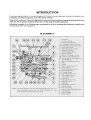
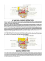
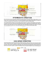
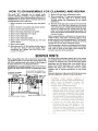
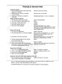
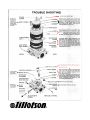
TILLOTSON,
Clash
Industrial
Tralee,
Ireland
County
LTD.
Estate
Kerry
Ref. No. SM/I
Printed
in
U.S.A.
INTRODUCTION
The gasoline engine industry's universal acceptance of Tillotson's original diaphragm carburetor has resulted in the
development, by Tillotson engineers, of the "HL " Series carburetor .
Designedwith a minimum of parts, this lightweight, compact carburetor includes an integral fuel pump and filter in one
small unit. The all position mounting feature allows a wide range of possible applications.
Information contained in the following pages is presented as an aid to understanding construction, operation and
servicing of the "HL " series carburetor.
HL SCHEMATIC
CONSTRUCTION
DATA
The "HL" series carburetor is a lightweight, aluminum die cast carburetor composedof four basic parts: metering
body, main diaphragm cover plate, fuel pump body and strainer cover. The diaphragm carburetor incorporates many
of the same type components found in float type carburetors: choke,throttle, idle and main mixture adjustment screws,
idle speedscrew and inlet needle and seat.
Two styles of main and idle adjustment screwsare available: "0"ringtypeand spring loadedpacking type. Both types
are designed to perform the dual purpose of sealing the metering chamber and providing adjustment screw friction.
A special insert, housedin a brass cage,forms a seat for the inlet needle.An inlet tension spring exerts a pre-determined
force on the inlet control lever which holds the needle on its seat.
A metering diaphragm is subjected to engine suction on the metering chamber side and atmospheric pressureon the
vented side. Atmospheric pressureon the vented side pushesthe diaphragm toward the inlet control lever, openingthe
inlet needle to allow fuel to enter the metering chamber, from which it is then delivered into the mixing passages.
The vented side of the metering diaphragm may be vented either directly to the atmosphere,or in the caseof a balanced
carburetor, may be balanced (internally vented) to the choke bore. The balanced type can berecognizedby a brasstube
in the choke bore which is connectedinternally to the vented side of the diaphragm. The purposeofintemal balanceis
to offset the enriching or choking effect of a partially dirty air cleaner.
Some carburetor metering systems include a ball check type main nozzle. These can be identified by the brass cage
located in the venturi choke band of the body casting. The ball check valve allows fuel to flow into the mixing passage
and prevents air from flowing into the metering chamber.
The movement of the pump diaphragm draws fuel into the fuel chamber and a reverse movement of the diaphragm
forces fuel out of the fuel chamber through the inlet needleand seat into the metering chamber. Movement is causedby
pulsation from the engine, acting on the diaphragm.
A plastic turret type inlet connection is the cover to the fuel strainer section of the carburetor and can be rotated 360
degreesfor any required fqel connection location. The strainer consists of a fine mesh screento insure clean fuel supply
to the metering section of the carburetor .
ADJUSTMENT
INSTRUCTIONS
To properly adjust carburetor for best performance the engine must be thoroughly warm.
INITIAL
ADJUSTMENTS:
To start a cold engine, first carefully close, by turning clockwise, both idle and main adjustment screws. Open main
adjustment screw counterclockwise approximately one and one quarter (114)turns. Open idle adjustment screwthree
quarters (:1;4)
turn. Back idle speedregulating screw off its contact with throttle stop lever, then turn it inward about one
(1) full turn so as to slightly open throttle shutter.
Open fuel line shut off valve, closechoke shutter, partly openthrottle shutter and pull starting cord. When enginefires,
open choke shutter slightly and idle the engine. Do not race engine. Then as engine warms, openchokeshutter. To start
a warm engine it should only be necessary to pull starting cord, if the carburetor is properly adjusted.
FINAL ADJUSTMENTS:
Completely close throttle shutter and readjust idle speedregulating screw so engine idle speedis approximately 1200
RPM for lawn mowers-2000 to 2500 RPM for chain saws-then slowly readjust idle adjustment screw to obtain
smooth and even engine performance. Poor acceleration may result from setting the idle mixture too lean.
DO NOT
FORCE
ADJUSTMENTS
INTO
SEATS!
STARTING
CHOKE
OPERATION
Starting an engine with the "HL" Carburetor involves the same methods that are used in a conventional float feed
carburetor. However, since a diaphragm carburetor doesnot have the advantage of a great reservoir of fuel upon which
to operate, the technique changes somewhat.
When starting a cold engine, place the choke shutter in the closed position and throttle shutter in a cracked or open
position. Several pulls on the starter may be neededto raise the fuel pressureto the required amount. As the engine is
pulled through with the choke in closed position, engine suction will be transmitted to the diaphragm fuel chamber
through both primary and secondary idle discharge parts as well as the main fuel discharge part, creating a low
pressurearea on the fuel side of the main diaphr~gm. Atmospheric air pressureon the oppositeside will forcethe main
diaphragm upward causing the diaphragm button to depressthe inlet control lever, overcoming inlet tension spring
pressure,permitting fuel to enter through the inlet seat, by forcing inlet needle off its seat contact, then into the fuel
chamber side of main diaphragm, up through the idle and main fuel supply orifices and channels, and out the
discharge parts to the engine.
In starting an engine that has been idle and not running for more than an hour, it will be necessaryto operateand
maneuver the choking mechanism for approximately three (3)to ten (10)secondsdepending on how cold the enginehas
become.The length of time spent warming the engine is only necessary to the extent that the engine can be madeto
idle, accelerate and run satisfactorily under wide open throttle conditions;
IDLING
OPERATION
When engine is idling, throttle shutter is in a partially cracked position. Engine suction is transmitted through the
primary idle fuel discharge port to the fuel chamber side of main diaphragm via the idle fuel supply channel. Again, the
main diaphragm is forced upward by atmospheric pressure,depressingthe inlet control lever overcoming inlet tension
spring pressureand permitting fuel to enter through inlet seat, by forcing inlet needleoff its seatcontact, and filling the
fuel chamber side of main diaphragm. The fuel is then drawn up through idle fuel adjustment orifice and deliveredto
the engine through primary idle discharge port.
4
INTERMEDIATE
OPERATION
Fuel is delivered into and through the carburetor in the same manner as when the engine is idling. However, as the
throttle opens and engine speedincreases, more fuel is demanded from the carburetor and supplied to the engine by
valving in the secondary idle discharge port located immediately behind the throttle shutter.
As the throttle shutter continues to open and engine speedincreases, the velocity of air through the venturi createsa
low pressure area at the venturi throat and diminishes the suction on engine side of the throttle shutter. When the
pressure at the venturi throat is less than existing within main diaphragm fuel chamber, fuel is drawn up through
main fuel adjustment orifice and out main fuel discharge port into air stream entering engine intake.
HIGH
SPEED
OPERATION
As the throttle shutter progressively opens from intermediate position to full open position, the air velocity through the
venturi increases and fuel is metered up through main fuel adjustment orifice and main fuel discharge port in
accordance with the power requirements of the engine. The action of the main diaphragm is the same as previously
described with suction required to operate the diaphragm being transmitted through the main fuel discharge port.
SUPPLY
ATMOSPHERIC
PUMP
IMPULSE
AIR
FUEL
FUEL UNDER PRESSURE
AIR
FUEL
5
UNDER VACUUM
HOW
TO
DISASSEMBLE
FC ~R
The model "HL" carbureior can be cleaned under
adverse conditions-workih'g on a clean surlac~with a
minimum of tools. Before disassembling carburetor it is
IMPERATIVE to flush it clean of sawdust and dirt by
pouring gasoline over it and tools.
1. Remove strainer cover retaining screw and plastic
cover.
2. Remove strainer cover gasket and strainer screen.
3. Remove screws and fuel pump body.
4. Removefuel pump diaphragm and gasket.
5. Removemain diaphragm cover plate.
6. Removemain diaphragm.
7. Removemain diaphragm gasket.
8. Remove inlet control lever fulcrum pin, lever and
tension spring.
9. Removeinlet needle.
10. With a thin wall 5/16" Hex socket carefully remove
the inlet seat. Remove inlet seat gasket. When
reinstalling seat, tighten only from 25-35 inchpounds or 34 Kg-Cm.
SERVICE
When reassembling the inlet control lever and spring,
care should be taken to seethat the spring rests in the
well of the metering body and locates on the dimple of
the inlet control lever , (as illustrated below).
CAUTION: Do not stretch spring. Inlet control lever is
properly set when flush with floor of diaphragm chamber.
CLEANING
AND
REPAIR
11. Remove idle and main adjustment screws.
12. When reinstalling "0" ring type adjustment screws,
lubricate with #30 SAE oil to prevent seizing.
Packing spring type adjustments do not require
lubrication.
13. The ball check type main nozzle can be removed by
tapping it out of the body casting into the venturi
with a small punch. A replacement ball checknozzle
should be pressed into the casting with the cross
holes in line with the main adjustment needle.The
brass cageshould be pressedflush with the metering
chamber casting.
Before reassembling the carburetor (in reverse order as
outlined above), wash ALL component parts in clean
gasoline and blow off with compressedair. The channels
in the metering body should be cleaned by blowing
through the idle and main adjusting orifices.
All fuel passagesin the three castings should be cleaned
with compressedair. Do not clean orifices or passages
with wires or drills as this might cause damage and
incorrect operation of the carburetor.
HINTS
Be certain main diaphragm, gasket and cover casting
are carefully fitted over the three small pins cast in rim
at bottom of metering body; also the fuel pump gasket,
diaphragm and fuel pump body, over similar pins at
bottom rim of main diaphragm cover casting. Evenly
tighten fuel pump body retaining screws to insure
complete seal of casting separations at both diaphragms.
Frequent cleaning or replacemnet of fuel strainer screen
will aid satisfactory operation of the carburetor .
CAUTION: Under extreme conditions of
clogged idle fuel supply channel and discharge
ports, it may be necessary to remove the
channel welch plug. If so, it must be very
carefully done in following manner:
1. Drill a 1111"
diameter hole through the :VII"
diameter welch plug. This hole should just
break through the welch plug. Deeper drilling will seriously damage the body casting
and its discharge ports located close behind
the welch plug. C)nsomemodels an additional smaller 1;4"diameter channel welch plug is
used. It is not necessaryto removethis plug.
2. Carefully pry out welch plug, then clean
discharge ports and cross channels. Now
install new part 02531 (:VII"diameter, 1132"
thick) welch plug by placing it in casting
shoulder, convexed side upward; then flatten
to a tight fit with a 5116" diameter flat end
tool.
~
TROUBLE
,
Carburetor Floods
1. Dirt or foreign particles
needle from seating.
preventing
2. Diaphragm lever spring
on lever dimple.
3. Diaphragm
carburetor.
improperly
SHOOTING
inlet
Remove, clean and replace
not seated
installed
Remove lever and reinstall
in
Replace diaphragm
or correct
installation
Engine will Not Accelerate
1. Idle adjusting
2. Incorrect
screw set too lean.
setting
Enrich idle adjustment
lever.
Reset
3. Diaphragm
cover plate loose.
Tighten
4. Diaphragm
gasket leaking.
Replace
Remove diaphragm cover, diaphragm lever and main adjusting screw. Clean
out orifice by blowing through main adjustment threaded hole.
5. Main fuel orifice
Engine
Will
Reset to best idle
idle adjustment.
2. Idle discharge
3.
plugged.
Not Idle
1. Incorrect
~
on diaphragm
Diaphragm
ports
lever
set
or channels
Blowout
with compressed air, or, if compressed air is not available, clean and
flush with gasoline.
clogged
Reset daiphragm.lever
so it is flush with
the floor of the diaphragm chamber.
Reset
incorrectly.
4. Throttle shutter cocked
bore causing fast idle.
in the throttle
5. Dirty nozzle check valve.
Clean or replace
6. Welch plug covering the idle discharge
ports does not seal. This causes the engine
to idle with idle adjustment shut off.
Replace welch plug, following
outlined in service hints.
Engine
Runs
Out
1. Tank
vent
2. Leak
in fuel
system
fuel
4. Main
orifice
fuel
Carburetor
Lean
not operating
3. Ruptured
Runs
pump
from
Clean, if possible,
correctly.
tank
Tighten
to pump.
diaphragm.
Rich
With
Main
NOTE: IN MAKING
Set engine
CARBURETOR
or replace
or replace fittings
or line
Replace
Clean
plugged
Adjustment
Shut
1. The Vs" diameter
nozzle channel
plug, or
nozzle check valve cage, is not sealing.
GENTLY-DO
instructions
ADJUSTMENTS
NOT RAM ADJUSTMENTS
idling speed in accordance
Off
Install
new plug
or new cage
TURN ADJUSTMENTS
CAREFULL Y AND
INTO SEATS.
with engine
manufacturer's
recommendation.
TROUBLE
SHOOTING
lei Inlet Line must be tight
COV~R
Be sure all
SCREW
CO
ER
V
Pump Body
Screws are
tighttoinsure--BODY
perfect seal
at the parting
surfaces.
Remove
)
GASKET
SCREW
Cover
SCREEN
-place
bcrew,
Thoroughly
gasoline
-I
~
screen.
or
by
Cover,
clean
blowing
t2asket
Screen
through
and
with
clean
with
com-
pressed air. Install Screen next to Pump
Body casting, then gasket. Hold Cover in
and tighten Cover Screw.
PUMP BODY
Pump Gasket and Pump Diaphragm must
locate on cast pins, at underside of DiaCover rim, to insure correct installation and operation. Pump Diaphragm must
be clean and free of breaks or punctures.
PUMP
A TMOSPHERIC
VENT---
DIAPHRAGM
Diaphragm
COVER\
MAIN
DIAPHRAGM~
IDLE SPEED
REG. SCREW
DIAPHRAGM'
GASKET
-INLET
CONTROL
SPRING
--i
NEEDLE.
INLET SEAT~
PLUG
METERING
CHAMBER
.--~
i
~~ --INSERTA
(
CHOKE SHAFT
FRICTION PIN
/
SPRING ~
Drain Plug
Screw must
seal tightly.
Main
Diaphragm
and
BODY
SPRING
Press in place
flush with
-BRASS
body casting.
Gasket,
Diaphragm
Cover Casting, must locate on
cast pins, at the body rim, to insure cor.rect installation
and operation.
Main Dia!phragm must be clean and free of breaks
or punctures. Its metal disc must not become
bent and should always retain tight fit to
rubberized body section.
~
."i;
T..~
:
GASKET'
.
WELCH
PLUG
OISCHARGE
PORTS
~- PLUG
SCREW.
,
PACKING.
.FULCRUM
PIN
WASHER-
ADJUSTMENT
SCREW
To inspect
an(j clean Inlet Nee(jle
ana
Seat, first remove Fulcrum Pin an(j Control
Lever, then inlet needle, The Inlet Seat
can now be carefully
removed
with
a
5/16" hex socket wrench.
CAUTION'
If Inlet Seat is not handled with
,.care the small Insert may fall out unnoticed.
Remove Gasket and replace with new one
before
reinstalling
Inlet Needle and Seat
by reversing above procedure.
IMPULSE
CHANNEL
Welch Plug must seal tightly.
ldle Discharge Ports must be open.