1
VF5000 series high capacity vector control inverter service manual
Foreword
Thank you for purchasing VF5000 series high capacity vector control inverter
from our company Pioneer Electronics CO., LTD.
VF5000 series can fulfill all kinds of demand for general-purpose inverter by
advanced control manner which make high torque, high precision and wide-range
speed regulation drive be available. VF5000 is organic combine of customer’s
general need and industrial requirement to provide practical PI adjuster, simple PLC,
programmable input output terminal control, long-distance synchronous control,
impulse frequency provision and other special inverter control with powerful
function for customer and to provide highly-integrated incorporative solution of high
value for reducing system cost and improving system reliability for device
manufacturing and automation engineering customers.
VF5000’s big torque low noise and low electromagnetic disturbance during
operation can fulfill customer’s environmental protection requirement by space
voltage vector control technology and electromagnetic compatibility unitary design.
Assembling wiring, parameter setting, troubleshooting and daily maintenance
notice are available in this manual. To make sure that you can correctly assemble
and operate VF5000 series inverters to exert their excellent performance, please read
this user manual detailedly before you assemble the device and conserve the manual
appropriately before the end-user get them.
Please contact our office or dealer in all places at any moment if you have any
doubts or special demands when using these inverters, and you can also contact our
after service center in our Headquarters directly. We will serve you with all our
heart.
We reserve our right to notice you if we change contents or this manual.
-1-
VF5000 series high capacity vector control inverter service manual
Contents
1
Summary
1.1 Confirmation of product---------------------------------------------------------(4)
1.2 Safety attentions------------------------------------------------------------------(5)
1.3 Use attentions ---------------------------------------------------------------------(7)
1.4 Rejection attentions---------------------------------------------------------------(8)
2
Product specification and order notification
2.1 Inverter series model-------------------------------------------------------------(9)
2.2 Specifications--------------------------------------------------------------------(10)
2.3 Outline size-----------------------------------------------------------------------(12)
2.4 Option-----------------------------------------------------------------------------(17)
3
Installation and wiring of inverter
3.1 Installation environment of inverter------------------------------------------(19)
3.2 Disassembling and installing of inverter keypad----------------------------(20)
3.3 Attentions of inverter wiring---------------------------------------------------(20)
3.4 Wiring of main circuit terminal------------------------------------------------(21)
3.5 Diagram of wiring for basic running-----------------------------------------(24)
3.6 Control circuit configuration and wiring-------------------------------------(25)
3.7 Installation guide in line with EMC requirement---------------------------(28)
4
Running and operation of inverter
4.1 Running of inverter-------------------------------------------------------------(31)
4.2 Operation and using of keypad------------------------------------------------(32)
5
Specification of function parameter table
5.1 Basic parameter:(F0.00-F0.23)----------------------------------------------(40)
5.2 Motor and vector control parameter group:(F1.00-F1.15)---------------(45)
5.3 Auxiliary parameter group:(F2.00-F2.43)---------------------------------(47)
5.4 User’s management parameter group:(F3.00-F3.09)---------------------(54)
5.5 Digital input and output parameter group:(F4.00-F4.16)----------------(56)
5.6 Analog input output parameter group:(F5.00-F5.16)---------------------(61)
5.7 PID control parameter group:(F6.00-F6.14)-------------------------------(65)
5.8 Programmable running parameter group:(F7.00-F7.18)-----------------(67)
5.9 Communication parameter group:(F8.00-F8.04)--------------------------(70)
5.10 Protection function parameter:(F9.00-F9.03)----------------------------(72)
5.11 Advanced function parameter:(FA.00-FA.12)----------------------------(72)
6
Function parameter table
6.1 Function parameter schedule graph(F0.00-FA.12)-----------------------(74)
-2-
VF5000 series high capacity vector control inverter service manual
6.2 Supervision function(D-00-D-28)-------------------------------------------(87)
7
Troubleshooting
7.1 Failure and countermeasure----------------------------------------------------(89)
7.2 Enquiry of fault record---------------------------------------------------------(91)
7.3 Fault reset------------------------------------------------------------------------(91)
8
Maintenance
8.1 Maintenance----------------------------------------------------------------------(92)
8.2 Regular inspection--------------------------------------------------------------(92)
8.3 Warranty of inverter-------------------------------------------------------------(93)
-3-
VF5000 series high capacity vector control inverter service manual
1 Summary
1.1 Confirmation of product
After uppacking, please check whether the inverter is scratched or damaged in
course of carrying, and whether the rated value on the nameplate is in line with your
order requirement.
If finding any problems, please contact supplier or us.
Model description:
VF5000 – C 4 T 1P5 G B
B
Built-in brake unit
Inverter serial no.
BR
Built-in brake resistance
Type
Code
Inverter type
G
General
P
Special
Code
Motor power
1P5
1.5KW
Volt. grade
Code
220V
2
380V
4
Input volt.
Code
7P5
7.5KW
Single phase
D
18P5
18.5KW
Three phase
T
110P
110KW
Fig.1-1 Model description
There is a nameplate with inverter model and rated value stuck on the lower
part of right plate of inverter case, the information in it as follows:
Fig. 1-2 Nameplate of inverter
-4-
VF5000 series high capacity vector control inverter service manual
1.2 Safety attentions
RECEIVING
CAUTION
1. Do not install or operate any inverter which is damaged or
has missing parts.
Failure to observe this caution may result in personal injury or
equipment damage.
INSTALLATION
CAUTION
1. Lift the cabinet by the base. When moving the unit, never
lift by the front vover.
Otherwise, the main unit may be dropped causing damage to the
unit.
2. Mount the inverter on nonflammable material.
Failure to observe this caution can result in a fire.
3. When mounting units in an enclosure, install a fan or other
colling device to keep the intake air temperature below 45℃.
Overheating may cause a fire or damage to the unit.
WIRING
WARNING
1. Only commence wiring after verifying that the power
supply is turned OFF
Failure to observe this warning can result in an electrical shock or
a fire.
2. Wiring should be performed only by qralified personnel.
Failure to observe this warning can result in an electrical shock or
a fire.
3. When wiring the emergency stop circuit, check the wiring
-5-
VF5000 series high capacity vector control inverter service manual
thoroughly before operation.
Failure to observe this warning can result in personal injury.
CAUTION
1. Verify that the inverter rated voltage coincides with the AC
power supply voltage.
Failure to observe this canution can result in personal injury or a
fire.
2. Do not perform a withstand voltage test of the inverter.
It may cause semi-conductor elements to be damaged.
3. Tighten terminal screws to the specified tightening torque.
Failure to observe this caution can result in a fire.
4. Never connect the AC main circuit power supply to output
terminals U, V and W.
The inverter will be damaged and invalidate the guarantee.
OPERATION
CAUTION
1. Never touch the heatsink or discharging resistor since the
temperature is very high.
Failure to observe this caution can result in harmful burns to the
body.
2. Since it is easy to change operation speed from low to high
speed, verify the safe working range of the motor and
machine befor operation.
Failure to observe this caution can result in personal injury and
machine damage.
3. Install a holding brake separately if necessary.
Failure to observe this caution can result in personal injury.
MAINTENANCE AND INSPECTION
-6-
VF5000 series high capacity vector control inverter service manual
WARNING
1. Never touch high-voltage termainals in the inverter.
Failure to observe this warning can result in an electrical shock.
2. Replace all protective covers before powering up the
inverter. To remove the cover, make sure to shut OFF the
molded-case circuit breaker.
Failure to observe this warning can result in an electrical shock.
3. Perform maintenance or inspection only after verifying that
the CHARGE LED goes OFF, after the main circuit power
supply is turned OFF.
The capacitors are still charged and can be dangerous.
4. Only authorized personnel should be permitted to perform
maintenance, inspections or parts replacement.
[Remove all metal objects (watches, bracelets, etc.) before
operation]
Failure to observe this warning can result in an electrical shock.
CAUTION
1. The control PC board employs CMOS ICs. Do not touch the
CMOS elements.
They are easily damaged by static electricity.
2. Do not control or disconnect wires or connectors while
power is applied to the circuit.
Failure to observe this warning can result in personal injury.
1.3 Use attentions
Please pay attention following points when using VF5000.
1. VF5000 series inverter is voltage-type inverter, so temperature, noise and
vibration slightly increasing compared to power source running when using, belongs
to normal phenomenon.
2. If need to run for a long time with constant torque of low-speed, must select
motor of frequency conversion for use. Use general asynchronous AC motor when
running at a low speed, should control temperature of the motor or carry on heat
-7-
VF5000 series high capacity vector control inverter service manual
dissipation measure forcedly, so as not to burn the generator.
3. Such mechanical device needing lubricating as the gearbox and gear wheel, etc.,
after running at a low speed for a long time, may be damaged as lubrication result
become poor, please take necessary measure in advance.
4. When the motor running with frequency above specified, besides considering the
vibration, noise increase of the motor, must also confirm speed range of the motor
bearing and the mechanical device.
5. Fof hoist and great inertia load, etc., the inverter would shut off firequentl due to
over-current or over-voltage failure, in order to guarantee normal work, should
consider choosing proper brake package.
6. Should switch on/off the inverter through terminal or other normal order channels.
It is prohibited that switch on/off the inverter frequently by using shrong electric
switch such as magnetic control conductor, otherwise will cause the equipment to be
damaged.
7. If need to install such switch as the magnetic control conduct, etc., between
inverter output and the motor, please guarantee the inverter is switched on/off
without output, otherwise may damage the inverter.
8. The inverter may meet with mechanical resonance of the load within certain range
of frequency output, can set up jumping frequency to evade.
9. Before using, should confirm the voltage of the power is within the working
voltage range allowed, otherwise should vary voltage or order special inverter.
10. In the condition of altitude above 1000meters, should use the inverter in lower
volume, reduce output current by 10% of specified current after each 1500meters
height increasing.
11. Should make insulation check to the motor before using it for the first time or
after a long time placement.
12. To forbid assembling capacitor for improving power factor or lightningproof
voltage-sensible resistance etc., otherwise will cause malfunction trip of the inverter
or damage of the parts.
1.4 Rejection attentions
When disposing scrap inverter and its parts, please note:
1. The unit: please discard as industrial useless.
2. Electrolytic capacitor: when burning the inverter electrolytic capacitor in it may
explode.
3. Plastic: when plastic, rubber parts etc. in the inverter are burning , they may bring
bad, poisonous gas, so please be ready to safeguards.
-8-
VF5000 series high capacity vector control inverter service manual
2
Product specification and order notification
2.1 Inverter series model
VF5000 series inverter has two voltage classes: 220V and 380V. The applicable
motor power range is 0.75KW~315KW. VF5000 series inverter model is shown as
table2-1.
Table 2-1 Model of VF5000 series inverter
Voltage class
380V
220V
Model
Rated power
(KVA)
Rate output
current(A)
Adapted motor
(KW)
VF5000-C4T0P7G
1.5
2.1
0.75
VF5000-C4T1P5G
3.7
3.7
1.5
VF5000-C4T2P2G
4.7
5.0
2.2
VF5000-C4T4P0G
6.1
8.8
4.0
VF5000-C4T5P5G
11
12.0
5.5
VF5000-C4T7P5G/P
14
16.0
7.5
VF5000-C4T11PG/P
21
23.0
11
VF5000-C4T15PG/P
26
31.0
15
VF5000-C4T18P5G/P
31
36.0
18.5
VF5000-C4T22PG/P
37
43.0
22
VF5000-C4T30PG/P
50
58.0
30
VF5000-C4T37PG/P
61
70.0
37
VF5000-C4T45PG/P
73
85.0
45
VF5000-C4T55PG/P
98
103.0
55
VF5000-C4T75PG/P
130
145.0
75
VF5000-C4T90PG/P
170
170.0
90
VF5000-C4T110PG/P
138
201.0
110
VF5000-C4T132PG/P
167
240.0
132
VF5000-C4T160PG/P
230
305.0
160
VF5000-C4T200PG/P
/PVF5000-C4T1600M
VF5000-C4T220PG/P
250
380.0
200
280
415.0
220
VF5000-C4T245PG/P
340
475.0
245
VF5000-C4T280PG/P
450
505.0
280
VF5000-C4T315PG/P
460
580
315
VF5000-C2D0P7G
1.4
4.5
0.75
VF5000-C2D1P5G
2.6
7.0
1.5
-9-
VF5000 series high capacity vector control inverter service manual
VF5000-C2D2P2G
3.8
10.0
2.2
2.2 Specifications
Item
Item description
Rating volt. frequency Single phase 220V、3 phase 220V、3 phase 380V;50Hz/60Hz
Input
Output
Main
control
Variable allowable
value
Voltage:-20% ~ +20%
Voltage unbalance:<3% Frequency:±5%
Voltage
0~220V/0~380V
Frequency
0Hz~400Hz
Overload capacity
150% 1min,180% 1s,200% instant protection;
Control mode
Space voltage vector PWM control (With superior
low-frequency dead zone compensation characteristic)
Frequency precision
Digital setting:Max frequency×±0. 01%;
analog setting:Max frequency×±0.2%
Frequency resolution
Digital setting:0.01Hz;analog setting:Max frequency×0.1%
Start-up frequency
0.0Hz~10.00Hz
Torque boost
Automatic torque boost,manual torque boost1%~30.0%
V/F curve
Three ways: line V/F cruve, square V/F curve, user
self-defining V/F curve.
Acceleration/deceler
ation time
Optional time unit (Min/s), max 3600s(0.1~3600s)
DC braking
Optional start-up and stop, action frequency0~20Hz,action
volt. 0~20%,action time 0~30s
Jog
Jog frequency range:0.1Hz~50.00Hz,jog accelerating
decelerating time 0.1~3600s
Interior PID
Be convenient to make closed-loop system.
Multi-speed running
Realized by interior PLC or control terminal
Weaving traverse
frequency
Can get traverse frequency of adjustable central frequency.
Automatic voltage
regulation
Can keep constant output voltage when power source voltage
varies.
Automatic energy
save running
Optimize V/F curve automatically based on the load to realize
power save running.
Automatic current
limiting
Limit running cuttent automatically to avoid frequent
over-cuttent which will cause trip
function
- 10 -
VF5000 series high capacity vector control inverter service manual
Running command
passage
Setting of operating manual; setting of control terminal;
setting of serial port; switching by three ways.
Frequency setting
passage
Setting of keypad analog potentiometer; setting of
keypad▲
▲、▼keys. Setting of functional code digits. Setting
of serial port, setting of terminal UP/DOWN, setting of
analog voltage, setting of analog current; settting of
impulse, setting of combination; switching at any time by
kinds of settting ways.
Switch input passage
Forward/reverse rotating command, 6-way programmable
switching value input to set 21 functions.
Analog input passage
2-way analog signal input,0~20mA、0~10V optional.
Analog output
channel
Analog signal output 0~10V to get output of physical
quantity like frequency and output frequency.
Switch output
passage
2-way programmable open collector output; 1-way relay
output signal, to get output of different physical quantities.
LED display
Can display setting frequency、output voltage、output current
etc.
Display external
instrument
Display output frequency, output current, and output voltage
and so on.
Running
Keypad
Protection function
Option
Environ
ment
Structure
Over cuttent protection, over voltage protection, under
voltage, over-heat protection, over-load protection, missing
phase protection (in option) etc.
Brake subassembly, remote-control keypad, connecting cable
for remote-control keypad etc.
Use ambient
Indoor, not bare to sunlight, no dust, no corrosive gas, no
flammable gas, no oil fog, no vapor, no water drop or salt
etc.
Altitude
Lower than 1000m
Temperature
-10℃~+40℃
Humidity
Smaller than 90%RH,no condensation water
Vibration
Smaller than 5.9m/s2
Storage temperature
-20℃~+60℃
Defending frade
IP20
Cooling mode
By fan
Mountion mode
Wall hanging
- 11 -
VF5000 series high capacity vector control inverter service manual
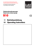
2.3 Outline size VF2100/VF3000/VF5000(unit:mm)
(a):0.4KW~1.5KW-M size
(b):0.75KW-2.2KW size
(c):4.0KW-5.5KW size
(d)
:7.5KW~15KW size
- 12 -
VF5000 series high capacity vector control inverter service manual
(e)
:18.5KW~75kW
- 13 -
VF5000 series high capacity vector control inverter service manual
(f)
:90KW~150KW
- 14 -
VF5000 series high capacity vector control inverter service manual
(g):160KW~200KW
- 15 -
VF5000 series high capacity vector control inverter service manual
(h):220KW~315KW
Table 2-2 inverter outline & installation size
Type
VF5000M-C4T0P7G
VF5000M-C4T1P5G
H
A
140
84
170
250
A1
D
D1
B
W
110
129
73
125
138
159
114
153
185
236.5
142
VF5000-C4T0P7G
VF5000-C4T1P5G
VF5000-C4T2P2G
VF5000-C4T4P0G
VF5000-C4T5P5G
- 16 -
VF5000 series high capacity vector control inverter service manual
VF5000-C4T7P5G/P
VF5000-C4T11PG/P
310
205
185
300
192
450
280
201
235
40
435
160
575
335
220
250
40
555
180
615
375
270
265
40
595
230
720
410
258
310
40
705
260
820
485
350
800
345
1525
500
415
1735
845
470
VF5000-C4T15PG/P
VF5000-C4T18P5G/P
VF5000-C4T22PG/P
VF5000-C4T30PG/P
VF5000-C4T37PG/P
VF5000-C4T45PG/P
VF5000-C4T55PG/P
VF5000-C4T75PG/P
VF5000-C4T90PG/P
VF5000-C4T110PG/P
VF5000-C4T132PG/P
VF5000-C4T150PG/P
VF5000-C4T160PG/P
VF5000-C4T185PG/P
400
VF5000-C4T200PG/P
VF5000-C4T220PG/P
VF5000-C4T250PG/P
VF5000-C4T280PG/P
VF5000-C4T315PG/P
VF5000-LC04/LC03 outer size
VF5000-LC04/LC03 hole size
Table 2-3 Remote-control keypad size
2.4 Option: following options please order separately.
2.4.1 Remote-control keypad
Between VF5000 inverter and its remote-control keypad are provided with RS485
- 17 -
VF5000 series high capacity vector control inverter service manual
communication way and connected by one 10-core network cable, the connection of
port is provided with RJ45 network interface connection, it is very convenient to
install. The max electric distance can reach as high as 500m.
The remote-control keypad has following functions:
1. Can control the running, stopping, jogging, fault resetting, change of setting
frequency, change of function parameter and running direction of slave.
2. Can monitor operating frequency, setting frequency, output voltage, output current
and so on.
2.4.2 Communication cable
Communication cable of remote-control keypad
Model: VF5000-LAN0020 (2.0m)
Among the specifications, 1m, 2m, 5m, 10m and 20m are our inverter standard
configuration, if need over 20m, user can contact us.
Be used for connection between remote operating keypad and master of
inverter.
2.4.2 Braking resistor
VF5000 series inverter braking unit is option, if need, please indicate clearly
when ordering. Energy-consumption braking resistor is provided as shown in
table2-4.
Table 2-4 Selectable table of braking resistor
Applicable motor
Resistor
Resistor Power
Model No.
Power(KW)
Resistance(Ω)
(W)
VF5000-C4T0P7G
0.75
400
100
VF5000-C4T1P5G
1.5
300
200
VF5000-C4T2P2G
2.2
200
200
VF5000-C4T4P0G
4.0
150
400
VF5000-C4T5P5G
5.5
100
500
VF5000-C47P5G
7.5
75
600
VF5000-C4T11PG
11
60
800
VF5000-C4T15PG
15
45
1200
VF5000-C4T18P5G
18.5
38
1500
VF5000-C422PG
22
34
1500
VF5000-C4T30PG
30
25
2500
VF5000-C4T37PG
37
18
3000
- 18 -
VF5000 series high capacity vector control inverter service manual
3 Installation and wiring of inverter
3.1 installation environment of inverter
3.11 installation environment condition
1. The inverter shall be installed indoors of perfect ventilation, and the environment
temperature shall be in the range of -10℃~40℃,in case that temperature exceeds
40℃,the external air-blast cooling or derating shall be used.
2. Avoid being installed in the location where suffers from the sun, dust, floatation
fiber and metallic powder.
3. Never to be installed in the location where corrosive and explosive gas has.
4. The humidity shall be lower than 95%RH, no condensation.
5. The inverter had better be kept far sway the electromagnetic interference device.
3.12 installation direction and space
1. Shall be installed vertically usually.
2. The installation space and min distance are shown as diagram 3-1.
3. As is shown in diagram 3-2, there shall be a baffler mounted among them, when
several inverters are installed vertically.
Cooling fan
VF5000
Baffler
VF5000
Diagram 3-1 Installation space
Diagram 3-2 Installation of multi inverters
- 19 -
VF5000 series high capacity vector control inverter service manual
3.2 Disassembling and installing of inverter keypad
Disassemble: Remove two screws on the side of connection terminal with the
cross screwdriver, i.e., the enclosure can be disassembled.
Install: Align the mounting screw, and then mount the screw.
3.3 Attentions of wiring
CAUTION
(1) Before connecting, make sure the power supply has been cut off for more
than 10min, otherwise, there would be electric shock danger.
(2) Never to connect the power line to output terminals U, V, W of inverter.
(3) Because there is leakage current in the inverter, the inverter and motor must
be grounded safely, the grounding wire shall be copper conductor of more
than 3.5mm², and the grounding resistance shall be less than 10Ω.
(4) User shall not conduct the withstand voltage test for the inverter as it has
passed this test before leaving factory.
(5) Between inverter and motor shall not be installed with the electromagnetic
contactor and absorbing capacitor or other resistance-capacitance
absorbing implements as diagram 3-3.
(6) To take the convenience for over current protection of input side and power
failure maintenance, the inverter shall be connected to power supply
through intermediate breaker.
(7) The connecting wire(X1~X6、D01、A0V)of input and output circuit of relay
shall be the stranded wire or shielded wire of over 0.75mm², one end of
shielded layer shall be hung in the air, and the other is connected with the
earthing terminal E of inverter, the connecting wire shall be less than 50m.
DANGER
(1) Make sure the power supply of inverter has been cut off thoroughly, all
LED lamps of keyboard has went out, and wait for more than 10min,can
perform the wiring operation.
(2) Make sure that DC voltage between main circuit terminals P+ and N- of
inverter steps down to DC36V below, till now, start to perform the wiring
- 20 -
VF5000 series high capacity vector control inverter service manual
operation.
(3) Only the qualified professional who has been trained and authorized can
perform the wiring operation.
(4) Please pay attention that before energizing, check whether the voltage class of
inverter is identical with the supply voltage, otherwise, it would result in person
casualty and damage of device.
3.4 Wiring of main circuit terminal
VF5000
Breaker
AC
power
R(L)
U
V
W
E
S
T(N)
M
Diagram3-3 Simple wiring of main circuit
3.4.1 Connection of inverter and option
1. Between power grid and inverter,
breaking equipment like isolating switch
shall be installed for human safety and
compulsive power cutting during
maintaining the device.
2. The supply circuit of inverter must be
mounted with the fuse or circuit breaker
with over current protection, to avoid the
spread of fault.
3. When the power supply quality of power
grid is not quite high, an AC input reactor
shall be mounted additionally. The AC
reactor also can improve the power factor
of input side.
4. The contactor is only for control of power
supply.
5. EMI filter on the input side
The EMI filter can be used to prevent
High-frequency conductivity interference
And radio-frequency interference from the
inverter power line.
- 21 -
R
S
T
N
Isolation
switch
Breaker
AC input reactor(optional)
Contactor
Input EMI filter
R S T
VF5000
U VW
E
Output EMI filter
AC output reactor
M
VF5000 series high capacity vector control inverter service manual
6. EMI filter on the output side
The EMI filter can be used to preventradio-frequency interference noise from output
side of inverter and leakage current from conductor.
7) AC output reactor
When the wire connecting inverter to motor is more than 50m, AC output reactor
had better be mounted the leakage current and prolong the service life of motor.
When installing, please consider the voltage drop problem of AC output reactor;
or the input/output voltage of inverter is stepped up or the motor is derated to
protect the motor.
8. Safe grounding wire
The inverter and motor must be earthed separately for safety as there is leakage
current in the inverter; the grounding resistance shall be less than 10Ω.The
grounding wire shall be as short as possible, and its diameter shall be in line with
the standard given in table 3-1.
(Only two kinds of conductors are provided with the same metal, the value table can
be correct, if not, the sectional area of protective conductor is determined with the
equivalent conductive factor method and referred to table 3-1.)
Table 3-1 Sectional area of protective conductor
Corresponding
conductor sectional area(mm2)
Min sectional area of corresponding
grounding conductor (mm2)
S ≤ 16
S
16 < S ≤ 35
16
35 < S
S/2
3.4.2 Wiring of main circuit terminal
1. Input/output terminal of main circuit shown as table 3-2
Table 3-2 Description of input/output terminal
Applicable
machine
Terminal of main circuit
Terminal
name
Function description
L、N
Single phase AC 220V input
U、V、W Three-phase AC 380V output
VF5000-C2D0P7G
~
- 22 -
VF5000 series high capacity vector control inverter service manual
B1、B2
VF5000-C2D2P2G
Braking resistor
R、S、T Three-phase AC 380V output
VF5000-C4T0P7G
VF5000-C4T15PG
U、V、W Three-phase AC 380V output
B1、B2
Braking resistor
R、S、T Three-phase AC 380V input
VF5000-C4T18P5
U、V、W Three-phase AC 380V output
G/P~
VF5000-C4T185P
+、-
G/P
E
VF5000-C4T200P
R、S、T
G/P
VF5000-C4T315P
G/P
Braking resistor
Earthing terminal
Three-phase AC 380V input
U、V、W Three-phase AC 380V output
E
Earthing terminal
2. The specification of Main circuit cable date, inlet protective circuit breaker QF of
fuse as follows:
Output
Control
Breaker
Fuse
Input wire
Type
wire
wire
2
(A)
(A)
(mm )
(mm2) (mm2)
VF5000-C4T0P7G
10
10
1.5
1.5
1
VF5000-C4T1P5G
10
10
1.5
1.5
1
VF5000-C4T2P2G
16
10
2.5
2.5
1
VF5000-C4T4P0G
20
16
2.5
2.5
1
VF5000-C4T5P5G
32
20
4
4
1
VF5000-C4T7P5G/P
40
32
6
6
1
VF5000-C4T11PG/P
63
35
6
6
1
VF5000-C4T15PG/P
63
50
6
6
1
VF5000-C4T18P5G/P
100
63
10
10
1
VF5000-C4T22PG/P
100
80
16
16
1
VF5000-C4T30PG/P
125
100
25
25
1
VF5000-C4T37PG/P
160
125
25
25
1
VF5000-C4T45PG/P
200
160
35
35
1
- 23 -
VF5000 series high capacity vector control inverter service manual
VF5000-C4T55PG/P
200
160
35
35
1
VF5000-C4T75PG/P
250
200
70
70
1
VF5000-C4T90PG/P
315
250
70
70
1
VF5000-C4T110PG/P
400
315
95
95
1
VF5000-C4T132PG/P
400
400
150
150
1
VF5000-C4T160PG/P
630
450
185
185
1
VF5000-C4T200PG/P
630
560
240
240
1
VF5000-C4T220PG/P
270
270
1
800
630
VF5000-C4T245PG/P
800
630
270
270
1
VF5000-C4T280PG/P
1000
800
150×2
150×2
1
3.5 Diagram of wiring for basic running
Diagram 3-5 diagram of wiring for basic running. Applicable
inverter :VF5000-C4T0P7G~VF5000-C4T15PG/P
- 24 -
VF5000 series high capacity vector control inverter service manual
Diagram 3-6 diagram of wiring for basic running. Applicable
inverter :VF5000-C4T18P5G/P~VF5000-C4T315PG/P
3.6 Control circuit configuration and wiring
3.6.1 Layout of control circuit terminal as follows:
Diagram 3-7 Diagram of control panel terminals arrangement
3.6.2 Description of control circuit terminal function shown as table3-4
Type
Communi
cation
Terminal
no.
485+
485-
Name
Terminal function
Spec.
RS485
communication
interface
RS485 differential signal
positive terminal
RS485 differential signal
negative terminal
Standard RS485
communication interfaces
and twisted pair line or
shielded line
- 25 -
VF5000 series high capacity vector control inverter service manual
Programmable multi-function Optic-coupling isolation
digital output terminal is
output. Working voltage:
Multi-func
referred to the introduction 9~30V. Max output current:
Open collector
tion output Y1.Y2
about output terminal function
50mA. Refer to
output terminal 1
terminal
of terminal function parameter.
F4.07-F4.08 parameter
F4.07-F4.08 in chapter 5
description for using
(Common terminal: COM)
methods.
Relay
Normal: TB-TC NC; TA-TC
Rating of contact
TA.TB.T
Fault relay
output
NO
NO:5A 250VAC
C
terminal
terminal
Fault: TB-TC NO;TA-TC NC
NC:3A 250VAC
VCI
Analog
input
CCI
Analog
output
AOI,
AOV
DO1
Running
control
terminal
FWD
REV
X1
X2
Multi-func
tion input
terminal
X3
X4
X5
X6
Power
10V
Analog input VCI
Accept input of analog
Input voltage range:0~10V
voltage.
(input impendence:47KΩ)
(Reference ground:GND)
Resolution:1/1000
Accept input of analog
current and voltage
(Reference ground: GND),
Analog input CCI
diagram 3-9 is referred, select
by dip switch on the left side
of control terminal.
Provide analog voltage or
current output, can express 7
Analog output
analog quantity, indicate the
AOV, AOI
default of motor rotation
speed.
Forward running
Forward /reverse digital
order
command, is referred to
introduction of function
Reverse running
parameter two-wire and
order
three-wire control function
Mu1ti-function input
terminal1
Mu1ti-function input
Programmable multi-function
terminal 2
digital output terminal is
Mu1ti-function input
referred to introduction about
terminal 3
output terminal function of
Mu1ti-function input
terminal function parameter
terminal 4
(Digital input/output).
Mu1ti-function input
(Common terminal: COM)
terminal 5
Mu1ti-function input
terminal 6
+10V power
Provide +10v power supply
- 26 -
Input current range:
0~20mA (input
impendence:500Ω)
Resolution:1/1000
Voltage output range::
0~10V
Current output range:
0~20mA
Optic-coupling isolation
input
Input impendence:
R=2KΩ
Max input Freq.: 200Hz
Input voltage:9~30V
Closing avaiable
X1~X6
FWD、REV
COM
Max input Freq.: 20KHz
Max output current: 50mA
VF5000 series high capacity vector control inverter service manual
GND
COM
+10Vpower
common terminal
+24V power
common terminal
for external.(Negative end:
GND)
Analog signal and reference Mutual inner isolation shall
group of +10V power supply be produced between COM
Input/output common
and GND
terminal of digital signal
Table 3-4 control plate CN3 terminal function
3.6.3 Wiring of analog input/output terminal
(1) VCI terminal accepting input of analog voltage signal, its wiring as follows:
VF5000
10V
F0.01=4
+
―
VCI
0~+10V
GND
E
Diagram 3-8 VCI terminal wiring
(2) CCI terminal accepting input of analog current and voltage signal, its wiring as
follows:
CCI-I
F0.01=5
+
―
10V
VF5000
CCI
0~20mA
JP1
GND
Grounding of shielded
wire near
E
Diagram 3-9 CCI terminal wiring CCI-V
(3) Wiring of analog output terminal AOV、AOI
Analog output terminal AOV 、 AOI with peripheric analog meter can indicate
different physical quantities(F5.09),its wiring is shown as diagram 3-10.
- 27 -
VF5000 series high capacity vector control inverter service manual
Analog meter0-10V
VF5000 AOV
Analog Voltage 0-10V output
Analog current 0-20mA output
AOI
GND
Diagram 3-10 Analog output terminal wiring
Note: Because analog input/output signal is apt to suffer from external interference, the wiring
must be provided with the shielded cable; in addition, the cable shall be earthed reliably and as
short as possible.
3.7 Installation guide in lien with EMC requirement
Because the inverter outputs PWM wave, some electromagnetic noise will be
made when it operates, in order to prevent inverter interfering outside, this section
mainly introduces the methods of installing inverter EMC on the aspect if noise
suppression, field wiring, grounding, leakage current, power filter and so on.
3.7.1 Noise suppression
1. Type of noise
Type of noise
Electrostatic
induction
Circuit
transmission
Space
transmission
Path①
Electromagnetic
induction
Path⑦⑧
Leakage current
grounding wire circuit
path②
Power
transmission
path③
Motor wire
radio Freq.
path④
- 28 -
Power line
radio Freq.
Radiation of
inverter
path⑤
path⑥
VF5000 series high capacity vector control inverter service manual
2. Basic solution against suppressing noise
Table 2-5 Solution against suppressing the interference
Noise
transmission
path
②
③
④⑤⑥
①⑦⑧
Solution
When the grounding wire of peripheral equipment with laying wire of inverter forms
the closed loop circuit, the leakage current of grounding wire will enable the equipment
to produce false operation. At this time, if the equipment isn’t earthed the false
operation can be avoided.
When the power supply of peripheral equipment and power supply of inverter are
provided with the same system, the noise from inverter will transmit with inverting the
power line, thus, other equipment in the same system will be affected. The following
measures can be used to suppress the noise: Mount an electromagnetic noise filter at
input terminal of inverter; other equipment is isolated with isolating transformer or
power filter.
(1)The equipment and signal wire that is apt to be interfered shall be kept far from
the inverter. The signal wire shall be shielded wire. The single end of shielded layer
shall be earthed, and kept away the inverter and its input\output wire as far as possible.
If the signal wire must be crossed with heavy-current cable, they are must be kept in
quadrature.
(2)The roots of input/output side of inverter are installed with high-frequency noise
filter (common mode chock of ferrite), to suppress the radio frequency interference of
power line effectively.
(3)The cable of motor shall be put in the shield if large thickness, if installed in the
pipe of over 2mm or embedded into cement slot, the power line shall be covered in the
metallic pipe, and the shielded wire is used to earth.
Avoid heavy and light current conductors being laid in parallel or tied together, the
wiring shall be kept away from the installation equipment of inverter and input/output
wire as far as possible. The signal wire and power wire shall be the shielded wire. The
equipment with strong electric field or magnetic field shall be kept a certain distance
from the installation place of inverter or be kept in quadrature.
3.7.2 Field wiring and grounding
1. The line connecting the inverter to
motor(U、V、W terminal outgoing wire)
Power line or motor line.
shall be avoided laying with the power
line in parallel(R、S、T or L、N terminal
Control signal wire
input wire).And they shall be kept over
Diagam3-12
System wiring
30cm gap.
2. There motor lines of inverter U、V、W Terminals shall be put in the metallic pipe
or metallic wiring groove.
- 29 -
VF5000 series high capacity vector control inverter service manual
3. Control signal line shall be shielded cable; the shielded layer is connected to PE
Terminal of inverter, and earthed near the single end of inverter side.
4. The PE terminal grounding cable can’t be provided with other equipment earth wire, it
must be connected to grounding plate directly.
5. Control signal wire can’t be laid with cable of heavy current in parallel or in a near
distance (R、S、T or L、N and U、V、W), and they can’t be tied together either, shall
be kept over 20-60cm, distance (relevant to strong current size). As is shown in
diagram 3-12, they shall be laid in vertical if need cross. As diagram 3-12.
6. Light-current grounding wires like signal control line, sensor line and
strong-current grounding wire must be earthed independently.
7. Never connect other equipment to power supply input terminal (R、S、T or L、N)
of inverter.
- 30 -
VF5000 series high capacity vector control inverter service manual
4
Running and operating of inverter
4.1 Running of inverter
4.1.1 Running order channels F0.04
VF5000 inverter has 3 kinds of order channels for controlling running operation
such as start, stop, jog, etc.
0. Operation keypad
Control by keys RUN 、 STOP 、 JOG
on keypad to start or stop the
RESET
motor.
1. Control terminal
Use control terminal FWD、REV、COM to make double-line control, or use one
of the terminals ofX1~X6 and two terminals FWD and REV to make 3-line control.
2. Serial port
Control start or stop of the inverter through upper machine or other devices
which can communicate with the inverter.
Choose order channel by setting function code F0.04.
4.1.2 Frequency-provision channelsF0.01
Under common running mode, VF5000 series inverter has 9 kinds of provision
channels:
0: Keypad analogy POT provision
1: Digital setting 1 keypad ▲ 、 ▼ provision
2: Digital setting 2 terminal UP/DOWN provision
3: Digital setting 3 terminal communication provision
4: VCI analogy provision (0-10V)
5: CCI analogy provision (0-20mA)
6: Terminal pulse (0-10KHZ) provision
7: Value combination provision
8: Outer terminal provision
4.1.3 Work State
Work states of VF5000 are classified as Stop State, Run State, Programming
State and Failure Alarm State:
Stop State: If there is no running command after the inverter electrified or after
stop command during running state, the inverter enters into waiting state
- 31 -
VF5000 series high capacity vector control inverter service manual
Running State: Received run command, the inverter enters into running state
Programming State: By operating keypad, modify and set the function
parameters of the inverter
Failure Alarm State: Malfunctions caused in external devices or the inverter or
operation errors; the inverter shows relevant malfunctions codes and block outputs
4.1.4 Run mode
VF5000 inverter has five run modes, following is in turn according to their
priorities, they are: jog run→closed-loop run→PLC run→multi-speed run→
common run. Shown as diagram 4-1.
0: Jog run
Upon receiving jog run command (for instance, press the JOG key on keypad)
during stopping state, the inverter runs at jog frequency (see function code F2.19~
F2.21).
1: Closed-loop run
The inverter will come into closed-loop
2: PLC run
The inverter enters into PLC run mode and runs according to preset through
setting PLC dffective parameter (F7.00=1). PLC run mode can be paused by
multi-function terminal.
3: Mult-speed run
By nonzero combination of multi-function terminal (function 1、2、3), choose
multi-frequency 1~7 (F2.28~F2.34) to run at multi-speed speed.
4: Common run
Simple open-loop run mode if vector inverter.
Above five kinds of run modes can run according to different frequency setting
except “jop run”. Additionally, “PLC run”, “multi-speed run”, “common run” can be
adjusted as wobbing adjustment.
4.2 Operating and using of keypad
4.2.1 Keypad layout
Operating keypad and control terminals can control the motor to run, change
speed, stop, brake, set the run parameters and external decices. Operating keypad is
shown as diagram 4-2 and remote-control keypad is shown as diagram 4-1.
- 32 -
VF5000 series high capacity vector control inverter service manual
Current unit (A)
Freq. unit (Hz)
Reverse run
Voltage unit (V)
Forward run
Alarm (ALM)
4-digit digitron
VF5000-LC03
Freq. setting analog
►►
Shift
▲
PRG
▼
SET
Store
STOP
RUN
Run
Programming/exit
Stop/fault reset
RESET
T
Up/down
Diagram 4-1 Keypad of VF5000 inverter
Current unit (A)
Freq. unit (Hz)
Voltage unit (V)
Forward/Reverse run
Alarm(ALM)
4-digit digitron
Pioneer
VF5000-LC04
Run
RUN
STOP
►►
▲
PRG
Programming/exit
REV
JOG
▼
SET
Store
Freq. setting analog
Shift
Jog/Reverse run
RESET
T
Up/down
Diagram 4-2 Remote-control keypad
- 33 -
Stop/fault reset
VF5000 series high capacity vector control inverter service manual
4.2.2 Keypad function description
There are eight (seven) buttons and one keypad analog POT on the inverter
keypad, they function are defined as follows:
Key
RUN
STOP
RESET
PRG
REV
JOG
▲
▼
►►
SET
Name
Run key
Stop/Reset key
Function definition
Enter into run mode under keyboard mode
In common run status the inverter will stop according to set mode after
this key is pressed if run command channel is set as panel effective
mode. The inverter will reset and resume normal stop status after this
key is pressed when the inverter is in malfunction status.
Program key
Enter into or exit Program/Monitor status
Jog/Reverse
key
Jog or Reverse run is available when pressing this key under
keyboard mode
Up key
Data or function codes increase
Down key
Data or function codes decrease
Shift/Monitor
key
Choose the digit of the data which is to be set and modified when
the inverter is in edition status; switch monitor parameter to be
shown when the inverter is in other statuses.
Date/Store key
Enter into next level menu or store function code when the inerter is in
programming status.
Analog
potentiometer
Choosing and adjusting analog POT provision (F0.01=0), is able
to control the inverter output frequency.
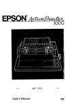
4.2.3 LED and indicator light description
There is 4-bit 8-section LED, 3 unit lights, 3 status indicator lights on the local
operation keypad of the inverter, shown as diagram4-3:
Hz
A
Hz
S
V
A
S
V
No unit
A
Hz
Hz
Hz
A S
A
V
V
V
Hz
A
S
S
V
V
Hz
S
Go out
Go on
Diagram 4-3 Relation between unit indicator light and unit
- 34 -
S
A
℃
VF5000 series high capacity vector control inverter service manual
Three status indicator lights: FWD (forward run), REW (reverse run), ALM
(alarm) from left to right on the upper part of LED, their respective indicating
meaning is shown in table 4-1
Table 4-1 Status indicator light description
Item
Function description
LED display Display current run status parameter and set parameter
Status indicator light
Display function
Forward run indicator light, indicates that the inverter The inverter works
FWD output forward phase order and the connected motor in DC brake status
rotates in forward direction
if FWD 、 REV
indicator lights go
Reverse run indicator light, indicates that the inverter
on at the same
REV output reverse phase order and the connected motor
time.
rotates in reverse direction
ALM When inverter occurs fault alarming, this light will go on.
4.2.4 Keypad display state
VF5000 keypad display status is classified as stop parameter display status,
function code parameter editing status display, malfunction alarm status display, and
run status parameter display in total 4 kinds of status.
1. Stop parameter display status
The inverter is in stop status and the status supervision parameter, usually the
setting frequency (D-00) is displayed on keyboard. Unit is displayed by rightward
unit indicator light.
To press ►► key,it can display different stop status supervision parameters
circularly (default d group of supervision parameter, for detail please see d group
status supervision parameter in function parameter schedule graph of chapter 5).
Pressing PRG , ▲ , ▼
to switch and display status will be switched to
constant supervision parameter F3.04 (namely set frequency), which is set by D-00,
displays automatically if there is no key pressed within 1 minute.
2. Run parameter display status
The inverter enters into run status when receiving effective run command and run
status supervision parameter normally output frequency (D-00) is displayed on the
keyboard. Unit is displayed by rightward unit indicator light.
To press ►►
key, it can display different run status supervision parameter
circularly. Pressing PRG and ▲ , ▼ to switch and display status will be
switched to constant supervision parameter F3.04 (namely set frequecncy), which is
- 35 -
VF5000 series high capacity vector control inverter service manual
set by D-00, display automatically if there is no key pressed within 1 minute.
3. Failure alarm display status
The inverter enters into failure alarm display status upon detecting failure signal
and displays failure code sparklingly (as shown in Fig. 4-4). To press PRG enters
into program mode to check d group parameter. It can be carried on failure
STOP
restoration by pressing key RESET on the keypad, control terminal or ommunication
command after troubleshooting. Keep displaying failure code if failure exists
continuously.
Diagram 4-4 Failure alarm display status
Warning:
4. Function code editing status
Under waiting, run or failure alarm status, press
PRG key, can enter into
editing ststus and editing status is displayed according to two chasses’ menu mode,
as shown in diagram 4-5. The sequence is function code→function code parameter;
pressing SET
key can enter into one class by one class by one class. Under
function parameter display status, to press SET key to carry on parameter storage
operation, to press PRG
key can only come back to upper class menu without
storing modified parameter.
PRG
SET
PRG
PRG
PRG
Stop status parameter
display or run status
parameter display or
fault alarm display Diagram
SET
PRG
Editing status
4-5 Programming display status of operating panel
- 36 -
VF5000 series high capacity vector control inverter service manual
4.2.5 Method for using keypad
Can carry on various operations to the inverter through operating keypad, for
example:
1. Ststus parameter display switching:
Pressing key ►► display D group status supervision parameter. Method for
switching is shown as diagram 4-6:
LED
50.00
display
Output Freq.
►►
Press
key
►►
Parameter
Parameter
Parameter
Set Freq.
►►
Parameter
Terminal status
Output current
►►
Output voltage
Parameter
►►
``````
Motor speed
►►
Diagram 4-6 Example of Run status parameter display operating
(1) Only D-00 ~ D-28 status parameters can be displayed when shipping out the
inverter.
(2) Pressing SET key to switch into defaulting supervision display status directly
when the user see about status supervision parameter. Defaulting supercision
parameter in stop ststus is set frequency and in status, it is output frequency.
2. Setting of function code parameter
Take function code F2.19 modified from 10.00Hz to 18.50Hz as example.
LED
50.00
display
D-01
PRG
Press
key
f
F0.00
PRG
Enter into Enter into
editing status group F
Stop
parameter
parameter
display
status
50.00
PRG
Edit editing
status
F2.19
10.00
10.00
SET
►►
▲
Confirm function
group to enter into
calss 2 menu
F2.19
Confirm
function code
Amend parameter
and choose
parameter
18.50
18.00
SET
▲
►►
Store the amended
value and return to
class 2 menu to
display the next
function code
Amend
parameter
0→5
Amend parameter
and choose
parameter
Diagram 4-7 Example of editing parameter operation
- 37 -
18.00
▲
Amend
parameter
0→8
VF5000 series high capacity vector control inverter service manual
Description: under menu status, if the parameter has no flashing digit, this function
code can not be modified, possible reasons are as follows:
(1) This function code is the parameter that is not amendable, for example, actual
detected status parameter, run record parameter etc;
(2) This function code can not be modified under run status and can be changed after
stopping running.
(3) When parameter is protected, all the function codes can not be modified.
3. Jog run operation
Assumed keypad as current run command channel, jog run frequency 10Hz, in stop
status, the example as follows:
LED
display
Press
key
50.00
Press
Wait
JOG
Display set
frequency
10.00
0.01
Hold
50.00
0.01
Releas
…
JOG
Stop
Output frequency
Output Freq.
down to 0Hz and
up to 10Hz
stop
Diagram 4-8 Example of jog run operation
JOG
Display run by
output Frequency
4. Run, stop and forward/reverse switching
Assumed keypad as current run command channel, specified frequency
20.00HZ, forward run, in waiting status, the example as follows:
LED
20.00
Display
Press
key
FWD
00.01 Up
FWD
REV
20.00 Down 00.00 Up
RUN
FWD
►►
►►
Stop, Display running
Display output Freq. that
set Freq. is up to 20.00Hz
REV
20.00 Down 00.00 Up
Display running output
Freq. that is down to
0Hz in forward running
and is up to 20.
Display running output
Freq. Down to 0Hz in
reverse running, up to
20.00Hz in forward
running
20.00
20.00
STOP
RESET
Stop
In stop status,
display
set
frequency.
Diagram 4-9 Example of jog run operation
5. Specified frequency keypad▲
▲、▼key providing operation
Assumed current status is stop parameter stop ststusF0.01=1, the operation as
follow:
(1) Frequency adjustment is provided with integral way;
(2) Pressing ▲ key not release, the lowest digit increase at first; if the tens digit
carries on, tens digit increase; if the hundreds digit carries on, hundreds digit
increase… Pressing ▲
the ▲
key again after the key is released, value
increases from lowest digit again.
- 38 -
VF5000 series high capacity vector control inverter service manual
(3) Pressing ▼
key not release, the lowest digit decrease at first; if the tens
digit carries on, tens digit decrease; if the hundreds digit carries on, hundreds digit
decrease… Pressing the ▼
key again after the key is released, value deceases
from lowest digit again.
4.3 Inverter electrification
4.3.1 Check before electrification
Please carry on wiring based on operation requirement provided in “Inverter
wiring” of this manual.
4.3.2 Initial electrification
Close input side AC power supply switch after correct wiring and power supply
confirmed, electrify the inverter and keypad LED display starting status, contactor
closes normally, and LED displaying set frequency shows that electrification is
finished.
- 39 -
VF5000 series high capacity vector control inverter service manual
5
F0.00
Specification of function parameter table
5.1 Basic parameter
Control mode
Set range
Factory default
0
Sensorless vector control
1
V/F control
1
0: Sensorless vector control: It is widely used for the application which requires high
torque at low speed, higher speed accuracy, and quicker dynamic response, such as
machine tool, injection molding machine, centrifugal machine and wire-drawing
machine,etc.
1: V/F control: It is suitable for general purpose application such as pumps, fans etc.
F0.01
Frequency input channel selection
Set range
Factory default
0
Keypad otentiometer setting
1
Digital setting 1, keypad
2
Digital setting 2 (terminal UP/DOWN adjust)
3
Digital setting 3 (serial port)
4
Terminal VCI analog setting(0~10V)
5
Terminal CCI analog setting(0~20mA)
6
Terminal pulse(0~10kHz)
7
Combination setting
8
Outer terminal
0
0: Keypad otentiometer setting: Set running frequency by keypad otentiometer.
1: Digital setting 1, keyboard: Initial set frequency value is F0.03, can change set
frequency by changing F0.03 parameter through keypad, and you can also modify
F0.03 by ▲/▼ key.
2: Digital setting 2, terminal UP/DOWN adjust: Initial set frequency value is the
value stored during the last power off time, and you can adjust set running frequency
by terminal UP/DOWN.
3: Ditital setting 3: Change the set frequency by set frequency command of RS485
serial port.
4: VCI analog setting(0 ~ 10V): External analog voltage setting is used as set
frequency. Please refer to parameter F5.00-F5.01。
- 40 -
VF5000 series high capacity vector control inverter service manual
5: CCI analog setting(0 ~ 20mA): External analog current setting is used as set
frequency. Please refer to parameter F5.02-F5.03。
6: Terminal pulse (0~ 10kHz): Pulse frequency input from terminal X6 is used as
the set frequency, the corresponding relation between input frequency and set
frequency is determined byF5.04-F5.05
7: Combination setting: Each channel combination setting is used as set frequency.
Please refer to parameter F2.09.
8: Outer terminal
F0.02
Digital frequency control
Set range
Factory default
00
00-11
LED first bit:
0: When the drive is powered off or at undervoltage state, update F0.03 by the actual
frequency at that time.
1: when the drive is powered off or at undervoltage state, F0.02 remains unchanged.
LED second bit:
0: the reference frequency when the drive stops will be saved.
1: The reference frequency will restore to F0.02 when the drive stops.
F0.03
Frequency digital seeting
Set range
Factory default
0
0.00-upper limit frequency
When the setting way of running frequency is 1, namely, when the operatingpanel
sets (F0.01=1), this function parameter is the initial set frequency of inverter.
F0.04
Run command channel selection
Set range
Factory default
0
Keypad run control
1
Terminal run command control
2
Serial port run command control
0
This parameter is used to choose the running command; there are total three running
commands for selection
0: Keypad run control: Press RUN 、 STOP/RESET 、 REV/JOG on the operating
panel to control the start and stop
1: Terminal run command control: Use external control terminal FWD and REV to
- 41 -
VF5000 series high capacity vector control inverter service manual
control the start and stop.
2: Control the start and stop by the serian port.
F0.05
Run direction setting
Set range
Factory default
0
Forward run
1
Reverse run
2
Prevent reversing
0
0: Forward run: The actual running direction is indentical with the set direction.
1: Reverse run: When this way is chosen, the actual output phase sequency of
inverter is opposite to the set direction, if terminal control, FWD-COM will close,
the motor will rotate reversely. The function of RUN key on the keypad turns to
reverse running.
F0.06
Upper limit frequency
Set range
F0.07
50.00Hz
Factory default
0.00Hz
[F0.07]—400.0Hz
Lower limit frequency
Set range
Factory default
0.00Hz—[F0.00]
Upper limit frequency is set to the upper limit of output frequency, set range is
[F0.07]—400.0Hz;
Lower limit frequency is set to the lower limit of output frequency, set range is
0.00Hz—[F0.06];
F0.08
Basic run frequency
Set range
Factory default
50.00Hz
1.00-upper limit frequency
Basic frequency normally corresponds with the rated frequency of the motor. It is
the Min frequency when the drive outputs the highest voltage.
F0.09
Max output voltage
Set range
Factory default
380V/220V
200V—500V/100V—250V
Max output voltage is the drive’s output voltage when the drive outputs base
frequency. This corresponds to the rated voltage of the motor.
- 42 -
VF5000 series high capacity vector control inverter service manual
F0.10
G/P option
Set range
Factory default
0
G model
1
P model
0
0: Applicable to constant torque load
1: Applicable to variable torque load such as pumps and fans.
VF5000 series inverters provide the G/P integration function. The adaptive motor
powerused for constant torque load (G model) should be one grade less than that
used forvariable torque load (P model).
F0.11
Torque boost mode
Set range
F0.12
0
Manual boost
1
Automatic boost
Torque boost
Set range
Factory default
0
Factory default
Depend on model
0—30%
Manual boost: Torque boost voltage is determined completely by parameter F0.12,
its characteristic is boost voltage fixed, but the motor is prone to magnetic saturation
when lightly loaded.
Automatic boost: Torque boost voltage varies as stator current of the motor changes,
bigger stator current corresponds to bigger boost voltage.
In order to compensate the low frequency torque, boost the output voltage in the low
frequency zone as Vb shown in Fig. 5-1.
Fig 5-1 Torque boost
- 43 -
VF5000 series high capacity vector control inverter service manual
F0.13
Slip frequency compensation
Set range
Factory default
0.0%
0.0—150.0%
The change in motor torque will affect motor slip and result in speed change.
Through slip compensation, the output frequency can be adjusted according to motor
load torque, so as to reduce speed change caused by load change.
F0.14
Acc time 1
Factory default
Depend on model
F0.15
Dec time 1
Factory default
Depend on model
Set range
0.1—3600s
Acceleration time denotes the time from 0 Hz acceleration to upper-limit frequency.
Deceleration time denotes the time from upper-limit frequency deceleration to 0 Hz.
F0.16
V/F curve setting
Set range
Factory default
0
0-3
0: Constant torque curve: Applicable for most loads, is shown as the straight line.
1: Degressive torque curve 1: A 1.7-order curve is selected.
2: Degressive torque curve 2: A 2-order curve is selected.
The above V/F curves except the constant torque curve are suitable for the
variable-torque loads such as fan & pumps. The user can select the curves according
to the actual load so as to achieve the best energy-saving effects.
3: End-user sets V/F curve himself: You can define a curve byF0.17~F0.22
F0.17
V/F frequency value F1
Set range
F0.18
F0.20
25.0%
Factory default
25.00Hz
Frequency value F1—Frequency value F3
V/F voltage value V2
Set range
Factory default
0.0—Voltage value V2
V/F frequency value F2
Set range
12.50Hz
0.00—Frequency value F2
V/F voltage value V1
Set range
F0.19
Factory default
Factory default
Voltage value V1—Voltage value V3
- 44 -
50.0%
VF5000 series high capacity vector control inverter service manual
F0.21
V/F frequency value F3
Set range
F0.22
Factory default
75.0%
Voltage value V2—100.0%
REV/JOG
Set range
37.50Hz
Frequency value F2—Basic run frequency
V/F voltage value V2
Set range
F0.23
Factory default
Factory default
0
REV
1
JOG
1
5.2 Motor and vector control parameters
F1.00
Motor rated voltage
Set range
F1.01
F1.03
F1.04
Factory default
Depend on model
Factory default
50.00Hz
Factory default
0.1A
1.00—400.00Hz
Current without load
Set range
Depend on model
300—6000RPM
Motor rated Frequency
Set range
Factory default
0.1—500.0A
Motor rated speed
Set range
380V/220V
200V—500V/100V—250V
Motor rated current
Set range
F1.02
Factory default
0.1—500.0A
In order to achieve superior performance, please set these parameters according to
motor nameplate, then perform autotuning. The power rating of inverter should
match the motor. If the bias is too big, the control performances of inverter will be
deteriorated distinctly.
F1.05
Motor stator resistance
Set range
F1.06
Depend on model
Factory default
Depend on model
0.001—10.000Ω
Motor rotor resistance
Set range
Factory default
0.001—10.000Ω
- 45 -
VF5000 series high capacity vector control inverter service manual
F1.07
Motor leakage inductance
Set range
F1.08
F1.09
Depend on model
Factory default
Depend on model
0.01—600.00mH
Motor mutual inductance
Set range
Factory default
0.01—600.00mH
Reserved
After autotuning, the value of P1.05~P1.08 will be automatically updated.
Notice: Do not change these parameters, otherwise it may deteriorate the
control performance of inverter.
F1.10
Slip compensation rate
Set range
Factory default
1.00
0.50—2.00
The parameter is used to adjust the slip frequency of vector control and improve the
precision of speed control. Properly adjusting this parameter can effectively restrain
the static speed bias.
F1.11
Pre-excitation selection
Set range
F1.12
0
Valid under certain condition
1
Permanently invalid
Pre-excitation time
Set range
F1.13
Factory default
Factory default
0.2S
Factory default
0
0.1~10.0S
Motor parameters autotuning
Set range
0
0
No action
1
Static autotuning
0: No action
1: Static autotuning
If it is difficult to disconnect the load, static autotuning is recommended. The
operation process is the same as rotation autotuning except step c.
The Mutual inductance and current without load will not be detected by static
autotuning, if needed user should input suitable value according to experience.
- 46 -
VF5000 series high capacity vector control inverter service manual
F1.14
ASR proportional gain Kp
Set range
F1.15
1.00
Factory default
2.00S
0.01~5.00
ASR integral time Ki
Set range
Factory default
0.01~10.00S
F1.14, F1.15 are only valid for vector control and invalid for V/F control.
Through F1.14, F1.15, you can set the proportional gain P and integration time I of
speed regulator, so as to change the speed response characteristic. The system's
dynamic response can be faster if the proportion gain P is increased; However, if P
is too large, the system tends to oscillate. The system dynamic response can be faster
if the integration time I is decreased; However, if I is too small, the system becomes
over adjusted and tends to oscillate. Proportion gain P is usually adjusted first.
Under the condition that the system is immune from oscillation, P can be increased
as big as possible. Then adjust integration time I so that the system responds fast and
will not be over adjusted.
5.3 Auxiliary parameter
F2.00
Starting way
Set range
F2.01
0
Start from start frequency
1
Speed tracking start
Starting frequency
Set range
F2.02
Factory default
Factory default
0.00Hz
Factory default
0.0s
0.00—10.00Hz
Starting Frequency duration
Set range
0
0.0~10.0s
0: Start from start frequency
When inverter begins running, it starts from start frequency (F2.01) and runs for the
preset time at this frequency (F2.02) according to the setting values of F2.01 and
F2.02; then it enters normal Acc mode according to preset Acc time and Acc/Dec
mode parameters, at last it acelerates to preset frequency.
1: Speed tracking start
When the inverter begins running, first it detects the motor 's speed and direction,
then it starts smoothly at the detected speed and direction. Smooth start without
impaction should be performed on spinning motor.
- 47 -
VF5000 series high capacity vector control inverter service manual
When this start mode is selected, the system's inertia should be considered, and the
setting value of Acc/Dec time should be increased properly.
Start frequency: It is the initial frequency when the inverter starts from 0 Hz.
In the Acc and Start process, if the preset frequency is lower than the start frequency,
inverter's output frequency becomes zero.
Start frequency is effective in each Acc process in FWD and REV running process.
Start frequency holding time: the running time at start frequency in Acc/Start
process.
Start frequency holding time is effective in each Start process and FWD/REV
running switching process.
F2.03
DC brake current at starting
Set range
F2.04
0.0%
Factory default
0.0s
0—100.0%
DC brake time at starting
Set range
Factory default
0.0—30.0s
DC braking current at start: percentage of braking current when the inverter starts in
DC injection braking process.
DC braking time at start: holding time for output DC injection braking current when
the inverter is in start process.
If DC injection braking time at start is set to 0.0 second, DC injection braking
function is disabled.
F2.05
Acc./Dec. mode selection
Set range
Factory default
0
Linear Acc./Dcc. Mode
1
S curve Acc./Dec. mode
0
Acc/Dec modes 0 and 1 are valid in Start, Stop, FWD/REV, Acc and Dec process.
0: Linear Acc./Dcc. Mode: In Acc/Dec process, the relationship between output
frequency and Acc/Dec time is linear. The output frequency increases or decreases
at the constant slope.
1: S curve Acc./Dec. mode: In Acc/Dec process, the relationship between output
frequency and Acc/Dec time is nonlinear. The output frequency increases or
decreases according to the S curve.
- 48 -
VF5000 series high capacity vector control inverter service manual
F2.06
Time of S curve's start part
Set range
F2.07
20.0%
Factory default
60.0%
10.0—40.0%
Time of S curve's up/down part
Set range
Factory default
10.0—40.0%
The function codes of F2.06 and F2.07 define the Acc/Dec parameters of S curve.
S curve start time is the stage when the slope of output frequency rises gradually.
S curve rise time is the stage when the slope of output frequency maintains Phase.
S curve end time is the stage when the slope of output frequency decreases to zero.
The combination using of function codes F2.05~F2.07 is specially suitable for the
start and stop process of conveying load.
F2.08
AVR function
Set range
Factory default
0
No action
1
Action
1
0: No action
1: Action: AVR: auto voltage adjustment. This function can keep constant output
voltage when the input voltage deviates from rated value. Therefore, the function
should be enabled all the time especially when the input voltage is higher than the
rated value. If AVR is disabled during deceleration, the Dec time is shorter but the
current is higher, otherwise, the motor decelerates smoothly with lower current, but
the Dec time is longer.
F2.09
Automatic energy-saving run
Set range
0
No action
1
Action
Factory default
0
0: No action
1: Action
The drive can detect load current and adjust voltage accordingly to save energy.
F2.10
FWD/REV dead time
Set range
Factory default
0.1—10.0s
- 49 -
0.0s
VF5000 series high capacity vector control inverter service manual
It refers to the time period when the drive’s rotation changes from FWD to REV or
REV to FWD.
F2.11
Stop mode
Set range
Factory default
0
Decelerating and stopping
1
Coast to stop
0
0: Decelerating and stopping: When the inverter reveives the command of stop, it
will reduce the output frequency gradually according to the deceleration time, when
the frequency falls down to zero, the inverter will stop.
1: Coast to stop: After the inverter receives the stop command, it stops its output
immediately; the motor will stop according to its inertia. When selecting this mode,
fast stopping can be realized through external mechanical braking.
F2.12
Initial frequency of DC injection
braking
Set range
F2.13
F2.14
Factory default
0.0%
Factory default
0.0s
0.0—100.0%
DC injection braking time
Set range
0.00Hz
0.0—20.00Hz
DC injection braking current
Set range
Factory default
0.0—30.0s
Initial frequency of DC injection braking: It is the frequency when the inverter's
output frequency is decreased to zero along the Dec curve in Dec-to-stop process.
When the inverter is in Dec-to-stop process, if the preset frequency is lower than the
initial frequency of DC injection braking, then the output frequency become zero.
Initial frequency of DC injection braking is valid in the Dec process when the
inverter is switching between FWD and REV states.
If the user selects DC injection braking function, this frequency is also the initial
frequency of DC injection braking in stopping process.
If the running condition has no strict requirements for braking, the initial frequency
of DC injection braking should be set as low as possible.
DC injection braking current: Percentage of braking current when the inverter stops
in DC injection braking mode.
DC injection braking time: the time for maintaining output DC injection braking
- 50 -
VF5000 series high capacity vector control inverter service manual
current in inverter's stopping process.
F2.15
Restart after power failure
Set range
F2.16
0
No action
1
Action
2
Speed tracking start
Delay time for restarting after power
failure
Set range
Factory default
0
Factory default
0.5s
0.0—20.0s
When the power recovers from failures, the time before the inverter restarts is the
delay time.
This time is set according to the time needed by other equipment to recover when
the utility power recovers.
F2.17
Failure self-reset times
Set range
F2.18
0
Factory default
3.0s
0-10
Failure self-reset interval
Set range
Factory default
0.5-25.0s
The fault self-reset function is used to make the inverter that can’t run for load
fluctuation or other reasons resume to run with the set times (F2.17) and interval
(F2.18). In self-resertting course, the inverter resumes to run with the speed tracking
restart way. If in the range of the reset times by setting, the inverter can’t come back
to run normally, it will make the fault protection.
F2.19
Jog run frequency
Set range
Factory default
10.00Hz
0.00—50.00Hz
F2.20
Jog Acc.time
Factory default
Depend on model
F2.21
Jog Dec. time
Factory default
Depend on model
Set range
0.1—3600s
Jog running command can be issued through keypad, control terminal or host.
- 51 -
VF5000 series high capacity vector control inverter service manual
F2.22
Acc time 2
Factory default
Depend on model
F2.23
Dec time 2
Factory default
Depend on model
F2.24
Acc time 3
Factory default
Depend on model
F2.25
Dec time 3
Factory default
Depend on model
F2.26
Acc time 4
Factory default
Depend on model
F2.27
Dec time 4
Factory default
Depend on model
Set range
0.1-3600s
Three kinds of Acc/Dec time can be defined, and the drive’s Acc/Dec time 1~4 can
be selected by different combinations of control terminals, refer to F4.00~F4.05 for
the definitions of terminals used to select Acc/Dec time.
F2.28
Multi-frequency 1
Factory default
5.00Hz
F2.29
Multi-frequency 2
Factory default
10.00Hz
F2.30
Multi-frequency 3
Factory default
15.00Hz
F2.31
Multi-frequency 4
Factory default
20.00Hz
F2.32
Multi-frequency 5
Factory default
25.00Hz
F2.33
Multi-frequency 6
Factory default
30.00Hz
F2.34
Multi-frequency 7
Factory default
40.00Hz
F2.35
Reserved
Set range
0.00-upper limit frequency
This group of parameters defines the running frequency of section 1~7 of simple
multi-speed running, these running frequencies are used in the course of multi-speed
running. Please refer to parameter F7.00.
F2.36
Kick frequency 1
Factory default
0.00Hz
F2.38
Kick frequency 2
Factory default
0.00Hz
F2.40
Kick frequency 3
Factory default
0.00Hz
Set range
0.0—upper limit frequency
- 52 -
VF5000 series high capacity vector control inverter service manual
F2.37
Kick range 1
Factory default
0.00Hz
F2.39
Kick range 2
Factory default
0.00Hz
F2.41
Kick range 3
Factory default
0.00Hz
Set range
0.0—10.0Hz
Kick frequency is set to prevent the output frequency of inverter from meeting the
mechanical resonant point of load. In kick frequency parameters, set the system's
mechanical resonant centeral frequency, at most three frequency values can be setup.
Among the parameters of F2.37、F2.39、F2.41, the frequency range of the widest
resonant band can be set. After the jump frequency is set, even if the inverter's preset
frequency is in the resonant frequency band of the drive system, the inverter's output
frequency will be adjusted to be out of the resonant frequency band to avoid
resonance.
F2.42
Carrier frequency regulation
Set range
Factory default
Depend on model
1.0—12.0KHz
Carrier frequency will affect the noise of motor and the EMI of inverter.
If the carrier frequency is increased, it will cause better current wave, less harmonic
current and lower noise of motor.
The factory setting is optimal in most cases. Modification of this parameter is not
recommended.
If the carrier frequency exceeds the factory setting, the inverter must be derated
because the higher carrier frequency will cause more switching loss, higher
temperature rise of inverter and stronger electromagnetic interference.
If the carrier frequency is lower than the factory setting, it is possible to cause less
output torque of motor and more harmonic current.
F2.43
Carrier control mode
Set range
Factory default
0
Settled carrier
1
Automatic carrier adjusting
- 53 -
1
VF5000 series high capacity vector control inverter service manual
5.4 User’s management parameter
F3.00
LCD language
Set range
F3.01
0
Chinese
1
English
Parameter initialization
Set range
Factory default
0
Factory default
0
0
No action
1
Restore factory default
2
Clear fault records
0: No action
1: Inverter restores all parameters to factory default except F0.00、F0.01、F0.04、
F0.10
2: Inverter clear all fault records.
This function code will restore to 0 automatically when complete the function
operation.
F3.02
Parameter write protection
Set range
F3.03
F3.05
All parameters are allowed to be modified
1
Except frequency, others are not allowed to be
modified
2
Parameters are forbidden to overwrite expect this
parameter
0
Factory default
0
Factory default
1
0—18
LED 2 display(LCD)
Set range
Factory default
0—9999
LED 1 display (LED)
Set range
0
0
Manufacturer parameter
Set range
F3.04
Factory default
0—18
0: Output frequency (Hz)
1: Setting frequency (Hz)
- 54 -
VF5000 series high capacity vector control inverter service manual
2: Output current (A)
3: Output voltage (V)
4: Load motor speed (RPM/min)
5: Running linear speed (m/s)
6: Set linear speed (m/s)
7: Bus voltage (V)
8: Input AC power voltage (V)
9: Set PID value
10: Feedback PID value
11: Analog input VCI (V)
12: Analog input CCI (A)
13: Pulse input frequency (KHz)
14: Input terminal state
15: Heatsink temperature (℃)
16: Module temperature (℃)
17: Current count value
18: Setting count value
F3.06
Linear speed coefficient
Set range
Factory default
1.00
0.01—100.0
If displayed is line speed, line speed calculation factor:
Line speed = Frequency×Line speed factor.
F3.07
Closed-loop display coefficient
Set range
Factory default
1.00
0.01—100.0
The display value of closed-loop specified quantity/feedback quantity= closed-loop
specified quantity/feedback quantity×closed-loop parameter display factor.
F3.08
Sofeware version
Set range
F3.09
Factory default
0—99.99
Unit of Acc/Dec time
Set range
0
Second
1
Minute
Factory default
- 55 -
0
VF5000 series high capacity vector control inverter service manual
5.5 Digital input and output parameter
F4.00
Input terminal X1
Factory default
0
F4.01
Input terminal X2
Factory default
0
F4.02
Input terminal X3
Factory default
0
F4.03
Input terminal X4
Factory default
0
F4.04
Input terminal X5
Factory default
0
F4.05
Input terminal X6
Factory default
0
Set range
0—30
0: Leave control terminal unused
1: Multi-speed selection 1
2: Multi-speed selection 2
3: Multi-speed selection 3
ON/OFF combination of multi-speed running selection can define 7-section speed
running curve at most.
Multi-speed selection terminal are chosen by parameters F4.00~F4.05, the
multi-speed control of external terminal shall run by cooperating with the running
command. The section speed controlled by terminal is shown as following table.
Multi-speed
Multi-speed
Multi-speed
Multi-speed
terminal3
terminal2
terminal1
OFF
OFF
OFF
No Multi-speed
OFF
OFF
ON
1
OFF
ON
OFF
2
OFF
ON
ON
3
ON
OFF
OFF
4
ON
OFF
ON
5
ON
ON
OFF
6
ON
ON
ON
7
4: Acc/Dec time 1
5: Acc/Dec time 2
- 56 -
VF5000 series high capacity vector control inverter service manual
6~8: Frequency channel selection
Through ON/OFF combination of frequency provision channel selection terminal 6、
7、8, can realize frequency provision channel switch shown in Table 5-1.
9: Forward jog control
Be used for indendently forward jog control terminal which don’t need the
cooperation of FWD or REW terminal.
10: Reverse jog control
Be used for iindendently reverse jog control terminal which don’t need the
cooperation of FWD or REW terminal.
11: Free stop control
Be used for free stop control terminal in the external terminal control mode.
12: Frequency increasing command
Be used for increasing control of frequency.
13: Frequency decreasing command
Be used for decreasing control of frequency.
14: External device failure input
Can be input the external equipment fault signal to enable inverter to performa fault
monitoring against the external equipment.
15: Three-line run control
Refer to parameter F4.06
16: DC brake order
Used for carrying out DC brake for motor at the time of stopping, this terminal
realizes emergency stop and accurate location of motor. Please refer to the
parameters F2.12~F2.14.
17: Clear counter and input
Clearing the built-in counter, it is used together with NO.18 function (counter
triggering signal input)
18: Counter triggering signal input
Count pulse input port of built-in counter, and it can be used to store current count
value when power of inverter fails.
19: Pulse frequency input
This function terminal receives pulse signal as the frequency setting. The relation
between input signal pulse frequency and set frequency is shown as description of
F5.04、F5.05.
20: External reset input (RESET)
- 57 -
VF5000 series high capacity vector control inverter service manual
When the inverter makes fault alarming, this terminal can perform reset against fault.
Its function is identical with the STOP key on the keypad.
21: Frequency of UP/DOWN terminal clear
This terminal is used to clear the frequency set via external terminals (set the
frequency by frequency increase command UP/decrease command DOWN).
When the terminal is ON, frequency setting value is cleared. This function is
disabled for the frequency set by other setting modes.
22: PID running jump-in
23: Programmable multi-speed running
24: Run traverse operation jump-in
When traverse operation start mode is manual jump-in, traverse operation function
effective if this terminal effective.
25: Reset traverse operation
Reference frequency of inverter will be forced as center frequency of traverse
operation.
26: External stop order
This command is effective to all run command channel, when this function is
effective the inverter stops running in mode set by F2.11.
27: Drive operation prohibiting
If this function is enabled, the drive that is operating will coast to stop and the drive
ready to run will be prohibited to start. This function is mainly used as safety
protection.
28: Acc/Dec prohibit
The motor is immune to any external command except Stop command and maintain
the present speed.
Note:
This function is disabled during normal decelerating to stop.
29: Terminal control mode is enabled
When this terminal function is enabled, the operating command is input through this
terminal forcibly. The drive will be controlled in the previous mode if FWD/REV
terminal function is disabled.
30: Frequency reference is input via terminal CCI
If the setting is 30, the frequency reference will be input via terminal CCI forcibly.
The frequency input will be changed to the previous one if this terminal function is
disabled.
- 58 -
VF5000 series high capacity vector control inverter service manual
F4.06
FWD/REV terminal control mode
Set range
Factory default
0
Two-line control mode 1
1
Two-line control mode 2
2
Three-line control mode 1
3
Three-line control mode 2(Reserved)
0
2: Three-line control mode 1
In Fig. 5-2, SB1 is a normally closed button for stopping the motor, SB2 is a
normally open button for running the motor, SB3 is a normally open button for
Forward running the motor
Fig. 5-2 Three-line control mode 1
F4.07
pen collector output terminal Y1
setting
Factory default
0
F4.08
Open collector output terminal Y2
setting
Factory default
1
F4.09
Programmable Relay output TA TB
TC terminal
Factory default
12
0: Drive running signal
This signal will be given if the drive is running.
1: Frequency arriving signal
2: Frequency level detect signal
3: Inverter zero speed indication
4: External failure stop-running
The terminal outputs the indicating signal if the drive outputs tripping signal caused
by external fault
- 59 -
VF5000 series high capacity vector control inverter service manual
5: Output frequency reach upper limit
The signal is given if the preset frequency is higher than upper limit of frequency
and the operating frequency reaches the upper limit of frequency.
6: Output frequency reach lower limit
The signal is given if the preset frequency is higher than lower limit of frequency
and the operating frequency reaches the lower limit of frequency.
7: Completion of simple PLC operation stages
The signal (pulse, 500ms) is given if one cycle of PLC operation is finished.
8: Overload alarming signal
9: Ready
10: Counter detect signal output
11: Counter reset signal output
12: Inverter failure
13: Low voltage lock-up signal
14: Upper and lower limits of traverse frequency
The signal will be given if the range of traverse frequency calculated based on
central frequency is higher than upper limit of frequency or lower than the lower
limit of frequency
15: PLC cycle completion indication
The signal is given (pulse, 500ms) if the present stage of PLC operation is finished.
F4.10
FDT level setting
Set range
F4.11
Factory default
0.00Hz—upper limit frequency
FDT lag
Set range
0.00Hz
Factory default
1.00Hz
0.00Hz—30.00Hz
When the drive’s output frequency reaches FDT level, it outputs an indicating signal
until its output frequency drops below FDT level (FDT level-FDT lag).
F4.12
Frequency checkout scope (FAR)
Set range
Factory default
0.00Hz
0.00—15.00Hz
If the drive’s output frequency is within the detecting range of preset frequency, a
pulse signal will be output.
- 60 -
VF5000 series high capacity vector control inverter service manual
F4.13
Overload detection threshold
Set range
F4.14
100%
Factory default
1.0S
20—120%
Overload detection config
Set range
Factory default
0.0~15.0s
F4.13 defines the threshold for overload alarm. It is a percentage of either drive’s or
motor’s rated current.
F4.15
Preset counting value
Set range
F4.16
1
Factory default
1
0—9999
Specified counting value
Set range
Factory default
0—F4.15
When the number of pulses defined by F4.15 are input from X6, Y1 or relay will
output an indicating signal.
When the number of pulses defined by F4.16 are input from X6, Y1 or relay will
output an indicating signal which will last until the number of pulses defined by
F4.15 are input.
Fig. 5-3 Preset counting value and specified counting value
5.6 Analog input output parameter
F5.00
VCI input lower-limit voltage
Set range
F5.01
F5.02
0.0V
Factory default
10.0V
Factory default
0.0mA
0.0—F5.01
VCI input upper-limit voltage
Set range
Factory default
F5.00—10.0V
CCI input lower-limit current
- 61 -
VF5000 series high capacity vector control inverter service manual
Set range
F5.03
0.0—F5.03
CCI input upper-limit current
Set range
External pulse input lower limit
frequency
F5.05
External pulse input upper limit
frequency
Set range
F5.06
F5.07
0.0kHz
Factory default
10.0kHz
Factory default
0.00Hz
F5.04—20.0KHz
0.0Hz—upper limit frequency
Set frequency corresponding to
max analog input
Set range
Factory default
0.0—F5.05
Set frequency corresponding to
min. analog input
Set range
20.0mA
F5.02—20.0mA
F5.04
Set range
Factory default
Factory default
50.00Hz
0.0Hz—upper limit frequency
Parameters F5.06 and F5.07 are used for setting the corresponding relation between
external analog input capacity and set frequency.
F5.08
Delay time of analog input signal
Set range
Factory default
0.5s
0.1—5.0s
The system filters analog signal input from external voltage input and external current
with the setting filter time constant, to remove the influence from interference signal.
The longer the time goes by, the stronger the interference resistance gets, in addition,
the control is qutite stable, but the response is slower; on the contrary, the shorter the
time goes by, the more fast the response gets, but interference ability is poorer, and the
control may be unstable. In the practice use, if the best value can not be determined,
this parameter will be adjusted properly according to control and response situation.
F5.09
AOV analog output selection
Factory default
0
F5.10
DO1 pulse output selection
Factory default
2
Set range
0
Ouput frequency
- 62 -
VF5000 series high capacity vector control inverter service manual
F5.11
Setting frequency
2
Output current
3
Load motor speed
4
Output voltage
5
Bus-bar voltage
6
PID provision
7
PID feedback
AOV gain
Set range
F5.13
1
F5.12
Reserved
F5.14
Reserved
100%
Factory default
100%
20—200%
DO1 gain
Set range
Factory default
20—200%
You can change the measurement range or calibrate error of AOV and DO1 outputs
by adjusting the output gain.
F5.15
Frequency input channel
combination
Set range
Factory default
000—666
LED first bit: Operation 1
0: Keypad otentiometer setting
1: Digital setting 1
2: Reserved
3: Serial port setting
4: VCI
5: CCI
6: Terminal pulse
LED second bit: Operation 2
0: Keypad otentiometer setting
1: Digital setting 1
- 63 -
000
VF5000 series high capacity vector control inverter service manual
2: Reserved
3: Serial port setting
4: VCI
5: CCI
6: Terminal pulse
LED third bit: Operation 3
0: Keypad otentiometer setting
1: Digital setting 1
2: Reserved
3: Serial port setting
4: VCI
5: CCI
6: Terminal pulse
LED forth bit: Reserved
F5.16
Combination given of arithmetic
setting
Set range
00—54
LED first bit: Arithmetic 1
0: Add
1: Subtract
2: Absolute value (subtration)
3: Take maximum
4: Take minimum
LED second bit: Arithmetic 2
0: Add
1: Subtract
2: Absolute value (subtration)
3: Take maximum
4: Take minimum
5: Operation 3 not take part in operation
LED third bit: Reserved
LED forth bit: Reserved
- 64 -
Factory default
00
VF5000 series high capacity vector control inverter service manual
5.7 PID control parameter
Analog feedback control system: Input pressure specified quantity by VCI port,
transmit 4~20mA feedback value of pressure sensor to CCI port of, to from an
analog closed-loop control system through built-in PID controller.
F6.00
PID action setting
Set range
Factory default
00
00-11
LED first bit: Function setting
0: Close
1: Open
LED second bit: PID jump-in selection
0: Auto jump-in
1: Manual jump-in
LED third bit: Reserved
LED forth bit: Reserved
F6.01
PID provision channel selection
Factory default
1
F6.02
PID feedback channel selection
Factory default
4
Set range
0
Keypad otentiometer setting
1
Digital setting
2
Reserved
3
Reserved
4
VCI
5
CCI
6
Terminal pulse
7
VCI+CCI
8
VCI-CCI
9
MIN{VCI,CCI}
10
MAX{VCI,CCI}
- 65 -
VF5000 series high capacity vector control inverter service manual
F6.03
Digital setting of specified quantity
Set range
Factory default
0.00V
0.00—10.00V
When analog feedback is selected (F6.01=1), this function allows parameter setting
from keypad or serial port.
F6.04
Feedback channel gain
Set range
F6.05
F6.06
F6.07
Positive
1
Negative
0
Factory default
1.00
Factory default
1.00s
Factory default
0.0s
0.1—200.0s
Differential time Td
Set range
Factory default
0.01—10.00
Integral time Ti
Set range
F6.08
0
Proportional gain P
Set range
1.00V
0.01—10.00
Feedback channel polarity
Set range
Factory default
0.0—10.0s
Optimize the responsiveness by adjusting these parameters while driving an actual
load.
Use the following procedure to activate PID control and then adjust it while
monitoring the response.
1. Enabled PID control.
2. Increase the proportional gain (P) as far as possible without creating oscillation.
3. Reduce the integral time (Ti) as far as possible without creating oscillation.
4. Increase the differential time (Td) as far as possible without creating oscillation.
F6.09
Sampling cycle T
Set range
Factory default
0.00s
0.00—10.00s
Sampling cycle T refers to the sampling cycle of feedback value. The PI regulator
calculates once in each sampling cycle. The bigger the sampling cycle, the slower
the response is.
- 66 -
VF5000 series high capacity vector control inverter service manual
F6.10
Bias limit
Set range
Factory default
0.0%
0.0—20.0%
Bias limit defines the maximum bias between the feedback and the preset. PID stops
operation when the bias is within this range. Setting this parameter correctly is
helpful to improve the system output accuracy and stability.
F6.11
Closed-loop preset frequency
Set range
F6.12
0.00Hz
Factory default
0.0s
0.0-upper limit frequency
Preset frequency hold time
Set range
Factory default
0.0—6000.0s
The above parameters are helpful for the close-loop control to enter stable state
quickly.
After close-loop running is started, the drive will accelerate to the preset frequency
F6.11 within the accelerate time, and hold the frequency for a period of time (F6.12),
and then run according to close-loop characteristic.
If you don’t need preset frequency, just set F6.11 and F6.11 at 0.
F6.13
Sleep threshold
Set range
F6.14
10.00V
Factory default
0.00V
0.0—10.00V
Revival threshold
Set range
Factory default
0.0—10.00V
Sleep threshold define feedback value limit from work status to sleep status. If set
feedback value is smaller than this limit and the situation sustains for a sleep delay
time, the inverter will enter into sleep status from work status.
Revival threshold define feedback value limit from sleep status to work status. If set
feedback value is bigger than this limit and the situation sustain for a revival delay
time, the inverter will enter into work status from sleep status.
5.8 Programmable running parameter
F7.00
Programmable running control
Set range
000-114
- 67 -
Factory default
000
VF5000 series high capacity vector control inverter service manual
LED first bit: Run mode selection
0: No action
1: Single cycle
2: Continuous cycle
3: Maintain value of the last stage after 1 cycle
4: Traverse run
LED second bit: Programmable multi-speed (PLC) run jump-in
0: Auto jump-in
1: Manual jump-in
LED third bit: Traverse run jump-in
0: Auto jump-in
1: Manual jump-in
LED forth bit: Reserved
1: Single cycle
The drive stops after a single cycle automatically. It will start given another Run
command.
2: Continuous cycle
The drive continues running cycle after cycle until stop command is received.
3: Maintain value of the last stage after 1 cycle
The drive holds the frequency and direction of the last stage after single cycle.
F7.01
Phase 1 run time
Factory default
10.0s
F7.02
Phase 2 run time
Factory default
10.0s
F7.03
Phase 3 run time
Factory default
10.0s
F7.04
Phase 4 run time
Factory default
10.0s
F7.05
Phase 5 run time
Factory default
10.0s
F7.06
Phase 6 run time
Factory default
10.0s
F7.07
Phase 7 run time
Factory default
10.0s
F7.08
Reserved
Set range
0.0—6000.0s
F7.09
Multi-phase run direction 1
Factory default
0000
F7.10
Multi-phase run direction 2
Factory default
000
- 68 -
VF5000 series high capacity vector control inverter service manual
Set range
0000—1111(0: Forward
1: Reverse)
F7.01~F7.10 are to set frequency, direction, Acc/Dec time of PLC stages.
When the PLC operating direction is determined by operating commands, the
motor’s operating direction can be changed by external command. For example,
running forward can be ordered by terminal FWD-COM. The direction is decided by
running command and if it cannot be determined, the drive will runs in the direction
of last operating stage.
F7.11
Traverse operation control mode
Set range
Factory default
000
0000—111
LED first bit: Reserved
LED second bit: Traverse control
0: Fixed Traverse amplitude
1: Changing wobble amplitude
LED third bit: Stopping mode of traverse operation
0: Start as earlier state
1: Restart
LED forth bit: Save parameters upon power-off
0: Save
1: Not save
F7.12
Traverse preset frequency
Set range
F7.13
Factory default
0.00Hz—upper limit frequency
Waiting time before traverse
Set range
10.00Hz
Factory default
0.0s
0.0—3600.0s
F7.12 defines the frequency before entering traverse state.
When the traverse start, F7.13 specifies the time period that the drive run at preset
traverse frequency.
F7.14
Traverse amplitude
Set range
Factory default
0.0—50.0%
Varied amplitude: AW=central frequency×F7.14
Fixed amplitude: AW=max. frequency F0.06×F7.14
- 69 -
10.0%
VF5000 series high capacity vector control inverter service manual
F7.15
Step frequency
Set range
Factory default
0.0%
0.0—50.0%
If it is set at 0, then there will be no step frequency.
Practical step frequency =F7.15×F7.14
F7.16
Traverse cycle
Set range
Factory default
10.0s
0.1—3600.0s
It defines the period of traverse operation including rising time and falling time.
Note:
Under traverse mode, auto Acc/Dec is not allowed, otherwise, the traverse cycle will
become abnormal.
F7.17
Rising time of triangle wave
Set range
Factory default
50.0%
0.0—100.0%
It defines the rising time of traverse operation that equals to F7.16×F7.17 (s) and
falling time, F7.16×(1-F7.17) (s)
F7.18
Traverse central frequency
Set range
Factory default
10.00Hz
0.00—upper limit frequency
The central frequency of traverse operation is default as present reference frequency.
The traverse setting becomes invalid for close-loop and jog.
5.9 Communication parameter
F8.00
Local address
Set range
Factory default
1
0—31
This parameter is used to identify the address when the serial port communicates.
When this parameter is set to 0, this inverter is used as master when serial port
communicates, to control the running of other connected inverters.
When this parameter is set to 1~31, this inverter is used as slave to receive the date
from upper machine or master.
- 70 -
VF5000 series high capacity vector control inverter service manual
F8.01
Communication setting
Set range
Factory default
013
Factory default
10.0s
0000—0025
LED first bit: Baud rate option
0: 1200BPS
1: 2400BPS
2: 4800BPS
3: 9600BPS
4: 19200BPS
5: 38400BPS
LED second bit: Data format
0: No checkout
1: Even checkout
2: Odd checkout
LED third bit: Communication failure motion
0: Stop
1: Stand
LED forth bit: Reserved
This parameter sets the communication mode.
F8.02
Communicate timeout detect
Set range
0.0-100.0s
When the communication signal is lost for a period longer than the setting of this
parameter, the drive deems that communication fault occurs.
When it is set at 0, the drive will not detect the communication status.
F8.03
Response delay
Set range
Factory default
5ms
0-1000ms
Response delay refers to the time from the drive receiving and executing the
command of the host to returning reply frame to the host.
F8.04
Setting scale
Set range
Factory default
0.01-10.00
- 71 -
1.00
VF5000 series high capacity vector control inverter service manual
5.10 Protection function parameter
F9.00
Motor overload protection factor
Set range
Factory default
105%
30%—110%
In order to apply effective overload protection to different kinds of motors, the Max
output current of the drive should be adjusted.
The efficient is calculated by the formula below:
Motor overload protection coefficient= motor rated current / inverter's rated output
current×100%
Generally, the Max load current is the motor’s rated current.
If the motor’s rated current does not match that of the drive, adjust F9.00 to perform
overload protection.
F9.01
Under voltage protection level
Set range
F9.02
F9.03
Factory default
350V / 700V
330—380V / 660—760V
Current limit level
Set range
200V / 400V
180—240V / 360V—480V
Overvolltage limit level
Set range
Factory default
Factory default
180%
120%—220%
Current limit function is used to limit the load current under the preset current in real
time to avoid trip due to over-current. This function is especially useful for the
applications of larger load inertia or sharp change of load.
F9.03 defines the level for current limit. Its setting is a percentage of drive’s rated
current Ie.
5.11 Advanced function parameter
FA.00
Zero-frequency run threshold
Set range
FA.01
0.00Hz
Factory default
0.00Hz
0.00—50.00Hz
Zero-frequency hysteresis
Set range
Factory default
0.00—50.00Hz
The above two parameters are to set zero frequency hysteresis control.
- 72 -
VF5000 series high capacity vector control inverter service manual
This function can realize dormancy to save energy. In addition, the frequent start and
stop at threshold frequency can be avoided.
FA.02
Dynamic braking initial voltage
Set range
FA.03
350 / 700V
Factory default
50%
300—360V / 600—720V
Dynamic braking motion rate
Set range
Factory default
10—100%
The max. continuous dynamic braking time is calculated with 100s as a cycle.
The resistance and power of the braking resistor should be considered.
FA.04
Cooling fan control selection
Set range
FA.05
0
Auto running mode
1
Run all the time
UP/DOWN terminal speed limit
setting
Set range
Factory default
0
Factory default
1.00Hz/S
0.01Hz~100.0Hz/S
To define the increase / decrease rate when using UP/DOWN terminal to change
reference frequency.
FA.06
Overshoot enabled
Set range
0
Disabled
1
Enabled
Factory default
0
When the electric network voltage is much lower (under 15% of rated voltage) or
the drive works with a heavy load for long time, it will boost its bus voltage usage
rate to increase output voltage.
0: Disabled
1: Enabled
- 73 -
VF5000 series high capacity vector control inverter service manual
6 Function parameter table
6.1 Function parameter schedule graph
Notice: X---parameter can’t be changed in process of running
O---parameter can be changed in process of running
Basic parameter F0
Funct
ion
code
Name
Set range
Unit
Factory
default
Mod
ify
F0.00
Control mode
0: Sensorless vector control (SVC)
1: V/F control
1
1
X
Frequency input
channel selection
0: Keypad otentiometer setting
1: Digital setting 1, keypad
2: Digital setting 2, terminal UP/
DOWN adjust setting
3: Digital setting, serial port
setting
4: VCI analog setting (VCI-GND)
5: CCI analog setting (CCI-GND)
6: Terminal pulse(0~10KHZ)
7: Combination setting
8: Outer terminal
1
0
O
F0.02
Digital frequency
control
LED first bit: Save upon power-off
0: Save
1: Not save
LED second bit: Hold after stop
0: Hold
1: Not hold
LED third bit: Save
LED fourth bit: Save
1
00
O
F0.03
Frequency digital
seeting
0.00~upper limit Freq.
0.01Hz
50.00Hz
O
F0.04
Run command
channel selection
0: Keypad run control
1: Terminal run command control
2: Serial port run command control
1
0
O
F0.05
Run direction
setting
0: Forward run 1: Reverse run
2: Prevent reversing
1
0
O
F0.01
F0.06
Upper limit Freq.
MAX{F0.07,0.10Hz}~400.00Hz
0.01Hz
50.00Hz
X
F0.07
Lower limit Freq.
0.00~【F0.06】
0.01Hz
00.00Hz
X
F0.08
Basic run Freq.
1.00~Upper limit Frequency
0.01Hz
50.00Hz
X
F0.09
Max output
1
380V
X
380V: 200~500V
- 74 -
VF5000 series high capacity vector control inverter service manual
voltage
220V: 100~250V
G/P option
F0.11
Torque boost
mode
0: Manual boost
1: Automatic boost
F0.12
Torque boost
0.0~30.0%
0.1
F0.13
Slip frequency
compensation
0.0~150.0%
0.1
0.0
O
0.1
Depend on
model
O
0.1
Depend on
model
O
1
0
X
F0.14
F0.15
0: G type
1: P type
220V
F0.10
Acc time 1
1
0
X
1
0
X
0.1~3600
Dec time 1
0: Constant torque curve
1: Degressive torque curve 1 (the
1.7th power)
2: Degressive torque curve 2 (the
2th power)
3: End-user sets V/F curve himself
(determined by F0.17~F0.22)
O
F0.16
V/F curve setting
F0.17
V/F Frequency
value F1
0.00~Freq. value F2
0.01Hz
12.50Hz
X
F0.18
V/F Valtage value
V1
0.0~Valt. value V2
0.1%
25.0%
X
F0.19
V/F Frequency
value F2
Freq. value F1~Freq. value F3
0.01Hz
25.00Hz
X
F0.20
V/F Valtage value
V2
Valt. value V1~Valt. value V3
0.1%
50.0%
X
F0.21
V/F Frequency
value F3
Freq. value F2~basic run Freq.
0.01Hz
37.50Hz
X
F0.22
V/F Valtage value
V3
0.1%
75.0%
X
F0.23
REV/JOG
1
1
O
Unit
Factory
default
Mod
ify
1V
380V
220V
O
0.1A
Depend on
model
O
1RPM
Depend on
X
Valtage value V2~100.0%
0:REV
1:JOG
Motor and vector control parameters F1
Funct
ion
code
Name
F1.00
Motor rated
voltage
380V:200~500V
220V:100~250V
F1.01
Motor rated
current
0.1~500.0A
F1.02
Motor rated speed
Set range
300~6000RPM
- 75 -
VF5000 series high capacity vector control inverter service manual
model
F1.03
Motor rated Freq.
F1.04
Current without
load
F1.05
Motor stator
resistance
F1.06
1.00~400.00Hz
0.01Hz
50.00Hz
X
0.1A
Depend on
model
O
0.001~10.000Ω
0.001Ω
Depend on
model
X
Motor rotor
resistance
0.001~10.000Ω
0.001Ω
Depend on
model
X
F1.07
Motor leakage
inductance
0.01~600.00mH
0.01mH
Depend on
model
X
F1.08
Motor mutual
inductance
0.01~600.00mH
0.01mH
Depend on
model
X
0.01
1.00
O
1
0
X
0.1
0.2S
X
1
0
X
0.1~500.0A
F1.09
Reserved
F1.10
Slip compensation
rate
F1.11
Pre-excitation
selection
0: Valid under certain condition
1: Permanently invalid
F1.12
Pre-excitation
time
0.1~10S
F1.13
Motor parameters
autotuning
0: No action
1: Static autotuning
F1.14
ASR proportional
gain Kp
0.01~5.00
0.01
1.00
O
F1.15
ASR integral time
Ki
0.01~10.00S
0.01S
2.00S
O
Unit
Factory
default
Mod
ify
1
0
X
0.01Hz
1.00Hz
O
0.1s
0.0s
X
0.1%
0.0%
O
0.1s
0.0s
X
1
0
O
0.50-2.00
Auxiliary parameter F2
Funct
ion
code
Name
F2.00
Starting way
0: Start from start frequency
1: Speed tracking start
F2.01
Starting Freq.
0.00~10.00Hz
F2.02
Starting Freq.
duration
0.0~10.0s
F2.03
DC brake current
at starting
0.0~100.0%
F2.04
DC brake time at
starting
0.0: No action
F2.05
Acc./Dec. mode
selection
0: Linear Acc./Dcc. Mode
1: S curve Acc./Dec. mode
Set range
0.1~30.0s
- 76 -
VF5000 series high capacity vector control inverter service manual
F2.06
Time of S curve's
start part
10.0~40.0%
0.1%
20.0%
X
F2.07
Time of S curve's
up/down part
10.0~80.0%
0.1%
60.0%
X
F2.08
AVR function
0: No action
1: Action
1
1
X
F2.09
Automatic
energy-saving run
0: No action
1: Action
1
0
X
F2.10
FWD/REV dead
time
0.1~10.0s
0.1s
0.0s
X
F2.11
Stop mode
1
0
X
F2.12
Initial freq. of DC
injection braking
0.01Hz
0.00Hz
O
F2.13
DC injection
braking current
0.1%
0.0%
O
F2.14
DC injection
braking time
0.0: DC braking no action
0.1~30.0s
0.1s
0.0s
X
F2.15
Restart after
power failure
0: No action
1: Action
2: Speed tracking start
1
0
X
F2.16
Delay time for
restarting after
power failure
0.0~20.0s
0.1s
0.5s
X
F2.17
Failure self-reset
times
0~10
1
0
X
F2.18
Failure self-reset
interval
0.5~25.0s
0.1
3.0s
X
F2.19
Jog run frequency
0.01Hz
10.00Hz
O
0.1s
Depend on
model
O
F2.20
0: Decelerating and stopping
1: Coast to stop
0.00~20.00Hz
0.0~100.0%
0.00~50.00Hz
Jog Acc.time
0.1~3600
F2.21
Jog Dec. time
0.1s
Depend on
model
O
F2.22
Acc. time 2
0.1s
Depend on
model
O
0.1~3600
F2.23
Dec. time 2
0.1s
Depend on
model
O
F2.24
Acc. time 3
0.1s
Depend on
model
O
0.1s
Depend on
model
O
0.1s
Depend on
O
0.1~3600
F2.25
Dec. time 3
F2.26
Acc. time 4
0.1~3600
- 77 -
VF5000 series high capacity vector control inverter service manual
model
0.1s
Depend on
model
O
F2.27
Dec. time 4
F2.28
Multi-frequency 1
0.00~Upper limit frequency
0.01Hz
5.00Hz
O
F2.29
Multi-frequency 2
0.00~Upper limit frequency
0.01Hz
10.00Hz
O
F2.30
Multi-frequency 3
0.00~Upper limit frequency
0.01Hz
15.00Hz
O
F2.31
Multi-frequency 4
0.00~Upper limit frequency
0.01Hz
20.00Hz
O
F2.32
Multi-frequency 5
0.00~Upper limit frequency
0.01Hz
25.00Hz
O
F2.33
Multi-frequency 6
0.00~Upper limit frequency
0.01Hz
30.00Hz
O
F2.34
Multi-frequency 7
0.00~Upper limit frequency
0.01Hz
40.00Hz
O
F2.35
Reserved
F2.36
Kick Freq. 1
0.00~Upper limit frequency
0.01Hz
0.00Hz
O
F2.37
Kick range 1
0.0~10.0Hz
0.01Hz
0.00Hz
O
F2.38
Kick Freq. 2
0.0~Upper limit frequency
0.01Hz
0.00Hz
O
F2.39
Kick range 2
0.0~10.0Hz
0.01Hz
0.00Hz
O
F2.40
Kick Freq. 3
0.0~Upper limit frequency
0.01Hz
0.00Hz
O
F2.41
Kick range 3
0.0~10.0Hz
0.01Hz
0.00Hz
O
F2.42
Carrier Freq.
regulation
0.1Hz
Depend on
model
O
F2.43
Carrier control
mode
1
1
O
Unit
Factory
default
Mod
ify
1.0~12.0KHz
0: Settled carrier
1: Automatic carrier adjusting
User’s management parameter F3
Funct
ion
code
Name
F3.00
LCD language
F3.01
Parameter
initialization
Set range
0: Chinese
1: English
1
0
Oo
0: No action
1: Restore factory default
2: Clear fault records
1
0
X
0: All parameters are allowed to be
modified
1: Except frequency, others are not
allowed to be modified
2: Parameters are forbidden to
overwrite expect this parameter
1
0
O
F3.02
Parameter write
protection
F3.03
Manufacturer
parameter
0~9999
1
0
O
F3.04
LED 1 display
0~18(as follows)
1
0
O
F3.05
LCD 2 display
0: Output frequency (Hz)
1
1
O
- 78 -
VF5000 series high capacity vector control inverter service manual
1: Setting frequency (Hz)
2: Output current (A)
3: Output voltage (V)
4: Load motor speed (RPM/min)
5: Running linear speed (m/s)
6: Set linear speed (m/s)
7: Bus voltage (V)
8: Input AC power voltage (V)
9: Set PID value
10: Feedback PID value
11: Analog input VCI (V)
12: Analog input CCI (A)
13: Pulse input frequency (KHz)
14: Input terminal state
15: Heatsink temperature (℃)
16: Module temperature (℃)
17: Current count value
18: Setting count value
F3.06
Linear speed
coefficient
0.01~100.0
0.01
1.00
O
F3.07
Closed-loop
display coefficient
0.01~100.0
0.01
1.00
O
F3.08
Sofeware version
0~99.99
0.01
F3.09
Unit of Acc/Dec
time
0: Second
1: Minute
1
X
0
O
Unit
Factory
default
Mod
ify
1
0
X
1
0
X
1
0
X
1
0
X
1
0
X
1
0
X
Digital input and output parameterF4
Funct
ion
code
Name
F4.00
Input terminal X1
F4.01
Input terminal X2
F4.02
Input terminal X3
F4.03
Input terminal X4
F4.04
Input terminal X5
F4.05
Input terminal X6
Set range
0: Leave control terminal unused
1: Multi-speed selection 1
2: Multi-speed selection 2
3: Multi-speed selection 3
4: Acc/Dec time 1
5: Acc/Dec time 2
6: Frequency channel selection 1
7: Frequency channel selection 2
8: Frequency channel selection 3
9: Forward jog control
10: Reverse jog control
11: Free stop control
12: Freq. increasing command
- 79 -
VF5000 series high capacity vector control inverter service manual
13: Freq. decreasing command
14: External device failure input
15: Three-line run control
16: DC brake order
17: Clear counter and input
18: Counter triggering signal
input
19: Pulse frequency input
20: External reset input (RESET)
21: Frequency of UP/DOWN
terminal clear
22: PID running jump-in
23: Programmable multi-speed
running
24: Run traverse operation
jump-in
25: Reset traverse operation
26: External stop order
27: Drive operation prohibiting
28: Acc/Dec prohibit
29: Terminal control mode is
enabled
30: Frequency reference is input
via terminal CCI
31: Reserved
F4.06
FWD/REV
terminal control
mode
F4.07
Open collector
output terminal Y1
setting
F4.08
Open collector
output terminal Y2
setting
F4.09
Programmable
Relay output TA
TB TC terminal
0: Two-line control mode 1
1: Two-line control mode 2
2: Three-line control mode 1
3: Three-line control mode 2
0: Drive running signal
1: Frequency arriving signal
2: Frequency level detect signal
3: Inverter zero speed indication
4: External failure stop-running
5: Output freq. reach upper limit
6: Output freq. reach lower limit
7: Completion of simple PLC
operation stages
8: Overload alarming signal
9: Ready
10: Counter detect signal output
11: Counter reset signal output
12: Inverter failure
- 80 -
1
0
X
1
0
O
1
1
O
1
12
O
VF5000 series high capacity vector control inverter service manual
13: Low voltage lock-up signal
14: Upper and lower limits of
traverse frequency
15: PLC cycle completion
indication
F4.10
FDT level setting
F4.11
FDT lag
F4.12
Freq. checkout
scope (FAR)
F4.13
F4.14
Overload detection
threshold
Overload alarm
delay
F4.15
Preset counting
value
F4.16
Specified counting
value
0.00Hz~Upper limit frequency
0.01Hz
10.00Hz
O
0.0~30.00Hz
0.1Hz
1.00Hz
O
0.00Hz~15.0Hz
0.01Hz
5.00Hz
O
20~120%
1%
100%
O
0.0~15.0s
0.1s
1.0s
X
【F4.16】~60000
1
1
X
0~【F4.15】
1
1
X
Unit
Factory
default
Mod
ify
Analog input output parameter F5
Funct
ion
code
Name
F5.00
VCI input
lower-limit voltage
0.0~【F5.01】
0.1V
0.0V
O
F5.01
VCI input
upper-limit voltage
【F5.00】~10.0V
0.1V
10.0V
O
F5.02
CCI input
lower-limit current
0.0~【F5.03】
0.1mA
0.0mA
O
F5.03
CCI input
upper-limit current
【F5.02】~20.0mA
0.1mA
20.0mA
O
F5.04
External pulse
input lower limit
frequency
0.0~【F5.05】
0.1KHz
0.0KHz
O
F5.05
External pulse
input upper limit
frequency
【F5.04】~20.0kHz
0.1KHz
10.0KHz
O
F5.06
Set frequency
corresponding to
min. analog input
0.0Hz~Upper limit frequency
0.01Hz
0.00Hz
O
F5.07
Set frequency
corresponding to
0.0Hz~Upper limit frequency
0.01Hz
50.00Hz
O
Set range
- 81 -
VF5000 series high capacity vector control inverter service manual
max analog input
F5.08
Delay time of
analog input signal
F5.09
AOV analog
output selection
F5.10
DO1 pulse output
selection
F5.11
AOV gain
F5.12
Reserved
F5.13
DO1 gain
F5.14
Reserved
F5.15
Frequency input
channel
combination
F5.16
Combination given
of arithmetic
0.1~5.0s
0.1s
0.5s
O
1
0
O
1
2
O
20~200%
1%
100%
O
20~200%
1%
100%
0: Output frequency
1: Setting frequency
2: Output current
3: Load motor speed
4: Output voltage
5: Bus-bar voltage
6: PID provision
7: PID feedback
O
O
O
LED first bit: Operation 1
0: Keypad otentiometer setting
1: Digital setting 1
2: Reserved
3: Serial port setting
4: VCI
5: CCI
6: Terminal pulse
LED second bit: Operation 2
0: Keypad otentiometer setting
1: Digital setting 1
2: Reserved
3: Serial port setting
4: VCI
5: CCI
6: Terminal pulse
LED third bit: Operation 3
0: Keypad otentiometer setting
1: Digital setting 1
2: Reserved
3: Serial port setting
4: VCI
5: CCI
6: Terminal pulse
LED forth bit: Reserved
1
000
X
LED first bit: Arithmetic 1
0: Add
1
00
O
- 82 -
VF5000 series high capacity vector control inverter service manual
setting
1: Subtract
2: Absolute value (subtration)
3: Take maximum
4: Take minimum
LED second bit: Arithmetic 2
0: Add
1: Subtract
2: Absolute value (subtration)
3: Take maximum
4: Take minimum
5: Operation 3 not take part in
operation
LED third bit: Reserved
LED forth bit: Reserved
PID control parameter F6
Funct
ion
code
F6.00
Name
PID action setting
Set range
LED first bit: Function setting
0: Close
1: Open
LED second bit: PID jump-in
selection
0: Auto jump-in
1: Manual jump-in
LED third bit: Reserved
LED forth bit: Reserved
0: Keypad otentiometer setting
1: Digital setting
2: Reserved
3: Reserved
4: VCI
5: CCI
6: Terminal pulse
7: VCI+CCI
8: VCI-CCI
9: MIN{VCI,CCI}
10:MAX{VCI,CCI}
F6.01
PID provision
channel selection
F6.02
PID feedback
channel selection
F6.03
Digital setting of
specified quantity
0.00~10.00V
F6.04
Feedback channel
gain
0.01~10.00
- 83 -
Unit
Factory
default
Mod
ify
1
00
X
1
1
X
1
4
X
0.01V
0.00V
O
0.01
1.00
O
VF5000 series high capacity vector control inverter service manual
F6.05
Feedback channel
polarity
0: Positive
F6.06
Proportional gain
F6.07
Integral time
F6.08
Differential time
0.0: No differential
F6.09
Sampling cycle
0.00: Auto
F6.10
Bias limit
F6.11
Closed-loop
preset frequency
0.0~Upper limit frequency
F6.12
Preset frequency
hold time
F6.13
F6.14
1: Negative
1
0
X
0.01~10.00
0.01
1.00
O
0.1~200.0s
0.1s
1.0s
O
0.1s
0.0s
O
0.01s
0.00s
O
0.1%
0.0%
O
0.01Hz
0.00Hz
O
0.0~6000.0s
0.1s
0.0s
X
Sleep threshold
0.0~10.00V
0.01
10.00V
O
Revival threshold
0.0~10.00V
0.01
0.00V
O
0.1~10.0s
0.01~10.00s
0.0~20.0%
Programmable running parameter F7
Funct
ion
code
Name
Set range
Unit
Factory
default
Mod
ify
F7.00
Programmable
running control
LED first bit: Run mode selection
0: No action
1: Single cycle
2: Continuous cycle
3: Maintain value of the last stage
after 1 cycle
4: Traverse run
LED second bit: Programmable
multi-speed (PLC) run jump-in
0: Auto jump-in
1: Manual jump-in
LED third bit: Traverse run
jump-in
0: Auto jump-in
1: Manual jump-in
LED forth bit: Reserved
1
000
X
F7.01
Phase 1 run time
0.0~6000.0s
0.1s
10.0s
O
F7.02
Phase 2 run time
0.0~6000.0s
0.1s
10.0s
O
F7.03
Phase 3 run time
0.0~6000.0s
0.1s
10.0s
O
F7.04
Phase 4 run time
0.0~6000.0s
0.1s
10.0s
O
F7.05
Phase 5 run time
0.0~6000.0s
0.1s
10.0s
O
F7.06
Phase 6 run time
0.0~6000.0s
0.1s
10.0s
O
F7.07
Phase 7 run time
0.0~6000.0s
0.1s
10.0s
O
- 84 -
VF5000 series high capacity vector control inverter service manual
F7.08
Reserved
Multi-phase run
direction 1
LED first bit: Phase 1 direction
0: Forward
1: Reverse
LED second bit: Phase 2 direction
0: Forward
1: Reverse
LED third bit: Phase 3 direction
0: Forward
1: Reverse
LED forth bit: Phase 4 direction
0: Forward
1: Reverse
1
0000
O
Multi-phase run
direction 2
LED first bit: Phase 5 direction
0: Forward
1: Reverse
LED second bit: Phase 6 direction
0: Forward
1: Reverse
LED third bit: Phase 7 direction
0: Forward
1: Reverse
LED forth bit: Reserved
1
000
O
F7.11
Traverse
operation control
mode
LED first bit: Reserved
LED second bit: Traverse control
0: Fixed Traverse amplitude
1: Changing wobble amplitude
LED third bit: Stopping mode of
traverse operation
0: Start as earlier state
1: Restart
LED forth bit: Save parameters
upon power-off
0: Save
1: Not save
1
000
X
F7.12
Traverse preset
frequency
0.00Hz~Upper limit frequency
0.01Hz
10.00Hz
O
F7.13
Waiting time
before traverse
0.0~3600.0s
0.1s
0.0s
X
F7.14
Traverse
amplitude
0.0~50.0%
0.1%
10.0%
O
F7.15
Step frequency
0.0~50.0%
0.1%
10.0%
O
F7.16
Traverse cycle
0.1~3600.0s
0.1s
10.0s
O
F7.17
Rising time of
triangle wave
0.0~100.0%
0.1%
50.0%
O
F7.18
Traverse central
frequency
0.01Hz
10.00Hz
O
F7.09
F7.10
0.00Hz~Upper limit frequency
Communication parameter F8
- 85 -
VF5000 series high capacity vector control inverter service manual
Funct
ion
code
Name
F8.00
Local address
0: Host
Set range
Unit
Factory
default
Mod
ify
1~31: Slave
1
1
X
1
013
X
0.1s
10.0s
X
LED first bit: Baud rate option
0: 1200BPS
1: 2400BPS
2: 4800BPS
3: 9600BPS
4: 19200BPS
5: 38400BPS
LED second bit: Data format
0: No checkout
1: Even checkout
2: Odd checkout
LED third bit: Communication
failure motion
0: Stop
1: Stand
LED forth bit: Reserved
F8.01
Communication
setting
F8.02
Communicate
timeout detect
0.0~100.0s
F8.03
Response delay
0~1000ms
1ms
5ms
X
F8.04
Setting scale
0.01~10.00
0.01
1.00
O
Unit
Factory
default
Mod
ify
Protection function parameter F9
Funct
ion
code
Name
F9.00
Motor overload
protection factor
30%~110%
1%
105%
O
F9.01
Under voltage
protection level
180~240V /360~480V
1V
200/400V
O
330~380V /660~760V
1V
350/700V
O
120%~220%
1%
180%
O
Factory
default
mod
ify
F9.02
F9.03
Set range
Overvolltage limit
level
Current limit level
Advanced function parameter FA
Functi
on
code
Name
Set range
- 86 -
Unit
VF5000 series high capacity vector control inverter service manual
FA.00
Zero-frequency
run threshold
0.00~50.00Hz
0.01Hz
0.00Hz
O
FA.01
Zero-frequency
hysteresis
0.00~50.00Hz
0.01Hz
0.00Hz
O
FA.02
Dynamic braking
initial voltage
300~360V /600~720V
1V
350/700V
O
FA.03
Dynamic braking
motion rate
10~100%
1%
50%
O
FA.04
Cooling fan
control selection
0: Auto running mode
1: Run all the time
1
0
O
FA.05
UP/DOWN
terminal speed
limit setting
0.01Hz/S
1.00Hz/S
O
FA.06
Overshoot
enabled
1
0
X
FA.07
Reserved
FA.08
Reserved
FA.09
Reserved
FA.10
Reserved
FA.11
Reserved
FA.12
Reserved
0.01Hz~100.0Hz/S
0: Disabled
1: Enabled
- 87 -
VF5000 series high capacity vector control inverter service manual
7
Troubleshooting
7.1 Failure and countermeasure
When the inverter occurs abnormity, LED digitron will display the function
code and information about corresponding fault, fault relay will operate and inverter
will stop outputting, when the fault occurs, in case that the motor still raotates, it will
perform free stop, till it stops rotating. The permissible fault of VF5000 series is
shown as table 7-1,the fault code display range is E-01∽E-20. When finding the fault
of inverter, user shall examine according to this table first and record the symptom in
detail, and contact our after-sale service center or our sales agencies if need technical
service.
7-1Table of fault code and solution
Fault
Failure type
Possible reason
Countermeasure
code
E-01
Over current at
accelerating
operation
①too short accelerating time
②Ultra large load inertia
③Unsuitable V/F curve
④Too small inverter power
⑤ Restart the rotating motor
①Extend accelerating time
②Reduce the load inertia
③Reduce torque boost value or
adjust V/F curve
④Choose the inverter of large
power
⑤Set the speed-detection
start function
E-02
Over current at
decelerating
operation
①Too short decelerating time
②Ultra large load inertia
③Too small inverter power
①Extend decelerating time
②Reduce the load inertia
③Choose the inverter of large
power
E-03
Over current at
constant speed
operation
①Abnormal input voltage
②Load occurs abrupt change
or abnormity
③Too small inverter power
①Examine input power
②Examine load or reduce the
abrupt change of large power
③ Choose the inverter of
large power
E-04
Over voltage at
accelerating
operation
①Abnormal input voltage
②Restart the rotating motor
①Examine input power
②Set the speed-detection
start function
E-05
Over voltage at
decelerating
operation
①Too short decelerating time
②There is energy-feedback
load
③Abnormal input power
supply
①Extend decelerating time
②Add braking power of
external energy-consumption
braking unit
③Examine input power
E-06
Over voltage at
constant speed
①Abnormal input voltage
②Ultra large load inertia
①Examine input power
②Choose energy-consumption
- 88 -
VF5000 series high capacity vector control inverter service manual
operation
braking unit
E-07
Over voltage at
stopping
①Abnormal input supply
voltage
①Examine input supply
voltage
E-08
Under voltage
at operationg
①Abnormal input voltage
①Examine supply coltage
E-09
Phase failure of
input power
①Input power occurs phase
failure or abnormity
①Examine input power
①Inverter outputs short circuit
or earthes
②Instant over current of
inverter
③Too high environment
temperature
④Air flue is blocked or fan is
damaged
⑤DC auxiliary power supply
occurs fault
⑥Abnormal control panel
①Examine the connecting wire
②Refer to solution against
over current
③Reduce environment
temperature
④Clean the air flue or change
the fan
⑤Ask for service from
manufacturer or agency
①Too high environment
temperature
②Fan is damaged
③Flue is blocked
①Lower environment
temperature
②Change the fan
③Clean the flue and change
the ventilation condition
①Too high torque boost of
unsuitable V/F curve
②Too short accelerating time
③Too large load
①Reduce the torque boost and
adjust the V/F curve
②Extend accelerating time
③Reduce load or choose the
inverter of large power
①Too high torque boost or
unsuitable V/F curve
②Too low main voltage
③Locked rotor of motor or too
large abrupt change of load
④Incorrect setting of motor
overload protection factor
①Reduce the torque boost
value or adjust the V/F curve
②Examine main voltage
③Examine load
④Set the motor overload
protection factor correctly
Fault input terminal ofexternal
equipment closes
Open the fault input terminal
and remove the fault
①Improer setting of baud rate
②False of serial port
communication
③Without upper machine
①Set baud rate correctly
②Examine communication
cable and ask for service
③Check whether the upper
E-10
E-11
E-12
Module fault
Over heat
radiator
Overload of
inverter
E-13
Overload of
mortor
E-14
Fault of
external
equipment
E-15
Fault of serial
port
communication
- 89 -
VF5000 series high capacity vector control inverter service manual
communication signal
E-16
machine works and the
connection is correct
Reserve
①The current detecting device
is damaged or the circuit
occurs fault
②DC auxiliary power is
damaged
Ask for service from
manufacturer or agency
E-17
Incorrect
current
detcetion
①The circuit connecting
keyboard and control panel
occurs fault
②The terminal is poor in
connecting
① Ask for service
②Examine and reconnect
E-18
Fault of
communication
between
keyboard and
control panel
E-19
System fault
Quite serious inference and
false program reading
Ask for service from
manufacture or agency
E-20
Reserve
7.2 Enquiry of fault record
This series of inverters keeps the code of latest four times faults and the inverter
operating parameters of the last fault, to help user to enquire these information that
is good for finding the fault reason. All fault information is stored in groupD-22
~D-27 parameters; user can refer to the keyboard operating method to enter into
group D for inquiring the required information.
7.3 Fault reset
Please choose following any operation if requiring the fault inverter to recover
normal running.
STOP
1. When the inverter displays the fault code, you can press RESET key to reset.
2. When any one terminal of X1~X6 has been set to external RESET input (F4.00
~F4.04=20), it can break after closing with COM terminal.
3. Cut off power supply
- 90 -
VF5000 series high capacity vector control inverter service manual
Chapter 8 Maintenance
8.1 Maintenance
In case of change of service environment for inverter, such as temperature,
humidity, smog and aging of inverter internal parts, the inverter fault may occur.
Therefore, the inverter must be examined daily and given the regular maintenance in
period of storing and using.
8.1.1 Daily maintenance
When the inverter is turned on normally, please make sure the following items:
1. Whether the motor has abnormal noise and vibration.
2. Whether inverter and motor heat or occur abnormity.
3. Whether environment temperature is too high.
4. Whether the value of load ammeter is in conformity with the former.
5. Whether the fan of inverter rotates normally.
8.2 Regular maintenance
8.2.1 Regular maintenance
Before the inverter is maintained and checked, the power supply must be cut off,
in addition, the monitor shall have no display and main circuit power indicator lamp
goes out. The examined content is shown as table 8-1.
Table 8-1 Regular examined contents
Component
Check
Screw of main circuit
terminal and control
circuit terminal
Corrective action
Tighten.
- 91 -
VF5000 series high capacity vector control inverter service manual
Heatsink
Blow it away with dry
compressed air of 4~6
kg/cm² pressure
PCB printed circuit
board
Blow it away with dry
compressed air of 4~6
kg/cm ² pressure or dry
it with the hot air.
- 92 -
VF5000 series high capacity vector control inverter service manual
Cooling fan
Change the fan
- 93 -
VF5000 series high capacity vector control inverter service manual
Power unit
Blow it away with dry
compressed air of 4~6
kg/cm² pressure
Aluminum
electrolytic capacitor
Change the aluminum
electrolytic capacitor
- 94 -
VF5000 series high capacity vector control inverter service manual
- 95 -
VF5000 series high capacity vector control inverter service manual
8.2.2 Regular maintenance
In order to make the inverter run normally for a long time, the electronic
elements mounted in inverter shall be maintained regularly. And the service life of
electronic elements is different with the service environment and service condition.
The maintenance period of inverter as shown in the table 8-2 is provided for
referring.
Table 8-2 Changing time of inverter parts
Part name
Standard changing time
Fan
2~3yeras
Electrolytic capacitor
4~5 yeras
PCB
5~8 yeras
Fuse
10 yeras
Applicable condition for changing time of aforementioned inverter parts
1. Environment temperature: Annual average is 30℃.
2. Load factor: Less than 80%.
- 96 -
VF5000 series high capacity vector control inverter service manual
3. Running time: Less than 20 huors every day.
8.3 Warranty of inverter
If the inverter has the following situation, we can provide the warranty service.
1. The range of warranty only refers to the body of inverter.
2. When normally used, the inverter occurs fault or is damaged within 12
months, we will be responsible for warranty; if exceeding 12 months. We will charge
the reasonable maintenance fee.
3. Within 12 months, if the following situations occur, we also charge the
reasonable maintenance fee:
The inverter is damaged for that user doesn’t refer to the operating manual.
The inverter is damaged by reason of flood, fire, abnormity of voltage, etc.
The inverter is damaged by reason of false connection.
The inverter is damsged for that it is used for the abnormal purpose.
4. The relevant service fee is calculated according to actual cost. If a contract
has been set, we refer to the contract first for handling.
- 97 -